


INSTRUCTIONS for
F-9785-L
May, 2009
C-63 HEAVY DUTY
SERIES A
HAND CUTTING TORCH
DO NOT USE WITH ACETYLENE
These INSTRUCTIONS are for experienced operators. If you are not fully familiar with the principles of operation and safe
practices for oxy-fuel gas equipment, we urge you to read our booklet "Precautions and Safe Practices for Welding, Cutting, and
Heating", Form 2035. Do NOT permit untrained persons to operate this equipment. Do NOT attempt to operate this equipment
until you have read and fully understand these Instructions. If you do not understand these Instructions, contact your supplier for
further information.
The cutting torch covered by these Instructions is listed by third parties only when used in combination with cutting nozzles
and parts manufactured by ESAB Welding & Cutting Products to the specifications on file with third party listed, and when
they are used in the gas service for which they are designed and listed. The use of other welding tips, cutting nozzles and
parts that cause damage or failure to the equipment will void the manufacturer's warranty.
OPERATING INSTRUCTIONS
The C-63 is a high capacity three hose manual cutting
torch that can be used with any fuel gas EXCEPT acetylene.
CONNECTING
1. Attach oxygen and fuel gas regulators to station or
manifold supply valves.
2. Connect the oxygen and fuel gas hoses to the torch
and regulators. Cutting oxygen connection takes
the standard "C" size (1/2-in. hose) and the preheat oxygen and fuel gas connections take standard "B" size (3/8-in. hose).
3. Attach nozzle to torch head, and tighten connection nut with a wrench. (See chart on page 4.)
4. Check all connections including hose connections,
for gas leaks.
F-9785-L
ADJUSTING OXYGEN PRESSURES
1. Connect the OXWELD test gauge adaptor (Part
No. 21X48) between the 1/2-in. oxygen hose and
the torch cutting oxygen connection to determine
the actual cutting oxygen pressure at the torch.
Then open the torch cutting-oxygen valve wide and
turn in pressure-adjusting screw on the cuttingoxygen regulator until the test gauge shows the
desired cutting oxygen pressure as indicated in the
cutting chart. Note the pressure shown on the regulator gauge (it will vary with size nozzle being used,
length and conditions of hose, and condition of hose
fittings). Then release the pressure-adjusting
screw of the regulator, reopen the torch cuttingoxygen valve, and remove the test gauge adaptor
from the line. Readjust the regulator (with the cutting-oxygen valve on the torch open) until the regulator gauge shows the pressure noted after the first
adjustment.
2. Close the cutting-oxygen valve.
3. Open the preheat-oxygen valve about one full turn.
4. Turn in the pressure-adjusting screw on the preheat oxygen regulator until the delivery-pressure
gauge indicates the correct preheat-oxygen pressure. (The chart on page 4 shows the correct pressure to use.) Allow f or pressure drop through hose.
5. Close the preheat-oxygen valve.
ADJUSTING FUEL GAS PRESSURE
1. Open the fuel gas valve about one full turn.
2. Turn in the pressure-adjusting screw on the fuel
gas regulator until the delivery-pressure gauge indicates the correct pressure. (The chart on page
4 shows the correct pressure to use.) Allow for
pressure drop through hose.
3. Close the fuel gas valve.
Be sure this information reaches the operator.
You can get extra copies through your supplier.
READ AND UNDERSTAND INSTRUCTION MANUAL BEFORE INSTALLING
OR OPERATING. PROTECT YOURSELF AND OTHERS!
CAUTION
These INSTRUCTIONS are for experienced operators. If you are not fully familiar with the principles of operation and safe practices for gas welding and cutting equipment, we urge you to read
our booklet, “Precautions and Safe Practices for Gas Welding, Cutting, and Heating,” Form F-2035.
Do NOT permit untrained persons to install, operate, or maintain this equipment. Do NOT attempt
to install or operate this equipment until you have read and fully understand these instructions. If
you do not fully understand these instructions, contact your supplier for further information. Be
sure to read the Safety Precautions before installing or operating this equipment.
USER RESPONSIBILITY
This equipment will perform in conformity with the description thereof contained in this manual and accompanying labels and/or inserts when installed, operated, maintained and repaired in accordance with the instructions provided. This equipment must be checked periodically. Malfunctioning or poorly maintained equipment
should not be used. Parts that are broken, missing, worn, distorted or contaminated should be replaced immediately. Should such repair or replacement become necessary, the manufacturer recommends that a telephone
or written request for service advice be made to the Authorized Distributor from whom it was purchased.
This equipment or any of its parts should not be altered without the prior written approval of the manufacturer.
The user of this equipment shall have the sole responsibility for any malfunction which results from improper
use, faulty maintenance, damage, improper repair or alteration by anyone other than the manufacturer or a service facility designated by the manufacturer.
IMPORTANT SAFEGUARDS
When using Oxy-Fuel Gas Torches, basic safety precautions should always be followed:
Never use Acetylene gas at a pressure over 15 psig.a.
Never use damaged equipment.b.
Never use oil or grease on or around Oxygen equipment.c.
Never use Oxygen or fuel gas to blow dirt or dust o clothing or equipment.d.
Never light a torch with matches or a lighter. Always use a striker.e.
Always wear the proper welding goggles, gloves and clothing when operating Oxy-Acetylene equipment. f.
Pants should not have cus.
Do not carry lighters, matches or other ammable objects in pockets when welding or cutting.g.
Always be aware of others around you when using a torch.h.
Be careful not to let welding hoses come into contact with torch ame or sparks from cutting.i.
SAVE THESE INSTRUCTIONS.j.
BE SURE THIS INFORMATION REACHES THE OPERATOR.
YOU CAN GET EXTRA COPIES THROUGH YOUR SUPPLIER.
SAVE THESE INSTRUCTIONS!

SAFETY PRECAUTIONS
These Safety Precautions are for your protection. They summarize precautionary information from the references listed
in Additional Safety Information section. Before performing any
installation or operating procedures, be sure to read and follow the safety precautions listed below as well as all other
manuals, material safety data sheets, labels, etc. Failure to observe Safety Precautions can result in injury or death.
PROTECT YOURSELF AND OTHERS - Some
welding, cutting and gouging processes are
noisy and require ear protection. Hot metal can
cause skin burns and heat rays may injure
eyes. Training in the proper use of the processes and equipment is essential to prevent
1. Always wear safety glasses with side shields in any work area,
even if welding helmets, face shields, or goggles are also required.
2. Wear flameproof gauntlet type gloves, heavy long-sleeve shirt,
cuffless trousers, high-topped shoes, and a welding helmet or
cap for hair protection, to protect against hot sparks and hot
metal. A flameproof apron may also be desirable as protection
against radiated heat and sparks.
3. Hot sparks or metal can lodge in rolled up sleeves, trousers
cuffs, or pockets. Sleeves and collars should be kept buttoned,
and open pockets eliminated from the front of clothing.
4. Protect other personnel from hot sparks with a suitable nonflammable partition or curtains.
5. Use goggles over safety glasses when chipping slag or grinding. Chipped slag may be hot and can travel considerable distances. Bystanders should also wear goggles over safety
glasses.
1. Remove all combustible materials well away from the work
area or completely cover the materials with a protective nonflammable covering. Combustible materials include wood,
cloth, sawdust, liquid and gas fuels, solvents, paints and coatings, paper, etc.
2. Hot sparks or hot metal can fall through cracks or crevices in
floors or wall openings and cause a hidden smoldering fire on
the floor below. Make cert ain that such openings are protected
from hot sparks and metal.
3. Do not weld, cut, or perform any other hot work on materials,
containers, or piping until it has been completely cleaned so
that no substances on the material can produce flammable or
toxic vapors. Do not do hot work on closed containers. They
may explode.
4. Have fire extinguishing equipment handy for instant use, such
as a garden hose, a pail of water or sand, or portable fire
extinguisher. Be sure you are trained in its use.
5. After completing operations, inspect the work area to be sure
that there are no hot sparks or hot metal which could cause a
later fire. Use fire watchers when necessary.
6. For additional information, refer to NFPA Standard 51B, “Fire
Prevention in Use of Cutting and Welding Processes”, which
is available from the National Fire Protection Association,
Batterymarch Park, Quincy, MA 02269.
1. Always provide adequate ventilation in the work area by natural or mechanical ventilation means. Do not weld, cut, or gouge
on materials such as galvanized steel, stainless steel, copper ,
zinc, lead, beryllium, or cadmium unless positive mechanical
ventilation is provided. Do not breathe fumes and gases from
these materials.
2. If you develop momentary eye, nose, or throat irritation while
operating, this is an indication that ventilation is not adequate.
Stop work at once and take necessary step s to improve ventilation in the work area. Do not continue to operate if physical
discomfort persists.
accidents. Also:
FIRES AND EXPLOSIONS - Heat from a flame
can act as an ignition source. Hot slag or sparks
can also cause fires or explosions. Therefore:
FUMES AND GASES - Fumes and gases, particularly in confined spaces, can cause discomfort or injury. Do not breathe fumes or
gases from welding or cutting, Therefore:
3. Refer to ANSI/ASC St andard Z49.1 listed below for specific
ventilation recommendations.
4. WARNING: This product, when used for welding or
1. Always have qualified personnel perform the installation,
troubleshooting, and maintenance work. Do not operate or
repair any equipment unless you are qualified to do so.
2. Keep all oxy-fuel equipment free of grease or oil. Grease, oil,
and other similar combustible materials, when ignited, can burn
violently in the presence of oxygen.
3. Do not abuse any equipment or accessories. Keep equipment
away from heat and wet conditions, oil or grease, corrosive
atmospheres and inclement weather.
4. Keep all safety devices in position and in good repair.
5. Use equipment for its intended purpose. Do not modify it in
any manner.
1. Use the proper gas for the process and use the proper pressure reducing regulator designed to operate from the compressed gas cylinder. Do not use adaptors to mount the regulator on the cylinder. Maintain hoses and fittings in good condition. Follow manufacturer’s operating instructions for mounting the regulator to the gas cylinder.
2. Always secure cylinders in an upright position by chain or strap
to suitable hand trucks, benches, walls, post, or racks. Never
secure cylinders to work tables or fixtures where they may
become part of an electrical circuit.
3. When not in use, keep cylinder valves closed. Have the valve
protection cap in place on top of the cylinder if no regulators is
installed. Secure and move cylinders by using suitable hand
trucks. Avoid rough handling of cylinders.
4. Locate cylinders away from heat, sparks, or flame of a welding, cutting, or gouging operation. Never strike an arc on a
cylinder.
5. For additional information, refer to CGA Standard P-1, “Precautions for Safe Handling of Compressed Gases in Cylinders:, which is available from the Compressed Gas Association, 1235 Jefferson Davis Highway, Arlington, VA 22202.
The following publications, which are available from the American
Welding Society, 550 N.W. LeJuene Road, Miami, FL 33126, are
recommended to you:
1. ANSI/AWS Z49.1 - “Safety in Welding and Cutting”.
2. AWS F4.1 - “Recommended Safe Practices for the Preparation for Welding and Cutting of Containers and Piping That
Have Held Hazardous Substances”/
3. AWS SP - “Safe Practices” - Reprint, Welding Handbook.
cutting, produces fumes or gases which
contain chemicals known to the State of
California to cause birth defects and, in
some cases, cancer. (California Health &
Safety Code §25249.5 et seq.)
EQUIPMENT MAINTENANCE - Faulty or improperly maintained equipment, such as torches, hoses
and regulators, can result in poor work, but even
more important, it can cause injury or death
through fires. Therefore:
GAS CYLINDER HANDLING - Gas cylinders, if mishandled, can rupture or explode violently. Sudden
rupture of a cylinder, valve or relief device can injure or kill you. Therefore:
ADDITIONAL SAFETY INFORMATION - For more
information on safe practices for oxy-fuel welding
and cutting equipment, ask your distributor for a
copy of “Precautions and Safe Practices for Gas
Welding, Cutting, and Heating”, Form 2035. Gas
apparatus safety guidelines are also available on
video cassettes from your distributor.
MEANING OF SYMBOLS - As used throughout
this manual: Means Attention! Be Alert! Your
safety is involved.
Means immediate hazards which, if not avoided,
will result in immediate, serious personal in-
jury or loss of life.
Means potential hazards which could result in
personal injury or loss of life.
Means hazards which could result in minor
personal injury.
2
SP-GA 10/98

TESTING FOR LEAKS
Every torch set-up should be thoroughly tested for leaks
after it is first hooked up, and at regular intervals thereafter. After all connections have been made, make
sure all valves on the torch handle are closed. Then
turn in the regulator pressure-adjusting screws until the
oxygen delivery-pressure gauge registers 60 psi and
the fuel gas delivery-pressure gauge registers 20 psi.
Using Leak Test Solution suitable for oxygen service,
such as P/N 998771, check for leaks at the cylinder
valves, the cylinder-to-regulator connections, the regulator-to-hose connections, and the hose-to-torch connections. If bubbling at any point indicates leakage,
tighten the connection. If this does not stop the leakage, close the appropriate supply valve, open the corresponding torch valve to remove all pressure from the
line, and finally release the regulator pressure-adjusting screw by turning it counterclockwise. Then break
the leaky connection, wipe mental seating surfaces with
a clean dry cloth, and examine them for nicks and
scratches. Remake the connection(s) and retest. Do
not try to light the torch until you are satisfied that all
connections are gas-tight.
After lighting the torch and adjusting the flames, use
leak test solution to check for leakage at all torch valves
and at the nozzle nut.
LIGHTING
1. Open the preheat-oxygen valve about one-half of
a turn.
2. Open the fuel gas valve wide.
3. Light the gas at the nozzle tip with a friction lighter.
DO NOT USE A MATCH. Use of a match can seriously burn your hand.
4. Adjust the flames with the preheat-oxygen valve.
5. In the event the flame blows away from the nozzle
or blows away as soon as the torch it lit, close the
fuel gas valve slightly and readjust the preheatoxygen valve; or if operations are controlled from
a main line, reduce the fuel gas line pressure.
SHUTTING OFF
Close the cutting-oxygen valve first; then close the fuel
gas valve; finally close the preheat-oxygen valve.
NOTE: If operations are to be stopped for a half-
hour or more, all pressure should be released from the torch, hoses, and regulator by doing the following:
1. Close each gas supply valve.
2. Open torch valves.
3. After relieving the gases, back out the pressureadjusting screw of each regulator and close the
torch valves.
OPERATING PRECAUTIONS
Backfire: Improper operation of the torch may cause
the flame to go out with a loud 'pop'. Such a backfire
may be caused by contact of the nozzle with the work,
spatter from the nozzle, or by attempting to operate
with too small of a flame. After a backfire, you can
normally relight the flame immediately. If backfires
occur repeatedly, shut off the torch. Then reopen the
oxygen valve, check for correct oxygen pressure, and
test for leakage at the nozzle connection nut. If there
is leakage, correct it (by tightening the nozzle, or cleaning the seating surfaces on the nozzle and in the torch
body) before resuming work.
1808 Cutting Nozzles Data
Part No. Cleaning Drill Size
Size Cutting Preheat
30 65Z44 19/64-in. 51
40 65Z45 "X" 50
50 65Z46 1/2-in. 48
Oxy-Propane (1808 Series Nozzles)
Metal Preheat
Thickness Nozzle Cutting Oxygen Propane Oxygen
(inches) No. psi cfh psi cfh psi cfh
20-40 30 50 4500 12-14 132 45 462
40-50 40 50 7000 13-15 144 50 504
over 50 50 50 9000 13-15 150 55 525
Oxy-Natural Gas (1808 Series Nozzles)
Metal Preheat
Thickness Nozzle Cutting Oxygen Natural Gas Oxygen
(inches) No. psi cfh psi chf psi cfh
20-40 30 50 4500 21-23 330 68 660
40-50 40 50 7000 23-25 360 75 720
over 50 50 50 9000 24-26 375 78 750
3

Flashback: Under certain exceptional circumstances,
the flame may not "pop" out (backfire) but instead burn
back inside the torch with a shrill hissing or squeal.
This is called a "flashback". A flashback should ne v er
occur if (1) the equipment is in good condition; (2) preheat ports on cutting nozzles are cleaned frequently;
and (3) operating pressures are correct. Should a flashback occur , IMMEDIATELY shut off the torch. Allow it
to cool off for at least a minute . Then check your nozzle
or tip, gas pressure, readjust regulator if necessary,
and relight the torch. If flashback recurs, remove the
torch from service for repair .
POWDER CUTTER
The C-63 can be equipped for use in powder cutting
operations. See your ESAB Representative or Distributor.
MAINTENANCE INSTRUCTIONS
For all repairs other than those covered below , send
the torch to ESAB Remanufacturing Center , 411 S.
Ebenezer Road, Florence, SC 29501. Improperly
repaired apparatus is hazardous.
PREHEAT VALVES
If the valve turns too easily or leaks around the valve
stem, tighten the valve packing nut with a wrench. If
the valve does not turn easily enough, loosen the packing nut slightly. If leakage cannot be stopped, replace
the valve assembly with a new one.
CUTTING-OXYGEN VALVE
If the cutting valve leaks (either through the valve or
externally), replace with a new valve 951036.
INJECTOR
To remove the injector for inspection or replacement,
first unscrew the injector chamber plug and remove
the injector spring. Then run a long No. 5/16—18 machine screw into the threads in the end of the injector
and withdraw the injector b y pulling on the screw.
Before reinstalling a previously used injector, be sure
that the O-rings at each end of the injector assembly
are in good condition. Replace them if necessary. Also
be sure the injector chamber plug is fitted with a gasket in good condition.
CLEANING THE CUTTING NOZZLES
If the cutting nozzles do not produce straight, uniform
flames, or if any of the orifices of the nozzle become
clogged, clean them by hand with the correct size twist
drill or OXWELD tip cleaners. (See below for the correct drill size. Relationship between drill sizes and
OXWELD tip cleaner sizes is shown on the tip cleaner
case.) For longer life, nozzles should be cleaned periodically in a solution of OXWELD Nozzle Cleaning
Compound (761F00) made up and used as directed
on the container in which it is packed.
Do not use oil on this apparatus. Oil and grease are easily ignited and burn violently in the
presence of oxygen under pressure.
4
A
ADAPTOR
18Z55
A
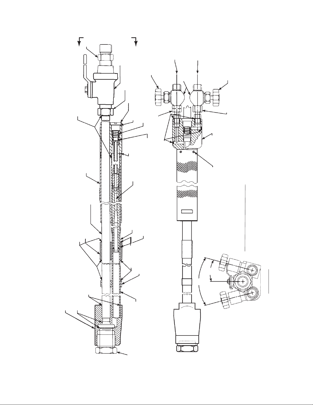
PARTS INFORMATION
SILVER BRAZE
HANDLE - 24Y28
TUBE - 20440
BRACKET - 20439
SILVER BRAZE
VALVE - 951036
ADAPTOR - 19Z86
PLUG - 134Z01
GASKET - 2114595
SILVER
BRAZE
INJECTOR
MIXER TUBE - 999898
VALVE, FG - 951001
SPRING - 28Z43
(included w/20442)
O-RING - 86W71
20442
O-RING - 187W01
(included w/20442)
FUEL GAS
ADAPTOR, FG - 999968
SILVER BRAZE
OXYGEN
ROTATED FOR DETAIL CLARITY
FOR TRUE POSITION OF
VALVES SEE END VIEW " A-A".
VALVE, OXY. - 951002
ADAPTOR, OXY -
999304
BODY - 20461
#6-32 x 5/16" SELF TAPPING
SCREW (61332996)
C-63 Heavy Duty Cutting Torch (Series A)
60" long, 180° Head - P/N 27X05 (illus.)
60" long, 75° Head - P/N 5279010
CETYLENE
WITH A
SILVER BRAZE
GAS TIGHT SEAT
HEAD (180°) - 83Z92, (75°) - 5278624
Replaceable parts are illustrated below. When ordering parts, please give both number and description (including size, where appropriate).
SILVER BRAZE
SPACER - 71Z94
MIXER TUBE - 20441
NUT - 37Z23
DO NOT USE
Longer torches up to 120" long are also available. They
require longer mixer and cutting oxygen tubes and additional
spacers. Contact your ESAB representative for more de-
tails.
15°
30°
VIEW "A-A"
5

6

ESAB Welding & Cutting Products, Florence, SC Welding Equipment
COMMUNICATION GUIDE - CUSTOMER SERVICES
A. CUSTOMER SERVICE QUESTIONS:
Order Entry Product Availability Pricing Delivery
Order Changes Saleable Goods Returns Shipping Information
Telephone: (800)362-7080 / Fax: (800) 634-7548
Telephone: (800)783-5360 / Fax: (800) 783-5362
Telephone: (800) 235-4012/ Fax: (888) 586-4670
B. ENGINEERING SERVICE: Telephone: (843) 664-4416 / Fax : (800) 446-5693
Welding Equipment Troubleshooting Hours: 7:30 AM to 5:00 PM EST
Warranty Returns Authorized Repair Stations
C. TECHNICAL SERVICE: Telephone: (800) ESAB-123/ Fax: (843) 664-4452
Part Numbers Technical Applications Hours: 8:00 AM to 5:00 PM EST
Performance Features Technical Specifications Equipment Recommendations
D. LITERATURE REQUESTS: Telephone: (843) 664-5562 / Fax: (843) 664-5548
E. WELDING EQUIPMENT REPAIRS: Telephone: (843) 664-4487 / Fax: (843) 664-5557
Repair Estimates Repair Status Hours: 7:30 AM to 3:30 PM EST
F. WELDING EQUIPMENT TRAINING:
Telephone: (843)664-4428 / Fax: (843) 679-5864
Training School Information and Registrations Hours: 7:30 AM to 4:00 PM EST
G. WELDING PROCESS ASSISTANCE:
Telephone: (800) ESAB-123 / Fax: (843) 664-4454 Hours: 7:30 AM to 4:00 PM EST
H. TECHNICAL ASST. CONSUMABLES:
Telephone : (800) 933-7070 Hours: 7:30 AM to 5:00 PM EST
Eastern Distribution Center
Central Distribution Center
Western Distribution Center
Hours: 7:30 AM to 4:00 PM EST
IF YOU DO NOT KNOW WHOM TO CALL
Telephone: (800) ESAB-123/ Fax: (843) 664-4452/ Web:http://www.esab.com
Hours: 7:30 AM to 5:00 PM EST
F-9785-L 05 / 2009 Printed in U.S.A.
 Loading...