

Page 1
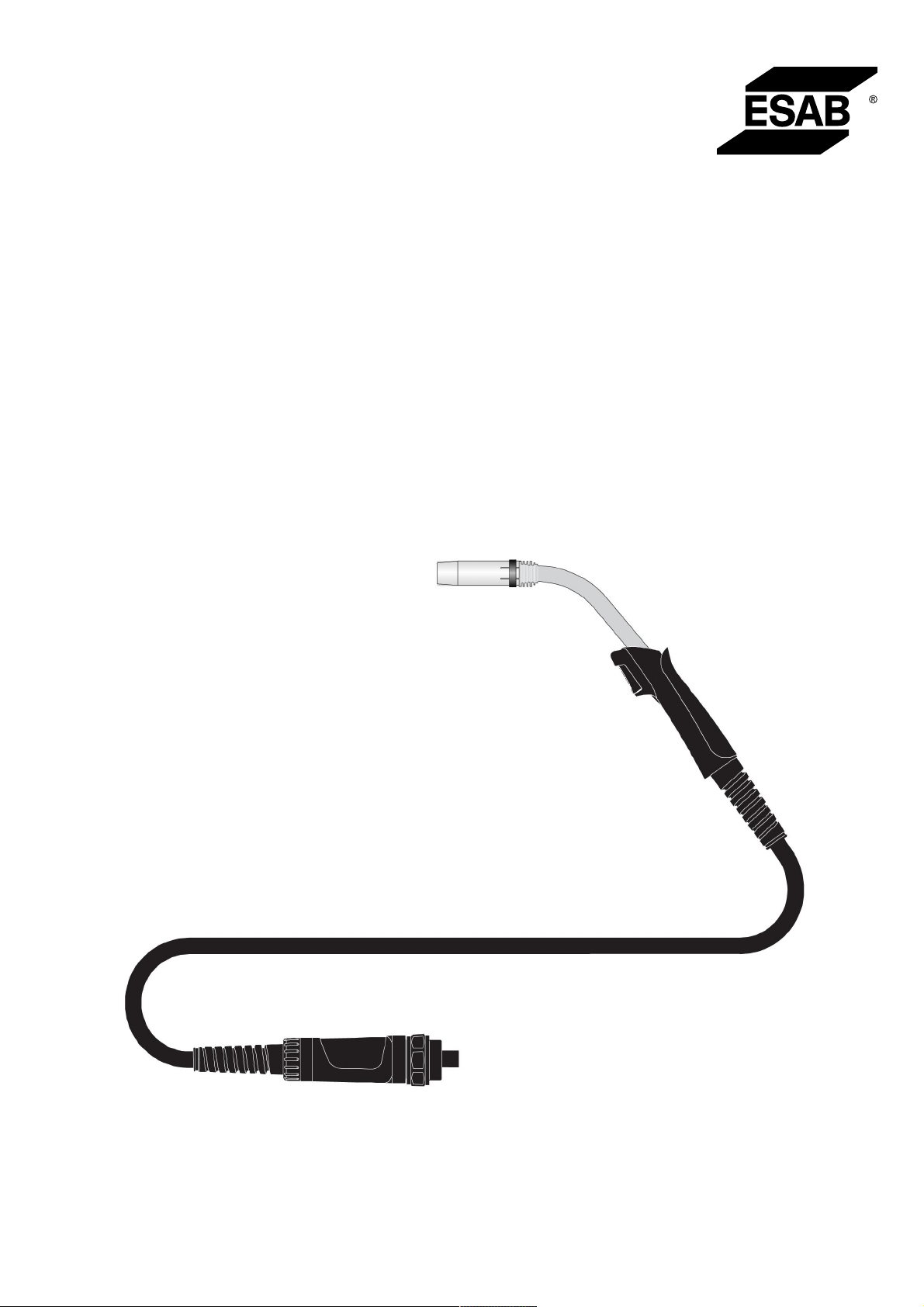
MXL™150v,MXL™200,
MXL™270,MXL™340
Instruction manual
0459 560 101 GB 20170322
Page 2
Page 3

TABLE OF CONTENTS
1
SAFETY .........................................................................................................
1.1 Meaning of symbols .................................................................................
1.2 Safety precautions ...................................................................................
2
INTRODUCTION............................................................................................
3
SHIPMENT AND PACKAGING .....................................................................
4
TECHNICAL DATA ........................................................................................
5
OPERATION ..................................................................................................
5.1 Fitting the liner..........................................................................................
5.2 Assembling the swan neck .....................................................................
5.3 Fitting the central adaptor assembly to the equipment........................
5.4 Setting the level of shielding gas............................................................
5.5 Checklist ...................................................................................................
5.6 Changing wire...........................................................................................
6
MAINTENANCE.............................................................................................
6.1 Overview ...................................................................................................
6.2 Cable assembly ........................................................................................
6.3 Cleaning the wire feed .............................................................................
6.4 Spiral liner / PTFE liner ............................................................................
6.5 Cleaning the swan neck...........................................................................
4
4
4
7
8
9
10
10
10
11
11
11
11
12
12
12
12
12
13
7
FAULT-TRACING...........................................................................................
8
DISASSEMBLY AND DISPOSAL..................................................................
9
IN THE EVENT OF AN EMERGENCY ..........................................................
10
ORDERING SPARE PARTS..........................................................................
14
15
16
17
ORDERING NUMBERS ........................................................................................ 18
SPARE PARTS LIST............................................................................................. 19
WEAR PARTS....................................................................................................... 21
ACCESSORIES .................................................................................................... 23
Rights reserved to alter specifications without notice.
0459 560 101 © ESAB AB 2017
Page 4
1 SAFETY
1 SAFETY
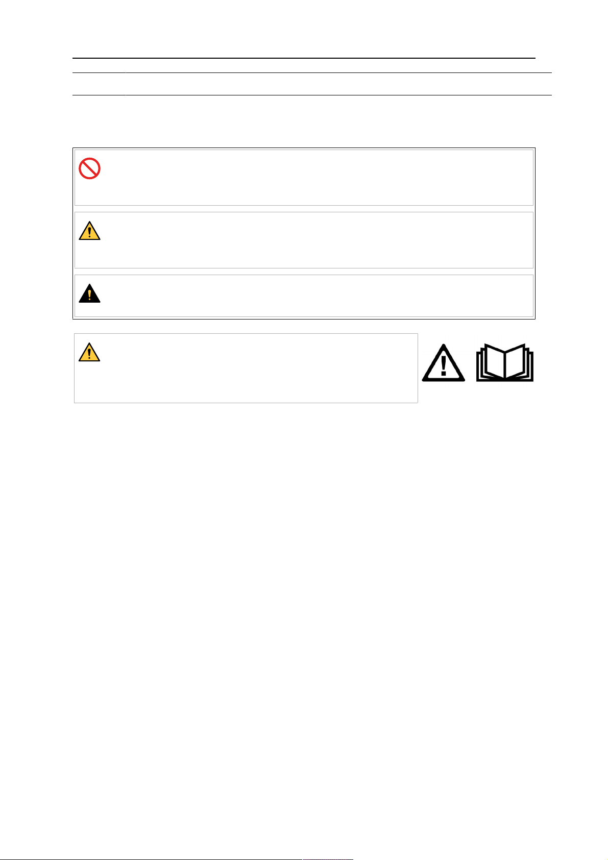
1.1 Meaning of symbols
As used throughout this manual: Means Attention! Be Alert!
DANGER!
Means immediate hazards which, if not avoided, will result in immediate,
serious personal injury or loss of life.
WARNING!
Means potential hazards which could result in personal injury or loss of
life.
CAUTION!
Means hazards which could result in minor personal injury.
WARNING!
Before use, read and understand the instruction manual
and follow all labels, employer´s safety practices and Safety
Data Sheets (SDSs).
1.2 Safety precautions
Users of ESAB equipment have the ultimate responsibility for ensuring that anyone who
works on or near the equipment observes all the relevant safety precautions. Safety
precautions must meet the requirements that apply to this type of equipment. The following
recommendations should be observed in addition to the standard regulations that apply to
the workplace.
All work must be carried out by trained personnel well-acquainted with the operation of the
equipment. Incorrect operation of the equipment may lead to hazardous situations which can
result in injury to the operator and damage to the equipment.
1. Anyone who uses the equipment must be familiar with:
○ its operation
○ location of emergency stops
○ its function
○ relevant safety precautions
○ welding and cutting or other applicable operation of the equipment
2. The operator must ensure that:
○ no unauthorised person is stationed within the working area of the equipment
when it is started up
○ no-one is unprotected when the arc is struck or work is started with the
equipment
3. The workplace must:
○ be suitable for the purpose
○ be free from drafts
0459 560 101
- 4 -
© ESAB AB 2017
Page 5
1 SAFETY
4. Personal safety equipment:
○ Always wear recommended personal safety equipment, such as safety glasses,
flame-proof clothing, safety gloves
○ Do not wear loose-fitting items, such as scarves, bracelets, rings, etc., which
could become trapped or cause burns
5. General precautions:
○ Make sure the return cable is connected securely
○ Work on high voltage equipment may only be carried out by a qualified
electrician
○ Appropriate fire extinguishing equipment must be clearly marked and close at
hand
○ Lubrication and maintenance must not be carried out on the equipment during
operation
WARNING!
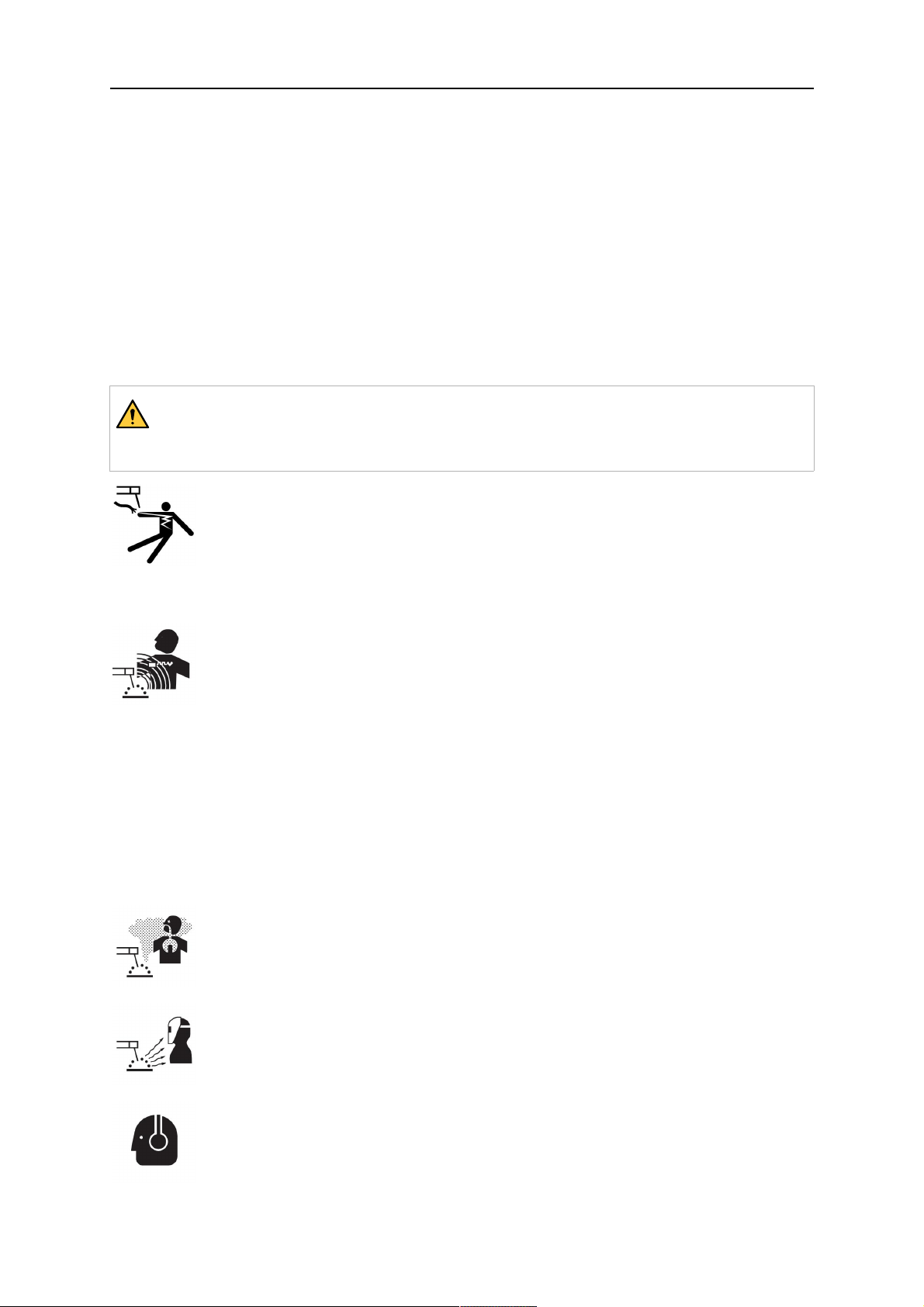
Arc welding and cutting can be injurious to yourself and others. Take precautions
when welding and cutting.
ELECTRIC SHOCK - Can kill
• Install and ground the unit in accordance with instruction manual.
• Do not touch live electrical parts or electrodes with bare skin, wet gloves or
wet clothing.
• Insulate yourself from work and ground.
• Ensure your working position is safe
ELECTRIC AND MAGNETIC FIELDS - Can be dangerous to health
• Welders having pacemakers should consult their physician before welding.
EMF may interfere with some pacemakers.
• Exposure to EMF may have other health effects which are unknown.
• Welders should use the following procedures to minimize exposure to
EMF:
○ Route the electrode and work cables together on the same side of
your body. Secure them with tape when possible. Do not place your
body between the torch and work cables. Never coil the torch or
work cable around your body. Keep welding power source and
cables as far away from your body as possible.
○ Connect the work cable to the workpiece as close as possible to the
area being welded.
FUMES AND GASES - Can be dangerous to health
• Keep your head out of the fumes.
• Use ventilation, extraction at the arc, or both, to take fumes and gases
away from your breathing zone and the general area.
ARC RAYS - Can injure eyes and burn skin
• Protect your eyes and body. Use the correct welding screen and filter lens
and wear protective clothing.
• Protect bystanders with suitable screens or curtains.
0459 560 101
NOISE - Excessive noise can damage hearing
Protect your ears. Use earmuffs or other hearing protection.
- 5 -
© ESAB AB 2017
Page 6
1 SAFETY
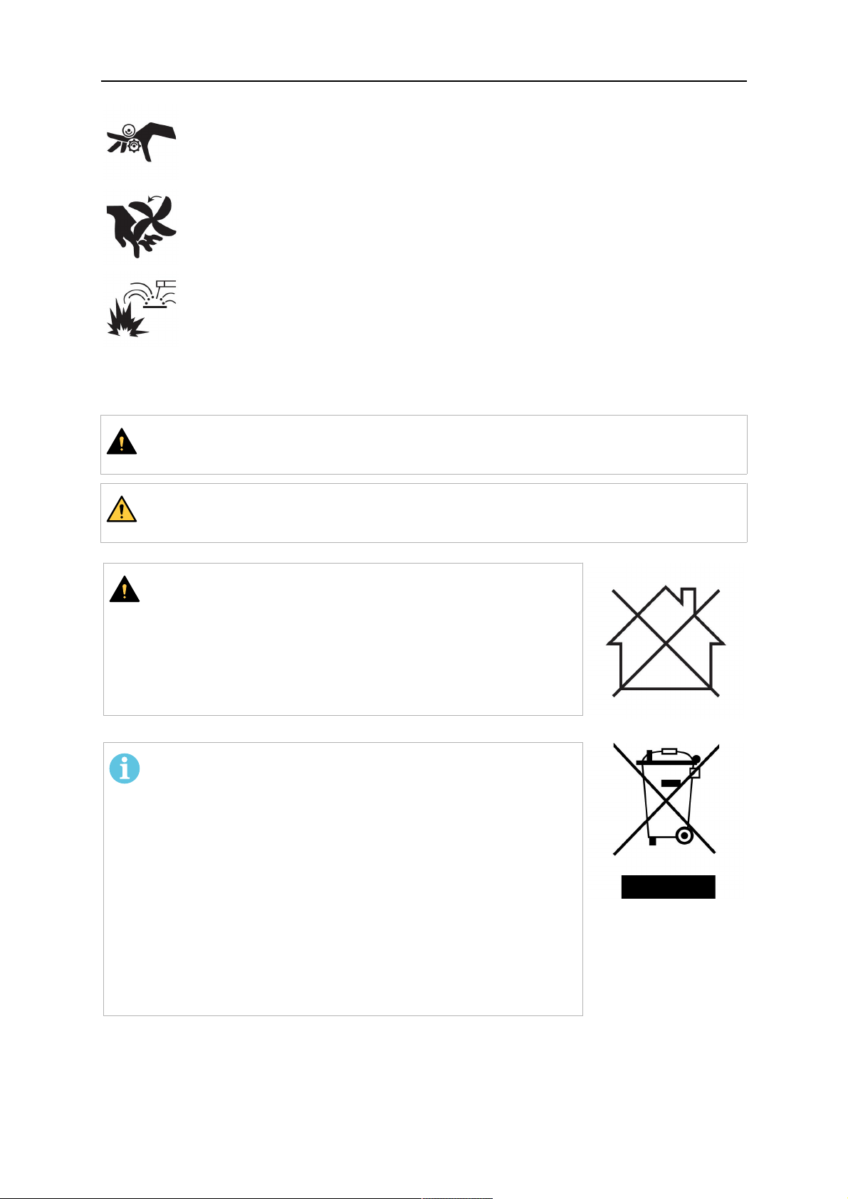
MOVING PARTS - Can cause injuries
• Keep all doors, panels and covers closed and securely in place. Have only
qualified people remove covers for maintenance and troubleshooting as
necessary. Reinstall panels or covers and close doors when service is
finished and before starting engine.
• Stop engine before installing or connecting unit.
• Keep hands, hair, loose clothing and tools away from moving parts.
FIRE HAZARD
• Sparks (spatter) can cause fire. Make sure that there are no inflammable
materials nearby.
• Do not use on closed containers.
MALFUNCTION - Call for expert assistance in the event of malfunction.
PROTECT YOURSELF AND OTHERS!
CAUTION!
This product is solely intended for arc welding.
WARNING!
Do not use the power source for thawing frozen pipes.
CAUTION!
Class A equipment is not intended for use in residential
locations where the electrical power is provided by the
public low-voltage supply system. There may be potential
difficulties in ensuring electromagnetic compatibility of class
A equipment in those locations, due to conducted as well
as radiated disturbances.
NOTE!
Dispose of electronic equipment at the recycling
facility!
In observance of European Directive 2012/19/EC on Waste
Electrical and Electronic Equipment and its implementation
in accordance with national law, electrical and/or electronic
equipment that has reached the end of its life must be
disposed of at a recycling facility.
As the person responsible for the equipment, it is your
responsibility to obtain information on approved collection
stations.
For further information contact the nearest ESAB dealer.
ESAB has an assortment of welding accessories and personal protection equipment
for purchase. For ordering information contact your local ESAB dealer or visit us on
our website.
0459 560 101
- 6 -
© ESAB AB 2017
Page 7

2 INTRODUCTION
2 INTRODUCTION
The MIG / MAG welding torches of this series are exclusively intended for shielded- arc
welding using inert gas (MIG) or active gas (MAG) for industrial and commercial use by
suitably trained employees. The torches are only available in manual versions.
0459 560 101
- 7 -
© ESAB AB 2017
Page 8

3 SHIPMENT AND PACKAGING
3 SHIPMENT AND PACKAGING
The components are carefully checked and packaged however damage may occur during
shipping.
Checking procedure on receipt of goods
Check that the shipment is correct by referring to the shipping note.
In case of damage
Check the package and components for damage (visual inspection).
In case of complaints
If the package and/or components have been damaged during shipment:
• Contact with the last carrier immediately.
• Keep the packaging (for possible inspection by the carrier or supplier, or for returningn
the goods).
Storage in an enclosed space
Ambient temperature for shipment and storage: -25°C to +55°C
Relative air humidity: up to 90% at a temperature of 20 °C
0459 560 101
- 8 -
© ESAB AB 2017
Page 9
4 TECHNICAL DATA
4 TECHNICAL DATA
Welding torch MXL 150v MXL 200 MXL 270 MXL 340
Type of cooling Air Air Air Air
Permitted load at 20% intermittence *
Carbon dioxide CO
Mixed gas, Ar/CO
2
2
150 A
150 A
Permitted load at 35% intermittence *
Carbon dioxide CO
Mixed gas, Ar/CO
2
2
Recommended gas flow 8-15
120 A 200 A 270 A 340 A
120 A 170 A 260 A 320 A
l/min
10-18
l/min
10-18
l/min
10-20
l/min
Max pressure 2.5 bar
Wire diameter 0.6-0.8 mm 0.6-1.0 mm 0.8-1.2 mm 0.8-1.2 mm
Weight
2.5 m hose package 1.1 kg − − −
3.0 m hose package − 1.6 kg 2.2 kg 2.6 kg
4.0 m hose package − 2.0 kg 2.6 kg 3.7 kg
Cable assembly
Standard length 2.5 m 3.0 m / 4.0 m 3.0 m / 4.0 m 3.0 m / 4.0 m
Standard−control cable 2−pole 2−pole 2−pole 2−pole
* The capacity my be reduced up to 30% when pulse welding.
Duty cycle
The duty cycle refers to the time as a percentage of a ten-minute period that you can weld or
cut at a certain load without overloading. The duty cycle is valid for 40°C/104°F, or below.
General torch data with reference to IEC/EN 60 974−7
Type of voltage: DC voltage
Wire type: Standard round wire
Voltage measurement: Peak value of 113V
Connection protection equipment side (EN 60
IP3X
529):
Shielding gas: CO2or Ar/CO
2
0459 560 101
- 9 -
© ESAB AB 2017
Page 10
5 OPERATION
5 OPERATION
General safety regulations for handling the equipment can be found in the "SAFETY"
chapter of this manual. Read it through before you start using the equipment!
CAUTION!
This product is intended for industrial use. In a domestic environment this product
may cause radio interference. It is the user's responsibility to take adequate
precautions.
MXL welding torches can be used in any welding position.
The torch switch in the MXL handle is suitable for 42 V, maximum 1 A.
5.1 Fitting the liner
Fit the correct wire guide liner for the application, as needed to suit the wire type and
diameter. See chapter "MAINTENANCE" section "Spiral liner / PTFE liner".
NOTE!
For information on how to install new liners and about correct assembly
procedure, see the chapter entitled “Maintenance”
Spiral liner = for steel wires
PTFE−liner = for aluminium, copper, nickel and stainless steel wires
5.2 Assembling the swan neck
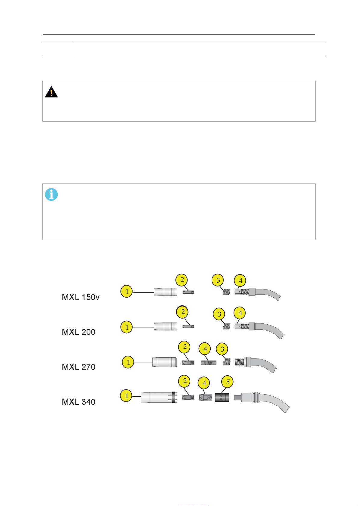
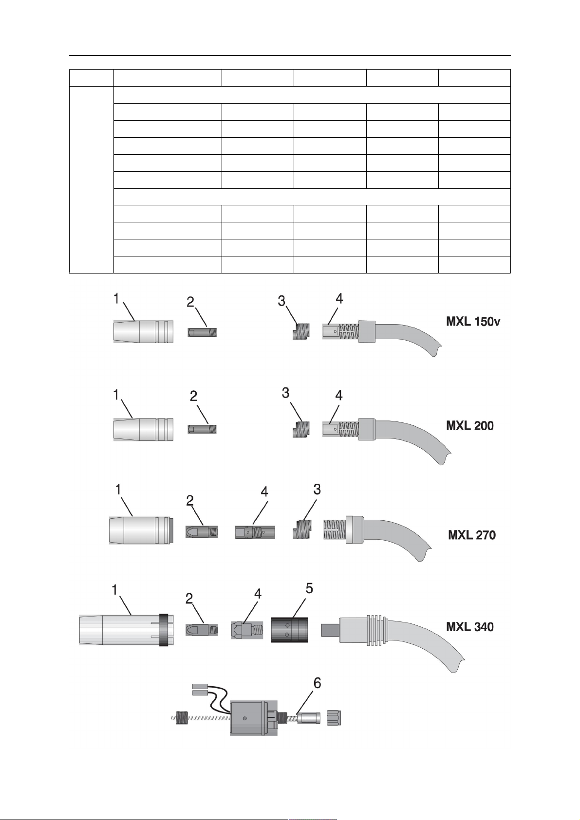
The following figures indicate how to assemble the different welding torch types.
1. Gas nozzle 4. Tip adaptor
2. Contact tip 5. Gas diffusor
3. Nozzle spring
0459 560 101
- 10 -
© ESAB AB 2017
Page 11

5 OPERATION
5.3 Fitting the central adaptor assembly to the equipment
1. Check that the wire guide liner is fitted correctly.
2. Insert the central plug into the socket on the wire feed unit and secure it by tightening
the adaptor nut firmly.
5.4 Setting the level of shielding gas
Set the quantity of gas required on the gas regulator. The type and quantity of gas to be used
depend on the welding task to be performed.
5.5 Checklist
Check the cable assembly before connecting it to the wire feed unit to confirm the wire liner
is suitable for the wire diameter and type.
Check the fixed end consumable parts on the swan neck, whether the correct contact tip etc.
is being used for the wire diameter and type.
5.6 Changing wire
When changing the wire, ensure that the end of the wire is deburred.
Insert the wire into the wire feeding unit in accordance with the operating instructions.
When inserting the wire, press the wire jog button on the wire feed unit.
0459 560 101
- 11 -
© ESAB AB 2017
Page 12
6 MAINTENANCE
6 MAINTENANCE
6.1 Overview
NOTE!
Regular maintenance is important for safe and reliable operation.
Welding torch
Cleaning and replacement of the welding torch’s wear parts should take place at regular
intervals in order to achieve trouble−free wire feed. Blow the wire guide clean regularly and
clean the contact tip.
WARNING!
Before carrying out cleaning, servicing and repair work, the following shutdown
procedure must be followed.
1. Switch off the power supply.
2. Close off the gas supply.
Make sure that the power supply and gas remain turned off all the time while
servicing the equipment.
6.2 Cable assembly
Check that all the nuts are tight.
Replace the liner if it is worn or dirty.
Replace damaged, deformed or worn parts.
6.3 Cleaning the wire feed
Disconnect the torch cable assembly from the equipment and lay it out straight.
Unscrew the nut and pull out the wire guide liner. Remove other parts from the swan neck.
Blow compressed air through the wire conduit from both ends in order to remove wire
shavings.
Insert the liner into the wire conduit and screw the nut back on.
NOTE!
New liners must be cut to the correct length. Follow the following tips and
suggestions:
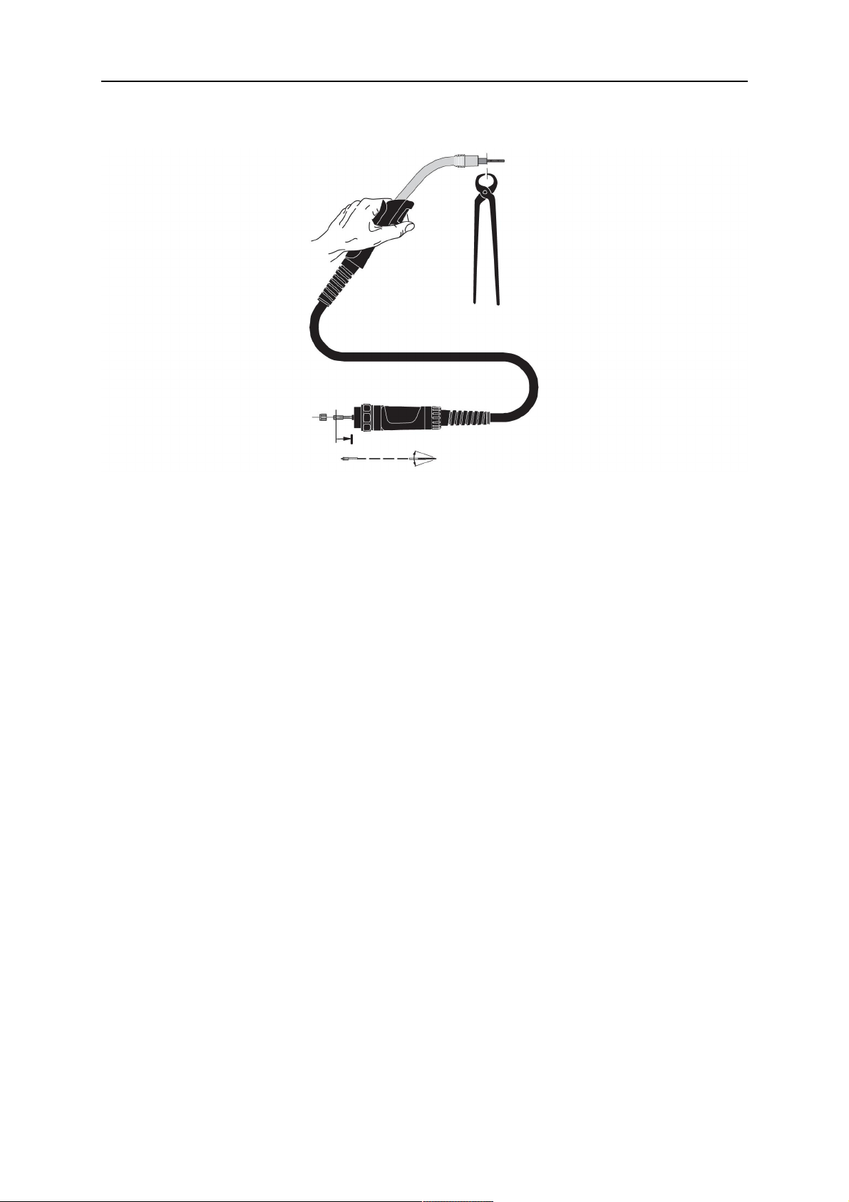
6.4 Spiral liner / PTFE liner
1. Unscrew all the fittings from the swan neck.
2. Unscrew the union nut on the central plug.
3. Remove the old liner, and then push the guide spiral liner through the hose as far as it
will go.
Make sure the cable is stretched out more or less straight.
4. Tighten the union nut by hand.
5. Cut the overhang off the spiral at the swan neck and remove the guide spiral liner
again.
6. For a smooth transition to the contact tip, grind the end of the spiral to an angle of
approx. 40°. Deburr the cutting edge.
7. Push the sharpened guide spiral liner through the hose to the holder nipple.
0459 560 101
- 12 -
© ESAB AB 2017
Page 13
6 MAINTENANCE
8. Screw the union nut into position and tighten it using the multiple spanner.
9. Screw the fittings back on again.
6.5 Cleaning the swan neck
• Clean the inside of the gas nozzle regularly to remove welding spatter and spray with
ESAB® anti-spatter agent.
• Check the consumables for visible damage and replace if necessary.
0459 560 101
- 13 -
© ESAB AB 2017
Page 14

7 FAULT-TRACING
7 FAULT-TRACING
If the measures described below are not successful, consult your dealer or the manufacturer.
Read the operating instructions for the welding components, e.g. power source and wire feed
unit.
Problem Cause Solution
Torch becomes too hot • Contact tip / Collets not
tight enough
• Current connections on the
torch side and to the work
piece are loose
No switch function • Control cable
interrupted/faulty.
Wire burnt back onto the
contact tip
• Wrong parameter setting
• Worn contact tip.
Irregular wire feed • Liner blocked
• Contact tip and wire
diameter do not match one
another
• Wrong tension set on the
wire feed unit
Short arc between the gas
nozzle and workpiece
• Spatter bridge between the
contact tip and the gas
nozzle
Variable arc • Contact tip does not match
the wire diameter, or the
contact tip is worn
• Incorrect welding
parameters set
• Liner worn
• Check and tighten
• Check and tighten
• Check/repair.
• Check or correct the
setting
• Replace
• Blow through in both
directions.
• Replace contact tip
• Correct according to
manufacturer's instructions
• Clean and spray the inside
of the gas nozzle
• Check and replace the
contact tip.
• Correct the welding
parameters.
• Replace the wire guide
Porous welds • Large amount of spatter in
the gas nozzle.
• Insufficient or total lack of
gas shield
• Draught is disturbing the
shielding gas
0459 560 101
- 14 -
• Clean the gas nozzle
• Check contents of the gas
bottle/hoses and the
pressure setting
• Shield welding area with
protective screens
© ESAB AB 2017
Page 15
8 DISASSEMBLY AND DISPOSAL
8 DISASSEMBLY AND DISPOSAL
NOTE!
Dispose of electronic equipment at the recycling
facility!
In observance of European Directive 2012/19/EC on Waste
Electrical and Electronic Equipment and its implementation
in accordance with national law, electrical and/or electronic
equipment that has reached the end of its life must be
disposed of at a recycling facility.
As the person responsible for the equipment, it is your
responsibility to obtain information on approved collection
stations.
For further information contact the nearest ESAB dealer.
The welding torch system is mainly made from steel, plastics and non-ferrous metal, and
must be disposed of in accordance with local environmental regulations.
0459 560 101
- 15 -
© ESAB AB 2017
Page 16

9 IN THE EVENT OF AN EMERGENCY
9 IN THE EVENT OF AN EMERGENCY
In the event of an emergency, the power supply must be switched off immediately.
For further action in such circumstances, consult the `Power source' Instruction manual.
0459 560 101
- 16 -
© ESAB AB 2017
Page 17

10 ORDERING SPARE PARTS
10 ORDERING SPARE PARTS
MXL 150v, MXL 200, MXL 270, MXL 340 is designed and tested in accordance with the
international and European standards 60974- 7 and . It is the obligation of the service
unit which has carried out the service or repair work to make sure that the product
still conforms to the said standard.
Spare parts and wear parts can be ordered through your nearest ESAB dealer, see the back
cover of this document. When ordering, please state product type, serial number, designation
and spare part number in accordance with the spare parts list. This facilitates dispatch and
ensures correct delivery.
0459 560 101
- 17 -
© ESAB AB 2017
Page 18
ORDERING NUMBERS
ORDERING NUMBERS
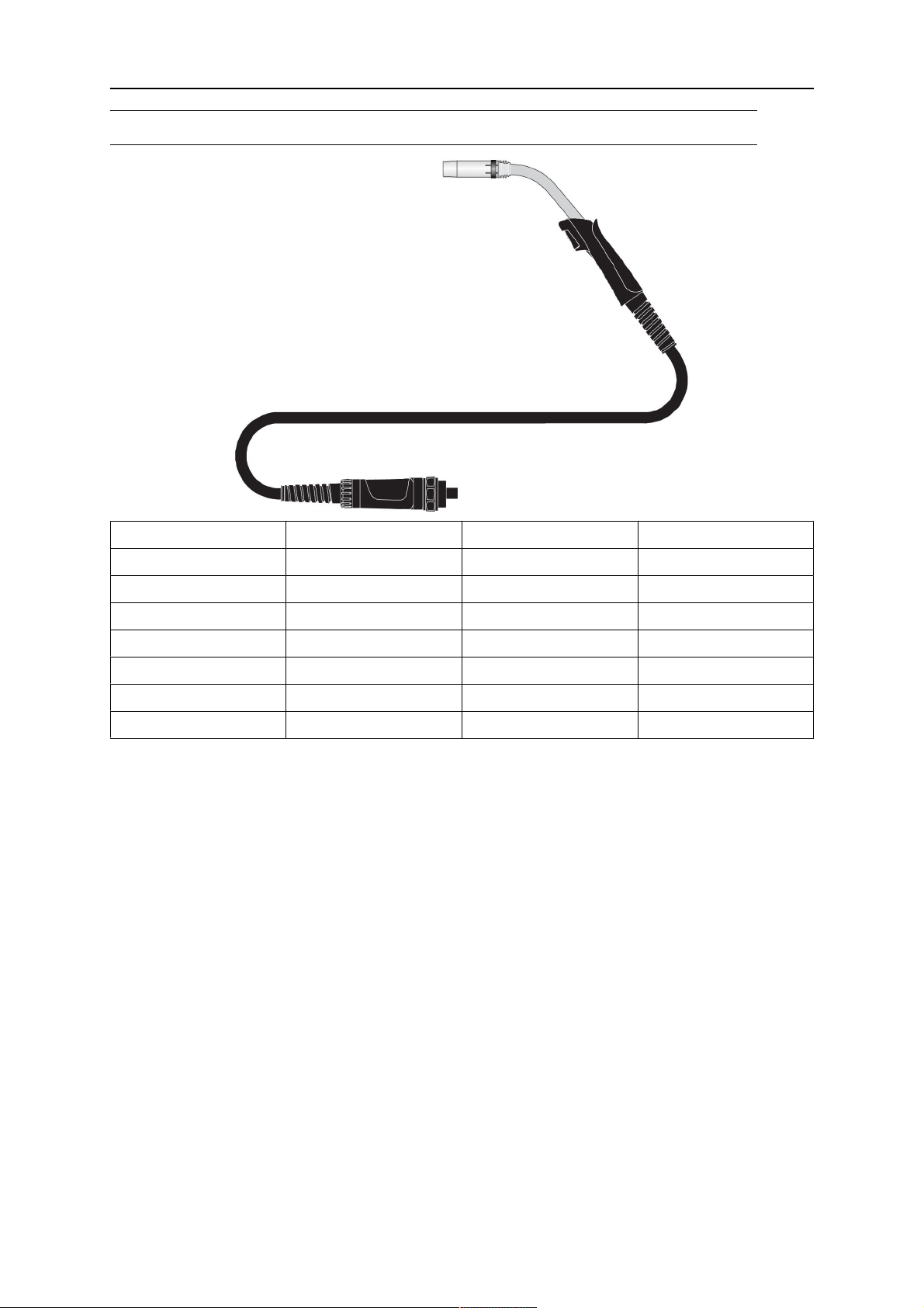
Ordering number Type Description Notes
0700 200 001 MXL™ 150v Welding torch 2.5 m with fixed connection
0700 200 002 MXL™ 200 Welding torch 3.0 m EURO Connection
0700 200 003 MXL™ 200 Welding torch 4.0 m EURO Connection
0700 200 004 MXL™ 270 Welding torch 3.0 m EURO Connection
0700 200 005 MXL™ 270 Welding torch 4.0 m EURO Connection
0700 200 006 MXL™ 340 Welding torch 3.0 m EURO Connection
0700 200 007 MXL™ 340 Welding torch 4.0 m EURO Connection
0459 560 101
- 18 -
© ESAB AB 2017
Page 19
SPARE PARTS LIST
SPARE PARTS LIST
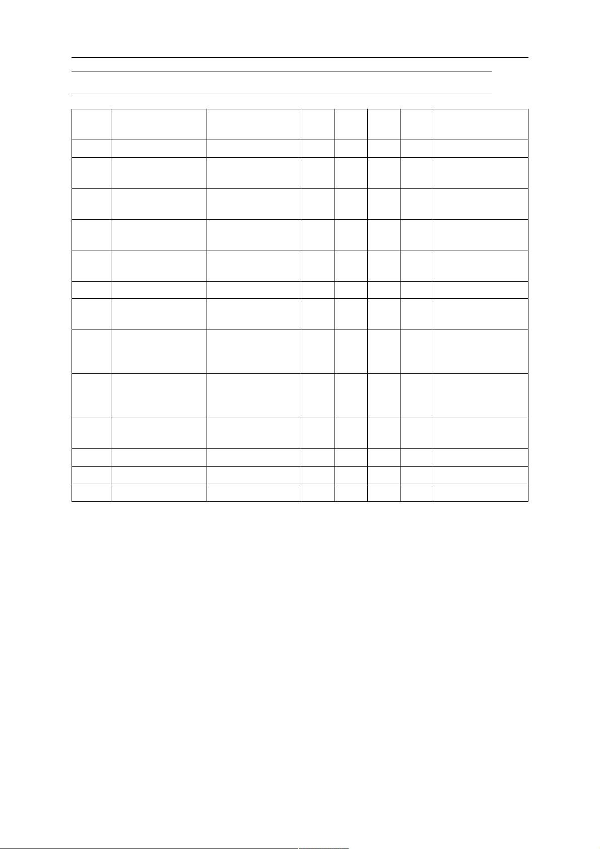
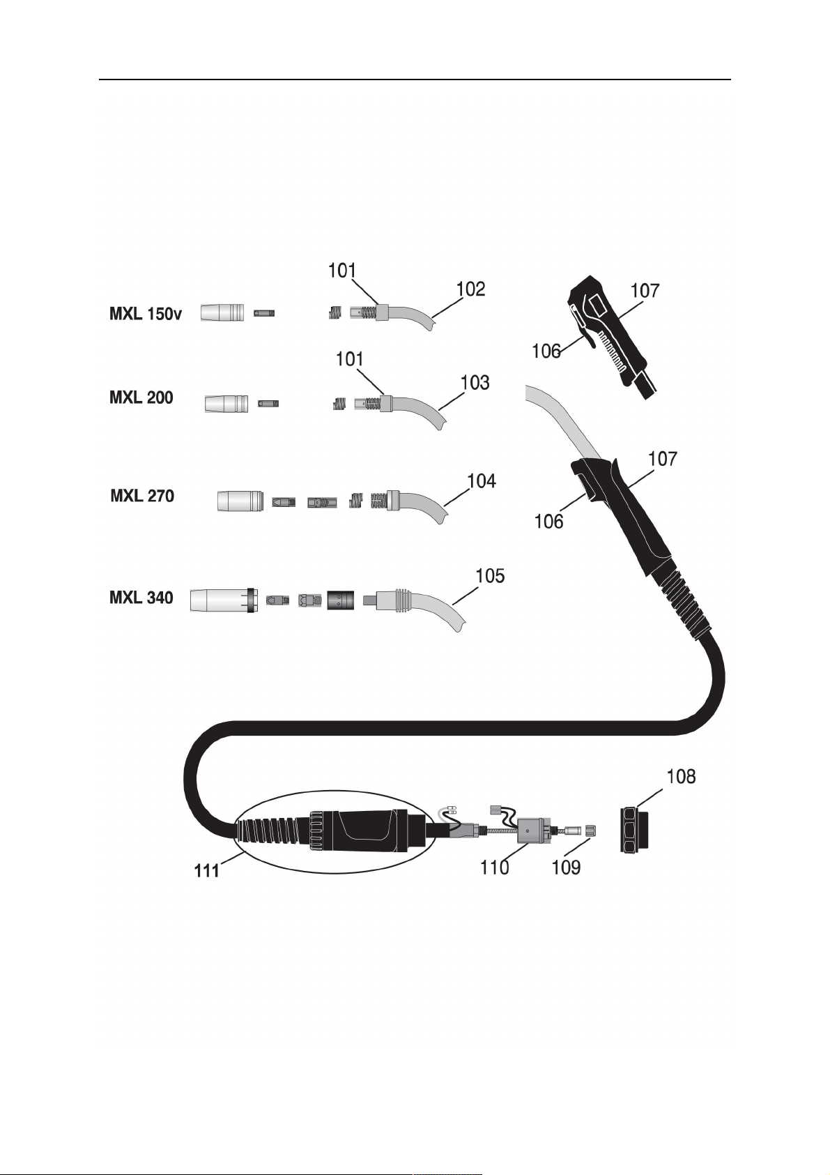
Pos Denomination Ordering no. MXL
150v
MXL
200
MXL
270
MXL
340
Notes
101 Head insulator 0700 200 096 x x
102 Swan neck
0700 200 050 x
Standard
103 Swan neck
0700 200 051 x
Standard
104 Swan neck
0700 200 052 x
Standard
105 Swan neck
0700 200 053 x
Standard
106 Trigger 2 pol 0700 200 077 x MXL 150v
106 Trigger 2 pol 0700 200 095 x x x MXL 200/ 270/
340
107 Handle complete 0700 200 093 x MXL 150v
Incl trigger pos
106
107 Handle complete 0700 200 094 x x x MXL 150v
Incl trigger pos
106
108 Adaptor nut
0700 200 097 x x x
complete
109 Liner lock nut 0700 200 098 x x x M10x1
110 Central connector 0700 200 101 x x x Incl. control leads
111 Support sleeve 0700 200 150 x x x x
0459 560 101
- 19 -
© ESAB AB 2017
Page 20
SPARE PARTS LIST
0459 560 101
- 20 -
© ESAB AB 2017
Page 21
WEAR PARTS
WEAR PARTS
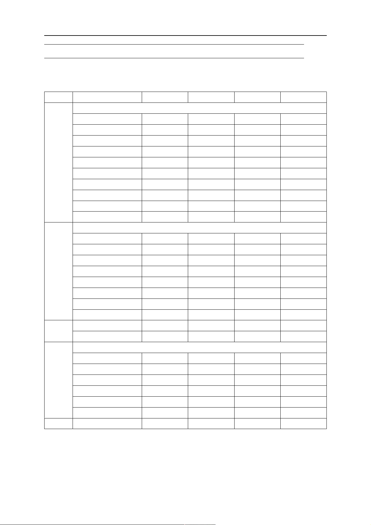
Bold = standard delivery
Item Denomination MXL™ 150v MXL™200 MXL™ 270 MXL™ 340
1 Gas nozzle
standard Ø 12 mm 0700 200 054 0700 200 054
standard Ø 15 mm 0700 200 055
standard Ø 16 mm 0700 200 056
straight Ø 16 mm 0700 200 057 0700 200 057
straight Ø 18 mm 0700 200 058
straight Ø 19 mm 0700 200 059
conical Ø 9.5 mm 0700 200 060 0700 200 060
conical Ø 11.5 mm 0700 200 061
conical Ø 12 mm 0700 200 062
Nozzle / tip insulator 0700 200 105 0700 200 105
2 Contact tip Cu
W0.6 M6x25 0700 200 063 0700 200 063
W0.8 M6x25 0700 200 064 0700 200 064
W0.9 M6x25 0700 200 065 0700 200 065
W1.0 M6x25 0700 200 066 0700 200 066
W0.8 M6x28 0700 200 068 0700 200 068
W0.9 M6x28 0700 200 069 0700 200 069
W1.0 M6x28 0700 200 070 0700 200 070
W1.2 M6x28 0700 200 071 0700 200 071
3 Nozzle spring 0700 200 078 0700 200 078
Nozzle spring 0700 200 079
4 Tip adaptor
M6, MXL 150v 0700 200 076
M6, MXL 200 0700 200 072
M6, 35 mm MXL 270 0700 200 073
M6-Alu, MXL 270 0700 200 067
M6, 28 mm MXL 340 0700 200 074
M6, 32 mm MXL 340 0700 200 075
5 Gas diffusor white 0700 200 080
0459 560 101
- 21 -
© ESAB AB 2017
Page 22
WEAR PARTS
Item Denomination MXL™ 150v MXL™200 MXL™ 270 MXL™ 340
6 Steel liner
W0.6 - W0.82.5 m 0700 200 099
W0.6 - W0.83.0 m 0700 200 085 0700 200 085 0700 200 085
W0.6 - W0.84.0 m 0700 200 086 0700 200 086 0700 200 086
W0.9 - W1.23.0 m 0700 200 087 0700 200 087 0700 200 087
W0.9 - W1.24.0 m 0700 200 088 0700 200 088 0700 200 088
PTFE liner
W0.6 - W0.83.0 m 0700 200 089 0700 200 089 0700 200 089
W0.6 - W0.84.0 m 0700 200 090 0700 200 090 0700 200 090
W0.9 - W1.23.0 m 0700 200 091 0700 200 091 0700 200 091
W0.9 - W1.24.0 m 0700 200 092 0700 200 092 0700 200 092
0459 560 101
- 22 -
© ESAB AB 2017
Page 23
ACCESSORIES
ACCESSORIES
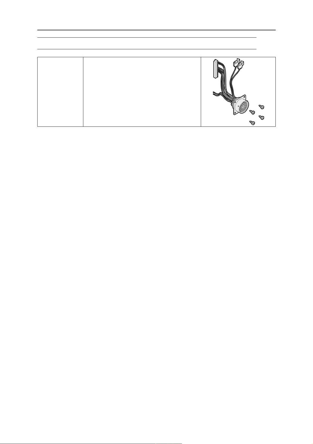
0465 451 880 Remote kit*
* The remote kit is for use together with Warrior Feed only.
0459 560 101
- 23 -
© ESAB AB 2017
Page 24
ESAB subsidiaries and representative offices
Europe
AUSTRIA
ESAB Ges.m.b.H
Vienna-Liesing
Tel: +43 1 888 25 11
Fax: +43 1 888 25 11 85
BELGIUM
S.A. ESAB N.V.
Heist-op-den-Berg
Tel: +32 15 25 79 30
Fax: +32 15 25 79 44
BULGARIA
ESAB Kft Representative Office
Sofia
Tel: +359 2 974 42 88
Fax: +359 2 974 42 88
THE CZECH REPUBLIC
ESAB VAMBERK s.r.o.
Vamberk
Tel: +420 2 819 40 885
Fax: +420 2 819 40 120
DENMARK
Aktieselskabet ESAB
Herlev
Tel: +45 36 30 01 11
Fax: +45 36 30 40 03
FINLAND
ESAB Oy
Helsinki
Tel: +358 9 547 761
Fax: +358 9 547 77 71
GREAT BRITAIN
ESAB Group (UK) Ltd
Waltham Cross
Tel: +44 1992 76 85 15
Fax: +44 1992 71 58 03
ESAB Automation Ltd
Andover
Tel: +44 1264 33 22 33
Fax: +44 1264 33 20 74
FRANCE
ESAB France S.A.
Cergy Pontoise
Tel: +33 1 30 75 55 00
Fax: +33 1 30 75 55 24
GERMANY
ESAB Welding & Cutting GmbH
Langenfeld
Tel: +49 2173 3945-0
Fax: +49 2173 3945-218
HUNGARY
ESAB Kft
Budapest
Tel: +36 1 20 44 182
Fax: +36 1 20 44 186
ITALY
ESAB Saldatura S.p.A.
Bareggio (Mi)
Tel: +39 02 97 96 8.1
Fax: +39 02 97 96 87 01
THE NETHERLANDS
ESAB Nederland B.V.
Amersfoort
Tel: +31 33 422 35 55
Fax: +31 33 422 35 44
NORWAY
AS ESAB
Larvik
Tel: +47 33 12 10 00
Fax: +47 33 11 52 03
POLAND
ESAB Sp.zo.o.
Katowice
Tel: +48 32 351 11 00
Fax: +48 32 351 11 20
PORTUGAL
ESAB Lda
Lisbon
Tel: +351 8 310 960
Fax: +351 1 859 1277
ROMANIA
ESAB Romania Trading SRL
Bucharest
Tel: +40 316 900 600
Fax: +40 316 900 601
RUSSIA
LLC ESAB
Moscow
Tel: +7 (495) 663 20 08
Fax: +7 (495) 663 20 09
SLOVAKIA
ESAB Slovakia s.r.o.
Bratislava
Tel: +421 7 44 88 24 26
Fax: +421 7 44 88 87 41
SPAIN
ESAB Ibérica S.A.
San Fernando de Henares
(MADRID)
Tel: +34 91 878 3600
Fax: +34 91 802 3461
SWEDEN
ESAB Sverige AB
Gothenburg
Tel: +46 31 50 95 00
Fax: +46 31 50 92 22
ESAB International AB
Gothenburg
Tel: +46 31 50 90 00
Fax: +46 31 50 93 60
SWITZERLAND
ESAB Europe GmbH
Baar
Tel: +41 1 741 25 25
Fax: +41 1 740 30 55
UKRAINE
ESAB Ukraine LLC
Kiev
Tel: +38 (044) 501 23 24
Fax: +38 (044) 575 21 88
North and South America
ARGENTINA
CONARCO
Buenos Aires
Tel: +54 11 4 753 4039
Fax: +54 11 4 753 6313
BRAZIL
ESAB S.A.
Contagem-MG
Tel: +55 31 2191 4333
Fax: +55 31 2191 4440
CANADA
ESAB Group Canada Inc.
Missisauga, Ontario
Tel: +1 905 670 0220
Fax: +1 905 670 4879
MEXICO
ESAB Mexico S.A.
Monterrey
Tel: +52 8 350 5959
Fax: +52 8 350 7554
USA
ESAB Welding & Cutting
Products
Florence, SC
Tel: +1 843 669 4411
Fax: +1 843 664 5748
Asia/Pacific
AUSTRALIA
ESAB South Pacific
Archerfield BC QLD 4108
Tel: +61 1300 372 228
Fax: +61 7 3711 2328
CHINA
Shanghai ESAB A/P
Shanghai
Tel: +86 21 2326 3000
Fax: +86 21 6566 6622
INDIA
ESAB India Ltd
Calcutta
Tel: +91 33 478 45 17
Fax: +91 33 468 18 80
INDONESIA
P.T. ESABindo Pratama
Jakarta
Tel: +62 21 460 0188
Fax: +62 21 461 2929
JAPAN
ESAB Japan
Tokyo
Tel: +81 45 670 7073
Fax: +81 45 670 7001
MALAYSIA
ESAB (Malaysia) Snd Bhd
USJ
Tel: +603 8023 7835
Fax: +603 8023 0225
SINGAPORE
ESAB Asia/Pacific Pte Ltd
Singapore
Tel: +65 6861 43 22
Fax: +65 6861 31 95
SOUTH KOREA
ESAB SeAH Corporation
Kyungnam
Tel: +82 55 269 8170
Fax: +82 55 289 8864
UNITED ARAB EMIRATES
ESAB Middle East FZE
Dubai
Tel: +971 4 887 21 11
Fax: +971 4 887 22 63
Africa
EGYPT
ESAB Egypt
Dokki-Cairo
Tel: +20 2 390 96 69
Fax: +20 2 393 32 13
SOUTH AFRICA
ESAB Africa Welding & Cutting
Ltd
Durbanvill 7570 - Cape Town
Tel: +27 (0)21 975 8924
Distributors
For addresses and phone
numbers to our distributors in
other countries, please visit our
home page
www.esab.com
www.esab.com
 Loading...