


Aristo®
MigU5000i
460 V
Instruction manual
0459 087 887 GB 20190927
Valid for: serial no. 950-xxx-xxxx


TABLE OF CONTENTS
1
SAFETY ....................................................................................................... 4
1.1 Meaning of symbols ............................................................................... 4
1.2 California Proposition 65 warning ........................................................ 4
1.3 Safety precautions ................................................................................. 4
1.4 User responsibility ................................................................................. 8
2
INTRODUCTION.......................................................................................... 11
2.1 Equipment ............................................................................................... 11
3
TECHNICAL DATA ...................................................................................... 12
4
INSTALLATION............................................................................................ 14
4.1 Lifting instructions ................................................................................. 14
4.2 Placing..................................................................................................... 14
4.3 Primary input .......................................................................................... 14
4.4 Terminating resistor ............................................................................... 15
4.5 Connection of multiple wire feed units ................................................ 15
5
OPERATION ................................................................................................ 18
5.1 Connections and control devices ......................................................... 19
5.2 Turning on the power source ................................................................ 19
5.3 Fan control .............................................................................................. 20
5.4 Overheating protection .......................................................................... 20
5.5 Cooling unit............................................................................................. 20
5.6 Remote control unit................................................................................ 21
6
MAINTENANCE........................................................................................... 22
6.1 Daily......................................................................................................... 22
6.2 If necessary............................................................................................. 22
6.3 Every year ............................................................................................... 23
7
FAULT TRACING......................................................................................... 24
8
ORDERING SPARE PARTS........................................................................ 25
DIAGRAM ............................................................................................................ 26
ORDERING NUMBERS ....................................................................................... 27
SPARE PARTS LIST............................................................................................ 28
ACCESSORIES ................................................................................................... 29
Rights reserved to alter specifications without notice.
0459 087 887 © ESAB AB 2019

1 SAFETY
1 SAFETY
1.1 Meaning of symbols
As used throughout this manual: Means Attention! Be Alert!
DANGER!
Means immediate hazards which, if not avoided, will result in immediate,
serious personal injury or loss of life.
WARNING!
Means potential hazards which could result in personal injury or loss of life.
CAUTION!
Means hazards which could result in minor personal injury.
WARNING!
Before use, read and understand the instruction manual
and follow all labels, employer´s safety practices and
Safety Data Sheets (SDSs).
1.2 California Proposition 65 warning
WARNING!
Welding or cutting equipment produces fumes or gases which contain chemicals
known in the State of Carlifornia to cause birth defects and, in some cases, cancer.
(California Health & Safety Code Section 25249.5 et seq.)
WARNING!
This product can expose you to chemicals including lead, which are known to the
state of California to cause cancer and birth defects or other reproductive harm.
Wash hands after use.
For more information, go to www.P65Warnings.ca.gov.
1.3 Safety precautions
WARNING!
These Safety Precautions are for your protection. They summarise precautionary
information from the references listed in Additional Safety Information section. Before
performing any installation or operating procedures, be sure to read and follow the
safety precautions listed below as well as all other manuals, material safety data
sheets, labels, etc. Failure to observe Safety Precautions can result in injury or death.
0459 087 887
- 4 -
© ESAB AB 2019

1 SAFETY
PROTECT YOURSELF AND OTHERS
Some welding, cutting and gouging processes are noisy and require
ear protection. The arc, like the sun, emits ultraviolet (UV) and other
radiation and can injure skin and eyes. Hot metal can cause burns.
Training in the proper use of the processes and equipment is essential
to prevent accidents. Therefore:
1. Wear a welding helmet fitted with a proper shade of filter to protect your face and eyes
when welding or watching.
2. Always wear safety glasses with side shields in any work area, even if welding
helmets face shields and goggles are also required.
3. Use a face shield fitted with the correct filter and cover plates to protect your eyes,
face, neck and ears from sparks and rays of the arc when operating or observing
operations. Warn bystanders not to watch the arc and not to expose themselves to the
rays of the electric-arc or hot metal.
4. Wear flameproof gauntlet type gloves, heavy long-sleeve shirt, cuff less trousers,
high-topped shoes and a welding helmet or cap for protection, to protect against arc
rays and hot sparks or hot metal. A flameproof apron may also be desirable as
protection against radiated heat and sparks.
5. Hot sparks or metal can lodge in rolled up sleeves, trouser cuffs, or pockets. Sleeves
and collars should be kept buttoned and open pockets eliminated from the front of
clothing.
6. Protect other personnel from arc rays and hot sparks with a suitable non-flammable
partition or curtains.
7. Use goggles over safety glasses when chipping slag or grinding. Chipped slag may be
hot and can fly far. Bystanders should also wear goggles over safety glasses.
FIRES AND EXPLOSIONS
Heat from flames and arcs can start fires. Hot slag or sparks can also
cause fires and explosions. Therefore:
1. Protect yourself and others from flying sparks and hot metal.
2. Remove all combustible materials well away from the work area or cover the materials
with a protective non-flammable covering. Combustible materials include wood, cloth,
sawdust, liquid and gas fuels, solvents, paints and coatings paper, etc.
3. Hot sparks or hot metal can fall through cracks or crevices in floors or wall openings
and cause a hidden smoldering fire or fires on the floor below. Make certain that such
openings are protected from hot sparks and metal.
4. Do not weld, cut or perform other hot work until the work piece has been completely
cleaned so that there are no substances on the work piece which might produce
flammable or toxic vapors. Do not do hot work on closed containers, they may
explode.
5. Have fire extinguishing equipment handy for instant use, such as a garden hose,
water pail, sand bucket, or portable fire extinguisher. Be sure you are trained in its
use.
6. Do not use equipment beyond its ratings. For example, an overloaded welding cable
can overheat and create a fire hazard.
7. After completing operations, inspect the work area to make certain there are no hot
sparks or hot metal which could cause a later fire. Use fire watchers when necessary.
0459 087 887
- 5 -
© ESAB AB 2019

1 SAFETY
ELECTRICAL SHOCK
Contact with live electrical parts and ground can cause severe injury
or death. DO NOT use AC welding current in damp areas, if movement
is confined, or if there is danger of falling. Therefore:
1. Be sure the power source frame (chassis) is connected to the ground system of the
input power.
2. Connect the workpiece to a good electrical ground.
3. Connect the work cable to the workpiece. A poor or missing connection can expose
you or others to a fatal shock.
4. Use well-maintained equipment. Replace worn or damaged cables.
5. Keep everything dry, including clothing, work area, cables, torch/electrode holder and
power source.
6. Make sure that all parts of your body are insulated from both the work piece and from
the ground.
7. Do not stand directly on metal or the earth while working in tight quarters or a damp
area; stand on dry boards or an insulating platform and wear rubber-soled shoes.
8. Put on dry, hole-free gloves before turning on the power.
9. Turn off the power before removing your gloves.
10. Refer to ANSI/ASC Standard Z49.1 for specific grounding recommendations. Do not
mistake the work lead for a ground cable.
ELECTRIC AND MAGNETIC FIELDS
May be dangerous. Electric current flowing through any conductor
causes localized Electric and Magnetic Fields (EMF). Welding and
cutting current creates EMF around welding cables and welding
machines. Therefore:
1. Welders having pacemakers should consult their physician before welding. EMF may
interfere with some pacemakers.
2. Exposure to EMF may have other health effects which are unknown.
3. Welders should use the following procedures to minimise exposure to EMF:
a) Route the electrode and work cables together. Secure them with tape when
possible.
b) Never coil the torch or work cable around your body.
c) Do not place your body between the torch and work cables. Route cables on
the same side of your body.
d) Connect the work cable to the workpiece as close as possible to the area being
welded.
e) Keep welding power source and cables as far away from your body as
possible.
FUMES AND GASES
Fumes and gases, can cause discomfort or harm, particularly in
confined spaces. Shielding gases can cause asphyxiation. Therfore:
1. Keep your head out of the fumes. Do not breathe the fumes and gases.
2. Always provide adequate ventilation in the work area by natural or mechanical means.
Do not weld, cut or gouge on materials such as galvanized steel, stainless steel,
copper, zinc, lead beryllium or cadmium unless positive mechanical ventilation is
provided. Do not breathe fumes from these materials.
0459 087 887
- 6 -
© ESAB AB 2019

1 SAFETY
3. Do not operate near degreasing and spraying operations. The heat or arc can react
with chlorinated hydrocarbon vapors to form phosgene, a highly toxic gas and other
irritant gases.
4. If you develop momentary eye, nose or throat irritation while operating, this is an
indication that ventilation is not adequate. Stop work and take necessary steps to
improve ventilation in the work area. Do not continue to operate if physical discomfort
persists.
5. Refer to ANSI/ASC Standard Z49.1 for specific ventilation recommendations.
6. WARNING: This product when used for welding or cutting, produces fumes or gases
which contain chemicals known to the State of California to cause birth defects and in
some cases cancer (California Health & Safety Code §25249.5 et seq.)
CYLINDER HANDLING
Cylinders, if mishandled, can rupture and violently release gas. A
sudden rupture of cylinder valve or relief device can injure or kill.
Therefore:
1. Locate cylinders away from heat, sparks and flames. Never strike an arc on a cylinder.
2. Use the proper gas for the process and use the proper pressure reducing regulator
designed to operate from the compressed gas cylinder. Do not use adaptors. Maintain
hoses and fittings in good condition. Follow manufacturer's operating instructions for
mounting regulator to a compressed gas cylinder.
3. Always secure cylinders in an upright position by chain or strap to suitable hand
trucks, undercarriages, benches, wall, post or racks. Never secure cylinders to work
tables or fixtures where they may become part of an electrical circuit.
4. When not in use, keep cylinder valves closed. Have valve protection cap in place if
regulator is not connected. Secure and move cylinders by using suitable hand trucks.
MOVING PARTS
Moving parts, such as fans, rotors and belts can cause
injury. Therefore:
1. Keep all doors, panels, guards and covers closed and securely in place.
2. Stop engine or drive systems before installing or connecting unit.
3. Have only qualified people remove covers for maintenance and troubleshooting as
necessary
4. To prevent accidental starting of equipment during service, disconnect negative (-)
battery cable from battery.
5. Keep hands, hair, loose clothing and tools away from moving parts.
6. Reinstall panels or covers and close doors when service is finished and before
starting engine.
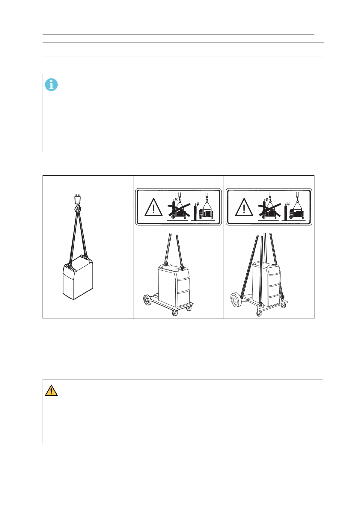
WARNING!
FALLING EQUIPMENT CAN INJURE
• Only use lifting eye to lift unit. Do NOT use running gear, gas cylinders or any
other accessories.
• Use equipment of adequate capacity to lift and support unit.
• If using lift forks to move unit, be sure forks are long enough to extend beyond
opposite side of unit.
• Keep cables and cords away from moving vehicles when working from an
aerial location.
0459 087 887
- 7 -
© ESAB AB 2019

1 SAFETY
WARNING!
EQUIPMENT MAINTENANCE
Faulty or improperly maintained equipment can cause injury or death.
Therefore:
CAUTION!
ADDITIONAL SAFETY INFORMATION
1. Always have qualified personnel perform the installation, troubleshooting and
maintenance work. Do not perform any electrical work unless you are
qualified to perform such work.
2. Before performing any maintenance work inside a power source, disconnect
the power source from the incoming electrical power.
3. Maintain cables, earthing wire, connections, power cord and power supply in
safe working order. Do not operate any equipment in faulty condition.
4. Do not abuse any equipment or accessories. Keep equipment away from
heat sources such as furnaces, wet conditions such as water puddles, oil or
grease, corrosive atmospheres and inclement weather.
5. Keep all safety devices and cabinet covers in position and in good repair.
6. Use equipment only for its intended purpose. Do not modify it in any manner.
For more information on safe practices for electric arc welding and cutting
equipment, ask your supplier for a copy of “Precautions and Safe Practices for
Arc Welding, Cutting and Gouging”, Form 52-529.
The following publications are recommended to you:
1. ANSI/ASC Z49.1 - “Safety in Welding and Cutting”
2. AWS C5.5 - “Recommended Practices for Gas Tungsten Arc Welding”
3. AWS C5.6 - “Recommended Practices for Gas Metal Arc welding”
4. AWS SP - “Safe practices” - Reprint, Welding Handbook
5. ANSI/AWS F4.1 - “Recommended Safe Practices for Welding and Cutting of
Containers That Have Held Hazardous Substances”
6. OSHA 29 CFR 1910 - "Safety and health standards"
7. CSA W117.2 - "Code for safety in welding and cutting"
8. NFPA Standard 51B, “Fire Prevention During Welding, Cutting, and Other
Hot Work"
9. CGA Standard P-1, “Precautions for Safe Handling of Compressed Gases in
Cylinders”
10.ANSI Z87.1, "Occupational and Educational Personal Eye and Face
Protection Devices"
1.4 User responsibility
Users of ESAB equipment have the ultimate responsibility for ensuring that anyone who
works on or near the equipment observes all the relevant safety precautions. Safety
precautions must meet the requirements that apply to this type of equipment. The following
recommendations should be observed in addition to the standard regulations that apply to
the workplace.
All work must be carried out by trained personnel well-acquainted with the operation of the
equipment. Incorrect operation of the equipment may lead to hazardous situations which can
result in injury to the operator and damage to the equipment.
0459 087 887
- 8 -
© ESAB AB 2019

1 SAFETY
1. Anyone who uses the equipment must be familiar with:
○ its operation
○ location of emergency stops
○ its function
○ relevant safety precautions
○ welding and cutting or other applicable operation of the equipment
2. The operator must ensure that:
○ no unauthorised person is stationed within the working area of the equipment
when it is started up
○ no-one is unprotected when the arc is struck or work is started with the
equipment
3. The workplace must:
○ be suitable for the purpose
○ be free from drafts
4. Personal safety equipment:
○ Always wear recommended personal safety equipment, such as safety glasses,
flame-proof clothing, safety gloves
○ Do not wear loose-fitting items, such as scarves, bracelets, rings, etc., which
could become trapped or cause burns
5. General precautions:
○ Make sure the return cable is connected securely
○ Work on high voltage equipment may only be carried out by a qualified
electrician
○ Appropriate fire extinguishing equipment must be clearly marked and close at
hand
○ Lubrication and maintenance must not be carried out on the equipment during
operation
WARNING!
Arc welding and cutting can be injurious to yourself and others. Take precautions
when welding and cutting.
ELECTRIC SHOCK - Can kill
• Install and ground the unit in accordance with instruction manual.
• Do not touch live electrical parts or electrodes with bare skin, wet gloves or
wet clothing.
• Insulate yourself from work and ground.
• Ensure your working position is safe
ELECTRIC AND MAGNETIC FIELDS - Can be dangerous to health
• Welders having pacemakers should consult their physician before welding.
EMF may interfere with some pacemakers.
• Exposure to EMF may have other health effects which are unknown.
• Welders should use the following procedures to minimize exposure to
EMF:
○ Route the electrode and work cables together on the same side of
your body. Secure them with tape when possible. Do not place your
body between the torch and work cables. Never coil the torch or work
cable around your body. Keep welding power source and cables as
far away from your body as possible.
○ Connect the work cable to the workpiece as close as possible to the
area being welded.
0459 087 887
- 9 -
© ESAB AB 2019

1 SAFETY
FUMES AND GASES - Can be dangerous to health
• Keep your head out of the fumes.
• Use ventilation, extraction at the arc, or both, to take fumes and gases
away from your breathing zone and the general area.
ARC RAYS - Can injure eyes and burn skin
• Protect your eyes and body. Use the correct welding screen and filter lens
and wear protective clothing.
• Protect bystanders with suitable screens or curtains.
NOISE - Excessive noise can damage hearing
Protect your ears. Use earmuffs or other hearing protection.
MOVING PARTS - Can cause injuries
• Keep all doors, panels and covers closed and securely in place. Have only
qualified people remove covers for maintenance and troubleshooting as
necessary. Reinstall panels or covers and close doors when service is
finished and before starting engine.
• Stop engine before installing or connecting unit.
• Keep hands, hair, loose clothing and tools away from moving parts.
FIRE HAZARD
• Sparks (spatter) can cause fire. Make sure that there are no inflammable
materials nearby.
• Do not use on closed containers.
HOT SURFACE - Parts can burn
• Do not touch parts bare handed.
• Allow cooling period before working on equipment.
• To handle hot parts, use proper tools and/or insulated welding gloves to
prevent burns.
MALFUNCTION - Call for expert assistance in the event of malfunction.
PROTECT YOURSELF AND OTHERS!
WARNING!
Do not use the power source for thawing frozen pipes.
CAUTION!
This product is solely intended for arc welding.
ESAB has an assortment of welding accessories and personal protection equipment
for purchase. For ordering information contact your local ESAB dealer or visit us on
our website.
0459 087 887
- 10 -
© ESAB AB 2019

2 INTRODUCTION
2 INTRODUCTION
The Mig U5000i is a GMAW/TIG welding power source, which can also be used for SMAW
(Shielded Metal Arc Welding).
The manual is valid for:
• Mig U5000i without cooling unit
• Mig U5000iw with cooling unit
NOTE!
These instructions describe a Mig U5000iw with a cooling unit.
The power source is intended for use with the Feed 3004 or Feed 4804 wire feed units.
All the settings are made from the wire feed unit or control box.
ESAB accessories for the product can be found in the "ACCESSORIES" chapter of
this manual.
2.1 Equipment
The power source is supplied complete with terminating resistor and instruction manual.
0459 087 887
- 11 -
© ESAB AB 2019

3 TECHNICAL DATA
3 TECHNICAL DATA
Mig U5000i
Mains voltage 460 V ±10%, 3~ 50/60 Hz
Mains supply S
scmin
8.7 MVA Z
0.018Ω
max
Primary current
I
GMAW (MIG/MAG)
max
I
SMAW (MMA)
max
I
GTAW (TIG)
max
33 A
34 A
26 A
No-load power demand when in energy-saving mode, 6.5 min. after welding
GTAW/GMAW (TIG/MIG) 45 W
SMAW (MMA) 55 W
Voltage/current range
GMAW (MIG/MAG) 8 - 60 V / 16 - 500 A
SMAW (MMA) 16 - 500 A
GTAW (TIG) 4 - 500 A
Permissible load at GMAW (MIG/MAG)
60 % duty cycle 500 A / 39 V
100 % duty cycle 400 A / 34 V
Permissible load SMAW (MMA)
60 % duty cycle 500 A / 40 V
100 % duty cycle 400 A / 36 V
Permissible load at GTAW (TIG)
60 % duty cycle 500 A / 30 V
100 % duty cycle 400 A / 26 V
Power factor at maximum current (I2)
SMAW (MMA) 0.91
GTAW (TIG) 0.90
GMAW (MIG/MAG) 0.90
Efficiency at maximum current (I2)
SMAW (MMA) 87 %
GTAW (TIG) 82 %
GMAW (MIG/MAG) 83 %
Open-circuit voltage U0max
GMAW (MIG/MAG), GTAW (TIG) without
VRD function
SMAW (MMA) without VRD function
U0L"Live TIG", VRD function deactivated
1)
1)
2)
72 - 88 V
68 - 80 V
79 V
GMAW (MIG/MAG), SMAW (MMA), VRD
function deactivated
0459 087 887
2)
59 V
- 12 -
© ESAB AB 2019

3 TECHNICAL DATA
VRD function activated
2)
< 35 V
Operating temperature 14 to 104 °F
(-10 to +40 °C)
Transportation temperature -4 to 131 °F
(-20 to +55 °C)
Mig U5000i
Dimensions l × w × h
without cooling unit
with cooling unit
24.6 × 15.5 × 19.5 in.
(625 × 394 × 496 mm)
24.6 × 15.5 × 30.6 in.
(625 × 394 × 776 mm)
Continual sound pressure at no-load <70 db (A)
Weight
without cooling unit
158.7 lb (72 kg)
202.8 lb (92 kg)
with cooling unit
Insulation class transformer H
Enclosure class IP23
Application class
1)
Valid for power sources without VRD specification on the rating plate.
2)
Valid for power sources with VRD specification on the rating plate. The VRD function is
explained in the instruction manuals for the control panel, if the panel has that function.
Duty cycle
The duty cycle refers to the time as a percentage of a ten-minute period that you can weld or
cut at a certain load without overloading. The duty cycle is valid for 40°C/104°F, or below.
Enclosure class
The IP code indicates the enclosure class, i.e. the degree of protection against penetration
by solid objects or water.
Equipment marked IP23 is intended for indoor and outdoor use.
Application class
The symbol indicates that the power source is designed for use in areas with increased
electrical hazard.
Cooling unit
Cooling power 2.0 kW at 104°F (40°C) temp. difference and flow
0.26gal/min
Coolant ESAB's ready mixed coolant
Coolant quantity 1.5 gal
Maximum water flow 0.6 gal/min
Maximum number of water-cooled
welding torches that may be connected
Two GMAW welding torches or
one GTAW torch and one GMAW welding torch
0459 087 887
- 13 -
© ESAB AB 2019
4 INSTALLATION
4 INSTALLATION
The installation must be carried out by a professional.
NOTE!
Mains supply requirements
This equipment complies with IEC 61000-3-12 provided that the short-circuit power is
greater than or equal to S
the public system. It is the responsibility of the installer or user of the equipment to
ensure, by consultation with the distribution network operator if necessary, that the
equipment is connected only to a supply with a short-circuit power greater than or
equal to S
. Refer to the technical data in the TECHNICAL DATA chapter.
scmin
4.1 Lifting instructions
Power source Trolley and power source Trolley 2 and power source
at the interface point between the user's supply and
scmin
4.2 Placing
Position the welding power source such that its cooling air inlets and outlets are not
obstructed.
4.3 Primary input
WARNING!
ELECTRIC SHOCK CAN KILL! PRECAUTIONARY MEASURES SHOULD BE TAKEN
TO PROVIDE MAXIMUM PROTECTION AGAINST ELECTRICAL SHOCK. BE SURE
THAT ALL POWER IS OFF BY OPENING THE LINE (WALL) DISCONNECT
SWITCH WHEN PRIMARY ELECTRICAL CONNECTIONS ARE MADE TO THE
POWER SOURCE. BE SURE TO CHECK YOUR INPUT LEADS WITH A
VOLTMETER TO MAKE SURE ALL POWER IS OFF.
0459 087 887
- 14 -
© ESAB AB 2019

4 INSTALLATION
Check that the unit is connected to the correct mains power supply
voltage, and that it is protected by the correct fuse sizes. A protective
earth connection must be made, in accordance with regulations.
Rating plate with supply connection data
Recommended fuse sizes and minimum cable areas
Mig U5000i 460 V 3~ 60 Hz
Mains voltage 460 V
Mains cable area, CU/AWG (mm2)
10(6)
Phase current, I RMS 24 A
Fuse, Time Delay 25 A
NOTE!
Sizes per National Electric Code for 90 °C rated copper conductors @ 30 °C
ambient. Not more than three conductors in raceway or cable. Local codes should
be followed if they specify larger sizes other than those listed above.
4.4 Terminating resistor
In order to avoid communication interference, the ends of the
CAN bus must be fitted with terminating resistors.
One end of the CAN bus is at the control panel, which has an
integral terminating resistor. The other end at the power
source must be fitted with the terminating resistor, as shown
on the right.
4.5 Connection of multiple wire feed units
With control unit and wire feed units without control panel (M0) it is possible to manage up to
4 wire feed units from one power source.
It is possible to choose between the following connections:
• 1 GTAW (TIG) torch and 1 GMAW (MIG/MAG) gun (Universal power source required)
• 2 GMAW (MIG/MAG) guns
• 1 GTAW (TIG) torch and 3 GMAW (MIG/MAG) guns (Universal power source required)
• 4 GMAW (MIG/MAG) guns
When welding with water-cooled GMAW guns on all wire feed units, it is recommended to
connect a separate cooling unit for the two extra guns.
We recommend connecting the guns in parallel.
0459 087 887
- 15 -
© ESAB AB 2019

4 INSTALLATION
Two wire feed units
A connection kit is required when connecting two wire feed units, see chapter
"ACCESSORIES".
A. Water connection
B. Welding current connection
C. Control box connection
Four wire feed units
Two connection kits and an extra cooling unit are required when connecting four wire feed
units, see chapter "ACCESSORIES".
0459 087 887
- 16 -
© ESAB AB 2019

4 INSTALLATION
A. Water connection
B. Welding current connection
C. Control box connection
0459 087 887
- 17 -
© ESAB AB 2019

5 OPERATION
5 OPERATION
General safety regulations for handling the equipment can be found in the "SAFETY"
chapter of this manual. Read it through before you start using the equipment!
0459 087 887
- 18 -
© ESAB AB 2019

5 OPERATION
5.1 Connections and control devices
1 Connection for cooling water from the
10 White indicating lamp - Power supply ON
GTA torch - RED
2 Connection with ELP* for cooling water
11 Orange indicating lamp - Overheating
to the GTA torch - BLUE
3 Cooling water filler 12 Connection for control cable to the wire
feed unit or to the terminating resistor
4 Connection for welding current cable (+)
13 Connection for gas hose
at SMAW or for return cable at GTAW
5 Connection for the remote control 14 Connection for welding current to the
wire feed unit
6 Connection for return cable (-) at SMAW
and GMAW or for welding current cable
15 Connection for cooling water to the wire
feed unit - BLUE
at GTAW
7 Connection for start signal from the torch 16 Connection for cooling water from the
wire feed unit - RED
8 Connection for gas to the GTA torch 17 Fuse 42 V
9 Mains power supply switch, 0 / 1 /
START
* ELP = ESAB Logic Pump, see section
"Cooling unit" in this chapter.
5.2 Turning on the power source
Turn on the mains power by turning switch (7) to the ”START” position. Release the switch,
and it will return to the ”1” position.
If the mains power supply should be interrupted while welding is in progress, and then be
restored, the power source will remain de-energised until the switch is again turned manually
to the ”START” position.
0459 087 887
- 19 -
© ESAB AB 2019

5 OPERATION
Turn the unit off by turning the switch to the ”0” position.
Whether in the event of a loss of power supply or of turning the power source off in the
normal manner, welding data will be stored so that it is available next time the unit is started.
5.3 Fan control
The power source fans continue to run for 6.5 minutes after welding has stopped, and the
unit switches to energy-saving mode. They start again when welding restarts.
The fans run at reduced speed for welding currents up to 180 A, and at full speed for higher
currents.
5.4 Overheating protection
The power source has two thermal overload trips which operate if the internal temperature
becomes too high, interrupting the welding current and lighting the orange indicating lamp on
the front of the unit. They reset automatically when the temperature has fallen.
5.5 Cooling unit
To ensure problem-free operation, the installation height from the cooling unit to the welding
torch must be max. 7 m. Heights in excess of this can cause problems, such as long starting
times, air bubbles, vacuums, etc.
If an installation height in excess of 7 m is required, we recommend an installation kit
comprising a non-return valve and a solenoid valve, refer to accessories in chapter
"ACCESSORIES". Once these valves have been installed, the hose package must be
horizontal during the initial startup so that everything fills with water. Then raise the wire feed
unit and hose package to the high height. Continued safe operation at installation heights of
up to 12 m can now commence.
Water connection (GTAW)
The cooling unit is equipped with a detection system ELP (ESAB Logic Pump) which checks
that the water hoses are connected.
The power source On/Off switch must be in the “0” position (Off) when connecting a
water-cooled GTA torch.
If a water-cooled GTA torch is connected, the water pump starts automatically when the main
On/Off switch is turned to ”START” and/or when welding starts. After welding, the pump
continues to run for 6.5 minutes, and then switches to the energy-saving mode.
Function when welding
To start welding, the welder presses the welding torch trigger switch. The power source turns
on and starts the wire feed and the cooling water pump.
To stop welding, the welder releases the welding torch trigger switch. Welding ceases, but
the cooling water pump continues to run for 6.5 minutes, after which the unit switches to
energy-saving mode.
Water flow guard
The water flow guard interrupts the welding current in the event of loss of coolant, and
displays an error message on the control panel. The water flow guard is an accessory.
0459 087 887
- 20 -
© ESAB AB 2019

5 OPERATION
5.6 Remote control unit
When the remote control unit is connected, the power source and wire feed unit are in
remote control mode; the buttons and knobs are blocked. The functions can only be adjusted
via the remote unit.
If the remote control unit is not to be used, the remote control unit must be disconnected from
the power source / wire feed unit, as otherwise it will remain in remote control mode.
For more information about the operation of the remote control unit, see the operating
instructions for the control panel.
0459 087 887
- 21 -
© ESAB AB 2019

6 MAINTENANCE
6 MAINTENANCE
NOTE!
Regular maintenance is important for safe and reliable operation.
Only those persons who have appropriate electrical knowledge (authorised personnel) may
remove the safety plates to connect or carry out service, maintenance or repair work on
welding equipment.
CAUTION!
All warranty undertakings from the supplier cease to apply if the customer attempts
any work to rectify any faults in the product during the warranty period.
6.1 Daily
Carry out the following maintenance every day.
• Check that all cables and connections are fault free. Tighten if necessary and replace
any defective parts.
• Check the water level and water flow, top up with coolant if necessary.
6.2 If necessary
• Regularly check that the power source is not clogged with dirt.
Clogged or blocked air inlets and outlets result in overheating.
• Clean the dust filter.
• Remove the fan grille with the dust
filter (1).
• Swing out the grille (2).
• Release the dust filter (3).
• Blow the filter clean with
compressed air (reduced pressure).
• Replace the filter with the finer mesh
on the side against the grille (2) (out
from the power source).
• Replace the fan grille with the dust
filter.
• Top up with coolant
ESAB's ready mixed coolant is recommended for use. See
chapter "ACCESSORIES".
• Top up with coolant until it covers half the inlet pipe.
NOTE!
Coolant must be topped up if connecting a welding torch or
connection cables that are 5 m in length or longer. When
adjusting the water level by topping up, the coolant hose
does not need to be disconnected.
0459 087 887
- 22 -
© ESAB AB 2019

6 MAINTENANCE
CAUTION!
The coolant must be handled as chemical waste.
6.3 Every year
Carry out the following maintenance at least once a year.
• Clean off any dirt and dust. Blow the power source clean with dry compressed air
(reduced pressure).
• Change the coolant and clean the hoses and water reservoir with clean water.
• Check seals, cables and connections. Tighten if necessary and replace any defective
parts.
0459 087 887
- 23 -
© ESAB AB 2019

7 FAULT TRACING
7 FAULT TRACING
Try these recommended checks and inspections before sending for an authorised service
technician.
Type of fault Action
No arc. • Check that the mains power supply
switch is turned on.
• Check that the welding current supply
and return cables are correctly
connected.
• Check that the correct current value is
set.
Welding current is interrupted during welding. • Check whether the thermal overload
trips have operated (indicated by the
orange lamp on the front panel).
• Check the main power supply fuses.
The thermal overload trips operate frequently. • Check to see whether the air filters are
clogged.
• Make sure that you are not exceeding
the rated data for the power source (i.e.
that the unit is not being overloaded).
Poor welding performance. • Check that the welding current supply
and return cables are correctly
connected.
• Check that the correct current value is
set.
• Check that the correct electrodes are
being used.
• Check the main power supply fuses.
0459 087 887
- 24 -
© ESAB AB 2019

8 ORDERING SPARE PARTS
8 ORDERING SPARE PARTS
Mig U5000i, Mig U5000iw, are designed and tested in accordance with the international and
European standards IEC/EN 60974-1/-2/-3 and EN 60974-10.
It is the obligation of the service unit which has carried out the service or repair work to
make sure that the product still conforms to the mentioned standards.
CAUTION!
Repair and electrical work should be performed by an authorised ESAB service
technician. Use only ESAB original spare and wear parts.
Spare parts and wear parts can be ordered through your nearest ESAB dealer, see
esab.com. When ordering, please state product type, serial number, designation and spare
part number in accordance with the spare parts list. This facilitates dispatch and ensures
correct delivery.
0459 087 887
- 25 -
© ESAB AB 2019

DIAGRAM
DIAGRAM
0459 087 887
- 26 -
© ESAB AB 2019

ORDERING NUMBERS
ORDERING NUMBERS
Ordering no. Denomination Product Notes
0459 230 885 Welding power
Mig U5000i
source
0459 230 886 Welding power
Mig U5000iw With cooling unit
source
0459 839 020 Spare parts list Mig 5000i, Mig U5000i,
Mig5000iWeldCloud™,
MigU5000iWeldCloud™
Technical documentation is available on the Internet at: www.esab.com
0459 087 887
- 27 -
© ESAB AB 2019

SPARE PARTS LIST
SPARE PARTS LIST
Item Ordering no. Denomination
1 0458 398 001 Filter
2 0458 383 991 Front grill
0459 087 887
- 28 -
© ESAB AB 2019

ACCESSORIES
ACCESSORIES
0458 530 880 Trolley
0458 603 880 Trolley 2 (for feeder with counterbalance
device and/or 2 gas bottles)
0458 731 880
0278 300 401
Guide pin
(B) Insulating bushing, included in guide pin
0459 145 880 Autotransformer TUA2
0459 087 887
- 29 -
© ESAB AB 2019

ACCESSORIES
0459 307 881 Handle (1 piece) with mounting screws
0459 491 910 Remote control adapter RA12 12 pole
For analogue remote controls to CAN based
equipment.
0459 491 880 Remote control unit MTA1 CAN
MIG/MAG: wire feed speed and voltage
MMA: current and arc force
TIG: current, pulse and background current
0459 491 882 Remote control unit M1 10Prog CAN
Choice of on of 10 programs
MIG/MAG: voltage deviation
TIG and MMA: current deviation
0459 491 883 Remote control unit AT1 CAN
MMA and TIG: current
0459 491 884 Remote control unit AT1 CF CAN
MMA and TIG: rough and fine setting of
current.
Remote control cable 12 pole - 4 pole
0459 554 880
5 m
0459 554 881
0459 554 882
0459 554 883
0459 554 884
0459 087 887
10 m
15 m
25 m
0.25 m
- 30 -
© ESAB AB 2019

ACCESSORIES
Connection set 12 pole - 12 pole
0456 528 880
0456 528 890
0456 528 881
0456 528 882
0456 528 883
0456 528 884
0456 528 885
0456 528 895
0456 528 886
0456 528 887
0456 528 888
0456 528 889
0459 528 970
1.7 m
5 m
10 m
15 m
25 m
35 m
Connection set water 12 pole - 12 pole
1.7 m
5 m
10 m
15 m
25 m
35 m
Connection set water
12 pole cable plug - 10 pole cable socket
1.7 m
0459 528 971
0459 528 972
0459 528 973
0459 528 974
0459 528 975
0700 006 897
5 m
10 m
15 m
25 m
35 m
Return cable 5 m 95 mm
2
0456 855 880 Water flow guard 0.7 l/min
0461 203 880 Water return flow guard Mech 7 m
0459 087 887
- 31 -
© ESAB AB 2019

ACCESSORIES
0459 579 880 MMC kit for power source Mig
0459 546 880 Connection set for connection of two wire
feed units
0414 191 881 Cooling unit OCE2H
0465 720 002 ESAB ready mixed coolant (10 l / 2.64 gal)
Use of any other cooling liquid than the
prescribed one might damage the equipment.
In case of such damage, all warranty
undertakings from ESAB cease to apply.
0459 087 887
- 32 -
© ESAB AB 2019

ACCESSORIES
0459 087 887
- 33 -
© ESAB AB 2019

ESAB AB, Lindholmsallén 9, Box 8004, 402 77 Gothenburg, Sweden, Phone +46 (0) 31 50 90 00
http://manuals.esab.com
For contact information visit esab.com
 Loading...