


Miggytrac™B501,
Miggytrac™B5001
Instruction manual
0463 404 101 GB 20181102
Valid for: B501:serialno.1847xxxx,
B5001:serialno.1847xxxx


TABLE OF CONTENTS
1
SAFETY ....................................................................................................... 5
1.1 Meaning of symbols ............................................................................... 5
2
INTRODUCTION.......................................................................................... 9
3
TECHNICAL DATA ...................................................................................... 10
4
INSTALLATION............................................................................................ 11
4.1 Assembly ................................................................................................ 11
4.2 Adjust the front arm ............................................................................... 11
4.3 Install the battery.................................................................................... 12
4.4 Torch mounting ...................................................................................... 13
4.5 Install the magnet kit (optional) ............................................................ 13
5
OPERATION ................................................................................................ 15
5.1 Weld operation........................................................................................ 15
5.2 Start and stop of the Miggytrac™ B501 tractor ................................... 15
5.3 Operation of the Miggytrac™ B5001 tractor ........................................ 16
5.3.1 Connections and control devices ......................................................... 16
5.3.2 Setting panel including colour display .................................................. 16
5.3.3 Menu selection ..................................................................................... 17
5.3.4 Selection of units of measure ............................................................... 17
5.3.5 Setting of functions............................................................................... 18
5.3.6 Installation of wire feeder ..................................................................... 20
6
MAINTENANCE........................................................................................... 21
6.1 Daily maintenance.................................................................................. 21
6.2 Weekly maintenance .............................................................................. 21
7
ORDERING SPARE PARTS ........................................................................ 22
DIMENSION DRAWING....................................................................................... 23
ORDERING NUMBERS....................................................................................... 25
ACCESSORIES ................................................................................................... 27
Rights reserved to alter specifications without notice.
0463 404 101 © ESAB AB 2018
1 SAFETY
1 SAFETY
1.1 Meaning of symbols
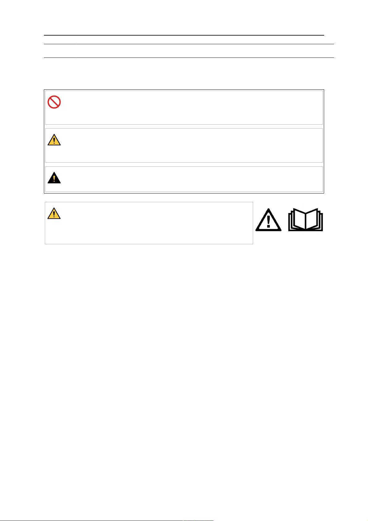
As used throughout this manual: Means Attention! Be Alert!
DANGER!
Means immediate hazards which, if not avoided, will result in immediate,
serious personal injury or loss of life.
WARNING!
Means potential hazards which could result in personal injury or loss of
life.
CAUTION!
Means hazards which could result in minor personal injury.
WARNING!
Before use, read and understand the instruction manual
and follow all labels, employer´s safety practices and Safety
Data Sheets (SDSs).
Users of ESAB equipment have the ultimate responsibility for ensuring that anyone who
works on or near the equipment observes all the relevant safety precautions. Safety
precautions must meet the requirements that apply to this type of equipment. The following
recommendations should be observed in addition to the standard regulations that apply to
the workplace.
All work must be carried out by trained personnel well-acquainted with the operation of the
equipment. Incorrect operation of the equipment may lead to hazardous situations which can
result in injury to the operator and damage to the equipment.
1. Anyone who uses the equipment must be familiar with:
○ its operation
○ location of emergency stops
○ its function
○ relevant safety precautions
○ welding and cutting or other applicable operation of the equipment
2. The operator must ensure that:
○ no unauthorised person is stationed within the working area of the equipment
when it is started up
○ no-one is unprotected when the arc is struck or work is started with the
equipment
3. The workplace must:
○ be suitable for the purpose
○ be free from drafts
0463 404 101
- 5 -
© ESAB AB 2018

1 SAFETY
4. Personal safety equipment:
○ Always wear recommended personal safety equipment, such as safety glasses,
flame-proof clothing, safety gloves
○ Do not wear loose-fitting items, such as scarves, bracelets, rings, etc., which
could become trapped or cause burns
5. General precautions:
○ Make sure the return cable is connected securely
○ Work on high voltage equipment may only be carried out by a qualified
electrician
○ Appropriate fire extinguishing equipment must be clearly marked and close at
hand
○ Lubrication and maintenance must not be carried out on the equipment during
operation
WARNING!
Arc welding and cutting can be injurious to yourself and others. Take precautions
when welding and cutting.
ELECTRIC SHOCK - Can kill
• Install and ground the unit in accordance with instruction manual.
• Do not touch live electrical parts or electrodes with bare skin, wet gloves or
wet clothing.
• Insulate yourself from work and ground.
• Ensure your working position is safe
ELECTRIC AND MAGNETIC FIELDS - Can be dangerous to health
• Welders having pacemakers should consult their physician before welding.
EMF may interfere with some pacemakers.
• Exposure to EMF may have other health effects which are unknown.
• Welders should use the following procedures to minimize exposure to
EMF:
○ Route the electrode and work cables together on the same side of
your body. Secure them with tape when possible. Do not place your
body between the torch and work cables. Never coil the torch or work
cable around your body. Keep welding power source and cables as
far away from your body as possible.
○ Connect the work cable to the workpiece as close as possible to the
area being welded.
FUMES AND GASES - Can be dangerous to health
• Keep your head out of the fumes.
• Use ventilation, extraction at the arc, or both, to take fumes and gases
away from your breathing zone and the general area.
ARC RAYS - Can injure eyes and burn skin
• Protect your eyes and body. Use the correct welding screen and filter lens
and wear protective clothing.
• Protect bystanders with suitable screens or curtains.
0463 404 101
NOISE - Excessive noise can damage hearing
Protect your ears. Use earmuffs or other hearing protection.
- 6 -
© ESAB AB 2018

1 SAFETY
MOVING PARTS - Can cause injuries
• Keep all doors, panels and covers closed and securely in place. Have only
qualified people remove covers for maintenance and troubleshooting as
necessary. Reinstall panels or covers and close doors when service is
finished and before starting engine.
• Stop engine before installing or connecting unit.
• Keep hands, hair, loose clothing and tools away from moving parts.
FIRE HAZARD
• Sparks (spatter) can cause fire. Make sure that there are no inflammable
materials nearby.
• Do not use on closed containers.
MALFUNCTION - Call for expert assistance in the event of malfunction.
PROTECT YOURSELF AND OTHERS!
CAUTION!
This product is solely intended for arc welding.
WARNING!
If the maximum operating temperature of the battery (+60 °C) is exceeded, there
is a high risk of explosion!
WARNING!
Do not use the power source for thawing frozen pipes.
CAUTION!
Class A equipment is not intended for use in residential
locations where the electrical power is provided by the
public low-voltage supply system. There may be potential
difficulties in ensuring electromagnetic compatibility of class
A equipment in those locations, due to conducted as well
as radiated disturbances.
NOTE!
Dispose of electronic equipment at the recycling
facility!
In observance of European Directive 2012/19/EC on Waste
Electrical and Electronic Equipment and its implementation
in accordance with national law, electrical and/or electronic
equipment that has reached the end of its life must be
disposed of at a recycling facility.
As the person responsible for the equipment, it is your
responsibility to obtain information on approved collection
stations.
For further information contact the nearest ESAB dealer.
0463 404 101
- 7 -
© ESAB AB 2018

1 SAFETY
ESAB has an assortment of welding accessories and personal protection equipment
for purchase. For ordering information contact your local ESAB dealer or visit us on
our website.
0463 404 101
- 8 -
© ESAB AB 2018

2 INTRODUCTION
2 INTRODUCTION
The Miggytrac™B501 and Miggytrac™B5001 are designed for MIG/MAG welding of plates
and beams.
The Miggytrac™B501 and Miggytrac™B5001 are compact tractors on which a welding
torch can be fitted. Both tractors can be powered with 18VDC from a lithium-ion battery. The
Miggytrac™B5001 can also be powered with 42VAC from a welding power source. The
tractors are equipped with four wheel drive for good traction and a high torque stepper motor
for stable welding speed. The Miggytrac™ is intended for welding with 4-stroke control mode.
As an option there is an easy fit magnet kit. The magnet kit can be attached at the bottom of
the tractor to further stabilize the movement when welding slopes up to 45°.
A battery and a battery charger are not included in the delivery, refer to the "ACCESSORIES"
chapter in this manual.
ESAB accessories for the product can be found in the "ACCESSORIES" chapter of
this manual.
0463 404 101
- 9 -
© ESAB AB 2018

3 TECHNICAL DATA
3 TECHNICAL DATA
Miggytrac™ B501 and Miggytrac™ B5001, from serial no. 1847xxxx
Miggytrac™ B501 Miggytrac™ B5001
Battery voltage (lithium-ion) 18 V DC
External supply voltage –
20–50 V AC
24–70 V DC
Battery operating time 6–8 hours 4–6 hours
Motor type Stepper motor
Welding speed
10–130cm/min
(4–51in./min)
Travel speed step welding –
Length step welding –
2–170cm/min
(1–66in./min)
250cm/min
(99in./min)
1–99cm
(0.1–19.9in.)
Crater pause – 0–5.0 s
Backfill – 0–50mm (0–2.0in.)
Preheat – 0–5.0s
Remote volt and wire feed speed – 10–95%
Mechanical adjustments:
Horizontal slide ±32 mm (±1.3in.)
Vertical slide ±40mm (±1.6in.)
Guide wheel arms ±40mm (±1.6in.)
Maximum operating temperature:
Battery +60°C (140°F)
Carriage +80°C (176°F)
Drive wheels +150°C (302°F)
Horizontal tensile force:
Without magnets 12kg (26lb)
With magnets 25kg (55lb)
Vertical tensile force at 45° with magnet 11kg (24lb)
Maximum drive angle with magnet kit 45°
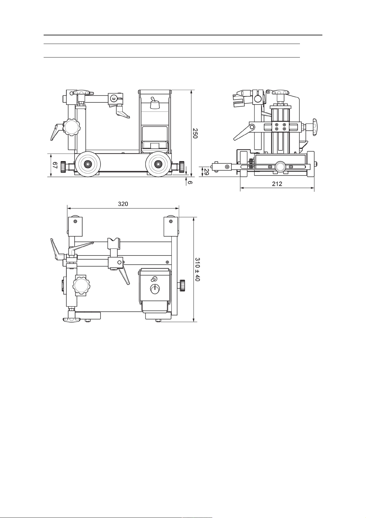
Dimensions (l×w×h)
310×290×250mm
(12.2×11.4×9.84in.)
310×290×340mm
(12.2×11.4×13.4in.)
Weight 12kg (26lb) 13kg (29lb)
0463 404 101
- 10 -
© ESAB AB 2018
4 INSTALLATION
4 INSTALLATION
The installation must be carried out by a professional.
NOTE!
The graphics in this chapter show the Miggytrac™ B501 tractor. However all
installation and adjustments are performed in the same way on the Miggytrac™
B5001 tractor, unless others are stated.
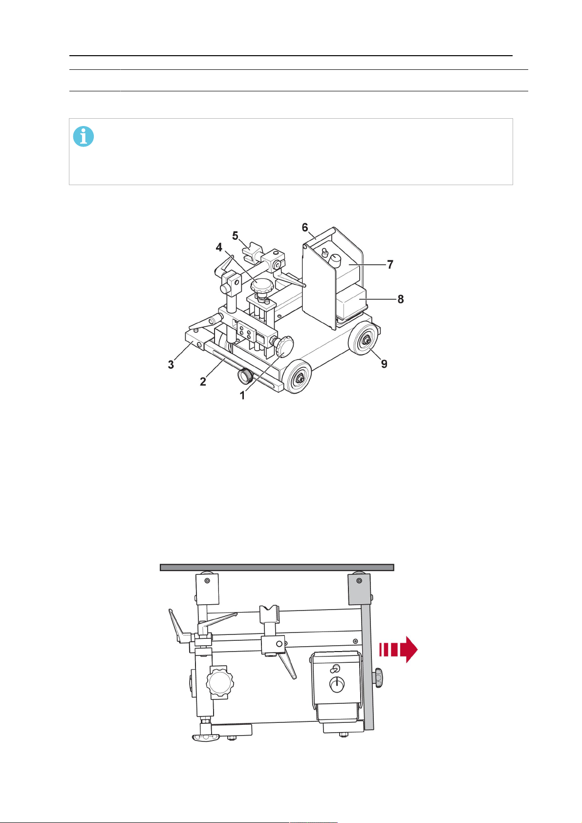
4.1 Assembly
1. Knob, horizontal adjustment 6. Handle
2. Adjustable arm 7. Control panel
3. Support wheel 8. Battery
4. Knob, vertical adjustment 9. Driving wheels
5. Connection welding torch
4.2 Adjust the front arm
Adjust the front arm to be 10 mm shorter than the rear arm, in order to make the Miggytrac™
go diagonally along the plate. This provides positive traction against the guiding structure
and the tractor maintains the desired path.
0463 404 101
- 11 -
© ESAB AB 2018

4 INSTALLATION
4.3 Install the battery
The Miggytrac™ is designed for an 18 V battery with a capacity of 4 Ah or 5 Ah.
NOTE!
Charge the battery with an approved battery charger before use.
0463 404 101
- 12 -
© ESAB AB 2018

4 INSTALLATION
4.4 Torch mounting
• Fit the welding torch to the tractor according to the graphic below.
1. Correct drive direction in combination
with the current torch position
2. Wrong drive direction in combination
with the current torch position
4.5 Install the magnet kit (optional)
A magnet kit can be installed at the bottom of the tractor to further stabilize the movement
and increase the friction between the drive wheels and the foundation.
CAUTION!
The maximum slope of the foundation is set to 45° for safety reasons.
0463 404 101
- 13 -
© ESAB AB 2018

4 INSTALLATION
0463 404 101
- 14 -
© ESAB AB 2018
5 OPERATION
5 OPERATION
5.1 Weld operation
The tractor shall be used for welding with 4-stroke control mode.
Refer to the applicable documentation for the equipment you intend to connect.
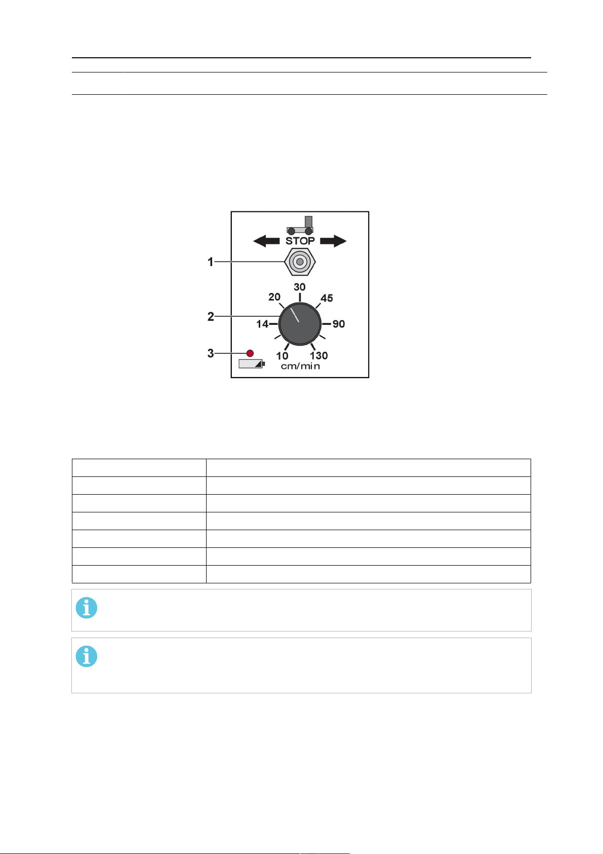
5.2 Start and stop of the Miggytrac™ B501 tractor
Start and stop the tractor with the switch (1).
Adjust the tractor travel speed with the travel speed knob (2).
The LED (3) indicates the battery charge level:
Indication Charge level
Green light 100%
Yellow light 60%
Yellow blinking light 30%
Red light 15%
Red blinking light 7%
Red rapidly blinking light 0%
NOTE!
Charge the battery after each working day.
NOTE!
Make sure to have at least two charged batteries as back-up if welding in two
shifts.
0463 404 101
- 15 -
© ESAB AB 2018

5 OPERATION
5.3 Operation of the Miggytrac™ B5001 tractor
5.3.1 Connections and control devices
1. Menu based setting panel consisting of a
graphical colour display and push buttons
2. 12-pin connector for connection to the
remote control outlet of the wire feeder.
For installation of remote adapters, see the
instruction manual for the wire feeder in
question.
5.3.2 Setting panel including colour display
1 Colour
display
2 Menu
Button is
locked 10 s
after it was
depressed
latest.
3 Start left One click: Start left without welding
4 Stop Stop tractor/welding
Graphical and digital information
Before start: Selections for programming
of all parameters
After start: Selections for programming of
certain parameters
A LED indicates the selected parameter.
Double-click: Start left welding
One click after start: Reducing the speed
In the menu: Reducing the value
0463 404 101
In the menu: Locks the menu
5 Start right One click: Start right without welding
Double-click: Start right welding
One click after start: Increasing the speed
In the menu: Increasing the value
- 16 -
© ESAB AB 2018

5 OPERATION
5.3.3 Menu selection
Stop Run with step Run without step
Welding speed X X X
Step welding off/on X
Weld length X X
Distance between welds X X
Crater time
Backfill length
Preheat
Voltage %
Wire feed speed %
1)
Pause time when the tractor stands still at the end of a step weld for power sources
1)
2)
3)
4)
4)
equipped with crater functionality
2)
Reverses at the end of a step weld to fill up a crater
3)
Delayed start of the tractor compared to welding start
4)
Remote control of voltage or wire feed speed respectively, if an ESAB wire feeder with
adapter is connected. These parameters are not available when the tractor is powered
from a battery.
X X
X X
X X X
X X
X X
5.3.4 Selection of units of measure
On Miggytrac™ B5001 there is an option to select metric
(mm and cm) or imperial/US (inch) units of measure.
The selection is made in the UNITS menu, by first
holding the Menu button depressed for 4 seconds, then
selecting the preferred units by clicking the Menu button
repeatedly.
A LED for "METRIC" or "INCH" respectively in the
display indicates the current selection.
The menu is automatically locked after 10 seconds.
0463 404 101
- 17 -
© ESAB AB 2018

5 OPERATION
5.3.5 Setting of functions
Speed
Welding speed carriage
Stitch welding
On/Off
cm or inch per minute
Off On
Length
Bead length when stitch welding
Stitch on
Stitch off
0463 404 101
- 18 -
1. Length (cm)
© ESAB AB 2018

5 OPERATION
Space
Space between each weld when stitch welding
1. Space (cm)
Crater time
The time the carriage is stationary for the power source to perform a crater function
Can also be used as a cooling time before a "backfill"
1. On
2. Off
3. Welding
4. Crater time (seconds)
Backfill
An alternative if the used power source is without crater function
Reverses at the end of the weld to fill in a crater
You can add a cooling time before the reversal, welding off, by using the crater time.
1. Backfill (mm)
2. On
3. Crater time (seconds) =>
Welding off
4. Welding
0463 404 101
- 19 -
© ESAB AB 2018

5 OPERATION
Preheat
Delayed start of carriage
1. Start
2. Welding
3. Carriage
4. Preheat
5.3.6 Installation of wire feeder
The installation must be carried out by a professional.
Miggytrac™ B5001 can be connected to one of the following wire feed units: Origo™ Feed
304, Origo™ Feed 484 or Warrior™ Feed 304
For necessary adaptation between Miggytrac™ B5001 and the used wire feed unit (including
choice of control cable), see the "ORDERING NUMBERS" appendix to this manual.
Universal feeder connection
For the operation of Miggytrac™ B5001 from other wire feeders (none ESAB), use
transformer unit and control cable according to the "ORDERING NUMBERS" appendix.
0463 404 101
- 20 -
© ESAB AB 2018

6 MAINTENANCE
6 MAINTENANCE
CAUTION!
All warranty undertakings from the supplier cease to apply if the customer
attempts any work to rectify any faults in the product during the warranty period.
6.1 Daily maintenance
• Charge the battery after each working day.
• Check the drive wheels and the guide wheels for welding spatter.
6.2 Weekly maintenance
• Clean the drive chain, the drive wheels, the guide wheels, the slide screws and the
bottom of the Miggytrac™ using compressed air.
• Lubricate the chain using a dry PTFE (Polytetrafluoroethylene) based grease or spray.
NOTE!
Use a small amount of lubrication! To much lubrication makes the outside
surface of the chain sticky and will attract dust and dirt.
0463 404 101
- 21 -
© ESAB AB 2018

7 ORDERING SPARE PARTS
7 ORDERING SPARE PARTS
CAUTION!
Repair and electrical work should be performed by an authorised ESAB service
technician. Use only ESAB original spare and wear parts.
The Miggytrac™ B501 and Miggytrac™B5001 are designed and tested in accordance with
international and european standards IEC/EN 60204-1, ISO/EN 12100-2 and IEC/EN
60974-10. On completion of service or repair work, it is the responsibility of the person(s)
performing the work to ensure that the product still complies with the requirements of the
above standard.
Spare parts and wear parts can be ordered through your nearest ESAB dealer, see
esab.com. When ordering, please state product type, serial number, designation and spare
part number in accordance with the spare parts list. This facilitates dispatch and ensures
correct delivery.
0463 404 101
- 22 -
© ESAB AB 2018
DIMENSION DRAWING
DIMENSION DRAWING
Miggytrac™B501
0463 404 101
- 23 -
© ESAB AB 2018

DIMENSION DRAWING
Miggytrac™B5001
0463 404 101
- 24 -
© ESAB AB 2018

ORDERING NUMBERS
ORDERING NUMBERS
Ordering numbers Denomination Type Notes
0457 357 882 Miggytrac™ B501 Battery excluded
0459 990 645 Miggytrac™B5001 Battery excluded
0463 404 101
- 25 -
© ESAB AB 2018

ORDERING NUMBERS
Cable key function diagram Miggytrac™ B5001
Feeder, control
panel
Cable
0457 360 880
Control cable
0457 360 886
Battery 5Ah
0457 468 074
Remote adapter
kit 0465451881
Remote adapter
kit 0459681880
Transformer
230VAC
0457 467 880
Transformer
115VAC
0457 467 882
1,2
and3:
Alternatives if the Miggytrac™ tractor cannot be powered from a welding power
source
Origo™ Feed
304/484, M12
X X X X
Origo™ Feed
304/484, M13
Origo™/ Aristo™
Feed, all panels
X
Warrior™
Feed 304
X
Universal
feeder (any
none Esab)
X
1
X
2
X
3
X
0463 404 101
- 26 -
© ESAB AB 2018
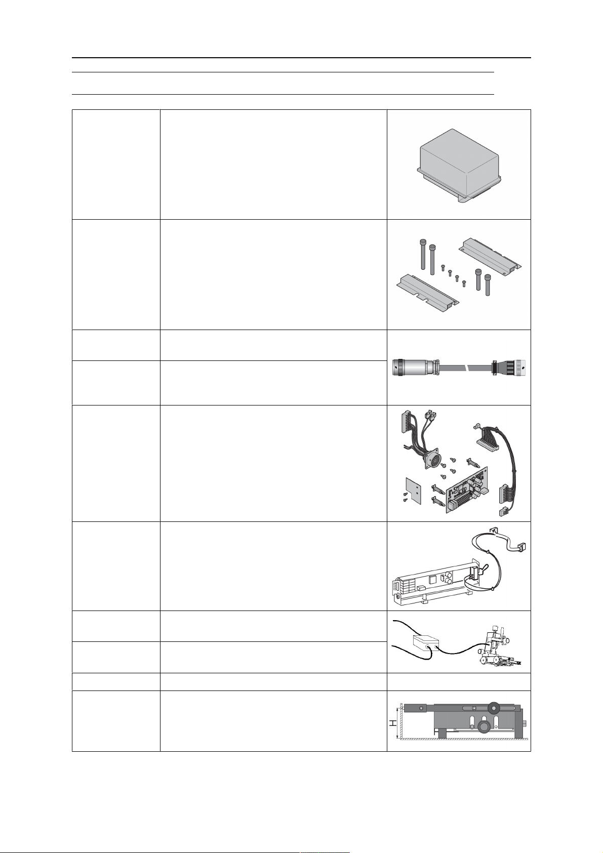
ACCESSORIES
ACCESSORIES
0457 468 074
0457 468 072
0457 468 073
Battery, Makita 18V 5 Ah
Battery charger, Makita
Battery (18 V) and battery charger kit, Makita
0457 357 131 Magnet kit
0457 360 880 Control cable Miggytrac™/Railtrac 5m.
Suitable for all ESAB feeders.
0457 360 886 Connection cable universal (only with
12-pin).
Only for use with NON ESAB feeders.
0465 451 881 Remote adapter kit Miggytrac™/Railtrac for
Warrior™ Feed 304.
0459 681 880 Remote adapter kit RA23 CAN
Miggytrac™/Railtrac for Aristo and Origo™
Feed 3004/4804 - MA23, MA24, MA25, U6.
0457 467 880 Transformer kit 230VAC.
Only for use with NON ESAB feeders.
0457 467 882 Transformer kit 115VAC.
Only for use with NON ESAB feeders.
0398 145 106 Torch holder Ø20–30mm
0457 357 171 Adjustable guide wheel kit Miggytrac™,
Adjustable height(H): 52–75mm
(2.0–3.0in.)
0463 404 101
- 27 -
© ESAB AB 2018

ESAB AB, Lindholmsallén 9, Box 8004, 402 77 Gothenburg, Sweden, Phone +46 (0) 31 50 90 00
http://manuals.esab.com
For contact information visit esab.com
 Loading...