


Caddy®
Mig C200i
Instruction manual
0463 754 001 GB 20200203
Valid for: serial no. 026-xxx-xxxx


TABLE OF CONTENTS
1
SAFETY
1.1 Meaning of symbols
1.2 Safety precautions
1.3 User responsibility
2
INTRODUCTION
2.1 Equipment
3
TECHNICAL DATA
4
INSTALLATION
4.1 Lifting instruction
4.2 Location
4.3 Mains power supply
5
OPERATION
5.1 Connection and control devices
5.2 Operation
5.2.1 Manual mode........................................................................................ 18
5.2.2 QSet mode ........................................................................................... 18
.......................................................................................................
...............................................................................
.................................................................................
.................................................................................
..........................................................................................
...............................................................................................
......................................................................................
............................................................................................
...................................................................................
...................................................................................................
...............................................................................
................................................................................................
...........................................................
.................................................................................................
4
4
4
8
11
11
12
14
14
14
14
16
17
17
5.2.3 Unit of measurement ............................................................................ 19
5.3 Error codes
5.4 Inductance settings (Fe/SS)
5.5 Polarity change
5.6 Wire feed pressure
5.7 Replacing and inserting wire
5.7.1 Changing the feed roller groove ........................................................... 22
5.8 Shielding gas
5.9 Overheating protection
6
MAINTENANCE
6.1 Inspection and cleaning
6.2 Changing the wire liner
7
TROUBLESHOOTING
8
ORDERING SPARE PARTS
DIAGRAM
............................................................................................................
ORDERING NUMBERS
WEAR PARTS
ACCESSORIES
......................................................................................................
...................................................................................................
.............................................................................................
..................................................................
.......................................................................................
.................................................................................
.................................................................
..........................................................................................
..........................................................................
...........................................................................................
.........................................................................
..........................................................................
.................................................................................
........................................................................
.......................................................................................
19
20
20
21
21
22
22
23
23
23
24
25
26
27
28
29
Rights reserved to alter specifications without notice.
0463 754 001 © ESAB AB 2020

1 SAFETY
1 SAFETY
1.1 Meaning of symbols
As used throughout this manual: Means Attention! Be Alert!
DANGER!
Means immediate hazards which, if not avoided, will result in immediate,
serious personal injury or loss of life.
WARNING!
Means potential hazards which could result in personal injury or loss of life.
CAUTION!
Means hazards which could result in minor personal injury.
WARNING!
Before use, read and understand the instruction manual
and follow all labels, employer´s safety practices and
Safety Data Sheets (SDSs).
1.2 Safety precautions
WARNING!
These Safety Precautions are for your protection. They summarise precautionary
information from the references listed in Additional Safety Information section. Before
performing any installation or operating procedures, be sure to read and follow the
safety precautions listed below as well as all other manuals, material safety data
sheets, labels, etc. Failure to observe Safety Precautions can result in injury or death.
PROTECT YOURSELF AND OTHERS
Some welding, cutting and gouging processes are noisy and require
ear protection. The arc, like the sun, emits ultraviolet (UV) and other
radiation and can injure skin and eyes. Hot metal can cause burns.
Training in the proper use of the processes and equipment is essential
to prevent accidents. Therefore:
1. Wear a welding helmet fitted with a proper shade of filter to protect your face and eyes
when welding or watching.
2. Always wear safety glasses with side shields in any work area, even if welding
helmets face shields and goggles are also required.
3. Use a face shield fitted with the correct filter and cover plates to protect your eyes,
face, neck and ears from sparks and rays of the arc when operating or observing
operations. Warn bystanders not to watch the arc and not to expose themselves to the
rays of the electric-arc or hot metal.
4. Wear flameproof gauntlet type gloves, heavy long-sleeve shirt, cuff less trousers,
high-topped shoes and a welding helmet or cap for protection, to protect against arc
rays and hot sparks or hot metal. A flameproof apron may also be desirable as
protection against radiated heat and sparks.
0463 754 001
- 4 -
© ESAB AB 2020

1 SAFETY
5. Hot sparks or metal can lodge in rolled up sleeves, trouser cuffs, or pockets. Sleeves
and collars should be kept buttoned and open pockets eliminated from the front of
clothing.
6. Protect other personnel from arc rays and hot sparks with a suitable non-flammable
partition or curtains.
7. Use goggles over safety glasses when chipping slag or grinding. Chipped slag may be
hot and can fly far. Bystanders should also wear goggles over safety glasses.
FIRES AND EXPLOSIONS
Heat from flames and arcs can start fires. Hot slag or sparks can also
cause fires and explosions. Therefore:
1. Protect yourself and others from flying sparks and hot metal.
2. Remove all combustible materials well away from the work area or cover the materials
with a protective non-flammable covering. Combustible materials include wood, cloth,
sawdust, liquid and gas fuels, solvents, paints and coatings paper, etc.
3. Hot sparks or hot metal can fall through cracks or crevices in floors or wall openings
and cause a hidden smoldering fire or fires on the floor below. Make certain that such
openings are protected from hot sparks and metal.
4. Do not weld, cut or perform other hot work until the work piece has been completely
cleaned so that there are no substances on the work piece which might produce
flammable or toxic vapors. Do not do hot work on closed containers, they may
explode.
5. Have fire extinguishing equipment handy for instant use, such as a garden hose,
water pail, sand bucket, or portable fire extinguisher. Be sure you are trained in its
use.
6. Do not use equipment beyond its ratings. For example, an overloaded welding cable
can overheat and create a fire hazard.
7. After completing operations, inspect the work area to make certain there are no hot
sparks or hot metal which could cause a later fire. Use fire watchers when necessary.
ELECTRICAL SHOCK
Contact with live electrical parts and ground can cause severe injury
or death. DO NOT use AC welding current in damp areas, if movement
is confined, or if there is danger of falling. Therefore:
1. Be sure the power source frame (chassis) is connected to the ground system of the
input power.
2. Connect the workpiece to a good electrical ground.
3. Connect the work cable to the workpiece. A poor or missing connection can expose
you or others to a fatal shock.
4. Use well-maintained equipment. Replace worn or damaged cables.
5. Keep everything dry, including clothing, work area, cables, torch/electrode holder and
power source.
6. Make sure that all parts of your body are insulated from both the work piece and from
the ground.
7. Do not stand directly on metal or the earth while working in tight quarters or a damp
area; stand on dry boards or an insulating platform and wear rubber-soled shoes.
8. Put on dry, hole-free gloves before turning on the power.
9. Turn off the power before removing your gloves.
10. Refer to ANSI/ASC Standard Z49.1 for specific grounding recommendations. Do not
mistake the work lead for a ground cable.
0463 754 001
- 5 -
© ESAB AB 2020

1 SAFETY
ELECTRIC AND MAGNETIC FIELDS
May be dangerous. Electric current flowing through any conductor
causes localized Electric and Magnetic Fields (EMF). Welding and
cutting current creates EMF around welding cables and welding
machines. Therefore:
1. Welders having pacemakers should consult their physician before welding. EMF may
interfere with some pacemakers.
2. Exposure to EMF may have other health effects which are unknown.
3. Welders should use the following procedures to minimise exposure to EMF:
a) Route the electrode and work cables together. Secure them with tape when
possible.
b) Never coil the torch or work cable around your body.
c) Do not place your body between the torch and work cables. Route cables on
the same side of your body.
d) Connect the work cable to the workpiece as close as possible to the area being
welded.
e) Keep welding power source and cables as far away from your body as
possible.
FUMES AND GASES
Fumes and gases, can cause discomfort or harm, particularly in
confined spaces. Shielding gases can cause asphyxiation. Therfore:
1. Keep your head out of the fumes. Do not breathe the fumes and gases.
2. Always provide adequate ventilation in the work area by natural or mechanical means.
Do not weld, cut or gouge on materials such as galvanized steel, stainless steel,
copper, zinc, lead beryllium or cadmium unless positive mechanical ventilation is
provided. Do not breathe fumes from these materials.
3. Do not operate near degreasing and spraying operations. The heat or arc can react
with chlorinated hydrocarbon vapors to form phosgene, a highly toxic gas and other
irritant gases.
4. If you develop momentary eye, nose or throat irritation while operating, this is an
indication that ventilation is not adequate. Stop work and take necessary steps to
improve ventilation in the work area. Do not continue to operate if physical discomfort
persists.
5. Refer to ANSI/ASC Standard Z49.1 for specific ventilation recommendations.
6. WARNING: This product when used for welding or cutting, produces fumes or gases
which contain chemicals known to the State of California to cause birth defects and in
some cases cancer (California Health & Safety Code §25249.5 et seq.)
CYLINDER HANDLING
Cylinders, if mishandled, can rupture and violently release gas. A
sudden rupture of cylinder valve or relief device can injure or kill.
Therefore:
1. Locate cylinders away from heat, sparks and flames. Never strike an arc on a cylinder.
2. Use the proper gas for the process and use the proper pressure reducing regulator
designed to operate from the compressed gas cylinder. Do not use adaptors. Maintain
hoses and fittings in good condition. Follow manufacturer's operating instructions for
mounting regulator to a compressed gas cylinder.
0463 754 001
- 6 -
© ESAB AB 2020

1 SAFETY
3. Always secure cylinders in an upright position by chain or strap to suitable hand
trucks, undercarriages, benches, wall, post or racks. Never secure cylinders to work
tables or fixtures where they may become part of an electrical circuit.
4. When not in use, keep cylinder valves closed. Have valve protection cap in place if
regulator is not connected. Secure and move cylinders by using suitable hand trucks.
MOVING PARTS
Moving parts, such as fans, rotors and belts can cause
injury. Therefore:
1. Keep all doors, panels, guards and covers closed and securely in place.
2. Stop engine or drive systems before installing or connecting unit.
3. Have only qualified people remove covers for maintenance and troubleshooting as
necessary
4. To prevent accidental starting of equipment during service, disconnect negative (-)
battery cable from battery.
5. Keep hands, hair, loose clothing and tools away from moving parts.
6. Reinstall panels or covers and close doors when service is finished and before
starting engine.
WARNING!
FALLING EQUIPMENT CAN INJURE
• Only use lifting eye to lift unit. Do NOT use running gear, gas cylinders or any
other accessories.
• Use equipment of adequate capacity to lift and support unit.
• If using lift forks to move unit, be sure forks are long enough to extend beyond
opposite side of unit.
• Keep cables and cords away from moving vehicles when working from an
aerial location.
WARNING!
EQUIPMENT MAINTENANCE
Faulty or improperly maintained equipment can cause injury or death.
Therefore:
1. Always have qualified personnel perform the installation, troubleshooting and
maintenance work. Do not perform any electrical work unless you are
qualified to perform such work.
2. Before performing any maintenance work inside a power source, disconnect
the power source from the incoming electrical power.
3. Maintain cables, earthing wire, connections, power cord and power supply in
safe working order. Do not operate any equipment in faulty condition.
4. Do not abuse any equipment or accessories. Keep equipment away from
heat sources such as furnaces, wet conditions such as water puddles, oil or
grease, corrosive atmospheres and inclement weather.
5. Keep all safety devices and cabinet covers in position and in good repair.
6. Use equipment only for its intended purpose. Do not modify it in any manner.
0463 754 001
- 7 -
© ESAB AB 2020

1 SAFETY
CAUTION!
ADDITIONAL SAFETY INFORMATION
For more information on safe practices for electric arc welding and cutting
equipment, ask your supplier for a copy of “Precautions and Safe Practices for
Arc Welding, Cutting and Gouging”, Form 52-529.
The following publications are recommended to you:
1. ANSI/ASC Z49.1 - “Safety in Welding and Cutting”
2. AWS C5.5 - “Recommended Practices for Gas Tungsten Arc Welding”
3. AWS C5.6 - “Recommended Practices for Gas Metal Arc welding”
4. AWS SP - “Safe practices” - Reprint, Welding Handbook
5. ANSI/AWS F4.1 - “Recommended Safe Practices for Welding and Cutting of
Containers That Have Held Hazardous Substances”
6. OSHA 29 CFR 1910 - "Safety and health standards"
7. CSA W117.2 - "Code for safety in welding and cutting"
8. NFPA Standard 51B, “Fire Prevention During Welding, Cutting, and Other
Hot Work"
9. CGA Standard P-1, “Precautions for Safe Handling of Compressed Gases in
Cylinders”
10.ANSI Z87.1, "Occupational and Educational Personal Eye and Face
Protection Devices"
1.3 User responsibility
Users of ESAB equipment have the ultimate responsibility for ensuring that anyone who
works on or near the equipment observes all the relevant safety precautions. Safety
precautions must meet the requirements that apply to this type of equipment. The following
recommendations should be observed in addition to the standard regulations that apply to
the workplace.
All work must be carried out by trained personnel well-acquainted with the operation of the
equipment. Incorrect operation of the equipment may lead to hazardous situations which can
result in injury to the operator and damage to the equipment.
1. Anyone who uses the equipment must be familiar with:
○ its operation
○ location of emergency stops
○ its function
○ relevant safety precautions
○ welding and cutting or other applicable operation of the equipment
2. The operator must ensure that:
○ no unauthorised person is stationed within the working area of the equipment
when it is started up
○ no-one is unprotected when the arc is struck or work is started with the
equipment
3. The workplace must:
○ be suitable for the purpose
○ be free from drafts
0463 754 001
- 8 -
© ESAB AB 2020

1 SAFETY
4. Personal safety equipment:
○ Always wear recommended personal safety equipment, such as safety glasses,
flame-proof clothing, safety gloves
○ Do not wear loose-fitting items, such as scarves, bracelets, rings, etc., which
could become trapped or cause burns
5. General precautions:
○ Make sure the return cable is connected securely
○ Work on high voltage equipment may only be carried out by a qualified
electrician
○ Appropriate fire extinguishing equipment must be clearly marked and close at
hand
○ Lubrication and maintenance must not be carried out on the equipment during
operation
WARNING!
Arc welding and cutting can be injurious to yourself and others. Take precautions
when welding and cutting.
ELECTRIC SHOCK - Can kill
• Install and ground the unit in accordance with instruction manual.
• Do not touch live electrical parts or electrodes with bare skin, wet gloves or
wet clothing.
• Insulate yourself from work and ground.
• Ensure your working position is safe
ELECTRIC AND MAGNETIC FIELDS - Can be dangerous to health
• Welders having pacemakers should consult their physician before welding.
EMF may interfere with some pacemakers.
• Exposure to EMF may have other health effects which are unknown.
• Welders should use the following procedures to minimize exposure to
EMF:
○ Route the electrode and work cables together on the same side of
your body. Secure them with tape when possible. Do not place your
body between the torch and work cables. Never coil the torch or work
cable around your body. Keep welding power source and cables as
far away from your body as possible.
○ Connect the work cable to the workpiece as close as possible to the
area being welded.
FUMES AND GASES - Can be dangerous to health
• Keep your head out of the fumes.
• Use ventilation, extraction at the arc, or both, to take fumes and gases
away from your breathing zone and the general area.
ARC RAYS - Can injure eyes and burn skin
• Protect your eyes and body. Use the correct welding screen and filter lens
and wear protective clothing.
• Protect bystanders with suitable screens or curtains.
0463 754 001
NOISE - Excessive noise can damage hearing
Protect your ears. Use earmuffs or other hearing protection.
- 9 -
© ESAB AB 2020
1 SAFETY
MOVING PARTS - Can cause injuries
• Keep all doors, panels and covers closed and securely in place. Have only
qualified people remove covers for maintenance and troubleshooting as
necessary. Reinstall panels or covers and close doors when service is
finished and before starting engine.
• Stop engine before installing or connecting unit.
• Keep hands, hair, loose clothing and tools away from moving parts.
FIRE HAZARD
• Sparks (spatter) can cause fire. Make sure that there are no inflammable
materials nearby.
• Do not use on closed containers.
MALFUNCTION - Call for expert assistance in the event of malfunction.
PROTECT YOURSELF AND OTHERS!
WARNING!
Do not use the power source for thawing frozen pipes.
CAUTION!
This product is solely intended for arc welding.
ESAB has an assortment of welding accessories and personal protection equipment
for purchase. For ordering information contact your local ESAB dealer or visit us on
our website.
0463 754 001
- 10 -
© ESAB AB 2020

2 INTRODUCTION
2 INTRODUCTION
Mig C200i is a portable welding power source in a compact design, intended for GMA
welding.
It is possible to switch between welding with solid wire/shielding gas and welding with
selfshielded cored wire without gas.
The power source operates with wire diameters from Ø.024" to Ø.040". Pure argon, mixed
gas or pure C02may be used as shielding gases.
2.1 Equipment
The power source is supplied with:
• Instruction manual
•
Welding torch MXLTM180 (9.8 ft, fixed)
• Return cable with clamp (9.8 ft, fixed)
• Mains cable (9.8 ft m, fixed, with plug)
• Shoulder strap (see "Lifting instruction" section in "INSTALLATION" chapter).
• Gas hose with quick connection (14.8 ft)
ESAB accessories for the product can be found in the "ACCESSORIES" chapter of
this manual.
0463 754 001
- 11 -
© ESAB AB 2020

3 TECHNICAL DATA
3 TECHNICAL DATA
Mig C200i
Mains voltage 230 V, 1 ~ 50/60 Hz
Permissible load at:
25 % duty cycle 180 A
60 % duty cycle 120 A
100 % duty cycle 100 A
Setting range 30 A - 200 A
Open circuit voltage 60 V
Open circuit power 15 W
Efficiency at maximum current 82%
Power factor at maximum current 0.99
Wire feed speed 6.6 - 39.4 ft/min
Wire diameter:
Fe Ø .024" - .040"
Cored wire Ø .030" - .040"
Ss Ø .030" - .040"
Al Ø .040"
Max. diameter wire bobbin Ø7.9"
Continual sound pressure at no-load < 70 dB
Dimensions l × w × h 17.7" × 7.8" × 13.7"
Weight 26.5 lbs
Operating temperature 14 to 104°F
Transportation temperature -4 to +131°F
Enclosure class IP 23C
Application classification
Welding torch MXL 180
Cooling Air/shielding gas
Permitted load at 20 % duty cycle:
Carbon dioxide C0
Mixed gas Ar/C0
2
2
200 A
180 A
Self-shielded 120 A
Permitted load at 35 % duty cycle:
Carbon dioxide C0
Mixed gas Ar/C0
2
2
180 A
150 A
Self-shielded 100 A
Recommended gas flow 2.1 - 4.0 gallon/min (8-15 l/min)
Wire diameter .02" - .04" (0.6 - 1.0 mm)
Weight 2.9 lbs (1.32 kg)
0463 754 001
- 12 -
© ESAB AB 2020

3 TECHNICAL DATA
Welding torch MXL 180
Length cable assembly 0.1" (3.0 m)
Standard control cable 2-pole
Duty cycle
The duty cycle refers to the time as a percentage of a ten-minute period that you can weld or
cut at a certain load without overloading. The duty cycle is valid for 40°C/104°F, or below.
Enclosure class
The IP code indicates the enclosure class, i.e. the degree of protection against penetration
by solid objects or water.
Equipment marked IP23C is intended for indoor and outdoor use.
Application class
The symbol indicates that the power source is designed for use in areas with increased
electrical hazard.
0463 754 001
- 13 -
© ESAB AB 2020

4 INSTALLATION
4 INSTALLATION
The installation must be carried out by a professional.
NOTE!
Mains supply requirements
High power equipment may, due to the primary current drawn from the mains
supply, influence the power quality of the grid. Therefore connection restrictions or
requirements regarding the maximum permissible mains impedance or the required
minimum supply capacity at the interface point to the public grid may apply for some
types of equipment (see "TECHNICAL DATA" chapter). In this case it is the
responsibility of the installer or user of the equipment to ensure, by consultation with
the distribution network operator if necessary, that the equipment may be
connected.
4.1 Lifting instruction
The power source is lifted by the handle or by the shoulder strap, supplied with the power
source. The strap is fastened as shown in the picture below.
4.2 Location
Position the welding power source such a way that its cooling air inlets and outlets are not
obstructed.
4.3 Mains power supply
Check that the unit is connected to the correct mains power supply voltage, and that it is
protected by the correct fuse size. A protective earth connection must be made, in
accordance with regulations.
0463 754 001
- 14 -
© ESAB AB 2020

4 INSTALLATION
Rating plate with supply connection data
Recommended fuse sizes and minimum cable area
Mig C200i
Mains voltage
Mains cable area mm
Phase current, l
eff
Fuse anti-surge
2
230 V ±15% 1~ 50/60 Hz
3G0.60 inch
2
10 A
16 A
NOTE!
The mains cable areas and fuse sizes as shown above are in accordance with
Swedish regulations. For other regions, supply cables must be suitable for the
application and meet local and national regulations.
Extension cable
If needed, it is recommended to use an extension cable, 3G0.1inch2, of a maximum length
of 164ft.
Supply from power generators
The power source can be supplied from different types of generators. However, some
generators may not provide sufficient power for welding. The generators with AVR,
equivalent or better type of regulation with rated power 5.5 - 6.5 kW are recommended to
supply the power source within its full capacity.
It is also possible to use generators with lower rated power, starting from 3.0 kW, but in that
case the setting must be proportionally limited. The power source is protected against
undervoltage. If the power supplied by the generator is not sufficient, the welding is
interrupted. Especially the welding start could be disturbed. In case of disturbed welding
process, either adjust the welding parameters or change to a more powerful generator.
0463 754 001
- 15 -
© ESAB AB 2020

5 OPERATION
5 OPERATION
General safety regulations for handling the equipment can be found in the "SAFETY"
chapter of this manual. Read it through before you start using the equipment!
NOTE!
When moving the equipment use intended handle. Never pull on the torch.
WARNING!
Rotating parts can cause injury, take great care.
WARNING!
Assure that the side panels are closed during operation.
WARNING!
Risk of crushing when replacing the wire bobbin! Do not use safety gloves when
inserting the welding wire between the feed rollers.
WARNING!
Lock the bobbin in order to prevent
it from sliding off the hub.
0463 754 001
- 16 -
© ESAB AB 2020

5 OPERATION
5.1 Connection and control devices
1. Mains supply switch 4. Return cable
2. Display 5. Mains cable
3. Welding torch 6. Gas connection
5.2 Operation
The power source is not powered instantly when the mains switch (1) is turned on. After
approximately 2 seconds the display (2) indicates that the power source is ready.
If the welding torch trigger is pressed while the power source is being turned on, the
operation is disabled, until the trigger is released.
The return cable (4) must be reliably connected to the workpiece or to the welding table.
The side panel covering the wire feeder must be closed prior to the welding.
The power source is instantly switched off by means of the mains switch (1).
0463 754 001
- 17 -
© ESAB AB 2020

5 OPERATION
5.2.1 Manual mode
A Voltage setting
B Wire feed speed setting
C Inductance setting
D Manual/QSet mode
E Wire feed speed
F Welding current
G Welding voltage
The operator must set appropriate values for the wire feed speed and welding voltage.
5.2.2 QSet mode
A QSet value setting
B Plate thickness setting
C Material selection/
Inductance setting
D Manual/QSet mode
E Wire feed speed
F Welding current
G Welding voltage
H QSet value
I Plate thickness
In QSet mode the appropriate welding voltage is automatically set by the power source. QSet
monitors the welding arc and continuously adjusts the voltage to maintain the optimal setting.
Calibration
The first time you use QSet mode, and when you change welding wire, material or shielding
gas, you need to allow QSet to calibrate. This is done by making a test weld (min. 6
seconds). Simply start welding and let QSet find the correct parameter settings.
0463 754 001
- 18 -
© ESAB AB 2020

5 OPERATION
Material selection
Since different materials have different heat dispersion, it is necessary to select the right
material group (C) so that a correct plate thickness value can be calculated. Settings for
cored wire is done only in manual mode.
Plate thickness setting
Set the plate thickness of the object you want to weld using the plate thickness setting knob
(B). This knob sets the wire feed speed (E). A suitable voltage setting is automatically
calculated by QSet. The recommended plate thickness for the set wire feed speed is
displayed simultaneously (I). The plate thickness recommendation is calculated for a fillet
weld using the following wire dimensions: Fe/Ss and CuSi - Ø.030", Al - Ø.040". If you use a
smaller diameter wire you should set a slightly higher value for plate thickness than what you
are going to weld. If you use a larger diameter wire set a slightly lower value.
Heat input adjustment
The heat input can be adjusted with the QSet knob (A) in steps from -9 to +9 to make the
weld hotter or colder. A higher value gives a hotter, more concave, weld (longer arc length)
for more penetration. A lower value gives a colder, more convex, weld (shorter arc length) to
prevent burning through the workpiece. Typically the QSet value should be set to 0 which
gives you an average heat input that is suitable in most cases. The heat input setting is
symbolised with a thermometer indicating hotter or colder settings.
5.2.3 Unit of measurement
The setting of the unit of measurement is a hidden fuction. The default value for the power
source is mm. This can be changed to inch by pressing the pushbuttons (D) and (C) and
holding them pressed in 5 sec. With the help of the knob (B) the required unit of
measurement is selected.
5.3 Error codes
If an error occurs, only the error code will be visible.
Error No. Description Action
1 Program related error
2 Hardware related error
3 Hardware related error
Switch the equipment OFF, wait 30 sec. and switch it
ON. Call for service if the error remains.
5 Program related error
4 Thermal protection Do not switch the power source OFF, let it to cool
down.
0463 754 001
- 19 -
© ESAB AB 2020

5 OPERATION
5.4 Inductance settings (Fe/SS)
In certain cases especially for mild steel welding in different gases the quality of welding may
be improved by changing the inductance settings of the power source.
The inductance function is normally hidden, but can be invoked by the pressing and keeping
pressed the pushbutton (C) for 5 s or more. When this setting is available, all graphics from
the right side of the display disappears, and only number from 00 to 10 is displayed. This
number corresponds to the inductance value. 00 means that the inductance is low and the
welding arc is "sharp", 10 means that the inductance is high and the welding arc is "soft".
The value of the inductance can be set by means of the knob (B). Default setting is 05.
Recommendations:
• When the CO2is used it is recommended to set lower inductance then 05, for instance
from 03 down to 00
• When the Ar/CO2mixture is used, the operator should set higher inductance from 05
up to 10.
The display goes back to the regular appearance 10 s after the last movement of the knob
(B) or pressing pushbutton (C). The return to the regular mode can accelerate by again
pressing and keeping the pushbutton (C) pressed for 5 s.
5.5 Polarity change
+/- terminals
The power source is delivered with the welding wire connected to the plus pole. Some wires,
e.g. shelfshielded cored wires, are recommended to be welded with negative polarity.
Negative polarity means that the wire is connected to the minus pole and the return cable to
the plus pole. Check the recommended polarity for the welding wire you want to use.
The polarity can be changed as follows:
1. Switch off the power source and disconnect the mains cable.
2. Open the side panel.
3. Bend the rubber covers back to give access to the +/- terminals.
4. Remove the nuts and washers. Note the correct order of the washers.
5. Change the position of the cables to the desired polarity (see marking).
6. Install the washers in correct order and tighten the nuts to spanner tightness.
7. Make sure the rubber covers are covering the +/- terminals.
0463 754 001
- 20 -
© ESAB AB 2020

5 OPERATION
5.6 Wire feed pressure
Start by making sure that the wire moves smoothly through the wire guide. Then set the
pressure of the wire feeder's pressure rollers. It is important that the pressure is not too high.
Figure A Figure B
To check that the feed pressure is set correctly, you can feed out the wire against an
insulated object, e.g. a piece of wood.
When you hold the welding torch approx. 0.2” (5mm) from the piece of wood (figure A) the
feed rollers should slip.
If you hold the welding torch approx. 2” (50mm) from the piece of wood, the wire should be
fed out and bend (figure B).
5.7 Replacing and inserting wire
1. Open the side panel.
2. Place the spool on the hub and secure it with the lock.
3. Disconnect the pressure arm by folding it sidewards, the pressure roller slides away.
4. Straighten out the new wire 4"-8" cm. File away burrs and sharp edges from the end of
the wire before inserting it into the wire feeder.
5. Make sure that the wire goes properly into the feed roller groove and into the outlet
nozzle and the wire liner.
6. Secure the pressure arm.
7. Close the side panel.
Feed the wire through the welding torch until it comes out through the nozzle. This operation
should be carried out carefully, as the wire is ready for welding and an unintentional arc may
occur. Keep the torch off conducting parts during feeding the wire through and terminate wire
feeding instantly when the wire comes out.
See "TECHNICAL DATA" chapter for suitable wire dimensions for each wire type.
Use only Ø200 mm (7.9") spools.
NOTE!
Ø100 mm/1kg (Ø3.9"/2.2lbs) spools are not applicable.
WARNING!
Do not keep the torch near the ears or the face during wire feeding, as this
may result in personal injury.
0463 754 001
- 21 -
© ESAB AB 2020

5 OPERATION
NOTE!
Remember to use the correct contact tip in the welding torch for the wire diameter
used. The torch is fitted with a contact tip for Ø.030" wire. If you use another
diameter you must change the contact tip. The wire liner fitted in the torch is
recommended for welding with Fe and Ss wires. Change the liner to the PTFE type
for welding Al or Brazing (CuSi). See "Changing the wire liner" section in the
"MAINTENANCE" chapter regarding how to change the wire liner.
5.7.1 Changing the feed roller groove
The power source is delivered with the feed roller set for Ø.030/.040" welding wire. If you
want to use it for Ø.024" mm wire you must change the groove in the feed roller.
1. Fold back the pressure arm to release the pressure roller.
2. Switch on the power source and press the torch trigger to position the feed roller so
that the locking screw is visible.
3. Switch off the power source.
4. Use a 2 mm Allen key to open the locking screw about half a turn.
5. Pull the feed roller off the shaft and turn it around. See marking on the side of the feed
roller for suitable wire diameters.
6. Put the roller back on the shaft and make sure it goes all the way in. You may need to
turn the roller to position the locking screw over the flat surface of the shaft.
7. Tighten the locking screw.
5.8 Shielding gas
The choice of suitable shielding gas depends on the material. Typically mild steel is welded
with mixed gas (Ar + CO2) or carbon dioxide. Stainless steel can be welded with mixed gas
(Ar + CO2or Ar + O2) and Aluminium with pure argon. MIG/MAG brazing (CuSi) uses pure
argon or mixed gas (Ar + O2). Check the recommended gas for the welding wire you want to
use. In the QSet™ mode (see "QSet mode" section) the optimal welding arc with the gas you
use will be automatically set.
5.9 Overheating protection
Overheating is indicated on the display (2) with error code E4. A thermal overload fuse
protects the unit against overheating by disabling the welding if overheating occurs. The fuse
resets automatically when the unit has cooled down.
0463 754 001
- 22 -
© ESAB AB 2020

6 MAINTENANCE
6 MAINTENANCE
NOTE!
Regular maintenance is important for safe and reliable operation.
CAUTION!
All warranty undertakings from the supplier cease to apply if the customer attempts
any work to rectify any faults in the product during the warranty period.
6.1 Inspection and cleaning
Power source
• Check regularly that the power source is free from dirt.
• How often and which cleaning methods apply depend on: the welding process, arc
times, placement, and the surrounding environment. It is normally sufficient to blow the
dust out of the power source with dry compressed air (reduced pressure) once a year.
• Clogged or blocked air inlets and outlets otherwise result in overheating.
Welding torch
• The welding torch's wear parts should be cleaned and replaced at regular intervals in
order to achieve trouble-free wire feed. Blow the wire guide clean regularly and clean
the contact tip.
6.2 Changing the wire liner
A. Loosen the fixing screw and take the roller off the axle.
B. Loosen the adaptor nut, straighten the torch cable and remove the liner.
C. Insert the replacement liner into the straightened cable until it touches the contact tip.
D. Lock the liner with adaptor nut. Cut excess of liner so it sticks .28" out of tip adaptor.
0463 754 001
- 23 -
© ESAB AB 2020

7 TROUBLESHOOTING
7 TROUBLESHOOTING
Try these recommended checks and inspections before sending for an authorised service
technican.
Type of fault Actions
No arc • Check that the mains power supply switch is turned on.
• Check that the welding current supply and return cables
are correctly connected.
• Check that correct current value is set.
Welding current is
interrupted during welding
• Check whether the overheating protection has tripped.
(Indicated by error E4 on the display.)
• Check the main power supply fuses.
The overheating protection
trips frequently
• Check to see whether the air inlet or outlet is clogged.
• Make sure that you are not exceeding the rated data for
the power source (i.e. that the unit is not being
overloaded).
Poor welding performance • Check that the welding current supply and return cables
are correctly connected.
• Check the gas supply.
• Check that the correct current value is set.
• Check that the correct welding wires are being used.
• Check if proper rolls are applied and the pressure of the
wire feeder's pressure rollers is properly set.
0463 754 001
- 24 -
© ESAB AB 2020

8 ORDERING SPARE PARTS
8 ORDERING SPARE PARTS
CAUTION!
Repair and electrical work should be performed by an authorised ESAB service
technician. Use only ESAB original spare and wear parts.
Mig C200i is designed and tested in accordance with the international and European
standards 60974-1/-5 and 60974-10. It is the obligation of the service unit which has
carried out the service or repair work to make sure that the product still conforms to
the said standard.
Spare parts and wear parts can be ordered through your nearest ESAB dealer, see
esab.com. When ordering, please state product type, serial number, designation and spare
part number in accordance with the spare parts list. This facilitates dispatch and ensures
correct delivery.
0463 754 001
- 25 -
© ESAB AB 2020

DIAGRAM
DIAGRAM
0463 754 001
- 26 -
© ESAB AB 2020

ORDERING NUMBERS
ORDERING NUMBERS
Ordering no. Denomination Type Notes
0349 312 030 Welding power source Caddy® Mig C200i, CE 230 V, 1~ 50/60Hz
0349 300 556 Spare parts list
0463 754 001
- 27 -
© ESAB AB 2020
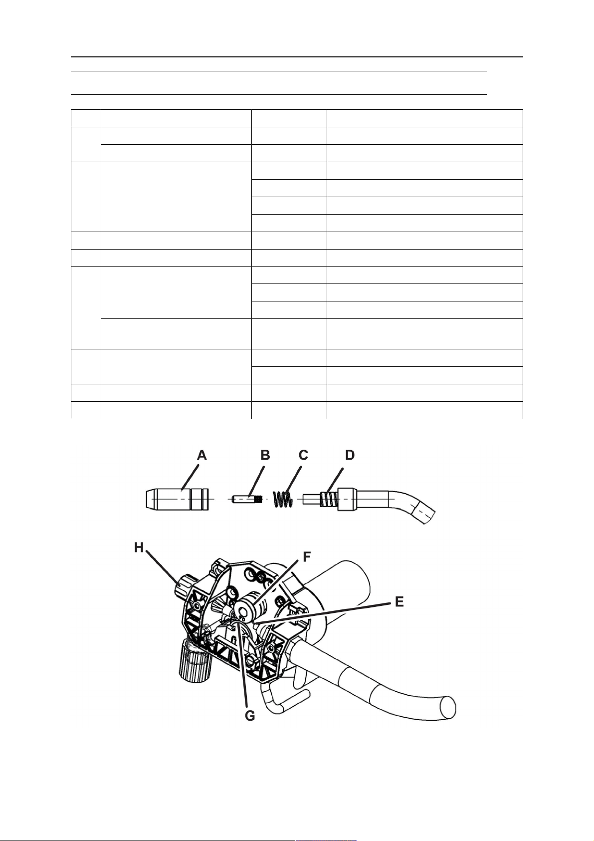
WEAR PARTS
WEAR PARTS
Item Denomination Ordering no. Notes
Gas nozzle 0700 200 054
A
Gas nozzle/Tip insulator MXL 0700 200 105
0700 200 063 W 0.6 M6x25
B Contact tip
0700 200 064 W 0.8 M6x25
0700 200 065 W 0.9 M6x25
0700 200 066 W 1.0 M6x25
C Nozzle spring 0700 200 078
D Tip adaptor 0700 200 072 Left thread
Wire liner 0700 200 085 W 0.8 - 1.0 Steel for Fe and Ss wire
0700 200 087 W 0.9 - 1.2 Steel for Fe and Ss wire
E
0700 200 091 W 0.9 - 1.2 PTFE for Al and CuSi wire
0-ring 0-ring 3.5/IDX 1.8 (3.5x1.8 mm)
Blacknitrilerubber
F Feed roller 0349 311 890 W 0.6/0.8 - 1.0 V-groove
0349 312 836 W 0.6/0.8 V-groove -1.0 U-groove
G Pressure roller 0349 312 062
H Inlet nozzle 0455 049 002 W 0.6-1.0
The rollers are marked with wire dimension in mm and inch.
0463 754 001
- 28 -
© ESAB AB 2020

ACCESSORIES
ACCESSORIES
0459 366 887 Trolley with gas shelf
(incl. fixing kit for equipment)
0349 483 070 Welding torch MXL 180
(incl. in Mig C200i)
0463 754 001
- 29 -
© ESAB AB 2020

ESAB AB, Lindholmsallén 9, Box 8004, 402 77 Gothenburg, Sweden, Phone +46 (0) 31 50 90 00
http://manuals.esab.com
For contact information visit esab.com
 Loading...