

INSTRUCTIONS for
SOLID/CORED WIRE FEEDER
F-12-786-M
March, 2001
MIG-35
P/N 953552 W/2-ROLL DRIVE
P/N 677634 W/4-ROLL DRIVE*
(*See Supplement F-12-821)
NOTE: For design changes in MIG-35 units, refer to page 23.
These INSTRUCTIONS are for experienced operators. If you are not fully familiar with the principles of operation and safe
practices for arc welding equipment, we urge you to read our booklet, Precautions and Safe Practices for Arc Welding,
Cutting and Gouging, Form 52-529. Do NOT permit untrained persons to Install, operate, or maintain this equipment. Do
NOT attempt to install or operate this equipment until you have read and fully understand these instructions. If you do not
fully understand these instructions, contact your supplier for further information. Be sure to read the Safety Precautions on
page 3 before installing or operating this equipment.
Be sure this information reaches the operator.
You can get extra copies through your supplier.

USER RESPONSIBILITY
This equipment will perform in conformity with the description thereof contained in this manual and accompanying
labels and/or inserts when installed, operated, maintained and repaired in accordance with the instructions provided.
This equipment must be checked periodically. Malfunctioning equipment should not be used. Parts that are broken,
missing, worn, distorted or contaminated should be replaced immediately. Should such repair or replacement become
necessary, the manufacturer recommends that a telephone or written request for service advice be made to the
Authorized Distributor from whom purchased.
This equipment or any of its parts should not be altered without the prior written approval of the manufacturer. The
user of this equipment shall have the sole responsibility for any malfunction which results from improper use, faulty
maintenance, damage, improper repair or alteration by anyone other than the manufacturer or a service facility
designated by the manufacturer.
2

SAFETY PRECAUTIONS
WARNING: These Safety Precautions are for
your protection. They summarize precautionary information from the references listed in
Additional Safety Information section. Before
performing any installation or operating procedures, be
sure to read and follow the safety precautions listed below
as well as all other manuals, material safety data sheets,
labels, etc. Failure to observe Safety Precautions can result
in injury or death.
PROTECT YOURSELF AND OTHERS
Some welding, cutting, and gouging
processes are noisy and require ear
protection. The arc, like the sun, emits
ultraviolet (UV) and other radiation and
can injure skin and eyes. Hot metal can cause burns.
Training in the proper use of the processes and equipment is essential to prevent accidents. Therefore:
1. Always wear safety glasses with side shields in any work
area, even if welding helmets, face shields, and goggles
are also required.
2. Use a face shield fitted with the correct filter and cover
plates to protect your eyes, face, neck, and ears from
sparks and rays of the arc when operating or observing
operations. Warn bystanders not to watch the arc and
not to expose themselves to the rays of the electric-arc
or hot metal.
3. Wear flameproof gauntlet type gloves, heavy long-sleeve
shirt, cuffless trousers, high-topped shoes, and a welding helmet or cap for hair protection, to protect against
arc rays and hot sparks or hot metal. A flameproof apron
may also be desirable as protection against radiated
heat and sparks.
4. Hot sparks or metal can lodge in rolled up sleeves,
trouser cuffs, or pockets. Sleeves and collars should be
kept buttoned, and open pockets eliminated from the
front of clothing
5. Protect other personnel from arc rays and hot sparks
with a suitable non-flammable partition or curtains.
6. Use goggles over safety glasses when chipping slag or
grinding. Chipped slag may be hot and can fly far.
Bystanders should also wear goggles over safety glasses.
FIRES AND EXPLOSIONS -- Heat from
flames and arcs can start fires. Hot slag
or sparks can also cause fires and explosions. Therefore:
1. Remove all combustible materials well away from the
work area or cover the materials with a protective nonflammable covering. Combustible materials include wood,
cloth, sawdust, liquid and gas fuels, solvents, paints and
coatings, paper, etc.
2. Hot sparks or hot metal can fall through cracks or
crevices in floors or wall openings and cause a hidden
smoldering fire or fires on the floor below. Make certain
that such openings are protected from hot sparks and
metal.“
3. Do not weld, cut or perform other hot work until the
workpiece has been completely cleaned so that there
are no substances on the workpiece which might produce flammable or toxic vapors. Do not do hot work on
closed containers. They may explode.
4. Have fire extinguishing equipment handy for instant use,
such as a garden hose, water pail, sand bucket, or
portable fire extinguisher. Be sure you are trained in its
use.
5. Do not use equipment beyond its ratings. For example,
overloaded welding cable can overheat and create a fire
hazard.
6. After completing operations, inspect the work area to
make certain there are no hot sparks or hot metal which
could cause a later fire. Use fire watchers when necessary.
7. For additional information, refer to NFPA Standard 51B,
"Fire Prevention in Use of Cutting and Welding Pro-
--
cesses", available from the National Fire Protection Association, Batterymarch Park, Quincy, MA 02269.
ELECTRICAL SHOCK -- Contact with live
electrical parts and ground can cause
severe injury or death. DO NOT use AC
welding current in damp areas, if movement is confined, or if there is danger of
falling.
1. Be sure the power source frame (chassis) is connected
to the ground system of the input power.
2. Connect the workpiece to a good electrical ground.
3. Connect the work cable to the workpiece. A poor or
missing connection can expose you or others to a fatal
shock.
4. Use well-maintained equipment. Replace worn or damaged cables.
5. Keep everything dry, including clothing, work area, cables,
torch/electrode holder, and power source.
6. Make sure that all parts of your body are insulated from
work and from ground.
7. Do not stand directly on metal or the earth while working
in tight quarters or a damp area; stand on dry boards or
an insulating platform and wear rubber-soled shoes.
8. Put on dry, hole-free gloves before turning on the power.
9. Turn off the power before removing your gloves.
10. Refer to ANSI/ASC Standard Z49.1 (listed on next page)
for specific grounding recommendations. Do not mistake
the work lead for a ground cable.
ELECTRIC AND MAGNETIC FIELDS —
May be dangerous. Electric current flowing through any conductor causes localized Electric and Magnetic Fields
(EMF). Welding and cutting current creates EMF around welding cables and
welding machines. Therefore:
1. Welders having pacemakers should consult their physician before welding. EMF may interfere with some pacemakers.
2. Exposure to EMF may have other health effects which are
unknown.
3. Welders should use the following procedures to minimize
exposure to EMF:
A. Route the electrode and work cables together. Secure
them with tape when possible.
B. Never coil the torch or work cable around your body.
C. Do not place your body between the torch and work
cables. Route cables on the same side of your body.
D. Connect the work cable to the workpiece as close as
possible to the area being welded.
E. Keep welding power source and cables as far away
from your body as possible.
10/98
FUMES AND GASES -- Fumes and
gases, can cause discomfort or harm,
particularly in confined spaces. Do
not breathe fumes and gases. Shielding gases can cause asphyxiation.
Therefore:
1. Always provide adequate ventilation in the work area by
natural or mechanical means. Do not weld, cut, or gouge
on materials such as galvanized steel, stainless steel,
copper, zinc, lead, beryllium, or cadmium unless positive
mechanical ventilation is provided. Do not breathe fumes
from these materials.
2. Do not operate near degreasing and spraying operations. The heat or arc rays can react with chlorinated
hydrocarbon vapors to form phosgene, a highly toxic
gas, and other irritant gases.
3. If you develop momentary eye, nose, or throat irritation
while operating, this is an indication that ventilation is not
adequate. Stop work and take necessary steps to improve ventilation in the work area. Do not continue to
operate if physical discomfort persists.
4. Refer to ANSI/ASC Standard Z49.1 (see listing below)
for specific ventilation recommendations.
5. WARNING: This product, when used for welding or
cutting, produces fumes or gases which
contain chemicals known to the State of
California to cause birth defects and, in
some cases, cancer. (California Health &
Safety Code
CYLINDER HANDLING -- Cylinders, if
mishandled, can rupture and violently
release gas. Sudden rupture of cylinder, valve, or relief device can injure or
kill. Therefore:
1. Use the proper gas for the process and use the proper
pressure reducing regulator designed to operate from
the compressed gas cylinder. Do not use adaptors.
Maintain hoses and fittings in good condition. Follow
manufacturer's operating instructions for mounting regulator to a compressed gas cylinder.
2. Always secure cylinders in an upright position by chain
or strap to suitable hand trucks, undercarriages, benches,
walls, post, or racks. Never secure cylinders to work
tables or fixtures where they may become part of an
electrical circuit.
3. When not in use, keep cylinder valves closed. Have
valve protection cap in place if regulator is not connected. Secure and move cylinders by using suitable
hand trucks. Avoid rough handling of cylinders.
4. Locate cylinders away from heat, sparks, and flames.
Never strike an arc on a cylinder.
5. For additional information, refer to CGA Standard P-1,
"Precautions for Safe Handling of Compressed Gases in
Cylinders", which is available from Compressed Gas
Association, 1235 Jefferson Davis Highway, Arlington,
VA 22202.
§25249.5 et seq.)
EQUIPMENT MAINTENANCE -- Faulty or
improperly maintained equipment can
cause injury or death. Therefore:
1. Always have qualified personnel perform the installation, troubleshooting, and maintenance work. Do not
perform any electrical work unless you are qualified to
perform such work.
2. Before performing any maintenance work inside a power
source, disconnect the power source from the incoming
electrical power.
3. Maintain cables, grounding wire, connections, power
cord, and power supply in safe working order. Do not
operate any equipment in faulty condition.
4. Do not abuse any equipment or accessories. Keep
equipment away from heat sources such as furnaces,
wet conditions such as water puddles, oil or grease,
corrosive atmospheres and inclement weather.
5. Keep all safety devices and cabinet covers in position
and in good repair.
6. Use equipment only for its intended purpose. Do not
modify it in any manner.
ADDITIONAL SAFETY INFORMATION -- For
more information on safe practices for electric arc welding and cutting equipment, ask
your supplier for a copy of "Precautions and
Safe Practices for Arc Welding, Cutting and
Gouging", Form 52-529.
The following publications, which are available from the
American Welding Society, 550 N.W. LeJuene Road, Miami, FL 33126, are recommended to you:
1. ANSI/ASC Z49.1 - "Safety in Welding and Cutting"
2. AWS C5.1 - "Recommended Practices for Plasma Arc
Welding"
3. AWS C5.2 - "Recommended Practices for Plasma Arc
Cutting"
4. AWS C5.3 - "Recommended Practices for Air Carbon
Arc Gouging and Cutting"
5. AWS C5.5 - "Recommended Practices for Gas Tungsten
Arc Welding“
6. AWS C5.6 - "Recommended Practices for Gas Metal Arc
Welding"“
7. AWS SP - "Safe Practices" - Reprint, Welding Handbook.
8. ANSI/AWS F4.1, "Recommended Safe Practices for
Welding and Cutting of Containers That Have Held
Hazardous Substances."
MEANING OF SYMBOLS - As used throughout this manual: Means Attention! Be Alert!
Your safety is involved.
Means immediate hazards which, if
not avoided, will result in immediate,
serious personal injury or loss of life.
Means potential hazards which could
result in personal injury or loss of life.
Means hazards which could result in
minor personal injury.
4
SP98-10

PRÉCAUTIONS DE SÉCURITÉ
AVERTISSEMENT: Ces règles de sécurité ont pour
objet d assurer votre protection. Veillez à lire et à
observer les précautions énoncées ci-dessous avant de
monter l équipement ou de commercer à lutiliser. Tout
défaut dobservation de ces précautions risque
dentraîner des blessures graves ou mortelles.
1. PROTECTION INDIVIDUELLE-- Les brûlures de la
peau et des yeux dues au rayonnement de larc
électrique ou du métal incandescent, lors du soudage
au plasma ou à lélectrode ou lors du gougeage à
larc, peuvent savérer plus graves que celles
résultant dune exposition prolongée au soleil. Aussi
convient-il dobserver les précautions suivantes:
a. Portez un écran facial adéquat muni des plaques
protectrices et des verres filtrants appropriés afin de
vous protéger les yeux, le visage, le cou et les
oreilles des étincelles et du rayonnement de larc
électrique lorsque vous effectuez des soudures ou
des coupes ou lorsque vous en observez lexécution.
AVERTISSEZ les personnes se trouvant à proximité
de façon à ce quelles ne regardent pas larc et à ce
quelles ne sexposent pas à son rayonnement, ni à
celui du métal incandescent.
b. Portez des gants ignifugés à crispins, une tunique
épaisse à manches longues, des pantalons sans
rebord, des chaussures à embout dacier et un
casque de soudage ou une calotte de protection,
afin déviter dexposer la peau au rayonnement de
larc électrique ou du métal incandescent. ll est
également souhaitable dutiliser un tablier
ininflammable de façon à se protéger des étincelles
et du rayonnement thermique.
c. Les étincelles ou les projections de métal incandes-
cent risquent de se loger dans des manches
retroussées, des bords relevés de pantalons ou
dans des poches. Aussi convient-il de garder
boutonnés le col et les manches et de porter des
vêtements sans poches à lavant.
d. Protégez des étincelles et du rayonnement de larc
électrique les autres personnes travaillant à proximité
à laide dun écran ininflammable adéquat.
e. Ne jamais omettre de porter des lunettes de sécurité
lorsque vous vous trouvez dans un secteur où lon
effectue des opérations de soudage ou de coupage
à larc. Utilisez des lunettes de sécurité à écrans ou
verres latéraux pour piquer ou meûler le laitier. Les
piquetures incandescentes de laitier peuvent être
projetées à des distances considérables. Les
personnes se trouvant à proximité doivent également
porter des lunettes de protection.
f. Le gougeage à larc et le soudage à larc au plasma
produisent un niveau de bruit extrêmement élevé
(de 100 à 114 dB) et exigent par conséquent
lemploi de dispositifs appropriés de protection auditive.
2. PRÉVENTION DES INCENDES-- Les projections de
laitier incandescent ou détincelles peuvent
provoquer de graves incendies au contact de
matériaux combustibles solides, liquides ou gazeux.
Aussi faut-il observer les précautions suivantes:
a. Éloigner suffisamment tous les matériaux combus-
tibles du secteur où lon exécute des soudures ou
des coupes à larc, à moins de les recouvrir
complètement dune bâche non-inflammable. Ce
type de matériaux comprend notamment le bois, les
vêtements, la sciure, lessence, le kérosène, les
peintures, les solvants, le gaz naturel, lacétylène, le
propane et autres substances combustibles
semblables.
b. Les étincelles ou les projections de métal incandes-
cent peuvent tomber dans des fissures du plancher
ou dans des ouvertures des murs et y déclencher
une ignition lente cachée. Veiller à protéger ces
ouvertures des étincelles et des projections de
métal.
c. Nexécutez pas de soudures, de coupes, dopérations
de gougeage ou autres travaux à chaud à la surface
de barils, bidons, réservoirs ou autres contenants
usagés, avant de les avoir nettoyés de toute trace
de substance susceptible de produire des vapeurs
inflammables ou toxiques.
d. En vue dassurer la prévention des incendies, il
convient de disposer dun matériel dextinction prêt
à servir immédiatement, tel quun tuyau darrosage,
un seau à eau, un seau de sable ou un extincteur
portatif.
e. Une fois le travail à larc terminé, inspectez le
secteur de façon à vous assurer quaucune étincelle
ou projection de métal incandescent ne risque de
provoquer ultérieurement un feu.
3. CHOC ÉLECTRIQUE-- Le gougeage à larc et à larc
au plasma exige lemploi de tensions à vide
relativement importantes; or, celles-ci risquent de
causer des dommages corporels graves et même
mortels en cas dutilisation inadéquate. La gravité
du choc électrique reçu dépend du chemin suivi par
le courant à travers le corps humain et de son
intensité.
a. Ne laissez jamais de surfaces métalliques sous
tension venir au contact direct de la peau ou de
vêtements humides. Veillez à porter des gants bien
secs.
b. Si vous devez effectuer un travail sur une surface
métallique ou dans un secteur humide, veillez à
assu-rer votre isolation corporelle en portant des
gants secs et des chaussures à semelles de caoutchouc et en vous tenant sur une planche ou une
plate-forme sèche.
c. Mettez toujours à la terre le poste de soudage/
coupage en le reliant par un câble à une bonne prise
de terre.
d. Nutilisez jamais de câbles usés ou endommagés.
Ne surchargez jamais le câble. Utilisez toujours un
équipement correctement entretenu.
e. Mettez léquipement hors tension lorsquil nest pas
en service. une mise à la masse accidentelle peut
en effet provoquer une surchauffe de léquipement
et un danger dincendie. Ne pas enrouler ou passer
5
9/97

levage, des câbles de grue ou divers chemins
électriques.
g. Empêchez lapparition de toute humidité, notamment
sur vos vêtements, à la surface de lemplacement de
travail, des câbles, du porte-électrode et du poste de
soudage/coupage. Réparez immédiatement toute fuite
deau.
4. VENTILATION-- La respiration prolongée des fumées
résultant des opérations de soudage/coupage, à
lintérieur, dun local clos, peut provoquer des malaises et des dommages corporels. Aussi convient-il
dobserver les précautions suivantes:
a. Assurez en permanence une aération adéquate de
lemplacement de travail en maintenant une ventilation naturelle ou à laide de moyens mécaniques.
Neffectuez jamais de travaux de soudage ou de
coupage sur des matériaux de zinc, de plomb, de
beryllium ou de cadmium en labsence de moyens
mécaniques de ventilation capables dempêcher
linhalation des fumées dégagées par ces matériaux.
b. Neffectuez jamais de travaux de soudage ou de
coupage à proximité de vapeurs dhydrocarbure chloré
résultant dopérations voisines de dégraissage ou de
pulvérisation. La chaleur dégagée ou le rayonnement
de larc peut déclencher la formation de phosgène -gaz particulièrement toxique -- et dautres gaz irritants, à partir des vapeurs de solvant.
c. Une irritation momentanée des yeux, du nez ou de la
gorge constatée au cours de lutilisation de
léquipement dénote un défaut de ventilation. Arrêtezvous de travailler afin de prendre les mesures nécessaires à lamélioration de la ventilation. Ne poursuivez
pas lopération entreprise si le malaise persiste.
d. Certaines commandes comportent des canalisations
où circule de lhydrogène. Larmoire de commande est
munie dun ventilateur destiné à empêcher la formation de poches dhydrogène, lesquelles présentent un
danger dexplosion; ce ventilateur ne fonctionne que
si linterrupteur correspondant du panneau avant se
trouve placé en position ON (Marche). Veillez à
manuvrer cette commande en vérifiant si le couvercle
est bien en place, de façon à assurer lefficacité de la
ventilation ainsi réalisée. Ne jamais débrancher le
ventilateur.
e. Les fumées produites par lopération de soudage ou
de coupage peuvent savérer toxiques. Aussi est-il
nécessaire de disposer en permanence dun dispositif
adéquat de ventilation de type aspirant, afin déliminer du voisinage de lopérateur tout dégagement de
fumée visible.
f. Consultez les recommandations particulières en matière
de ventilation indiquées à lalinéa 6 de la norme Z49.1
de lAWS.
5. ENTRETIEN DE LÉQUIPEMENT-- Un équipement
entretenu de façon défectueuse ou inadéquate risque
non seulement de réaliser un travail de mauvaise
qualité mais, chose plus grave encore, dentraîner
des dommages corporels graves, voire mortels en
déclenchant des incendies ou des chocs électriques.
Observez par conséquent les précautions suivantes:
a. Efforcez-vous de toujours confier à un personnel qua-
lifié linstallation, le dépannage et lentretien du poste
de soudage et de coupage. Neffectuez aucune
réparation électrique sur léquipement à moins dêtre
qua-lifié à cet effet.
b. Ne procédez jamais à une tâche dentretien
quelconque à lintérieur du poste de soudage/
coupage, avant davoir débranché lalimentation
électrique.
c. Maintenez en bon état de fonctionnement les câbles,
le câble de masse, les branchements, le cordon
dalimentation et le poste de soudage/coupage.
Nutilisez jamais le poste ou léquipement sil présente
une défectuosité quelconque.
d. Prenez soin du poste de soudage et de coupage et
des équipements accessoires. Gardez-les à lécart
des sources de charleur, notamment des fours, de
lhumidité, des flaques deau maintenez-les à labri
des traces dhuile ou de graisse, des atmosphères
corrosives et des intempéries.
e. Laissez en place tous les dispositifs de sécurité et
tous les panneaux de larmoire de commande en
veillant à les garder en bon état.
f. Utilisez le poste de soudage/coupage conformément
à son usage prévu et neffectuez aucune modification.
6. INFORMATIONS COMPLÉMENTAIRES RELATIVES
À LA SÉCURITÉ--
Pour obtenir des informations complémentaires sur
les règles de sécurité à observer pour le montage et
lutilisation déquipements de soudage et de coupage
électriques et sur les méthodes de travail
recommandées, demandez un exemplaire du livret
N° 52529 Precautions and Safe Practices for Arc
Welding, Cutting and Gouging publié par ESAB.
Nous conseillons également de consulter les publications sui-vantes, tenues à votre disposition par
lAmerican Welding Society, 550 N.W. LeJuene Road,
Miami, FL 32126:
a. Safety in Welding and Cutting AWS Z49.1
b. Recommended Safe Practices for Gas-Shielded Arc
Welding AWS A6. 1.
c. Safe Practices for Welding and Cutting Containers
That Have Held Combustibles AWS-A6.0.
d. Recommended Safe Practices for Plasma Arc Cut-
ting AWS-A6. 3.
e. Recommended Safe Practices for Plasma Arc Weld-
ing AWS-C5. 1.
f. Recommended Safe Practices for Air Carbon Arc
Gouging and Cutting AWS-C5. 3.
g. Code For Safety in Welding and Cutting
CSA-Standard W117. 2.
6
9/97

SECTION 1 DESCRIPTION AND SPECIFICATIONS
I. DESCRIPTION AND SPECIFICATIONS
The MIG-35 Wire Feeder covered in this literature is designed for short arc, spray arc mig or cored wire welding
with a constant potential (CP) welding power source. In
short arc welding, relatively low voltages and small- diameter wires are used. Wire speed is set so that the
low-voltage arc actually shorts out to the weld puddle
50-200 times a second. The result is a small weld puddle,
with minimum melting of base metal and minimum transfer of heat into the work. Short arc welding can be done
in any position, and used to weld sheet as thin as 1/16-in.
In spray arc welding, heavier wires and higher voltages
are used, and there is no shorting out of the arc. Metal
is transferred in a stream of droplets through the arc. The
weld puddle is larger and out-of-position welding is somewhat more difficult, but higher rates of metal deposition
are possible.
SPECIFICATIONS
Input Power Required ...115 volts, 60 hz, single phase
Wire Feed Speed Range .... 0- 1000 in./min. (0-423
mm/sec)
Wire Sizes Accommodated:
Hard/Soft . . . ..... . 023 thru 1/8-in.(.6 thru 3.2 min)
Flux Cored .... 045-in. thru 1/8-in.(1.2 thru 3.2 mm)
Length ....................................... 18.5-in. (470 mm)
Width ............................................13-in. (330 min)
Height .........................................16.5-in (419 min)
Weight (less wire) ........................43-lbs. (19.5 kg)
The MIG-35 uses a heavy duty EH-10A wire drive motor
designed to feed wires from .023-in. to 1/8-in. in diameter. Rate of wire feed (0-1000 inches per minute) is precisely controlled by a solid-state governor printed circuit
board housed in the control assembly. For operator safety,
the torch switch is energized by 12 volts supplied by the
control. All interconnecting cable and hose are quickly
detachable to provide maximum portability of the wire
feeder.
A water kit may be purchased (as an optional accessory)
for use with the MIG-35 when used with water cooled
torches.
FEATURES:
Permanent-magnet motor with high starting torque:
6000 rpm at full load with 40:1 gear reduction.
Quick release pressure roll assembly; no readjust-
ment of pressure required when loading fresh spool
of wire.
All control circuits incorporated on two solid-state
printed boards, mounted for easy access and removal.
Gas purge pushbutton switch to actuate gas sole-
noid only, permit purging of hose and torch.
Inch switch for inching wire without energizing
power source contactor.
Anti-stick circuit for precise adjustment of amount
of wire burnback after wire feed stops, to eliminate
freezing of wire in weld puddle.
Low voltage circuit (12v) for torch switch, to as-
sure operator safety.
All cable and hose connections quickly detachable.
Ground Fault Interrupt Circuit.
CONTROLS:
On front panel: Wire Speed potentiometer, wire speed
range switch, wire inch switch, gas purge pushbutton,
ground fault indicator lamp.
On rear panel: Main power switch, anti-stick potentiometer.
CONNECTIONS:
On front panel: Torch switch cable receptacle.
On rear panel: Power source control cable receptacle.
On machine base: Shielding gas hose, welding power
cable, torch wire conduit, provision for optional water
connections.
7

SECTION 2 EQUIPMENT
WIRE SPEED
EH-10 MOTOR-GEAR UNIT
WIRE SPEED
RANGE SW.
ACCY. SUPPORT
ASSEMBLY
TORCH SWITCH
RECEPTACLE
POTENTIOMETER
WIRE INCH
SWITCH
POWER CABLE
ADAPTABLE BLOCK
GAS PURGE
PUSHBUTTON
TORCH GAS
CONNECTION
Fig. 1 - MIG-35 Wire Feeder (front and rear view)
II. REQUIRED COMPANION EQUIPMENT AND AC-
CESSORIES
A. Constant potential power source, such as:
SVI-450i, 452cv, 652cvcc, etc.
B. Control cable assembly. For connection of the
MIG 35 to ESAB power sources with a 19-pin Amp
receptacle, the following control cable assemblies
are available:
6-foot/(1.8m), P/N 31829
30-foot/(9. I m), P/N 31830
60-foot/(18.3m), P/N 31831
C. Mig welding torch, with contact tip, wire conduit
and outlet guide for wire size/type to be employed.
A suitable air or water cooled torch may be used
with the MIG-35.
When using a water-cooled torch it will be necessary to connect the torch water hose to a continuous water supply or to the wire feeder base by using an optional water kit (see Section I I I -D/E).
With the mig torch, you must have a wire feed accessory kit appropriate to the size and type of wire to be
used. The kit will normally include the feed roll (see
Section II-E).
D. Feed Roll: See Table 1. The MIG-35 comes
equipped with a pressure roll but NOT feed roll.
Select the proper feed roll and Outlet Guide from
Table I for the wire size and type to be used.
MAIN LINE SWITCH
ANTI-STICK
POTENTIOMETER
CONTROL
GAS SOLENOID
VALV E
(Ref.) OPENING FOR POWER
SOURCE LIFTING RING
CABLE RECEPTACLE
Table I
Wire Size/ Two Roll Drive Four RollDrive Outlet***
Type In. Feed Roll Feed Roll Kit* Guide
Hard
.023 17998 (V) 999745n
.030 2075300(V) 999325(V) 993860(a)
.035 2075303(V) 999326(V) 993860(a)
.045 2075302(V) 999327(V) 39N15(b)
.052 2075330(V) 999328(V) 39N15(b)
1/16 2075299(V) 999329(V) 39N15(b)
Cored/Hard
.035 19761 (Serr.) 993860(a)
.045 19761 Serr.) 999330 (Serr.) 39N15(b)
.052 2075261 (Serr.) 999331 (Serr.) 39N15(b)
1/16 2075261 (Serr.) 999332 (Serr.) 39N15(b)
5/64 2075261 (Serr.) 999333 (Serr.) 62N17(c)
3/32 2075257 (Serr.) 999334 (Serr.) 62N17(c)
7/64 2075257 (Serr.) 999335 (Serr.) 39N16
1/8 2075255 (Serr.) 999336 (Serr.) 39N17
Soft
.030 2075304(U) 999320(U) 29N13**
.035 2075304(U) 999321(U) 29N13**
3/64 2075301(U) 999322(U) 29N13**
1/16 2075298(U) 999323(U) 29N13**
3/32 2075297(U) 999324(U) 29N13**
n Requires Guide Bushing, P/N 17997.
* Includes a center wire guide and 2 upper and 2 lower feed rolls.
** Required outlet insert as follows: For .030/.035 wire use 993902, For 3/64 wire
use 05N57, For 1/16 wire use 12N75, For 3/32 wire use 05N58.
*** Outlet Guides must be ordered separately.
Recommended U-Groove Pressure Roll 2075346 be used.
(a) Includes replaceable sleeve (995651).
(b) Includes replaceable sleeve (995692).
(c) Includes replaceable sleeve (995693).
SPINDLE ASSY.
CIRCUIT
BREAKER
POWER SOURCE
8

SECTION 2 EQUIPMENT
E. Shielding Gas Regulator/Flowmeter and fitted
hose to bring gas from flowmeter to wire feeder.
Such as:
Regulator/Flowmeters:
R-5007 Argon/Helium/Nitrogen, P/N 998124.
R-5008 CO2 P/N 998125.
Gas Hoses:
Argon/Helium, Nitrogen, P/N 40V77 (12-1/2-ft.) or
P/N 34V38 (25-ft.)
Heavy Duty, P/N 19416 (12-1/2-ft.)* or P/N 19415
(25ft.)*
* Must be used for CO2 and can also be used for Argon/Helium/
Nitrogen.
III. OPTIONAL ACCESSORIES
*A. Lock-In Circuit Kit (P/N 996959). Allows opera-
tor to release torch switch after arc has been struck.
Includes small circuit board, mounting bracket, and
pre-lugged leads. Instructions (F- 12-336) supplied
with kit. (Circuit connections are shown on schematic diagram in this booklet.)
*B. Preflow/Postflow Kit (P/N 994853). Provides
timed preflow and postflow of shielding gas. Includes printed circuit board, miniature pots for setting the preflow and postflow intervals (from 0. 1 to
3 sec.), mounting brackets, pre-lugged leads. Supplied with instructions for mounting and wiring
(F-12-508).
*NOTE: Lock-in and preflow/postflow may be used to-
gether after a capacitor is removed from the
lock-in printed circuit board. For installation,
refer to the lock-in kit instruction literature
(Form 12- 336).
D. Water Kit (P/N 994466).
Permits the convenient connection of a
water-cooled torch and continuous water supply
to the wire feeder. The kit consists of a coupling,
two adaptors and a fitting. A dependable cooling
water supply, delivery and return water hoses (P/N
40V76, 2 required) will also be required. Note that
Fig. 2 illustrates the use of power cable adaptor
P/N 634693, in addition to the kit. If adaptor
(634693) is not used, adaptor (45VII supplied with
kit) can be connected to the output terminal of the
power source. Install the kit in accordance with Fig.
9 and Sec. IV-F. Connect the water-cooled torch
as shown in Fig. 2.
E. Lifting Bracket (P/N 634287; see Fig. 1). Mounts
on the wire feeder spool support between the support and the spindle assembly. Enables you to
mount the wire feeder overhead on a boom.
F. Spool Enclosure Kit (P/N 600240). Provides pro-
tection of spool of wire against dust and dirt. For
installation instructions refer to Form 12-824.
G. Reel Assembly (P/N 995570). Reel slips over
spindle to allow use of coiled wire.
H. Wire Straightener (P/N 34V74). Reduces wire cast
to improve feedability and increase service life of
torch liners and contact tips (see Fig. 7). Mounts
to the EH-10 accessory support inlet guide, P/N
11N53. This Guide is required to complete the installation on the wire inlet side of the straightener.
I. Wire Spool Spacer (P/N 17511). Enables the use
of a 8-in. diameter spool of welding wire with spindle
assembly on the MIG-35 wire feeder.
J. Four Roll Drive Accessory Support Assembly
(P/N 600216). Refer to booklet F- 12-821 for de-
scription.
K. Wire Feeder Rotary Turntable, P/N 678940. Al-
lows rotation of feeder as operator changes work
positions. This reduces strain and bending of torch
cables - see F- 12-984.
L. Wire Feeder Mobile Undercarriage Kit, P/N
680005. This kit includes a mounting plate and
caster type wheels to provide complete mobility for
wire feeder (see F-14322).
9
SECTION 4 INSTALLATION
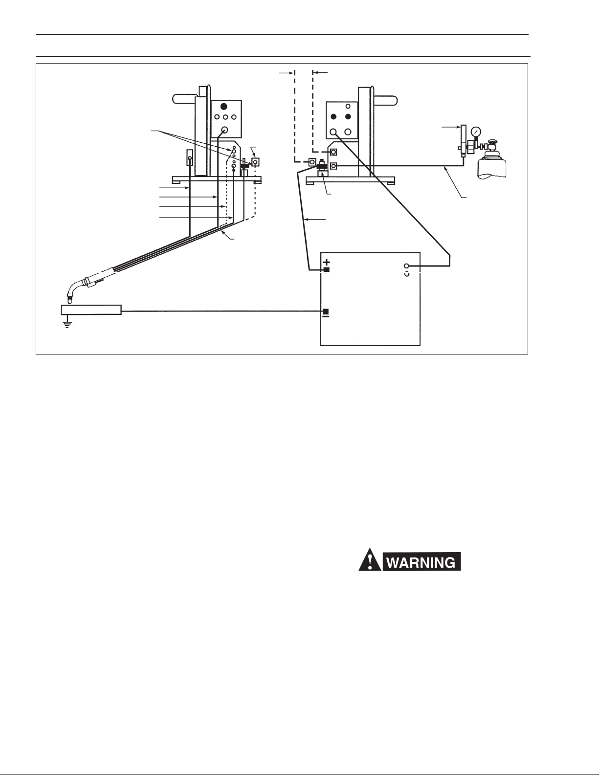
*WATER KIT -994466
TORCH CONDUIT
TORCH SWITCH
*TORCH WATER HOSE
TORCH GAS HOSE
WORK
GROUND
*WATER DRAIN HOSE - 40V76 (12-1/2 Ft.)
FRONT VIEW
*ADAPTOR
- 45V11
TORCH
POWER
CABLE
WELDING WORK CABLE
(4/O, Customer Supplied)
*WATER IN HOSE - 40V76 (12-1/2 Ft.)
REAR VIEW
REGULATOR/
FLOWMETER
POWER
CABLE
ADAPTOR - 634693
ELECTRODE WELDING
CABLE
(4/O, Customer Supplied)
C.P. POWER SOURCE
*Parts required when
using a Water Kit & Water
Cooled Torch.
Fig. 2 - Interconnection Diagram
IV. INSTALLATION
After checking to be sure you have all required components and accessories (see Section 11), proceed as
follows (with reference to Fig. 2, Interconnection Diagram):
A. HOSE AND ELECTRICAL CONNECTIONS
Connect shielding gas supply hose. Connect control cable to rear panel of unit and to power supply.
(If power supply is not new, check to make certain
that no wiring changes have been made which permit actuation of contactor by some means other
than power received through the welding control
cable receptacle. Any such modifications must be
removed before attaching control cable to power
supply.)
NOTE: When using a water-cooled torch, the water
connections shown in Figure 2 must also be
made.
B. TORCH CONNECTIONS
Attach torch gas hose to connection. Plug in torch
switch cable and lock by twisting. After inserting conduit liner (if used) and attaching wire outlet guide of
correct size, connect wire feed conduit to welding head
clamp and lock in place. Connect torch power cable to
power cable adaptor (with a second cable from that
stud to the power source).
C. INSTALLING FEED ROLL
1. Release the clapper on the accessory support assembly (Figure 6) by disengaging the retainer from
the clapper fork.
2. Remove thumbscrew, bell washer and flat washer
from the feed roll shaft.
3. Slip the feed roll on the shaft, engaging the key.
Be sure to observe the THIS SIDE OUT marking
on the feed roll.
4. Replace flat washer, bell washer and thumbscrew,
tightening screw sufficiently to eliminate all end play
from the feed roll.
D. INSTALLING SPOOL OF WIRE
Make sure safety glasses with side shields are worn
when handling or changing wire, or clipping wire
off at the spool or at the end of the torch-serious
eye injury can result due to the springiness of the
wire which quickly unravels, or a cut wire end which
may shoot across the room.
1. Remove hairpin clip from spindle.
2. Position the spool of wire so that when it is placed
on the spindle, wire will be drawn to the feed roll
from the bottom of the spool. The spool should be
held so that the index hole on the back will engage
the lug on the spindle.
10

SECTION 4 INSTALLATION
3. Slide the spool onto the spindle until it engages
the lug. Lock in place with the hairpin clip.
4. Loosen the brake screw in the center of the spindle
hub, then tighten it just enough to prevent coasting of the spool when wire is drawn from it. Too
much pressure will load the wire feed motor unnecessarily. Too little pressure will permit the spool
to overrun, causing the wire to kink and tangle.
5. Thread wire to torch as follows:
a. Round off the free end of the welding wire with
a file.
b. Raise the clapper to relieve pressure on the
feed roll.
c. Thread the wire through the inlet guide, over
the groove in the feed roll, and into the outlet
guide.
d. Replace the pressure roll clapper.
e. Remove nozzle and contact tip from torch. Inch
the wire until it emerges from the front end of
torch. Slide the contact tube over the end of
the wire and secure it in place. Replace torch
nozzle.
6. When wire coils are to be used instead of spools,
mount wire reel on spindle as though it were a spool
(see 1 and 3 above). Remove thumbnuts and cover
plate from reel. Remove coil from its package, but
do not remove its binding wires. Slide coil onto reel
so that wire will be drawn from bottom of coil (starting end for a coil is always the outer end). Replace
reel cover plate and thumbnuts. Cut off coil tie wires
and any kinked wire. Then adjust brake screw and
thread wire to torch as covered in 4 and 5 above.
E. ADJUSTING THE PRESSURE ROLL ASSEMBLY
When a new wire size or type is to be used, set the
pressure roll adjustment as follows:
1. Release the clapper and unscrew the pressure adjusting knob until the pressure spring is free.
2. Thread the wire through the inlet and outlet guides
of the accessory support.
3. Engage the clapper making sure the wire is held in
the feed roll groove.
4. Alternately press and release the torch switch (see
Caution note in Para. D above) while slowly tightening the pressure adjusting knob until the wire
begins to feed without slipping. The spring pressure applied should be the minimum required to
provide positive, nonslip wire feed. Too little pressure will result in wire slippage while excessive
pressure will scar and deform the wire. Note that a
light spring (1 82W55) is installed on the accessory support for use with soft and small diameter
hard wire. For large diameter hard wire, replace
this spring with a heavy spring (182W54) supplied
with the unit.
F. WATER KITS (Optional see Fig. 9)
Mount bulkhead adaptor (58V75) behind opening provided in vertical base plate, above gas connection, and
secure with screws (No. 8-32 x 3/8-in.) and lockwashers
provided. Attach coupling and adaptor (11N16) behind
bulkhead adaptor. Mount torch cable adaptor (45V11)
on welding power stud. Connect water drain hose to
this adaptor, and water inlet hose to adaptor 11N16.
Power source contactor becomes energized the
moment the torch trigger is depressed. Arcing can
occur if the wire is brought to a ground. Keep the
torch awayfrom ground until welding is to begin.
11

SECTION 5 OPERATIONS
V. ADJUSTMENTS AND OPERATION.
A. CONTROL SETTINGS
1. Turn the Main Power Switch on the rear control
panel to the ON position.
2. Set the dual Range wire speed switch to the High
or Low range desired. The Low range provides wire
speeds from 0-500 ipm, and the High range allows speeds from 400 through Maximum ipm.
3. Set the wire feed rate by adjusting the WIRE
SPEED control knob on the front panel. The wire
feed rate, in turn, controls the current furnished by
the CP power source.
IMPORTANT
If the factory-set acceleration time feature
does not satisfy your welding requirements, a
trim pot on the logic board can be adjusted to
provide the exact acceleration (time) characteristics you desire, as follows:
(1) If stumbling arc starts occur, the accel-
eration time may be too short and the trim
pot (R23) should be adjusted counterclockwise to increase the time.
(2) If burnbacks or near burnbacks occur, the
acceleration time may be too long and the
trim pot (R23) should be adjusted clockwise to decrease the time.
4. Set the ANTI-STICK control on the rear panel to
the desired setting depending on the amount of
burnback desired. The higher the setting, the
greater the amount of time that the contactor is
held in to allow the wire to burnback out of the
puddle, after releasing the torch switch.
B. FEEDING WIRE
If wire has been threaded through torch and contact tip
as directed in Sec. IV-D-5, simply operate the inch
switch or cut off wire, as required, so that the wire extends about 1/2 in. beyond the end of the torch nozzle.
C. SHIELDING GAS FLOW RATE
Hold gas purge pushbutton in and set desired gas
flow rate at the shielding gas regulator-flowmeter. Hold
push-button in at least 15 seconds to insure adequate
purging of gas hose and torch.
If preflow/postflow kit has been installed (inside the
control box) set its potentiometer for the desired preflow
and postflow intervals (range: 0. 1 to 3 seconds).
D. MAKING THE WELD
Start to weld by pressing the torch switch lever to actuate the torch switch. This closes the welding contactor,
and starts wire feed and gas flow. Then touch the end
of the welding wire to the workpiece to establish the
arc. The switch lever must be depressed for the duration of the weld. Welding action will be stopped and all
services discontinued when the lever is released and
returns to its original position. If the torch is withdrawn
from the workpiece during welding, the arc will be interrupted, but shielding gas flow and welding wire feed
will continue until the switch lever is released.
Do not allow metal-to-metal contact between the
wire feeder chassis and a metal surface connected
in any way to a welding ground. With such contact, a poor welding ground connection may create a difference in potential that sends part of the
welding current through the safety ground wiring
in the control cable and wire feeder, resulting in
burnout of that wiring and/or damage to wire feeder
circuitry. If the safety ground burns out, the operator may be exposed to 115V. shock hazard.
NOTE: If lock-in circuit (optional) has been installed,
switch lever can be released as soon as arc
has been struck. When weld is complete, services are discontinued by closing torch switch
again.
12

SECTION 6 OPERATIONS
VI. OPERATING SEQUENCE
NORMAL
1 . Close torch switch.
Gas solenoid opens, weld contactor closes,
wire feed motor runs.
2. Release torch switch.
Wire feed motor deenergized, brake circuit ef-
fective.
Anti-stick circuit energized.
3. Anti-stick circuit times out (delay determined
by setting of anti-stick potentiometer).
Weld contactor opens.
4. Release torch switch.
Gas solenoid valve closes.
PREFLOW/POSTFLOW
Same as NORMAL except that when torch switch is
closed, only gas solenoid valve is immediately energized. Contactor and wire feed motor are energized
only after interval established by setting of preflow potentiometer. When torch switch is opened, gas solenoid valve remains energized until interval established
by setting of postflow potentiometer has elapsed.
LOCK-IN
Same as NORMAL except that closing of torch switch
energizes a parallel switch in lock-in circuit, so torch
switch lever can be released immediately. At end of
weld, momentary closing of the torch switch initiates
the sequence that normally follows opening of that
switch.
NOTE: Lock-in and preflow1postflow may be used to-
gether after a capacitor is removed from the
lock-in printed circuit board. For installation, refer to the lock-in kit instruction literature (form
12-335).
13

SECTION 7 TROUBLESHOOTING
VII. TROUBLESHOOTING
Listed below are a number of trouble symptoms,
each followed by the checks or action suggested
to determine the cause. Listing of checks and/or
actions is inmost probable order, but is not necessarily 100% exhaustive. Always follow this general rule. Do not replace a printed circuit (PC) board
until you have made all the preceding checks. Always put the main power switch in OFFposition
before removing or installing a PC board. To avoid
damage, take great care not to grasp or pull on
components when removing a PC board. If a
printed circuit (PC) board is determined to be the
problem, check with your ESAB supplier for a
trade-in on a new PC board. Supply the distributor
with the part number of the PC board as well as
the serial number of the wire feeder Do not attempt
to repair the PC board yourself. Warranty on a PC
board will be null and void if repaired by customer
or an unauthorized repair shop.
A. SYMPTOM: Wire Feeder totally inoperative.
1. Check for 110-115 VAC between black and
white wires on main line switch (rear panel). If
not present, trouble lies in power input source.
2. If power is present at main line switch, check
for 110-115 VAC between P4-15 and P4-16. If
not present, reset circuit breaker.
B. SYMPTOM: Circuit breaker blows repeatedly as
soon as main line switch is turned ON.
1. Check wiring for short.
2. If no short can be found, replace J Governor
board.
C. SYMPTOM: Circuit breaker blows when torch
switch is closed.
1. Check for jammed or defective wire feed motor/drive unit.
2. If motor/drive unit is OK, replace logic board.
D. SYMPTOM: With torch switch closed, wire feed
motor runs, and weld contactor closes, but gas
solenoid is not energized.
1 . Check for missing (or loose) jumper between
TB1-5 and TB1-6.
2
. Check solenoid for defect.
3. Check for defective contact (NC) on gas
pushbutton switch.
E. SYMPTOM: With torch switch closed, weld
contactor closes and gas solenoid is energized,
but wire feed motor does not run.
1. Check for defect in cable to wire feed motor.
2. Check for excessively-worn motor brushes, or
other motor defect.
3. Check DC voltage across C7 on J Governor
board and turn WFS from min. to max. Volt-
age should adjust 0 to 10V. If voltage is there
but motor still does not run, replace J Governor board. If no voltage, replace J Governor or
logic board.
F. SYMPTOM: Wire feed motor does not run
when wire inch switch is activated.
1. Check switch for defect.
2. Check wiring beyond switch for break.
3. Replace J governor board.
4. Replace logic board.
G. SYMPTOM: No control over motor speed by
wire feed speed potentiometer.
1. Check wire speed potentiometer circuit across
P1 pins 9 and 10 with an ohmmeter. Resistance should range from 150 K to 50 K ohms
(max. to min.) in the High range, and from 110
K to 10 K ohms (max. to min.) in the Low range.
Replace potentiometer if defective.
2. Replace J governor board.
H. SYMPTOM: No control over anti-stick time.
1. Check anti-stick potentiometer with ohmmeter. Resistance should range from 0- 100 K
ohms. Replace potentiometer if defective.
2. Replace logic board.
I. SYMPTOM: Erratic or pulsing wire feed rate.
1. Replace J governor board.
J. SYMPTOM: Brake resistor (R2) burns out.
1. Replace resistor.
2. Replace logic board if R2 bums out again.
K. SYMPTOM: Motor runs as soon as main line
switch is closed.
1. If contactor and solenoid are also energized:
a. Check for defective torch switch or short
in switch cable.
b. Replace logic board.
2. If contactor and solenoid are not simultaneously energized:
a. Replace J governor board.
b. Replace logic board.
L. SYMPTOM: With torch switch closed, wire
feed motor runs, but welding contactor and
gas solenoid are not activated.
1. Check for break in wiring.
2. Check for blown fuse on logic board.
3. Replace logic board.
M. SYMPTOM: Ground Fault Light is ON and
torch trigger does not activate feeder.
1. Check or contact between the welding circuit
and the feeder chassis and clear any short
circuits.
2. Turn power OFF and back ON and
ground fault should reset.
3. Replace logic board.
4. Replace ground fault detector (sensor).
14

SECTION 8 MAINTENANCE
VIll. MAINTENANCE
If this equipment does not operate properly, stop
work immediately and investigate the cause of the
malfunction. Maintenance work must be performed
by an experienced person, and electrical work by
a trained electrician. Do not permit untrained persons to inspect, clean, or repair this equipment.
Use only recommended replacement parts.
A. GENERAL MAINTENANCE
Little maintenance is required to keep the wire feeder
in top operating condition. It is important, however, that
moving parts such as feed and pressure rolls, wire feed
motor, etc., be kept clean and free of dust or dirt. Cleaning is best accomplished by regularly blowing off these
parts with dry compressed air. This should be done
once for every eight hours of operating time, more often if necessary.
B. LUBRICATION OF MOTOR-GEAR UNIT
The EH-10A motor-gear unit is lubricated with a heavy
duty grease when assembled at the factory and should
not require further lubrication unless disassembled. If
disassembled, relubricate with Texaco Multifak grease.
C. CHECKING OR REPLACEMENT OF MOTOR
BRUSHES
Motor brushes should be checked periodically. If a
brush is broken, or worn down to less than 3/8-in.
length, it must be replaced. Brushes can be inspected
by unscrewing the brushholder plug and withdrawing
the brush assembly. Never remove a brush without
matchmarking it and its holder, so that it can be replaced in the same holder in its original position.
15

SECTION 9 REPLACEMENT PARTS
IX. REPLACEMENT PARTS DATA
1. All replacement parts are keyed on the illustrations which follow. Order replacement parts by part number and
part name, as shown on illustrations.
2. Many of the parts on the illustrations, particularly electronic parts, are vendor items. This means that they are
standard commercial parts made by and purchased from other manufacturers. If you order from these outside
sources, use the manufacturers part number or designation as shown in the Electrical Parts List.
3. Always state the series or serial number of the machine on which the parts are to be used. The serial number is
stamped on the unit nameplate.
ELECTRICAL PARTS LIST
Symbol Part No. Description and Vendor
ASP 92W64 Potentiometer 100K ohm, 2W - Allen Bradley No. J5054OD-J
WSP
C1 993716 Capacitor - I mfd. 600V
C2, C3 672348 Capacitor - .0 1 mfd. 1000V
GS 951125 Switch - Pushbutton - Switchcraft, No. 203 Littleswitch
GSV 2062305 Solenoid Valve - ASCO, P/N JS82611 0
IS 97W10 Switch - DPDT, Cutler Hammer 8906K1453
MLS, SWS 97W64 Switch - DPST 15A/125V, (Cutler Hammer No. 7560K5)
P3 182W64 Connector 2 POLE/2 Wire - Pass and Seymour No. 7468
P4 674569 Connector P/C - AMP Incorp. P/N 583617-3
P5 634772 Receptacle - Amphenol No. MS-3102A-18-12P
R2 17240003 Resistor - 3 Ohm, 25W, Ohmite Type 270-25. No. L25J3RO
TB-1 95W12 Terminal Block - Cinch - Jones No. 8-140
TB-2 92W11 Terminal Block - Jones No. 354-11-04-001
TR1 994303 Transformer, Prim. 117, 50-60 Cy. - Stancor No. P8362
SPINDLE ASSY.
948259 (See Fig. 8)
SPEED RANGE (H/LS)
SWITCH - 950629
(P3) RECEPTACLE - 182W64
EH-10A MOTOR-GEAR UNIT
ASSY. - 679773 (See Fig. 5)
ACCESSORY SUPPORT
(ASSY. - 49V51
See Fig. 6)
Not Illustrated
INSULATOR RING60N90
KEY - 28N33
THUMBSCREW61351087
FLAT WASHER - 64309431
BELL WASHER - 950783
n RECOMMENDED SPARE PARTS
GAS CONNECTION 58V58
(GSV) GAS SOLENOID
VALVE - 2062305n
INLET CONNECTION
74S76
POWER CABLE ADAPTOR BLOCK
ASSY. - 674156
WARNING DECAL - 954440*
CONTROL ASSY. - 37911
(See Fig. 4)
(WSP) - See Fig. 4
(GS) PUSHBUTTON PURGE SW. 951125
(IS) - INCH SWITCH - 97W10
WARNING DECAL - 995204
GROUND FAULT INDICATOR LAMP
(Ref.) OPENING FOR ESAB
POWER SOURCE LIFTING RING
BASE/FRAME
2075554
(2) SKID - 999629**
* Replace Decal if it Becomes Exces-
sively Worn or Lost
** Earlier wire feeder bases only con-
tained 2-skid mfg. holes. To install 3hole skids, use skid as a template and
redrill new holes in wire feeder base.
Fig. 3 - MIG-35 Wire Feeder, P/N 953552
16

SECTION 9 REPLACEMENT PARTS
WARNING LABEL 995164
(WSP)
KNOB 13730611
(R2) RESISTOR 17240003
WARNING LABEL
- 954440
SIDE PANEL - 37912YL
SWITCH, TOGGLE 97W64
SWITCH, TOGGLE 97W10
PC BOARD BRACKET - 37914
CHASSIS - 32305GY
FILTER
NETWORK
- 996918
POTENTIOMETER
- - 92W64
TERMINAL BLOCK
6 POS 20 AMP- 93W21
TERMINAL BLOCK 8 POS 15 AMP- 93W21
(WSP) POTENTIOMETER - 92W64
SWITCH, TOGGLE - 634518
PC BOARD ASSY.
LOGIC (P2) - 38178
COVER - 994309YL
WARNING LABEL
- 995204 (Electrical Shock)
PC BOARD ASSY. (P1)
J GOV. - 994236
SWITCH SEAL, BLACK
- 951474
CIRCUIT
BREAKER
- 2062161
STRAIN
RELIEF
- 96W85
KNOB - 951502
(P5) RECEPTACLE - 634722
Fig. 4 - Control Assembly, P/N 37911
8 - 32 UNC 2B
.25 DEEP - 2 PLCS
8 - 32 UNC 2B
.60 DEEP ON
ARMATURE SHAFT
(4) HEX, HD. SCREWS 5/16 - 18x3/4
(4) FLAT WASHER 5/16
(4) LOCKWASHER 5/16
5/16 - 18 UNC 2B
.63 MIN. DEPTH
(11 full threads)
VIEW A-A
Do not use old existing hardware to mount the motor. Only use the
5/16 hardware supplied.
.19 STRIP
LENGTH
Fig. 5 - EH-10A Motor-Gear Unit Assembly (40:1, 0-1000 ipm) P/N 679773
17

SECTION 9 REPLACEMENT PARTS
OUTPUT SHAFT ASSY.
(Part of 19734 OUTPUT GEAR CASE
OUTPUT GEAR CASE
19734 - (Includes
Output Shaft Assy.
Shown Above)
FEED ROLL LOCATING
COLLAR -599877
GEAR ASSY. B - 20293
OUTPUT SHAFT SEALl
GEAR ASSY. A - 20292
MAGNET ASSY. - 19730
ARMATURE SHAFT SEALl
OUTPUT GEAR CASE GASKET*
llBRUSH END BELL - 19732
(Includes TWO-BRUSH
HOLDER ASSYS.)
ARMATURE & BEARINGS 19726
Includes:
ARMATURE BEARING - 20288
MOTOR CORD LEAD - 19731
BRUSH HOLDERll
BRUSH
CAP
(2) CARBON BRUSH
REPLACEMENT KIT - 679784
Includes:
(2) BRUSH CAP
(2) CARBON BRUSH
SCREW 10-24 X 1/2
Fig. 5A - EH-10A Motor-Gear Unit Parts Breakdown
CLAPPER - 60N98
ROLL PIN 1/4 x 1-3/4 LG
INLET
INLET WIRE GUIDE
29N13
INLET GUIDE INSERT
05N58
SETSCREW #6-32 x 1/4 LG
(2) LOCKING HANDLE
BOLT 1/4 x 1-5/8 LG
SUPPLIED
HEAVY SPRING - 182W54 (FOR LARGE DIA. HARD WIRE)
(61330849)
ASSEM. - 49V44
(Includes)
SPACER - 60N79
PRESSURE ROLL
28V52
NUT - 5/16-18
SHAFT - 60N65
KNOB - 60N68
LIGHT SPRING - 182W55 (FOR SOFT &
SMALL DIA. HARD WIRE)
RETAINER - 58N24
FORK - 49V43
WIRE OUTLET GUIDE/INSERT*
(SEE TABLE 1)
CONDUIT
OUTLET
WIRE OUTLET*
GUIDE
CLAMP - 61N02
ROLLPIN - 3/16 x 1-3/4 LG
SCREW - 5/16 - 18 x 2 LG
* Outlet Guide Not Included in Assembly Part No.
49V51.
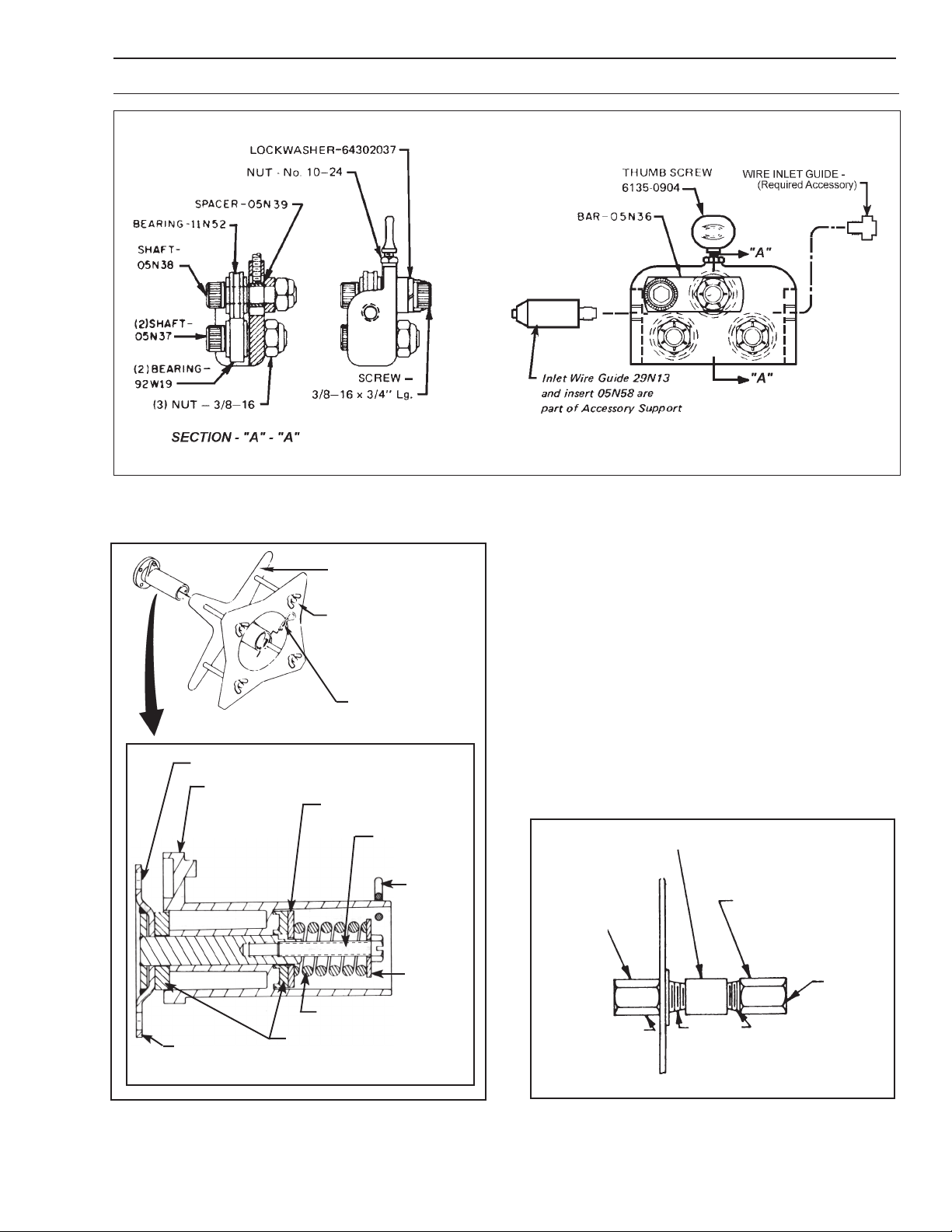
Fig. 6 - Accessory Support Assembly, P/N 49V51 - 2 Roll Drive
(4 Roll Drive - See Supplement F-12-821)
18
SECTION 9 REPLACEMENT PARTS
11N53
Fig. 7 - Optional Wire Straightener, P/N 34V74
WIRE REEL - 995570
Includes:
REEL - 995568
COVER - 995569
(4) WING NUT, 1/213
63398183
REEL
(4) .359 DIA. HOLE ON 3 DIA. D.C.
SPINDLE - 948258
SUPPORT 948257
(2) BRAKE PAD - 948255
(Ref. Hair Pin Clip)
D TYPE WASHER 948254
SPRING - 948253
SCREW
5/1618 x 2
HAIR PIN
CLIP
634347
WASHER 948256
WATER
CONNECTION
58V75
(OUTLET)
5/8 - LH
COUPLING - 68121075
ADAPTOR - 11N16
(INLET)
5/8 - 18LH
1/4N.P.T.
Fig. 8 - Spindle Assembly, P/N 948259,
Optional Wire Reel, P/N 995570
Fig. 9 - Water Kit, 994466
19

Fig. 11 - Schematic Diagram
20

Fig. 12 - Wiring Diagram
21

NOTES
22

DESIGN CHANGES
The E edition of this booklet include the following:
1. Changed control fuse (F1) from 5 to 6-1/4 amps.
2. Changed logic board from 994239 to 675473.
3. Changed mother board from 994281 to 675475.
4. Add information on page 16 regarding interchangeability of logic/mother boards.
The F edition of this booklet includes the following:
1. Corrected J Gov. p.c. P/N from 999741 to 994236.
2. Corrected Spotweld Kit P/N from 994396 to 999741.
3. Added information to Table 1.
4. Added note regarding bypassing WSV if installed when water recirculator is used.
The G edition of this booklet includes the following: 1. Added parts breakdown for EH- 10A motor.
2. Added optional Dual Range Wire Speed Kit & related information.
The H edition includes the following for serial numbered units beginning with M89P - - - - - (for P/N
953552) and M89N - - - - - (for P/N 677634):
1. Added wire speed Range (Hi-Low) Switch to front panel.
2. Revised front panel component locations.
3. Changed resistor R2 from 50W, 5 ohm to 25W, 3 ohm.
4. Changed fuse (F1, 6-1/4 amps.) to circuit breaker (CB, 7 amps.)
The J edition covers part number change of Gas Purge switch (GS) 994925 to 951125.
The K edition covers change in control cables for connecting wire feeder to latest power sources and to delete the
discontinued water kit with solenoid valve (2075760) and wire wiper accessories.
The L edition covers changes in controls, optional accessories, operating sequences and troubleshooting.
The L edition was edited to change the part number for the Control Assembly from 953549 which was incorrect to
37911. The date was updated, but there was not a revision change.
The M edition updates Table 1, removes information on the Wire Wiper Holder which is no longer used and
updates call outs and/or part numbers on Fig. 3, Fig. 4, Fig. 5A, Fig. 6 and Fig. 7.
23

ESAB Welding & Cutting Products, Florence, SC Welding Equipment
COMMUNICATION GUIDE - CUSTOMER SERVICES
A. CUSTOMER SERVICE QUESTIONS:
Order Entry Product Availability Pricing Delivery
Order Changes Saleable Goods Returns Shipping Information
Telephone: (800)362-7080 / Fax: (800) 634-7548
Telephone: (800)783-5360 / Fax: (800) 783-5362
Telephone: (800) 235-4012/ Fax: (888) 586-4670
B. ENGINEERING SERVICE: Telephone: (843) 664-4416 / Fax : (800) 446-5693
Welding Equipment Troubleshooting Hours: 7:30 AM to 5:00 PM EST
Warranty Returns Authorized Repair Stations
C. TECHNICAL SERVICE: Telephone: (800) ESAB-123/ Fax: (843) 664-4452
Part Numbers Technical Applications Hours: 8:00 AM to 5:00 PM EST
Performance Features Technical Specifications Equipment Recommendations
D. LITERATURE REQUESTS: Telephone: (843) 664-5562 / Fax: (843) 664-5548
E. WELDING EQUIPMENT REPAIRS: Telephone: (843) 664-4487 / Fax: (843) 664-5557
Repair Estimates Repair Status Hours: 7:30 AM to 3:30 PM EST
F. WELDING EQUIPMENT TRAINING:
Telephone: (843)664-4428 / Fax: (843) 679-5864
Training School Information and Registrations Hours: 7:30 AM to 4:00 PM EST
G. WELDING PROCESS ASSISTANCE:
Telephone: (800) ESAB-123 / Fax: (843) 664-4454 Hours: 7:30 AM to 4:00 PM EST
H. TECHNICAL ASST. CONSUMABLES:
Telephone : (800) 933-7070 Hours: 7:30 AM to 5:00 PM EST
Eastern Distribution Center
Central Distribution Center
Western Distribution Center
Hours: 7:30 AM to 4:00 PM EST
IF YOU DO NOT KNOW WHOM TO CALL
Telephone: (800) ESAB-123/ Fax: (843) 664-4452/ Web:http://www.esab.com
F-12-786-M 3/2001 Printed in U.S.A.
Hours: 7:30 AM to 5:00 PM EST
 Loading...