


INSTRUCTION MANUAL
WIRE FEEDER
EFFECTIVE WITH SERIAL NUMBER WK-I930001
F15-143-C
October, 2008
Mig 2E
This manual provides complete instructions on the Mig 2E Wire Feeder, P/N 34157.
These INSTRUCTIONS are for experienced operators. If you are not fully familiar with the principles of operation
and safe practices for arc welding equipment, we urge you to read our booklet, "Precautions and Safe Practices
for Arc Welding, Cutting, and Gouging", Form 52-529. Do NOT permit untrained persons to install, operate, or
maintain this equipment. Do NOT attempt to install or operate this equipment until you have read and fully
understand these instructions. If you do not fully understand these instructions, contact your supplier for
further information. Be sure to read the Safety Precautions (Section I) before installing or operating this
equipment.
Be sure this information reaches the operator.
You can get extra copies through your supplier.

USER RESPONSIBILITY
This equipment will perform in conformity with the description thereof contained in this manual and accompanying
labels and/or inserts when installed, operated, maintained and repaired in accordance with the instructions provided.
This equipment must be checked periodically. Malfunctioning equipment should not be used. Parts that are broken,
missing, worn, distorted or contaminated should be replaced immediately. Should such repair or replacement become
necessary, the manufacturer recommends that a telephone or written request for service advice be made to the
Authorized Distributor from whom it was purchased.
This equipment or any of its parts should not be altered without the prior written approval of the manufacturer. The
user of this equipment shall have the sole responsibility for any malfunction which results from improper use, faulty
maintenance, damage, improper repair or alteration by anyone other than the manufacturer or a service facility
designated by the manufacturer.
TABLE OF CONTENTS
SECTION TITLE PAGE
PARAGRAPH
1 SAFETY ................................................................................................................................3
2 DESCRIPTION AND SPECIFICATION ...................................................................................7
2.1 Mig 2E Wire Feeder ................................................................................................7
2.2 Mig 2E Wire Feeder Option .....................................................................................7
3 EQUIPMENT ...........................................................................................................................9
3.1 General ...................................................................................................................9
3.2 Companion Equipment and Accessories.................................................................9
3.3 Accessories.............................................................................................................9
4 INSTALLATION .....................................................................................................................10
4.1 Installation .............................................................................................................10
5 OPERATION .........................................................................................................................11
5.1 Adjustments and Operation...................................................................................11
5.2 Operating Sequence .............................................................................................11
6 SERVICE ..............................................................................................................................12
6.1 Maintenance .........................................................................................................12
7 REPLACEMENT PARTS.......................................................................................................15
7.1 General .................................................................................................................15
i
2

SAFETY PRECAUTIONS
WARNING: These Safety Precautions are for
your protection. They summarize precautionary information from the references listed in
Additional Safety Information section. Before
performing any installation or operating procedures, be
sure to read and follow the safety precautions listed below
as well as all other manuals, material safety data sheets,
labels, etc. Failure to observe Safety Precautions can result
in injury or death.
PROTECT YOURSELF AND OTHERS
Some welding, cutting, and gouging
processes are noisy and require ear
protection. The arc, like the sun, emits
ultraviolet (UV) and other radiation and
can injure skin and eyes. Hot metal can cause burns.
Training in the proper use of the processes and equipment is essential to prevent accidents. Therefore:
1. Always wear safety glasses with side shields in any work
area, even if welding helmets, face shields, and goggles
are also required.
2. Use a face shield fitted with the correct filter and cover
plates to protect your eyes, face, neck, and ears from
sparks and rays of the arc when operating or observing
operations. Warn bystanders not to watch the arc and
not to expose themselves to the rays of the electric-arc
or hot metal.
3. Wear flameproof gauntlet type gloves, heavy long-sleeve
shirt, cuffless trousers, high-topped shoes, and a welding helmet or cap for hair protection, to protect against
arc rays and hot sparks or hot metal. A flameproof apron
may also be desirable as protection against radiated
heat and sparks.
4. Hot sparks or metal can lodge in rolled up sleeves,
trouser cuffs, or pockets. Sleeves and collars should be
kept buttoned, and open pockets eliminated from the
front of clothing
5. Protect other personnel from arc rays and hot sparks
with a suitable non-flammable partition or curtains.
6. Use goggles over safety glasses when chipping slag or
grinding. Chipped slag may be hot and can fly far.
Bystanders should also wear goggles over safety glasses.
FIRES AND EXPLOSIONS -- Heat from
flames and arcs can start fires. Hot slag
or sparks can also cause fires and explosions. Therefore:
1. Remove all combustible materials well away from the
work area or cover the materials with a protective nonflammable covering. Combustible materials include wood,
cloth, sawdust, liquid and gas fuels, solvents, paints and
coatings, paper, etc.
2. Hot sparks or hot metal can fall through cracks or
crevices in floors or wall openings and cause a hidden
smoldering fire or fires on the floor below. Make certain
that such openings are protected from hot sparks and
metal.“
3. Do not weld, cut or perform other hot work until the
workpiece has been completely cleaned so that there
are no substances on the workpiece which might produce flammable or toxic vapors. Do not do hot work on
closed containers. They may explode.
4. Have fire extinguishing equipment handy for instant use,
such as a garden hose, water pail, sand bucket, or
portable fire extinguisher. Be sure you are trained in its
use.
5. Do not use equipment beyond its ratings. For example,
overloaded welding cable can overheat and create a fire
hazard.
6. After completing operations, inspect the work area to
make certain there are no hot sparks or hot metal which
could cause a later fire. Use fire watchers when necessary.
7. For additional information, refer to NFPA Standard 51B,
"Fire Prevention in Use of Cutting and Welding Pro-
--
cesses", available from the National Fire Protection Association, Batterymarch Park, Quincy, MA 02269.
ELECTRICAL SHOCK -- Contact with live
electrical parts and ground can cause
severe injury or death. DO NOT use AC
welding current in damp areas, if movement is confined, or if there is danger of
falling.
1. Be sure the power source frame (chassis) is connected
to the ground system of the input power.
2. Connect the workpiece to a good electrical ground.
3. Connect the work cable to the workpiece. A poor or
missing connection can expose you or others to a fatal
shock.
4. Use well-maintained equipment. Replace worn or damaged cables.
5. Keep everything dry, including clothing, work area,
cables, torch/electrode holder, and power source.
6. Make sure that all parts of your body are insulated from
work and from ground.
7. Do not stand directly on metal or the earth while working
in tight quarters or a damp area; stand on dry boards or
an insulating platform and wear rubber-soled shoes.
8. Put on dry, hole-free gloves before turning on the power.
9. Turn off the power before removing your gloves.
10. Refer to ANSI/ASC Standard Z49.1 (listed on next page)
for specific grounding recommendations. Do not mistake the work lead for a ground cable.
ELECTRIC AND MAGNETIC FIELDS —
May be dangerous. Electric current flowing through any conductor causes localized Electric and Magnetic Fields
(EMF). Welding and cutting current creates EMF around welding cables and
welding machines. Therefore:
1. Welders having pacemakers should consult their physician before welding. EMF may interfere with some pacemakers.
2. Exposure to EMF may have other health effects which are
unknown.
3. Welders should use the following procedures to minimize
exposure to EMF:
A. Route the electrode and work cables together. Secure
them with tape when possible.
B. Never coil the torch or work cable around your body.
C. Do not place your body between the torch and work
cables. Route cables on the same side of your body.
D. Connect the work cable to the workpiece as close as
possible to the area being welded.
E. Keep welding power source and cables as far away
from your body as possible.
3
10/98

FUMES AND GASES -- Fumes and
gases, can cause discomfort or harm,
particularly in confined spaces. Do
not breathe fumes and gases. Shielding gases can cause asphyxiation.
Therefore:
1. Always provide adequate ventilation in the work area by
natural or mechanical means. Do not weld, cut, or gouge
on materials such as galvanized steel, stainless steel,
copper, zinc, lead, beryllium, or cadmium unless positive mechanical ventilation is provided. Do not breathe
fumes from these materials.
2. Do not operate near degreasing and spraying operations. The heat or arc rays can react with chlorinated
hydrocarbon vapors to form phosgene, a highly toxic
gas, and other irritant gases.
3. If you develop momentary eye, nose, or throat irritation
while operating, this is an indication that ventilation is not
adequate. Stop work and take necessary steps to improve ventilation in the work area. Do not continue to
operate if physical discomfort persists.
4. Refer to ANSI/ASC Standard Z49.1 (see listing below)
for specific ventilation recommendations.
5. WARNING: This product, when used for welding or
cutting, produces fumes or gases which
contain chemicals known to the State of
California to cause birth defects and, in
some cases, cancer. (California Health &
Safety Code §25249.5 et seq.)
CYLINDER HANDLING -- Cylinders, if
mishandled, can rupture and violently
release gas. Sudden rupture of cylinder, valve, or relief device can injure or
kill. Therefore:
1. Use the proper gas for the process and use the proper
pressure reducing regulator designed to operate from
the compressed gas cylinder. Do not use adaptors.
Maintain hoses and fittings in good condition. Follow
manufacturer's operating instructions for mounting regulator to a compressed gas cylinder.
2. Always secure cylinders in an upright position by chain
or strap to suitable hand trucks, undercarriages, benches,
walls, post, or racks. Never secure cylinders to work
tables or fixtures where they may become part of an
electrical circuit.
3. When not in use, keep cylinder valves closed. Have
valve protection cap in place if regulator is not connected. Secure and move cylinders by using suitable
hand trucks. Avoid rough handling of cylinders.
4. Locate cylinders away from heat, sparks, and flames.
Never strike an arc on a cylinder.
5. For additional information, refer to CGA Standard P-1,
"Precautions for Safe Handling of Compressed Gases in
Cylinders", which is available from Compressed Gas
Association, 1235 Jefferson Davis Highway, Arlington,
VA 22202.
EQUIPMENT MAINTENANCE -- Faulty or
improperly maintained equipment can
cause injury or death. Therefore:
1. Always have qualified personnel perform the installation, troubleshooting, and maintenance work. Do not
perform any electrical work unless you are qualified to
perform such work.
2. Before performing any maintenance work inside a power
source, disconnect the power source from the incoming
electrical power.
3. Maintain cables, grounding wire, connections, power
cord, and power supply in safe working order. Do not
operate any equipment in faulty condition.
4. Do not abuse any equipment or accessories. Keep
equipment away from heat sources such as furnaces,
wet conditions such as water puddles, oil or grease,
corrosive atmospheres and inclement weather.
5. Keep all safety devices and cabinet covers in position
and in good repair.
6. Use equipment only for its intended purpose. Do not
modify it in any manner.
ADDITIONAL SAFETY INFORMATION -- For
more information on safe practices for electric arc welding and cutting equipment, ask
your supplier for a copy of "Precautions and
Safe Practices for Arc Welding, Cutting and
Gouging", Form 52-529.
The following publications, which are available from the
American Welding Society, 550 N.W. LeJuene Road, Miami, FL 33126, are recommended to you:
1. ANSI/ASC Z49.1 - "Safety in Welding and Cutting"
2. AWS C5.1 - "Recommended Practices for Plasma Arc
Welding"
3. AWS C5.2 - "Recommended Practices for Plasma Arc
Cutting"
4. AWS C5.3 - "Recommended Practices for Air Carbon
Arc Gouging and Cutting"
5. AWS C5.5 - "Recommended Practices for Gas Tungsten
Arc Welding“
6. AWS C5.6 - "Recommended Practices for Gas Metal Arc
Welding"“
7. AWS SP - "Safe Practices" - Reprint, Welding Handbook.
8. ANSI/AWS F4.1, "Recommended Safe Practices for
Welding and Cutting of Containers That Have Held
Hazardous Substances."
MEANING OF SYMBOLS - As used throughout this manual: Means Attention! Be Alert!
Your safety is involved.
Means immediate hazards which, if
not avoided, will result in immediate,
serious personal injury or loss of life.
Means potential hazards which could
result in personal injury or loss of life.
Means hazards which could result in
minor personal injury.
SP98-10
4

PRÉCAUTIONS DE SÉCURITÉ
AVERTISSEMENT: Ces règles de sécurité ont pour objet
d’ assurer votre protection. Veillez à lire et à observer les
précautions énoncées ci-dessous avant de monter l’
équipement ou de commercer à l’utiliser. Tout défaut
d’observation de ces précautions risque d’entraîner des
blessures graves ou mortelles.
1. PROTECTION INDIVIDUELLE-- Les brûlures de la
peau et des yeux dues au rayonnement de l’arc
électrique ou du métal incandescent, lors du soudage
au plasma ou à l’électrode ou lors du gougeage à
l’arc, peuvent s’avérer plus graves que celles
résultant d’une exposition prolongée au soleil. Aussi
convient-il d’observer les précautions suivantes:
a. Portez un écran facial adéquat muni des plaques
protectrices et des verres filtrants appropriés afin de
vous protéger les yeux, le visage, le cou et les oreilles
des étincelles et du rayonnement de l’arc électrique
lorsque vous effectuez des soudures ou des coupes
ou lorsque vous en observez l’exécution.
AVERTISSEZ les personnes se trouvant à proximité
de façon à ce qu’elles ne regardent pas l’arc et à ce
qu’elles ne s’exposent pas à son rayonnement, ni à
celui du métal incandescent.
b. Portez des gants ignifugés à crispins, une tunique
épaisse à manches longues, des pantalons sans
rebord, des chaussures à embout d’acier et un
casque de soudage ou une calotte de protection, afin
d’éviter d’exposer la peau au rayonnement de l’arc
électrique ou du métal incandescent. ll est également
souhaitable d’utiliser un tablier ininflammable de
façon à se protéger des étincelles et du rayonnement
thermique.
c. Les étincelles ou les projections de métal incandes-
cent risquent de se loger dans des manches
retroussées, des bords relevés de pantalons ou dans
des poches. Aussi convient-il de garder boutonnés le
col et les manches et de porter des vêtements sans
poches à l’avant.
d. Protégez des étincelles et du rayonnement de l’arc
électrique les autres personnes travaillant à proximité
à l’aide d’un écran ininflammable adéquat.
e. Ne jamais omettre de porter des lunettes de sécurité
lorsque vous vous trouvez dans un secteur où l’on
effectue des opérations de soudage ou de coupage à
l’arc. Utilisez des lunettes de sécurité à écrans ou
verres latéraux pour piquer ou meûler le laitier. Les
piquetures incandescentes de laitier peuvent être
projetées à des distances considérables. Les
personnes se trouvant à proximité doivent également
porter des lunettes de protection.
f. Le gougeage à l’arc et le soudage à l’arc au plasma
produisent un niveau de bruit extrêmement élevé (de
100 à 114 dB) et exigent par conséquent l’emploi de
dispositifs appropriés de protection auditive.
2. PRÉVENTION DES INCENDES-- Les projections de
laitier incandescent ou d’étincelles peuvent
provoquer de graves incendies au contact de
matériaux combustibles solides, liquides ou gazeux.
Aussi faut-il observer les précautions suivantes:
a. Éloigner suffisamment tous les matériaux combus-
tibles du secteur où l’on exécute des soudures ou des
coupes à l’arc, à moins de les recouvrir complètement
d’une bâche non-inflammable. Ce type de matériaux
comprend notamment le bois, les vêtements, la sciure,
l’essence, le kérosène, les peintures, les solvants, le
gaz naturel, l’acétylène, le propane et autres substances combustibles semblables.
b. Les étincelles ou les projections de métal incandes-
cent peuvent tomber dans des fissures du plancher ou
dans des ouvertures des murs et y déclencher une
ignition lente cachée. Veiller à protéger ces ouvertures
des étincelles et des projections de métal.
c. N’exécutez pas de soudures, de coupes, d’opérations
de gougeage ou autres travaux à chaud à la surface
de barils, bidons, réservoirs ou autres contenants
usagés, avant de les avoir nettoyés de toute trace de
substance susceptible de produire des vapeurs
inflammables ou toxiques.
d. En vue d’assurer la prévention des incendies, il
convient de disposer d’un matériel d’extinction prêt à
servir immédiatement, tel qu’un tuyau d’arrosage, un
seau à eau, un seau de sable ou un extincteur portatif.
e. Une fois le travail à l’arc terminé, inspectez le secteur
de façon à vous assurer qu’aucune étincelle ou projection de métal incandescent ne risque de provoquer
ultérieurement un feu.
3. CHOC ÉLECTRIQUE-- Le gougeage à l’arc et à l’arc
au plasma exige l’emploi de tensions à vide
relativement importantes; or, celles-ci risquent de
causer des dommages corporels graves et même
mortels en cas d’utilisation inadéquate. La gravité du
choc électrique reçu dépend du chemin suivi par le
courant à travers le corps humain et de son intensité.
a. Ne laissez jamais de surfaces métalliques sous ten-
sion venir au contact direct de la peau ou de
vêtements humides. Veillez à porter des gants bien
secs.
b. Si vous devez effectuer un travail sur une surface
métallique ou dans un secteur humide, veillez à assurer votre isolation corporelle en portant des gants secs
et des chaussures à semelles de caoutchouc et en
vous tenant sur une planche ou une plate-forme
sèche.
c. Mettez toujours à la terre le poste de soudage/coupage
en le reliant par un câble à une bonne prise de terre.
d. N’utilisez jamais de câbles usés ou endommagés. Ne
surchargez jamais le câble. Utilisez toujours un
équipement correctement entretenu.
e. Mettez l’équipement hors tension lorsqu’il n’est pas en
service. une mise à la masse accidentelle peut en
effet provoquer une surchauffe de l’équipement et un
danger d’incendie. Ne pas enrouler ou passer le câble
autour d’une partie quelconque du corps.
f. Vérifiez si le câble de masse est bien relié à la pièce en
un point aussi proche que possible de la zone de
travail. Le branchement des câbles de masse à
l’ossature du bâtiment ou en un point éloigné de la
zone de travail augmente en effet le risque de passage d’un courant de sortie par des chaînes delevage
5
9/97

des câbles de grue ou divers chemins électriques.
g. Empêchez l’apparition de toute humidité, notamment
sur vos vêtements, à la surface de l’emplacement de
travail, des câbles, du porte-électrode et du poste de
soudage/coupage. Réparez immédiatement toute
fuite d’eau.
4. VENTILATION-- La respiration prolongée des fumées
résultant des opérations de soudage/coupage, à
l’intérieur, d’un local clos, peut provoquer des malaises et des dommages corporels. Aussi convient-il
d’observer les précautions suivantes:
a. Assurez en permanence une aération adéquate de
l’emplacement de travail en maintenant une ventilation naturelle ou à l’aide de moyens mécaniques.
N’effectuez jamais de travaux de soudage ou de
coupage sur des matériaux de zinc, de plomb, de
beryllium ou de cadmium en l’absence de moyens
mécaniques de ventilation capables d’empêcher
l’inhalation des fumées dégagées par ces matériaux.
b. N’effectuez jamais de travaux de soudage ou de
coupage à proximité de vapeurs d’hydrocarbure
chloré résultant d’opérations voisines de dégraissage
ou de pulvérisation. La chaleur dégagée ou le
rayonnement de l’arc peut déclencher la formation de
phosgène -- gaz particulièrement toxique -- et d’autres
gaz irritants, à partir des vapeurs de solvant.
c. Une irritation momentanée des yeux, du nez ou de la
gorge constatée au cours de l’utilisation de
l’équipement dénote un défaut de ventilation. Arrêtezvous de travailler afin de prendre les mesures nécessaires à l’amélioration de la ventilation. Ne poursuivez
pas l’opération entreprise si le malaise persiste.
d. Certaines commandes comportent des canalisations
où circule de l’hydrogène. L’armoire de commande est
munie d’un ventilateur destiné à empêcher la formation de poches d’hydrogène, lesquelles présentent un
danger d’explosion; ce ventilateur ne fonctionne que
si l’interrupteur correspondant du panneau avant se
trouve placé en position ON (Marche). Veillez à
manœuvrer cette commande en vérifiant si le
couvercle est bien en place, de façon à assurer
l’efficacité de la ventilation ainsi réalisée. Ne jamais
débrancher le ventilateur.
e. Les fumées produites par l’opération de soudage ou
de coupage peuvent s’avérer toxiques. Aussi est-il
nécessaire de disposer en permanence d’un dispositif
adéquat de ventilation de type aspirant, afin d’éliminer du voisinage de l’opérateur tout dégagement de
fumée visible.
f. Consultez les recommandations particulières en
matière de ventilation indiquées à l’alinéa 6 de la
norme Z49.1 de l’AWS.
5. ENTRETIEN DE L’ÉQUIPEMENT-- Un équipement
entretenu de façon défectueuse ou inadéquate risque
non seulement de réaliser un travail de mauvaise
qualité mais, chose plus grave encore, d’entraîner
des dommages corporels graves, voire mortels en
déclenchant des incendies ou des chocs électriques.
Observez par conséquent les précautions suivantes:
a. Efforcez-vous de toujours confier à un personnel qua-
lifié l’installation, le dépannage et l’entretien du poste
de soudage et de coupage. N’effectuez aucune
réparation électrique sur l’équipement à moins d’être
qua-lifié à cet effet.
b. Ne procédez jamais à une tâche d’entretien
quelconque à l’intérieur du poste de soudage/
coupage, avant d’avoir débranché l’alimentation
électrique.
c. Maintenez en bon état de fonctionnement les câbles,
le câble de masse, les branchements, le cordon
d’alimentation et le poste de soudage/coupage.
N’utilisez jamais le poste ou l’équipement s’il présente
une défectuosité quelconque.
d. Prenez soin du poste de soudage et de coupage et
des équipements accessoires. Gardez-les à l’écart
des sources de charleur, notamment des fours, de
l’humidité, des flaques d’eau maintenez-les à l’abri des
traces d’huile ou de graisse, des atmosphères corrosives et des intempéries.
e. Laissez en place tous les dispositifs de sécurité et tous
les panneaux de l’armoire de commande en veillant à
les garder en bon état.
f. Utilisez le poste de soudage/coupage conformément à
son usage prévu et n’effectuez aucune modification.
6. INFORMATIONS COMPLÉMENTAIRES RELATIVES
À LA SÉCURITÉ--
Pour obtenir des informations complémentaires sur les
règles de sécurité à observer pour le montage et
l’utilisation d’équipements de soudage et de coupage
électriques et sur les méthodes de travail
recommandées, demandez un exemplaire du livret N°
52529 “Precautions and Safe Practices for Arc Welding, Cutting and Gouging” publié par ESAB. Nous
conseillons également de consulter les publications
sui-vantes, tenues à votre disposition par l’American
Welding Society, 550 N.W. LeJuene Road, Miami, FL
32126:
a. “Safety in Welding and Cutting” AWS Z49.1
b. “Recommended Safe Practices for Gas-Shielded Arc
Welding “AWS A6. 1.
c. “Safe Practices for Welding and Cutting Containers
That Have Held Combustibles” AWS-A6.0.
d. “Recommended Safe Practices for Plasma Arc Cut-
ting” AWS-A6. 3.
e. “Recommended Safe Practices for Plasma Arc Weld-
ing” AWS-C5. 1.
f. “Recommended Safe Practices for Air Carbon Arc
Gouging and Cutting” AWS-C5. 3.
g. “Code For Safety in Welding and Cutting”
CSA-Standard W117. 2.
9/97
6

SECTION 2
DESCRIPTION AND SPECIFICATION
2.1 Mig 2E Wire Feeder
The Mig 2E Wire Feeder (Figure 2-1 and Table 2-1)
described in this manual is designed for short arc,
spray arc mig or cored wire welding with a constant
potential (CP) welding power source.
Secondary input from the Power Source can be DC
"+" or DC "-" depending on the requirements of the
wire type being used.
Mig spot welding can be done with the Mig 2E if it is
equipped with optional spot-welding features. Addition of spot-welding circuitry in no way modifies
capability of the unit for normal mig, or cored wire
welding.
The Mig 2E uses a PM wire drive motor designed to
feed wires from .023 to 5/64-inches in diameter. Rate
of wire feed (50-650 inches per minute) is precisely
controlled by a solid-state, Pulse Width Modulated
(PWM) governor printed circuit board housed in the
control assembly. For operator safety, the torch switch
is energized by 12 volts ac supplied by the control. All
interconnecting cables and hoses are quickly detachable to provide maximum portability of the wire
feeder.
The Mig 2E wire feeder is designed to set on flat surfaces
or mount on a swivel post, if desired, allowing movement
as necessary during torch operations. The standard
features of the Mig 2E wire feeder follows:
• 2-roll geared drive stand
• One drive roll and one pressure roll
• Internal gas solenoid
• Ten-foot (3m) control cable w/19-pin amphenol style
plug (factory installed)
• Ten-foot (3m) gas hose w/fittings (factory installed)
• "Euro" style torch connection
• "ON" indicator light
• Wire feed speed potentiometer
2.2 Mig 2E Wire Feeder Option. The following
option is available from ESAB or your supplier.
• Spot/Burnback/Pre-postflow/Trigger Lock Mod-
ule (P/N 34182). Easy to install kit permits the
operator to set times for spot welding (0-5 sec), wire
burnback (0-0.6 sec), gas preflow (0-5 sec) and gas
postflow (0-7.5 sec). This module also includes
trigger lock which allows the welder to make long
welds without continuously depressing the torch trigger. Includes module and current detector.
Table 2-1. Mig 2E Specifications
Input Power Required ....................................................... 42 V ac, 5A, 50/60 Hz, 1-phase
Wire Feed Speed Range ................................................ 50-650 in./min. (1.3-16.5 m/min.)
Wire Sizes Accommodated:
Hard/Soft............................................................ .023 thru 1/16 in. (0.6 thru 1.6 mm)
Flux Cored ......................................................... .035 thru 5/64-in. (0.9 thru 2.0 mm)
Length ........................................................................................................... 21 in. (54 cm)
Width9 in. (23 cm)
Height* ....................................................................................................... 9.25 in. (24 cm)
Weight (approx**)....................................................................................... 28 lbs (12.7 kg)
*Add 2-3/4-in. (7 cm) for spindle and spindle arm.
**8-ft (2.4m) control cable and hose included in specified weight.
7

SECTION 2
POWER "ON"
INDICATOR
DESCRIPTION AND SPECIFICATION
REEL STAND
WIRE SPOOL HUB
WIRE FEED
SPEED CONTROL
REEL STAND
WELDING POWER
INPUT STAND
MIG TORCH
CONNECTOR
RECEPTACLE
FRONT VIEW
DOOR LATCH
PRE GAS FLOW*
POST GAS FLOW*
SPOT WELD TIME*
BURN BACK WELD TIME*
CONTINUOUS, SPOT,*
TRIGGER LATCH
5 A CIRCUIT BREAKER
GAS
CONNECTION
*Included with option module
P/N 34182
CONTROL CABLE
REAR VIEW
Figure 2-1. Mig 2E Wire Feeder
8

SECTION 3 EQUIPMENT
3.1 General.
C. Counterbalance Mini-Boom (P/N 34322). Keeps
This section describes the Mig 2E Wire Feeder and
the recommended companion equipment and accessories required to properly operate the Mig 2E. The
optional accessories available through ESAB (or
your ESAB supplier) will also be addressed.
3.2 Companion Equipment and Accessories.
A. Constant potential power source. Use the Mig
2E with power sources such as: 352cv, 353cv,
452cv, 453cv, 652cvcc, 653cvcc, SVI-300i, or
SVI-450i
B. Extension Cables. Multi-conductor cable with
19-pin amphenol plug and receptacle. Used to
extend 8-ft (2.4m) cable supplied with wire feeder.
• 30-foot (9.1 m) P/N 34378
• 60-foot (18.3 m) P/N 34377
C. 115 V ac to 42 V ac Interface (P/N 34351).
Adapts Mig 2E to power sources with only 115
V ac auxiliary and contactor. Includes interface
box and adapter cables for power sources not
equipped with 42 vac control circuitry.
D. ESAB mig welding torch. Torch with contact tip,
wire conduit and outlet guide for wire size/type
to be employed.
E. Shielding gas regulator/flowmeter and fitted hose
to bring gas from flowmeter to wire feeder. Such
as:
Regulator/Flowmeters:
R-5007 Argon/Helium/Nitrogen, P/N 998124.
R-5008 CO2, P/N 998125.
F. Drive Roll and Guide Tube. (Refer to Table 3-
1). The Mig 2E wire feeder comes equipped
with a drive roll and a guide tube for wire sizes
.035 to .045 (0.9 to 1.2 mm). Select other size
drive rolls from Table 3-1 for the wire size and
type to be used.
3.3 Accessories
A. Swivel Post (P/N 34350). Installs into tube on
power sources such as 650cvcc or SVI 450i
cvcc and allows the wire feeder to freely swivel
on post.
B. Swivel Post w/Mounting Bracket (P/N 34075).
Attaches to Inverter Cart (P/N 31700) or other
flat mounting surfaces and allows the wire feeder
to freely swivel on the post.
9
torch-cables off the floor and reduces wire feeding problems caused by sharp bends in torch
conduits or cables. Includes boom, swivel post
and mounting hardware.
D. Boom Hanging Bracket Kit (P/N 34321). In-
cludes hanging bracket and mounting hardware.
E. Carrying Handle Kit (P/N 34320). Includes
handle with rubber grip and mounting hardware.
F. Wire Reel Adapter (P/N 34323). Use with 60 or
65-lbs. (27 or 30 kg) coils.
G. Spool Spacer (P/N 34330). For adapting 10-in
(25.4 cm) spools.
H. Spool Cover Kit (P/N 34326). Includes clear
cover and mounting hardware.
I. Wire Feeder Wheel Cart (P/N 34324). Cart
makes it easy to roll wire feeder around job
sight. Cart is 5-7/8-in (15 cm) high and includes
base, front swivel caster wheels, rear caster
wheels and mounting hardware.
T able 3-1. Drive Roll & Guide Tube Selection
Upper
Wire T ype / Lower Pressure Guide
Diameter Drive Roll Roll Tube
Hard Wires (“V” groove)
.023 in. (0.6mm) 21155 2361 2368 21163
.030 in. (0.8mm) 21155 2361 2368 21164
.035 in. (0.9mm)* 21156 2361 2368 21165
.040 in. (1.0mm)* 21156 2361 2368 21165
.045 in. (1.2mm)* 21156 2361 2368 21165
.052 in. (1.4mm) 21157 2361 2368 21166
1/16 in. (1.6mm) 21157 2361 2368 21166
Soft (aluminum) Wires (“U” groove)
.030 in. (0.8mm) 21160 2361 2368 21164
.035 in. (0.9mm) 21160 2361 2368 21165
3/64 in. (1.2mm) 21161 2361 2368 21165
1/16 in. (1.6mm) 21161 2361 2368 21166
Cored Wires (Serrated “V” groove)
.030 in. (0.8mm) 21160 2361 2369 21164
.035 in. (0.9mm) 21160 2361 2369 21165
.040 in. (1.0mm) 21161 2361 2369 21165
.045 in. (1.2mm) 21161 2361 2369 21165
.045 in. (1.2mm)† 37319 37319 21165
.052 in. (1.4mm) 21161 2361 2369 21166
.052 in. (1.4mm)† 37319 37319 21166
1/16 in. (1.6mm) 21161 2361 2369 21166
1/16 in. (1.6mm)† 37320 37320 21166
5/64 in. (2.0mm) 21162 2361 2369 21166
5/64 in. (2.0mm)† 37320 37320 21166
* Supplied with Mig 2E wire feeder.
† Recommended for use with soft cored wires that are easy to flatten.
Order both lower drive roll and upper pressure roll.
If a Geared Pressure Roll is desired, order P/N 23612397.
SECTION 4 INSTALLATION
4.1 Installation
1. Release the pressure drive roll lever and lift
the assembly upward.
This wire feeder should NOT be earth or chassis
grounded. The feeder has rubber feet to keep it
insulated. In a boom mounted arrangement, there
must be an insulator between the boom and feeder
chassis. If not properly insulated and if wire touches
the chassis, such as "bird nesting", current may
heat the wire and wire may contact circuit components, causing the PC board to fail.
After checking to be sure you have all required components and accessories (refer to Section 3), refer to
Figure 2-1 for connections.
A. Remove input power from power source or inter-
face box.
B. Hose and Electrical Connections. Connect shield-
ing gas supply hose. Connect control cable to
power source. If power source has been used
with another type feeder, check to make certain
that no wiring changes have been made which
permit actuation of contactor by some means
other than power received through the welding
control cable receptacle. Any such modifications
must be removed before attaching control cable to
power source.
C. Wire Spool.
As with any work area, make sure safety glasses
with side shields are worn when handling or changing wire or clipping wire off at the spool or at the end
of the torch. Hold onto the wire coming off the spool
with one hand before clipping. Serious eye injury
can result due to the resilience of the wire which
can quickly unravel, or a cut wire end which may
shoot across the room.
Install a spool of welding wire on the hub as follows:
1. Unscrew spool nut from hub.
2. Place wire spool on hub to rotate clockwise
as wire is unwound; hub pin must engage
hole in spool.
3. Install spool nut.
D. Drive Rolls. The drive roll has two grooves; the
small groove feeds 0.035 in. diameter wire, the
large groove feeds 0.045 in. wire. The groove
nearest the gear motor feeds the wire. If the
required groove is not correctly positioned, perform the following:
2. Remove the retaining screw holding the drive
roll to the gear.
3. Reverse the drive roll on the drive roll shaft.
4. Replace the screw and tighten.
5. Secure the pressure drive roll assembly.
E. Threading Wire.
1. Ensure control cable is disconnected from
power source or interface box.
When the control cable is connected to power
source or interface box and the power is on and gun
trigger is depressed, the welding wire becomes
electrically hot, and the wire feed rolls are activated.
2. Release pressure drive roll assembly and lift
upward. Check that proper wire diameter
groove is in the inner position.
Before threading welding wire through liner, make
sure chisel point and burrs have been removed
from wire end to prevent wire from jamming in
torch or liner.
3. Feed the wire from the spool through the inlet
guide, across the drive roll groove and into
gun outlet guide.
Make sure that the proper "outlet guide tube"
is inserted into the front-panel torch fitting for
the size and type of wire being used.
To ensure proper wire feeding, it is important
that the wire be kept clean and that the drive
rolls be periodically cleaned of any chips or
scale that might be carried into the torch liner
and cause sticking.
4. Lower pressure roll assembly and secure.
Check that the gears mesh. Feed wire through
to torch tip using the torch trigger.
F. Brake Drag Adjustment. Brake disc friction should
provide enough drag to keep the wire spool or core
from spinning freely after wire feed stops. If
adjustment is required, turn adjusting screw (located inside hub) clockwise to increase drag,
counterclockwise to decrease it. Drag should be
just low enough to limit wire overrun.
10

SECTION 5
OPERATION
5.1 Adjustments and Operation
A. Control Setting.
1. Apply power to wire feeder.
2. Set the wire feed rate by adjusting the
WIRE FEED SPEED and VOLTS control
knobs on the front panel.
NOTE: Steps 3 and 4 apply only if spot/burnback/
pre-postflow/trigger lock module option
is installed (P/N 34182).
3. Set the BURNBACK control on the rear
panel to the desired setting (orange: 0-0.6
seconds), depending on the amount of
burnback desired. The higher the setting,
the greater the amount of time that the
contactor is held in to allow the wire to burn
back out of the puddle, after releasing the
torch switch.
4. If spot welding is to be performed, set rearpanel switch to "SPOT" position, set spotwelding potentiometer for time period
(range: 0 to 5 seconds).
the arc. The switch lever must be depressed for
the duration of the weld. Welding action will be
stopped and all services discontinued when the
lever is released and returns to its original position. If the torch is withdrawn from the workpiece
during welding, the arc will be interrupted, but
shielding gas flow and welding wire feed will
continue until the switch lever is released.
Do not allow metal-to-metal contact between the
wire feeder chassis and a metal surface connected
in any way to a welding ground. With such contact,
a poor welding ground connection may create a
difference in potential that sends part of the welding current through the safety ground wiring in the
control cable and wire feeder, resulting in burnout
of that wiring and/or damage to wire feeder circuitry. If the safety ground burns out, the operator
may be exposed to 115 V shock hazard.
NOTE: If trigger lock-in circuit is selected, the
torch switch can be released as soon as
arc has been struck. When weld is complete, services are discontinued by closing torch switch again.
B. Feeding Wire. If wire has been threaded through
torch and contact tip as directed in Section 4,
simply cut off wire, as required, so that the wire
extends about 1/2-inch beyond the end of the
torch nozzle.
C. Shielding Gas Flow Rate. Depress gas PURGE
switch (located under the feeder cover) and set
desired gas flow rate at the shielding gas regulator-flowmeter. Hold switch in at least 15
seconds to insure adequate purging of gas hose
and torch.
NOTE: Pre and Postflow adjustment applies
only if Spot/Burnback/Pre-Postflow/Trigger Lock Module option is installed (P/N
34182).
Set pre and postflow potentiometers for the
desired preflow interval (range: 0-5 seconds)
and postflow interval (range: 0 to 7.5 seconds).
D. Making the Weld. Start to weld by pressing the
torch switch lever to actuate the torch switch.
This closes the welding contactor, and starts
wire feed and gas flow. Then touch the end of
the welding wire to the workpiece to establish
5.2 Operating Sequence.
A. Normal.
1. Close torch switch.
-- Gas solenoid opens, weld contactor closes,
wire feed motor runs.
2. Release torch switch.
-- Wire feed motor deenergized, brake circuit effective.
-- Burnback circuit deenergized.
3. Burnback circuit times out (delay determined
by setting of Burnback potentiometer).
-- Weld contactor opens.
-- Gas solenoid valve closes.
B. Spot Weld.
1. Close torch switch.
-- Gas solenoid, weld contactor, wire feed
motor energized.
-- Spotweld timing circuit energized.
2. Spotweld circuit times out (interval established by setting of spotweld potentiometer).
-- Wire feed motor deenergized, brake circuit effective.
-- Burnback circuit energized.
11

SECTION 5 OPERATION
3. Burnback circuit times out (interval established by setting of burnback potentiometer).
-- Weld contactor opens.
4. Release torch switch.
-- Gas solenoid valve closes.
C. Pre-flow/Post-Flow. Same as "NORMAL" except
that when torch switch is closed, only gas solenoid
valve is immediately energized. Contactor and
wire feed motor are energized only after interval
established by setting of preflow potentiometer.
When torch switch is opened, gas solenoid valve
SECTION 6
6.1 Maintenance.
If this equipment does not operate properly, stop
work immediately and investigate the cause of the
malfunction. Maintenance work must be performed
by an experienced person, and electrical work by a
trained electrician. Do not permit untrained persons to inspect, clean, or repair this equipment.
Use only recommended replacement parts.
Little maintenance is required to keep the wire feeder in
top operating condition. It is important, however, that
moving parts such as feed and pressure rolls, wire feed
motor, etc., be kept clean and free of dust or dirt.
Cleaning is best accomplished by regularly blowing off
these parts with dry compressed air. This should be
done once for every eight hours of operating time, more
often if necessary.
remains energized until interval established by
setting of postflow potentiometer has elapsed.
D. Trigger Latch. Same as "NORMAL" except that
closing of torch switch energizes the lock-in
circuit, so torch switch lever can be released
after the arc is initiated. At end of weld, momentary closing of the torch switch initiates the
sequence that normally follows opening of that
switch. Trigger latch can only be set during time
arc is established.
SERVICE
A. 42 Volt Wire Feeder and Control Circuits.
If it should become necessary to replace the 10
amp wire feeder circuit breaker or any other circuit
breaker/fuse in the welding machine, ensure that
the proper size is used as a replacement.
The 42-volt circuit is protected by a 10 amp circuit
breaker located at the rear of the wire feeder.
Failure of this circuit breaker will shut off the
contactor, shielding gas, and wire feeder.
B. Wire Feeder. As soft wire is fed, the drive rolls
may pick up metal from the wire surface. Accumulation on the rolls may score the wire with
resulting unwanted friction and improper feeding.
Inspect the rolls regularly and clean them with a
fine-wire power brush. Avoid roughening, or
removing the hardness of groove surfaces in
grooved rolls. Any roughening may score the
wire, just as the accumulation being removed may
do.
12
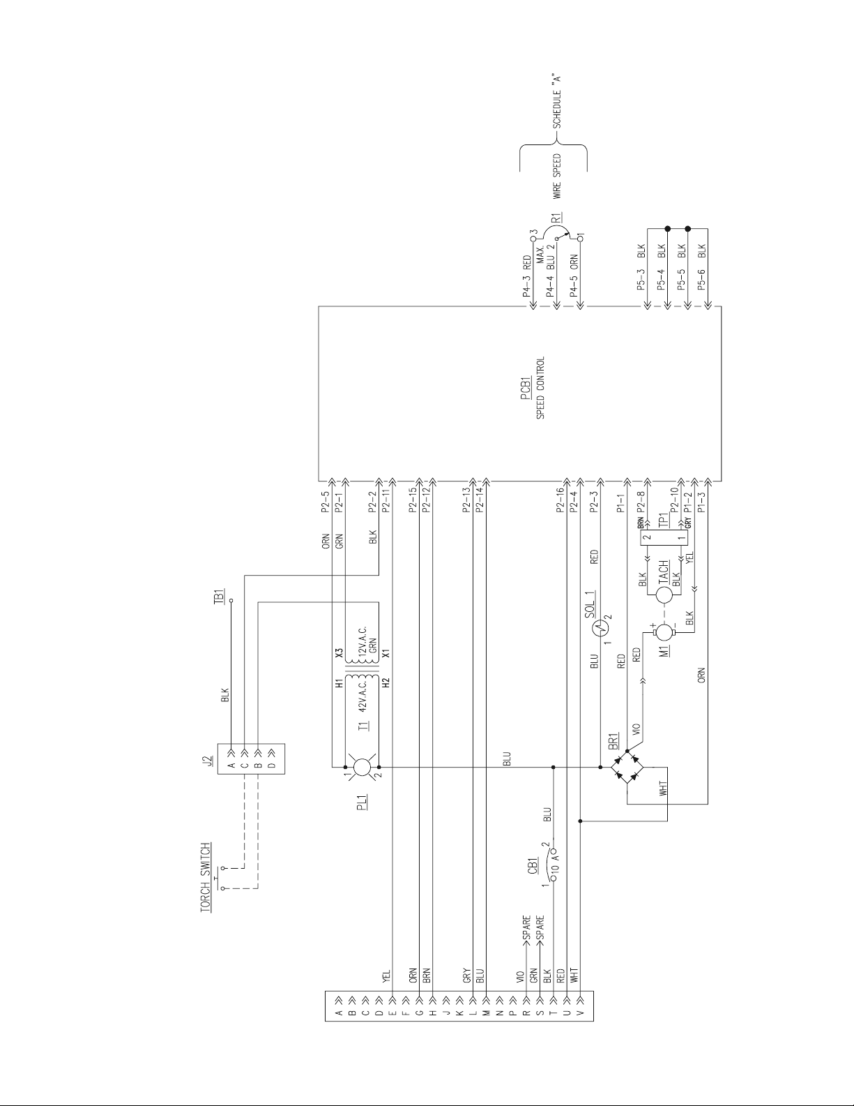
Figure 6-1. Schematic Diagram - Mig 2E Wire Feeder
D-34190-A
13
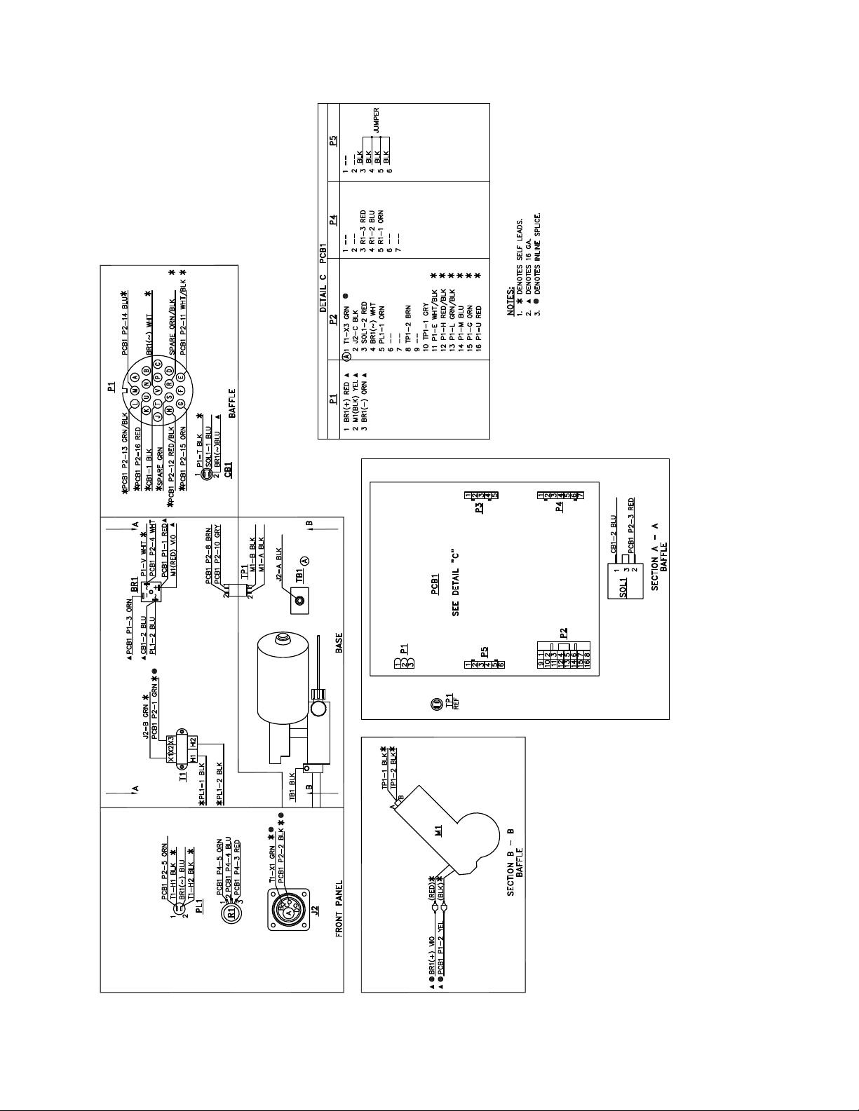
Figure 6-1. Wiring Diagram - Mig 2E Wire Feeder
D-34153-B
14

SECTION 7 REPLACEMENT PARTS
7.1 General.
Replacement Parts are illustrated on the following
figures. When ordering replacement parts, order by
part number and part name, as illustrated on the figure.
DO NOT ORDER BY PART NUMBER ALONE.
Always provide the series or serial number of the unit on
which the parts will be used. The serial number is
stamped on the unit nameplate.
Replacement parts may be ordered from your distributor. Be sure to indicate any special shipping instructions
when ordering replacement parts.
Refer to the Communications Guide on the last page of
this manual for a list of customer service phone numbers.
15

SECTION 7
10
POWER
V
2
3
1
5
4
0
WIRE FEED
SPEED
REPLACEMENT PARTS
1
2
6
7
8
9
10
4
Ite m
No.
1
2
4
5
6
7
8
9
1
1
1
1
1
1
1
1
1
1
1
1
Qty
Req.
Figure 7-1. Mig 2E Wire Feeder (Front View)
Part
No. D escription
32112GY
952924
952929
23612350
23610528
23610696
13730623
32113GY
676876
2062018
13730611
13792157
8,7,6
PANE L, CONTROL
TORCH ADAPTOR ASSY. includes:
C O NN E C TIO N TU B E
POWER LUG
HOUS ING AD A PTOR, STRAIGHT
ADAPTOR, BLOCK ASSEMBLY
LATC H, DOOR
FRONT PANEL
INSULATOR, 10 M IL, NOME X 2X 2.5
P OTENTIOM E TE R, 10 K
KNOB
LIGHT, PILOT
5
Ckt.
Symbol
J2
R1
PL1
16

SECTION 7 REPLACEMENT PARTS
4
1
Item
No.
1
2
3
4
5
6
7
8
8
4
3
2
6
6
7
(DRIVE STAND REMOVED
FOR CLARITY)
Figure 7-2. Mig 2E Wire Feeder (Right Side, Cover Removed)
Qty
Req.
1
4
1
1
1
2
1
1
37712GY
951531
674156
21156
952939
13730583
950823
21165
Part
No. Description
REEL STAND
FOOT MOUNTING
ADAPTER, POWER CABLE, MOLDED
FEED ROLL, .035-.045
DRIVE STA ND, 2-ROLL (See Fig. 7-6)
BUSHING, TE RMINA L
SNAP BUSHING
GUIDE TUBE .035 - .045
Ckt.
Symbol
TB1
TP1, TP2
17

SECTION 7
REPLACEMENT PARTS
3
6
8
10
SEE DETAIL A
1
13
16
14
SEE FIGURE 7-4
2
DETAIL A
Figure 7-3. Mig 2E Wire Feeder (Top View, Cover Removed)
17
4
12
Item
No.
1
2
3
4
6
8
10
12
13
14
16
17
Qty
Req.
1
1
1
2
1
1
1
1
1
10'
1
1
Part
No. Description
34136GY
951530
951174
952860
993717
13792051
13730469
31463
951528
997887
136Z08
35N22
BASE
MOTOR, WIRE F EED
CLAMP, 1 EAR #10 US
CLAMP, 1 EAR #12.8 GER
TRANSFORMER, CONTROL
VALVE , SOLENO ID
RECTIFIER BR IDGE
PC BOARD
CONTROL CA BLE ASS Y, 10 C OND. 19-PIN CONN.
HOS E, WATER
NUT, HOS E
NIPP LE, H OSE
18
Ckt.
Symbol
M1
T1
SOL1
BR1
PCB1

SECTION 7 REPLACEMENT PARTS
7
8
3
9
1
2
Item
No.
1
2
3
4
5
6
7
8
9
10
10
Qty
Req.
2
1
2
1
1
1
1
1
1
1
6
4
5
3
Figure 7-4. Mig 2E Wire Feeder Wire Spool Hub Assembly
Part
No. Description
92040101
23600010
92056007
23600952
23606237
23600255
36756
23600982
63300136
64302037
SCREW R.H.M. 3/8-16X.75
NUT, PLASTIC
WASHER, FLAT 3/8"
WASHER D-TYPE
HUB REEL
BRAKE DISC
"D" S H AF T
SPRING
NUT HEX 3/8-16
WASHER LOC K 3/8
Ckt.
Symbol
19

SECTION 7
REPLACEMENT PARTS
1
7
TOP VIEW
2
8
END VIEW
SIDE VIEW
3
4
5
6
Figure 7-5. Mig 2E Wire Feeder External Views
Item
No.
1
2
3
4
5
6
7
8
Qty
Req.
1
1
1
1
1
1
1
1
Part
2091514
34142YL
34140GY
2062161
98W85
950823
13730222
954698
No. Description
LABEL, WARNING
COVER, TOP
COVER, OPTION, BAFFLE
CIRCUIT BREAKER, 5A
STRAIN RELIEF .875 M.H.
SNAP BUSHI NG
SNAP BUSHI NG
LABEL WARNING PINCH HAZARD
(Inside Cover)
20
Ckt.
Symbol
CB1

SECTION 7 REPLACEMENT PARTS
18
14
10,6
2,4
7,8
9
20
21
1,3
5
11
15
16
12,13
Item
No.
1
2
3
4
5
6
7
8
9
10
11
12
13
14
15
16
17
18
19
20
21
19
Qty
Req.
2
2
3
Figure 7-6. Mig 2-Roll Drive Stand
Part
No. Description
1
1
1
1
1
1
1
1
1
1
1
1
1
1
1
1
1
1
1
952939
952704
23612477
23612475
23612474
23612625
23612472
23612368
23612476
23612460
23612473
23612461
21156
944
952
952925
23612478
34608
952945
952926
23612462
23612662
23612663
2 ROLL WIRE DRIVE S YSTEM, CONSISTS OF:
PRESSURE ARM ASSY., (incls. 2, 3, 4, 7, 8)
AXLE, PRESSURE ROLL
PRESSURE ARM
AXLE NUT
PIVOT PIN
CIRCLIP
PRESSURE ROLL, SMOOTH
SPACER
PRESSURE DEVICE ASSY.
LOCATING PIN
INLET GUIDE
DRIVE ROLL, .035" - .045" (See Table 3-1)
ADAPTOR DRIVE ROLL
FEED ROLL THUMB SCREW
FEED PLATE
WASHER RETAINING SCREW
FEED ROLL SPACER
THUMB SCREW M6X16
SC REW, MOTOR MOUNTING
SPACER TUBE (Pressure Arm)
SPRING PRESSURE ARM
21

SECTION 7
REPLACEMENT PARTS
22

SECTION 7 REPLACEMENT PARTS
INSTRUCTION MANUAL CHANGES
The "A" edition (3/98) corrected some text errors, reformatted Section I, Table 1, and changed the Reel Stand, Feed Roll, Base, Guide Tube,
Top Cover and Option Cover.
The "B" edition (8/99) changed the Water Hose, Drive Stand, Reel Stand, D-Shaft and the Torch Adaptor is now offered completely assembled.
The "C" edition (10/08) updated wiring diagram with revised information per ECN# 083192.
23

ESAB Welding & Cutting Products, Florence, SC Welding Equipment
COMMUNICATION GUIDE - CUSTOMER SERVICES
A. CUSTOMER SERVICE QUESTIONS:
Order Entry Product Availability Pricing Delivery
Order Changes Saleable Goods Returns Shipping Information
Telephone: (800)362-7080 / Fax: (800) 634-7548
Telephone: (800)783-5360 / Fax: (800) 783-5362
Telephone: (800) 235-4012/ Fax: (888) 586-4670
B. ENGINEERING SERVICE: Telephone: (843) 664-4416 / Fax : (800) 446-5693
Welding Equipment Troubleshooting Hours: 7:30 AM to 5:00 PM EST
Warranty Returns Authorized Repair Stations
C. TECHNICAL SERVICE: Telephone: (800) ESAB-123/ Fax: (843) 664-4452
Part Numbers Technical Applications Hours: 8:00 AM to 5:00 PM EST
Performance Features Technical Specifications Equipment Recommendations
D. LITERATURE REQUESTS: Telephone: (843) 664-5562 / Fax: (843) 664-5548
E. WELDING EQUIPMENT REPAIRS: Telephone: (843) 664-4487 / Fax: (843) 664-5557
Repair Estimates Repair Status Hours: 7:30 AM to 3:30 PM EST
F. WELDING EQUIPMENT TRAINING:
Telephone: (843)664-4428 / Fax: (843) 679-5864
Training School Information and Registrations Hours: 7:30 AM to 4:00 PM EST
G. WELDING PROCESS ASSISTANCE:
Telephone: (800) ESAB-123 / Fax: (843) 664-4454 Hours: 7:30 AM to 4:00 PM EST
H. TECHNICAL ASST. CONSUMABLES:
Telephone : (800) 933-7070 Hours: 7:30 AM to 5:00 PM EST
Eastern Distribution Center
Central Distribution Center
Western Distribution Center
Hours: 7:30 AM to 4:00 PM EST
Telephone: (800) ESAB-123/ Fax: (843) 664-4452/ Web:http://www.esab.com
F15-143-C 10 / 08 PRINTED IN U.S.A.
IF YOU DO NOT KNOW WHOM TO CALL
Hours: 7:30 AM to 5:00 PM EST
 Loading...