

Page 1
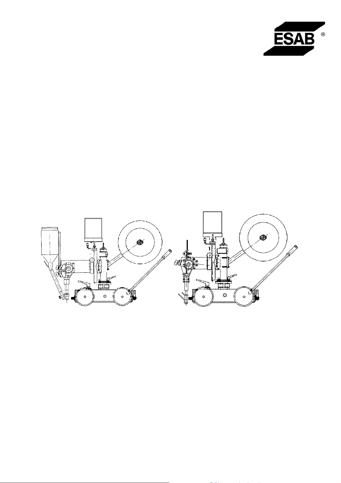
A6 Mastertrac
A6 TFE1/A6 TFE2/A6 TGE1
101103105107109111102021110025108024042106023061104022041100020040060001
Bruksanvisning
Brugsanvisning
Bruksanvisning
Käyttöohjeet
Instruction manual
Betriebsanweisung
Manuel d’instructions
Gebruiksaanwijzing
Instrucciones de uso
Istruzioni per l’uso
Manual de instruções
ПдзгЯет чсЮуещт
Valid for serial no. 725--xxx--xxxx0456 503 001 2004--12--02
Page 2

SVENSKA 5..............................................
DANSK 22................................................
NORSK 39................................................
SUOMI 56................................................
ENGLISH 73..............................................
DEUTSCH 90.............................................
FRANÇAIS 107.............................................
NEDERLANDS 124.........................................
ESPAÑOL 141..............................................
ITALIANO 158..............................................
PORTUGUÊS 175..........................................
ЕЛЛЗНЙКБ 192.............................................
Rätt till ändring av specifikationer utan avisering förbehålles.
Ret til ændring af specifikationer uden varsel forbeholdes.
Rett til å endre spesifikasjoner uten varsel forbeholdes.
Oikeudet muutoksiin pidätetään.
Rights reserved to alter specifications without notice.
Änderungen vorbehalten.
Sous réserve de modifications sans avis préalable.
Recht op wijzigingen zonder voorafgaande mededeling voorbehouden.
Reservado el derecho de cambiar las especificaciones sin previo aviso.
Specifiche senza preavviso.
Reservamo--nos o direito de alterar as especificações sem aviso prévio.
ДйбфзсеЯфбй фп дйкбЯщмб фспрпрпЯзузт рспдйбгсбцюн ЧщсЯт рспейдпрпЯзуз.
-- 2 --
Page 3

FÖRSÄKRAN OM ÖVERENSST ÄMMELSE
Esab Welding Equipment AB, 695 81 Laxå, Sweden, försäkrar under eget ansvar att
svetsautomat A6 T F E1/TFE2/TGE1 från serienummer 725 är i överensstämmelse
med standard EN 60292 enligt villkoren i direktiv 89/392/EEG med tillägg.
-- -- -- -- -- -- -- -- -- -- -- -- -- -- -- -- -- -- -- -- -- -- -- -- -- -- -- -- -- -- -- -- -- -- -- -- -- -- -- -- -- -- -- -- -- -- -- -- -- -- -- -- -- -- -- -- -- -- -- -- -- -- -- --------
OVERENSSTEMMELSEERKLÆRING
Esab Welding Equipment AB, 695 81 Laxå, Sweden garanterer under eget ansvar,
at svejseautomat A6 TFE1/TFE2/TGE1 fra serienummer 725 er i overensstemmelse
med standard EN 60292 ifølge betingelserne i direktiv 89/392/EEC med tillægg.
-- -- -- -- -- -- -- -- -- -- -- -- -- -- -- -- -- -- -- -- -- -- -- -- -- -- -- -- -- -- -- -- -- -- -- -- -- -- -- -- -- -- -- -- -- -- -- -- -- -- -- -- -- -- -- -- -- -- -- -- -- -- -- --------
FORSIKRING OM OVERENSSTEMMELSE
Esab Welding Equipment AB, 695 81 Laxå, Sweden, forsikrer på eget ansvar at
sveiseautomat A6 TFE1/TFE2/TGE1 med serienummer 725 er i samsvar med standard EN 60292 i overensstemmelse med bestemmelsene i direktiv 89/392/EØF med
tillegg.
-- -- -- -- -- -- -- -- -- -- -- -- -- -- -- -- -- -- -- -- -- -- -- -- -- -- -- -- -- -- -- -- -- -- -- -- -- -- -- -- -- -- -- -- -- -- -- -- -- -- -- -- -- -- -- -- -- -- -- -- -- -- -- --------
VAATIMUSTENMUKAISUUSVAKUUTUS
Esab Welding Equipment AB, 695 81 Laxå, Sweden, vakuuttaa omalla vastuullaan,
että hitsausautomaatti A6 TFE1/TFE2/TGE1 sarjanumerosta 725 täyttää standardin
EN 60292 vaatimukset direktiivin 89/392/EEC ja sen lisäyksen mukaisesti.
-- -- -- -- -- -- -- -- -- -- -- -- -- -- -- -- -- -- -- -- -- -- -- -- -- -- -- -- -- -- -- -- -- -- -- -- -- -- -- -- -- -- -- -- -- -- -- -- -- -- -- -- -- -- -- -- -- -- -- -- -- -- -- --------
DECLARATION OF CONFORMITY
Esab Welding Equipment AB, 695 81 Laxå, Sweden, gives its unreserved guarantee
that automatic welding machine A6 TFE1/TFE2/TGE1 from serial number 725 complies with standard EN 60292, in accordance with the requirements of directive
89/392/EEA and addendum.
-- -- -- -- -- -- -- -- -- -- -- -- -- -- -- -- -- -- -- -- -- -- -- -- -- -- -- -- -- -- -- -- -- -- -- -- -- -- -- -- -- -- -- -- -- -- -- -- -- -- -- -- -- -- -- -- -- -- -- -- -- -- -- --------
KONFORMITÄTSERKLÄRUNG
Esab Welding Equipment AB, 695 81 Laxå Sweden, versichert hiermit auf eigene
Verantwortung, daß der Schweißautomat A6 TFE1/TFE2/TGE1 ab Serien--Nr 725
mit der norm EN 60292 gemäß den Bedingungen der Richtlinien 89/392/EWG mit
der Ergänzung in Übereinstimmung steht.
-- -- -- -- -- -- -- -- -- -- -- -- -- -- -- -- -- -- -- -- -- -- -- -- -- -- -- -- -- -- -- -- -- -- -- -- -- -- -- -- -- -- -- -- -- -- -- -- -- -- -- -- -- -- -- -- -- -- -- -- -- -- -- --------
CERTIFICAT DE CONFORMITÉ
Esab Welding Equipment AB, 695 81 Laxå Sweden, certifie sous sa propre responsabilité que la appareil de soudage automatique A6 TFE1/TFE2/TGE1 à partir du
numéro de serié 725 répond aux normes de qualité EN 60292 conformément aux
directives 89/392/EEC avec annexe.
-- -- -- -- -- -- -- -- -- -- -- -- -- -- -- -- -- -- -- -- -- -- -- -- -- -- -- -- -- -- -- -- -- -- -- -- -- -- -- -- -- -- -- -- -- -- -- -- -- -- -- -- -- -- -- -- -- -- -- -- -- -- -- --------
OVEREENKOMSTIGHEIDSVERKLARING
Esab Welding Equipment AB, 695 81 Laxå Sweden, verklaart op eigen verantwoordelijkheid dat lasautomaat A6 TF E1/TF E2/TGE1 van serienummer 725 overeenkomt
met norm EN 60292 volgens richtlijn 89/392/EEG van de Raad m e t toevoeging.
-- -- -- -- -- -- -- -- -- -- -- -- -- -- -- -- -- -- -- -- -- -- -- -- -- -- -- -- -- -- -- -- -- -- -- -- -- -- -- -- -- -- -- -- -- -- -- -- -- -- -- -- -- -- -- -- -- -- -- -- -- -- -- --------
DECLARACIÓN DE CONFORMIDAD
Esab Welding Equipment AB, 695 81 Laxå, Sweden, declara, asumiendo toda responsabilidad, que la equipo para soldadura automática A6 TFE1/TFE2/TGE1 desde
el número de serie 725 está fabricada de conformidad con la normativa EN 60292
según los requisitos de la directiva 89/392/EEC con el suplemento.
-- -- -- -- -- -- -- -- -- -- -- -- -- -- -- -- -- -- -- -- -- -- -- -- -- -- -- -- -- -- -- -- -- -- -- -- -- -- -- -- -- -- -- -- -- -- -- -- -- -- -- -- -- -- -- -- -- -- -- -- -- -- -- --------
3
Page 4
DICHIARAZIONE DI CONFORMITA
Esab Welding Equipment AB, 695 81 Laxå Sweden, dichiara sotto la propria responsabilità che la saldatrice automatica A6 TFE1/TFE2/TGE1 dal numero di serie 725 è
conforme alla norma EN 60292 ai sensi dei requisiti previsti dalla direttiva
89/392/CEE e successive integrazioni nella direttiva.
-- -- -- -- -- -- -- -- -- -- -- -- -- -- -- -- -- -- -- -- -- -- -- -- -- -- -- -- -- -- -- -- -- -- -- -- -- -- -- -- -- -- -- -- -- -- -- -- -- -- -- -- -- -- -- -- -- -- -- -- -- -- -- --------
DECLARAÇÃO DE CONFORMIDADE
Esab Welding Equipment AB, 695 81 Laxå Sweden, certifica, sob a sua própria responsabilidade que, a equipamento autom ático para soldadura A6 TFE1/TFE2/TGE1
desde número de série 725 está em conformidade com a norma EN 60292, segundo os requisitos constantes na directiva 89/392/EEC e com o suplemento.
-- -- -- -- -- -- -- -- -- -- -- -- -- -- -- -- -- -- -- -- -- -- -- -- -- -- -- -- -- -- -- -- -- -- -- -- -- -- -- -- -- -- -- -- -- -- -- -- -- -- -- -- -- -- -- -- -- -- -- -- -- -- -- --------
ВЕВБЙЩУЗ УШМЦЩНЙБУ
Ç Esab Welding Equipment AB, 695 81 Laxå Sweden, вевбйюней ме дйкЮ фзт ехиэнз
oфй з бхфьмбфт ухгкпллзфЮт A6 TFE1/TFE2/TGE1 брь фпн бсйимь уейсЬт 725
всЯукефбй уе ухмцщнЯб ме фп уфбнфбсф ЕН 60292 уэмцщнб ме фпх ьспхт фзт
пдзгЯбт 89/392/ЕЕC кбй фзн рспуиЮкз.
-- -- -- -- -- -- -- -- -- -- -- -- -- -- -- -- -- -- -- -- -- -- -- -- -- -- -- -- -- -- -- -- -- -- -- -- -- -- -- -- -- -- -- -- -- -- -- -- -- -- -- -- -- -- -- -- -- -- -- -- -- -- -- -------Laxå 97--04--15
Paul Karlsson
Managing Director
Esab Welding Equipment AB
695 81 LAXÅ
SWEDEN Tel: + 46 584 81176 Fax: + 46 584 12336
4
Page 5

ENGLISH
1SAFETY 74...........................................................
2 INTRODUCTION 76...................................................
2.1 General 76..................................................................
2.2 Technical data 76............................................................
2.3 Welding method 77...........................................................
2.4 Horizontal Welding or Welding on an Inclined Plane 77............................
2.5 Equipment 78................................................................
3 INSTALLATION 80....................................................
3.1 General 80..................................................................
3.2 Connections 80..............................................................
4 OPERATION 82.......................................................
4.1 General 82..................................................................
4.2 Starting work 82..............................................................
4.3 Refilling with flux powder (submerged--arc welding) 87............................
4.4 Conversion of A6 TFE1 (Submerged-- arc welding) to MIG/MAG welding 87..........
4.5 Conversion of A6 TFE1 / A6 SFE2 (Submerged--arc welding) to Twin--arc 87.........
5 MAINTENANCE 88....................................................
5.1 General 88..................................................................
5.2 Daily 88.....................................................................
5.3 Regularly 88.................................................................
6 TROUBLESHOOTING 89..............................................
6.1 General 89..................................................................
6.2 Possible faults 89............................................................
7 ORDERING OF SPARE PARTS 89......................................
WEAR COMPONENTS 211..............................................
SPARE PARTS LIST 215................................................
TOCe
-- 7 3 --
Page 6

GB
1SAFETY
Users of ESAB welding equipment have the ultimate responsibility for ensuring that anyone who
works on or near the equipment observes all the relevant safety precautions. Safety precautions
must meet the requirements that apply to this type of welding equipment. The following recommendations should be observed in addition to the standard regulations that apply to the workplace.
All work must be carried out by trained personnel well--acquainted with the operation of the welding
equipment. Incorrect operation of the equipment may lead to hazardous situations which can result
in injury to the operator and damage to the equipment.
1. Anyone who uses the welding equipment must be familiar with:
S its operation
S location of emergency stops
S its function
S relevant safety precautions
S welding
2. The operator must ensure that:
S no unauthorised person is stationed within the working area of the equipment when it is
started up.
S no--one is unprotected when the arc is struck
3. The workplace must:
S be suitable for the purpose
S be free from draughts
4. Personal safety equipment
S Always wear recommended personal safety equipment, such as safety glasses, flame--proof
clothing, safety gloves.
S Do not wear loose--fitting items, such as scarves, bracelets, rings, etc., which could become
trapped or cause burns.
5. General precautions
S Make sure the return cable is connected securely.
S Work on high voltage equipment may only be carried out by a qualified electrician.
S Appropriate fire extinquishing equipment must be clearly marked and close at hand.
S Lubrication and maintenance must not be carried out on the equipment during operation.
Welding on an Inclined Plane -- In the Travel Direction or Sideways
Mind the following:
S That the freewheel clutch of the gear shall be in locked position.
S That, if the operator leaves the machine, it shall be parked with blocks in front of the wheels, in
order to prevent the machine from moving unintentionally.
S Make sure that the automatic welding machine is not unstable before start.
S That the placement of the welding head and the wire reel influence the centre of gravity of the
machine.
Too high a centre of gravity means an unstable welding machine.
S That the consumption of wire and flux results in displacement of the weight distribution during the
welding.
ffa8safE
-- 7 4 --
Page 7
GB
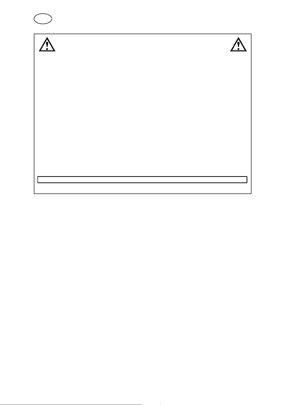
WARNING
ARC WELDING AND CUTTING CAN BE INJURIOUS TO YOURSELF AND OTHERS. TAKE PRECAUTIONS WHEN WELDING. ASK FOR YOUR EMPLOYER’S SAFETY PRACTICES WHICH SHOULD BE
BASED ON MANUFACTURERS’ HAZARD DATA.
ELECTRIC SHOCK -- Can kill
S Install and earth the welding unit in accordance with applicable standards.
S Do not touch live electrical parts or electrodes with bare skin, wet gloves or wet clothing.
S Insulate yourself from earth and the workpiece.
S Ensure your working stance is safe.
FUMES AND GASES -- Can be dangerous to health
S Keep your head out of the fumes.
S Use ventilation, extraction at the arc, or both, to take fumes and gases away from your breathing zone
and the general area.
ARC RAYS -- Can injure eyes and burn skin.
S Protect your eyes and body. Use the correct welding screen and filter lens and wear protective
clothing.
S Protect bystanders with suitable screens or curtains.
FIRE HAZARD
S Sparks (spatter) can cause fire. Make sure therefore that there are no inflammable materials nearby.
NOISE -- Excessive noise can damage hearing
S Protect your ears. Use earmuffs or other hearing protection.
S Warn bystanders of the risk.
MALFUNCTION -- Call for expert assistance in the event of malfunction.
READ AND UNDERSTAND THE INSTRUCTION MANUAL BEFORE INSTALLING OR OPERATING.
PROTECT YOURSELF AND OTHERS!
ffa8safE
-- 7 5 --
Page 8
A
GB
2 INTRODUCTION
2.1 General
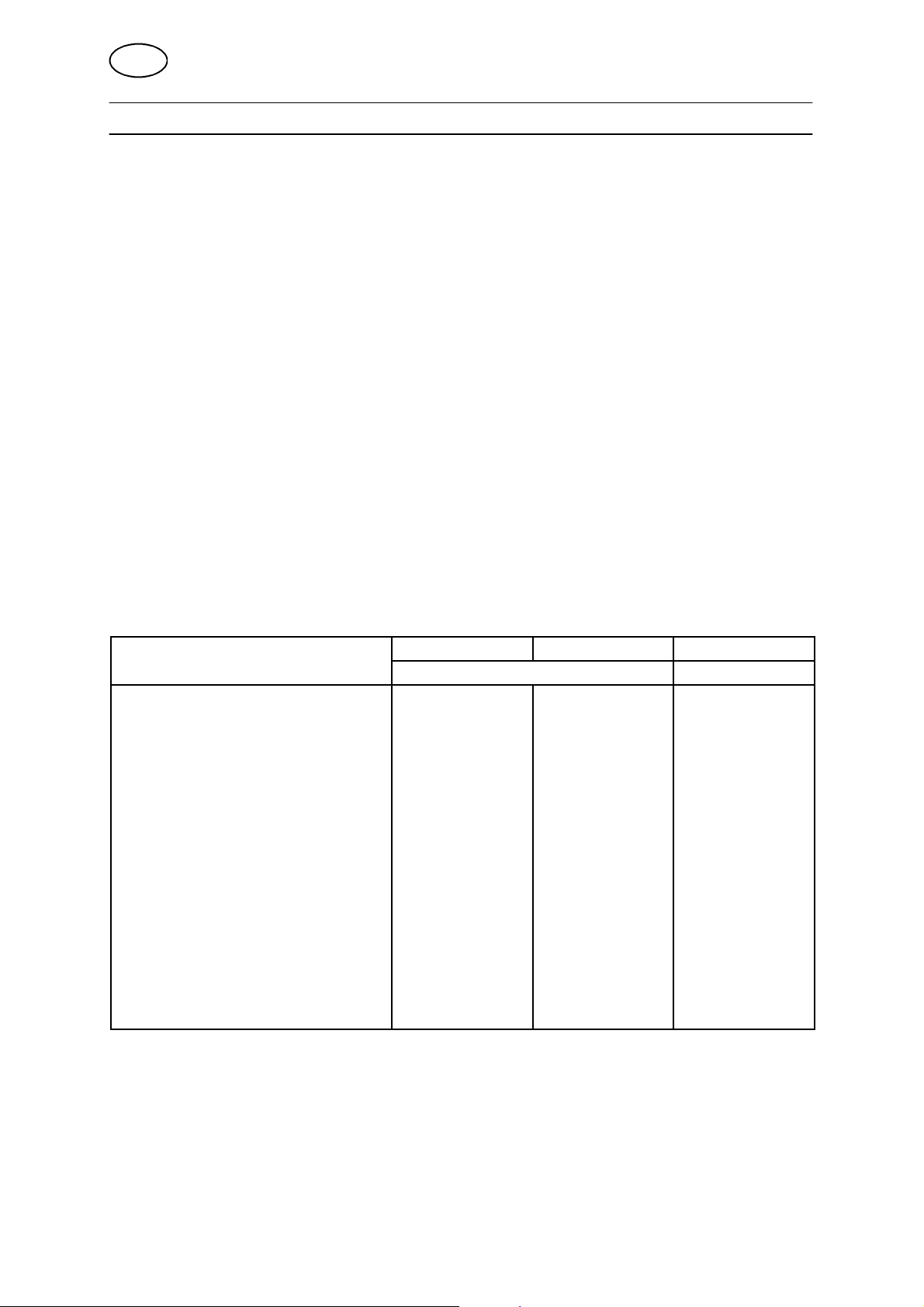
The A6 TFE1 automatic welding machine is mounted on a self--propelled trolley
and is designed for submerged--arc welding of butt and fillet welds.
The A6 TFE2 automatic welding machine, with two welding heads, is mounted on
a self --propelled trolley and is designed for submerged--arc welding of butt welds.
The A6 TGE1 automatic welding machine is mounted on a self--propelled trolley
and is designed for M IG/MAG welding of butt and fillet welds.
All other uses are prohibited.
The automatic welding machines are used in conjunction with ESABÕs control box
A2--A6 Process Controller (PEH).
The supply voltage to the control box and to the welding machine motors is provided
by ESAB’s welding power sources LAF and TAF.
The position of welding head can be set horizontally and vertically with the linear
slides. Angular movement is adjusted with the angular slide.
2.2 Technical data
6 Mastertrac
Supply voltage 42 V AC 42 V AC 42 V AC
Rated load 100 % 1500 A DC/AC 1500 A DC/AC 600 A DC
Electrode dimensions:
solid single wire 3.0--6.0 mm 3.0--6.0 mm 1.0--2.4 mm
flux--cored wire 3.0--4.0 mm 3.0--4.0 mm 1.6--3.2 mm
twin wire 2x2.0--3.0 2x2.0--3.0mm -- -Electrode feed rate, max. 4m/min 4m/min 16 m/min
Brake drum braking torque 1.5 Nm 1.5 Nm 1.5 Nm
Speed of travel 0.1--2.0 m/min 0.1--2.0 m/min 0.1--2.0 m/min
Electrode weight, max. 30 kg 2x15kg 30 kg
Flux hopper capacity
(Must not be filled with preheated flux)
Weight (excluding electrode and flux) 110 kg 158 kg 100 kg
Continuous A weighted sound pressu-
re
A6 TFE1 A6 TFE2 A6 TGE1
Submerged--arc MIG/MAG
10 l 10 l -- --
68 dB 68 dB 83 dB
ffa8d1ea
-- 7 6 --
Page 9

GB
2.3 Welding method
Submerged--arc welding
For submerged--arc welding, an A6 Mastertrac of type A6 TF is used, which is
available in several different versions:
S Submerged --arc Light duty
Submerged-- arc light duty, with a ∅ 20 mm connector, which permits a load of up
to 800 A (100%) or 1000 A (60%).
S Submerged--arc Heavy duty
Submerged-- arc heavy duty, with a ∅ 35 mm connector, which permits a load of
up to 1500 A.
Both versions can be equipped with feed rollers for single or twin wire welding
(twin-- arc). A special knurled feed roller is available for flux --cored wire, which
guarantees even wire feed without the risk of deformation due to high feed pressure.
For work in confined spaces, (smaller than 50 cm), a special welding head of type
A6 SFE1C is available, which can be installed on the Mastertrac as required.
Tandem welding (submerged--arc)
For tandem welding, a welding head of type A6 TFE2 is always used, which must be
connected to 2 welding power sources and 2 control boxes of type A2--A6 Process
Controller.
The tandem welding head includes 2 single welding heads (A6 SF), each with its
own contact tip. Each contact tip has a maximum rated load of 1500 A.
MIG/MAG welding
For MIG/MAG welding, an A6 Mastertrac A6 TGE1 is used, which has a maximum
rated load of 600 A. The welding head is water cooled, with the cooling water
supplied by hoses from connections intended for the purpose.
2.4 Horizontal Welding or Welding on an Inclined Plane
The automatic welding machines are designed for horizontal welding in the first
place.
Read the section Welding on an Inclined Plane - In the Travel Direction o r
Sideways, on page 74.
ffa8d1ea
-- 7 7 --
Page 10
GB
2.5 Equipment
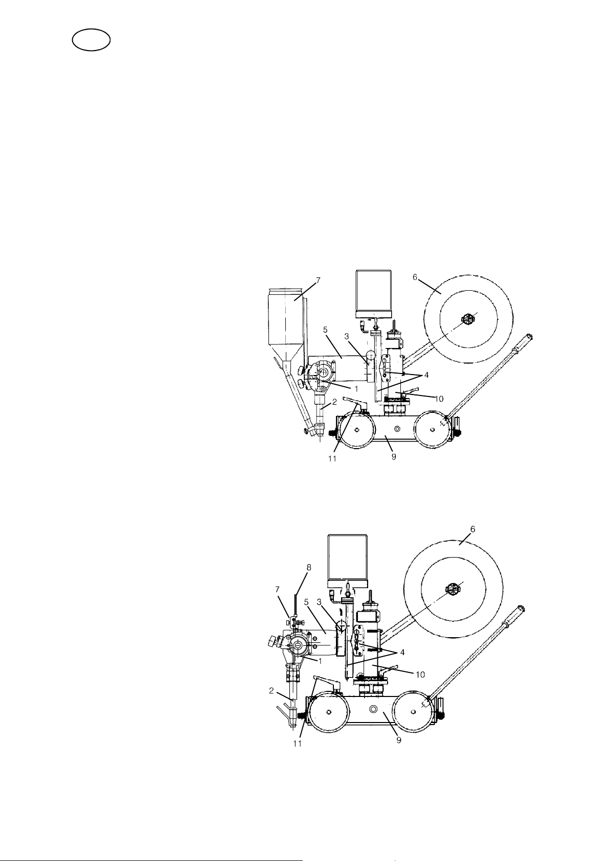
Included in a complete welding head are a feed motor (A6 VEC) to feed in the wire
and contact equipment which supplies current to the wire and provides a good
contact.
Contact equipment is available in several different versions.
S A6 TF is used for submerged--arc welding.
S A6 TG is used for MIG/MAG welding.
Main components of the A6 TFE1 and A6 TFE2
1. Straightener.
2. Contact equipment which
consists of a contact tip,
connector and flux tube.
3. Angular slide
4. Slide (motor or handdriven)
5. Motor and gearbox (A6 VEC)
6. Wire drum
7. Flux hopper (may be
fitted with a cyclone)
8. --
9. Trolley
10. Column
11. Disengagement lever
Main components of the A6 TGE1
1. Straightener.
2. Contact equipment which
consists of a connector, gas
nozzle and water hoses.
3. Angular slide.
4. Slide (motor or hand driven).
5. Motor and gearbox (A6 VEC).
6. Wire drum.
7. Fine wire straightener.
8. Wire guide.
9. Trolley.
10. Column.
11. Disengagement lever.
ffa8d1ea
-- 7 8 --
Page 11
GB
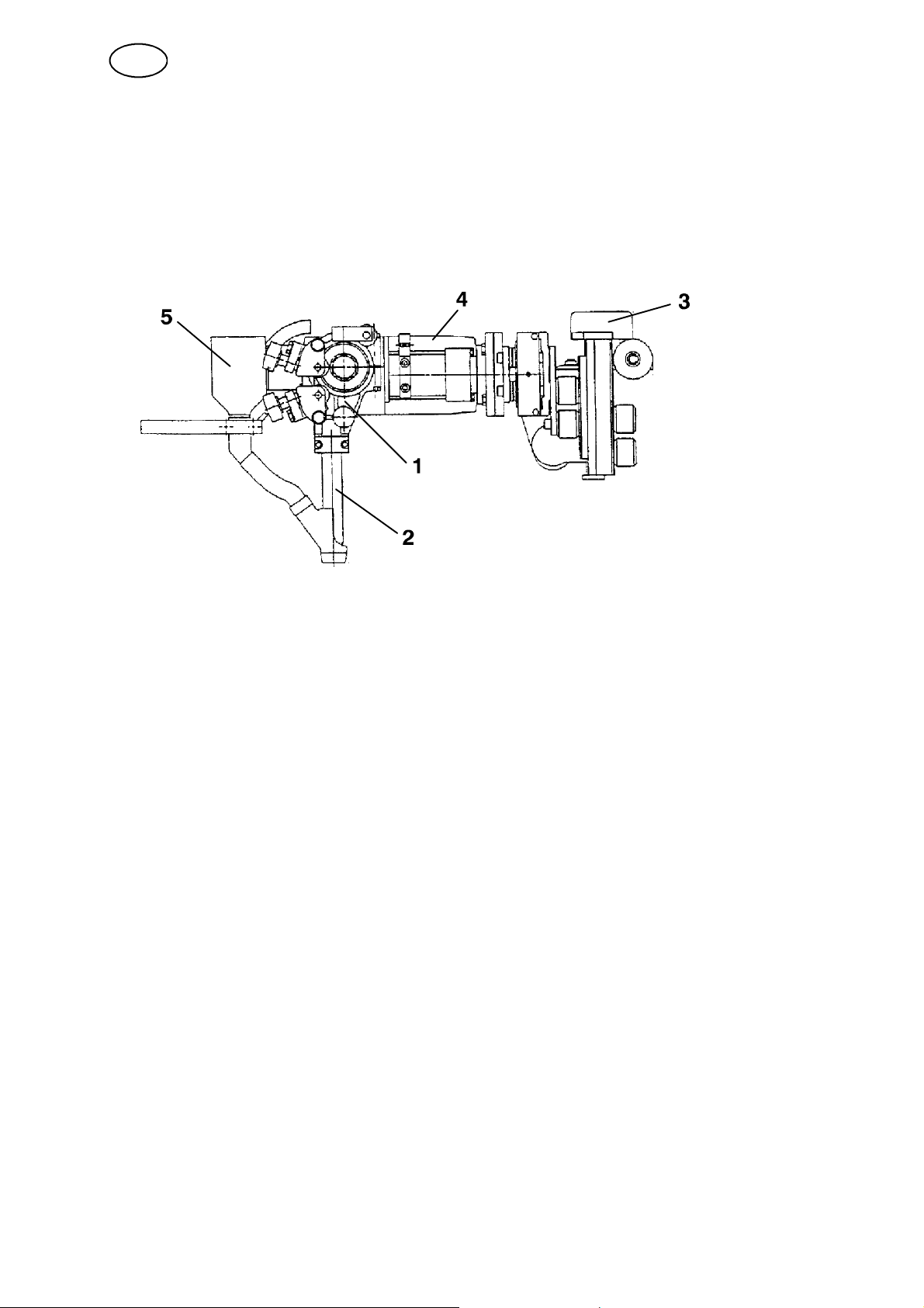
Example of the A6 SFE1C, which can be mounted on an A6 Mastertrac
1. Straightener.
2. Contact equipment, which consists of a contact tip, connector and flux tube.
3. Slide (motor driven).
4. Motor and gearbox (A6 VEC).
5. Flux hopper (1 l).
For connection instructions for submerged--arc and MIG/MAG welding, see page 80.
ffa8d1ea
-- 7 9 --
Page 12
GB
3 INSTALLATION
3.1 General
The installation must be executed by a professional.
WARNING
Rotating parts can cause injury, take great care.
3.2 Connections
3.2.1 General
S Connection of the control box A2--A6 Process Controller (PEH) to the automatic
welding machine is carried out prior to delivery.
For further information, see instruction manual for the A2--A6 Process Controller
(PEH).
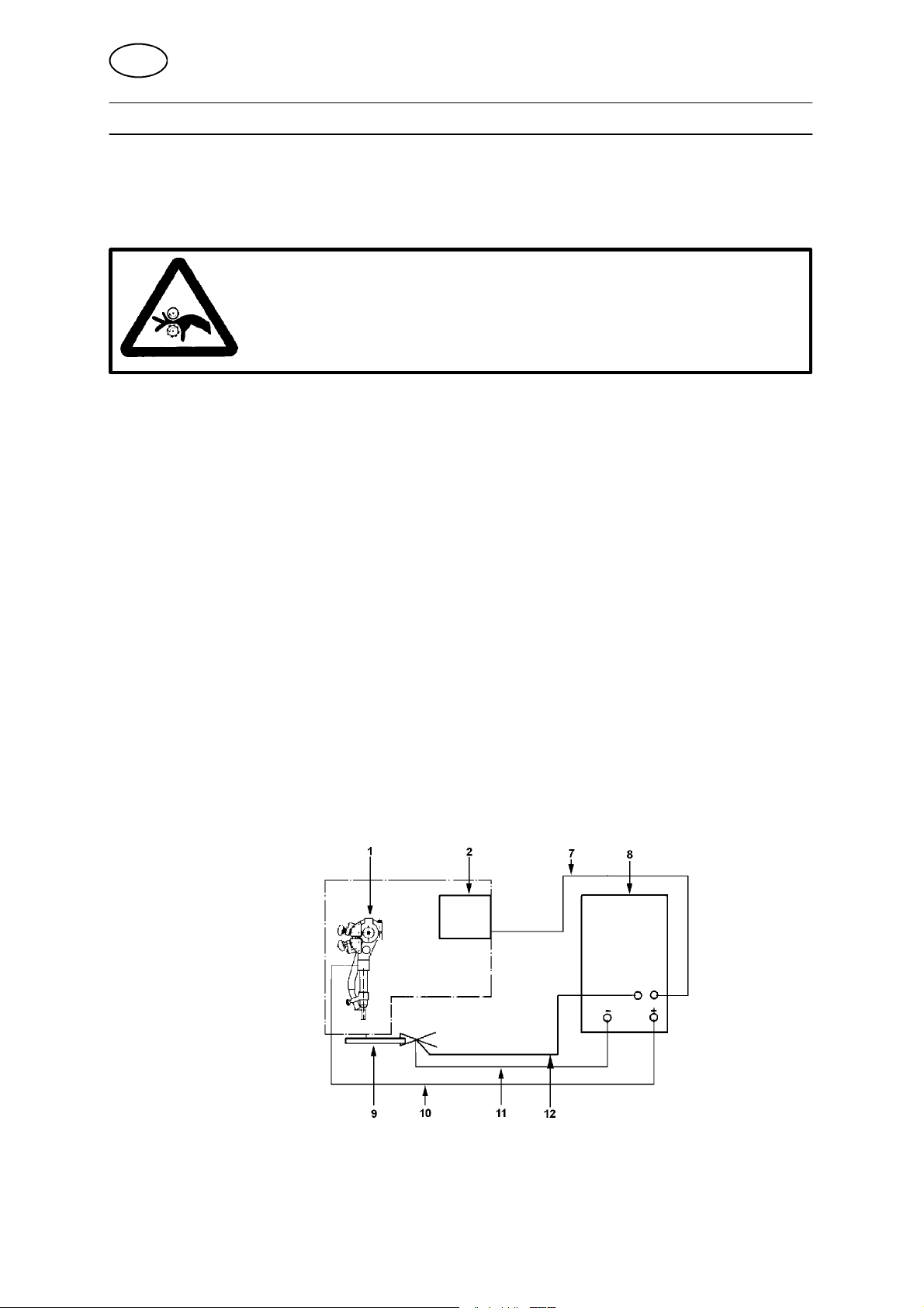
S Connect the A6 Mastertrac in accordance with the following diagrams.
3.2.2 Submerged--Arc Welding (SAW)
S Connect the control cable (7) between the welding power source (8) and the
control box PEH (2).
S Connect the return cable (11) between the welding power source (8) and the
work piece (9).
S Connect the welding cable (10) between the welding power source (8) and the
automatic welding machine (1).
S Connect the measuring cable (12) between the welding power source (8) and
the work piece (9).
ffa8i1ea
-- 8 0 --
Page 13
GB
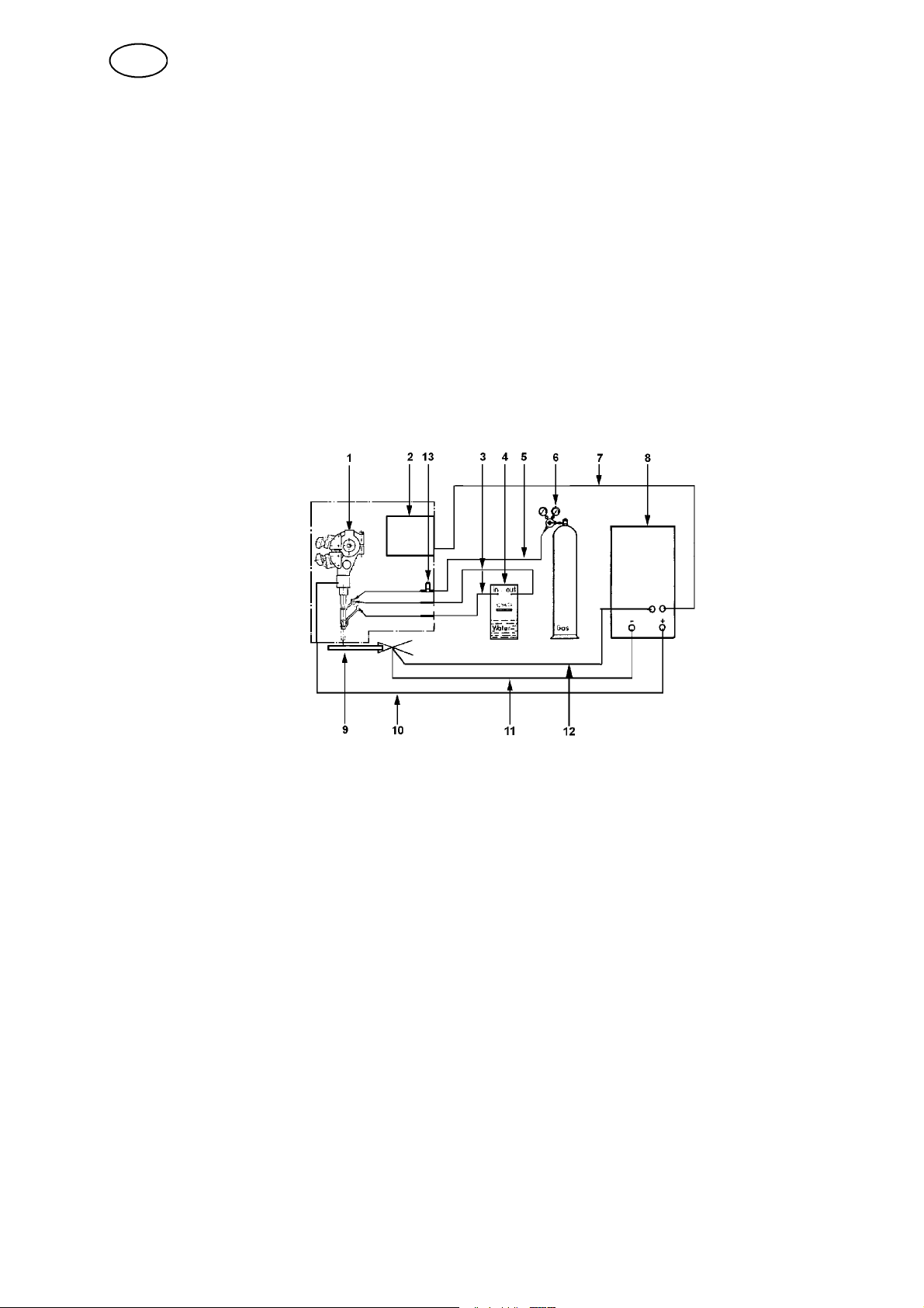
3.2.3 Gas Metal Arc Welding (MIG/MAG)
S Connect the control cable (7) between the welding power source (8) and the
control box A2--A6 Process Controller (PEH) (2).
S Connect the return cable (11) between the welding power source (8) and the
work piece (9).
S Connect the welding cable (10) between the welding power source (8) and the
automatic welding machine (1).
S Connect the gas pipe (5) between the reduction valve (6) and the gas valve on
the automatic welding machine (13).
S Connect the hoses for cooling water (3) between the cooling unit (4) and the
automatic welding machine (1).
S Connect the measuring cable (12) between the welding power source (8) and
the work piece (9).
ffa8i1ea
-- 8 1 --
Page 14
GB
4 OPERATION
4.1 General
General safety regulations for the handling of the equipment can be found on
page 74. Read through before you start using the equipment!
S Select wire type and flux powder or shielding gas so that the weld material is as
close as possible to the analysis of the base metal. Select wire size and welding
data in accordance with the values recommended by the welding materials
supplier.
S Thorough preparation of the weld surfaces is necessary to achieve a good weld.
NOTE! The width of the weld joint gap must be uniform.
S To minimise the risk of heat crack formation, the width of the weld must be
greater than the penetration depth.
S Always carry out a test weld with the same joint type and sheet thickness as the
production work piece.
S For control and adjustment of the automatic welding m achine and welding power
supply, see the instruction manual for the A2--A6 Process Controller (PEH).
S The trolley can be moved manually after disengaging the disengagement lever,
see the diagram on page 78.
S When changing consumables, see table on page 211.
4.2 Starting work
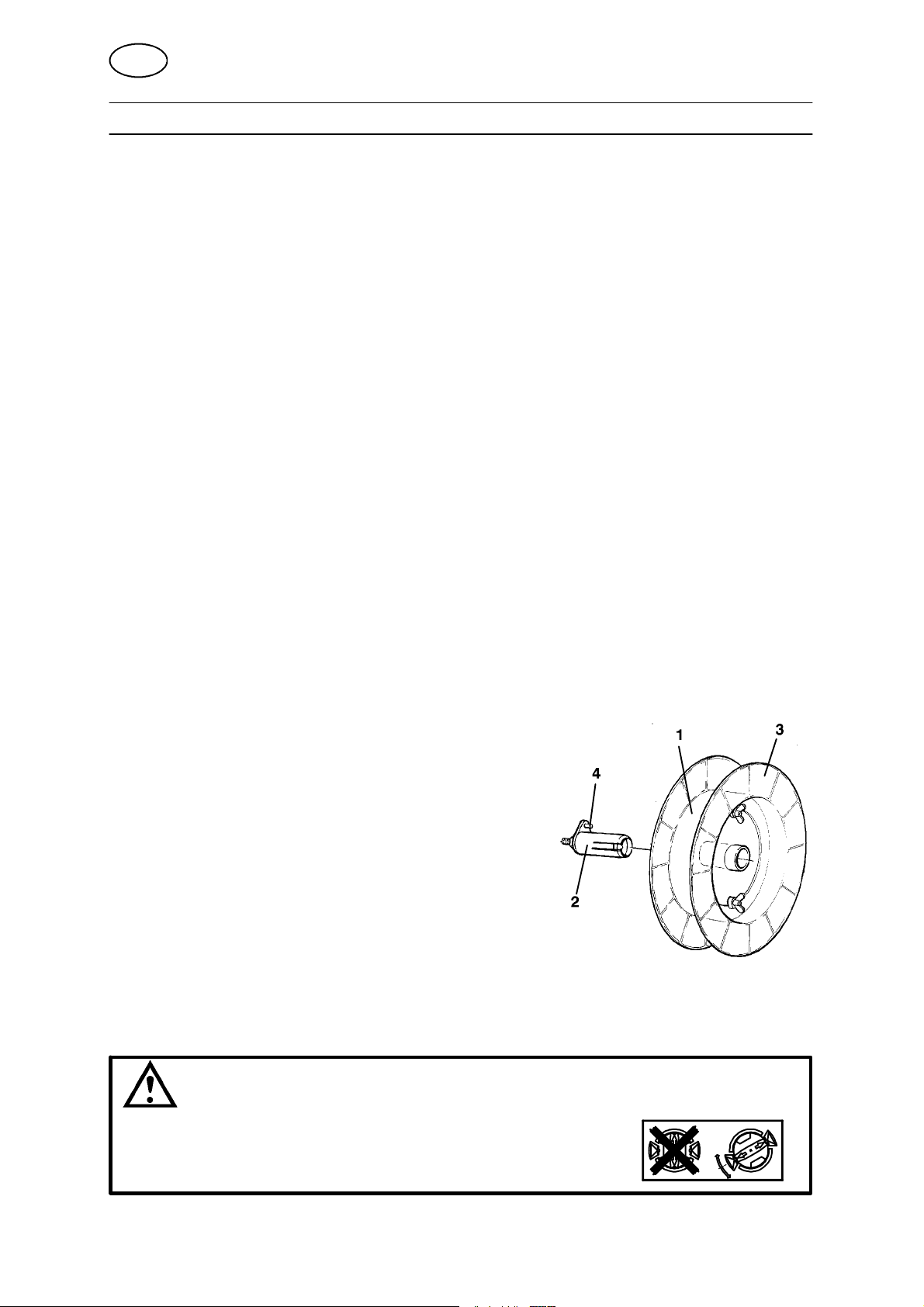
Loading the welding wire
S Remove the wire drum (1) from the brake hub (2)
and take off the side plate (3).
S Locate the wire reel on the wire drum (1).
S Cut off the binding wires from around the
wire reel.
S Replace the side plate (3).
S Replace the wire drum (1) on the brake hub (2).
Check that the carrier (4) is in the correct position.
NOTE! The maximum angle for the wire bobbin is 25¡.
At extreme angles, wear will occur on the brake hub locking
mechanism and the wire bobbin will slide off the brake hub.
WARNING
To prevent the reel sliding off the hub:
S
Lock the reel in place by turning the red knob as shown
on the warning label attached next to the hub.
ffa8o1ea
-- 8 2 --
Page 15
GB
SAW MIG/MAG
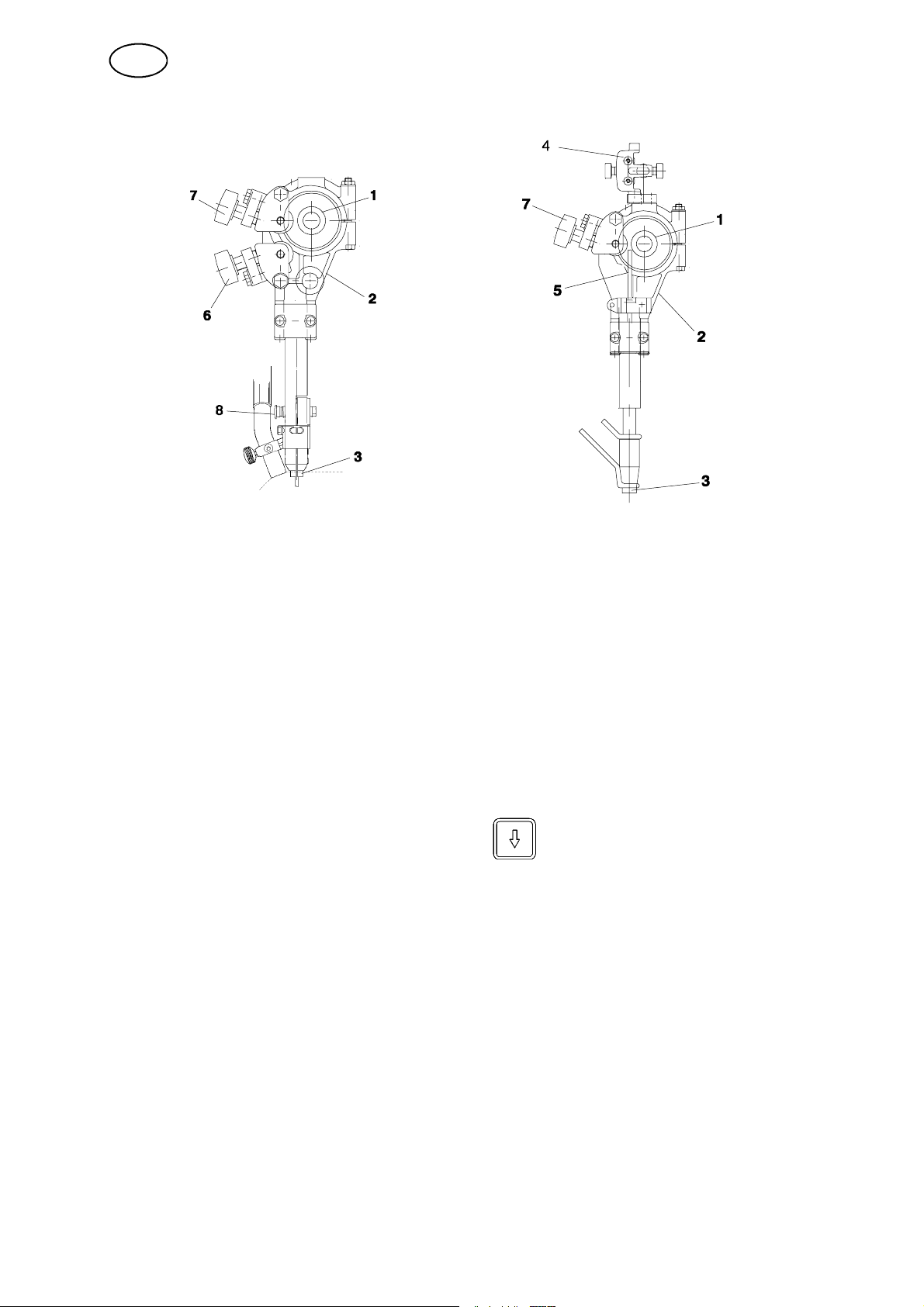
S Check that the feed roller (1) and contact jaw or contact tip (3) are of the correct
dimension for the selected wire size.
S Pull the end of the wire through the straightener (2). For a wire diameter greater
than 2 mm; straighten out 0.5 m of wire and feed it by hand down through the
straightener.
S Locate the end of the wire in the feed roller (1) groove.
S Set the wire tension on the feed roller with the knob (7). Note! Do not tension
more than is required to achieve an even feed.
S The pressure screw (8) must not be dismantled. (Applies to Submerged --arc
Heavy duty).
S Feed the wire forward 30 mm by pressing on the control box
A2--A6 Process Controller.
S Direct the wire by adjusting the knob (6).
For fine wire, the special fine wire straightener (4) is used for both single and
twin wire.
Ensure that the straightener is correctly adjusted so that the wire emerges
straight out through the contact jaws or contact tip.
Always use a guide tube (5) to ensure even feeding of fine wire (1.6 -- 2.5 mm).
For MIG/MAG welding with wire sizes < 1.6 mm, use a guide spiral, which is
inserted in the guide tube (5).
ffa8o1ea
-- 8 3 --
Page 16
GB
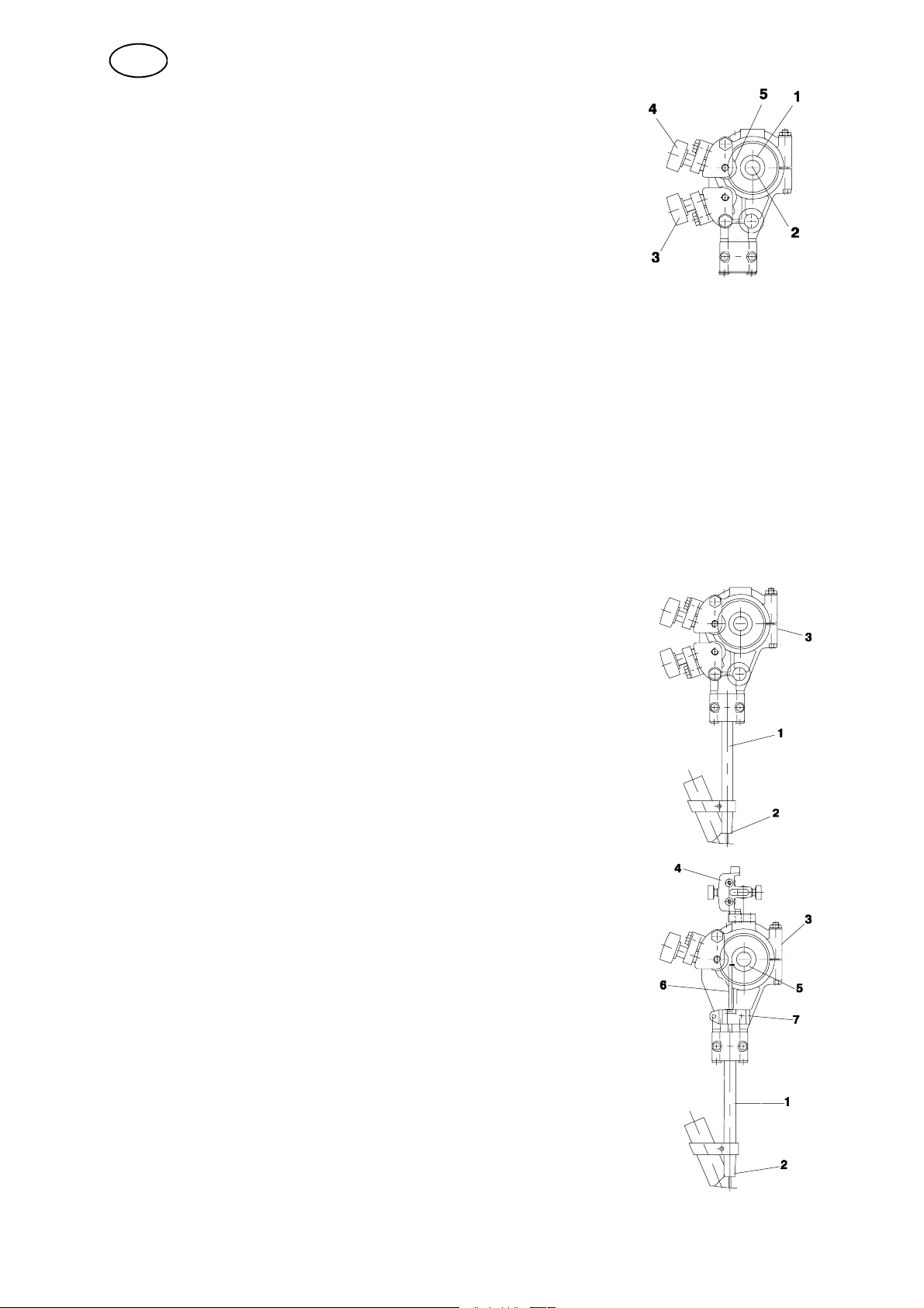
Changing the feed roller
S Single wire
S Release the knobs (3) and (4).
S Release the hand wheel (2).
S Change the feed roller (1). They are marked with their
respective wire sizes.
S Twin wire (Twin--arc)
S Change the feed roller (1) with twin grooves in the same way as
for single wire.
S NOTE! The pressure roller (5) must also be changed. A special curved
pressure roller for twin wire replaces the standard pressure roller for single
wire.
S Assemble the pressure roller with special stub shaft
(order no. 146 253--001).
S Flux--cored wire (for knurled rollers)
S Change the feed roller (1) and pressure roller (5) as a pair for the wire size
to be used.
NOTE! A special stub shaft is required for the pressure roller
(order no. 2129 011--01).
S Tighten the pressure screw (4) with moderate pressure to ensure that the
flux-- cored wire does not deform.
Contact equipment for submerged--arc welding
S For single wire 3.0 -- 4.0 mm. Light duty (D20)
Use the straightener (3), connector (1) D20 with contact tip
(2) (M12 thread).
S Tighten the contact tip (2) with a key in order to ensure
that a good contact is achieved.
S For single wire 1.6 -- 2.5 mm Submerged--arc.
Light duty (D20)
Use the straightener (3), connector (1) D20 with contact
tip (2) (M12 thread) and separate fine wire straightener (4)
with guide tube (6).
S Assemble the clamp (7) with guide tube (6) in the M12
hole on the straightener (3). The guide tube (6) should
bottom on the contact tip (2).
S If necessary, cut the guide tube (6) to length so that the
feed roller (5) runs freely.
S Assemble the fine wire straightener (4) on the upper
side of the clamp for the straightener (3).
ffa8o1ea
-- 8 4 --
Page 17
GB
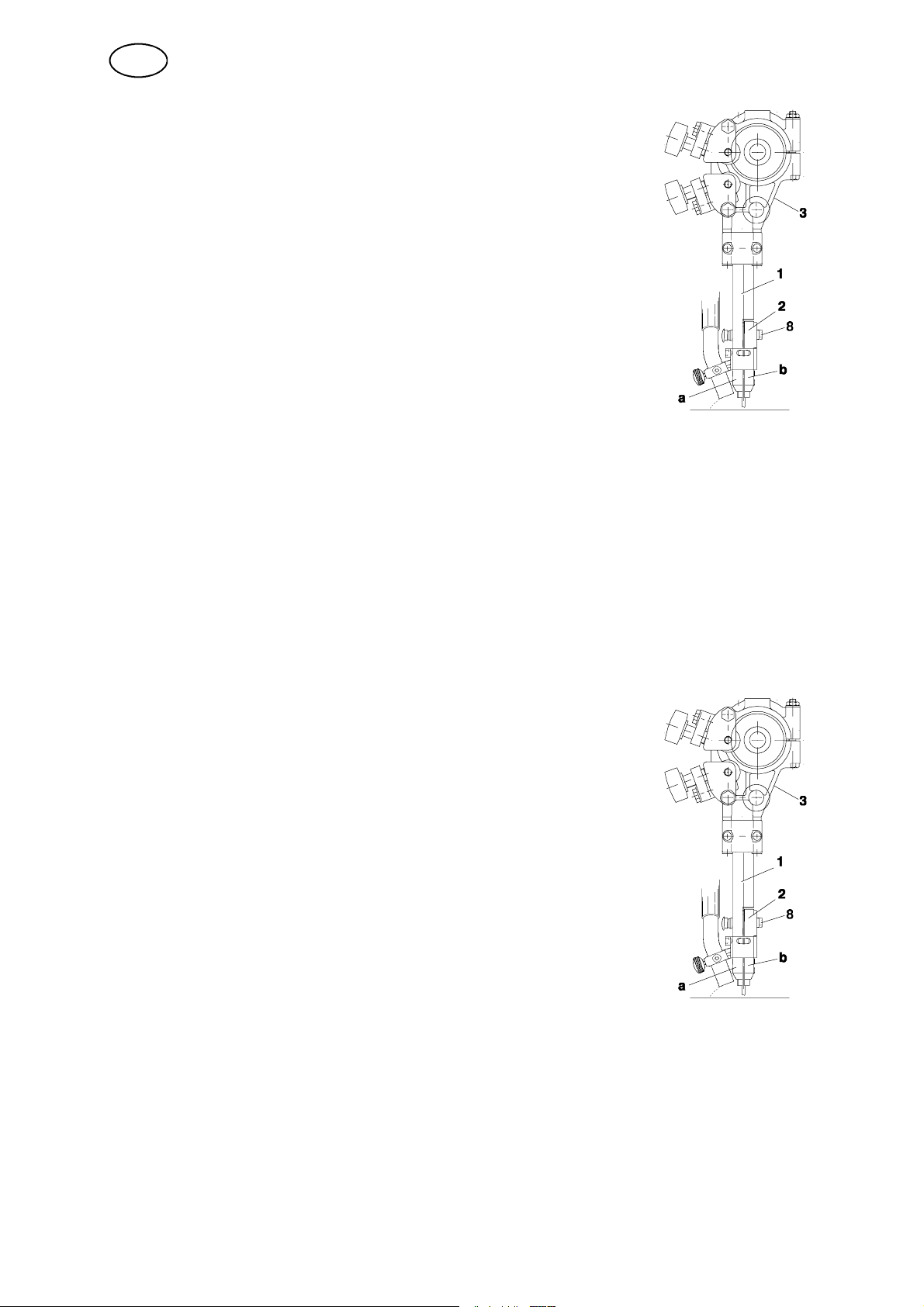
S For single wire 3.0 -- 6.0 mm. Heavy duty (D35)
Use the straightener (3), connector (1) D35 with contact
jaws (2).
S Assemble one contact jaw with the M5 bolts provided, in
the fixed contact tip (a).
S Assemble the other contact jaw in the free half of the
two--piece connector (b) under the bolt (8) and tighten
down hard to ensure that a good contact is achieved
between the contact jaws and the wire.
S For flux--cored wire 1.6 mm -- 4.0 mm (D20 and D35) (Accessories)
If contact jaws (D35) are used, the contact jaws must not be tightened down to
hard in order to ensure that the flux--cored wire is not distorted. Ensure that good
contact is a chieved with the wire.
S Adjustment of the wire for tandem welding
S The distance between the first and second wires must not be so great that
the slag has time to solidify between the wires.
S Ensure that good flux coverage is achieved between the first and second
wires.
S Fortwinwires2x2.0--3.0Heavy Twin (D35) (Accessories)
Use the straightener (3), connector (1) D35 with contact
jaws (2).
S Assemble the first contact jaw with the M5 bolts
supplied, in the fixed connector ( a).
S Assemble the other contact jaw in the free half of the
two--piece connector (b) under the bolt (8) and tighten
down hard to ensure that a good contact is achieved
between the contact jaws and the wire.
ffa8o1ea
-- 8 5 --
Page 18
GB
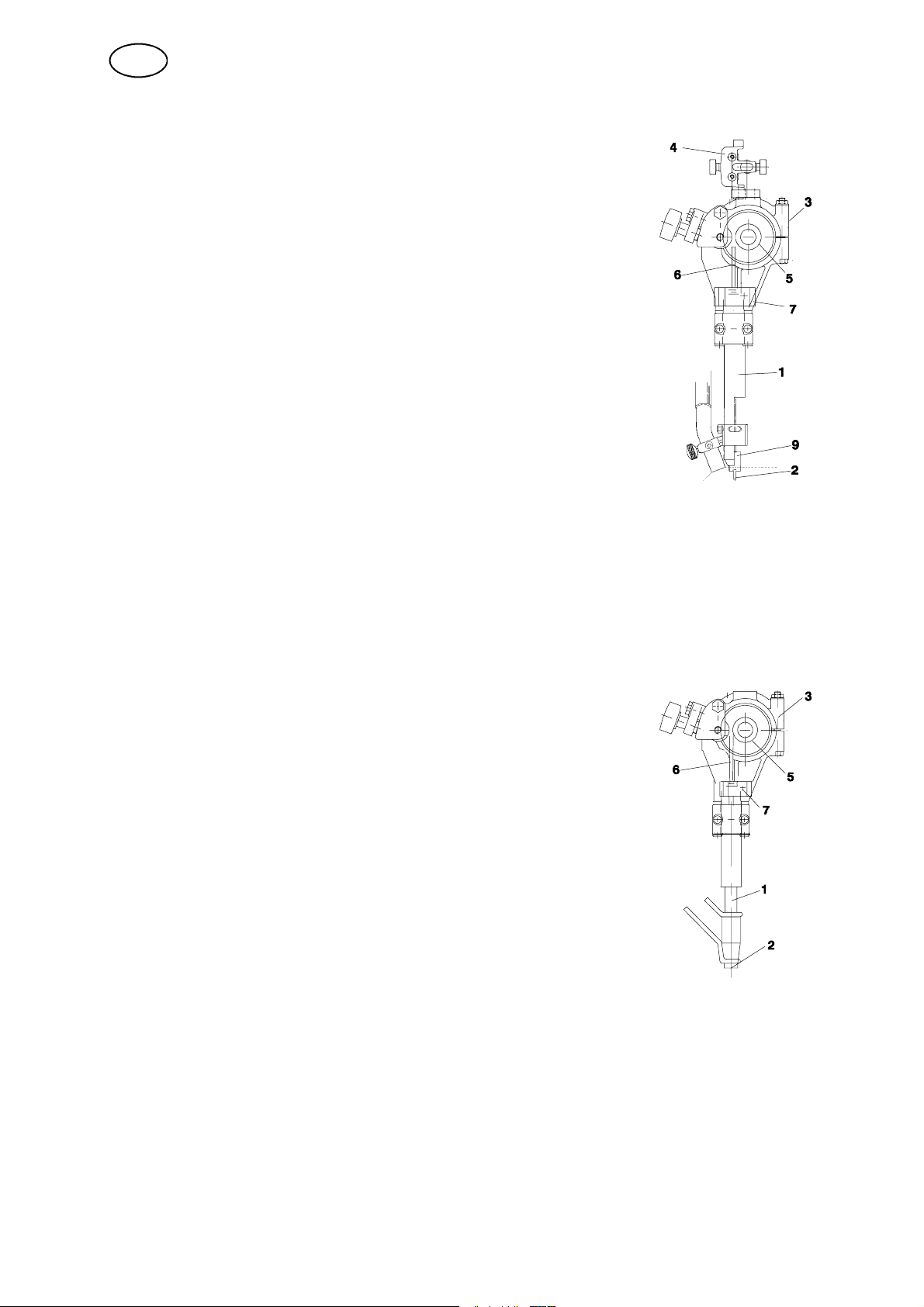
S Fortwinwires2x1.2--2.0mm,LightTwin(D35)(Accessories)
Use the straightener (3), connector (1) D35 with twin adapter
(9) and 2 contact tips (2) (M6 threads) and separate fine wire
straightener (4) with two guide tubes (6). For twin wires < 1.6
mm, a guide spiral, inserted into each guide tube, is used.
S Assemble the twin adapter (9) for M6 contact tips (2) with
the M5 bolts in the fixed half of the two --piece connector
(1).
S Assemble the clamp (7) with guide tube (6) in the M12
hole on the standard straightener (3). The guide tube
should bottom on the twin adapter (9) for the contact tip
(2).
S Tighten the contact tip (2) with a key to ensure that a good
contact is achieved.
S If necessary, cut the guide tube (6) to length so that the
feed roller (5) runs freely.
S Adjustment of the wires for Twin--arc welding:
S Position the wires in the joint so as to achieve optimal weld quality by
rotating the connector. The two wires can be rotated so that they are
positioned one after the other along the line of the joint, or in any position
up to 90¡ across the joint, i.e. one wire on each side of the joint.
Contact equipment for MIG/MAG welding.
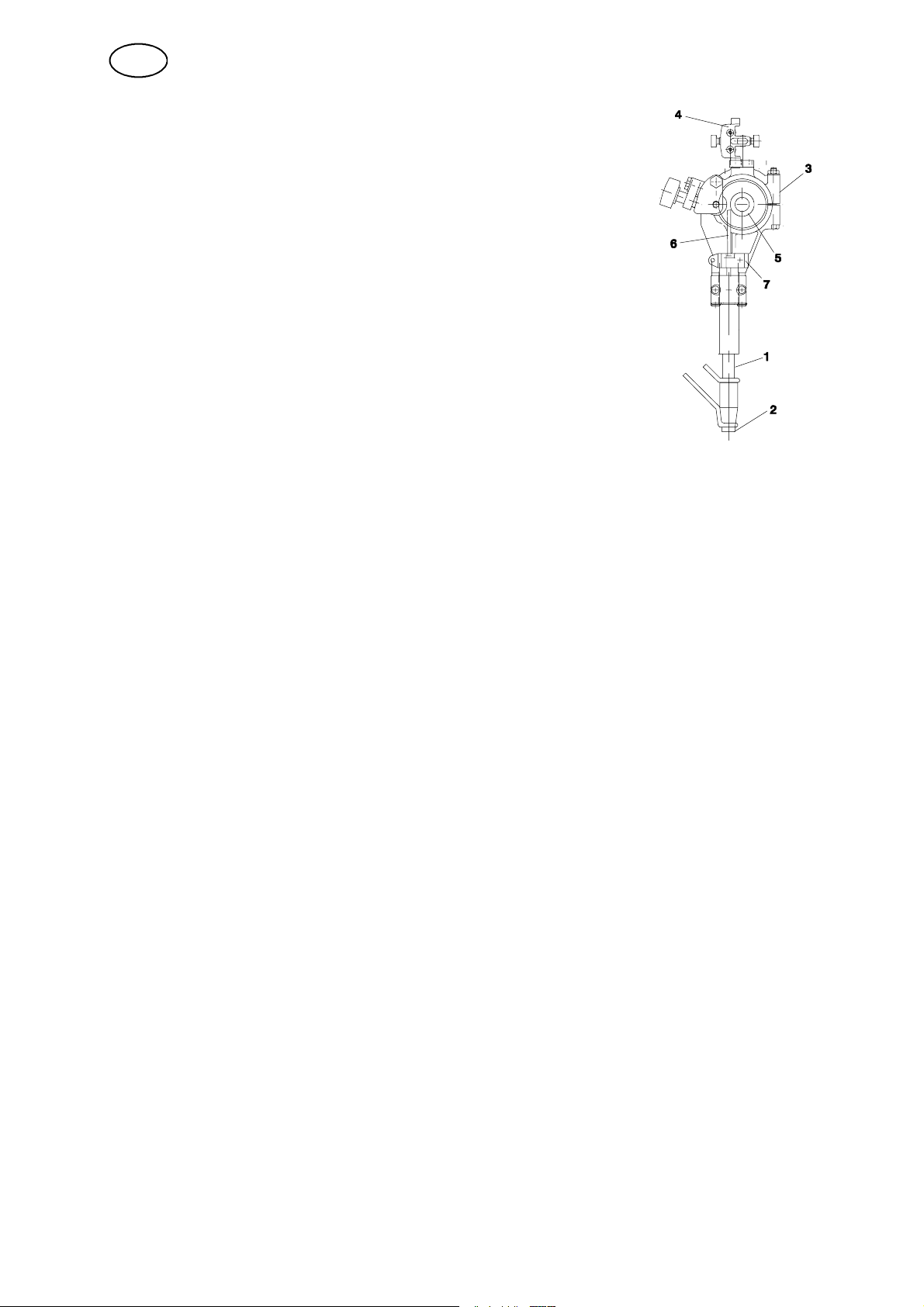
S For single wire 1.6 -- 2.5 mm (D35)
Use the straightener (3), connector (1) D35 with contact
tip (2) (M10 thread).
S Tighten the contact tip (2) with a key to ensure that a
good contact is achieved.
S Assemble the clamp (7) with guide tube (6) in the M12
hole on the standard straightener (3). The guide tube (6)
should bottom on the contact tip (2).
S If necessary, cut the guide tube (6) to length so that the
feed roller (5) runs freely.
ffa8o1ea
-- 8 6 --
Page 19
GB
S For single wire < 1.6 mm (D35)
Use the straightener (3), connector (1) D35 with contact tip
(2) (M12 thread), fine wire straightener (4) with guide tube
(6) and guide spiral, which is inserted in the guide tube (6).
S Assemble the clamp (7) with guide tube (6) in the M12
hole on the standard straightener (3). The guide tube (6)
should bottom on the contact tip (2).
S If necessary, cut the guide tube (6) to length so that the
feed roller (5) runs freely.
S Assemble the fine wire straightener (4) on the upper side
of the clamp for the straightener (3).
S Connect the cooling water and gas (MIG/MAG welding).
4.3 Refilling with flux powder (submerged--arc welding)
S Close the flux valve on the flux hopper.
S Remove the cyclone on the flux recovery unit, if fitted.
S Fill with flux powder. NOTE! The flux powder must be dry. Where possible
avoid using agglomerating flux powder outdoors and in damp environments.
S Position the flux tube so that it does not become kinked.
S Adjust the height of the flux nozzle above the weld so that the correct
amount of flux is delivered.
Flux coverage should be sufficient so that penetration of the arc does not
occur.
4.4 Conversion of A6 TFE1 (Submerged--arc welding) to MIG/MAG
welding
Assemble in accordance with the instructions accompanying the conversion
kit.
4.5 Conversion of A6 TFE1 / A6 SFE2 (Submerged--arc welding) to
Twin--arc
ffa8o1ea
Assemble in accordance with the instructions accompanying the conversion
kit.
-- 8 7 --
Page 20
GB
5 MAINTENANCE
5.1 General
NB! Before doing any kind of maintenance work, make sure the mains is
disconnected.
For the maintenance of the A2-- A6 Process Controller (PEH), see the instruction
manual.
5.2 Daily
S Clean flux and dirt off moving parts of the welding machine.
S Check that the contact tip and all electrical cables are connected.
S Check that all bolted joints are tight and that guides and drive rollers are not
worn or damaged.
S Check the brake hub braking torque. It should not be so low, that the wire reel
continues to rotate when wire feed is stopped and it should not be so great that
the feed rollers slip. As a guide, the braking torque for a 30 kg wire reel should
be 1,5 Nm.
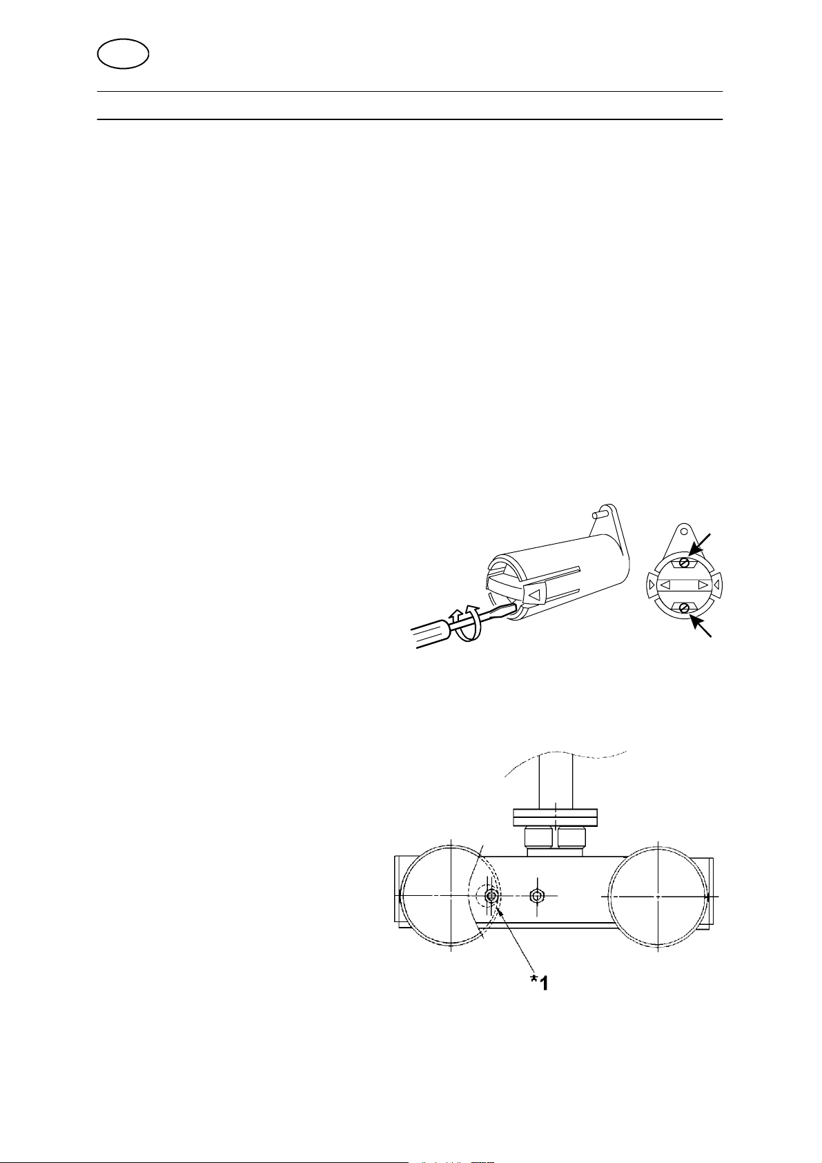
Adjusting the braking torque:
S Turn the red handle to the locked
position.
S Insert a screwdriver into the
springs in the hub.
Turn the springs clockwise to
reduce the braking torque
Turn the springs anticlockwise to increase the braking torque.
NB: Turn both springs through the same amount.
5.3 Regularly
S Check the wire feed motor brushes
once every three months.
Replace when they are worn
downto6mm.
S Eximine the slides and lubricate if
they bind.
S Inspect the wire guides, drive
rollers and contact tip on the wire
feed unit. Replace any worn or damaged
components, (see spare parts list o n page 215).
S If the carriage travel becomes
jerky, check that hte chain is correctly tensioned. Tension the chain if necessary.
S To tension the chain undo the nut (*1) and turn the cam, then tighten the nut.
ffa8u1ea
-- 8 8 --
Page 21

GB
6 TROUBLESHOOTING
6.1 General
Equipment
S Instruction manual for control box A2--A6 Process Controller.
S Operating manual for motor with gear A6 VEC, best nr 443 393.
Check
S that the power supply is connected for the correct mains supply
S that all three phases are supplying the correct voltage (phase sequence is not
important)
S that welding cables and connections are not damaged
S that the controls are correctly set
S that the mains supply is disconnected before starting repairs
6.2 Possible faults
1. Symptom Current and voltage readings show large fluctuations.
Cause 1 .1 Contact jaws or nozzle are worn or wrong size.
Action Replace contact jaws or nozzle.
Cause 1 .2 Feed roller pressure is inadequate.
Action Increase pressure on feed rollers.
2. Symptom Wire feed is irregular.
Cause 2 .1 Pressure on feed rollers incorrectly set.
Action Pressure on feed rollers incorrectly set.
Cause 2 .2 Feed rollers wrong size.
Action Replace feed rollers.
Cause 2 .3 Grooves in feed rollers are worn.
Action Replace feed rollers.
3. Symptom Welding cables overheating.
Cause 3 .1 Poor electrical connection.
Action Clean and tighten all electrical connections.
Cause 3 .2 Cross--sectional area of welding cables too small.
Action Use cables with a larger cross--section or use parallel cables.
7 ORDERING OF SPARE PARTS
Spare parts are ordered through your nearest ESAB representative, see back cover.
When ordering spare parts, please state machine type and number as well as designation and spare part number as shown in the spare parts list on page 215.
This will simplify dispatch and ensure you get the right part.
ffa8f1ea
-- 8 9 --
Page 22
ESAB subsidiaries and representative offices
Europe
AUSTRIA
ESAB Ges.m.b.H
Vienna--Liesing
Tel: +43 1 888 25 11
Fax: +43 1 888 25 11 85
BELGIUM
S.A. ESAB N.V .
Brussels
Tel: +32 2 745 11 00
Fax: +32 2 726 80 05
THE CZECH REPUBLIC
ESAB VAMBERK s.r.o.
Prague
Tel: +420 2 819 40 885
Fax: +420 2 819 40 120
DENMARK
Aktieselskabet ESAB
Copenhagen--Valby
Tel:+4536300111
Fax:+4536304003
FINLAND
ESAB Oy
Helsinki
Tel: +358 9 547 761
Fax: +358 9 547 77 71
FRANCE
ESAB France S.A.
Cergy Pontoise
Tel:+33130755500
Fax:+33130755524
GERMANY
ESAB GmbH
Solingen
Tel: +49 212 298 0
Fax: +49 212 298 204
GREAT BRITAIN
ESAB Group (UK) Ltd
Waltham Cross
Tel: +44 1992 76 85 15
Fax: +44 1992 71 58 03
ESAB Automation Ltd
Andover
Tel: +44 1264 33 22 33
Fax: +44 1264 33 20 74
HUNGARY
ESAB Kft
Budapest
Tel:+3612044182
Fax:+3612044186
ITALY
ESAB Saldatura S.p.A.
Mesero (Mi)
Tel:+3902979681
Fax:+390297289181
THE NETHERLANDS
ESAB Nederland B.V.
Utrecht
Tel: +31 30 248 59 22
Fax: +31 30 248 52 60
NORWAY
AS ESAB
Larvik
Tel:+4733121000
Fax:+4733115203
POLAND
ESAB Sp.z.o.o
Warszaw
Tel: +48 22 813 99 63
Fax: +48 22 813 98 81
PORTUGAL
ESAB Lda
Lisbon
Tel: +351 1 837 1527
Fax: +351 1 859 1277
SLOVAKIA
ESAB Slovakia s.r.o.
Bratislava
Tel:+421744882426
Fax:+421744888741
SPAIN
ESAB Ibérica S.A.
Alcobendas (Madrid)
Tel: +34 91 623 11 00
Fax: +34 91 661 51 83
SWEDEN
ESAB Sverige AB
Gothenburg
Tel:+4631509500
Fax:+4631509222
ESAB International AB
Gothenburg
Tel:+4631509000
Fax:+4631509360
SWITZERLAND
ESAB AG
Dietikon
Tel: +41 1 741 25 25
Fax: +41 1 740 30 55
North and South America
ARGENTINA
CONARCO
Buenos Aires
Tel: +54 11 4 753 4039
Fax: +54 11 4 753 6313
BRAZIL
ESAB S.A.
Contagem--MG
Tel: +55 31 3369 4333
Fax: +55 31 3369 4440
CANADA
ESAB Group Canada Inc.
Missisauga, Ontario
Tel: +1 905 670 02 20
Fax: +1 905 670 48 79
MEXICO
ESAB Mexico S.A.
Monterrey
Tel: +52 8 350 5959
Fax: +52 8 350 7554
USA
ESAB Welding & Cutting Products
Florence, SC
Tel: +1 843 669 44 11
Fax: +1 843 664 44 58
Asia/Pacific
CHINA
Shanghai ESAB A/P
Shanghai
Tel: +86 21 6539 7124
Fax: +86 21 6543 6622
INDIA
ESAB India Ltd
Calcutta
Tel: +91 33 478 45 17
Fax: +91 33 468 18 80
INDONESIA
P.T. Esabindo Pratama
Jakarta
Tel: +62 21 460 01 88
Fax: +62 21 461 29 29
MALAYSIA
ESAB (Malaysia) Snd Bhd
Selangor
Tel: +60 3 703 36 15
Fax: +60 3 703 35 52
SINGAPORE
ESAB Singapore Pte Ltd
Singapore
Tel: +65 861 43 22
Fax: +65 861 31 95
ESAB Asia/Pacific Pte Ltd
Singapore
Tel: +65 861 74 42
Fax: +65 863 08 39
SOUTH KOREA
ESAB SeAH Corporation
Kyung--Nam
Tel: +82 551 289 81 11
Fax: +82 551 289 88 63
UNITED ARAB EMIRATES
ESAB Middle East
Dubai
Tel: +971 4 338 88 29
Fax: +971 4 338 87 29
Representative offices
BULGARIA
ESAB Representative Office
Sofia
Tel/Fax: +359 2 974 42 88
EGYPT
ESAB Egypt
Dokki--Cairo
Tel: +20 2 390 96 69
Fax: +20 2 393 32 13
ROMANIA
ESAB Representative Office
Bucharest
Tel/Fax: +40 1 322 36 74
RUSSIA--CIS
ESAB Representative Office
Moscow
Tel:+70959379820
Fax: +7 095 937 95 80
ESAB Representative Office
St Petersburg
Tel:+78123254362
Fax: +7 812 325 66 85
Distributors
For addresses and phone
numbers to our distributors in
other countries, please visit our
home page
www.esab.com
ESAB AB
SE--695 81 LAXÅ
SWEDEN
Phone +46 584 81 000
www.esab.com
031021
 Loading...