


Precision Plasmarc
Plasma Gas Box & Shield Gas Box
Plasma Gas Box
Shield Gas Box
Instruction Manual
0558005487 10 / 2008

BE SURE THIS INFORMATION REACHES THE OPERATOR.
YOU CAN GET EXTRA COPIES THROUGH YOUR SUPPLIER.
CAUTION
These INSTRUCTIONS are for experienced operators. If you are not fully familiar with the
principles of operation and safe practices for arc welding and cutting equipment, we urge
you to read our booklet, “Precautions and Safe Practices for Arc Welding, Cutting, and
Gouging,” Form 52-529. Do NOT permit untrained persons to install, operate, or maintain
this equipment. Do NOT attempt to install or operate this equipment until you have read
and fully understand these instructions. If you do not fully understand these instructions,
contact your supplier for further information. Be sure to read the Safety Precautions before installing or operating this equipment.
USER RESPONSIBILITY
This equipment will perform in conformity with the description thereof contained in this manual and accompanying labels and/or inserts when installed, operated, maintained and repaired in accordance with the instructions provided. This equipment must be checked periodically. Malfunctioning or poorly maintained equipment
should not be used. Parts that are broken, missing, worn, distorted or contaminated should be replaced immediately. Should such repair or replacement become necessary, the manufacturer recommends that a telephone
or written request for service advice be made to the Authorized Distributor from whom it was purchased.
This equipment or any of its parts should not be altered without the prior written approval of the manufacturer.
The user of this equipment shall have the sole responsibility for any malfunction which results from improper
use, faulty maintenance, damage, improper repair or alteration by anyone other than the manufacturer or a service facility designated by the manufacturer.
READ AND UNDERSTAND THE INSTRUCTION MANUAL BEFORE INSTALLING OR OPERATING.
PROTECT YOURSELF AND OTHERS!

TABLE OF CONTENTS
Section / Title Page
1.0 Safety Precautions ....................................................................................5
1.1 Safety - English ..................................................................................5
1.2 Safety - Spanish .................................................................................9
1.3 Safety - French .................................................................................13
2.0 Description ..........................................................................................17
2.1 System Introduction ............................................................................17
2.2 m3 Plasma System Plasma Gas Box, Shield Gas Box and PT-36 ....................................17
2.3 System Gas Requirements.......................................................................18
2.4 Plasma Gas Box Water Supply Requirements .....................................................18
2.5 Plasma Gas Box Electrical Input Requirements ...................................................18
2.6 Shield Gas Box Electrical Input Requirements ....................................................18
2.7 System Accessories .............................................................................18
2.8 Plasma Gas Box Dimensions.....................................................................19
2.9 Shield Gas Box Dimensions..................................................................... 20
3.0 Installation...........................................................................................21
3.1 Plasma Gas Box Introduction ....................................................................21
3.2 Plasma Gas Box Mounting (Bottom View)........................................................21
3.3 Plasma Gas Box Connections ...................................................................22
3.4 Plasma Gas Box Nomex Insulation ............................................................. 28
3.5 Plasma Gas Box Gas Connections............................................................... 29
3.6 Shield Gas Box Introduction .....................................................................31
3.7 Shield Gas Box Mounting (Bottom View).........................................................31
3.8 Shield Gas Box Connections.....................................................................32
3.9 Component Relationship Block Diagram........................................................ 34
4.0 Operation ...........................................................................................41
4.1 Plasma Gas Box Operation ......................................................................41
4.2 Plasma Gas Box Pressure Gauges ................................................................41
4.3 Plasma Gas Box Pressure Switches ...............................................................42
4.4 Shield Gas Box Operation ...................................................................... 43
4.5 Shield Gas Box Air Regulator for Air Curtain ..................................................... 44
4.6 Shield Gas Box Check Valves ................................................................... 45

TABLE OF CONTENTS
5.0 Maintenance........................................................................................47
5.1 Plasma Gas Box Maintenance ..................................................................47
5.2 Plasma Gas Box Schematic (Plumbing Schematic) ...............................................47
5.3 Plasma Gas Box Pressure Switches..............................................................48
5.4 Spark Gap Of the Arc Starter Box (Plasma Gas Box) ..............................................49
5.5 Spark Adjustment Procedure (Plasma Gas Box)..................................................50
5.6 Cooling Water Circuit (Plasma Gas Box) .........................................................51
5.7 Plasma Gas Schematic .........................................................................52
5.8 Voltage Divider Adjustment Procedure .........................................................53
5.9 Voltage Divider Schematic .....................................................................54
5.10 Shield Gas Box Maintenance ...................................................................55
5.11 Shield Gas Box Schematic......................................................................55
5.12 Solenoid Replacement .........................................................................56
5.13 Mass Flow Controller Replacement .............................................................57
5.14 Gas Filters .....................................................................................58
5.15 Fluid Schematic – m3 Plasma System Plasma Gas Box and Shield Gas Box ........................60
6.0 Replacement Parts ..................................................................................63
6.1 General .......................................................................................63
6.2 Ordering ......................................................................................63
6.3 Plasma Gas Box ................................................................................64
6.4 Start Gas Manifold (Plasma Gas Box)............................................................71
6.5 Buss Bar Manifold (Plasma Gas Box).............................................................73
6.6 Shield Gas Box.................................................................................75
6.7 Shield Gas Manifold (Shield Gas Box) ...........................................................83
4

SECTION 1 SAFETY PRECAUTIONS
1.0 Safety Precautions
WARNING: These Safety Precautions are
for your protection. They summarize precautionary information from the references
listed in Additional Safety Information section. Before performing any installation or operating
procedures, be sure to read and follow the safety precautions listed below as well as all other manuals, material
safety data sheets, labels, etc. Failure to observe Safety
Precautions can result in injury or death.
PROTECT YOURSELF AND OTHERS -Some welding, cutting, and gouging
processes are noisy and require ear
protection. The arc, like the sun, emits
ultraviolet (UV) and other radiation
and can injure skin and eyes. Hot metal can cause
burns. Training in the proper use of the processes
and equipment is essential to prevent accidents.
Therefore:
1. Always wear safety glasses with side shields in any
work area, even if welding helmets, face shields, and
goggles are also required.
2. Use a face shield tted with the correct lter and
cover plates to protect your eyes, face, neck, and
ears from sparks and rays of the arc when operating
or observing operations. Warn bystanders not to
watch the arc and not to expose themselves to the
rays of the electric-arc or hot metal.
3. Wear ameproof gauntlet type gloves, heavy long-
sleeve shirt, cuess trousers, high-topped shoes,
and a welding helmet or cap for hair protection, to
protect against arc rays and hot sparks or hot metal.
A ameproof apron may also be desirable as protection against radiated heat and sparks.
4. Hot sparks or metal can lodge in rolled up sleeves,
trouser cus, or pockets. Sleeves and collars should
be kept buttoned, and open pockets eliminated from
the front of clothing.
5. Protect other personnel from arc rays and hot
sparks with a suitable non-ammable partition or
curtains.
6. Use goggles over safety glasses when chipping slag
or grinding. Chipped slag may be hot and can y far.
Bystanders should also wear goggles over safety
glasses.
1.1 Safety - English
FIRES AND EXPLOSIONS -- Heat from
ames and arcs can start res. Hot
slag or sparks can also cause res and
explosions. Therefore:
1. Remove all combustible materials well away from
the work area or cover the materials with a protective non-ammable covering. Combustible materials
include wood, cloth, sawdust, liquid and gas fuels,
solvents, paints and coatings, paper, etc.
2. Hot sparks or hot metal can fall through cracks or
crevices in oors or wall openings and cause a hidden smoldering re or res on the oor below. Make
certain that such openings are protected from hot
sparks and metal.“
3. Do not weld, cut or perform other hot work until the
workpiece has been completely cleaned so that there
are no substances on the workpiece which might
produce ammable or toxic vapors. Do not do hot
work on closed containers. They may explode.
4. Have re extinguishing equipment handy for instant
use, such as a garden hose, water pail, sand bucket,
or portable re extinguisher. Be sure you are trained
in its use.
5. Do not use equipment beyond its ratings. For example, overloaded welding cable can overheat and
create a re hazard.
6. After completing operations, inspect the work area
to make certain there are no hot sparks or hot metal
which could cause a later re. Use re watchers when
necessary.
7. For additional information, refer to NFPA Standard
51B, "Fire Prevention in Use of Cutting and Welding
Processes", available from the National Fire Protection Association, Batterymarch Park, Quincy, MA
02269.
ELECTRICAL SHOCK -- Contact with
live electrical parts and ground can
cause severe injury or death. DO NOT
use AC welding current in damp areas,
if movement is conned, or if there is
danger of falling.
5

SECTION 1 SAFETY PRECAUTIONS
1. Be sure the power source frame (chassis) is connected to the ground system of the input power.
2. Connect the workpiece to a good electrical
ground.
3. Connect the work cable to the workpiece. A poor
or missing connection can expose you or others
to a fatal shock.
4. Use well-maintained equipment. Replace worn or
damaged cables.
5. Keep everything dry, including clothing, work
area, cables, torch/electrode holder, and power
source.
6. Make sure that all parts of your body are insulated
from work and from ground.
7. Do not stand directly on metal or the earth while
working in tight quarters or a damp area; stand
on dry boards or an insulating platform and wear
rubber-soled shoes.
8. Put on dry, hole-free gloves before turning on the
power.
3. Welders should use the following procedures to
minimize exposure to EMF:
A. Route the electrode and work cables together.
Secure them with tape when possible.
B. Never coil the torch or work cable around your
body.
C. Do not place your body between the torch and
work cables. Route cables on the same side of
your body.
D. Connect the work cable to the workpiece as close
as possible to the area being welded.
E. Keep welding power source and cables as far
away from your body as possible.
FUMES AND GASES -- Fumes and
gases, can cause discomfort or harm,
particularly in conned spaces. Do
not breathe fumes and gases. Shielding gases can cause asphyxiation.
Therefore:
9. Turn o the power before removing your gloves.
10. Refer to ANSI/ASC Standard Z49.1 (listed on
next page) for specic grounding recommendations. Do not mistake the work lead for a ground
cable.
ELECTRIC AND MAGNETIC FIELDS
— May be dangerous. Electric current owing through any conductor causes localized Electric and
Magnetic Fields (EMF). Welding and
cutting current creates EMF around welding cables
and welding machines. Therefore:
1. Welders having pacemakers should consult their
physician before welding. EMF may interfere with
some pacemakers.
2. Exposure to EMF may have other health eects which
are unknown.
1. Always provide adequate ventilation in the work area
by natural or mechanical means. Do not weld, cut, or
gouge on materials such as galvanized steel, stainless steel, copper, zinc, lead, beryllium, or cadmium
unless positive mechanical ventilation is provided.
Do not breathe fumes from these materials.
2. Do not operate near degreasing and spraying operations. The heat or arc rays can react with chlorinated
hydrocarbon vapors to form phosgene, a highly
toxic gas, and other irritant gases.
3. If you develop momentary eye, nose, or throat irritation while operating, this is an indication that
ventilation is not adequate. Stop work and take
necessary steps to improve ventilation in the work
area. Do not continue to operate if physical discomfort persists.
4. Refer to ANSI/ASC Standard Z49.1 (see listing below)
for specic ventilation recommendations.
6

SECTION 1 SAFETY PRECAUTIONS
5. WARNING: This product, when used for welding
or cutting, produces fumes or gases
which contain chemicals known to
the State of California to cause birth
defects and, in some cases, cancer.
(California Health & Safety Code
§25249.5 et seq.)
CYLINDER HANDLING -- Cylinders,
if mishandled, can rupture and violently release gas. Sudden rupture
of cylinder, valve, or relief device can
injure or kill. Therefore:
1. Use the proper gas for the process and use the
proper pressure reducing regulator designed to
operate from the compressed gas cylinder. Do not
use adaptors. Maintain hoses and ttings in good
condition. Follow manufacturer's operating instructions for mounting regulator to a compressed gas
cylinder.
1. Always have qualied personnel perform the installation, troubleshooting, and maintenance work.
Do not perform any electrical work unless you are
qualied to perform such work.
2. Before performing any maintenance work inside a
power source, disconnect the power source from
the incoming electrical power.
3. Maintain cables, grounding wire, connections, power
cord, and power supply in safe working order. Do
not operate any equipment in faulty condition.
4. Do not abuse any equipment or accessories. Keep
equipment away from heat sources such as furnaces,
wet conditions such as water puddles, oil or grease,
corrosive atmospheres and inclement weather.
5. Keep all safety devices and cabinet covers in position
and in good repair.
6. Use equipment only for its intended purpose. Do
not modify it in any manner.
2. Always secure cylinders in an upright position by
chain or strap to suitable hand trucks, undercarriages, benches, walls, post, or racks. Never secure
cylinders to work tables or xtures where they may
become part of an electrical circuit.
3. When not in use, keep cylinder valves closed. Have
valve protection cap in place if regulator is not connected. Secure and move cylinders by using suitable
hand trucks. Avoid rough handling of cylinders.
4. Locate cylinders away from heat, sparks, and ames.
Never strike an arc on a cylinder.
5. For additional information, refer to CGA Standard P-1,
"Precautions for Safe Handling of Compressed Gases
in Cylinders", which is available from Compressed
Gas Association, 1235 Jeerson Davis Highway,
Arlington, VA 22202.
EQUIPMENT MAINTENANCE -- Faulty or
improperly maintained equipment can
cause injury or death. Therefore:
ADDITIONAL SAFETY INFORMATION -- For
more information on safe practices for
electric arc welding and cutting equipment, ask your supplier for a copy of
"Precautions and Safe Practices for Arc
Welding, Cutting and Gouging", Form
52-529.
The following publications, which are available from
the American Welding Society, 550 N.W. LeJuene Road,
Miami, FL 33126, are recommended to you:
1. ANSI/ASC Z49.1 - "Safety in Welding and Cutting"
2. AWS C5.1 - "Recommended Practices for Plasma Arc
Welding"
3. AWS C5.2 - "Recommended Practices for Plasma Arc
Cutting"
4. AWS C5.3 - "Recommended Practices for Air Carbon
Arc Gouging and Cutting"
7

SECTION 1 SAFETY PRECAUTIONS
5. AWS C5.5 - "Recommended Practices for Gas Tungsten Arc Welding“
6. AWS C5.6 - "Recommended Practices for Gas Metal
Arc Welding"“
7. AWS SP - "Safe Practices" - Reprint, Welding Handbook.
8. ANSI/AWS F4.1, "Recommended Safe Practices for
Welding and Cutting of Containers That Have Held
Hazardous Substances."
MEANING OF SYMBOLS - As used
throughout this manual: Means Attention! Be Alert! Your safety is involved.
Means immediate hazards which,
if not avoided, will result in immediate, serious personal injury
or loss of life.
Means potential hazards which
could result in personal injury or
loss of life.
Means hazards which could result
in minor personal injury.
8

SECTION 1 SEGURIDAD
1.2 Safety - Spanish
ADVERTENCIA: Estas Precauciones de Se-
guridad son para su protección. Ellas hacen
resumen de información proveniente de las
referencias listadas en la sección "Información Adicional Sobre La Seguridad". Antes de hacer cualquier
instalación o procedimiento de operación , asegúrese
de leer y seguir las precauciones de seguridad listadas
a continuación así como también todo manual, hoja
de datos de seguridad del material, calcomanias, etc.
El no observar las Precauciones de Seguridad puede
resultar en daño a la persona o muerte.
PROTEJASE USTED Y A LOS DEMAS-Algunos procesos de soldadura, corte
y ranurado son ruidosos y requiren
protección para los oídos. El arco,
como el sol , emite rayos ultravioleta
(UV) y otras radiaciones que pueden dañar la piel
y los ojos. El metal caliente causa quemaduras. EL
entrenamiento en el uso propio de los equipos y
sus procesos es esencial para prevenir accidentes.
Por lo tanto:
1. Utilice gafas de seguridad con protección a los lados
siempre que esté en el área de trabajo, aún cuando
esté usando careta de soldar, protector para su cara
u otro tipo de protección.
2. Use una careta que tenga el ltro correcto y lente
para proteger sus ojos, cara, cuello, y oídos de las
chispas y rayos del arco cuando se esté operando y
observando las operaciones. Alerte a todas las personas cercanas de no mirar el arco y no exponerse
a los rayos del arco eléctrico o el metal fundido.
3. Use guantes de cuero a prueba de fuego, camisa
pesada de mangas largas, pantalón de ruedo liso,
zapato alto al tobillo, y careta de soldar con capucha
para el pelo, para proteger el cuerpo de los rayos y
chispas calientes provenientes del metal fundido.
En ocaciones un delantal a prueba de fuego es
necesario para protegerse del calor radiado y las
chispas.
4. Chispas y partículas de metal caliente puede alojarse
en las mangas enrolladas de la camisa , el ruedo del
pantalón o los bolsillos. Mangas y cuellos deberán
mantenerse abotonados, bolsillos al frente de la
camisa deberán ser cerrados o eliminados.
5. Proteja a otras personas de los rayos del arco y chis-
pas calientes con una cortina adecuada no-amable
como división.
6. Use careta protectora además de sus gafas de segu-
ridad cuando esté removiendo escoria o puliendo.
La escoria puede estar caliente y dEPPrenderse con
velocidad. Personas cercanas deberán usar gafas
de seguridad y careta protectora.
FUEGO Y EXPLOSIONES -- El calor de
las amas y el arco pueden ocacionar
fuegos. Escoria caliente y las chispas
pueden causar fuegos y explosiones.
Por lo tanto:
1. Remueva todo material combustible lejos del área
de trabajo o cubra los materiales con una cobija a
prueba de fuego. Materiales combustibles incluyen
madera, ropa, líquidos y gases amables, solventes,
pinturas, papel, etc.
2. Chispas y partículas de metal pueden introducirse en
las grietas y agujeros de pisos y paredes causando
fuegos escondidos en otros niveles o EPPacios.
Asegúrese de que toda grieta y agujero esté cubierto
para proteger lugares adyacentes contra fuegos.
3. No corte, suelde o haga cualquier otro trabajo
relacionado hasta que la pieza de trabajo esté totalmente limpia y libre de substancias que puedan
producir gases inamables o vapores tóxicos. No
trabaje dentro o fuera de contenedores o tanques
cerrados. Estos pueden explotar si contienen vapores
inamables.
4. Tenga siempre a la mano equipo extintor de fuego para uso instantáneo, como por ejemplo una
manguera con agua, cubeta con agua, cubeta con
arena, o extintor portátil. Asegúrese que usted esta
entrenado para su uso.
5. No use el equipo fuera de su rango de operación. Por
ejemplo, el calor causado por cable sobrecarga en
los cables de soldar pueden ocasionar un fuego.
6. DEPPués de termirar la operación del equipo, inspeccione el área de trabajo para cerciorarse de que las
chispas o metal caliente ocasionen un fuego más
tarde. Tenga personal asignado para vigilar si es
necesario.
7. Para información adicional , haga referencia a la
publicación NFPA Standard 51B, "Fire Prevention in
Use of Cutting and Welding Processes", disponible
a través de la National Fire Protection Association,
Batterymarch Park, Quincy, MA 02269.
CHOQUE ELECTRICO -- El contacto
con las partes eléctricas energizadas
y tierra puede causar daño severo o
muerte. NO use soldadura de corri-
ente alterna (AC) en áreas húmedas,
de movimiento connado en lugares estrechos o
si hay posibilidad de caer al suelo.
9

SECTION 1 SEGURIDAD
1. Asegúrese de que el chasis de la fuente de poder
esté conectado a tierra através del sistema de
electricidad primario.
2. Conecte la pieza de trabajo a un buen sistema de
tierra física.
3. Conecte el cable de retorno a la pieza de trabajo.
Cables y conductores expuestos o con malas
conexiones pueden exponer al operador u otras
personas a un choque eléctrico fatal.
4. Use el equipo solamente si está en buenas condiciones. Reemplaze cables rotos, dañados o con
conductores expuestos.
5. Mantenga todo seco, incluyendo su ropa, el área de
trabajo, los cables, antorchas, pinza del electrodo,
y la fuente de poder.
6. Asegúrese que todas las partes de su cuerpo están
insuladas de ambos, la pieza de trabajo y tierra.
7. No se pare directamente sobre metal o tierra mientras trabaja en lugares estrechos o áreas húmedas;
trabaje sobre un pedazo de madera seco o una
plataforma insulada y use zapatos con suela de
goma.
8. Use guantes secos y sin agujeros antes de energizar
el equipo.
9. Apage el equipo antes de quitarse sus guantes.
10. Use como referencia la publicación ANSI/ASC
Standard Z49.1 (listado en la próxima página) para
recomendaciones EPPecícas de como conectar el
equipo a tierra. No confunda el cable de soldar a
la pieza de trabajo con el cable a tierra.
CAMPOS ELECTRICOS Y MAGNETICOS - Son peligrosos. La corriente
eléctrica uye através de cualquier
conductor causando a nivel local
Campos Eléctricos y Magnéticos
(EMF). Las corrientes en el área de corte y soldadura,
crean EMF alrrededor de los cables de soldar y las
maquinas. Por lo tanto:
1. Soldadores u Operadores que use marca-pasos para
el corazón deberán consultar a su médico antes de
soldar. El Campo Electromagnético (EMF) puede
interferir con algunos marca-pasos.
2. Exponerse a campos electromagnéticos (EMF) puede
causar otros efectos de salud aún desconocidos.
3. Los soldadores deberán usar los siguientes procedimientos para minimizar exponerse al EMF:
A. Mantenga el electrodo y el cable a la pieza de
trabajo juntos, hasta llegar a la pieza que usted
quiere soldar. Asegúrelos uno junto al otro con
cinta adhesiva cuando sea posible.
B. Nunca envuelva los cables de soldar alrededor
de su cuerpo.
C. Nunca ubique su cuerpo entre la antorcha y el
cable, a la pieza de trabajo. Mantega los cables a
un sólo lado de su cuerpo.
D. Conecte el cable de trabajo a la pieza de trabajo
lo más cercano posible al área de la soldadura.
E. Mantenga la fuente de poder y los cables de soldar
lo más lejos posible de su cuerpo.
HUMO Y GASES -- El humo y los
gases, pueden causar malestar o
daño, particularmente en EPPacios
sin ventilación. No inhale el humo
o gases. El gas de protección puede
causar falta de oxígeno.
Por lo tanto:
1. Siempre provea ventilación adecuada en el área
de trabajo por medio natural o mecánico. No solde,
corte, o ranure materiales con hierro galvanizado,
acero inoxidable, cobre, zinc, plomo, berílio, o cadmio a menos que provea ventilación mecánica
positiva . No rEPPire los gases producidos por
estos materiales.
2. No opere cerca de lugares donde se aplique sub-
stancias químicas en aerosol. El calor de los rayos
del arco pueden reaccionar con los vapores de
hidrocarburo clorinado para formar un fosfógeno,
o gas tóxico, y otros irritant es.
3. Si momentáneamente desarrolla inrritación de
ojos, nariz o garganta mientras est á operando, es
indicación de que la ventilación no es apropiada.
Pare de trabajar y tome las medidas necesarias
para mejorar la ventilación en el área de trabajo.
No continúe operando si el malestar físico persiste.
4. Haga referencia a la publicación ANSI/ASC Standard
Z49.1 (Vea la lista a continuación) para recomendaciones EPPecícas en la ventilación.
10

SECTION 1 SEGURIDAD
5. ADVERTENCIA-- Este producto cuando se utiliza para soldaduras o cortes,
produce humos o gases, los
cuales contienen químicos
conocidos por el Estado de California de causar defectos en el
nacimiento, o en algunos casos,
Cancer. (California Health &
Safety Code §25249.5 et seq.)
MANEJO DE CILINDROS-- Los
cilindros, si no son manejados
correctamente, pueden romperse y liberar violentamente
gases. Rotura repentina del
cilindro, válvula, o válvula de
escape puede causar daño o
muerte. Por lo tanto:
1. Utilize el gas apropiado para el proceso y utilize
un regulador diseñado para operar y reducir la
presión del cilindro de gas . No utilice adaptadores. Mantenga las mangueras y las conexiones
en buenas condiciones. Observe las instrucciones
de operación del manufacturero para montar el
regulador en el cilindro de gas comprimido.
2. Asegure siempre los cilindros en posición vertical
y amárrelos con una correa o cadena adecuada
para asegurar el cilindro al carro, transportes, tablilleros, paredes, postes, o armazón. Nunca asegure
los cilindros a la mesa de trabajo o las piezas que
son parte del circuito de soldadura . Este puede ser
parte del circuito elélectrico.
3. Cuando el cilindro no está en uso, mantenga la
válvula del cilindro cerrada. Ponga el capote de
protección sobre la válvula si el regulador no
está conectado. Asegure y mueva los cilindros
utilizando un carro o transporte adecuado. Evite
el manejo brusco de los
1. Siempre tenga personal cualicado para efectuar l a instalación, diagnóstico, y mantenimiento
del equipo. No ejecute ningún trabajo eléctrico a
menos que usted esté cualicado para hacer el
trabajo.
2. Antes de dar mantenimiento en el interior de la
fuente de poder, desconecte la fuente de poder
del suministro de electricidad primaria.
3. Mantenga los cables, cable a tierra, conexciones,
cable primario, y cualquier otra fuente de poder
en buen estado operacional. No opere ningún
equipo en malas condiciones.
4. No abuse del equipo y sus accesorios. Mantenga
el equipo lejos de cosas que generen calor como
hornos, también lugares húmedos como charcos
de agua , aceite o grasa, atmósferas corrosivas y
las inclemencias del tiempo.
5. Mantenga todos los artículos de seguridad y
coverturas del equipo en su posición y en buenas
condiciones.
6. Use el equipo sólo para el propósito que fue
diseñado. No modique el equipo en ninguna
manera.
INFORMACION ADICIONAL DE SEGURIDAD -- Para más información sobre las
prácticas de seguridad de los equipos de
arco eléctrico para soldar y cortar, pregunte
a su suplidor por una copia de "Precautions
and Safe Practices for Arc Welding, Cutting
and Gouging-Form 52-529.
Las siguientes publicaciones, disponibles através de
la American Welding Society, 550 N.W. LeJuene Road,
Miami, FL 33126, son recomendadas para usted:
1. ANSI/ASC Z49.1 - "Safety in Welding and Cutting"
2. AWS C5.1 - "Recommended Practices for Plasma Arc
Welding"
MANTENIMIENTO DEL EQUIPO -- Equipo
defectuoso o mal mantenido puede
causar daño o muerte. Por lo tanto:
3. AWS C5.2 - "Recommended Practices for Plasma Arc
Cutting"
4. AWS C5.3 - "Recommended Practices for Air Carbon
Arc Gouging and Cutting"
11

SECTION 1 SEGURIDAD
SIGNIFICADO DE LOS SIMBOLOS
-- Según usted avanza en la lectura
de este folleto: Los Símbolos Signican ¡Atención! ¡Esté Alerta! Se
trata de su seguridad.
Signica riesgo inmediato que,
de no ser evadido, puede resultar
inmediatamente en serio daño
personal o la muerte.
Signica el riesgo de un peligro
potencial que puede resultar en
serio daño personal o la muerte.
Signica el posible riesgo que
puede resultar en menores daños
a la persona.
12

SECTION 1 SÉCURITÉ
1.3 Safety - French
AVERTISSEMENT : Ces règles de sécurité
ont pour but d'assurer votre protection. Ils
récapitulent les informations de précaution
provenant des références dans la section
des Informations de sécurité supplémentaires. Avant
de procéder à l'installation ou d'utiliser l'unité, assurezvous de lire et de suivre les précautions de sécurité cidessous, dans les manuels, les ches d'information sur la
sécurité du matériel et sur les étiquettes, etc. Tout défaut
d'observer ces précautions de sécurité peut entraîner
des blessures graves ou mortelles.
PROTÉGEZ-VOUS -- Les processus de
soudage, de coupage et de gougeage
produisent un niveau de bruit élevé et
exige l'emploi d'une protection auditive. L'arc, tout
comme le soleil, émet des rayons ultraviolets en plus
d'autre rayons qui peuvent causer des blessures à la
peau et les yeux. Le métal incandescent peut causer
des brûlures. Une formation reliée à l'usage des
processus et de l'équipement est essentielle pour
prévenir les accidents. Par conséquent:
1. Portez des lunettes protectrices munies d'écrans la-
téraux lorsque vous êtes dans l'aire de travail, même
si vous devez porter un casque de soudeur, un écran
facial ou des lunettes étanches.
2. Portez un écran facial muni de verres ltrants et de
plaques protectrices appropriées an de protéger
vos yeux, votre visage, votre cou et vos oreilles des
étincelles et des rayons de l'arc lors d'une opération
ou lorsque vous observez une opération. Avertissez
les personnes se trouvant à proximité de ne pas regarder l'arc et de ne pas s'exposer aux rayons de l'arc
électrique ou le métal incandescent.
3. Portez des gants ignifugiés à crispin, une chemise
épaisse à manches longues, des pantalons sans rebord
et des chaussures montantes an de vous protéger des
rayons de l'arc, des étincelles et du métal incandescent,
en plus d'un casque de soudeur ou casquette pour
protéger vos cheveux. Il est également recommandé
d e p o r t e r u n t a b l i e r i n i n a m m a b l e a n d e v o u s p r o t é ger des étincelles et de la chaleur par rayonnement.
4. Les étincelles et les projections de métal incandescent
risquent de se loger dans les manches retroussées,
les rebords de pantalons ou les poches. Il est recommandé de garder boutonnés le col et les manches et
de porter des vêtements sans poches en avant.
5. Protégez toute personne se trouvant à proximité des
étincelles et des rayons de l'arc à l'aide d'un rideau ou
d'une cloison ininammable.
6. Portez des lunettes étanches par dessus vos lunettes
de sécurité lors des opérations d'écaillage ou de
meulage du laitier. Les écailles de laitier incandescent
peuvent être projetées à des distances considérables.
L es p er so n ne s se tr o uv an t à p ro x im it é do iv e nt ég a le ment porter des lunettes étanches par dessus leur
lunettes de sécurité.
INCENDIES ET EXPLOSIONS -- La
chaleur provenant des ammes ou de
l'arc peut provoquer un incendie. Le
laitier incandescent ou les étincelles
peuvent également provoquer un
incendie ou une explosion. Par conséquent :
1. Éloignez susamment tous les matériaux combustibles de l'aire de travail et recouvrez les matériaux
avec un revêtement protecteur ininammable. Les
matériaux combustibles incluent le bois, les vêtements, la sciure, le gaz et les liquides combustibles,
les solvants, les peintures et les revêtements, le
papier, etc.
2. Les étincelles et les projections de métal incandescent peuvent tomber dans les ssures dans
les planchers ou dans les ouvertures des murs et
déclencher un incendie couvant à l'étage inférieur
Assurez-vous que ces ouvertures sont bien protégées
des étincelles et du métal incandescent.
3. N'exécutez pas de soudure, de coupe ou autre travail à chaud avant d'avoir complètement nettoyé la
surface de la pièce à traiter de façon à ce qu'il n'ait
aucune substance présente qui pourrait produire
des vapeurs inammables ou toxiques. N'exécutez
pas de travail à chaud sur des contenants fermés
car ces derniers pourraient exploser.
4. Assurez-vous qu'un équipement d'extinction
d'incendie est disponible et prêt à servir, tel qu'un
tuyau d'arrosage, un seau d'eau, un seau de sable
ou un extincteur portatif. Assurez-vous d'être bien
instruit par rapport à l'usage de cet équipement.
5. Assurez-vous de ne pas excéder la capacité de
l'équipement. Par exemple, un câble de soudage
surchargé peut surchauer et provoquer un incendie.
6. Une fois les opérations terminées, inspectez l'aire de
travail pour assurer qu'aucune étincelle ou projection de métal incandescent ne risque de provoquer
un incendie ultérieurement. Employez des guetteurs
d'incendie au besoin.
7. Pour obtenir des informations supplémentaires,
consultez le NFPA Standard 51B, "Fire Prevention in
Use of Cutting and Welding Processes", disponible au
National Fire Protection Association, Batterymarch
Park, Quincy, MA 02269.
CHOC ÉLECTRIQUE -- Le contact avec
des pièces électriques ou les pièces
de mise à la terre sous tension peut
causer des blessures graves ou mor-
telles. NE PAS utiliser un courant de
soudage c.a. dans un endroit humide, en EPPace
restreint ou si un danger de chute se pose.
13

SECTION 1 SÉCURITÉ
1. Assurez-vous que le châssis de la source
d'alimentation est branché au système de mise à
la terre de l'alimentation d'entrée.
2. Branchez la pièce à traiter à une bonne mise de
terre électrique.
3. Branchez le câble de masse à la pièce à traiter et
assurez une bonne connexion an d'éviter le risque
de choc électrique mortel.
4. Utilisez toujours un équipement correctement
entretenu. Remplacez les câbles usés ou endommagés.
5. Veillez à garder votre environnement sec, incluant
les vêtements, l'aire de travail, les câbles, le porteélectrode/torche et la source d'alimentation.
6. Assurez-vous que tout votre corps est bien isolé
de la pièce à traiter et des pièces de la mise à la
terre.
7. Si vous devez eectuer votre travail dans un EPPace
restreint ou humide, ne tenez vous pas directement sur le métal ou sur la terre; tenez-vous sur
des planches sèches ou une plate-forme isolée et
portez des chaussures à semelles de caoutchouc.
8. Avant de mettre l'équipement sous tension, isolez
vos mains avec des gants secs et sans trous.
9. Mettez l'équipement hors tension avant d'enlever
vos gants.
10. Consultez ANSI/ASC Standard Z49.1 (listé à
la page suivante) pour des recommandations
spéciques concernant les procédures de mise à
la terre. Ne pas confondre le câble de masse avec
le câble de mise à la terre.
CHAMPS ÉLECTRIQUES ET MAGNÉTIQUES — comportent un risque de
danger. Le courant électrique qui
passe dans n'importe quel conduc-
teur produit des champs électriques
et magnétiques localisés. Le soudage et le courant de coupage créent des champs électriques
et magnétiques autour des câbles de soudage et
l'équipement. Par conséquent :
1. Un soudeur ayant un stimulateur cardiaque doit
consulter son médecin avant d'entreprendre une
opération de soudage. Les champs électriques et
magnétiques peuvent causer des ennuis pour certains stimulateurs cardiaques.
2. L'exposition à des champs électriques et magné-
tiques peut avoir des eets néfastes inconnus pour
la santé.
3. Les soudeurs doivent suivre les procédures suivantes
pour minimiser l'exposition aux champs électriques
et magnétiques :
A. Acheminez l'électrode et les câbles de masse
ensemble. Fixez-les à l'aide d'une bande adhésive
lorsque possible.
B. Ne jamais enrouler la torche ou le câble de masse
autour de votre corps.
C. Ne jamais vous placer entre la torche et les câbles
de masse. Acheminez tous les câbles sur le même
côté de votre corps.
D. Branchez le câble de masse à la pièce à traiter le
plus près possible de la section à souder.
E. Veillez à garder la source d'alimentation pour le
soudage et les câbles à une distance appropriée
de votre corps.
LES VAPEURS ET LES GAZ -- peuvent
causer un malaise ou des dommages
corporels, plus particulièrement
dans les EPPaces restreints. Ne rEPPirez pas les vapeurs et les gaz. Le
gaz de protection risque de causer
l'asphyxie. Par conséquent :
1. Assurez en permanence une ventilation adéquate
dans l'aire de travail en maintenant une ventilation naturelle ou à l'aide de moyens mécanique.
N'effectuez jamais de travaux de soudage, de
coupage ou de gougeage sur des matériaux tels que
l'acier galvanisé, l'acier inoxydable, le cuivre, le zinc,
le plomb, le berylliym ou le cadmium en l'absence
de moyens mécaniques de ventilation ecaces. Ne
rEPPirez pas les vapeurs de ces matériaux.
2. N'eectuez jamais de travaux à proximité d'une
opération de dégraissage ou de pulvérisation. Lorsque la chaleur
ou le rayonnement de l'arc entre en contact avec les
vapeurs d'hydrocarbure chloré, ceci peut déclencher
la formation de phosgène ou d'autres gaz irritants,
tous extrêmement toxiques.
3. Une irritation momentanée des yeux, du nez ou de la
gorge au cours d'une opération indique que la ventilation n'est pas adéquate. Cessez votre travail an
de prendre les mesures nécessaires pour améliorer
la ventilation dans l'aire de travail. Ne poursuivez
pas l'opération si le malaise persiste.
4. Consultez ANSI/ASC Standard Z49.1 (à la page
suivante) pour des recommandations spéciques
concernant la ventilation.
14

SECTION 1 SÉCURITÉ
5. AVERTISSEMENT : Ce produit, lorsqu'il est utilisé
dans une opération de soudage ou de
coupage, dégage des vapeurs ou des
gaz contenant des chimiques considéres par l'état de la Californie comme
étant une cause des malformations
congénitales et dans certains cas, du
cancer. (California Health & Safety
Code §25249.5 et seq.)
MANIPULATION DES CYLINDRES -La manipulation d'un cylindre, sans
observer les précautions nécessaires,
peut produire des fissures et un
échappement dangereux des gaz.
Une brisure soudaine du cylindre, de la soupape ou
du dispositif de surpression peut causer des blessures graves ou mortelles. Par conséquent :
1. Utilisez toujours le gaz prévu pour une opération
et le détendeur approprié conçu pour utilisation
sur les cylindres de gaz comprimé. N'utilisez jamais
d'adaptateur. Maintenez en bon état les tuyaux et
les raccords. Observez les instructions d'opération
du fabricant pour assembler le détendeur sur un
cylindre de gaz comprimé.
2. Fixez les cylindres dans une position verticale, à
l'aide d'une chaîne ou une sangle, sur un chariot
manuel, un châssis de roulement, un banc, un mur,
une colonne ou un support convenable. Ne xez
jamais un cylindre à un poste de travail ou toute autre
dispositif faisant partie d'un circuit électrique.
3. Lorsque les cylindres ne servent pas, gardez les
soupapes fermées. Si le détendeur n'est pas branché, assurez-vous que le bouchon de protection de
la soupape est bien en place. Fixez et déplacez les
cylindres à l'aide d'un chariot manuel approprié.
Toujours manipuler les cylindres avec soin.
4. Placez les cylindres à une distance appropriée
de toute source de chaleur, des étincelles et des
ammes. Ne jamais amorcer l'arc sur un cylindre.
5. Pour de l'information supplémentaire, consultez
CGA Standard P-1, "Precautions for Safe Handling
of Compressed Gases in Cylinders", mis à votre disposition par le Compressed Gas Association, 1235
Jeerson Davis Highway, Arlington, VA 22202.
ENTRETIEN DE L'ÉQUIPEMENT -- Un équipement entretenu de façon défectueuse ou
inadéquate peut causer des blessures
graves ou mortelles. Par conséquent :
1. Efforcez-vous de toujours confier les tâches
d'installation, de dépannage et d'entretien à un
personnel qualié. N'eectuez aucune réparation
électrique à moins d'être qualié à cet eet.
2. Avant de procéder à une tâche d'entretien à
l'intérieur de la source d'alimentation, débranchez
l'alimentation électrique.
3. Maintenez les câbles, les ls de mise à la terre,
les branchements, le cordon d'alimentation et la
source d'alimentation en bon état. N'utilisez jamais un équipement s'il présente une défectuosité
quelconque.
4. N'utilisez pas l'équipement de façon abusive. Gardez
l'équipement à l'écart de toute source de chaleur,
notamment des fours, de l'humidité, des aques
d'eau, de l'huile ou de la graisse, des atmosphères
corrosives et des intempéries.
5. Laissez en place tous les dispositifs de sécurité et
tous les panneaux de la console et maintenez-les
en bon état.
6. Utilisez l'équipement conformément à son usage
prévu et n'eectuez aucune modication.
INFORMATIONS SUPPLÉMENTAIRES RELATIVES À LA SÉCURITÉ -- Pour obtenir de
l'information supplémentaire sur les règles
de sécurité à observer pour l'équipement
de soudage à l'arc électrique et le coupage,
demandez un exemplaire du livret "Precautions and Safe Practices for Arc Welding,
Cutting and Gouging", Form 52-529.
Les publications suivantes sont également recommandées et mises à votre disposition par l'American Welding
Society, 550 N.W. LeJuene Road, Miami, FL 33126 :
1. ANSI/ASC Z49.1 - "Safety in Welding and Cutting"
2. AWS C5.1 - "Recommended Practices for Plasma Arc
Welding"
3. AWS C5.2 - "Recommended Practices for Plasma Arc
Cutting"
4. AWS C5.3 - "Recommended Practices for Air Carbon
Arc Gouging and Cutting"
15

SECTION 1 SÉCURITÉ
SIGNIFICATION DES SYMBOLES
Ce symbole, utilisé partout dans ce manuel,
signie "Attention" ! Soyez vigilant ! Votre
sécurité est en jeu.
DANGER
Signie un danger immédiat. La situation peut
entraîner des blessures graves ou mortelles.
AVERTISSEMENT
Signie un danger potentiel qui peut entraîner des
blessures graves ou mortelles.
ATTENTION
Signie un danger qui peut entraîner des blessures
corporelles mineures.
16

SECTION 2 DESCRIPTION
2.0 Description
2.1 System Introduction
The m3 Plasma System is a streamlined, high performance-cutting package designed for use exclusively with the
ESAB CNC. This advanced technology integrates gas and water control into the machine CNC.
Using a system of electronic valves driven by CNC outputs, this system:
dramatically reduces the amount of Plasma Gas hardware necessary to control the plasma torch.•
reduced purge time/increased part throughput .•
simplied operation with gas and water ow rates are controlled by the ESAB CNC process parameter •
screen.
allows for programmed/automated control of uid and water ow rates using SDP Files (SchneidDaten-•
Paket = Cutting Data Package, see Vision control and programming manuals for details on SDP Files.
Data used to generate SDP les can be found in your model specic torch manual.) SDP les can also
be referred to as TDF les (Technology Data Files).
to be used with the PT-36 cutting torch. •
Plasma Gas Box
Shield Gas Box
2.2 m3 Plasma System Plasma Gas Box, Shield Gas Box and PT-36
The complete m3 cutting system requires a variety of components. See section 3.9, Component Relationship
Block Diagram for components and hook-up.
17

SECTION 2 DESCRIPTION
2.3 System Gas Requirements
Argon 125 PSI (8,6 bar) with 0.25” NPT, 99.995% purity, Filtered to 25 microns
Nitrogen 125 PSI (8,6 bar) with 0.25” NPT, 99.99% purity, Filtered to 25 microns
Oxygen 125 PSI (8,6 bar) with 0.25” NPT, 99.5% purity, Filtered to 25 microns
H-35 (Argon/Hydrogen) 75 PSI (5,2 bar), Speciality Gas, 99.995% purity, Filtered to 25 microns
Methane 75 PSI (5,2 bar) with 0.25” NPT, 93% purity, Filtered to 25 microns
Compressed Air
(Process)
Compressed Air
(Air Curtain )
2.4 Plasma Gas Box Water Supply Requirements
Cooling Water ......................................................................................175 PSI (12,1 bar), 1.5 gallons per minute (5.68 liters/minute)
2.5 Plasma Gas Box Electrical Input Requirements
80 PSI (5,5 bar) with 0.25” NPT, clean, dry, oil-free and ltered to 25 microns
80 PSI @ 1200cfh (5,5 bar @ 35 m3h) ltered to 25 microns
DIN Quality ISO 8573-1
Oil quality mg/m3 = 0.1 class 2
Particle Size 0.1um class 1
Temparature +3 C class 4
Voltage Supply +24 VDC for proportional valves, mfc
+15 VDC for pressure switch
Voltage Signals 24 VAC input to start gas solenoid valve
120 VAC input to arc starter
0-10 VDC input to proportional valves
0-10 VDC for mass ow valve
2.6 Shield Gas Box Electrical Input Requirements
Voltage Supply +24 VDC for 120/230 transformer and I/O board
+24 VDC for proportional valves and mfc’s
2.7 System Accessories
Coolant Hose Adapter Kit ............................................................................................. 0558006698
Adapter Coolant EPP-200 ..............................................................................................0 55800 6162
Speedloader assembly, handheld ..............................................................................0558 00 6164
Speedloader assembly, 5 xtures ............................................................................... 0 55800 6165
18

SECTION 2 DESCRIPTION
2.8 Plasma Gas Box Dimensions
11 . 2 8 ”
286.5 mm
17.1 3 ”
435.1 mm
7. 2 5 ”
184.2 mm
19

SECTION 2 DESCRIPTION
2.9 Shield Gas Box Dimensions
20.00”
508.0 mm
12 .0 0 ”
304.8 mm
20
8.00”
203.2 mm

SECTION 3 INSTALLATION
2.00”
50.8 mm
3.0 Installation
ELECTRICITY CAN KILL!
BEFORE PERFORMING ANY MAINTENANCE OR ASSEMBLY OF THIS
WARNING
3.1 Plasma Gas Box Introduction
The m3 Plasma System Plasma Gas Box interfaces with the ESAB Vision machine controls and the EPP product
line of plasma power sources. An interface pc board receives voltage signals from the machine CNC that control
electronic valves. The result is CNC management of gas or shield gas delivery to the plasma torch. Analog signal
feedback is sent back to the CNC, creating a control loop.
3.2 Plasma Gas Box Mounting (Bottom View)
EQUIPMENT, ENSURE THE POWER SOURCE EPP IS TURNED OFF AND
DISCONNECTED.
If mounting the box is required:
The box has four (1.10”) 28 mm threaded mounting holes in a pattern oset from longitudinal center. Note relationship of hole pattern to gauges and cable clamp.
.75”
19.1 mm
4.50”
114.3 mm
back
front
4.13”
104.9 mm
11. 0 0 ”
279.4 mm
2.00”
50.8 mm
21

SECTION 3 INSTALLATION
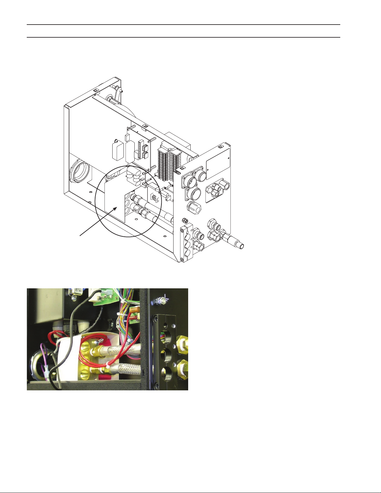
3.3 Plasma Gas Box Connections
1. To access the inside of the box: remove or unlock screws
and lift the box cover o to expose internal components.
2. Disassemble the strain relief/clamp block. (When apart,
this strain relief will allow placement of cables and hoses
without removing plugs and ttings.)
A. Remove two screws holding block together.
B. Insert cables for making connections inside box.
C. Reattach block.
Strain Relief / Clamp Block
Note:
Wires can be inserted in any of the three holes in
the Strain Relief / Clamp Block, only one power
source cable is used in picture below.
Pilot Arc Cable
Power Source Cable
22

SECTION 3 INSTALLATION
3.3.1 Plasma Gas Box Starter Box Connections
Arc Starter Box
TB1 – Pilot arc cable from the plasma power source.
TB4 – Connected to buss bar (lower back right hand
corner).
TB2 – Pilot Arc Torch cable from the torch leads.
Black Lead - 120 vdc input
TB1 TB4 TB2 Black Lead
Pilot Arc Cable
Buss Bar
View from underneath the Arc Starter Box
23

SECTION 3 INSTALLATION
3.3.2 Plasma Gas Box Torch Connections
To connect the torch see the following illustrations. Hook-up requires connection of the cut and start gas hoses,
shield gas hose, coolant hoses, air curtain hose, the pilot arc cable (TB2) and the Torch Tip / Electrical soft touch
wire on the PC board X4 terminal.
Torch Bundle Hose Connections
1 - Female old-style air water nut for Shield Gas connection
2 - B-IG ttings for Plasma Start gas and Plasma Cut gas. Ei-
ther hose can be attached in either location.
3 - Cooling Water Connections.
4 - Pilot Arc Cable - connects to TB2 underneath Arc Starter
Box.
5 - Torch Tip / Electrical soft touch wire - connects to PC
2
5
board at X4 terminal.
6 - Air Curtain Hose - to air curtain at torch tip
7 - Torch Grounding Stud (for CE units only).
4
3
1
2
1
6
3
7
5
24

SECTION 3 INSTALLATION
3.3.3 Plasma Gas Box Torch Cooling Water Connections
Coolant Connections To and From Power Source
When packaged with a torch and power supply at the factory,
connections are labeled. Additional labels are available if re-
O OUT
H
2
labeling becomes necessary. Tracing the Plasma Gas boxes interior lines can identify the proper connections. Flow switch is
located on the “IN” line.
H2O IN
Plasma Gas Box Rear View
Coolant Connections To And From Torch
Note arrows on ttings indicating coolant ow direction.
Coolant Out has right-hand threads.
Coolant In has left-hand threads.
Note:
Coolant hoses connect as shown from the
water cooler to the Plasma Gas box.
Plasma Gas Box
Rear View
25

SECTION 3 INSTALLATION
3.3.4 Power Source To Plasma Gas Box Buss Connection
1. Strip 4/0 (95 mm2) insulation, approximately 38 mm.
2. Insert 4/0 (95 mm2) cable in buss bar hole until copper
extends to the edge of the buss block.
3. Tighten locking screw(s) on cable.
Note:
The buss will accommodate these cables.
(1) 4/0 (95 mm2) - 400 amps
(2) 4/0 (95 mm2) - 800 amps
(3) 4/0 (95 mm2) - 1000 amps
Pilot Arc Cable
Buss Block
Power Source Cable
Careful attention while stripping insulation will make installation of
NOTICE
the 4/0 (95 mm2) cable in the buss easier. Do not spread or are the
copper conductors.
3.3.5 Plasma Gas Box PC Board Connections
X1-10 - +24 vdc Input
X1-9 - Sensor Input
X1-2 - Common / Chassis Ground
X4 - Torch Tip / Electrical soft touch wire
PE - Chassis Ground
Note:
For more detailed information, refer to PC
board schematic next page.
26

SECTION 3 INSTALLATION
25.07.2005 12:51:42 C:\Programme\EAGLE_V4-11\projects\2256510\2256510.sch (Sheet: 1/1)
PC Board Schematic
27
SECTION 3 INSTALLATION
3.4 Plasma Gas Box Nomex Insulation
Nomex Insulation
1. To access the inside of the box: remove or
unlock screws and lift the box cover o to
expose internal components.
2. Position Nomex insulation to prevent any
possible arcing between the buss and arc
start box terminals.
3. Replace enclosure of m3 Plasma System Plasma Gas Box.
28

SECTION 3 INSTALLATION
3.5 Plasma Gas Box Gas Connections
Gas Connections are made on the exterior of the box. Gas lines are connected to the back of the plasma gas box
from supply sources. Gas lines are connected to the front of the plasma gas box from the torch.
CAUTION
Unltered Gas Will Clog Proportional Valves
Dirt particles will clog small orices in proportional valves. All gas
supplies must have a 25 micron lter installed between supply and
gas regulator panel. ESAB Filter P/N 56998133 (replacement lter
element P/N 0560988406). Proportional valves contain no serviceable parts. Replace valve assembly with factory parts.
Plasma Gas Box Rear Gas Connections
Plasma Gas Box Front Gas Connections
29

SECTION 3 INSTALLATION
Gas Line Contamination Will Damage Proportional Valves.
Purge Gas Lines.
CAUTION
1
2
5
6
Before connecting gas delivery lines to the m3 Plasma System Plasma Gas Box, purge all lines thoroughly. Residue from the hose manufacturing process may clog/damage the proportional valves in your
m3 Plasma System Plasma Gas Box.
1. Purge gas and air lines completely before connecting
to 25 micron gas lters.
2. Connect oxygen, H-35, nitrogen and air lines to gas
lters.
3. Purge gas/air lines between shield gas box and m3
Plasma System Plasma Gas Box.
4. Connect gas/air lines to back of Plasma Gas box.
4
7
3
8
10
20
12
11
9
13
19
15
1 PG1
2 PG2
3 Air Curtain
4 PG2 Out
5 PG1 Out
6 Shield
7 Tor ch
8 14 Pin To B3 Lifter
9 8 Pin to Shield Box
10 10 Pin To B3 Lifter
11 H-35
12 Start Gas Selection (O2 N2 AIR)
13 Argon
14 H
15 Shield
16 Air Curtain
17 Cut Gas Selection (O2 N2 AIR)
18 H
19 LED Volt Meter
20
O IN
2
O OUT
2
Torch Cable Grounding Stud
(for CE units only)
14
18
17
16
30

SECTION 3 INSTALLATION
.75”
19.1 mm
ELECTRICITY CAN KILL!
BEFORE PERFORMING ANY MAINTENANCE OR ASSEMBLY OF THIS
WARNING
3.6 Shield Gas Box Introduction
The m3 Plasma System Shield Gas Box interfaces with the ESAB Vision machine controls and the EPP product line
of plasma power sources. An interface pc board receives voltage signals from the machine CNC that control proportional and solenoid valves. The result is CNC management of gas or shield gas delivery to the plasma torch.
Analog signal feedback is sent back to the CNC, creating a control loop.
3.7 Shield Gas Box Mounting (Bottom View)
If mounting the box is required:
EQUIPMENT, ENSURE THE POWER SOURCE EPP IS TURNED OFF AND
DISCONNECTED.
The box has four (1.10”) 28 mm threaded mounting holes in a pattern oset from longitudinal center. Note relationship of hole pattern to gauges and cable clamp.
.75”
19.1 mm
6.50”
165.1 mm
1.50”
38.1 mm
back
front
16. 00”
406.4 mm
2.50”
63.5 mm
31

SECTION 3 INSTALLATION
3.8 Shield Gas Box Connections
All connections are made on the exterior of the box. See diagrams and chart below.
Gas Line Contamination Will Damage Internal Components.
Purge Gas Lines.
CAUTION
3.8.1 Shield Gas Box front connections
Before connecting gas delivery lines to the m3 Plasma System Shield
Gas Box, purge all lines thoroughly. Residue from the hose manufacturing process may clog/damage the valves in your m3 Plasma System Shield Gas Box.
4
10
1
5
11
6
2
1 Power Cable
2 Ground Connection
3 Buss Connection Communication
4 CNC Out to Power Source
5 To Plasma Gas Box
6 Spare
7 To Air Curtain
8 To Plasma Gas 2
9 To Plasma gas 1
10 Spare
11 Power Cable Connector
3
7
8
9
4
5
6
View from inside showing connections
of Items 4, 5 & 6
32

SECTION 3 INSTALLATION
3.8.2 Shield Gas Box rear connections
1 Shield Gas Out
1
7
2
3
2 Air Curtain Inlet
3 Oxygen Inlet
4 N2 Inlet
5 Air Inlet
6 Check Valves (typical)
7 CH4 Inlet
4
5
6
m3 Gas Fittings Kit (0558005229, included w/ m3 system) Consists of the following:
P/N Description Quantity
36Z40 NUT HOSE B-A/W* .63-18F RH 2
136Z08 NUT HOSE B-I/G* .63-18M RH 1
3380 NUT HOSE B-OXY* .56-18F RH 1
3381 NUT HOSE B/ACET .56-18F LH 2
136Z07 NUT HOSE A-I/G* .38-24M RH 1
2 0 6 411 4 NPL PUSH A/A-W* 3/16 ID HOSE 1
03Z74 NPL PUSH B/SIZE 3/8* HOSE 5
3479 95 NPL PUSH B/A-W* 3/8 ID HOSE 1
0558006336 m3 PLASMA FILTER ASSEMBLY 1
20373 FLASH ARRESTOR ASSEMBLY 1
33

SECTION 3 INSTALLATION
3.9 Component Relationship Block Diagram
3
5
4
Air
(clean,
dry, oilfree shop
air for Air
Curtain
supply)
2
Air
(plasma
shield
supply
DIN
Qual-
ity ISO
8573-1)
CH
O
2
4
Argon
H-35N
3-phase w/
ground
2
3a
1
Cable
CNC
Pilot Arc
Power Cable
13
PS & WC Control Cables
Cable 4c
Pair
Cable 4 Twisted
25 Micron lters
Note:
Air Curtain or Bubble Muer can
be used here. See torch manual for
conditions.
9
10
14
Power Cable
Pilot Arc Cable
11
7
8
6
16
12
LED Volt Meter
15a = 10 Pin
15b = 14 Pin
Torch Lead
Encoder / Voltage
Height Control
17
Workpiece
Earth Ground
Work Table
34

SECTION 3 INSTALLATION
ITEM NUMBER PART NUMBER DESCRIPTION
1 05 58004 315 EPP-200, 200,230,380,415,460,575V
0558006470 EPP-400 400V, 50/60Hz CE
0558006471 EPP-400 460V, 60Hz
0558006472 EPP-400 575V, 60Hz
0558006473 EPP-600 400V, 50/60Hz CE
05 58006 474 EPP-600 460V, 60Hz
0558006475 EPP-600 575V, 60Hz
0558007800 EPP-201, 380/400V, 50/60Hz, CCC/CE
0558007801 EPP-201, 460V, 60Hz
0558007802 EPP-201, 575V, 60Hz
055800 7831 EPP-360, 380/400V, 50/60Hz, CCC/CE
0558006832 EPP-360, 460V, 60Hz
0558006833 EPP-360, 575V, 60Hz
0558007730 EPP-401/450, 380/400V, 50/60Hz CE
055800 7731 EPP-450, 460V, 60Hz
0558007732 EPP-450, 575V, 60Hz
0558007733 EPP-601, 380/400V, 50/60Hz, CCC/CE
0558007734 EPP-601, 460V, 60Hz
0558007735 EPP-601, 575V, 60Hz
2 0558006086 Junction Box, PS & WC
3 0558004837 Cable Control, WC, 5m (16’)
0558004838 Cable Control, WC, 10m (33’)
0558004839 Cable Control, WC, 20m (66’)
3a 0558004849 Cable Control, PS & WC, 5m (16’)
0558004850 Cable Control, PS & WC, 10m (33’)
05580 04851 Cable Control, PS & WC, 20m (66’)
0558004852 Cable Control, PS & WC, 40m (131’)
0558004853 Cable Control, PS & WC, 50m (164’)
0558004854 Cable Control, PS & WC, 60m (196’)
0558005237 Cable Control, PS & WC, 15m (49’)
0558005238 Cable Control, PS & WC, 30m (98’)
4 0558005246 Coolant Hose, 5m (16’)
0558005563 Coolant Hose, 10m (33’)
0558005564 Coolant Hose, 15m (49’)
0558005565 Coolant Hose, 20m (66’)
0558005247 Coolant Hose, 30m (98’)
0558005248 Coolant Hose, 40m (131’)
0558005567 Coolant Hose, 50m (164’)
0558005249 Coolant Hose, 60m (196’)
5 0558004400 Coolant Circulator PCC-10
05 58007515 Coolant Circulator PCC-11
35

SECTION 3 INSTALLATION
ITEM NUMBER PART NUMBER DESCRIPTION
6 0558006089 Hose, Plasma Gas #1, 1.5m (5’)
0558006090 Hose, Plasma Gas #1, 5m (16’)
0558006091 Hose, Plasma Gas #1, 6m (19’)
0558006092 Hose, Plasma Gas #1, 7m (23’)
0558006093 Hose, Plasma Gas #1, 8m (26’)
0558006094 Hose, Plasma Gas #1, 9m (30’)
0558006095 Hose, Plasma Gas #1, 10m (33’)
0558006096 Hose, Plasma Gas #1, 11m (36’)
0558006097 Hose, Plasma Gas #1, 12m (39’)
0558006098 Hose, Plasma Gas #1, 13m (43’)
0558006099 Hose, Plasma Gas #1, 14m (46’)
0558006100 Hose, Plasma Gas #1, 15m (49’)
0558 006101 Hose, Plasma Gas #1, 16m (52’)
0558 006102 Hose, Plasma Gas #1, 17m (56’)
0558 006103 Hose, Plasma Gas #1, 18m (59’)
0558 006104 Hose, Plasma Gas #1, 19m (62’)
0558006105 Hose, Plasma Gas #1, 20m (66’)
7 0558006106 Hose, Plasma Gas #2, 1.5m (5’)
0558 006107 Hose, Plasma Gas #2, 5m (16’)
0558 006108 Hose, Plasma Gas #2, 6m (19’)
0558 006109 Hose, Plasma Gas #2, 7m (23’)
0 55 8 0 0 6 110 Hose, Plasma Gas #2, 8m (26’)
0 55 8 0 0 6 111 Hose, Plasma Gas #2, 9m (30’)
0 55 8 0 0 6 112 Hose, Plasma Gas #2, 10m (33’)
0 55 8 0 0 6 113 Hose, Plasma Gas #2, 11m (36’)
0 55 8 0 0 6 114 Hose, Plasma Gas #2, 12m (39’)
0 55 8 0 0 6 115 Hose, Plasma Gas #2, 13m (43’)
0 55 8 0 0 6 116 Hose, Plasma Gas #2, 14m (46’)
0 55 8 0 0 6 117 Hose, Plasma Gas #2, 15m (49’)
0 55 8 0 0 6 118 Hose, Plasma Gas #2, 16m (52’)
0 55 8 0 0 6 119 Hose, Plasma Gas #2, 17m (56’)
05 58 00 612 0 Hose, Plasma Gas #2, 18m (59’)
05 58 00 6121 Hose, Plasma Gas #2, 19m (62’)
05 58 00 612 2 Hose, Plasma Gas #2, 20m (66’)
36

SECTION 3 INSTALLATION
ITEM NUMBER PART NUMBER DESCRIPTION
8 0558006200 Hose, Shield Gas, 1.5m (5’)
0558006201 Hose, Shield Gas, 5m (16’)
0558006202 Hose, Shield Gas, 6m (19’)
0558006203 Hose, Shield Gas, 7m (23’)
0558006204 Hose, Shield Gas, 8m (26’)
0558006205 Hose, Shield Gas, 9m (30’)
0558006206 Hose, Shield Gas, 10m (33’)
0558006207 Hose, Shield Gas, 11m (36’)
0558006208 Hose, Shield Gas, 12m (39’)
0558006209 Hose, Shield Gas, 13m (43’)
05580 06210 Hose, Shield Gas, 14m (46’)
0 55 8 0 0 6 211 Hose, Shield Gas, 15m (49’)
05 58 00 62 12 Hose, Shield Gas, 16m (52’)
05 58 00 6213 Hose, Shield Gas, 17m (56’)
0558 00 6214 Hose, Shield Gas, 18m (59’)
05 58006 215 Hose, Shield Gas, 19m (62’)
055 800 6216 Hose, Shield Gas, 20m (66’)
9 05 58 0 06 217 Hose, Air Curtain, 1.5m (5’)
055 8006218 Hose, Air Curtain, 5m (16’)
0558 00 6219 Hose, Air Curtain, 6m (19’)
0558006865 Hose, Air Curtain, 6.1m (20’)
0558006220 Hose, Air Curtain, 7m (23’)
05580 06221 Hose, Air Curtain, 8m (26’)
0558006222 Hose, Air Curtain, 9m (30’)
0558006223 Hose, Air Curtain, 10m (33’)
0558006224 Hose, Air Curtain, 11m (36’)
0558006225 Hose, Air Curtain, 12m (39’)
0558006226 Hose, Air Curtain, 13m (43’)
0558006227 Hose, Air Curtain, 14m (46’)
0558006228 Hose, Air Curtain, 15m (49’)
0558006229 Hose, Air Curtain, 16m (52’)
0558006230 Hose, Air Curtain, 17m (56’)
055800 6231 Hose, Air Curtain, 18m (59’)
0558006232 Hose, Air Curtain, 19m (62’)
0558006233 Hose, Air Curtain, 20m (66’)
37

SECTION 3 INSTALLATION
ITEM NUMBER PART NUMBER DESCRIPTION
10 0558004841 Air Curtain Hose 1.4m (4.5’)
0558004842 Air Curtain Hose 1.8m (6’)
0558004843 Air Curtain Hose 3.6m (12’)
0558004844 Air Curtain Hose 4.6m (15’)
0558004845 Air Curtain Hose 5.2m (17’)
0558004846 Air Curtain Hose 7.6m (25’)
0558005915 Fixture Assy SpeedLoader
0558005916 Nozzle Retainer SpeedLoader
0558005917 Tool Preassembly
11 0560941536 Shield Gas Box
12 05 60 941491 Plasma Gas Box
13 2239606 Power Junction Box
14 374 40 Air Curtain Assembly
37439 Bubble Muer
15a 05 60 94 012 9 Cable, PGC-B3, 10p, 1.4m (4.5’) - 2 Plug
0 56 09 4170 0 Cable, PGC-B3, 10p, 1.8m (6’) - 2 Plug
05 60 94 0135 Cable, PGC-B3, 10p, 3.6m (12’) - 2 Plug
0 56 09 4170 1 Cable, PGC-B3, 10p, 4.6m (15’) - 2 Plug
0560940138 Cable, PGC-B3, 10p, 5.2m (17’) - 2 Plug
05 60 94 0141 Cable, PGC-B3, 10p, 7.6m (25’) - 2 Plug
05 6094 0142 Cable, PGC-B3, 10p, 10.7m (35’) - 2 Plug
05 60 9414 82 Cable, PGC-B3, 10p, 7.6m (25’) - 1 Plug
05 60 9414 83 Cable, PGC-B3, 10p, 10.7m (35’) - 1 Plug
05 60 9414 84 Cable, PGC-B3, 10p, 13.7m (45’) - 1 Plug
05 60 9414 85 Cable, PGC-B3, 10p, 16.8m (55’) - 1 Plug
38

SECTION 3 INSTALLATION
ITEM NUMBER PART NUMBER DESCRIPTION
15b 056 094014 4 Cable, PGC-B3, 14p, 1.4m (4.5’) - 2 Plug
0560941702 Cable, PGC-B3, 14p, 1.8m (6’) - 2 Plug
05 6094 0147 Cable, PGC-B3, 14p, 3.6m (12’) - 2 Plug
0 56 09 4170 3 Cable, PGC-B3, 14p, 4.6m (15’) - 2 Plug
05 6094 0148 Cable, PGC-B3, 14p, 5.2m (17’) - 2 Plug
05 6094 0149 Cable, PGC-B3, 14p, 7.6m (25’) - 2 Plug
05 60 94 0152 Cable, PGC-B3, 14p, 10.7m (35’) - 2 Plug
05 60 9414 87 Cable, PGC-B3, 14p, 7.6m (25’) - 1 Plug
05 60 9414 88 Cable, PGC-B3, 14p, 10.7m (35’) - 1 Plug
05 60 9414 89 Cable, PGC-B3, 14p, 13.7m (45’) - 1 Plug
05 60 941490 Cable, PGC-B3, 14p, 16.8m (55’) - 1 Plug
16 0560939938 Cable, GS-PGC, 8p, 1.8m (6’)
0560939939 Cable, GS-PGC, 8p, 7.6m (25’)
0560939940 Cable, GS-PGC, 8p, 10.7m (35’)
05 60 939 941 Cable, GS-PGC, 8p, 13.7m (45’)
0560939942 Cable, GS-PGC, 8p, 16.8m (55’)
17 0558003849 Plasma Torch PT-36, 1.4m (4.5’)
0558003850 Plasma Torch PT-36, 1.8m (6’)
0558003852 Plasma Torch PT-36, 3.6m (12’)
0558005741 Plasma Torch PT-36, 4.3m (14’)
0558003853 Plasma Torch PT-36, 4.6m (15’)
0558003854 Plasma Torch PT-36, 5.2m (17’)
0558003856 Plasma Torch PT-36, 7.6m (25’)
39

SECTION 3 INSTALLATION
40

SECTION 4 OPERATION
4.0 Operation
4.1 Plasma Gas Box Operation
A major advantage of the m3 Plasma System Plasma Gas Box is that operating parameters are managed by the
machine CNC. There are no operating procedures necessary with the m3 Plasma System Plasma Gas Box. Management is accomplished either with manual inputs on the Vision cutting parameter screen or using the ESAB
system of Process Parameter Files.
Note:
Process Parameter Files (known by the acronyms … SDP or TDF) are les stored in the machine control
memory containing all necessary information for cutting a thickness and a material type. It is specic to
material, thickness, torch model, gas and material type. The information used to create the les can be
found in your torch manual. Refer to ESAB CNC Part Programming manual for more detail on the creation
and use of parameter les.
See CUT DATA MANUAL, P/N 0558006163 for cutting parameter set-
NOTICE
tings for using the m3 Plasma System Plasma Gas Box.
4.2 Plasma Gas Box Pressure Gauges
Pressure gauges display actual pressure to the torch. They provide visual feedback to the operator, and can be
helpful in spotting torch problems.
Note:
PG1 & PG2 are referred to as Start & Cut gas
Start Gas
(P G1)
Cut Gas
(PG2)
most of the time. Certain cutting conditions
require PG1 conditions only.
41

SECTION 4 OPERATION
4.3 Plasma Gas Box Pressure Switches
Pressure switches monitor line pressure and provide inputs to the CNC. If the pressure drops below 50 psi, the
CNC can shut the process down. Switches are in-line between the solenoid and the proportional valve for shield
gas 1 & 2, start gas and cut gas.
Plasma Gas Box
Gas Pressure Switch
42

SECTION 4 OPERATION
4.4 Shield Gas Box Operation
A major advantage of the m3 Plasma System Shield Gas Box is that operating parameters are managed by the
machine CNC. There are no operating procedures necessary with the m3 Plasma System Shield Gas Box. Management is accomplished either with manual inputs on the Vision cutting parameter screen or using the ESAB
system of Process Parameter Files.
Note:
Process Parameter Files (known by the acronyms … SDP or TDF) are les stored in the machine control
memory containing all necessary information for cutting a thickness and a material type. It is specic to
material, thickness, torch model, gas and material type. The information used to create the les can be
found in your torch manual. Refer to ESAB CNC Part Programming manual for more detail on the creation
and use of parameter les.
See CUT DATA MANUAL, P/N 0558006163 for cutting parameter set-
NOTICE
tings for using the m3 Plasma System Shield Gas Box.
43
SECTION 4 OPERATION
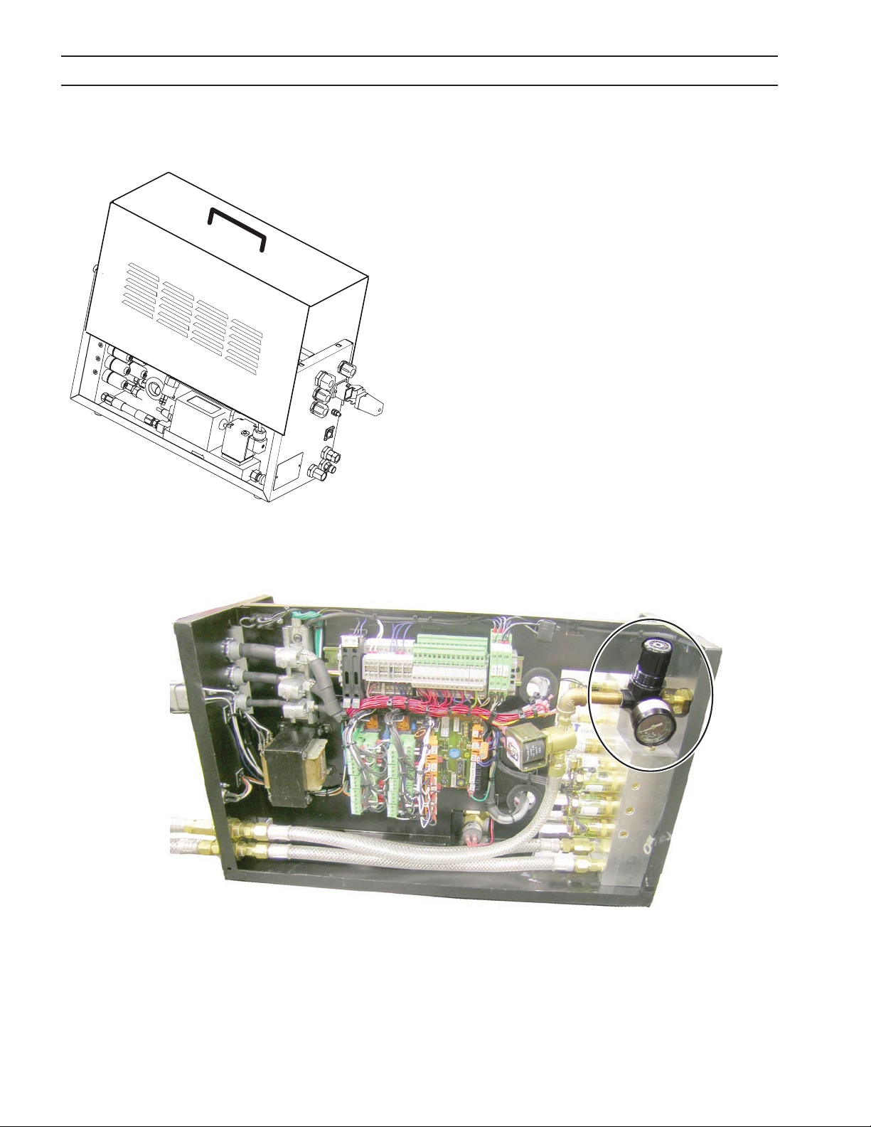
4.5 Shield Gas Box Air Regulator for Air Curtain
The Air Regulator displays actual air pressure to the torch.
It provides visual feedback to the operator, and can be
helpful in spotting torch problems.
To access the Air Regulator:
1. Remove the cover. No adjustment should be necessary
to the regulator. Regulator is factory set to 40 psi (2.8
bar) while owing.
44

SECTION 4 OPERATION
4.6 Shield Gas Box Check Valves
Check Valves stop backow between gas selections. Periodic purging of check valves is necessary to clear gas
lines. To purge lines simply unscrew caps on check valves to bleed the gas pressure.
45
Check Valves
(9 typical)

SECTION 4 OPERATION
46

SECTION 5 MAINTENANCE
5.0 Maintenance
5.1 Plasma Gas Box Maintenance
The m3 Plasma System Plasma Gas Box has proven to be a very reliable product. Regular maintenance is important for many years of trouble free use. This section contains a brief description of the most common problems,
schematics, and technical diagnostic tools.
ELECTRIC SHOCK CAN KILL!
WARNING
ALWAYS DISCONNECT POWER FROM THE EPP POWER SOURCE AND
THE CUTTING MACHINE BEFORE OPENING OR SERVICING THE m3
PLASMA SYSTEM PLASMA GAS BOX.
CAUTION
5.2 Plasma Gas Box Schematic (Plumbing Schematic)
Only Qualied Maintenance Personnel Should Repair And Maintain
This Equipment.
Shield IN Shield to Torch
Argon
H3 5-1
N2/O2/Air
PS 1
Spark Arrestor
PS 2
N2/O2/Air
Air Curtain To AIr Curtain
47

SECTION 5 MAINTENANCE
5.3 Plasma Gas Box Pressure Switches
Gas Pressure Switch monitors the pressure of plasma gas supply to the Plasma Gas box. One switch monitors
both O2. The other switch is used for monitoring alternate gas, either H-35, Air or N2.
Note:
H-35 is an industry name for a mixture of 65 % argon and 35% hydrogen.
Secondary Shield Switch monitors the pressure of the secondary shield gas in the shield box. These switches
are wired as an input to the CNC. Logic codes in the control look for a change of state (low/high) of the input
signals, therefore these switches cannot be jumpered out of the circuit. Both pressure switches are factory set
and non-adjustable to close at 50 PSI (3.45 Bar). They contain no serviceable parts. Replacement P/N 952920.
Plasma Gas Box
Gas Pressure Switch
48

0
.040"
(1 mm)
SECTION 5 MAINTENANCE
5.4 Spark Gap Of the Arc Starter Box (Plasma Gas Box)
Arc Starter Box
The m3 Plasma System Plasma Gas Box uses a high frequency arc starter to initiate the plasma arc within the cutting torch. The arc starter box is mounted in the upper right corner of the Plasma Gas box. The arc starter box
contains an adjustable spark gap.
The recommended spark gap setting is 0.040” (1,0 mm).
Decreased Spark Gap from 0.040” (1 mm):
HIGH
LOW
Starting Reliability
Spark Gap
Interference Damage
Risk of High Frequency
• NegativeEect-startingreliabilityisdecreased
• PositiveEect–smallerriskofhighfrequencyinterference
Increased Spark Gap from 0.040” (1 mm):
• NegativeEect–increaseddamageriskfromhighfrequency
interference
• PositiveEect-startingreliabilityincreased(toapointwhereit
doesn’t work at all).
High Frequency Interference Can Damage Machine Electronic Com-
CAUTION
ponents. Potentially damaging high frequency interference may result from increasing the spark gap beyond recommendation. This
electrical interference may nd its’ way to pc boards in the electronics cabinet or Vision control. The result will be failure of some portion of machine function. Do not set spark gap beyond recommended distance of 0.040” (1,0 mm).
49

SECTION 5 MAINTENANCE
ELECTRIC SHOCK CAN KILL!
WARNING
5.5 Spark Adjustment Procedure (Plasma Gas Box)
ALWAYS TURN POWER OFF BEFORE OPENING AND SERVICING THE
m3 PLASMA SYSTEM PLASMA GAS BOX.
1. Disconnect input power to plasma power source (EPP) and cutting machine.
2. Remove access cover from the arc starter box.
3. Use a 0.040” (1 mm) feeler gauge or shim to measure the spark gap setting.
4. Adjust as required. When correctly adjusted, there should be slight pressure felt when a back and forth motion is applied to the shim.
5. Replace cover.
50

1
2
3
4
5
SECTION 5 MAINTENANCE
5.6 Cooling Water Circuit (Plasma Gas Box)
The cooling water circuit consists of two reverse ow
check valves and a ow switch. It is a closed loop re-circulating system which cools the electrode and torch body of
the PT-36 torch. The PT-36 torch has an electrode, nozzle,
nozzle retaining cup, and torch body cooled by this system. The primary concern of the cooling water system is
the ow rate. Insucient cooling ow can result in severe
damage to the consumables and torch body. The cooling water ow switch is calibrated to close at or above a
1 Tor ch
2 To torch check valve
3 Flow Switch (In water cooler and/or
power supply
4 Return coolant check valve
5 Water cooler
ow rate of 1 gallon (3.8 liters) per minute. If the ow rate
drops below this rate, a signal is sent to the CNC and the
plasma system is shut down.
1 Buss Block
2 Coolant line – to torch (from cooler)
3 Coolant line – from torch (to cooler)
4 Flow Switch (In water cooler and/or power supply
5 Check Valve – from torch
6 Check Valve – to torch
2
1
5
3
6
51

SECTION 5 MAINTENANCE
5.7 Plasma Gas Schematic
Plasma gases are controlled with proportional valves mounted on the manifold.
Plasma Gas Box
Spark Arrestor
Shield
To Torch
N2/O2/Air
N2/O2/Air
To
AIr Curtain
Torch PG 1
Argon
H3 5-1
N2/O2/Air
Torch PG 2
Air Curtain - optional for under water cutting only
PS 1
0-9 bar
PV - PG1
PS 2
Shield
To Torch
PG
to Torch
0-10 m3/h
MFC - PG1
Air Curtain
52

SECTION 5 MAINTENANCE
5.8 Voltage Divider Adjustment Procedure
The Voltage Dividers or VDR’s can be adjusted to provide optimum cut and marking capability. Follow the procedure below to start tuning the cut and mark VDR. Once this range has been obtained more precise cuts can be
tuned in by adjusting the pot and making test cuts to gauge accuracy.
TB1-11 will be located here
VDR (cutting)
VDR Adjustment Pot
VDR (marking)
Procedure:
To adjust the VDR for cutting, place ohm meter leads between TB1-11 and chassis ground. With VDR hooked up
and in place as shown, the reading should be approximately 690 ohms.
To adjust the VDR for marking, place ohm meter leads between TB1-11 and chassis ground. With VDR hooked up
and in place as shown, the reading should be approximately 900 ohms.
To obtain a more accurate cut or mark, turn the pot adjustment screw and make a test cut. Adjust and test until
desired cut or mark is achieved. Ohm meter readings can vary according to cable lengths. Test cuts will have to
be made to ne tune the quality.
53

SECTION 5 MAINTENANCE
5.9 Voltage Divider Schematic
2K
Cutting Board - 56997963 Marking Board - 0560940947
54

SECTION 5 MAINTENANCE
5.10 Shield Gas Box Maintenance
The m3 Plasma System Shield Gas Box has proven to be a very reliable product. Regular maintenance is important for many years of trouble free use. Only trained personnel should perform maintenance on this equipment.
This section contains a brief description of the most common problems and schematics.
ELECTRIC SHOCK CAN KILL!
WARNING
ALWAYS DISCONNECT POWER FROM THE EPP POWER SOURCE AND
THE CUTTING MACHINE BEFORE OPENING OR SERVICING THE m3
PLASMA SYSTEM SHIELD GAS BOX.
CAUTION
This Equipment.
5.11 Shield Gas Box Schematic
Air
N2
O2
CH4
Fuel
Check
Valve
Only Qualied Maintenance Personnel Should Repair And Maintain
Air-1
N2 -1
O2 -1
CH4
O2-2
N2-2
Shield Gas Box
PS 3
0-10 m3/h
MFC - SG1
Shield
To Torch
PS 4
0-10 m3/h
MFC - SG2
N2/O2/Air
Air
Air-2
O2-3
N2-3
Air-3
Air Curtain
O2/N2/Air
To
AIr Curtain
55

SECTION 5 MAINTENANCE
5.12 Solenoid Replacement
ELECTRIC SHOCK CAN KILL!
WARNING
ALWAYS DISCONNECT POWER FROM THE EPP POWER SOURCE AND
THE CUTTING MACHINE BEFORE OPENING OR SERVICING THE m3
PLASMA SYSTEM SHIELD GAS BOX.
Common Problems:
Coil has malfunctioned, no ow to the •
MFC.
Shorted output.•
Procedure:
To replace a solenoid on the shield gas assembly,
unscrew solenoid nut on the faulty solenoid.
Shield Gas Assembly
Solenoid Valve
Solenoid Nut
Solenoid Coil
Remove solenoid assembly and unplug the attached
wires on the output board (make note of the red and
white wire connections).
Replace solenoid assembly, plug in the wires and replace nut on assembly.
56
Output Boards

SECTION 5 MAINTENANCE
5.13 Mass Flow Controller Replacement
Common Problems:
No ow through • Mass Flow Controller
(MFC).
Procedure:
1. Check LED indicator on top of MFC for power.
Mass Flow Controllers
Mass Flow Controller
2. Ensure gas is owing to the MFC. Refer to schematic for input ow setting. If no ow is present,
check gas and gas lines.
3. Check for gas passage through the MFC. When
gas is on and power is on MFC, gas should ow
through.
4. If no gas ows through, replace MFC. Replace
by unscrewing (4) four screws in bottom of MFC.
Remove cable and hose connections. Take note
of placement for reassembly.
5. Replace MFC and reconnect hoses and cables.
LED Power Indicator
57

SECTION 5 MAINTENANCE
5.14 Gas Filters
Unltered Gas Will Clog Proportional Valves
Gas lters must be installed in the gas supply lines in front of the
gas regulator panel. A 25 micron lter is required, P/N 56998133.
CAUTION
Replacement lter element P/N 0560988406.
All gases supplied to the m3 Plasma System Plasma Gas Box must be
ltered to 25 microns. Small orices in proportional valves will become clogged if lters are neglected or bypassed. Do Not Attempt
to Clean. Replacement of manifold assembly may be necessary. Replacement of proportional valves only is possible. Thoroughly ush
manifold and gas lines with N2 before reassembly. Because proportional valves contain the smallest gas passages, replacement or
cleaning of check valves is not recommended. Avoid any potential
problems by appropriately ltering plasma and shield gases.
58

SECTION 5 MAINTENANCE
59

SECTION 5 MAINTENANCE
5.15 Fluid Schematic – m3 Plasma System Plasma Gas Box and Shield Gas Box
Water Cooler PCC-10
Shield Gas Box
PS 3
Air
N2
Air-1
N2 -1
0-10 m3/h
MFC - SG1
Shield
To Torch
O2
CH4
Air
Fuel
Check
Valve
O2 -1
CH4
O2-2
N2-2
Air-2
O2-3
N2-3
Air-3
Air Curtain
PS 4
0-10 m3/h
MFC - SG2
N2/O2/Air
O2/N2/Air
To
AIr Curtain
60

SECTION 5 MAINTENANCE
Plasma Gas Box
Spark Arrestor
Shield
To Torch
N2/O2/Air
N2/O2/Air
To
AIr Curtain
Torch PG 1
Argon
H3 5-1
N2/O2/Air
Torch PG 2
Air Curtain - optional for under water cutting only
PS 1
0-9 bar
PV - PG1
PS 2
Shield
To Torch
PG
to Torch
0-10 m3/h
MFC - PG1
Air Curtain
61

SECTION 5 MAINTENANCE
62

SECTION 6 REPLACEMENT PARTS
6.0 Replacement Parts
6.1 General
Always provide the serial number of the unit on which the parts will be used. The serial number is stamped on
the unit nameplate.
6.2 Ordering
To ensure proper operation, it is recommended that only genuine ESAB parts and products be used with this
equipment. The use of non-ESAB parts may void your warranty.
Replacement parts may be ordered from your ESAB Distributor.
Be sure to indicate any special shipping instructions when ordering replacement parts.
Refer to the Communications Guide located on the back page of this manual for a list of customer service phone
numbers.
Note
Bill of material items that have blank part numbers are provided for customer information only.
Hardware items should be available through local sources.
63

A
A
1 1 . 2 8
7 . 5 0
4 . 5 0
0 . 7 5
0 . 3 8 R E F .
A
A
4 8
1 1 . 2 8
7 . 5 0
3 6
3 5
3 1
3 1
4 . 5 00 . 7 5
0 . 3 8 R E F .
8 2
8 5
( N O T E 8 )
4
SECTION 6 REPLACEMENT PARTS
6.3 Plasma Gas Box
64
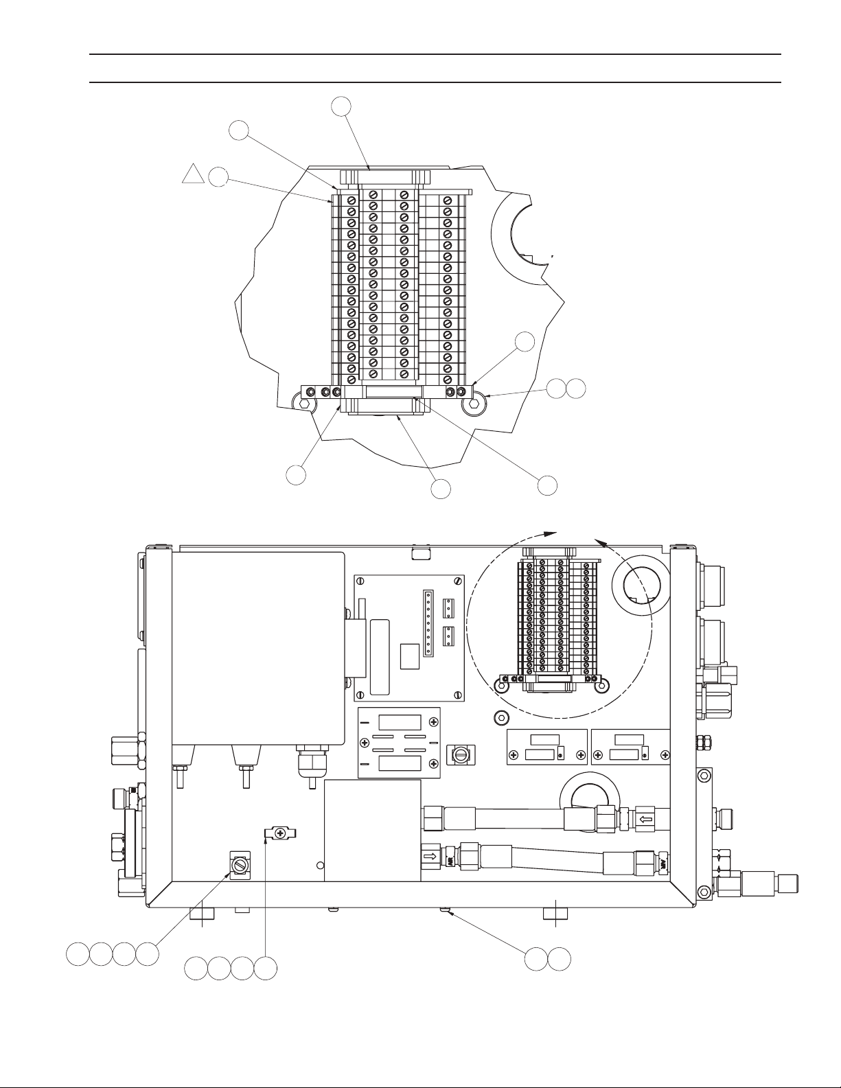
SECTION 6 REPLACEMENT PARTS
V I E W A - A
S C A L E 1 / 2
B
1 7 . 1 3
5 2
5 35 46 1
4 04 1
4 3
4 2
1 1
1 0
( N O T E 5 )
1 1 . 0 0 1 . 7 5
3
( N O T E 1 )
D E T A I L B
A
A
3 6
3 5
3 1
4 4
3 1
2 5 2 6
8 2
8 3
4
65

SECTION 6 REPLACEMENT PARTS
D
1 3
1
5 12 95 0
1 7
3
5 5
6
5 6
1 7
3 98 8
3 88 8
1 78 8
3 9
1 6
5 92 52 6
1 8
6 06 26 1
2
7
8
9
6 3
( N O T E 2 )
5 8
6 5 3 9
4 6 9 7 0 6 8
1 1
2 1 1 0
4 8
3 76 66 72 4
1 4 1 9 2 0 9 0
7 1
6 6
6 72 4
( N O T E 7 )
7 26 66 72 4
7 7
8 0
8 1
( 2 X )
1
8 6
8 9
3
29
51
50
66

SECTION 6 REPLACEMENT PARTS
D
1
5
6 6 6 8
1 7 8 8
1 1 1 0
1 4 1 9 6 4
3 9
6
5 92 52 6
6 06 26 1
6 3
(N O T E 2 )
5 8 6 5 3 9
(N O T E 3 )
6 8
1 7
( N O T E 7 )
7 32 7
7 4
3 8 8 8
3 8
3 9
1 3
8 6
3
9 1
4
D E T A I L D
S C A L E 1 : 1
1 6 8 8
8 8
1 5
3 0
1 48 7
1 6
(2 X )
1
8 8
2
4
9 2
4
1 1 1 0
D E T A I L D
1 5
3 0
1 4
8 7
1 6
(2 X )
1
2
4
4
99
Item #99 atta ched to in-
side of enc losure cover
67

SECTION 6 REPLACEMENT PARTS
Plasma Gas Box Parts List
ITEM QTY PART NUMBER DESCRIPTION
1 1 0558001055 ENCLOSURE HIGH FREQ BOX
2 1 0560940776 ASSY BUSS BAR m3 FLOW CONTRO L
3 1 0560940808 MASS FLOW PROPORTIONAL VALVE
4a 1 56997963 ASSY VOLTAGE DIVIDER BOARD - CUTTING
4b 1 0560940947 ASSY VOLTAGE DIVIDER BOARD - MARKING
5 1 0 0022 56510 BOARD TOOL TOUCH
6 2 0560940875 CLAMP, PANEL GAGE MOUNT
7 2 Helical Spring Lock Washer
ASME B 18.21 . 1 - 1/4 Regular. Carbon Steel
8 2 Washer A ANSI B 18.22. 1 - 1/4 - narrow - Type A
9 2 Hex Nut ANSI B 18.2.2 - 1/4 - 20
10 13 Spring Washer DIN 127 - A4
11 12 Hexagon Socket Button Head Screw ISO 7380 - M4 x 8
12
13 1 33053 STRAIN RELIEF 2” TORCH
14 3 2236750 TEE, STREET 1/4 NPTF x 1/4 NPTM
15 2 3390 ADAPTER 1/4 NPT - ’B’ FG
16 3 3389 ADAPTER 1/4 NPT - ’B’ OXY
17 7 10Z30 FITTING 1/4 NPT TO “B” A/W
18 2 0560940876 FITTING 1/4 NPTF TO 1/4 TUBE
19 2 2233664 FITTING 90 X 1/4 NPTM X 1/4 TU
20 1 4415150 0 COUPLING 1/4 NPT F-F
21 4 Plain Washer ANSI B 18.22 M - 4N
22 2 950167 GROMMET, RUBBER 1-1 /2 X 1-1/8
23 4 Hexagon Socket Button Head Screw ISO 7380 - M3 x 6
24 18 Spring Washer DIN 127 - A3
25 8 Spring Washer DIN 127 - A6
26 6 Hexagon Socket Button Head Screw ISO 7380 - M6 x 10
STD-000037
27 2 Cylinder Head Cap Screw DIN 912 - M6 x 16
28 2 Hexagon Socket Button Head Screw ISO 7380 - M6 x 12
29 8 Hex Nut DIN 934 - M6 STD-000024
30 1 952920 SWITCH PRESSURE NON-ADJUSTING
68

SECTION 6 REPLACEMENT PARTS
Plasma Gas Box Parts List
ITEM QTY PART NUMBER DESCRIPTION
31 2 2234485 END CLAMP
32
33
34 2 Washer DIN 125 - A 6.4
35 15 2237993 TERMINAL BLOCK MINI DBL LEVEL
36 1 2237994 END COVER MINI DBL LEVEL
37 1 636692 CONNECTOR AMPHEN MS3102A-18-19S
38 3 11 N1 6 ADAPTER 1/4 NPTTO ‘B’ FEMALE
39 4 74S 76 ADAPTER 1/4 NPT TO ‘B’ FEMALE
40 4 5700062900 WIRE TIE CRADLE
41 2 Slotted Cheese Head Screw DIN 84 - M5 x 8
42
43 6 Spring Washer DIN 127 - A5
44 1 0560940865 DIN RAIL MOUNTING
45 2 0560940862 FASTNER 1/4 TURN RECEPTACLE
46 2 0560940863 STUD 1/4 TURN SLOTTED HEAD
47 2 0560940864 RING RETAINER FOR 1/4 TURN FSTR
48 1 0560940779 ENCLOSURE WLDMT m3 FLOW CTRL
49 2 Slotted Cheese Head Screw DIN 84 - M5 x 10
50 8 Toothed Lock Washer DIN 6797 - A 6.4
51 2 0560940873 STUD, M6 - 1.0 X 1” PLATED
52 1 634220 CLIP GROUND
53 1 Recessed Pan Head Screw ISO 7045 - M4 x 8 - 4.8 - H
54
55 2 0560940874 GAGE, 2-1/2” PANEL MTG. 0-100
56 1 0560940879 CHECK VALVE 1/4 M IN 1/4 F OUT
57
58 1 2135 68 8 NIPPLE 1/4 NPT M-M
59 056 0940761 ASSY START GAS MANIFOLD
69

SECTION 6 REPLACEMENT PARTS
Plasma Gas Box Parts List
ITEM QTY PART NUMBER DESCRIPTION
60 1 0560938404 FILTER RFI POWER 2VB3 CORCOM
61 1 Toothed Lock Washer DIN 6797 - A 4.3 STD-000452
62 2 Recessed Pan Head Screw ISO 7045 - M4 x 5 - 4.8 - H STD-000453
63 1 0560940916 SHIELD, ELECTRICAL, BUSS BAR
64 1 33501007 ELBOW STREET 45 DEG 1/4 N P T
65 1 44251100 ELBOW 90° 1/4 NPT BRONZE
66 12 Cylinder Head Cap Screw DIN 912 - M3 x 12 STD-000457
67 12 Hex Nut DIN 934 - M3
68 8 Spring Washer DIN 127 - A 3.5
69 4 0560940922 STANDOFF, M3.5 - 0.6 X 22mm
70 8 Recessed Pan Head Screw JIS B 1111 - AM 3.5 x 6 - H
71 1 2062307 CONNECTOR AMPHEN DMS 3102A-22-23S
72 1 636665 CONNECTOR AMPHEN MS 3102A-20-27S
73 1 0560940777 CABLE CLAMP, m3 FLOW CONTROL
74 1 0560940778 CABLE CRADLE
75 1 0560940919 m3 HOSE ASSY SHIELD GAS
76 1 0560940920 m3 HOSE ASSY AIR CURTAIN
77 1 0560940918 m3 HOSE ASSY PLASMA GAS 1
78 2 0560940917 m3 HOSE ASSY COOLING WATER
79
80 1 570016 82 HOSE MANIFOLD TO GAGE
81 1 5700168 2 HOSE MFC TO GAGE
82 1 0560941602 ASSY, RELAY
83 1 0560941603 MODULE, SIGNAL RELAY
84 1 0560940921 m3 HOSE ASSY MFC IN
85 1 954075 NAMEPLATE 2.30 X 3.38
86 1 9 511 8 8 Lock Nut
87 1 44052550 Bushing 1/8 to 1/4 Brass
88 8 0 5609 4190 5 Adpt. Blkhd 1/4 NPT w/ Flats
89 1 527376 Strain Relief 1/2”
90 1 67101075 Nipple 1/4 NPT Close
91 1 6749 69 FILTER BOARD
92 1 20373 FLASHBACK ARRESTOR
94 8 0560943621 22mm Nylon Stando
99 1 0560945880 Shield, Electrical, Enclosure Cover
70

SECTION 6 REPLACEMENT PARTS
6.4 Start Gas Manifold (Plasma Gas Box)
2423
3
8
9
1
6
4 20 21
View B-B
10 12 13
14 15
19
See View B-B
3
2
71

SECTION 6 REPLACEMENT PARTS
Start Gas Manifold (Plasma Gas Box) Parts List
ITEM QTY PART NUMBER DESCRIPTION
1 1 0560940760 MANIFOLD, START GAS
2 1 952920 SWITCH PRESSURE NON-ADJUSTING
3 3 952921 VALVE SOLENOID 2-WAY MAN.MT.
4 1 0560939508 VALVE, PROPORTIONAL 833-354N03010
5 1 4440167500 PLUG PIPE 1/8 NPT
6 1 567596 MUFFLER 1/8 NPT BRASS
8 1 3390 ADAPTER 1/4 NPT -’B’ FG
9 1 10Z30 FITTING 1/4 NPT TO “B” A/W
10 3 0560 940763 “O” RING 11/16 X 13/16 X .07 VITON
11 2 Cylinder Head Cap Screw DIN 912 - M4 x 40
12 3 950654 BALL 1/2” DIA RUBBER
13 3 639678 TUBE
14 3 639669 SPRING 0.47 x 0.43 1 L
15 3 36358 PLUG MANIFOLD
16 1 6 810 0126 REDUCER HEX 3/8 NPT X 1/4 NPT
18 3 0560940762 STANDOFF MANIFOLD MOUNTING
19 1 44401900 PLUG 1/4 NPT SQR HD BRS
20 2 0 558 0 0128 2 “O” RING PROPORTIONAL VALVE 5mm X 1mm
21 1 0 558 001283 “O” RING PROPORTIONAL VALVE 4mm X 1mm
23 1 44052550 REDUCER HEX 1/4 NPT X 1/8 NPT
24 1 6 31475 FITTING, “A” TO I-G TO 1/8 NPT
72

SECTION 6 REPLACEMENT PARTS
6.5 Buss Bar Manifold (Plasma Gas Box)
2, 3
1
8
4
4
6, 7
5
73

SECTION 6 REPLACEMENT PARTS
Buss Bar Manifold (Plasma Gas Box) Parts List
ITEM QTY PART NUMBER DESCRIPTION
1 1 0560940772 BUSS BAR SOLDERED ASSY.
2 2 672225 STANDOFF, FIBERGLASS 1.25 LG.
3 4 0560940774 STUD (BUSS BAR INSUL)
4 2 10Z30 FITTING 1/4 NPT TO “B” A/W
5 3 0560940775 SET SCR 5/8-18 X 1/2 OVAL PNT
6 1 External Tooth Lock Washer Type A
ASME B18.21.1 - No. 10. Carbon Steel
7 1 Cross Recessed Fillister Head Machine Screw - Type IA
ANSI B18.6.3 - No. 10. - 32 - 3/8
8 1 0560940879 CHECK VALVE 1/4 F IN 1/4 M OUT
74
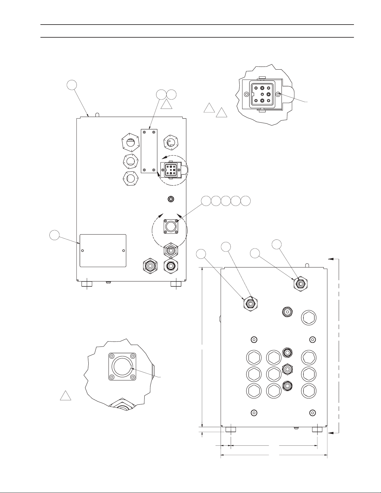
D E T A I L B
S C A L E 3 / 4
A
A
4 5
4 6
6 . 5 0
0 . 7 5
1 2 . 0 0
0 . 3 8
2 0
8 . 0 0
7 3 7 8
2 31 41 51 6
4 4
2 0
8 4
8 4
2
D E T A I L B
S C A L E 3 / 4
D E T A I L C
S C A L E 1 : 1
D E T A I L E
S C A L E 1 : 1
A
A
C
E
4 5
4 6
6 . 5 00 . 7 5
1 2 . 0 0
0 . 3 8
1
4 3 5 9
5 7
5 8 9
2 0
8 . 0 0
7 3 7 8
2 31 41 51 6
4 4
7 9
( N O T E 6 )
2 0
1
1
8 4
8 4
2
3
3
1 3 7
5 9
L U G T O O U T S I D E
O F E N C L O S U R E .
D E T A I L B
S C A L E 3 / 4
D E T A I L C
S C A L E 1 : 1
4 5
4 6
4 5
7 3 7 8
2 31 41 51 6
4 4
4 7
7 4
1
6 5
8 5
2
3
L U G T O O U T S I D E
O F E N C L O S U R E .
D E T A I L E
S C A L E 1 : 1
4 5
4 7
7 4
6 5
L U G T O O U T S I D E
O F E N C L O S U R E .
1
8 5
2
SECTION 6 REPLACEMENT PARTS
6.6 Shield Gas Box
75
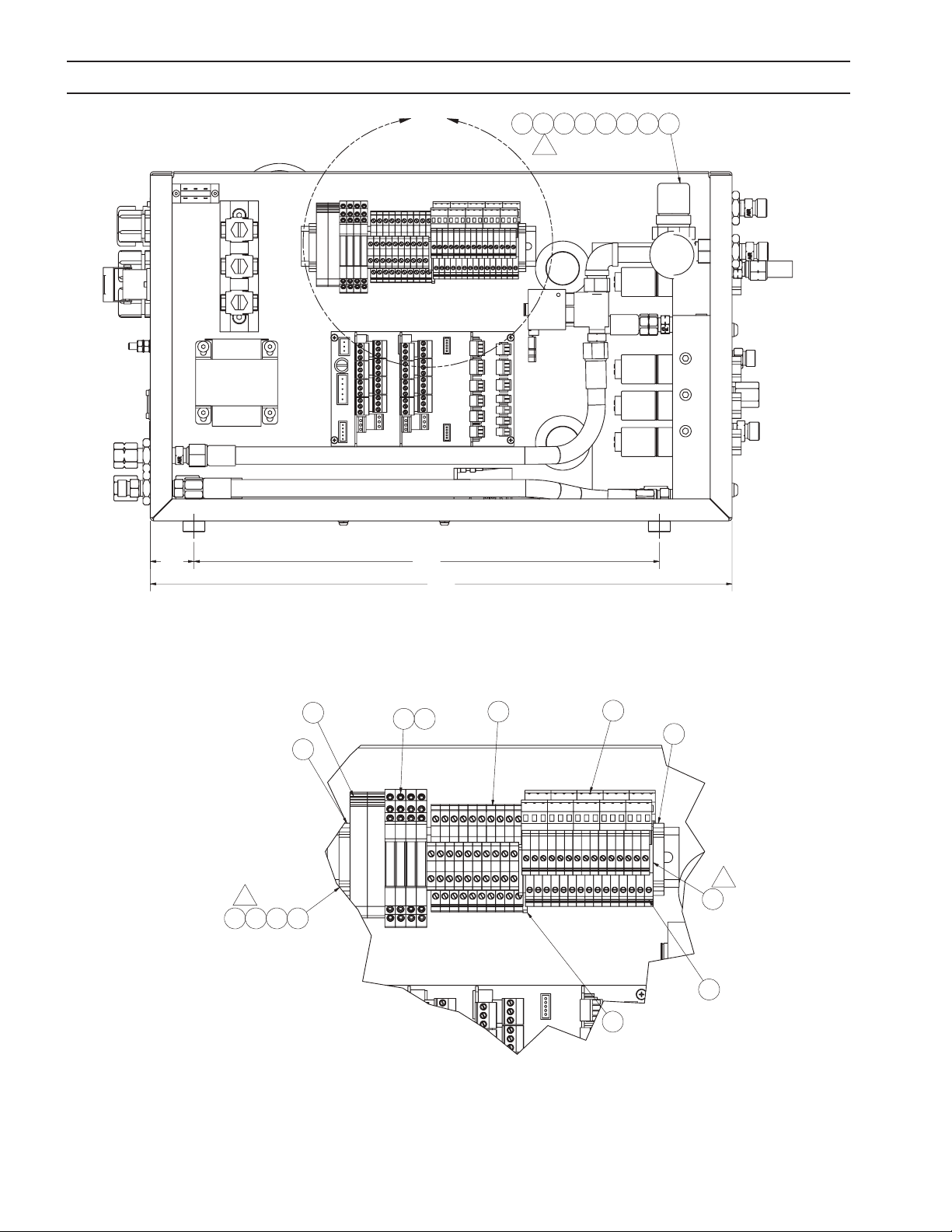
SECTION 6 REPLACEMENT PARTS
B
1 6 . 0 0
1 . 5 0
2 0 . 0 0
6 . 5 00 . 7 5
1 2 . 0 0
0 . 3 8
2 0
52 94 0
1 1
2 06 66 3
6 3
8 . 0 0
2 0
8 4
8 4
3
D E T A I L B
4 5
4 6
4 5
7 3
7 8
2 3
1 4
1 51 6
4 4
4 7
7 4
6 5
8 5
2
2
76

SECTION 6 REPLACEMENT PARTS
5 0
4 9
4 8
4 1 8 3 7 3 8
43 93 4
4 2
5 5
5 45 6
3 6 3 7
2 0
2 1
8 0
6 7 5 8 5 7
21 21 37 6
7 57 7
5 3
2 4
2
2
2
3
1 3 9
3
77

SECTION 6 REPLACEMENT PARTS
D E T A I L D
S C A L E 1 : 1
D
7
5 2
5 1
3 1
5 0
4 9
4 8
4 1 8 3 7 3 8
43 93 4
4 2
5 5
5 45 6
1 92 12 72 5
2 0
2 1
6 9
6 8
2 1
7 0 7 2 71
6 4
2 1
3 0 8 4
2 7 8 4
2 1 8 4
8 0
2 4
6 7 5 8 5 7
21 21 37 6
7 57 7
5 3
2 4
2
6 4
1 7
2
2
8 2
3
6 3
1 3 8
3
24
146
78

SECTION 6 REPLACEMENT PARTS
B
1 6 . 0 01 . 5 0
2 0 . 0 0
6 . 5 00 . 7 5
1 2 . 0 0
0 . 3 8
1
3 1 5 1 6 1 4
2 0
1 9
1 82 52 6
52 94 01 12 06 66 36 3
8 . 0 0
4 0 2 1 6 3
1 61 41 5
( N O T E 6 )
6 3 4 0 2 1
7 9
( N O T E 6 )
2 0
8 4
8 4
2
3
79

SECTION 6 REPLACEMENT PARTS
Shield Gas Box Parts List
ITEM QTY PART NUMBER DESCRIPTION
1 1 0560940923 Enclosure, SF3 Flow Control
2 1 2237924 MB03 MAIN BOARD ASSEMBLY
3 2 0560940808 MASS FLOW CONTROL VALVE
4 1 0560941466 TRANSFORMER ASSY
5 1 522368 REGULATOR AIR WITH GAGE
6
7 1 0560940926 ASSY, SHIELD GAS MANIFOLD SF3
8 3 2236432 CLIP, STIRRUP .32 - .47 DIA .
9 1 0 5 6 0 9 3 8111 CONN ASIOB FEMALE 5 PIN
10
11 1 950249 VALVE, 2-WAY 1/4 NPT 24V 60/50HZ
12 1 2237927 ANALOG CARD ASSEMBLY
13 2 0002256475 RELAY OUTPUT CARD ASSY
14 8 Washer DIN 125 - A 4.3
15 8 Spring Washer DIN 127 - A 4
16 8 Hexagon Socket Button Head Screw IS0 7380-M4 x 8
17 1 0560995891 ELBOW STREET 90 1/4 NPTF x 1/4 NPTM
18 1 3390 ADAPTER 1/4 NPT - ’B’ FG
19 3 2236750 TEE, STREET 1/4 NPTF x 1/4 NPTM
20 4 10Z30 FITTING 1/4 NPT TO “B-A/W
21 7 3389 ADAPTER 1/4 NPT -’B’OXY
22
23 1 0 56 094146 5 DIN RAIL
24 2 527376 STRAIN RELIEF 1/2” (1/4-3/8” Insert)
25 2 952920 SWITCH PRESSURE NON-ADJUSTING
26 2 44052550 REDUCER HEX 1/4 NPT X 1/8 NPT
27 2 74S 76 ADAPTER 1/4 NPT TO ‘B’ FEMALE
28
29 1 44352230 NIPPLE, PIPE 1/4 X 2 BRASS
30 1 11 N1 6 ADAPTER 1/4 NPT TO ‘B’ FEMALE
80

SECTION 6 REPLACEMENT PARTS
Shield Gas Box Parts List
ITEM QTY PART NUMBER DESCRIPTION
31 2 950167 GROMMET,RUBBER 1-1/2 X 1-1/8
32
33
34 2 Spring Washer DIN 127 - A5
35
36 4 Hexagon Socket Button Head Screw ISO 7380 - M6 x 10
STD-000037
37 8 Spring Washer DIN 127 - A6
38 8 Hexagon Socket Button Head Screw ISO 7380 - M6 x 12
39 4 Hexagon Socket Button Head Screw ISO 7380 - M5 x 12
40 3 4425110000 ELBOW 1/4 NPT BRONZE
41 1 0560940925 RAIL, GROUND CLAMP
42 1 0560940912 Switch , VoItage Select Slide
43 1 0560938112 CONN FLANGE ASIOB
44 1 0 2237993 TERMINAL BLOCK MINI DBL LEVEL
45 2 2234485 END CLAMP
46 2 2234477 FUSE HOLDER
47 1 5 2237987 TERM BLOCK DBL LEVEL W/COMB
48 1 0 560 9414 63 ASSY, HOSE, PLASMA GAS 1
49 1 056 09 41461 ASSY, HOSE, AIR CURTAIN
50 1 0 56 09 41462 ASSY, HOSE, PLASMA GAS 2
51 1 056 09 41459 ASSY, HOSE, SHIELD GAS 1
52 1 0560941460 ASSY, HOSE, SHIELD GAS 2
53 4 Hexagon Socket Button Head Screw IS0 7380 - M3 x 6
54 6 Spring Washer DIN 127 - A3
55 2 Hexagon SocketButton Head Screw ISO 7380 - M3 x 10
56 2 Hex Nut DIN 934 - M 3
57 6 Hex Nut DIN 934 - M 2.5
58 6 Spring Washer DIN 127 - A 2.5
59 6 Cylinder Head Cap Screw DIN 912 - M 2.5 x 8
81

SECTION 6 REPLACEMENT PARTS
Shield Gas Box Parts List
ITEM QTY PART NUMBER DESCRIPTION
60
61
62
63 1 639501 NIPPLE 1/4“ HEX BRASS
64 2 6 39 110 VALVE CHECK OXYGEN
65 1 2237994 END COVER MINIDBL LEVEL
66 6 950906 TERM INLINE FML .25 X 18-22 AWG
67 1 0560942023 ASSY MALE CONN PWR
68 1 0560941600 ASSY, HOSE, SHIELD GAS 1
69 1 0560941601 ASSY, HOSE, SHIELD GAS 2
70 1 0560940873 STUD, GND. 1/4 - 20 X 1” PLATED
71 4 Toothed Lock Washer DIN 6797 -J 6.4 STD-000483
72 4 Hex Nut DIN 934 - M6 STD-000024
73 4 0560941602 ASSY, RELAY
74 20 2213249 3 PIN CONNECTOR
75 4 56997679 BL 3.5/2/S N 2 PIN PLUG
76 6 56995340 BL 3.5/3/180 3 PIN PLUG
77 3 5 69953 41 BL 3.5/4/180 4 PIN PLUG
78 4 0560941604 MODULE, POWER RELAY
79 1 954075 NAMEPLATE 2.30 X 3.38
80 1 201056 0 STRAIN RELIEF 3/4”
81
82 1 0560942026 ASSY FEMALE CONN PWR
83
84 5 0 560 9419 05 ADPT BLKHD 1/4 NPT W/ FLATS
85 1 2770891 PHOENIX END COVER
137 1 05 609 42021 COVER PLT SHIELD GAS BOX M3 PLASMA
138 1 2059603 TEE 1/4 NPT FFF
139 1 0560985522 CHECK VALVE FUEL GAS
140 ref 0560988032 5 A SLOW BLOW
141 ref 0560939203 1.0 AMP SLOW BLOW
142 ref 0560943657 0.5 A SLOW BLOW
146 1 526 651 STRAIN RELIEF, 1/2 3/81/2” INSERT
82

SECTION 6 REPLACEMENT PARTS
6.7 Shield Gas Manifold (Shield Gas Box)
12
12
10
9, Oxygen
4, typ. 13 plcs
7, Nitrogen
10, Methane
See View A-A
9
7
9
2
8, Air
83
11
5
6
3
1
View A-A

SECTION 6 REPLACEMENT PARTS
Shield Gas Manifold (Shield Gas Box) Parts List
ITEM QTY PART NUMBER DESCRIPTION
1 10 0560940763 “O” RING 11/16 X 13/16 X .07 VITON
2 1 0560940899 SHIELD MANIFOLD
3 10 36358 PLUG MANIFOLD
4 13 4440167500 PLUG PIPE 1/8 NPT
5 10 639669 SPRING 0.47x0.43 1 L
6 10 639678 TUBE
7 2 74S76 ADAPTER 1/4 NPT TO ‘B’ FEMALE
8 1 10Z30 FITTING 1/4 NPT TO “B” A/W
9 3 3389 ADAPTER 1/4 NPT - ‘B’ OXY
10 2 3390 ADAPTER 1/4 NPT - ‘B’ FG
11 10 950654 BALL 1/2” DIA RUBBER
12 10 952921 VALVE SOLENOID 2-WAY MAN. MT.
84

NOTES
85

NOTES
86

REVISION HISTORY
1. Original release - 05/2006
2. 06/2006 - Changes made through out the manual: updated ip-top covers, gas lters, added hose ttings kit, various
editorial changes, updated bom’s, added previously uncompleted information.
3. 12/2006 - Changes per cutting systems CN #064113. Changes made to various pictures of the shield gas and plasma
gas boxes. New pictures show new handle, strain relief & power cable connector for shield gas box. Plasma gas box
has new strain relief connector. Added P/N 20373, Flash Arrestor to the m3 Gas Fittings Kit, P/N 0558005229. Added
LED Volt Meter to the component block diagram. Updated schematics to show check valve & spark arrestor placement.
Updated 2.3 System Gas Requirements to show new information and match torch manual.
4. 06/2007 - Removed ground wires from illustration page 24, chgd item 1 p/n’s page 35, chgd item 17 p/n’s page 39,
revised note to call for correct cut data manual page 41 & 43, del note from page 52.
5. 02/2008 - Added second Voltage Divider Board (0560940947) to Pages 54 and 68 per e-mail request.
6. 10/2008 - Added chassis grounding stud and updated replacement parts / schematics.
87

ESAB Welding & Cutting Products, Florence, SC Welding Equipment
COMMUNICATION GUIDE - CUSTOMER SERVICES
A. CUSTOMER SERVICE QUESTIONS:
Telephone: (800)362-7080 / Fax: (800) 634-7548 Hours: 8:00 AM to 7:00 PM EST
Order Entry Product Availability Pricing Order Information Returns
B. ENGINEERING SERVICE:
Telephone: (843) 664-4416 / Fax : (800) 446-5693 Hours: 7:30 AM to 5:00 PM EST
Warranty Returns Authorized Repair Stations Welding Equipment Troubleshooting
C. TECHNICAL SERVICE:
Telephone: (800) ESAB-123/ Fax: (843) 664-4452 Hours: 8:00 AM to 5:00 PM EST
Part Numbers Technical Applications Specications Equipment Recommendations
D. LITERATURE REQUESTS:
Telephone: (843) 664-5562 / Fax: (843) 664-5548 Hours: 7:30 AM to 4:00 PM EST
E. WELDING EQUIPMENT REPAIRS:
Telephone: (843) 664-4487 / Fax: (843) 664-5557 Hours: 7:30 AM to 3:30 PM EST
Repair Estimates Repair Status
F. WELDING EQUIPMENT TRAINING
Telephone: (843)664-4428 / Fax: (843) 679-5864 Hours: 7:30 AM to 4:00 PM EST
Training School Information and Registrations
G. WELDING PROCESS ASSISTANCE:
Telephone: (800) ESAB-123 Hours: 7:30 AM to 4:00 PM EST
H. TECHNICAL ASST. CONSUMABLES:
Telephone : (800) 933-7070 Hours: 7:30 AM to 5:00 PM EST
IF YOU DO NOT KNOW WHOM TO CALL
Telephone: (800) ESAB-123
Fax: (843) 664-4462
Hours: 7:30 AM to 5:00 PM EST
or
visit us on the web at http://www.esabna.com
The ESAB web site oers
Comprehensive Product Information
Material Safety Data Sheets
Warranty Registration
Instruction Literature Download Library
Distributor Locator
Global Company Information
Press Releases
Customer Feedback & Support
0558005487 10 / 2008
 Loading...