


Precision Plasmarc
Plasma Gas Box & Shield Gas Box
Plasma Gas Box
Shield Gas Box
Instruction Manual (EN)
0558007535

BE SURE THIS INFORMATION REACHES THE OPERATOR.
YOU CAN GET EXTRA COPIES THROUGH YOUR SUPPLIER.
CAUTION
These INSTRUCTIONS are for experienced operators. If you are not fully familiar with the
principles of operation and safe practices for arc welding and cutting equipment, we urge
you to read our booklet, “Precautions and Safe Practices for Arc Welding, Cutting, and
Gouging,” Form 52-529. Do NOT permit untrained persons to install, operate, or maintain
this equipment. Do NOT attempt to install or operate this equipment until you have read
and fully understand these instructions. If you do not fully understand these instructions,
contact your supplier for further information. Be sure to read the Safety Precautions before installing or operating this equipment.
USER RESPONSIBILITY
This equipment will perform in conformity with the description thereof contained in this manual and accompanying labels and/or inserts when installed, operated, maintained and repaired in accordance with the instructions provided. This equipment must be checked periodically. Malfunctioning or poorly maintained equipment
should not be used. Parts that are broken, missing, worn, distorted or contaminated should be replaced immediately. Should such repair or replacement become necessary, the manufacturer recommends that a telephone
or written request for service advice be made to the Authorized Distributor from whom it was purchased.
This equipment or any of its parts should not be altered without the prior written approval of the manufacturer.
The user of this equipment shall have the sole responsibility for any malfunction which results from improper
use, faulty maintenance, damage, improper repair or alteration by anyone other than the manufacturer or a service facility designated by the manufacturer.
READ AND UNDERSTAND THE INSTRUCTION MANUAL BEFORE INSTALLING OR OPERATING.
PROTECT YOURSELF AND OTHERS!
114

TABLE OF CONTENTS
Section / Title Page
1.0 Safety Precautions ..................................................................................117
2.0 Description...........................................................................................11 9
2.1 System Introduction ...........................................................................11 9
2.2 m3 Plasma System Plasma Gas Box, Shield Gas Box and PT-36 ...................................11 9
2.3 System Gas Requirements..................................................................... 120
2.4 Plasma Gas Box Water Supply Requirements ................................................... 12 0
2.5 Plasma Gas Box Electrical Input Requirements ................................................. 12 0
2.6 Shield Gas Box Electrical Input Requirements .................................................. 12 0
2.7 System Accessories ........................................................................... 12 0
2.8 Plasma Gas Box Dimensions....................................................................121
2.9 Shield Gas Box Dimensions.................................................................... 12 2
3.0 Installation .......................................................................................... 12 3
3.1 Plasma Gas Box Introduction ..................................................................12 3
3.2 Plasma Gas Box Mounting (Bottom View) ...................................................... 12 3
3.3 Plasma Gas Box Connections .................................................................. 12 4
3.4 Plasma Gas Box Nomex Insulation ............................................................ 13 0
3.5 Plasma Gas Box Gas Connections...............................................................131
3.6 Shield Gas Box Introduction ................................................................... 133
3.7 Shield Gas Box Mounting (Bottom View)....................................................... 13 3
3.8 Shield Gas Box Connections................................................................... 13 4
3.9 Component Relationship Block Diagram....................................................... 13 6
4.0 Operation . . . . . . . . . . . . . . . . . . . . . . . . . . . . . . . . . . . . . . . . . . . . . . . . . . . . . . . . . . . . . . . . . . . . . . . . . . . . . . . . . . . . . . . . . . . 14 3
4.1 Plasma Gas Box Operation .................................................................... 143
4.2 Plasma Gas Box Pressure Gauges .............................................................. 143
4.3 Plasma Gas Box Pressure Switches ............................................................. 14 4
4.4 Shield Gas Box Operation ..................................................................... 14 5
4.5 Shield Gas Box Air Regulator for Air Curtain .................................................... 14 6
4.6 Shield Gas Box Check Valves .................................................................. 147
115

TABLE OF CONTENTS
116

SECTION 1 SAFETY PRECAUTIONS
1.0 Safety Precautions
Users of ESAB welding and plasma cutting equipment have the ultimate responsibility for ensuring that anyone
who works on or near the equipment observes all the relevant safety precautions. Safety precautions must meet
the requirements that apply to this type of welding or plasma cutting equipment. The following recommendations
should be observed in addition to the standard regulations that apply to the workplace.
All work must be carried out by trained personnel well acquainted with the operation of the welding or plasma
cutting equipment. Incorrect operation of the equipment may lead to hazardous situations which can result in
injury to the operator and damage to the equipment.
1. Anyone who uses welding or plasma cutting equipment must be familiar with:
- its operation
- location of emergency stops
- its function
- relevant safety precautions
- welding and / or plasma cutting
2. The operator must ensure that:
- no unauthorized person stationed within the working area of the equipment when it is started up.
- no one is unprotected when the arc is struck.
3. The workplace must:
- be suitable for the purpose
- be free from drafts
4. Personal safety equipment:
- Always wear recommended personal safety equipment, such as safety glasses, ame proof
clothing, safety gloves.
- Do not wear loose tting items, such as scarves, bracelets, rings, etc., which could become
trapped or cause burns.
5. General precautions:
- Make sure the return cable is connected securely.
- Work on high voltage equipment may only be carried out by a qualied electrician.
- Appropriate re extinquishing equipment must be clearly marked and close at hand.
- Lubrication and maintenance must not be carried out on the equipment during operation.
117

SECTION 1 SAFETY PRECAUTIONS
WELDING AND PLASMA CUTTING CAN BE INJURIOUS TO YOURSELF AND
OTHERS. TAKE PRECAUTIONS WHEN WELDING OR CUTTING. ASK FOR
WARNING
ELECTRIC SHOCK - Can kill.
- Install and earth (ground) the welding or plasma cutting unit in accordance with applicable standards.
- Do not touch live electrical parts or electrodes with bare skin, wet gloves or wet clothing.
- Insulate yourself from earth and the workpiece.
- Ensure your working stance is safe.
FUMES AND GASES - Can be dangerous to health.
- Keep your head out of the fumes.
- Use ventilation, extraction at the arc, or both, to take fumes and gases away from your breathing zone
and the general area.
YOUR EMPLOYER’S SAFETY PRACTICES WHICH SHOULD BE BASED ON
MANUFACTURERS’ HAZARD DATA.
ARC RAYS - Can injure eyes and burn skin.
- Protect your eyes and body. Use the correct welding / plasma cutting screen and lter lens and wear
protective clothing.
- Protect bystanders with suitable screens or curtains.
FIRE HAZARD
- Sparks (spatter) can cause re. Make sure therefore that there are no inammable materials nearby.
NOISE - Excessive noise can damage hearing.
- Protect your ears. Use earmus or other hearing protection.
- Warn bystanders of the risk.
MALFUNCTION - Call for expert assistance in the event of malfunction.
READ AND UNDERSTAND THE INSTRUCTION MANUAL BEFORE INSTALLING OR OPERATING.
PROTECT YOURSELF AND OTHERS!
118

SECTION 2 DESCRIPTION
2.0 Description
2.1 System Introduction
The m3 Plasma System is a streamlined, high performance-cutting package designed for use exclusively with the
ESAB CNC. This advanced technology integrates gas and water control into the machine CNC.
Using a system of electronic valves driven by CNC outputs, this system:
dramatically reduces the amount of Plasma Gas hardware necessary to control the plasma torch.•
reduced purge time/increased part throughput .•
simplied operation with gas and water ow rates are controlled by the ESAB CNC process parameter •
screen.
allows for programmed/automated control of uid and water ow rates using SDP Files (SchneidDaten-•
Paket = Cutting Data Package, see Vision control and programming manuals for details on SDP Files.
Data used to generate SDP les can be found in your model specic torch manual.) SDP les can also
be referred to as TDF les (Technology Data Files).
to be used with the PT-36 cutting torch. •
Plasma Gas Box
Shield Gas Box
2.2 m3 Plasma System Plasma Gas Box, Shield Gas Box and PT-36
The complete m3 cutting system requires a variety of components. See section 3.9, Component Relationship
Block Diagram for components and hook-up.
119

SECTION 2 DESCRIPTION
2.3 System Gas Requirements
Argon 125 PSI (8,6 bar) with 0.25” NPT, 99.995% purity, Filtered to 25 microns
Nitrogen 125 PSI (8,6 bar) with 0.25” NPT, 99.99% purity, Filtered to 25 microns
Oxygen 125 PSI (8,6 bar) with 0.25” NPT, 99.5% purity, Filtered to 25 microns
H-35 (Argon/Hydrogen) 75 PSI (5,2 bar), Speciality Gas, 99.995% purity, Filtered to 25 microns
Methane 75 PSI (5,2 bar) with 0.25” NPT, 93% purity, Filtered to 25 microns
Compressed Air
(Air Curtain )
Compressed Air
(Pro cess)
2.4 Plasma Gas Box Water Supply Requirements
Cooling Water ......................................................................................175 PSI (12,1 bar), 1.5 gallons per minute (5.68 liters/minute)
2.5 Plasma Gas Box Electrical Input Requirements
80 PSI (5,5 bar) with 0.25” NPT, clean, dry, oil-free and ltered to 25 microns
80 PSI @ 1200cfh (5,5 bar @ 35 m3h) ltered to 25 microns
DIN Quality ISO 8573-1
Oil quality mg/m3 = 0.1 class 2
Particle Size 0.1um class 1
Temparature +3 C class 4
Voltage Supply +24 VDC for proportional valves, mfc
+15 VDC for pressure switch
Voltage Signals 24 VAC input to start gas solenoid valve
120 VAC input to arc starter
0-10 VDC input to proportional valves
0-10 VDC for mass ow valve
2.6 Shield Gas Box Electrical Input Requirements
Voltage Supply +24 VDC for 120/230 transformer and I/O board
+24 VDC for proportional valves and mfc’s
2.7 System Accessories
Coolant Hose Adaptor Kit ............................................................................................ 0558006698
Adapter Coolant EPP-200 ..............................................................................................0 55800 6162
120

SECTION 2 DESCRIPTION
2.8 Plasma Gas Box Dimensions
11 . 2 8 ”
286.5 mm
17.1 3 ”
435.1 mm
7. 2 5 ”
184.2 mm
121

SECTION 2 DESCRIPTION
2.9 Shield Gas Box Dimensions
12 .0 0 ”
304.8 mm
8.00”
203.2 mm
20.00”
508.0 mm
122

SECTION 3 INSTALLATION
2.00”
50.8 mm
3.0 Installation
ELECTRICITY CAN KILL!
BEFORE PERFORMING ANY MAINTENANCE OR ASSEMBLY OF THIS
WARNING
3.1 Plasma Gas Box Introduction
The m3 Plasma System Plasma Gas Box interfaces with the ESAB Vision machine controls and the EPP product
line of plasma power sources. An interface pc board receives voltage signals from the machine CNC that control
electronic valves. The result is CNC management of gas or shield gas delivery to the plasma torch. Analog signal
feedback is sent back to the CNC, creating a control loop.
3.2 Plasma Gas Box Mounting (Bottom View)
EQUIPMENT, ENSURE THE POWER SOURCE EPP IS TURNED OFF AND
DISCONNECTED.
If mounting the box is required:
The box has four (1.10”) 28 mm threaded mounting holes in a pattern oset from longitudinal center. Note relationship of hole pattern to gauges and cable clamp.
.75”
19.1 mm
4.50”
114.3 mm
back
front
4.13”
104.9 mm
11. 0 0 ”
279.4 mm
2.00”
50.8 mm
123

SECTION 3 INSTALLATION
3.3 Plasma Gas Box Connections
1. To access the inside of the box: remove or unlock screws
and lift the box cover o to expose internal components.
2. Disassemble the strain relief/clamp block. (When apart,
this strain relief will allow placement of cables and hoses
without removing plugs and ttings.)
A. Remove two screws holding block together.
B. Insert cables for making connections inside box.
C. Reattach block.
Strain Relief / Clamp Block
Note:
Wires can be inserted in any of the three holes,
only one cable is used in picture below.
Pilot Arc Cable
Power Source Cable
124

SECTION 3 INSTALLATION
3.3.1 Plasma Gas Box Starter Box Connections
Arc Starter Box
TB1 – Pilot arc cable from the plasma power source.
TB4 – Connected to buss bar (lower back right hand
corner).
TB2 – Pilot Arc Torch cable from the torch leads.
Black Lead - 120 vdc input
TB1 TB4 TB2 Black Lead
Pilot Arc Cable
Buss Bar
View from underneath the Arc Starter Box
125

SECTION 3 INSTALLATION
3.3.2 Plasma Gas Box Torch Connections
To connect the torch see the following illustrations. Hook-up requires connection of the cut and start gas hoses,
shield gas hose, coolant hoses, air curtain hose, the pilot arc cable (TB2) and the Torch Tip / Electrical soft touch
wire on the PC board X4 terminal.
Torch Bundle Hose Connections
2
5
4
7
1
1 - Female old-style air water nut for Shield Gas connection
2 - B-IG ttings for Plasma Start gas and Plasma Cut gas. Ei-
ther hose can be attached in either location.
3 - Cooling Water Connections.
4 - Pilot Arc Cable - connects to TB2 underneath Arc Starter
Box.
5 - Torch Tip / Electrical soft touch wire - connects to PC
board at X4 terminal.
6 - Air Curtain Hose - to air curtain at torch tip
7 - Ground Wires (yellow/green) - to be connected to ground
stud beneath torch connection inside box.
3
2
1
6
3
126
5

SECTION 3 INSTALLATION
3.3.3 Plasma Gas Box Torch Cooling Water Connections
Coolant Connections To and From Power Source
When packaged with a torch and power supply at the factory,
connections are labeled. Additional labels are available if re-
H2O OUT
labeling becomes necessary. Tracing the Plasma Gas boxes interior lines can identify the proper connections. Flow switch is
located on the “IN” line.
H2O IN
Plasma Gas Box Rear View
Coolant Connections To And From Torch
Note arrows on ttings indicating coolant ow direction.
Coolant Out has right-hand threads.
Coolant In has left-hand threads.
Note:
Coolant hoses connect as shown from the
water cooler to the Plasma Gas box.
Plasma Gas Box
Rear View
127

SECTION 3 INSTALLATION
3.3.4 Power Source To Plasma Gas Box Buss Connection
1. Strip 4/0 (95 mm2) insulation, approximately 38 mm.
2. Insert 4/0 (95 mm2) cable in buss bar hole until copper
extends to the edge of the buss block.
3. Tighten locking screw(s) on cable.
Note:
The buss will accommodate these cables.
(1) 4/0 (95 mm2) - 400 amps
(2) 4/0 (95 mm2) - 800 amps
(3) 4/0 (95 mm2) - 1000 amps
Pilot Arc Cable
Buss Block
Power Source Cable
Careful attention while stripping insulation will make installation of
NOTICE
the power source cable in the buss easier. Do not spread or are the
copper conductors.
3.3.5 Plasma Gas Box PC Board Connections
X1-10 - +24 vdc Input
X1-9 - Sensor Input
X1-2 - Common / Chassis Ground
X4 - Torch Tip / Electrical soft touch wire
PE - Chassis Ground
128
Note:
For more detailed information, refer to PC
board schematic next page.

SECTION 3 INSTALLATION
25.07.2005 12:51:42 C:\Programme\EAGLE_V4-11\projects\2256510\2256510.sch (Sheet: 1/1)
PC Board Schematic
129

SECTION 3 INSTALLATION
3.4 Plasma Gas Box Nomex Insulation
Nomex Insulation
1. To access the inside of the box: remove or
unlock screws and lift the box cover o to
expose internal components.
2. Position Nomex insulation to prevent any
possible arcing between the buss and arc
start box terminals.
3. Replace enclosure of m3 Plasma System Plasma Gas Box.
130

SECTION 3 INSTALLATION
3.5 Plasma Gas Box Gas Connections
Gas Connections are made on the exterior of the box. Gas lines are connected to the back of the plasma gas box
from supply sources. Gas lines are connected to the front of the plasma gas box from the torch.
CAUTION
Unltered Gas Will Clog Proportional Valves
Dirt particles will clog small orices in proportional valves. All gas
supplies must have a 25 micron lter installed between supply and
gas regulator panel. ESAB Filter P/N 56998133 (replacement lter
element P/N 0560988406). Proportional valves contain no serviceable parts. Replace valve assembly with factory parts.
Plasma Gas Box Rear Gas Connections
Plasma Gas Box Front Gas Connections
131
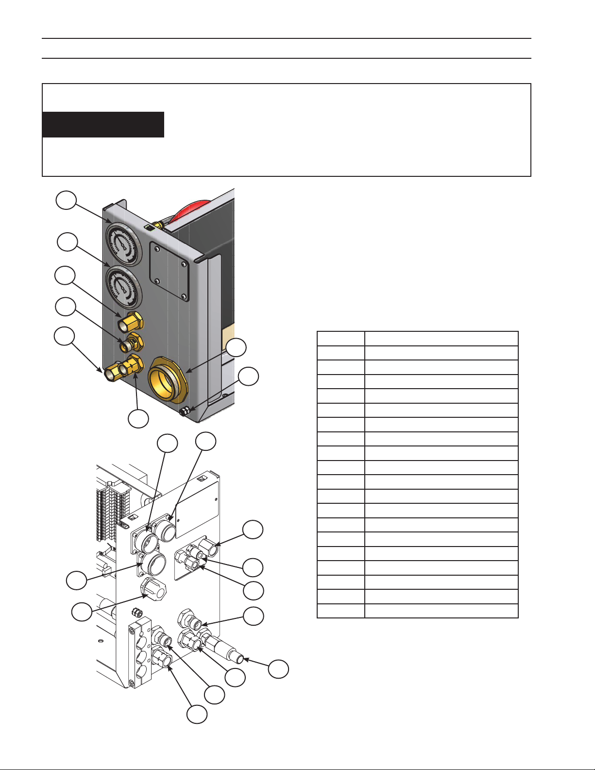
SECTION 3 INSTALLATION
Gas Line Contamination Will Damage Proportional Valves.
Purge Gas Lines.
CAUTION
1
2
5
6
Before connecting gas delivery lines to the m3 Plasma System
Plasma Gas Box, purge all lines thoroughly. Residue from the hose
manufacturing process may clog/damage the proportional valves in
your m3 Plasma System Plasma Gas Box.
1. Purge gas and air lines completely before connecting
to 25 micron gas lters.
2. Connect oxygen, H-35, nitrogen and air lines to gas
lters.
3. Purge gas/air lines between shield gas box and m3
Plasma System Plasma Gas Box.
4. Connect gas/air lines to back of Plasma Gas box.
4
7
20
3
8
10
12
11
9
13
19
15
1 PG1
2 PG2
3 Air Curtain
4 PG2 Out
5 PG1 Out
6 Shield
7 Tor ch
8 14 Pin To B3 Lifter
9 8 Pin to Shield Box
10 10 Pin To B3 Lifter
11 H-35
12 Start Gas Selection (O2 N2 AIR)
13 Argon
14 H2O IN
15 Shield
16 Air Curtain
17 Cut Gas Selection (O2 N2 AIR)
18 H2O OUT
19 LED Volt Meter
20 Torch Cable Leads Grounding stud
14
16
17
18
132

SECTION 3 INSTALLATION
.75”
19.1 mm
ELECTRICITY CAN KILL!
BEFORE PERFORMING ANY MAINTENANCE OR ASSEMBLY OF THIS
WARNING
3.6 Shield Gas Box Introduction
The m3 Plasma System Shield Gas Box interfaces with the ESAB Vision machine controls and the EPP product line
of plasma power sources. An interface pc board receives voltage signals from the machine CNC that control proportional and solenoid valves. The result is CNC management of gas or shield gas delivery to the plasma torch.
Analog signal feedback is sent back to the CNC, creating a control loop.
3.7 Shield Gas Box Mounting (Bottom View)
If mounting the box is required:
EQUIPMENT, ENSURE THE POWER SOURCE EPP IS TURNED OFF AND
DISCONNECTED.
The box has four (1.10”) 28 mm threaded mounting holes in a pattern oset from longitudinal center. Note relationship of hole pattern to gauges and cable clamp.
.75”
19.1 mm
6.50”
165.1 mm
1.50”
38.1 mm
back
front
16. 00”
406.4 mm
2.50”
63.5 mm
133

SECTION 3 INSTALLATION
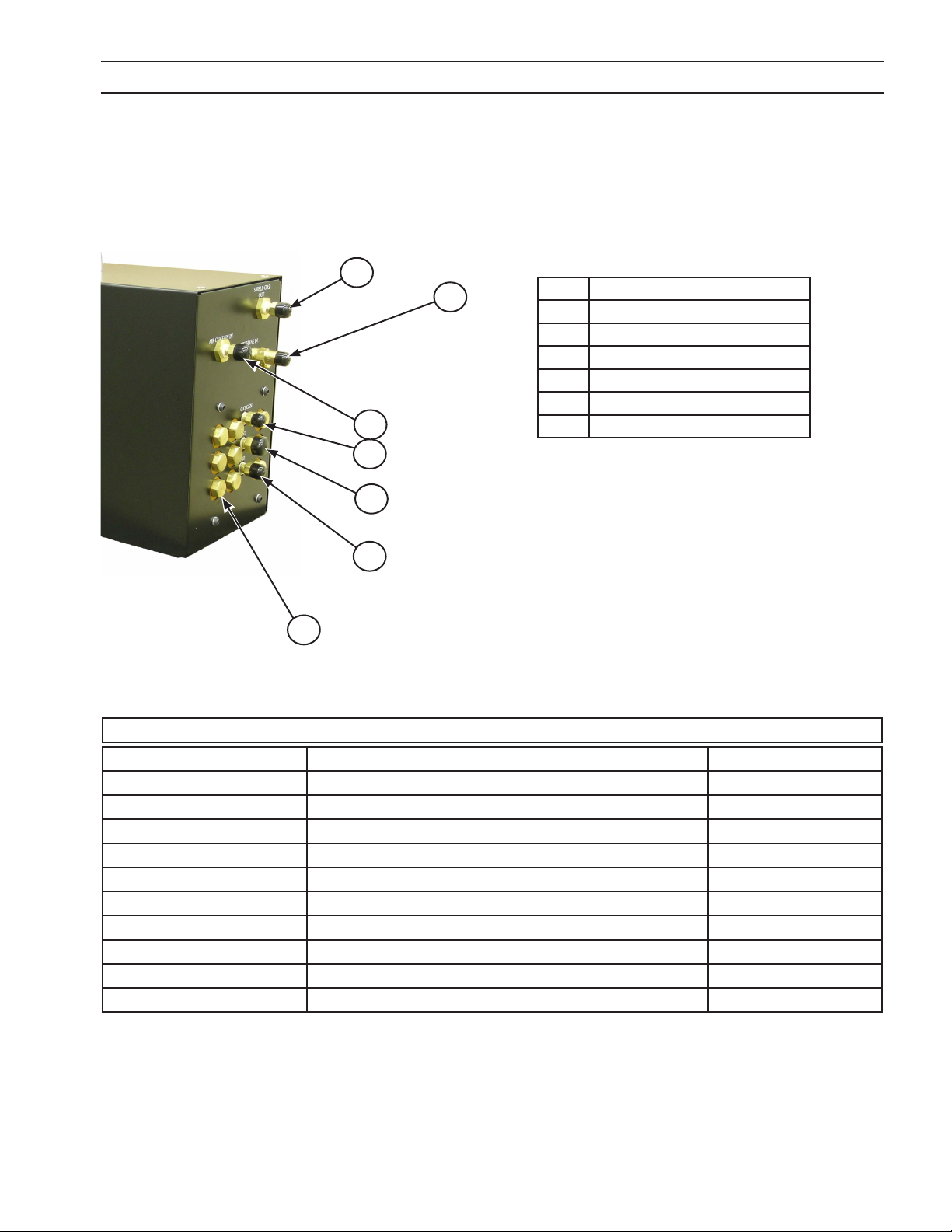
3.8 Shield Gas Box Connections
All connections are made on the exterior of the box. See diagrams and chart below.
Gas Line Contamination Will Damage Internal Components.
Purge Gas Lines.
CAUTION
3.8.1 Shield Gas Box front connections
4
5
6
Before connecting gas delivery lines to the m3 Plasma System Shield
Gas Box, purge all lines thoroughly. Residue from the hose manufacturing process may clog/damage the valves in your m3 Plasma
System Shield Gas Box.
1 Power Cable
13
10
12
1
11
2
2 Ground Connection
3 Buss Connection Communication
4 CNC Out to Power Source
5 To Plasma Gas Box
6 Spare
7 To Air Curtain
8 To Plasma Gas 2
9 To Plasma gas 1
10 Spare
11 Power Cable Connector
12 X100 Female Plug
13 Bracket
3
7
8
9
4
5
6
View from inside showing connections
of Items 4, 5 & 6
134
SECTION 3 INSTALLATION
3.8.2 Shield Gas Box rear connections
1
7
2
1 Shield Gas Out
2 Air Curtain Inlet
3 Oxygen Inlet
4 N2 Inlet
5 Air Inlet
6 Check Valves (typical)
7 CH4 Inlet
3
4
5
6
m3 Gas Fittings Kit (0558005229, included w/ m3 system) Consists of the following:
P/N Description Quantity
36Z40 NUT HOSE B-A/W .63-18F RH 2
136Z08 NUT HOSE B-I/G .63-18M RH 1
3380 NUT HOSE B-OXY .56-18F RH 1
3381 NUT HOSE B/ACET .56-18F LH 2
136Z07 NUT HOSE A-I/G .38-24M RH 1
2064114 NPL PUSH A/A-W 3/16 ID HOSE 1
03Z74 NPL PUSH B/SIZE 3/8 HOSE 5
3479 95 NPL PUSH B/A-W 3/8 ID HOSE 1
0558006336 m3 PLASMA FILTER ASSEMBLY 1
20373 FLASH ARRESTOR ASSEMBLY 1
135

SECTION 3 INSTALLATION
3.9 Component Relationship Block Diagram
3
5
4
Air
(clean,
dry, oil-
free shop
air for Air
Curtain
supply)
N
(plasma
2
Air
shield
supply
DIN
Qual-
ity ISO
8573-1)
CH
H-35
Argon
O
2
4
3-phase w/
ground
2
3a
1
Cable
CNC
Pilot Arc
Power Cable
13
PS & WC Control Cables
Cable 4c
Pair
Cable 4 Twisted
25 Micron lters
Note:
Air Curtain or Bubble Muer can
be used here. See torch manual for
conditions.
9
10
14
Power Cable
Pilot Arc Cable
11
7
8
6
16
12
LED Volt Meter
15a = 10 Pin
15b = 14 Pin
Torch Lead
Encoder / Voltage
Height Control
17
Workpiece
Earth Ground
Work Table
136

SECTION 3 INSTALLATION
ITEM NUMBER PART NUMBER DESCRIPTION
1 05 5800 4315 EPP-200, 200,230,380,415,460,575V
0558006470 EPP-400 400V, 50/60Hz CE
0558006471 EPP-400 460V, 60Hz
0558006472 EPP-400 575V, 60Hz
0558006473 EPP-600 400V, 50/60Hz CE
05 5800 6474 EPP-600 460V, 60Hz
0558006475 EPP-600 575V, 60Hz
0558007800 EPP-201, 380/400V, 50/60Hz, CCC/CE
0558007801 EPP-201, 460V, 60Hz
0558007802 EPP-201, 575V, 60Hz
0558007831 EPP-360, 380/400V, 50/60Hz, CCC/CE
0558006832 EPP-360, 460V, 60Hz
0558006833 EPP-360, 575V, 60Hz
0558007730 EPP-401/450, 380/400V, 50/60Hz CE
0558007731 EPP-450, 460V, 60Hz
0558007732 EPP-450, 575V, 60Hz
0558007733 EPP-601, 380/400V, 50/60Hz, CCC/CE
0558007734 EPP-601, 460V, 60Hz
0558007735 EPP-601, 575V, 60Hz
2 0558006086 Junction Box, PS & WC
3 0558004837 Cable Control, WC, 5m (16’)
0558004838 Cable Control, WC, 10m (33’)
0558004839 Cable Control, WC, 20m (66’)
3a 0558004849 Cable Control, PS & WC, 5m (16’)
0558004850 Cable Control, PS & WC, 10m (33’)
05580 04851 Cable Control, PS & WC, 20m (66’)
0558004852 Cable Control, PS & WC, 40m (131’)
0558004853 Cable Control, PS & WC, 50m (164’)
0558004854 Cable Control, PS & WC, 60m (196’)
0558005237 Cable Control, PS & WC, 15m (49’)
0558005238 Cable Control, PS & WC, 30m (98’)
4 0558005246 Coolant Hose, 5m (16’)
0558005563 Coolant Hose, 10m (33’)
0558005564 Coolant Hose, 15m (49’)
0558005565 Coolant Hose, 20m (66’)
0558005247 Coolant Hose, 30m (98’)
0558005248 Coolant Hose, 40m (131’)
0558005567 Coolant Hose, 50m (164’)
0558005249 Coolant Hose, 60m (196’)
137

SECTION 3 INSTALLATION
ITEM NUMBER PART NUMBER DESCRIPTION
5 0558004400 Coolant Circulator PCC-10
05 5800 7515 Coolant Circulator PCC-11
6 0558006089 Hose, Plasma Gas #1, 1.5m (5’)
0558006090 Hose, Plasma Gas #1, 5m (16’)
0558006091 Hose, Plasma Gas #1, 6m (19’)
0558006092 Hose, Plasma Gas #1, 7m (23’)
0558006093 Hose, Plasma Gas #1, 8m (26’)
0558006094 Hose, Plasma Gas #1, 9m (30’)
0558006095 Hose, Plasma Gas #1, 10m (33’)
0558006096 Hose, Plasma Gas #1, 11m (36’)
0558006097 Hose, Plasma Gas #1, 12m (39’)
0558006098 Hose, Plasma Gas #1, 13m (43’)
0558006099 Hose, Plasma Gas #1, 14m (46’)
0558006100 Hose, Plasma Gas #1, 15m (49’)
0558 006101 Hose, Plasma Gas #1, 16m (52’)
0558 006102 Hose, Plasma Gas #1, 17m (56’)
0558 006103 Hose, Plasma Gas #1, 18m (59’)
0558 006104 Hose, Plasma Gas #1, 19m (62’)
0558006105 Hose, Plasma Gas #1, 20m (66’)
7 0558006106 Hose, Plasma Gas #2, 1.5m (5’)
0558 006107 Hose, Plasma Gas #2, 5m (16’)
0558006108 Hose, Plasma Gas #2, 6m (19’)
0558 006109 Hose, Plasma Gas #2, 7m (23’)
0 55 8 0 0 6 110 Hose, Plasma Gas #2, 8m (26’)
0 55 8 0 0 6 111 Hose, Plasma Gas #2, 9m (30’)
0 55 8 0 0 6 112 Hose, Plasma Gas #2, 10m (33’)
0 55 8 0 0 6 113 Hose, Plasma Gas #2, 11m (36’)
0 55 8 0 0 6 114 Hose, Plasma Gas #2, 12m (39’)
0 55 8 0 0 6 115 Hose, Plasma Gas #2, 13m (43’)
0 55 8 0 0 6 116 Hose, Plasma Gas #2, 14m (46’)
0 55 8 0 0 6 117 Hose, Plasma Gas #2, 15m (49’)
0 55 8 0 0 6 118 Hose, Plasma Gas #2, 16m (52’)
0 55 8 0 0 6 119 Hose, Plasma Gas #2, 17m (56’)
05 58 00 612 0 Hose, Plasma Gas #2, 18m (59’)
05 58 00 6121 Hose, Plasma Gas #2, 19m (62’)
05 58 00 612 2 Hose, Plasma Gas #2, 20m (66’)
138

SECTION 3 INSTALLATION
ITEM NUMBER PART NUMBER DESCRIPTION
8 0558006200 Hose, Shield Gas, 1.5m (5’)
0558006201 Hose, Shield Gas, 5m (16’)
0558006202 Hose, Shield Gas, 6m (19’)
0558006203 Hose, Shield Gas, 7m (23’)
0558006204 Hose, Shield Gas, 8m (26’)
0558006205 Hose, Shield Gas, 9m (30’)
0558006206 Hose, Shield Gas, 10m (33’)
0558006207 Hose, Shield Gas, 11m (36’)
0558006208 Hose, Shield Gas, 12m (39’)
0558006209 Hose, Shield Gas, 13m (43’)
05580 06210 Hose, Shield Gas, 14m (46’)
0 55 8 0 0 6 211 Hose, Shield Gas, 15m (49’)
05 58 00 62 12 Hose, Shield Gas, 16m (52’)
05 58 00 6213 Hose, Shield Gas, 17m (56’)
0558 006214 Hose, Shield Gas, 18m (59’)
05 5800 6215 Hose, Shield Gas, 19m (62’)
055 800 6216 Hose, Shield Gas, 20m (66’)
9 05 58 0 06 217 Hose, Air Curtain, 1.5m (5’)
055 8006218 Hose, Air Curtain, 5m (16’)
0558 00 6219 Hose, Air Curtain, 6m (19’)
0558006865 Hose, Air Curtain, 6.1m (20’)
0558006220 Hose, Air Curtain, 7m (23’)
05580 06221 Hose, Air Curtain, 8m (26’)
0558006222 Hose, Air Curtain, 9m (30’)
0558006223 Hose, Air Curtain, 10m (33’)
0558006224 Hose, Air Curtain, 11m (36’)
0558006225 Hose, Air Curtain, 12m (39’)
0558006226 Hose, Air Curtain, 13m (43’)
0558006227 Hose, Air Curtain, 14m (46’)
0558006228 Hose, Air Curtain, 15m (49’)
0558006229 Hose, Air Curtain, 16m (52’)
0558006230 Hose, Air Curtain, 17m (56’)
055800 6231 Hose, Air Curtain, 18m (59’)
0558006232 Hose, Air Curtain, 19m (62’)
0558006233 Hose, Air Curtain, 20m (66’)
139

SECTION 3 INSTALLATION
ITEM NUMBER PART NUMBER DESCRIPTION
10 055 80 04 841 Air Curtain Hose 1.4m (4.5’)
0558004842 Air Curtain Hose 1.8m (6’)
0558004843 Air Curtain Hose 3.6m (12’)
0558004844 Air Curtain Hose 4.6m (15’)
0558004845 Air Curtain Hose 5.2m (17’)
0558004846 Air Curtain Hose 7.6m (25’)
11 056 09 42 312 Shield Gas Box
12 0560 9414 91 Plasma Gas Box
13 2239606 Power Junction Box
14 374 40 Air Curtain Assembly
37439 Bubble Muer
15a 05 609 40129 Cable, PGC-B3, 10p, 1.4m (4.5’) - 2 Plug
0 56 09 4170 0 Cable, PGC-B3, 10p, 1.8m (6’) - 2 Plug
05 60 94 0135 Cable, PGC-B3, 10p, 3.6m (12’) - 2 Plug
0 56 09 4170 1 Cable, PGC-B3, 10p, 4.6m (15’) - 2 Plug
0560940138 Cable, PGC-B3, 10p, 5.2m (17’) - 2 Plug
05 60 94 0141 Cable, PGC-B3, 10p, 7.6m (25’) - 2 Plug
05 6094 0142 Cable, PGC-B3, 10p, 10.7m (35’) - 2 Plug
05 60 9414 82 Cable, PGC-B3, 10p, 7.6m (25’) - 1 Plug
05 60 9414 83 Cable, PGC-B3, 10p, 10.7m (35’) - 1 Plug
05 60 9414 84 Cable, PGC-B3, 10p, 13.7m (45’) - 1 Plug
05 60 9414 85 Cable, PGC-B3, 10p, 16.8m (55’) - 1 Plug
140

SECTION 3 INSTALLATION
ITEM NUMBER PART NUMBER DESCRIPTION
15b 05 6094 0144 Cable, PGC-B3, 14p, 1.4m (4.5’) - 2 Plug
0 56 09 4170 2 Cable, PGC-B3, 14p, 1.8m (6’) - 2 Plug
05 6094 0147 Cable, PGC-B3, 14p, 3.6m (12’) - 2 Plug
0 56 09 4170 3 Cable, PGC-B3, 14p, 4.6m (15’) - 2 Plug
05 6094 0148 Cable, PGC-B3, 14p, 5.2m (17’) - 2 Plug
05 6094 0149 Cable, PGC-B3, 14p, 7.6m (25’) - 2 Plug
05 60 94 0152 Cable, PGC-B3, 14p, 10.7m (35’) - 2 Plug
05 60 9414 87 Cable, PGC-B3, 14p, 7.6m (25’) - 1 Plug
05 60 9414 88 Cable, PGC-B3, 14p, 10.7m (35’) - 1 Plug
05 60 9414 89 Cable, PGC-B3, 14p, 13.7m (45’) - 1 Plug
05 60 941490 Cable, PGC-B3, 14p, 16.8m (55’) - 1 Plug
16 0560939938 Cable, GS-PGC, 8p, 1.8m (6’)
0560939939 Cable, GS-PGC, 8p, 7.6m (25’)
0560939940 Cable, GS-PGC, 8p, 10.7m (35’)
05 60 939 941 Cable, GS-PGC, 8p, 13.7m (45’)
0560939942 Cable, GS-PGC, 8p, 16.8m (55’)
17 0558006745 Plasma Torch PT-36, 1.4m (4.5’)
0558006746 Plasma Torch PT-36, 1.8m (6’)
0558006747 Plasma Torch PT-36, 3.6m (12’)
0558006748 Plasma Torch PT-36 4.3m (14’)
0558006749 Plasma Torch PT-36, 4.6m (15’)
0558006750 Plasma Torch PT-36, 5.2m (17’)
0558006779 Plasma Torch PT-36, 6.1m (20’)
0558006751 Plasma Torch PT-36, 7.6m (25’)
141

SECTION 3 INSTALLATION
142

SECTION 4 OPERATION
4.0 Operation
4.1 Plasma Gas Box Operation
A major advantage of the m3 Plasma System Plasma Gas Box is that operating parameters are managed by the
machine CNC. There are no operating procedures necessary with the m3 Plasma System Plasma Gas Box. Management is accomplished either with manual inputs on the Vision cutting parameter screen or using the ESAB
system of Process Parameter Files.
Note:
Process Parameter Files (known by the acronyms … SDP or TDF) are les stored in the machine control
memory containing all necessary information for cutting a thickness and a material type. It is specic to
material, thickness, torch model, gas and material type. The information used to create the les can be
found in your torch manual. Refer to ESAB CNC Part Programming manual for more detail on the creation
and use of parameter les.
See CUT DATA MANUAL, P/N 0558006263 for cutting parameter set-
NOTICE
tings for using the m3 Plasma System Plasma Gas Box.
4.2 Plasma Gas Box Pressure Gauges
Pressure gauges display actual pressure to the torch. They provide visual feedback to the operator, and can be
helpful in spotting torch problems.
Note:
PG1 & PG2 are referred to as Start & Cut gas
Start Gas
(P G1)
Cut Gas
(PG2)
most of the time. Certain cutting conditions
require PG1 conditions only.
143

SECTION 4 OPERATION
4.3 Plasma Gas Box Pressure Switches
Pressure switches monitor line pressure and provide inputs to the CNC. If the pressure drops below 50 psi, the
CNC can shut the process down. Switches are in-line between the solenoid and the proportional valve for shield
gas 1 & 2, start gas and cut gas.
Plasma Gas Box
Gas Pressure Switch
144

SECTION 4 OPERATION
4.4 Shield Gas Box Operation
A major advantage of the m3 Plasma System Shield Gas Box is that operating parameters are managed by the
machine CNC. There are no operating procedures necessary with the m3 Plasma System Shield Gas Box. Management is accomplished either with manual inputs on the Vision cutting parameter screen or using the ESAB
system of Process Parameter Files.
Note:
Process Parameter Files (known by the acronyms … SDP or TDF) are les stored in the machine control
memory containing all necessary information for cutting a thickness and a material type. It is specic to
material, thickness, torch model, gas and material type. The information used to create the les can be
found in your torch manual. Refer to ESAB CNC Part Programming manual for more detail on the creation
and use of parameter les.
See CUT DATA MANUAL, P/N 0558006263 for cutting parameter set-
NOTICE
tings for using the m3 Plasma System Shield Gas Box.
145

SECTION 4 OPERATION
4.5 Shield Gas Box Air Regulator for Air Curtain
The Air Regulator displays actual air pressure to the torch.
It provides visual feedback to the operator, and can be
helpful in spotting torch problems.
To access the Air Regulator:
1. Remove the cover. No adjustment should be necessary
to the regulator. Regulator is factory set to 40 psi while
owing.
146

SECTION 4 OPERATION
4.6 Shield Gas Box Check Valves
Check Valves stop backow between gas selections. Periodic purging of check valves is necessary to clear gas
lines. To purge lines simply unscrew caps on check valves to bleed the gas pressure.
147
Check Valves
(9 typical)

SECTION 4 OPERATION
148
 Loading...