


Manual Gas Control Plasma System
PCC-14 Plumbing Box
Plasma Control Interface
Instruction Manual
This documentation is for ESAB equipment:
PCC-14 Plumbing Box part number 0558005840
Plasma Control Interface part number 0560948696 (serial #’s AA-K004001,002,003,004,005)
0558009614 05/2011

BE SURE THIS INFORMATION REACHES THE OPERATOR.
YOU CAN GET EXTRA COPIES THROUGH YOUR SUPPLIER.
CAUTION
These INSTRUCTIONS are for experienced operators. If you are not fully familiar with the
principles of operation and safe practices for arc welding and cutting equipment, we urge
you to read our booklet, “Precautions and Safe Practices for Arc Welding, Cutting, and
Gouging,” Form 52-529. Do NOT permit untrained persons to install, operate, or maintain
this equipment. Do NOT attempt to install or operate this equipment until you have read
and fully understand these instructions. If you do not fully understand these instructions,
contact your supplier for further information. Be sure to read the Safety Precautions before installing or operating this equipment.
USER RESPONSIBILITY
This equipment will perform in conformity with the description thereof contained in this manual and accompanying labels and/or inserts when installed, operated, maintained and repaired in accordance with the instructions provided. This equipment must be checked periodically. Malfunctioning or poorly maintained equipment
should not be used. Parts that are broken, missing, worn, distorted or contaminated should be replaced immediately. Should such repair or replacement become necessary, the manufacturer recommends that a telephone
or written request for service advice be made to the Authorized Distributor from whom it was purchased.
This equipment or any of its parts should not be altered without the prior written approval of the manufacturer.
The user of this equipment shall have the sole responsibility for any malfunction which results from improper
use, faulty maintenance, damage, improper repair or alteration by anyone other than the manufacturer or a service facility designated by the manufacturer.
READ AND UNDERSTAND THE INSTRUCTION MANUAL BEFORE INSTALLING OR OPERATING.
PROTECT YOURSELF AND OTHERS!

TABLE OF CONTENTS
Section / Title Page
1.0 Safety Precautions. . . . . . . . . . . . . . . . . . . . . . . . . . . . . . . . . . . . . . . . . . . . . . . . . . . . . . . . . . . . . . . . . . . . . . . . . . . . . . . . . . . . . . . . . . . . . . . . . . . . . . . . . . . 5
1.1 Safety - English . . . . . . . . . . . . . . . . . . . . . . . . . . . . . . . . . . . . . . . . . . . . . . . . . . . . . . . . . . . . . . . . . . . . . . . . . . . . . . . . . . . . . . . . . . . . . . . . . . . . . . 5
1.2 Safety - Spanish . . . . . . . . . . . . . . . . . . . . . . . . . . . . . . . . . . . . . . . . . . . . . . . . . . . . . . . . . . . . . . . . . . . . . . . . . . . . . . . . . . . . . . . . . . . . . . . . . . . . . . 9
1.3 Safety - French . . . . . . . . . . . . . . . . . . . . . . . . . . . . . . . . . . . . . . . . . . . . . . . . . . . . . . . . . . . . . . . . . . . . . . . . . . . . . . . . . . . . . . . . . . . . . . . . . . . . . .13
2.0 ESAB m3 Manual Gas Control System. . . . . . . . . . . . . . . . . . . . . . . . . . . . . . . . . . . . . . . . . . . . . . . . . . . . . . . . . . . . . . . . . . . . . . . . . . . . . . . . . . . . . . . . 17
PCC-14 Plumbing Box . . . . . . . . . . . . . . . . . . . . . . . . . . . . . . . . . . . . . . . . . . . . . . . . . . . . . . . . . . . . . . . . . . . . . . . . . . . . . . . . . . . . . . . . . . . . . . . . . . . . . . . . . . . . . .19
3.0 General . . . . . . . . . . . . . . . . . . . . . . . . . . . . . . . . . . . . . . . . . . . . . . . . . . . . . . . . . . . . . . . . . . . . . . . . . . . . . . . . . . . . . . . . . . . . . . . . . . . . . . . . . . . . . . . . . . . . . . 21
3.1 Scope. . . . . . . . . . . . . . . . . . . . . . . . . . . . . . . . . . . . . . . . . . . . . . . . . . . . . . . . . . . . . . . . . . . . . . . . . . . . . . . . . . . . . . . . . . . . . . . . . . . . . . . . . . . . . . . 21
3.2 Plumbing Box Spark Gap Adjustment. . . . . . . . . . . . . . . . . . . . . . . . . . . . . . . . . . . . . . . . . . . . . . . . . . . . . . . . . . . . . . . . . . . . . . . . . . . . . . . . 24
3.3 Plumbing Box Connections. . . . . . . . . . . . . . . . . . . . . . . . . . . . . . . . . . . . . . . . . . . . . . . . . . . . . . . . . . . . . . . . . . . . . . . . . . . . . . . . . . . . . . . . . . 25
3.4 EPP-201 / EPP-360 Torch Connections to Plumbing Box. . . . . . . . . . . . . . . . . . . . . . . . . . . . . . . . . . . . . . . . . . . . . . . . . . . . . . . . . . . . . . . 27
3.5 PCC-14 Plumbing Box Mounting Hole Locations. . . . . . . . . . . . . . . . . . . . . . . . . . . . . . . . . . . . . . . . . . . . . . . . . . . . . . . . . . . . . . . . . . . . . . 29
Plasma Control Interface. . . . . . . . . . . . . . . . . . . . . . . . . . . . . . . . . . . . . . . . . . . . . . . . . . . . . . . . . . . . . . . . . . . . . . . . . . . . . . . . . . . . . . . . . . . . . . . . . . . . . . . . . . .31
3.6 General . . . . . . . . . . . . . . . . . . . . . . . . . . . . . . . . . . . . . . . . . . . . . . . . . . . . . . . . . . . . . . . . . . . . . . . . . . . . . . . . . . . . . . . . . . . . . . . . . . . . . . . . . . . . . . . . . . .33
3.7 Scope. . . . . . . . . . . . . . . . . . . . . . . . . . . . . . . . . . . . . . . . . . . . . . . . . . . . . . . . . . . . . . . . . . . . . . . . . . . . . . . . . . . . . . . . . . . . . . . . . . . . . . . . . . . . . . . 33
3.8 Plasma Control Interface Connections . . . . . . . . . . . . . . . . . . . . . . . . . . . . . . . . . . . . . . . . . . . . . . . . . . . . . . . . . . . . . . . . . . . . . . . . . . . . . . .34
3.9 Typical / Recommended E-stop Connection . . . . . . . . . . . . . . . . . . . . . . . . . . . . . . . . . . . . . . . . . . . . . . . . . . . . . . . . . . . . . . . . . . . . . . . . .37
3.10 Control Sequence . . . . . . . . . . . . . . . . . . . . . . . . . . . . . . . . . . . . . . . . . . . . . . . . . . . . . . . . . . . . . . . . . . . . . . . . . . . . . . . . . . . . . . . . . . . . . . . . . . .38
3.11 Plasma Control Interface Mounting Hole Locations . . . . . . . . . . . . . . . . . . . . . . . . . . . . . . . . . . . . . . . . . . . . . . . . . . . . . . . . . . . . . . . . . .39
3.12 Plasma Control Interface STATUS Codes. . . . . . . . . . . . . . . . . . . . . . . . . . . . . . . . . . . . . . . . . . . . . . . . . . . . . . . . . . . . . . . . . . . . . . . . . . . . . .40
4.0 Maintenance . . . . . . . . . . . . . . . . . . . . . . . . . . . . . . . . . . . . . . . . . . . . . . . . . . . . . . . . . . . . . . . . . . . . . . . . . . . . . . . . . . . . . . . . . . . . . . . . . . . . . . . . . . . . . . . 41
4.1 General . . . . . . . . . . . . . . . . . . . . . . . . . . . . . . . . . . . . . . . . . . . . . . . . . . . . . . . . . . . . . . . . . . . . . . . . . . . . . . . . . . . . . . . . . . . . . . . . . . . . . . . . . . . . .41
4.2 Cleaning . . . . . . . . . . . . . . . . . . . . . . . . . . . . . . . . . . . . . . . . . . . . . . . . . . . . . . . . . . . . . . . . . . . . . . . . . . . . . . . . . . . . . . . . . . . . . . . . . . . . . . . . . . . .41
5.0 Marking Module . . . . . . . . . . . . . . . . . . . . . . . . . . . . . . . . . . . . . . . . . . . . . . . . . . . . . . . . . . . . . . . . . . . . . . . . . . . . . . . . . . . . . . . . . . . . . . . . . . . . . . . . . . . .43
5.1 Marking Module Mounting Hole Locations . . . . . . . . . . . . . . . . . . . . . . . . . . . . . . . . . . . . . . . . . . . . . . . . . . . . . . . . . . . . . . . . . . . . . . . . . .44
6.0 PT-36R Plasma Torch . . . . . . . . . . . . . . . . . . . . . . . . . . . . . . . . . . . . . . . . . . . . . . . . . . . . . . . . . . . . . . . . . . . . . . . . . . . . . . . . . . . . . . . . . . . . . . . . . . . . . . . .45
6.1 PT-36R Technical Specications. . . . . . . . . . . . . . . . . . . . . . . . . . . . . . . . . . . . . . . . . . . . . . . . . . . . . . . . . . . . . . . . . . . . . . . . . . . . . . . . . . . . . .46
6.2 Gas Specications. . . . . . . . . . . . . . . . . . . . . . . . . . . . . . . . . . . . . . . . . . . . . . . . . . . . . . . . . . . . . . . . . . . . . . . . . . . . . . . . . . . . . . . . . . . . . . . . . . .46
6.3 Recommended Regulators . . . . . . . . . . . . . . . . . . . . . . . . . . . . . . . . . . . . . . . . . . . . . . . . . . . . . . . . . . . . . . . . . . . . . . . . . . . . . . . . . . . . . . . . . .47
6.4 PT-36R Torch Technical Specications. . . . . . . . . . . . . . . . . . . . . . . . . . . . . . . . . . . . . . . . . . . . . . . . . . . . . . . . . . . . . . . . . . . . . . . . . . . . . . . . 47
7.0 Coolant Circulator . . . . . . . . . . . . . . . . . . . . . . . . . . . . . . . . . . . . . . . . . . . . . . . . . . . . . . . . . . . . . . . . . . . . . . . . . . . . . . . . . . . . . . . . . . . . . . . . . . . . . . . . . .49
7.1 Specications . . . . . . . . . . . . . . . . . . . . . . . . . . . . . . . . . . . . . . . . . . . . . . . . . . . . . . . . . . . . . . . . . . . . . . . . . . . . . . . . . . . . . . . . . . . . . . . . . . . . . . .50
7.2 Installation. . . . . . . . . . . . . . . . . . . . . . . . . . . . . . . . . . . . . . . . . . . . . . . . . . . . . . . . . . . . . . . . . . . . . . . . . . . . . . . . . . . . . . . . . . . . . . . . . . . . . . . . . . 51
7.3 Input Power Connections . . . . . . . . . . . . . . . . . . . . . . . . . . . . . . . . . . . . . . . . . . . . . . . . . . . . . . . . . . . . . . . . . . . . . . . . . . . . . . . . . . . . . . . . . . .52
8.0 EPP-201 Power Supply . . . . . . . . . . . . . . . . . . . . . . . . . . . . . . . . . . . . . . . . . . . . . . . . . . . . . . . . . . . . . . . . . . . . . . . . . . . . . . . . . . . . . . . . . . . . . . . . . . . . . .55
8.1 Dimensions and Weight . . . . . . . . . . . . . . . . . . . . . . . . . . . . . . . . . . . . . . . . . . . . . . . . . . . . . . . . . . . . . . . . . . . . . . . . . . . . . . . . . . . . . . . . . . . . .56
8.2 Input Power Connection . . . . . . . . . . . . . . . . . . . . . . . . . . . . . . . . . . . . . . . . . . . . . . . . . . . . . . . . . . . . . . . . . . . . . . . . . . . . . . . . . . . . . . . . . . . .57
9.0 EPP-360 Power Supply . . . . . . . . . . . . . . . . . . . . . . . . . . . . . . . . . . . . . . . . . . . . . . . . . . . . . . . . . . . . . . . . . . . . . . . . . . . . . . . . . . . . . . . . . . . . . . . . . . . . . .59
9.1 Dimensions and Weight . . . . . . . . . . . . . . . . . . . . . . . . . . . . . . . . . . . . . . . . . . . . . . . . . . . . . . . . . . . . . . . . . . . . . . . . . . . . . . . . . . . . . . . . . . . . .60
9.2 Input Power Connection . . . . . . . . . . . . . . . . . . . . . . . . . . . . . . . . . . . . . . . . . . . . . . . . . . . . . . . . . . . . . . . . . . . . . . . . . . . . . . . . . . . . . . . . . . . .61

TABLE OF CONTENTS
10.0 HOSES AND CABLES . . . . . . . . . . . . . . . . . . . . . . . . . . . . . . . . . . . . . . . . . . . . . . . . . . . . . . . . . . . . . . . . . . . . . . . . . . . . . . . . . . . . . . . . . . . . . . . . . . . . . . . .63
10.1 Hoses. . . . . . . . . . . . . . . . . . . . . . . . . . . . . . . . . . . . . . . . . . . . . . . . . . . . . . . . . . . . . . . . . . . . . . . . . . . . . . . . . . . . . . . . . . . . . . . . . . . . . . . . . . . . . . .63
10.2 Cables. . . . . . . . . . . . . . . . . . . . . . . . . . . . . . . . . . . . . . . . . . . . . . . . . . . . . . . . . . . . . . . . . . . . . . . . . . . . . . . . . . . . . . . . . . . . . . . . . . . . . . . . . . . . . . . . .68
11.0 Replacement Parts. . . . . . . . . . . . . . . . . . . . . . . . . . . . . . . . . . . . . . . . . . . . . . . . . . . . . . . . . . . . . . . . . . . . . . . . . . . . . . . . . . . . . . . . . . . . . . . . . . . . . . . . . . 71
11.1 General . . . . . . . . . . . . . . . . . . . . . . . . . . . . . . . . . . . . . . . . . . . . . . . . . . . . . . . . . . . . . . . . . . . . . . . . . . . . . . . . . . . . . . . . . . . . . . . . . . . . . . . . . . . . .71
11.2 Ordering. . . . . . . . . . . . . . . . . . . . . . . . . . . . . . . . . . . . . . . . . . . . . . . . . . . . . . . . . . . . . . . . . . . . . . . . . . . . . . . . . . . . . . . . . . . . . . . . . . . . . . . . . . . .71
Diagrams and Parts List . . . . . . . . . . . . . . . . . . . . . . . . . . . . . . . . . . . . . . . . . . . . . . . . . . . . . . . . . . . . . . . . . . . . . . . . . . . . . . . . . . . . . . . attached packet
4

SECTION 1 SAFETY PRECAUTIONS
1.0 Safety Precautions
WARNING: These Safety Precautions are
for your protection. They summarize precautionary information from the references
listed in Additional Safety Information section. Before performing any installation or operating
procedures, be sure to read and follow the safety precautions listed below as well as all other manuals, material
safety data sheets, labels, etc. Failure to observe Safety
Precautions can result in injury or death.
PROTECT YOURSELF AND OTHERS -Some welding, cutting, and gouging
processes are noisy and require ear
protection. The arc, like the sun, emits
ultraviolet (UV) and other radiation
and can injure skin and eyes. Hot metal can cause
burns. Training in the proper use of the processes
and equipment is essential to prevent accidents.
Therefore:
1. Always wear safety glasses with side shields in any
work area, even if welding helmets, face shields, and
goggles are also required.
2. Use a face shield tted with the correct lter and
cover plates to protect your eyes, face, neck, and
ears from sparks and rays of the arc when operating
or observing operations. Warn bystanders not to
watch the arc and not to expose themselves to the
rays of the electric-arc or hot metal.
3. Wear ameproof gauntlet type gloves, heavy long-
sleeve shirt, cuess trousers, high-topped shoes,
and a welding helmet or cap for hair protection, to
protect against arc rays and hot sparks or hot metal.
A ameproof apron may also be desirable as protection against radiated heat and sparks.
4. Hot sparks or metal can lodge in rolled up sleeves,
trouser cus, or pockets. Sleeves and collars should
be kept buttoned, and open pockets eliminated from
the front of clothing.
5. Protect other personnel from arc rays and hot
sparks with a suitable non-ammable partition or
curtains.
6. Use goggles over safety glasses when chipping slag
or grinding. Chipped slag may be hot and can y far.
Bystanders should also wear goggles over safety
glasses.
1.1 Safety - English
FIRES AND EXPLOSIONS -- Heat from
ames and arcs can start res. Hot
slag or sparks can also cause res and
explosions. Therefore:
1. Remove all combustible materials well away from
the work area or cover the materials with a protective non-ammable covering. Combustible materials
include wood, cloth, sawdust, liquid and gas fuels,
solvents, paints and coatings, paper, etc.
2. Hot sparks or hot metal can fall through cracks or
crevices in oors or wall openings and cause a hidden smoldering re or res on the oor below. Make
certain that such openings are protected from hot
sparks and metal.“
3. Do not weld, cut or perform other hot work until the
workpiece has been completely cleaned so that there
are no substances on the workpiece which might
produce ammable or toxic vapors. Do not do hot
work on closed containers. They may explode.
4. Have re extinguishing equipment handy for instant
use, such as a garden hose, water pail, sand bucket,
or portable re extinguisher. Be sure you are trained
in its use.
5. Do not use equipment beyond its ratings. For example, overloaded welding cable can overheat and
create a re hazard.
6. After completing operations, inspect the work area
to make certain there are no hot sparks or hot metal
which could cause a later re. Use re watchers when
necessary.
7. For additional information, refer to NFPA Standard
51B, "Fire Prevention in Use of Cutting and Welding
Processes", available from the National Fire Protection Association, Batterymarch Park, Quincy, MA
02269.
ELECTRICAL SHOCK -- Contact with
live electrical parts and ground can
cause severe injury or death. DO NOT
use AC welding current in damp areas,
if movement is conned, or if there is
danger of falling.
5

SECTION 1 SAFETY PRECAUTIONS
1. Be sure the power source frame (chassis) is connected to the ground system of the input power.
2. Connect the workpiece to a good electrical
ground.
3. Connect the work cable to the workpiece. A poor
or missing connection can expose you or others
to a fatal shock.
4. Use well-maintained equipment. Replace worn or
damaged cables.
5. Keep everything dry, including clothing, work
area, cables, torch/electrode holder, and power
source.
6. Make sure that all parts of your body are insulated
from work and from ground.
7. Do not stand directly on metal or the earth while
working in tight quarters or a damp area; stand
on dry boards or an insulating platform and wear
rubber-soled shoes.
8. Put on dry, hole-free gloves before turning on the
power.
3. Welders should use the following procedures to
minimize exposure to EMF:
A. Route the electrode and work cables together.
Secure them with tape when possible.
B. Never coil the torch or work cable around your
body.
C. Do not place your body between the torch and
work cables. Route cables on the same side of
your body.
D. Connect the work cable to the workpiece as close
as possible to the area being welded.
E. Keep welding power source and cables as far
away from your body as possible.
FUMES AND GASES -- Fumes and
gases, can cause discomfort or harm,
particularly in conned spaces. Do
not breathe fumes and gases. Shielding gases can cause asphyxiation.
Therefore:
9. Turn o the power before removing your gloves.
10. Refer to ANSI/ASC Standard Z49.1 (listed on
next page) for specic grounding recommendations. Do not mistake the work lead for a ground
cable.
ELECTRIC AND MAGNETIC FIELDS
— May be dangerous. Electric current owing through any conductor causes localized Electric and
Magnetic Fields (EMF). Welding and
cutting current creates EMF around welding cables
and welding machines. Therefore:
1. Welders having pacemakers should consult their
physician before welding. EMF may interfere with
some pacemakers.
2. Exposure to EMF may have other health eects which
are unknown.
1. Always provide adequate ventilation in the work area
by natural or mechanical means. Do not weld, cut, or
gouge on materials such as galvanized steel, stainless steel, copper, zinc, lead, beryllium, or cadmium
unless positive mechanical ventilation is provided.
Do not breathe fumes from these materials.
2. Do not operate near degreasing and spraying operations. The heat or arc rays can react with chlorinated
hydrocarbon vapors to form phosgene, a highly
toxic gas, and other irritant gases.
3. If you develop momentary eye, nose, or throat irritation while operating, this is an indication that
ventilation is not adequate. Stop work and take
necessary steps to improve ventilation in the work
area. Do not continue to operate if physical discomfort persists.
4. Refer to ANSI/ASC Standard Z49.1 (see listing below)
for specic ventilation recommendations.
6

SECTION 1 SAFETY PRECAUTIONS
5. WARNING: This product, when used for welding
or cutting, produces fumes or gases
which contain chemicals known to
the State of California to cause birth
defects and, in some cases, cancer.
(California Health & Safety Code
§25249.5 et seq.)
CYLINDER HANDLING -- Cylinders,
if mishandled, can rupture and violently release gas. Sudden rupture
of cylinder, valve, or relief device can
injure or kill. Therefore:
1. Use the proper gas for the process and use the
proper pressure reducing regulator designed to
operate from the compressed gas cylinder. Do not
use adaptors. Maintain hoses and ttings in good
condition. Follow manufacturer's operating instructions for mounting regulator to a compressed gas
cylinder.
1. Always have qualied personnel perform the installation, troubleshooting, and maintenance work.
Do not perform any electrical work unless you are
qualied to perform such work.
2. Before performing any maintenance work inside a
power source, disconnect the power source from
the incoming electrical power.
3. Maintain cables, grounding wire, connections, power
cord, and power supply in safe working order. Do
not operate any equipment in faulty condition.
4. Do not abuse any equipment or accessories. Keep
equipment away from heat sources such as furnaces,
wet conditions such as water puddles, oil or grease,
corrosive atmospheres and inclement weather.
5. Keep all safety devices and cabinet covers in position
and in good repair.
6. Use equipment only for its intended purpose. Do
not modify it in any manner.
2. Always secure cylinders in an upright position by
chain or strap to suitable hand trucks, undercarriages, benches, walls, post, or racks. Never secure
cylinders to work tables or xtures where they may
become part of an electrical circuit.
3. When not in use, keep cylinder valves closed. Have
valve protection cap in place if regulator is not connected. Secure and move cylinders by using suitable
hand trucks. Avoid rough handling of cylinders.
4. Locate cylinders away from heat, sparks, and ames.
Never strike an arc on a cylinder.
5. For additional information, refer to CGA Standard P-1,
"Precautions for Safe Handling of Compressed Gases
in Cylinders", which is available from Compressed
Gas Association, 1235 Jeerson Davis Highway,
Arlington, VA 22202.
EQUIPMENT MAINTENANCE -- Faulty or
improperly maintained equipment can
cause injury or death. Therefore:
ADDITIONAL SAFETY INFORMATION -- For
more information on safe practices for
electric arc welding and cutting equipment, ask your supplier for a copy of
"Precautions and Safe Practices for Arc
Welding, Cutting and Gouging", Form
52-529.
The following publications, which are available from
the American Welding Society, 550 N.W. LeJuene Road,
Miami, FL 33126, are recommended to you:
1. ANSI/ASC Z49.1 - "Safety in Welding and Cutting"
2. AWS C5.1 - "Recommended Practices for Plasma Arc
Welding"
3. AWS C5.2 - "Recommended Practices for Plasma Arc
Cutting"
4. AWS C5.3 - "Recommended Practices for Air Carbon
Arc Gouging and Cutting"
7

SECTION 1 SAFETY PRECAUTIONS
5. AWS C5.5 - "Recommended Practices for Gas Tungsten Arc Welding“
6. AWS C5.6 - "Recommended Practices for Gas Metal
Arc Welding"“
7. AWS SP - "Safe Practices" - Reprint, Welding Handbook.
8. ANSI/AWS F4.1, "Recommended Safe Practices for
Welding and Cutting of Containers That Have Held
Hazardous Substances."
MEANING OF SYMBOLS - As used
throughout this manual: Means Attention! Be Alert! Your safety is involved.
Means immediate hazards which,
if not avoided, will result in immediate, serious personal injury
or loss of life.
Means potential hazards which
could result in personal injury or
loss of life.
Means hazards which could result
in minor personal injury.
8

SECCION 1 SEGURIDAD
1.2 Safety - Spanish
ADVERTENCIA: Estas Precauciones de Se-
guridad son para su protección. Ellas hacen
resumen de información proveniente de las
referencias listadas en la sección "Información Adicional Sobre La Seguridad". Antes de hacer cualquier
instalación o procedimiento de operación , asegúrese
de leer y seguir las precauciones de seguridad listadas
a continuación así como también todo manual, hoja
de datos de seguridad del material, calcomanias, etc.
El no observar las Precauciones de Seguridad puede
resultar en daño a la persona o muerte.
PROTEJASE USTED Y A LOS DEMAS-Algunos procesos de soldadura, corte
y ranurado son ruidosos y requiren
protección para los oídos. El arco,
como el sol , emite rayos ultravioleta
(UV) y otras radiaciones que pueden dañar la piel
y los ojos. El metal caliente causa quemaduras. EL
entrenamiento en el uso propio de los equipos y
sus procesos es esencial para prevenir accidentes.
Por lo tanto:
1. Utilice gafas de seguridad con protección a los lados
siempre que esté en el área de trabajo, aún cuando
esté usando careta de soldar, protector para su cara
u otro tipo de protección.
2. Use una careta que tenga el ltro correcto y lente
para proteger sus ojos, cara, cuello, y oídos de las
chispas y rayos del arco cuando se esté operando y
observando las operaciones. Alerte a todas las personas cercanas de no mirar el arco y no exponerse
a los rayos del arco eléctrico o el metal fundido.
3. Use guantes de cuero a prueba de fuego, camisa
pesada de mangas largas, pantalón de ruedo liso,
zapato alto al tobillo, y careta de soldar con capucha
para el pelo, para proteger el cuerpo de los rayos y
chispas calientes provenientes del metal fundido.
En ocaciones un delantal a prueba de fuego es
necesario para protegerse del calor radiado y las
chispas.
4. Chispas y partículas de metal caliente puede alojarse
en las mangas enrolladas de la camisa , el ruedo del
pantalón o los bolsillos. Mangas y cuellos deberán
mantenerse abotonados, bolsillos al frente de la
camisa deberán ser cerrados o eliminados.
5. Proteja a otras personas de los rayos del arco y chis-
pas calientes con una cortina adecuada no-amable
como división.
6. Use careta protectora además de sus gafas de segu-
ridad cuando esté removiendo escoria o puliendo.
La escoria puede estar caliente y desprenderse con
velocidad. Personas cercanas deberán usar gafas
de seguridad y careta protectora.
FUEGO Y EXPLOSIONES -- El calor de
las amas y el arco pueden ocacionar
fuegos. Escoria caliente y las chispas
pueden causar fuegos y explosiones.
Por lo tanto:
1. Remueva todo material combustible lejos del área
de trabajo o cubra los materiales con una cobija a
prueba de fuego. Materiales combustibles incluyen
madera, ropa, líquidos y gases amables, solventes,
pinturas, papel, etc.
2. Chispas y partículas de metal pueden introducirse en
las grietas y agujeros de pisos y paredes causando
fuegos escondidos en otros niveles o espacios.
Asegúrese de que toda grieta y agujero esté cubierto
para proteger lugares adyacentes contra fuegos.
3. No corte, suelde o haga cualquier otro trabajo
relacionado hasta que la pieza de trabajo esté totalmente limpia y libre de substancias que puedan
producir gases inamables o vapores tóxicos. No
trabaje dentro o fuera de contenedores o tanques
cerrados. Estos pueden explotar si contienen vapores
inamables.
4. Tenga siempre a la mano equipo extintor de fuego para uso instantáneo, como por ejemplo una
manguera con agua, cubeta con agua, cubeta con
arena, o extintor portátil. Asegúrese que usted esta
entrenado para su uso.
5. No use el equipo fuera de su rango de operación. Por
ejemplo, el calor causado por cable sobrecarga en
los cables de soldar pueden ocasionar un fuego.
6. Después de termirar la operación del equipo, inspeccione el área de trabajo para cerciorarse de que las
chispas o metal caliente ocasionen un fuego más
tarde. Tenga personal asignado para vigilar si es
necesario.
7. Para información adicional , haga referencia a la
publicación NFPA Standard 51B, "Fire Prevention in
Use of Cutting and Welding Processes", disponible
a través de la National Fire Protection Association,
Batterymarch Park, Quincy, MA 02269.
CHOQUE ELECTRICO -- El contacto
con las partes eléctricas energizadas
y tierra puede causar daño severo o
muerte. NO use soldadura de corri-
ente alterna (AC) en áreas húmedas,
de movimiento connado en lugares estrechos o
si hay posibilidad de caer al suelo.
9

SECCION 1 SEGURIDAD
1. Asegúrese de que el chasis de la fuente de poder
esté conectado a tierra através del sistema de
electricidad primario.
2. Conecte la pieza de trabajo a un buen sistema de
tierra física.
3. Conecte el cable de retorno a la pieza de trabajo.
Cables y conductores expuestos o con malas
conexiones pueden exponer al operador u otras
personas a un choque eléctrico fatal.
4. Use el equipo solamente si está en buenas condiciones. Reemplaze cables rotos, dañados o con
conductores expuestos.
5. Mantenga todo seco, incluyendo su ropa, el área de
trabajo, los cables, antorchas, pinza del electrodo,
y la fuente de poder.
6. Asegúrese que todas las partes de su cuerpo están
insuladas de ambos, la pieza de trabajo y tierra.
7. No se pare directamente sobre metal o tierra mientras trabaja en lugares estrechos o áreas húmedas;
trabaje sobre un pedazo de madera seco o una
plataforma insulada y use zapatos con suela de
goma.
8. Use guantes secos y sin agujeros antes de energizar
el equipo.
9. Apage el equipo antes de quitarse sus guantes.
10. Use como referencia la publicación ANSI/ASC
Standard Z49.1 (listado en la próxima página) para
recomendaciones especícas de como conectar el
equipo a tierra. No confunda el cable de soldar a
la pieza de trabajo con el cable a tierra.
CAMPOS ELECTRICOS Y MAGNETICOS - Son peligrosos. La corriente
eléctrica uye através de cualquier
conductor causando a nivel local
Campos Eléctricos y Magnéticos
(EMF). Las corrientes en el área de corte y soldadura,
crean EMF alrrededor de los cables de soldar y las
maquinas. Por lo tanto:
1. Soldadores u Operadores que use marca-pasos para
el corazón deberán consultar a su médico antes de
soldar. El Campo Electromagnético (EMF) puede
interferir con algunos marca-pasos.
2. Exponerse a campos electromagnéticos (EMF) puede
causar otros efectos de salud aún desconocidos.
3. Los soldadores deberán usar los siguientes procedimientos para minimizar exponerse al EMF:
A. Mantenga el electrodo y el cable a la pieza de
trabajo juntos, hasta llegar a la pieza que usted
quiere soldar. Asegúrelos uno junto al otro con
cinta adhesiva cuando sea posible.
B. Nunca envuelva los cables de soldar alrededor
de su cuerpo.
C. Nunca ubique su cuerpo entre la antorcha y el
cable, a la pieza de trabajo. Mantega los cables a
un sólo lado de su cuerpo.
D. Conecte el cable de trabajo a la pieza de trabajo
lo más cercano posible al área de la soldadura.
E. Mantenga la fuente de poder y los cables de soldar
lo más lejos posible de su cuerpo.
HUMO Y GASES -- El humo y los
gases, pueden causar malestar o
daño, particularmente en espacios
sin ventilación. No inhale el humo
o gases. El gas de protección puede
causar falta de oxígeno.
Por lo tanto:
1. Siempre provea ventilación adecuada en el área
de trabajo por medio natural o mecánico. No solde,
corte, o ranure materiales con hierro galvanizado,
acero inoxidable, cobre, zinc, plomo, berílio, o cadmio a menos que provea ventilación mecánica
positiva . No respire los gases producidos por
estos materiales.
2. No opere cerca de lugares donde se aplique sub-
stancias químicas en aerosol. El calor de los rayos
del arco pueden reaccionar con los vapores de
hidrocarburo clorinado para formar un fosfógeno,
o gas tóxico, y otros irritant es.
3. Si momentáneamente desarrolla inrritación de
ojos, nariz o garganta mientras est á operando, es
indicación de que la ventilación no es apropiada.
Pare de trabajar y tome las medidas necesarias
para mejorar la ventilación en el área de trabajo.
No continúe operando si el malestar físico persiste.
4. Haga referencia a la publicación ANSI/ASC Standard
Z49.1 (Vea la lista a continuación) para recomendaciones especícas en la ventilación.
10

SECCION 1 SEGURIDAD
5. ADVERTENCIA-- Este producto cuando se utiliza para soldaduras o cortes,
produce humos o gases, los
cuales contienen químicos
conocidos por el Estado de California de causar defectos en el
nacimiento, o en algunos casos,
Cancer. (California Health &
Safety Code §25249.5 et seq.)
MANEJO DE CILINDROS-- Los
cilindros, si no son manejados
correctamente, pueden romperse y liberar violentamente
gases. Rotura repentina del
cilindro, válvula, o válvula de
escape puede causar daño o
muerte. Por lo tanto:
1. Utilize el gas apropiado para el proceso y utilize
un regulador diseñado para operar y reducir la
presión del cilindro de gas . No utilice adaptadores. Mantenga las mangueras y las conexiones
en buenas condiciones. Observe las instrucciones
de operación del manufacturero para montar el
regulador en el cilindro de gas comprimido.
2. Asegure siempre los cilindros en posición vertical
y amárrelos con una correa o cadena adecuada
para asegurar el cilindro al carro, transportes, tablilleros, paredes, postes, o armazón. Nunca asegure
los cilindros a la mesa de trabajo o las piezas que
son parte del circuito de soldadura . Este puede ser
parte del circuito elélectrico.
3. Cuando el cilindro no está en uso, mantenga la
válvula del cilindro cerrada. Ponga el capote de
protección sobre la válvula si el regulador no
está conectado. Asegure y mueva los cilindros
utilizando un carro o transporte adecuado. Evite
el manejo brusco de los
1. Siempre tenga personal cualicado para efectuar l a instalación, diagnóstico, y mantenimiento
del equipo. No ejecute ningún trabajo eléctrico a
menos que usted esté cualicado para hacer el
trabajo.
2. Antes de dar mantenimiento en el interior de la
fuente de poder, desconecte la fuente de poder
del suministro de electricidad primaria.
3. Mantenga los cables, cable a tierra, conexciones,
cable primario, y cualquier otra fuente de poder
en buen estado operacional. No opere ningún
equipo en malas condiciones.
4. No abuse del equipo y sus accesorios. Mantenga
el equipo lejos de cosas que generen calor como
hornos, también lugares húmedos como charcos
de agua , aceite o grasa, atmósferas corrosivas y
las inclemencias del tiempo.
5. Mantenga todos los artículos de seguridad y
coverturas del equipo en su posición y en buenas
condiciones.
6. Use el equipo sólo para el propósito que fue
diseñado. No modique el equipo en ninguna
manera.
INFORMACION ADICIONAL DE SEGURIDAD -- Para más información sobre las
prácticas de seguridad de los equipos de
arco eléctrico para soldar y cortar, pregunte
a su suplidor por una copia de "Precautions
and Safe Practices for Arc Welding, Cutting
and Gouging-Form 52-529.
Las siguientes publicaciones, disponibles através de
la American Welding Society, 550 N.W. LeJuene Road,
Miami, FL 33126, son recomendadas para usted:
1. ANSI/ASC Z49.1 - "Safety in Welding and Cutting"
2. AWS C5.1 - "Recommended Practices for Plasma Arc
Welding"
MANTENIMIENTO DEL EQUIPO -- Equipo
defectuoso o mal mantenido puede
causar daño o muerte. Por lo tanto:
3. AWS C5.2 - "Recommended Practices for Plasma Arc
Cutting"
4. AWS C5.3 - "Recommended Practices for Air Carbon
Arc Gouging and Cutting"
11

SECCION 1 SEGURIDAD
SIGNIFICADO DE LOS SIMBOLOS
-- Según usted avanza en la lectura
de este folleto: Los Símbolos Signican ¡Atención! ¡Esté Alerta! Se
trata de su seguridad.
Signica riesgo inmediato que,
de no ser evadido, puede resultar
inmediatamente en serio daño
personal o la muerte.
Signica el riesgo de un peligro
potencial que puede resultar en
serio daño personal o la muerte.
Signica el posible riesgo que
puede resultar en menores daños
a la persona.
12

SECTION 1 SÉCURITÉ
1.3 Safety - French
AVERTISSEMENT : Ces règles de sécurité
ont pour but d'assurer votre protection. Ils
récapitulent les informations de précaution
provenant des références dans la section
des Informations de sécurité supplémentaires. Avant
de procéder à l'installation ou d'utiliser l'unité, assurezvous de lire et de suivre les précautions de sécurité cidessous, dans les manuels, les ches d'information sur la
sécurité du matériel et sur les étiquettes, etc. Tout défaut
d'observer ces précautions de sécurité peut entraîner
des blessures graves ou mortelles.
PROTÉGEZ-VOUS -- Les processus de
soudage, de coupage et de gougeage
produisent un niveau de bruit élevé et
exige l'emploi d'une protection auditive. L'arc, tout
comme le soleil, émet des rayons ultraviolets en plus
d'autre rayons qui peuvent causer des blessures à la
peau et les yeux. Le métal incandescent peut causer
des brûlures. Une formation reliée à l'usage des
processus et de l'équipement est essentielle pour
prévenir les accidents. Par conséquent:
1. Portez des lunettes protectrices munies d'écrans la-
téraux lorsque vous êtes dans l'aire de travail, même
si vous devez porter un casque de soudeur, un écran
facial ou des lunettes étanches.
2. Portez un écran facial muni de verres ltrants et de
plaques protectrices appropriées an de protéger
vos yeux, votre visage, votre cou et vos oreilles des
étincelles et des rayons de l'arc lors d'une opération
ou lorsque vous observez une opération. Avertissez
les personnes se trouvant à proximité de ne pas regarder l'arc et de ne pas s'exposer aux rayons de l'arc
électrique ou le métal incandescent.
3. Portez des gants ignifugiés à crispin, une chemise
épaisse à manches longues, des pantalons sans rebord
et des chaussures montantes an de vous protéger des
rayons de l'arc, des étincelles et du métal incandescent,
en plus d'un casque de soudeur ou casquette pour
protéger vos cheveux. Il est également recommandé
de porter un tablier ininammable an de vous protéger des étincelles et de la chaleur par rayonnement.
4. Les étincelles et les projections de métal incandescent
risquent de se loger dans les manches retroussées,
les rebords de pantalons ou les poches. Il est recommandé de garder boutonnés le col et les manches et
de porter des vêtements sans poches en avant.
5. Protégez toute personne se trouvant à proximité des
étincelles et des rayons de l'arc à l'aide d'un rideau ou
d'une cloison ininammable.
6. Portez des lunettes étanches par dessus vos lunettes
de sécurité lors des opérations d'écaillage ou de
meulage du laitier. Les écailles de laitier incandescent
peuvent être projetées à des distances considérables.
Les personnes se trouvant à proximité doivent également porter des lunettes étanches par dessus leur
lunettes de sécurité.
INCENDIES ET EXPLOSIONS -- La
chaleur provenant des ammes ou de
l'arc peut provoquer un incendie. Le
laitier incandescent ou les étincelles
peuvent également provoquer un
incendie ou une explosion. Par conséquent :
1. Éloignez susamment tous les matériaux combustibles de l'aire de travail et recouvrez les matériaux
avec un revêtement protecteur ininammable. Les
matériaux combustibles incluent le bois, les vêtements, la sciure, le gaz et les liquides combustibles,
les solvants, les peintures et les revêtements, le
papier, etc.
2. Les étincelles et les projections de métal incandescent peuvent tomber dans les ssures dans
les planchers ou dans les ouvertures des murs et
déclencher un incendie couvant à l'étage inférieur
Assurez-vous que ces ouvertures sont bien protégées
des étincelles et du métal incandescent.
3. N'exécutez pas de soudure, de coupe ou autre travail à chaud avant d'avoir complètement nettoyé la
surface de la pièce à traiter de façon à ce qu'il n'ait
aucune substance présente qui pourrait produire
des vapeurs inammables ou toxiques. N'exécutez
pas de travail à chaud sur des contenants fermés
car ces derniers pourraient exploser.
4. Assurez-vous qu'un équipement d'extinction
d'incendie est disponible et prêt à servir, tel qu'un
tuyau d'arrosage, un seau d'eau, un seau de sable
ou un extincteur portatif. Assurez-vous d'être bien
instruit par rapport à l'usage de cet équipement.
5. Assurez-vous de ne pas excéder la capacité de
l'équipement. Par exemple, un câble de soudage
surchargé peut surchauer et provoquer un incendie.
6. Une fois les opérations terminées, inspectez l'aire de
travail pour assurer qu'aucune étincelle ou projection de métal incandescent ne risque de provoquer
un incendie ultérieurement. Employez des guetteurs
d'incendie au besoin.
7. Pour obtenir des informations supplémentaires,
consultez le NFPA Standard 51B, "Fire Prevention in
Use of Cutting and Welding Processes", disponible au
National Fire Protection Association, Batterymarch
Park, Quincy, MA 02269.
CHOC ÉLECTRIQUE -- Le contact avec
des pièces électriques ou les pièces
de mise à la terre sous tension peut
causer des blessures graves ou mor-
telles. NE PAS utiliser un courant de
soudage c.a. dans un endroit humide, en espace
restreint ou si un danger de chute se pose.
13

SECTION 1 SÉCURITÉ
1. Assurez-vous que le châssis de la source
d'alimentation est branché au système de mise à
la terre de l'alimentation d'entrée.
2. Branchez la pièce à traiter à une bonne mise de
terre électrique.
3. Branchez le câble de masse à la pièce à traiter et
assurez une bonne connexion an d'éviter le risque
de choc électrique mortel.
4. Utilisez toujours un équipement correctement
entretenu. Remplacez les câbles usés ou endommagés.
5. Veillez à garder votre environnement sec, incluant
les vêtements, l'aire de travail, les câbles, le porteélectrode/torche et la source d'alimentation.
6. Assurez-vous que tout votre corps est bien isolé
de la pièce à traiter et des pièces de la mise à la
terre.
7. Si vous devez eectuer votre travail dans un espace
restreint ou humide, ne tenez vous pas directement sur le métal ou sur la terre; tenez-vous sur
des planches sèches ou une plate-forme isolée et
portez des chaussures à semelles de caoutchouc.
8. Avant de mettre l'équipement sous tension, isolez
vos mains avec des gants secs et sans trous.
9. Mettez l'équipement hors tension avant d'enlever
vos gants.
10. Consultez ANSI/ASC Standard Z49.1 (listé à
la page suivante) pour des recommandations
spéciques concernant les procédures de mise à
la terre. Ne pas confondre le câble de masse avec
le câble de mise à la terre.
CHAMPS ÉLECTRIQUES ET MAGNÉTIQUES — comportent un risque de
danger. Le courant électrique qui
passe dans n'importe quel conduc-
teur produit des champs électriques
et magnétiques localisés. Le soudage et le courant de coupage créent des champs électriques
et magnétiques autour des câbles de soudage et
l'équipement. Par conséquent :
1. Un soudeur ayant un stimulateur cardiaque doit
consulter son médecin avant d'entreprendre une
opération de soudage. Les champs électriques et
magnétiques peuvent causer des ennuis pour certains stimulateurs cardiaques.
2. L'exposition à des champs électriques et magné-
tiques peut avoir des eets néfastes inconnus pour
la santé.
3. Les soudeurs doivent suivre les procédures suivantes
pour minimiser l'exposition aux champs électriques
et magnétiques :
A. Acheminez l'électrode et les câbles de masse
ensemble. Fixez-les à l'aide d'une bande adhésive
lorsque possible.
B. Ne jamais enrouler la torche ou le câble de masse
autour de votre corps.
C. Ne jamais vous placer entre la torche et les câbles
de masse. Acheminez tous les câbles sur le même
côté de votre corps.
D. Branchez le câble de masse à la pièce à traiter le
plus près possible de la section à souder.
E. Veillez à garder la source d'alimentation pour le
soudage et les câbles à une distance appropriée
de votre corps.
LES VAPEURS ET LES GAZ -- peuvent
causer un malaise ou des dommages
corporels, plus particulièrement
dans les espaces restreints. Ne respirez pas les vapeurs et les gaz. Le
gaz de protection risque de causer
l'asphyxie. Par conséquent :
1. Assurez en permanence une ventilation adéquate
dans l'aire de travail en maintenant une ventilation naturelle ou à l'aide de moyens mécanique.
N'effectuez jamais de travaux de soudage, de
coupage ou de gougeage sur des matériaux tels que
l'acier galvanisé, l'acier inoxydable, le cuivre, le zinc,
le plomb, le berylliym ou le cadmium en l'absence
de moyens mécaniques de ventilation ecaces. Ne
respirez pas les vapeurs de ces matériaux.
2. N'eectuez jamais de travaux à proximité d'une
opération de dégraissage ou de pulvérisation. Lorsque la chaleur
ou le rayonnement de l'arc entre en contact avec les
vapeurs d'hydrocarbure chloré, ceci peut déclencher
la formation de phosgène ou d'autres gaz irritants,
tous extrêmement toxiques.
3. Une irritation momentanée des yeux, du nez ou de la
gorge au cours d'une opération indique que la ventilation n'est pas adéquate. Cessez votre travail an
de prendre les mesures nécessaires pour améliorer
la ventilation dans l'aire de travail. Ne poursuivez
pas l'opération si le malaise persiste.
4. Consultez ANSI/ASC Standard Z49.1 (à la page
suivante) pour des recommandations spéciques
concernant la ventilation.
14

SECTION 1 SÉCURITÉ
5. AVERTISSEMENT : Ce produit, lorsqu'il est utilisé
dans une opération de soudage ou de
coupage, dégage des vapeurs ou des
gaz contenant des chimiques considéres par l'état de la Californie comme
étant une cause des malformations
congénitales et dans certains cas, du
cancer. (California Health & Safety
Code §25249.5 et seq.)
MANIPULATION DES CYLINDRES -La manipulation d'un cylindre, sans
observer les précautions nécessaires,
peut produire des fissures et un
échappement dangereux des gaz.
Une brisure soudaine du cylindre, de la soupape ou
du dispositif de surpression peut causer des blessures graves ou mortelles. Par conséquent :
1. Utilisez toujours le gaz prévu pour une opération
et le détendeur approprié conçu pour utilisation
sur les cylindres de gaz comprimé. N'utilisez jamais
d'adaptateur. Maintenez en bon état les tuyaux et
les raccords. Observez les instructions d'opération
du fabricant pour assembler le détendeur sur un
cylindre de gaz comprimé.
2. Fixez les cylindres dans une position verticale, à
l'aide d'une chaîne ou une sangle, sur un chariot
manuel, un châssis de roulement, un banc, un mur,
une colonne ou un support convenable. Ne xez
jamais un cylindre à un poste de travail ou toute autre
dispositif faisant partie d'un circuit électrique.
3. Lorsque les cylindres ne servent pas, gardez les
soupapes fermées. Si le détendeur n'est pas branché, assurez-vous que le bouchon de protection de
la soupape est bien en place. Fixez et déplacez les
cylindres à l'aide d'un chariot manuel approprié.
Toujours manipuler les cylindres avec soin.
4. Placez les cylindres à une distance appropriée
de toute source de chaleur, des étincelles et des
ammes. Ne jamais amorcer l'arc sur un cylindre.
5. Pour de l'information supplémentaire, consultez
CGA Standard P-1, "Precautions for Safe Handling
of Compressed Gases in Cylinders", mis à votre disposition par le Compressed Gas Association, 1235
Jeerson Davis Highway, Arlington, VA 22202.
ENTRETIEN DE L'ÉQUIPEMENT -- Un équipement entretenu de façon défectueuse ou
inadéquate peut causer des blessures
graves ou mortelles. Par conséquent :
1. Efforcez-vous de toujours confier les tâches
d'installation, de dépannage et d'entretien à un
personnel qualié. N'eectuez aucune réparation
électrique à moins d'être qualié à cet eet.
2. Avant de procéder à une tâche d'entretien à
l'intérieur de la source d'alimentation, débranchez
l'alimentation électrique.
3. Maintenez les câbles, les ls de mise à la terre,
les branchements, le cordon d'alimentation et la
source d'alimentation en bon état. N'utilisez jamais un équipement s'il présente une défectuosité
quelconque.
4. N'utilisez pas l'équipement de façon abusive. Gardez
l'équipement à l'écart de toute source de chaleur,
notamment des fours, de l'humidité, des aques
d'eau, de l'huile ou de la graisse, des atmosphères
corrosives et des intempéries.
5. Laissez en place tous les dispositifs de sécurité et
tous les panneaux de la console et maintenez-les
en bon état.
6. Utilisez l'équipement conformément à son usage
prévu et n'eectuez aucune modication.
INFORMATIONS SUPPLÉMENTAIRES RELATIVES À LA SÉCURITÉ -- Pour obtenir de
l'information supplémentaire sur les règles
de sécurité à observer pour l'équipement
de soudage à l'arc électrique et le coupage,
demandez un exemplaire du livret "Precautions and Safe Practices for Arc Welding,
Cutting and Gouging", Form 52-529.
Les publications suivantes sont également recommandées et mises à votre disposition par l'American Welding
Society, 550 N.W. LeJuene Road, Miami, FL 33126 :
1. ANSI/ASC Z49.1 - "Safety in Welding and Cutting"
2. AWS C5.1 - "Recommended Practices for Plasma Arc
Welding"
3. AWS C5.2 - "Recommended Practices for Plasma Arc
Cutting"
4. AWS C5.3 - "Recommended Practices for Air Carbon
Arc Gouging and Cutting"
15

SECTION 1 SÉCURITÉ
SIGNIFICATION DES SYMBOLES
Ce symbole, utilisé partout dans ce manuel,
signie "Attention" ! Soyez vigilant ! Votre
sécurité est en jeu.
DANGER
Signie un danger immédiat. La situation peut
entraîner des blessures graves ou mortelles.
AVERTISSEMENT
Signie un danger potentiel qui peut entraîner des
blessures graves ou mortelles.
ATTENTION
Signie un danger qui peut entraîner des blessures
corporelles mineures.

SECTION 2 INTERCONNECT DIAGRAM
Customer CNC
Torch
Bubble Muffler
Plasma Gas
Shield Gas
Air Curtain
Power, Pilot Arc, Coolant
Bubble Muffler / Air Curtain Control
PCI-VDR
PCI
PCI-EP
PCI-CI
PCC-14 Control
PCI-CTL
PCI-ES
PCI-CC
VDR
PCI-AS
(optional)
Argon Select
PCC-VDR
PCC-CTL
PCC-14
(optional)
PCC-STG
PCC-PWR
PCC-SHG
PT-36R
PCC-OUT
PCC-IN
PCC-PA
2.0 ESAB m3 Manual Gas Control System
The Manual Gas Control System consists of several components: Plasma Control Interface (PCI), PCC-14 Plumbing Box, Power Supply (PS), Coolant Circulator (CC), Torch and customer CNC.
Dotted line denotes optional
Ext. 115/230VAC
Control Interface
PS Contol Cable
E-Stop
PS-ES
PS-CC
PS
PS-PWR
SM-AS
PS-PA
(optional)
Module
Switching
Mark / Cut
PCC-AR
PCC-CG
Ar
Cut Gas
REG-AR
REG-CG
(optional)
CC-11 Control Cable
PS-IC
Start Gas
Shield Gas
REG-STG
Gas Supply
Regulated
Power Cable
REG-SHG
CC-IC
Pilot Arc Cable
Coolant Supply Hose
Coolant Return Hose
CC-IN
CC-OUT
CC
LIQUID Optional
GAS
DATA
POWER

SECTION 2 INTERCONNECT DIAGRAM
18

PCC-14 Plumbing Box
19

20

SECTION 3 PCC14 PLUMBING BOX DESCRIPTION / INSTALLATION
3.0 General
The PCC-14 Plumbing Box is a Plasmarc Cutting Control used to connect the PT-36R
Plasma Torch to a remotely located EPP-201 or EPP-360 power supply system. The
PCC-14 includes high frequency starting circuits to eliminate starting problems
with long torches and to minimize high frequency interference with other customer
systems.
3.1 Scope
The purpose of this manual is to provide the operator with all the information required to install and operate the Plumbing Box & Plasma Control Interface. Technical
reference material is also provided to assist in troubleshooting.
Specications: PCC-14 Plumbing Box
Weight: 41lbs. (18.6 kg)
Plasma and Start Gases:
The PCC-14 may be used with O2, N2, Air, or Ar/H2 with a maximum input pressure of 110 psig (7.6 bar). ***These are
maximum input pressures and do not reect actual cutting pressures.***
It is recommended, but not required, that N2 be used as the start gas when using Ar/H2. The ow rate of gas will depend on the pressure set, the torch connected to the plumbing box, and the parts installed in the torch. Without a torch
attached, the maximum ow rate for these gases at 100 psig (6.9 bar) is about 1000 scfh (28.3 cu-m/h). The minimum
acceptable pressure for the start gas is 19 psig (1.3 bar); for the plasma gas it is 24 psig (1.7 bar). Below these pressures the
pressure switches may not be satised.
Shield Gases:
The PCC-14 may be used with Air, N2, Ar, or CO2. The maximum pressure is 110 psig (7.6 bar). This will result in a ow of
250 scfh (7.1 cu-m/h) N2. See Graph 3-1. There is no pressure interlock on the shield gas.
Coolant:
The PCC-14 is designed for use with plasma torch coolant (ESAB P/N’s 156F05 or 0558004297). Maximum design pressure
is 200 psig (13.8 bar). Flow rates depend on the torch but typically vary from 0.9 to 2 gpm (4.1 to 9.1 l/m).
THIS EQUIPMENT CAN BE HAZARDOUS IF NOT PROPERLY
OPERATED AND MAINTAINED.
READ AND UNDERSTAND ALL EQUIPMENT LITERATURE AND
WARNING LABELS BEFORE OPERATING THIS EQUIPMENT.
WARNING
FOLLOW THESE INSTRUCTIONS TO PREVENT INJURY OR
PROPERTY DAMAGE.
YOU MUST COMPLY WITH LOCAL, STATE AND NATIONAL
ELECTRICAL AND SAFETY CODES.
ONLY TRAINED PERSONNEL SHOULD PERFORM MAINTENANCE
OR REPAIRS ON THIS EQUIPMENT.
21

SECTION 3 PCC14 PLUMBING BOX DESCRIPTION / INSTALLATION
Flashback arrestors are required to prevent re from propagating
back to the gas supply through lines carrying oxygen or fuel gases.
Use AWG 2/0 power cable to carry electrode current from the power
source to the PCC-14. See section 9.0 for additional cables.
CAUTION
Gas Purging:
When switching between Ar/H2 and an oxidizing gas (air or oxygen) it is recommended that the following procedure be
followed:
1. Turn o the gas.
2. Put the system into plasma gas test until line pressure is exhausted. If the start gas is being switched to or from Ar/
H2, switch to start gas test until that line is exhausted as well.
3. Disconnect the old gas and connect a relatively inert gas such as nitrogen, argon, carbon dioxide, C-25, etc. Set the
pressure to 50 psig (3.5 bar) and purge each aected line for 60 seconds.
4. Then shut o the gas and exhaust each line per Step 2.
5. Connect the gas to be used. Set the pressure to recommended values for the cutting condition to be used, and
purge each aected line for 15 seconds per 25 ft. (7.6 m) of line.
Avoid using the same supply lines for both oxygen and air if oil may
be mixed with the air. Oil in the presence of 100% oxygen can be
highly ammable.
Failure to observe above cautions may result in personal injury and /
or damage to the equipment.
Note:
The expected life of the internal exible hoses is 10 years. Replace them earlier if cracking or brittleness is noted.
Marking option
With the optional Marking Module installed, the PCC-14 will allow you to switch the cut gas to Argon for plate marking. With
the Marking Module installed, Argon gas input to the Marking Module is 125 psig (8.6 Bar).
Note:
When marking, ensure the start gas line is pressurized to avoid pressure switch errors.
22

SECTION 3 PCC14 PLUMBING BOX DESCRIPTION / INSTALLATION
250 (7.1)
240 (6.8)
230 (6.5)
220 (6.2)
210 (5.9)
200 (5.7)
190 (5.4)
180 (5.1)
170 (4.8)
2
160 (4.5)
150 (4.2)
Graph 3-1 - Gas Pressure / Flow
140 (4.0)
130 (3.7)
120 (3.4)
110 (3.1)
100 (2.8)
Shield Gas Flow SCFH (CU-M/H) N
90 (2.5)
80 (2.3)
70 (2.0)
60 (1.7)
50 (1.4)
40 (1.1)
30 (0.8)
20 (0.6)
10 (0.3)
0
0 10 20 30 40 50 60 70 80 90 100 110 120 130
(0.7) (1.4) (2.1) (2.8) (3.5) (4.1) (4.8) (5.5) (6.2) (6.9) (7.6) (8.3) (9.0)
PSIG (BAR) Pressure Setting to 0.052 in. (1.32 mm) Diameter Orice
23

SECTION 3 PCC14 PLUMBING BOX DESCRIPTION / INSTALLATION
3.2 Plumbing Box Spark Gap Adjustment
ELECTRICITY CAN KILL!
HIGH VOLTAGE CAN BE PRESENT BEHIND COVER PLATE. DO NOT OP
ERATE WITHOUT COVER PLATE IN PLACE. BEFORE REMOVING COVER
WARNING
CAUTION
WARNING
PLATE OR PERFORMING ANY MAINTENANCE OR ASSEMBLY OF THIS
EQUIPMENT, ENSURE THE POWER SOURCE IS TURNED OFF AND DIS
CONNECTED.
Only qualied maintenance personnel should repair and maintain
this equipment.
Unit is NOT designed for use in rain or snow. Damage to equipment
may result.
Unit is to be lifted only by the handle provided . Failure to do so may
result in damage to the equipment.
ELECTRIC SHOCK CAN KILL!
TURN OFF PRIMARY INPUT POWER AT THE WALL DISCONNECT BOX
BEFORE MAKING ANY CONNECTIONS TO THE PCC14.
Spark Gap
1. Disconnect input power to power source.
2. Remove access cover from spark gap opening.
3. Check / set to recommended spark gap of 0.040” (1 mm).
4. Replace cover.
Spark Gap
Access Cover
24

SECTION 3 PCC14 PLUMBING BOX DESCRIPTION / INSTALLATION
3.3 Plumbing Box Connections
Connection Locations
Inside Plumbing Box
25

SECTION 3 PCC14 PLUMBING BOX DESCRIPTION / INSTALLATION
ELECTRIC SHOCK CAN KILL!
TURN OFF PRIMARY INPUT POWER AT THE WALL DISCONNECT BOX BEFORE
MAKING ANY CONNECTIONS TO THE POWER SUPPLY.
DISCONNECT CURRENT SUPPLY AT WALL DISCONNECT BEFORE SERVICING
WARNING
PLUMBING BOX.
• DO NOT OPERATE PLUMBING BOX WITH ANY COVERS REMOVED / OPEN.
• DO NOT TOUCH ANY TORCH FRONTEND PARTS WITH POWER ON.
• DO NOT ATTEMPT TO SERVICE UNLESS POWER HAS BEEN DISCONNECTED
AT THE WALL.
Pilot Arc Cable
From Power Supply
Shield Gas Hose From Torch
Plasma Gas Hose From Torch
Pilot Arc Cable From Torch
Power / Coolant Supply
Hose From Torch
Power / Coolant Return
Hose From Torch
Coolant Supply Hose
Power Cables
26
Coolant Return Hose

SECTION 3 PCC14 PLUMBING BOX DESCRIPTION / INSTALLATION
ELECTRIC SHOCK CAN KILL!
WARNING
3.4 EPP-201 / EPP-360 Torch Connections to Plumbing Box
1. Torch connections are rst made in the PCC-14 plumbing box. Remove the cover of the plumbing box to access input
and output connections . For both manual and mechanized torch applications, pass the torch lines through the
openings in the front of plumbing box and make connections as shown.
Lines from torch
TURN OFF PRIMARY INPUT POWER AT THE WALL DISCONNECT BOX
BEFORE MAKING ANY CONNECTIONS TO THE PCC14.
2
5
4
3
1
1 Shield Gas Hose
2 Electrode Cable / Coolant Return Hose
3 Plasma Gas Hose
4 Electrode Cable / Coolant Supply Hose
5 Pilot Arc Cable
1
Shield Gas
Coolant Return
2
(Electrode Cable)
3
Plasma Gas
Coolant Supply
4
(Electrode Cable)
5
Pilot Arc
1
5
3
2
4
27
SECTION 3 PCC14 PLUMBING BOX DESCRIPTION / INSTALLATION
Electrode (-)
Pilot Arc (+)
Chassis Ground
Pilot Arc (+)
Electrode (-)
Interconnection Diagram - EPP-201/360
Note:
Chassis ground to be connected from PCC-14 Plumbing Box to either the cutting machine or to the chassis
of the power supply using the supplied ground wire.
(Ensure star washer is installed on the ground stud for the PCC-14 connections).
Hose connections should be wrench-tight.
Ensure plug of the switch lead is rmly locked in place. Then close hinged cover.
28

SECTION 3 PCC14 PLUMBING BOX DESCRIPTION / INSTALLATION
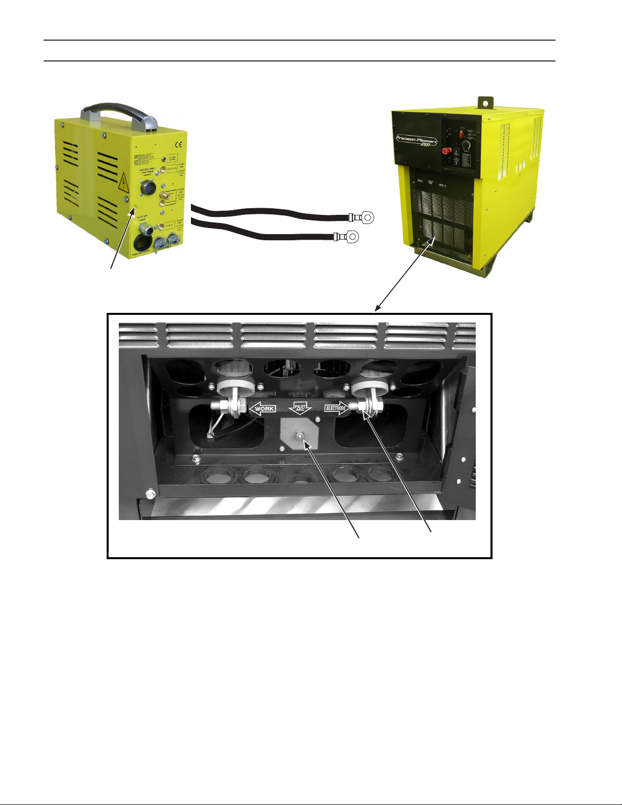
Connections to the Power Supply
1. A power output cable attaches to a large bolted connection labeled “Electrode”.
2. The Pilot Arc cable connects to a small threaded stud labeled “Pilot Arc”.
3. The Plasma Control Interface connects to the power supply. The PCC-14 Plumbing Box control cable connects to the
Plasma Control Interface.
4. A work cable connects to the "Work" terminal on the front-lower-left of the console. The other end is attached to the
cutting table or work piece.
Connections to the rear of the Plumbing Box
1. The Start, Cut & Shield gas hoses from the regulator panel attach to the rear of the plumbing box.
2. The Plumbing Box Control cable from the Plasma Control Interface connects to the amphenol receptacle labeled
“CONTROL CABLE FROM POWER SOURCE”.
Both power cables, the pilot arc cable and both coolant hoses enter the plumbing box from the rear and are connected
internally.
Connections to the Coolant Circulator
1. The coolant supply and return lines connect to the supply and return ttings on the coolant circulator.
3.5 PCC-14 Plumbing Box Mounting Hole Locations
Install the PCC-14 Plumbing Box in an appropriate location so as to maintain adequate and unrestricted airow
into and out of the cabinetry. For permanent mounting refer to the gure below for mounting hole dimensions
in the base of this unit.
16.625"
(422.28 mm)
12.500"
(317.5 mm)
2.125"
(53.98 mm)
(26.92 mm)
4.500"
(114.3 mm)
1.060"
6.875"
(174.63 mm)
29

30

Plasma Control Interface
31

32

SECTION 3 Plasma Control InterfaCe DesCrIPtIon / InstallatIon
PS
CNC PCC-14
E-STOP
1A
3.6 General
This unit is an integral component of the m3 Manual Gas Control Plasma
system used by an external controller (e.g. CNC) to interface with the PCC14 Plumbing Box. It controls all the sequencing required for handling the
plasma cutting/marking operation leaving the external controller with a
simple interface to the Plasma Control Interface (PCI).
3.7 Scope
The purpose of this manual is to provide the operator with all the information required to install and operate the Plumbing Box & Plasma Control
Interface. Technical reference material is also provided to assist in troubleshooting.
Specications: Plasma Control Interface
Weight : 17.0 lbs. (7.7 kg)
13.67”
(347.2 mm)
6.59”
(167.4 mm)
15.50”
(393.7 mm)
33
SECTION 3 Plasma Control InterfaCe DesCrIPtIon / InstallatIon
PS
CNC PCC-14
E-STOP
1A
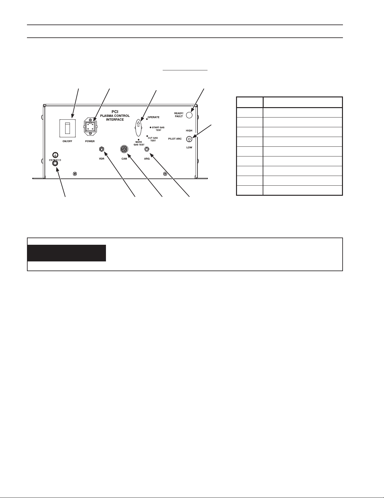
3.8 Plasma Control Interface Connections
FRONT VIEW
A C D
J
Note:
Chassis must be connected to
the machine ground.
WARNING
B
ITEM Description
A ON/OFF SWITCH
E
H
G
F
B POWER INPUT
C MODE SELECT
D READY/FAULT INDICATOR
E PILOT ARC
F ARGON SELECT OUTPUT
G CAN INPUT
H VDR INPUT
J GROUND STUD
ELECTRIC SHOCK CAN KILL!
SHUT OFF POWER AT THE POWER SUPPLY BEFORE ATTEMPTING ANY
MAINTENANCE.
A. On/O Switch – This switch controls the input power on/o to the PCI.
B. Power Input – Connect the 120/230VAC supply to this connector.
C. Mode Select - The PCI can be operated in four dierent modes which can be set using the “MODE SELECT” switch.
1. Operate – Used for normal cutting/marking operation.
2. Start Gas Test – Used for testing and setting the start gas pressure. The pressure value can be monitored on the
“Plasma Gas” gauge display on the PCC-14 Plumbing Box. This also turns on the shield gas output and it’s value
can be monitored on the “Shield Gas” gauge display.
3. Cut Gas Test - Used for testing and setting the cutting gas pressure. The pressure value can be monitored on the
“Plasma Gas” gauge display on the PCC-14 Plumbing Box. This also turns on the shield gas output and it’s value
can be monitored on the “Shield Gas” gauge display.
4. Mark Gas Test (Optional) - Used for testing and setting the argon gas pressure. The pressure value can be monitored on the “Plasma Gas” gauge display on the PCC-14 Plumbing Box. This also turns on the shield gas output
and it’s value can be monitored on the “Shield Gas” gauge display.
D. Ready/Fault Indicator – This LED indicates the dierent fault modes encountered by the PCI. Refer to “Plasma Con-
trol Interface STATUS Codes” section for more details.
E. Pilot Arc - The Pilot Arc High/Low switch on the unit is set based on the type of material being cut. Depending on
the material to be cut, the position of this switch is obtained from the PCC-14 Cut Data manual provided with the
plasma system.
F. Argon Select Output – This connector is used to select the argon solenoid for plasma gas when marking.
G. Can Input – Not used
H. VDR Input – Supplies the arc voltage value divided with a ratio of 25:1 for cutting and 12.5:1 for marking to the PCI.
From the PCI this value is supplied to the external controller for torch height control.
J. Ground Stud – Connect the machine chassis to this stud.
34

SECTION 3 Plasma Control InterfaCe DesCrIPtIon / InstallatIon
REAR VIEW
A
PS
CNC PCC-14
E-STOP
B
C
ITEM Description
A PS
1A
D
F
E
B E-STOP
C FUSE 1A
D AIR CURTAIN/BUBBLE MUFFLER
E PCC-14
F CNC
A. PS – Connects directly to the EPP-201/360 power supply. It carries all the control signals for the power supply.
B. E-STOP – Provides interconnection between the E-STOP actuator on the power supply and the customer’s E-STOP
control circuit. See section 3.9 Typical / Recommended ESTOP Connection for typical wiring schematic.
C. Fuse 1A – This fuse is rated at 1 Amp and is for protecting the internal transformer in the PCI.
D. Air curtain/Bubble Muer (Optional) – Connects with an ESAB supplied Air Curtain or Bubble Muer unit.
E. PCC-14 – Connects with the PCC-14 Plumbing Box.
F. CNC – Connects to the external CNC.
35

1A
SECTION 3 Plasma Control InterfaCe DesCrIPtIon / InstallatIon
PIN Function
A Not Used
B Coolant Flow SW
C Mark Mode
D Chassis
E E-Stop to PS– 24vac
F E-Stop to PS– 24vac
G 24 VDC to PS
H Master Select
J Current Ref Common
K Coolant Level SW
L Current Reference
M Plasma Start
N Pilot Ref Common
P Main Arc On
Q Pilot Arc Select Bit 1
R 120 VAC from PS
S Pilot Arc Select Bit 0
T Current Range Select
V Upslope Select
W Power Supply Fault
Y Main Arc Actual Current
Z 120 VAC Common
PS
CNC PCC-14
E-STOPPS
PIN Function
A E-Stop to CNC
B E-Stop to CNC
E-STOP
PCC-14
PIN Function
A 24 VDC to Pressure SW
B Pressure SW Input
C Not Used
D Not Used
E Start Gas ON
F Solenoid Common
G Cut Gas ON
H Shield Gas ON
J Solenoid 2 Common
M Plasma HF ON
N HF Common
Not Used
Not Used
Not Used
Not Used
Not Used
Not Used
Not Used
Not Used
CNC
PIN Function
A Cycle Start
B Mark Mode
C 24 VDC to CNC
D Fault
E Motion Enable
F CNC Common
G Remote Current Ref
H Remote Current COM
J E-stop to PS
K E-stop to PS
L VDR -
M VDR +
N E-stop to CNC
P E-stop to CNC
R Preow
36

SECTION 3 Plasma Control InterfaCe DesCrIPtIon / InstallatIon
The external controller/CNC connector pin out is described below:
CNC:
A) Cycle Start - Digital input to the PCI which starts the cutting operation when the mode select is in Operate setting.
B) Mark Mode - Digital input to the PCI which enables marking mode on the PCI and the Power Supply.
C) 24VDC to CNC – Supplied to the CNC for Cycle Start and Mark Mode inputs.
D) Fault - Digital output to the CNC reporting a fault with the plasma system.
E) Motion Enable - Digital output to the CNC conrming arc transfer.
F) CNC Common - Voltage supplied from the CNC for fault and motion enable.
G) Remote Current Ref - 0-10 VDC Analog voltage input to PCI which corresponds to 0-360 Amps on the Power Supply.
H) Remote Current Com - DC common for analog voltage.
J) ESTOP to PS - 24 VAC supply to dry contact on emergency stop circuit on CNC. Used to report emergency stop on
external controller or machine to the Power Supply.
K) ESTOP to PS - 24 VAC return on dry contact on emergency stop circuit on CNC. Used to report emergency stop on
external controller to the Power Supply.
L) VDR(-) - Arc voltage feedback to the torch height control circuit on CNC.
M) VDR(+) - Arc voltage common to the torch height control circuit on CNC.
N) ESTOP to CNC - Dry contact from Power Supply. Used to report emergency stop on Power Supply to external con-
troller.
P) ESTOP to CNC - Dry contact from Power Supply. Used to report emergency stop on Power Supply to external con-
troller.
R) Preow - Unit is switched to preow to purge gas lines.
3.9 Typical / Recommended ESTOP Connection
37

SECTION 3 Plasma Control InterfaCe DesCrIPtIon / InstallatIon
3.10 Control Sequence
38

SECTION 3 Plasma Control InterfaCe DesCrIPtIon / InstallatIon
3.11 Plasma Control Interface Mounting Hole Locations
Install the Plasma Control Interface in an appropriate location so as to maintain adequate and unrestricted airow into and
out of the cabinetry. For permanent mounting refer to the gure below for mounting hole dimensions in the base of this unit.
15.50"
(393.7 mm)
14.50"
7.25"
(184.2 mm)
1.75"
(44.5 mm)
6.50"
(165.1 mm)
3.50"
(88.9 mm)
(368.3 mm)
4 X Ø 0.28” (7.1 mm)
39

SECTION 3 Plasma Control InterfaCe DesCrIPtIon / InstallatIon
WHEN SUPPLYING POWER TO THE PLASMA CONTROL INTERFACE
WARNING
3.12 Plasma Control Interface STATUS Codes
STATUS Code Label List:
BOX, FOR SAFE OPERATION, IT IS STRONGLY ADVISED TO TURN OFF
POWER TO THE PLASMA CONTROL INTERFACE BOX WHENEVER AN
EMERGENCY STOP IS ENCOUNTERED ON THE SYSTEM.
Ready/Fault LED
The STATUS code is determined by counting the number of intermittent “ON” ashes of the Ready/Fault LED on the
Plasma Control Interface.
# of LED
ashes
1 Power Supply Fault Fault from power supply, check the power supply front panel for details.
2 Pressure Switch Fault Pressure switch inside PCC-14 is not closed, either due to low gas pres-
3 Coolant Flow Fault No coolant ow. Check CC-11.
4 Coolant Level Fault Need to rell coolant to CC-11.
5 Ignition Fault Arc was not able to transfer.
6 Arc On Lost Fault Arc is lost while cutting.
Fault Description/Solution
sure or a bad pressure switch. There are two pressure switches for start
and cut gas which are in series. Both lines must be at the recommended
PS-1 for the switches to stay closed.
40

SECTION 4 MAINTENANCE
ELECTRIC SHOCK CAN KILL! ENSURE THE LINE WALL DIS
CONNECT SWITCH OR CIRCUIT BREAKER IS OPEN BEFORE AT
WARNING
4.0 Maintenance
4.1 General
Maintenance work must be performed by an experienced person. Do not permit untrained persons to inspect, clean, or
lubricate this equipment.
On a regular basis, check cylinder valves, regulators, hoses, and gas connections for leaks using a soap solution or a leak
test solution.
Keep the equipment dry, free of oil and grease, and protected at all times from damage by hot metal and sparks.
TEMPTING ANY INSPECTION OR WORK ON THE INSIDE OF THE
PLUMBING BOX. ALWAYS WEAR SAFETY GOGGLES WITH SIDE
SHIELDS WHEN BLOWING OUT THE EQUIPMENT WITH LOW
PRESSURE AIR.
4.2 Cleaning
Periodically, remove the covers from the equipment and, wearing proper eye protection, blow accumulated dust and dirt
from the air passages and the interior components using clean low-pressure air. It is imperative that the air passages to the
interior of the unit be kept free of dirt accumulation to ensure adequate circulation of cooling air.
The length of time between cleaning will depend on the location of the unit and the amount of dust in the atmosphere.
After cleaning with low-pressure air, check for and tighten any loose hardware, including all electrical connections. Check
for frayed and/or cracked insulation on all power cables and replace if necessary.
ELECTRIC SHOCK CAN KILL! FAILURE TO REPLACE WORN OR
DAMAGED CABLES MAY RESULT IN A BARE CABLE TOUCHING
A GROUNDED SURFACE. THE RESULTING ELECTRICAL ARC MAY
WARNING
DAMAGE THE UNPROTECTED EYES AND WILL PRESENT A SE
RIOUS FIRE HAZARD. BODILY CONTACT WITH A BARE CABLE,
CONNECTOR, OR CONDUCTOR MAY RESULT IN SEVERE ELEC
TRICAL SHOCK, CAUSING SERIOUS BURNS OR DEATH.
41

SECTION 4 MAINTENANCE
42

SECTION 5 MARKING MODULE
5.0 Marking Module
The Marking Module option is installed external to the PCC-14 Plumbing box and is controlled from the PCI Plasma Control
Interface. This module will route the normal cut gas to the Plumbing Box until the operator selects a Marking operation.
When this happens, the PCI Interface will switch the cut gas sent to the torch to Argon for marking operations. The module
is supplied with 24 VAC from the PCI for operation
Gas connection:
Cut gas and Argon are connected as in the photo below. The gas output is sent to the Plumbing Box.
Electrical connection:
A three pin cable is connected from the Marking Module to the PCI to switch the gas supplied to the torch. By default the
Marking Module will pass the cut gas to the Plumbing Box. This cable is supplied with the module at installation. This cable
routes 24VAC to the Marking Module from the PCI during marking operations.
Cut Gas
Argon
Gas out to PCC-14
PCI connection
43
SECTION 5 MARKING MODULE
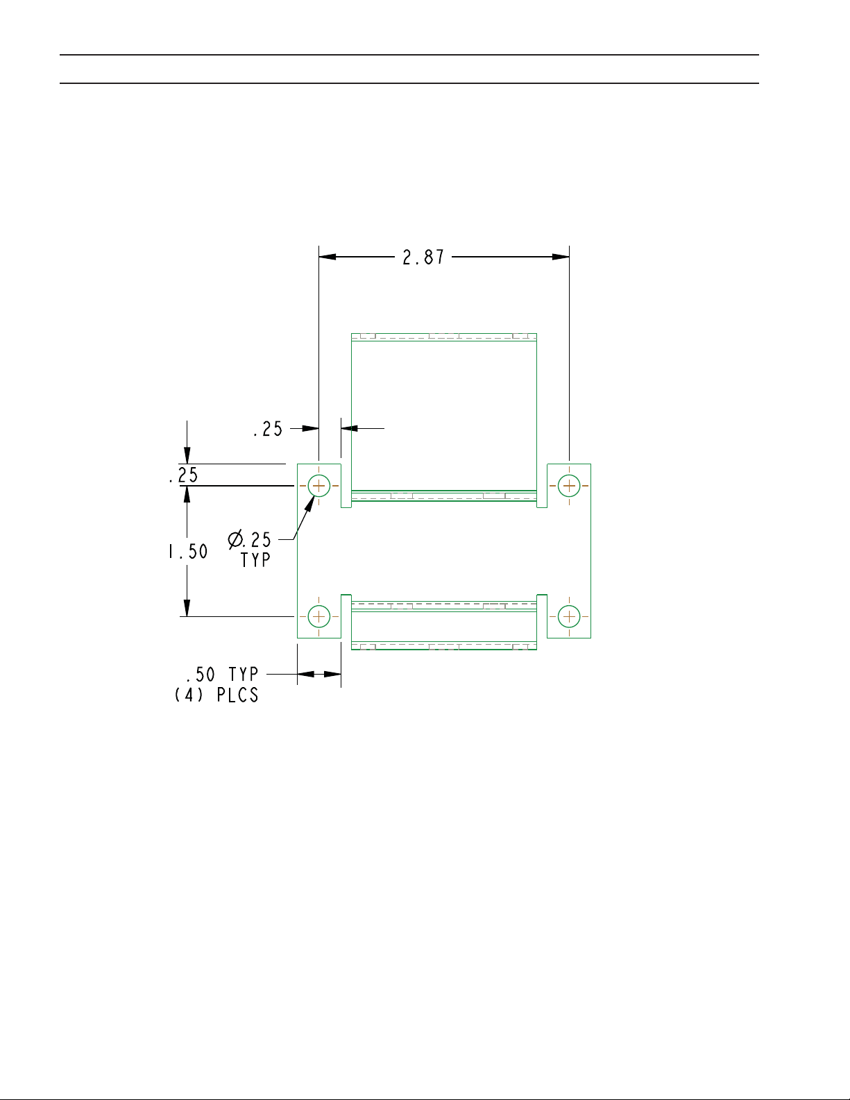
5.1 Marking Module Mounting Hole Locations
Install the Marking Module in an appropriate location so as to maintain adequate and unrestricted airow into and out of
the cabinetry. For permanent mounting refer to the gure below for mounting hole dimensions in the base of this unit.
2.87
.25
.25
1.50
.50
(4) PLCS
.25
TYP
TYP
44
SECTION 6 PT36R PLASMA TORCH
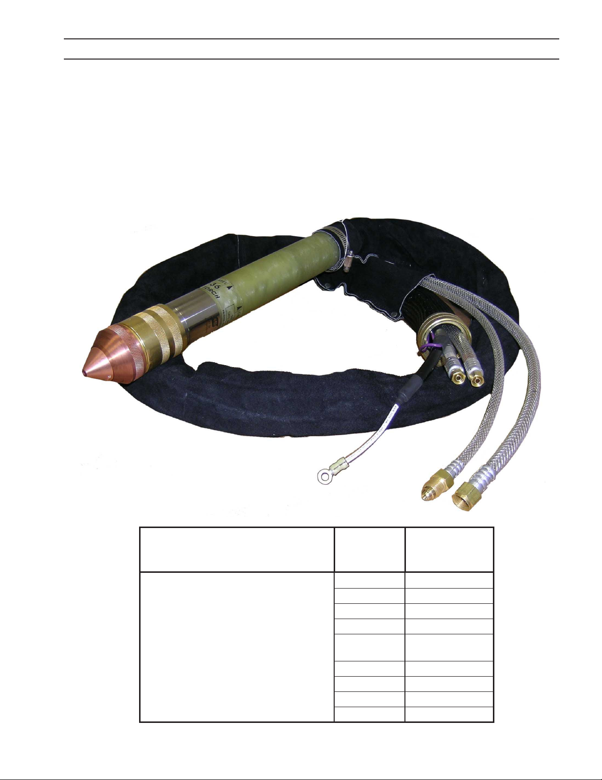
6.0 PT-36R Plasma Torch
Note:
See appropriate PT-36R Plasma Torch equipment literature (0558006829) for operating conditions and instruc-
tion information.
Torch
Description
PT-36R m3
Plasma Torch
45
Available
Lengths
m ( ft. )
1.4m (4.5’) 0558006811
1.8m (6’) 0558006812
2.2m (7.2’) 0558006781
3.6m (12’) 0558006813
4.3m (14’)
mini-bevel
4.6m (15’) 0558006815
5.2m (17’) 0558006816
6.1m (20’) 0558006782
7.6m (25’) 0558006817
ESAB
Part Number
0558006814
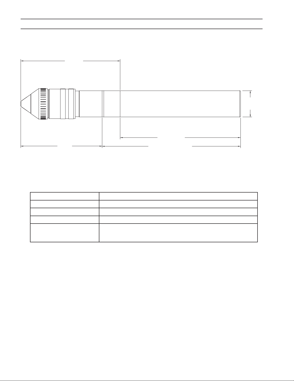
SECTION 6 PT36R PLASMA TORCH
6.1 PT-36R Technical Specications
7.54"
(191.5mm)
6.17"
(156.7mm)
Clamp only on insulated torch sleeve not less than
1.25" (31.7mm) from the torch end of sleeve.
(231.9mm)
10.50" (266.7mm)
Length of Sleeve
NOTE:
2.00"
(50.8mm)
9.13"
6.2 Gas Specications
Argon 125 PSI (8,6 bar) with 0.25” NPT, 99.995% purity, Filtered to 25 microns
Nitrogen 125 PSI (8,6 bar) with 0.25” NPT, 99.99% purity, Filtered to 25 microns
Oxygen 125 PSI (8,6 bar) with 0.25” NPT, 99.5% purity, Filtered to 25 microns
Ar/H2 (Argon/Hydrogen) 75 PSI (5,2 bar), Speciality Gas, 99.995% purity, Filtered to 25 microns
Compressed Air
(Clean, dry & oil-free shop
air)
Typical requirements for ow delivered at 125 psig: Maximum Plasma Gas: 300 scfh Maximum Shield Gas: 350 scfh
80 PSI @ 1200cfh (5,5 bar @ 35 m
3
h), Filtered to 25 microns
Note:
These do not represent actual ows used in any condition, but are the design maximums of the system.
46

SECTION 6 PT36R PLASMA TORCH
6.3 Recommended Regulators
Liquid Cylinder Service:
O2 : R-76-150-540LC ................................................................................................................P/N 19777
N2 : R-76-150-580LC ................................................................................................................P/N 19977
High Pressure Cylinder Service:
O2 : R-77-150-540 .................................................................................................................. P/N 998337
Ar & N2 : R-77-150-580 .......................................................................................................... P/N 998344
H2 & CH4 : R-77-150-350 ..................................................................................................... P/N 998342
Industrial Air : R-77-150-590 ............................................................................................ P/N 998348
Station/Pipeline Service:
O2 : R-76-150-024 .....................................................................................................................P/N 19151
Ar & N2 : R-76-150-034 .............................................................................................................P/N 19155
Air, H2, & CH4 : R-6703 .............................................................................................................P/N 22236
6.4 PT-36R Torch Technical Specications
Type: Water cooled, Dual gas, mechanized plasmarc cutting torch
Current Rating: 750 Amps @ 100% duty cycle
Mounting Diameter: 2 inches (50.8 mm)
Length of Torch without leads: 18.5 inches (47 cm)
IEC 60974-7 Voltage Rating: 500 volts peak
Striking Voltage (maximum value of HI-FREQUENCY voltage): 8000 vac
Minimum Coolant Flowrate: 1.0 USGPM (3.8 L/min)
Minimum Operating Coolant Pressure at Inlet: 175 psig (12.1 bars)
Maximum Operating Coolant Pressure at Inlet: 200 psig (13.8 bars)
Minimum Acceptable Rating of Coolant Recirculator:
16,830 BTU/HR (4.9 kW) at High Coolant Temperature - Ambient = 45°F (25°C) and 1.6 USGPM (6 L/min)
Maximum Safe Gas Pressures at Inlets to Torch: 125 psig (8.6 bars)
Recommended Input Pressure: 125 psig (8.6 bars)
Safety Interlocks: This torch is intended for use with ESAB Plasmarc cutting systems and controls employing a water ow
switch on the coolant return line from the torch. Removal of the nozzle retaining cup to service the torch breaks the
coolant return path.
47

SECTION 6 PT36R PLASMA TORCH
48

SECTION 7 COOLANT CIRCULATOR
7.0 Coolant Circulator
Note:
See appropriate Coolant Circulator equipment literature (0558007523) for operating conditions and instruction
information.
49

SECTION 7 COOLANT CIRCULATOR
7.1 Specications
Dimensions: 34.00” high (864 mm) x 21.75” wide (552 mm) x 28.00 deep (711 mm)
Weight: 215 lb. dry (97.5 kg) / 249 lb. wet (113 kg)
Pump Type: Positive displacement, rotary vane type with adjustable by-pass valve (200 psi / 13.8 bars max.),
CW rotation as viewed from nameplate.
Radiator Type: Copper tubing, aluminum nned air-to-water type with galvanized steel frame.
AC Input Voltages
AC Input Amperage 9 / 8 / 5 / 4 / 3 Amperes
Pump Capacity
Cooling Capacity @ 1.60 gpm (6.0 l/min) 16,830 BTU / hr. (4900 watts) 20,200 BTU / hr. (5900 watts)
at 45° F (25° C) temperature dierence between high coolant temperature and ambient air temperature using ESAB cool-
ant P/N 0558004297 (25% propylene glycol / 75% distilled water).
Max. Delivery Pressure 175 psig (12 bars)
Reservoir Capacity 4 gallons (15.2 liters)
50Hz, 1 Phase Input Power 60Hz, 1 Phase Input Power
200 / 230 / 400 / 460 / 575 V., + / - 10%
1.60 gpm at 175 psi
(6.0 l/min at 12 bars)
1.60 gpm at 175 psi
(6.0 l/min at 12 bars)
50

SECTION 7 COOLANT CIRCULATOR
7.2 Installation
Install the CC-11 in an appropriate location so as to maintain adequate and unrestricted airow into and out of the cabinetry. For permanent mounting refer to Figure 6.1 for mounting hole dimensions in the base of this unit.
0.531” (13.5 mm) diameter hole, typical, 8 places
19.50”
(495 mm)
1.69”
(43 mm)
3.42”
(87 mm)
17.78”
(452 mm)
Figure 6.1 Mounting Dimensions
3.42”
(87 mm)
51

SECTION 7 COOLANT CIRCULATOR
7.3 Input Power Connections
A 3-conductor power cable suitable to meet the required input power must be installed. The cable must have 0.25" (6.4
mm) ring lugs installed on the machine end. Connect the power leads to the L1 and L2 terminals on TB1 Input Power Terminal Board and the ground lead to the ground lug on the back of the fan support panel. A strain relief tting is provided
to feed a power cable through the rear panel of the cabinet. Refer to Figure 6.2 for proper Input Voltage Link placement,
Figure 6.2 shows link in place for 460 volt input. Electrical installation must be in accordance with local electrical codes for
this type of equipment.
Voltage link MUST be moved if equipment is operated at any volt-
CAUTION
age other than 575V. Failure to move voltage link to location that
matches input voltage can result in damage to equipment.
NOTE:
Voltage link is shipped in
this location which is for
575 volt operation.
Figure 6.2 Voltage Links
52

SECTION 7 COOLANT CIRCULATOR
WARNING
ELECTRIC SHOCK CAN KILL! BEFORE MAKING ELECTRICAL INPUT
CONNECTIONS TO THE POWER SOURCE, "MACHINERY LOCKOUT
PROCEDURES" SHOULD BE EMPLOYED. IF THE CONNECTIONS ARE
TO BE MADE FROM A LINE DISCONNECT SWITCH, PLACE THE SWITCH
IN THE OFF POSITION AND PADLOCK IT TO PREVENT INADVERTENT
TRIPPING. IF THE CONNECTION IS MADE FROM A FUSE BOX, REMOVE
THE CORRESPONDING FUSES AND PADLOCK THE BOX COVER. IF IT IS
NOT POSSIBLE TO USE PADLOCKS, ATTACH A RED TAG TO THE LINE
DISCONNECT SWITCH OR FUSE BOX WARNING OTHERS THAT THE
CIRCUIT IS BEING WORKED ON.
Typical Installation -
User-supplied single phase fused power disconnect box with
receptacle and plug
Input Power Cable
Figure 6.3 Input Connection Diagram
53

SECTION 7 COOLANT CIRCULATOR
54
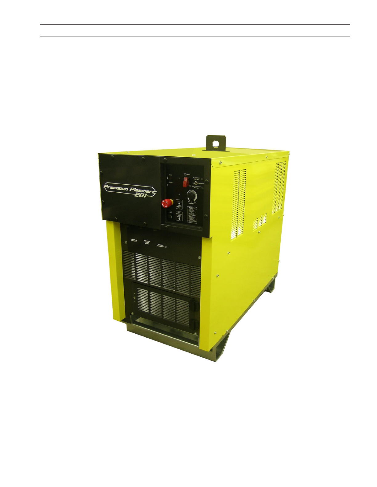
SECTION 8 POWER SUPPLIES
8.0 EPP-201 Power Supply
Note:
See appropriate EPP-201 Power Supply equipment literature (0558007900) for operating conditions and instruc-
tion information.
55

SECTION 8 POWER SUPPLIES
8.1 Dimensions and Weight
40.75”
(1035 mm)
23.75”
(603.25 mm)
47.25”
(1200 mm)
Weight = 492 kg (1085 lbs.)
56

SECTION 8 POWER SUPPLIES
8.2 Input Power Connection
ELECTRIC SHOCK CAN KILL!
PROVIDE MAXIMUM PROTECTION AGAINST ELECTRICAL SHOCK.
WARNING
Primary Power
EPP-201 is a 3-phase unit. Input power must be provided from a line (wall) disconnect switch that contains fuses or circuit
breakers in accordance to local or state regulations.
BEFORE ANY CONNECTIONS ARE MADE INSIDE THE MACHINE, OPEN
THE LINE WALL DISCONNECT SWITCH TO TURN POWER OFF.
Recommended input conductor and line fuse sizes:
Input at Rated Load Input and Ground
Volts Amperes
380 60 35 (2/0)* 100
400 57 35 (2/0)* 100
460 51 35 (2/0)* 100
575 41 35 (2/0)* 60
Rated load is output of 200A at 160V
* Sizes per National Electrical Code for a 90° C (194˚ F) rated copper conductors @ 40° C (104˚ F) ambient. Not more than
three conductors in raceway or cable. Local codes should be followed if they specify sizes other than those listed above.
To estimate the input current for a wide range of output conditions, use the formula below.
Input current =
NOTICE
Dedicated power line may be necessary.
EPP-201 is equipped with line voltage compensation but to avoid
impaired performance due to an overloaded circuit, a dedicated
power line may be required.
(V arc) x (I arc) x 0.73
(V line)
conductor* CU/
mm2 (AWG)
Time delay
Fuse size
(amperes)
57

SECTION 8 POWER SUPPLIES
58

SECTION 9 POWER SUPPLIES
9.0 EPP-360 Power Supply
Note:
See appropriate EPP-360 Power Supply equipment literature (0558007676) for operating conditions and instruc-
tion information.
59
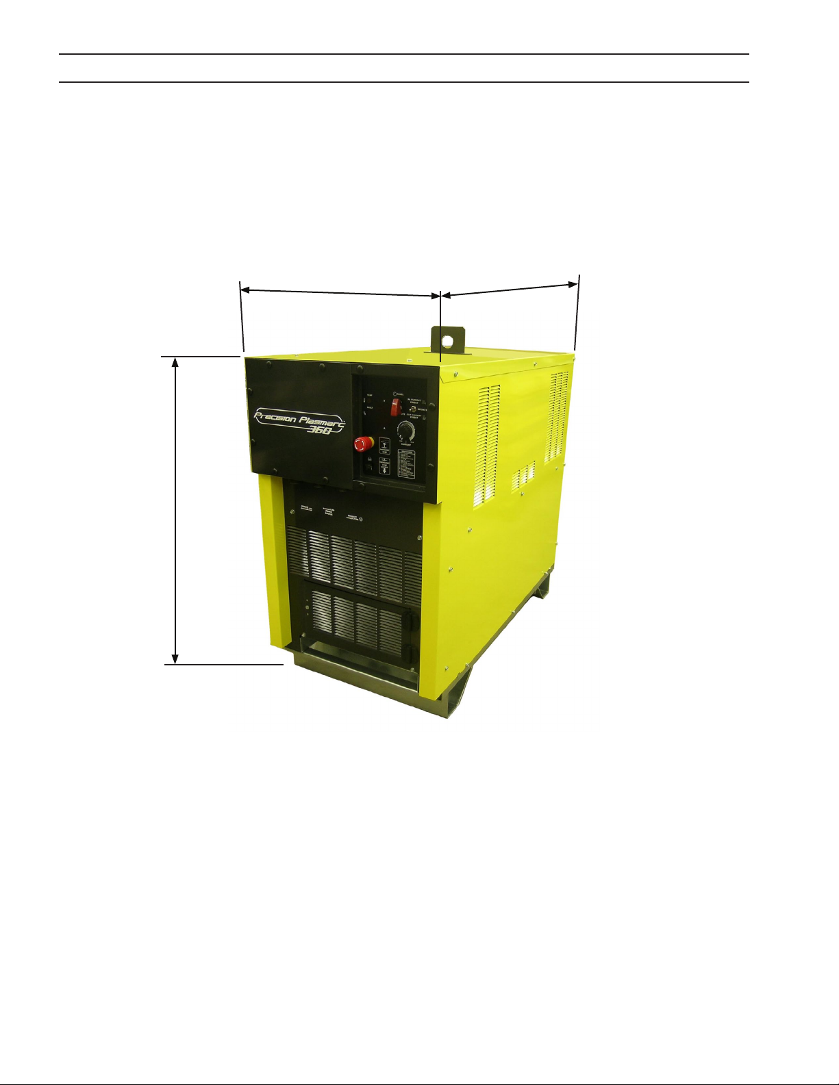
SECTION 9 POWER SUPPLIES
9.1 Dimensions and Weight
40.75”
(1035 mm)
23.75”
(603.25 mm)
47.25”
(1200 mm)
Weight = 492 kg (1085 lbs.)
60

SECTION 9 POWER SUPPLIES
9.2 Input Power Connection
ELECTRIC SHOCK CAN KILL!
PROVIDE MAXIMUM PROTECTION AGAINST ELECTRICAL SHOCK.
WARNING
Primary Power
EPP-360 is a 3-phase unit. Input power must be provided from a line (wall) disconnect switch that contains fuses or circuit
breakers in accordance to local or state regulations.
BEFORE ANY CONNECTIONS ARE MADE INSIDE THE MACHINE, OPEN
THE LINE WALL DISCONNECT SWITCH TO TURN POWER OFF.
Recommended input conductor and line fuse sizes:
Input at Rated Load Input and Ground
Volts Amperes
380 140 95 (4/0)* 200
400 132 95 (4/0)* 200
460 115 35 (2)* 150
575 92 35 (2)* 125
Rated load is output of 360A at 200V
* Sizes per National Electrical Code for a 90° C (194˚ F) rated copper conductors @ 40° C (104˚ F) ambient. Not more than
three conductors in raceway or cable. Local codes should be followed if they specify sizes other than those listed above.
To estimate the input current for a wide range of output conditions, use the formula below.
Input current =
NOTICE
Dedicated power line may be necessary.
EPP-360 is equipped with line voltage compensation but to avoid
impaired performance due to an overloaded circuit, a dedicated
power line may be required.
(V arc) x (I arc) x 0.73
(V line)
conductor* CU/
mm2 (AWG)
Time delay
Fuse size
(amperes)
61

SECTION 9 POWER SUPPLIES
62

SECTION 10 HOSES AND CABLES
10.0 HOSES AND CABLES
10.1 Hoses
Hose
Description
Air / Shield Gas Hose
Available
Lengths
m ( ft. )
1.5m (5’) 0558006200
5m (16’) 0558006201
6m (19’) 0558006202
7m (23’) 0558006203
8m (26’) 0558006204
9m (30’) 0558006205
10m (33’) 0558006206
11m (36’) 0558006207
12m (39’) 0558006208
13m (43’) 0558006209
14m (46’) 0558006210
15m (49’) 0558006211
16m (52’) 0558006212
17m (56’) 0558006213
18m (59’) 0558006214
19m (62’) 0558006215
20m (66’) 0558006216
30m (98') 0558008813
2.3m (7.5’) 0558007315
4m (13’) 0558008359
0.5m (1.7’) 0558008447
1m (3.3’) 0558008448
3m (10’) 0558008449
ESAB
Part Number
63

SECTION 10 HOSES AND CABLES
Hose
Description
N2 / PG-1 Hose
Available
Lengths
m ( ft. )
1.5m (5’) 0558006089
5m (16’) 0558006090
6m (19’) 0558006091
7m (23’) 0558006092
8m (26’) 0558006093
9m (30’) 0558006094
10m (33’) 0558006095
11m (36’) 0558006096
12m (39’) 0558006097
13m (43’) 0558006098
14m (46’) 0558006099
15m (49’) 0558006100
16m (52’) 0558006101
17m (56’) 0558006102
18m (59’) 0558006103
19m (62’) 0558006104
20m (66’) 0558006105
30m (98') 0558008814
2.3m (7.5’) 0558007313
4m (13’) 0558008357
0.5m (1.7’) 0558008441
1m (3.3’) 0558008442
3m (10’) 0558008443
ESAB
Part Number
64

SECTION 10 HOSES AND CABLES
Hose
Description
O2 / PG-2 Hose
Available
Lengths
m ( ft. )
1.5m (5’) 0558006106
5m (16’) 0558006107
6m (19’) 0558006108
7m (23’) 0558006109
8m (26’) 0558006110
9m (30’) 0558006111
10m (33’) 0558006112
11m (36’) 0558006113
12m (39’) 0558006114
13m (43’) 0558006115
14m (46’) 0558006116
15m (49’) 0558006117
16m (52’) 0558006118
17m (56’) 0558006119
18m (59’) 0558006120
19m (62’) 0558006121
20m (66’) 0558006122
30m (98') 0558008815
2.3m (7.5’) 0558007314
4m (13’) 0558008358
0.5m (1.7’) 0558008444
1m (3.3’) 0558008445
3m (10’) 0558008446
ESAB
Part Number
65

SECTION 10 HOSES AND CABLES
Hose
Description
H35 / CH4 Hose
Argon Hose
Available
Lengths
m ( ft. )
0.5m (1.7’) 0558008371
1m (3.3’) 0558008372
2.3m (7.5’) 0558008373
3m (10’) 0558008374
4m (13’) 0558008375
5m (16’) 0558008376
6m (19’) 0558008377
7m (23’) 0558008378
8m (26’) 0558008379
9m (30’) 0558008380
10m (33’) 0558008381
11m (36’) 0558008382
12m (39’) 0558008383
13m (43’) 0558008384
14m (46’) 0558008385
15m (49’) 0558008386
16m (52’) 0558008387
17m (56’) 0558008388
5m (16’) 0558008390
6m (19’) 0558008391
7m (23’) 0558008392
8m (26’) 0558008393
9m (30’) 0558008394
10m (33’) 0558008395
11m (36’) 0558008396
12m (39’) 0558008397
13m (43’) 0558008398
14m (46’) 0558008399
15m (49’) 0558008400
16m (52’) 0558008401
17m (56’) 0558008402
40m (132’) 0558008816
ESAB
Part Number
66

SECTION 10 HOSES AND CABLES
Hose
Description
Coolant Hose
Air Curtain Hose
Available
Lengths
m ( ft. )
10.1m (33’) 0558005563
15.2m (50’) 0558005564
20.1m (66’) 0558005565
35.1m (115’) 0558005566
50.3m (165’) 0558005567
4.9m (16’) 0558005246
29.9m (98’) 0558005247
39.9m (131’) 0558005248
59.7m (196’) 0558005249
1.4m (4.5’) 0558004841
1.8m (6’) 0558004842
3.6m (12’) 0558004843
4.6m (15’) 0558004844
5.2m (17’) 0558004845
7.6m (25’) 0558004846
6m (20’) 0558006865
7m (23’) 0558008502
8m (26’) 0558008503
9m (30’) 0558008504
10m (33’) 0558008505
11m (36’) 0558008506
12m (40’) 0558008507
ESAB
Part Number
67

SECTION 10 HOSES AND CABLES
10.2 Cables
Cable
Description
E-Stop Cable
( E-Stop )
Air Curtain / Bubble Muer
Control Cable ( optional )
VDR Cable ( VDR )
Mark Solenoid Cable ( ARG )
Available
Lengths
m ( ft. )
7.6m (25’) 0558009621
10m (33’) 0558009622
15m (50’) 0558009623
22m (75’) 0558009624
30m (100’) 0558009625
40m (131’) 0558009626
45m (150’) 0558009627
50m (164’) 0558009628
60m (200’) 0558009629
2.1m (6.75’) 0558009771
5m (16.5’) 0558009772
10m (33') 0558009773
0.5m (1.7’) 0560947067
1.5m (5’) 0560947075
3m (10’) 0560947076
4m (13’) 0560947068
5m (16’) 0560947077
6m (19’) 0560947069
6.1m (20') 0560946782
7m (23’) 0560947070
8m (26’) 0560947071
9m (30’) 0560947072
10m (33’) 0560947078
15m (49’) 0560947073
20m (66’) 0560947074
25m (82') 0560946758
ESAB
Part Number
68

SECTION 10 HOSES AND CABLES
Cable
Description
PCC-14 Interface Cable
( PCC-14 )
115 / 230 VAC Input Power Cable
( POWER )
CNC Cable
( CNC )
EPP Control Cable
( PS-1 )
Available
Lengths
m ( ft. )
0.9m (3’) 2238279
1.8m (6’) 2237958
3.0m (10’) 0558009510
4.0m (13’) 0558009511
4.9m (16’) 0558009512
6.1m (20’) 0558009513
7.0m (23’) 0558009514
7.9m (26’) 0558009515
9.1m (30’) 0558009516
10.1m (33’) 0558009517
15.2m (50’) 2237959
22.9m (75’) 2237960
30.5m (100’) 2237934
38.1m (125’) 2237935
45.7m (150’) 2237936
53.3m (175’) 2237937
61.0m (200’) 2237938
5m (16’) 0558008261
10m (33’) 0558008262
15m (49') 0558008810
20m (66’) 0558008811
25m (82') 0558008812
4.6m (15’) 0560936665
7.6m (25’) 0560936666
15m (50’) 0560936667
22.8m (75’) 0560936668
25m (82’) 0560948159
7.6m (25’) 0558004651
10m (33’) 0558008360
15m (50’) 0558004652
22.8m (75’) 0558004653
30.5m (100’) 0558004654
40m (131’) 0558003978
45.7m (150’) 0558004655
50m (164’) 0558008355
60m (200’) 0558008356
ESAB
Part Number
69

SECTION 10 HOSES AND CABLES
70

SECTION 11 REPLACEMENT PARTS
11.0 Replacement Parts
11.1 General
Always provide the serial number of the unit on which the parts will be used. The serial number is stamped on
the unit nameplate.
11.2 Ordering
To ensure proper operation, it is recommended that only genuine ESAB parts and products be used with this
equipment. The use of non-ESAB parts may void your warranty.
Replacement parts may be ordered from your ESAB Distributor.
Be sure to indicate any special shipping instructions when ordering replacement parts.
Refer to the Communications Guide located on the back page of this manual for a list of customer service phone
numbers.
Note
Bill of material items that have blank part numbers are provided for customer information only.
Hardware items should be available through local sources.
Note
Replacement Parts, Schematics and Wiring Diagrams are
printed on 279.4mm x 431.8mm (11” x 17”) paper and are
included inside the back cover of this manual.
71

NOTES
72

REVISION HISTORY
1. Original release - 03/2010
2. Revision 07/2010 - corrected serial #’s on front cover.
3. Revision 05/2011 - minor changes to chart on page 35 and 68.
73

ESAB Welding & Cutting Products, Florence, SC
COMMUNICATION GUIDE - CUSTOMER SERVICES
A. CUSTOMER SERVICE QUESTIONS:
Telephone: (800)362-7080 / Fax: (800) 634-7548 Hours: 8:00 AM to 7:00 PM EST
Order Entry Product Availability Pricing Order Information Returns
B. ENGINEERING SERVICE:
Telephone: (843) 664-4416 / Fax : (800) 446-5693 Hours: 7:30 AM to 5:00 PM EST
Warranty Returns Authorized Repair Stations Welding Equipment Troubleshooting
C. TECHNICAL SERVICE:
Telephone: (800) ESAB-123/ Fax: (843) 664-4452 Hours: 8:00 AM to 5:00 PM EST
Part Numbers Technical Applications Specications Equipment Recommendations
D. LITERATURE REQUESTS:
Telephone: (843) 664-5562 / Fax: (843) 664-5548 Hours: 7:30 AM to 4:00 PM EST
E. WELDING EQUIPMENT REPAIRS:
Telephone: (843) 664-4487 / Fax: (843) 664-5557 Hours: 7:30 AM to 3:30 PM EST
Repair Estimates Repair Status
F. WELDING EQUIPMENT TRAINING
Telephone: (843)664-4428 / Fax: (843) 679-5864 Hours: 7:30 AM to 4:00 PM EST
Training School Information and Registrations
G. WELDING PROCESS ASSISTANCE:
Telephone: (800) ESAB-123 Hours: 7:30 AM to 4:00 PM EST
H. TECHNICAL ASST. CONSUMABLES:
Telephone : (800) 933-7070 Hours: 7:30 AM to 5:00 PM EST
IF YOU DO NOT KNOW WHOM TO CALL
Telephone: (800) ESAB-123
Fax: (843) 664-4462
Hours: 7:30 AM to 5:00 PM EST
or
visit us on the web at http://www.esabna.com
The ESAB web site oers
Comprehensive Product Information
Material Safety Data Sheets
Warranty Registration
Instruction Literature Download Library
Distributor Locator
Global Company Information
Press Releases
Customer Feedback & Support
 Loading...