

m3 G2 (ICH) Plasma System
Instruction Manual
(use with EPP-201/360/450/601 Power Sources)
0558011509 07/2014

m3 G2 (ICH) Plasma System
2

m3 G2 (ICH) Plasma System
Be sure this information reaches the operator.
You can get extra copies through your supplier.
CAUTION
These INSTRUCTIONS are for experienced operators. If you are not fully familiar with the
principles of operation and safe practices for arc welding and cutting equipment, we urge
you to read our booklet, “Precautions and Safe Practices for Arc Welding, Cutting, and
Gouging,” Form 52-529. Do NOT permit untrained persons to install, operate, or maintain
this equipment. Do NOT attempt to install or operate this equipment until you have read
and fully understand these instructions. If you do not fully understand these instructions,
contact your supplier for further information. Be sure to read the Safety Precautions before installing or operating this equipment.
USER RESPONSIBILITY
This equipment will perform in conformity with the description thereof contained in this manual and accompanying labels and/or inserts when installed, operated, maintained and repaired in accordance with the instructions provided. This equipment must be checked periodically. Malfunctioning or poorly maintained equipment
should not be used. Parts that are broken, missing, worn, distorted or contaminated should be replaced immediately. Should such repair or replacement become necessary, the manufacturer recommends that a telephone
or written request for service advice be made to the Authorized Distributor from whom it was purchased.
This equipment or any of its parts should not be altered without the prior written approval of the manufacturer.
The user of this equipment shall have the sole responsibility for any malfunction which results from improper
use, faulty maintenance, damage, improper repair or alteration by anyone other than the manufacturer or a service facility designated by the manufacturer.
READ AND UNDERSTAND THE INSTRUCTION MANUAL BEFORE INSTALLING OR OPERATING.
PROTECT YOURSELF AND OTHERS!
3

m3 G2 (ICH) Plasma System
4

m3 G2 (ICH) Plasma System
Table of Contents
SAFETY
1.0 Safety - English ...........................................................................................................................................13
Safety - Spanish .................................................................................................................................................................................. 17
Safety - French ....................................................................................................................................................................................21
DESCRIPTION
2.0 System Diagrams ........................................................................................................................................27
Base System ......................................................................................................................................................................................... 28
Base System + AHC ...........................................................................................................................................................................29
Base System + A/C ............................................................................................................................................................................ 30
Base System + WIC ............................................................................................................................................................................ 31
Base System + AHC + WIC .............................................................................................................................................................. 32
Base System + AHC + A/C .............................................................................................................................................................. 33
Base System + WIC + A/C ............................................................................................................................................................... 34
Base System + AHC + WIC + A/C ................................................................................................................................................. 35
2.1 Power Supply ..............................................................................................................................................36
380/400V Power Supplies ............................................................................................................................................................... 36
460/575V Power Supplies ............................................................................................................................................................... 37
2.2 Coolant Circulator (CC-11) ..........................................................................................................................38
Specications ...................................................................................................................................................................................... 38
2.3 Interface Control Hub (ICH) .......................................................................................................................39
Specications ...................................................................................................................................................................................... 39
ICH Mounting Dimensions .............................................................................................................................................................39
CNC Direct Board ..............................................................................................................................................................................40
2.4 Plasma Gas Control (PGC) ..........................................................................................................................41
Functions and Features ................................................................................................................................................................... 43
5

m3 G2 (ICH) Plasma System
Plasma Gas Control Mounting Hole Locations (Bottom View) ..........................................................................................44
Plasma Gas Control Mounting Plate Hole Locations.............................................................................................................44
Plumbing Schematic ........................................................................................................................................................................ 45
Electrical Schematic .........................................................................................................................................................................46
Connections ........................................................................................................................................................................................ 47
Troubleshooting ................................................................................................................................................................................ 47
2.5 Shield Gas Control (SGC) ........................................................................................................................... 48
Functions and Features ................................................................................................................................................................... 51
Shield Gas Control Mounting Hole Locations (Bottom View) ............................................................................................52
Shield Gas Control Mounting Plate Hole Locations .............................................................................................................. 52
Plumbing Schematic ........................................................................................................................................................................ 53
Electrical Schematic .........................................................................................................................................................................54
Connections ........................................................................................................................................................................................ 55
Troubleshooting ................................................................................................................................................................................ 56
Replacement Parts ............................................................................................................................................................................ 56
2.6 Remote Arc Starter (RAS) ...........................................................................................................................58
Specications ...................................................................................................................................................................................... 58
Remote Arc Starter Connections .................................................................................................................................................58
RAS Box Mounting Dimensions ...................................................................................................................................................59
RAS Box Mounting Plate Dimensions ........................................................................................................................................ 59
2.7 PT-36 Plasma Torch ................................................................................................................................... 60
Specications ...................................................................................................................................................................................... 60
2.8 Air Curtain (A/C) ..........................................................................................................................................61
2.9 Water Injection Control (WIC) ...................................................................................................................62
Specications ...................................................................................................................................................................................... 62
2.10 Automatic Height Control (AHC) .............................................................................................................63
Specications ...................................................................................................................................................................................... 63
B4 Mounting Dimensions ...............................................................................................................................................................64
6

m3 G2 (ICH) Plasma System
INSTALLATION
3.0 Grounding ...................................................................................................................................................69
Introduction ........................................................................................................................................................................................ 69
Grounding Overview ....................................................................................................................................................................... 70
Basic Layout ........................................................................................................................................................................................ 71
Elements of a Ground System .......................................................................................................................................................72
Plasma Current Return Path ..........................................................................................................................................................72
Plasma System Safety Ground ...................................................................................................................................................... 73
Rail System Safety Ground ............................................................................................................................................................. 76
Earth Ground Rod ............................................................................................................................................................................. 77
Ground Rod ......................................................................................................................................................................................... 77
Soil Resistivity ..................................................................................................................................................................................... 77
Utility Power Electrical Ground ....................................................................................................................................................78
Multiple Ground Rods .....................................................................................................................................................................79
Machine Grounding Schematic....................................................................................................................................................80
3.1 Placement of Power Supply .......................................................................................................................81
Input Power Connection ................................................................................................................................................................ 81
Input Conductors .............................................................................................................................................................................. 81
Input Connection Procedure ........................................................................................................................................................82
Output Connection Procedure .....................................................................................................................................................82
Interface Cables/Connections.......................................................................................................................................................83
3.2 Placement of CC-11 Coolant Circulator .................................................................................................... 84
Input Power Connection ................................................................................................................................................................84
Coolant Connections and Optional Equipment ..................................................................................................................... 85
3.3 Placement of RAS Box ............................................................................................................................... 86
Connections on the RAS Box ........................................................................................................................................................86
7

m3 G2 (ICH) Plasma System
3.4 Torch Connections ..................................................................................................................................... 88
3.5 Mounting Torch to Machine .....................................................................................................................89
3.6 Placement of ICH ....................................................................................................................................... 90
3.7 Placement of SGC ...................................................................................................................................... 90
3.8 Placement of PGC ...................................................................................................................................... 90
Individual Component Connections .......................................................................................................................................... 91
Component Placement Example ................................................................................................................................................. 92
OPERATION
4.0 Interface Control Hub ................................................................................................................................97
4.1 Operation ................................................................................................................................................... 99
ICH Connectors .................................................................................................................................................................................. 99
Display Screens ................................................................................................................................................................................100
Editing a Parameter on the Display ..........................................................................................................................................100
Setup Descriptions..........................................................................................................................................................................105
Communication Options .............................................................................................................................................................. 106
Station Options ................................................................................................................................................................................ 107
Digital I/O ...........................................................................................................................................................................................109
Digital Inputs ....................................................................................................................................................................................109
Digital Outputs.................................................................................................................................................................................109
4.2 Modes of Operation: ................................................................................................................................ 110
Remote Interface without Serial Communication ............................................................................................................... 110
Operation sequence with ESAB supplied plasma lifter: .................................................................................................... 112
Operation sequence with customer supplied plasma lifter: ............................................................................................ 116
Remote Interface with Serial Communication ...................................................................................................................... 119
Local Interface - Diagnostics Only ............................................................................................................................................. 119
Operation sequence: ......................................................................................................................................................................120
Interface Wiring Descriptions .....................................................................................................................................................122
Interface Wiring ...............................................................................................................................................................................122
8

m3 G2 (ICH) Plasma System
4.3 Maintenance/Troubleshooting ...............................................................................................................126
Communication Problems ........................................................................................................................................................... 126
Digital Input Problems ..................................................................................................................................................................126
Digital Output Problems ............................................................................................................................................................... 126
Gas Problems ....................................................................................................................................................................................126
Power Supply Problems ................................................................................................................................................................ 126
Error Messages on the ICH Display ...........................................................................................................................................127
Module Errors ...................................................................................................................................................................................128
Module Errors ...................................................................................................................................................................................129
Process Errors ....................................................................................................................................................................................130
Process Errors .................................................................................................................................................................................... 131
Process Errors .................................................................................................................................................................................... 132
Process Errors .................................................................................................................................................................................... 133
APPENDIX
ESAB Serial Communication Interface ..........................................................................................................139
Introduction ...................................................................................................................................................................................... 139
System Requirements ....................................................................................................................................................................139
Installation .........................................................................................................................................................................................140
Operation ........................................................................................................................................................................................... 143
ICH Serial Communication Protocol ..............................................................................................................154
Commands ........................................................................................................................................................................................154
ICH Communication Errors ..........................................................................................................................................................161
ICH Login Sequence ....................................................................................................................................................................... 161
ICH Communication Error Messages ........................................................................................................................................162
ICH Parameter Loading ................................................................................................................................................................. 165
9

m3 G2 (ICH) Plasma System
PT-36 Mechanized Plasmarc Cutting Torch ..................................................................................................166
Package Options Available .........................................................................................................................................................166
Optional Accessories ......................................................................................................................................................................166
PT-36 Torch Consumable Kits ......................................................................................................................................................167
Recommended Regulators .......................................................................................................................................................... 170
Connection of Torch to Plasma System ................................................................................................................................... 171
Connection to the Remote Arc Starter Box ............................................................................................................................ 171
Mounting Torch to Machine ...................................................................................................................................................... 172
Preparing to Cut...............................................................................................................................................................................175
Torch Front End Disassembly ...................................................................................................................................................... 181
Assembly of Torch Front End ......................................................................................................................................................184
Assembly of Torch Front End using the Speedloader ........................................................................................................ 185
Torch Front End Disassembly (for Production Thick Plate) ............................................................................................... 186
Assembly of Torch Front End (for Production Thick Plate) ...............................................................................................189
Torch Body Maintenance ...........................................................................................................................................................191
Removal and Replacement of the Torch Body ......................................................................................................................192
Reduced Consumable Life ........................................................................................................................................................194
Checking for Coolant Leaks ......................................................................................................................................................... 195
10

SAFETY
SAFETY
DESCRIPTION INSTALLATION OPERATION APPENDIX

SAFETY
SAFETY
12

1.0 Safety - English
SAFETY
SAFETY
WARNING: These Safety Precautions are
for your protection. They summarize
precautionary information from the
references listed in Additional Safety
Information section. Before per forming any installation or operating procedures, be sure to read and
follow the safety precautions listed below as well
as all other manuals, material safety data sheets,
labels, etc. Failure to observe Safety Precautions
can result in injury or death.
PROTECT YOURSELF AND OTHERS -Some welding, cutting, and gouging
processes are noisy and require ear
protection. The arc, like the sun, e mits
ultraviolet (UV) and other radiation and can injure
skin and eyes. Hot metal can cause burns. Training
in the proper use of the processes and equipment
is essential to prevent accidents. Therefore:
1. Always wear safety glasses with side shields in
any work area, even if welding helmets, face
shields, and goggles are also required.
2. Use a face shield tted with the correct lter and
cover plates to protect your eyes, face, neck, and
ears from sparks and rays of the arc when operating or observing operations. Warn bystanders
not to watch the arc and not to expose themselves
to the rays of the electric-arc or hot metal.
3. Wear ameproof gauntlet type gloves, heavy
long-sleeve shirt, cuess trousers, high -topped
shoes, and a welding helmet or cap for hair
protection, to protect against arc rays and hot
sparks or hot metal. A ameproo f apron may also
be desirable as protection against radiated heat
and sparks.
4. Hot sparks or metal can lodge in rolled up sleeves,
trouser cus, or pockets. Sleeves and collars
should be kept buttoned, and open pockets
eliminated from the front of clothing.
5. Protect other personnel from arc rays and hot
sparks with a suitable non-ammable partition
or curtains.
6. Use goggles over safety glasses when chipping
slag or grinding. Chipped slag may be hot and
can y far. Bystanders should also wear goggles
over safety glasses.
FIRES AND EXPLOSIONS -- Heat from
ames and arcs can start res. Hot
slag or sparks can also cause res and
explosions. Therefore:
1. Remove all combustible materials well away from
the work area or cover the materials with a protective non-ammable covering. Combustible
materials include wood, cloth, sawdust, liquid
and gas fuels, solvents, paints and coatings,
paper, etc.
2. Hot sparks or hot metal can fall through cracks
or crevices in oors or wall openings and cause a
hidden smoldering re or res on the oor below.
Make certain that such openings are protected
from hot sparks and metal.“
3. Do not weld, cut or perform other hot work until
the work piece has been completely cleaned so
that there are no substances on the work piece
which might produce ammable or toxic vapors.
Do not do hot work on closed containers. They
may explode.
4. Have re extinguishing equipment handy for
instant use, such as a garden hose, water pail,
sand bucket, or portable re extinguisher. Be
sure you are trained in its use.
5. Do not use equipment beyond its ratings. For
example, overloaded welding cable can overheat
and create a re hazard.
6. After completing operations, inspect the work
area to make certain there are no hot sparks or
hot metal which could cause a later re. Use re
watchers when necessary.
7. For additional information, refer to NFPA Standard 51B, "Fire Prevention in Use of Cutting and
Welding Processes", available from the National
Fire Protection Association, Batter y march Park,
Quincy, MA 02269.
ELECTRICAL SHOCK -- Contact with
live electrical parts and ground can
cause severe injury or death. DO NOT
use AC welding current in damp areas,
if movement is conned, or if there is
danger of falling.
13

SAFETY
1. Be sure the power source frame (chassis) is con-
SAFETY
nected to the ground system of the input power.
2. Connect the work piece to a good electrical ground.
3. Connect the work cable to the work piece. A poor
or missing connection can expose you or others
to a fatal shock.
4. Use well-maintained equipment. Replace worn or
damaged cables.
5. Keep ever ything dry, including clothing, work area,
cables, torch/electrode holder, and power source.
6. Make sure that all parts of your body are insulated
from work and from ground.
7. Do not stand directly on metal or the earth while
working in tight quarters or a damp area; stand
on dry boards or an insulating platform and wear
rubber-soled shoes.
8. Put on dry, hole-free gloves before turning on the
power.
9. Turn o the power before removing your gloves.
3. Welders should use the following procedures to
minimize exposure to EMF:
A. Route the electrode and work cables together.
Secure them with tape when possible.
B. Never coil the torch or work cable around your
body.
C. Do not place your body between the torch and
work cables. Route cables on the same side of
your body.
D. Connect the work cable to the work piece as close
as possible to the area being welded.
E. Keep welding power source and cables as far
away from your body as possible.
FUMES AND GASES -- Fumes and
gases, can cause discomfort or harm,
particularly in conned spaces. Do
not breathe fumes and gases. Shielding gases can cause asphyxiation.
Therefore:
10. Refer to ANSI/ASC Standard Z49.1 (listed on
next page) for specic grounding recommendations. Do not mistake the work lead for a ground
cable.
ELECTRIC AND MAGNETIC FIELDS — May be
dangerous. Electric current owing through any
conductor causes localized Electric
and Magnetic Fields (EMF). Welding and cutting current creates EMF
around welding cables and welding
machines. Therefore:
1. Welders having pacemakers should consult their
physician before welding. EMF may interfere with
some pacemakers.
2. Exposure to EMF may have other health eects which
are unknown.
1. Always provide adequate ventilation in the work area
by natural or mechanical means. Do not weld, cut, or
gouge on materials such as galvanized steel, stainless steel, copper, zinc, lead, beryllium, or cadmium
unless positive mechanical ventilation is provided.
Do not breathe fumes from these materials.
2. Do not operate near degreasing and spraying operations. The heat or arc rays can react with chlorinated
hydrocarbon vapors to form phosgene, a highly
toxic gas, and other irritant gases.
3. If you develop momentary eye, nose, or throat irritation while operating, this is an indication that
ventilation is not adequate. Stop work and take
necessary steps to improve ventilation in the work
area. Do not continue to operate if physical discomfort persists.
4. Refer to ANSI/ASC Standard Z49.1 (see listing below)
for specic ventilation recommendations.
14

SAFETY
SAFETY
5. WARNING: This product, when used for welding
or cutting, produces fumes or gases which contain chemicals known to the State of California
to cause birth defects and, in some cases, cancer. (California Health & Safety Code §25249.5
et seq.)
CYLINDER HANDLING -- Cylinders,
if mishandled, can rupture and violently release gas. Sudden rupture
of cylinder, valve, or relief device can
injure or kill. Therefore:
1. Use the proper gas for the process and use the
proper pressure reducing regulator designed to
operate from the compressed gas cylinder. Do not
use adaptors. Maintain hoses and ttings in good
condition. Follow manufacturer's operating instructions for mounting regulator to a compressed gas
cylinder.
2. Always secure cylinders in an upright position by
chain or strap to suitable hand trucks, undercarriages, benches, walls, post, or racks. Never secure
cylinders to work tables or xtures where they may
become part of an electrical circuit.
3. When not in use, keep cylinder valves closed. Have
valve protection cap in place if regulator is not connected. Secure and move cylinders by using suitable
hand trucks. Avoid rough handling of cylinders.
4. Locate cylinders away from heat, sparks, and ames.
Never strike an arc on a cylinder.
5. For additional information, refer to CGA Standard P-1,
"Precautions for Safe Handling of Compressed Gases
in Cylinders", which is available from Compressed
Gas Association, 1235 Jeerson Davis Highway,
Arlington, VA 22202.
EQUIPMENT MAINTENANCE -- Faulty or improperly maintained equipment can cause
injury or death. Therefore:
1. Always have qualied personnel perform the instal-
lation, troubleshooting, and maintenance work.
Do not perform any electrical work unless you are
qualied to perform such work.
2. Before performing any maintenance work inside a
power source, disconnect the power source from
the incoming electrical power.
3. M aintain cables, grounding wire, connections, power
cord, and power supply in safe working order. Do
not operate any equipment in faulty condition.
4. Do not abuse any equipment or accessories. Keep
equipment away from heat sources such as furnaces,
wet conditions such as water puddles, oil or grease,
corrosive atmospheres and inclement weather.
5. Keep all safety devices and cabinet covers in position
and in good repair.
6. Use equipment only for its intended purpose. Do
not modify it in any manner.
ADDITIONAL SAFETY INFORMATION -- For more
information on safe practices for electric
arc welding and cutting equipment, ask
your supplier for a copy of "Precautions
and Safe Practices for Arc Welding, Cutting and Gouging", Form 52-529.
The following publications, which are available from
the American Welding Society, 550 N.W. LeJuene Road,
Miami, FL 33126, are recommended to you:
1. ANSI/ASC Z49.1 - “Safety in Welding and Cutting”.
2. AWS C5.1 - “Recommended Practices for Plasma Arc
Welding”.
3. AWS C5.2 - “Recommended Practices for Plasma Arc
Cutting”.
4. AWS C5.3 - “Recommended Practices for Air Carbon
Arc Gouging and Cutting”.
5. AWS C5.5 - “Recommended Practices for Gas Tungsten Arc Welding“.
6. AWS C5.6 - “Recommended Practices for Gas Metal
Arc Welding”.
7. AWS SP - “Safe Practices” - Reprint, Welding Handbook.
8. ANSI/AWS F4.1, “Recommended Safe Practices for
Welding and Cutting of Containers That Have Held
Hazardous Substances.”
9. CSA Standard - W117.2 = Safety in Welding, Cutting
and Allied Processes.
15

SAFETY
SAFETY
Enclosure Class
The IP code indicates the enclosure class, i.e. the degree of protection against penetration by solid objects or
water. Protection is provided against touch with a nger, penetration of solid objects greater than 12mm and
against spraying water up to 60 degrees from vertical. Equipment marked IP21S may be stored, but is not
intended to be used outside during precipitation unless sheltered.
MEANING OF SYMBOLS - As used throughout this manual: Means Attention! Be Alert! Your
safety is involved.
DANGER
CAUTION
WARNING
Means immediate hazards which, if not avoided, will result in immediate,
serious personal injury or loss of life.
Means potential hazards which could result in personal injury or loss of life.
Means hazards which could result in minor personal injury.
This product is solely intended for plasma cutting. Any other use may
CAUTION
CAUTION
CAUTION
If equipment is placed on a surface that slopes more
than 15°, toppling over may occur. Personal injury and
/ or signicant damage to equipment is possible.
CAUTION
CAUTION
To avoid personal injury and/or equipment damage,
lift using method and attachment points shown here.
result in personal injury and / or equipment damage.
Maximum
Tilt Allowed
15°
16

SAFETY
SAFETY
Safety - Spanish
ADVERTENCIA: Estas Precauciones de
Seguridad son para su protección. Ellas
hacen resumen de información proveniente de las referencias listadas en la sección
"Información Adicional Sobre La Seguridad". Antes
de hacer cualquier instalación o procedimiento de
operación , asegúrese de leer y seguir las precaucio nes de seguridad listadas a continuación así como
también todo manual, hoja de datos de seguridad
del material, calcomanias, etc. El no observar las
Precauciones de Seguridad puede resultar en daño
a la persona o muerte.
PROTEJASE USTED Y A LOS DEMAS-Algunos procesos de soldadura, corte
y ranurado son ruidosos y requiren
protección para los oídos. El arco, como
el sol , emite rayos ultravioleta (UV) y otras radiaciones
que pueden dañar la piel y los ojos. El metal caliente
causa quemaduras. EL entrenamiento en el uso propio
de los equipos y sus procesos es esencial para prevenir
accidentes. Por lo tanto:
1. Utilice gafas de seguridad con protección a los lados
siempre que esté en el área de trabajo, aún cuando esté
usando careta de soldar, protector para su cara u otro
tipo de protección.
2. Use una careta que tenga el ltro correcto y lente para
proteger sus ojos, cara, cuello, y oídos de las chispas y
rayos del arco cuando se esté operando y observando
las operaciones. Alerte a todas las personas cercanas
de no mirar el arco y no exponerse a los rayos del arco
eléctrico o el metal fundido.
3. Use guantes de cuero a prueba de fuego, camisa pesada
de mangas largas, pantalón de ruedo liso, zapato alto
al tobillo, y careta de soldar con capucha para el pelo,
para proteger el cuerpo de los rayos y chispas calientes
provenientes del metal fundido. En ocaciones un delantal
a prueba de fuego es necesario para protegerse de l calor
radiado y las chispas.
4. Chispas y partículas de metal caliente puede alojarse en
las mangas enrolladas de la camisa , el ruedo del pantalón
o los bolsillos. Mangas y cuellos deberán mantenerse
abotonados, bolsillos al frente de la camisa deberán ser
cerrados o eliminados.
5. Proteja a otras personas de los rayos del arco y chispas
calientes con una cortina adecuada no-amable como
división.
6. Use careta protectora además de sus gafas de seguridad
cuando esté removiendo escoria o puliendo.
La escoria puede estar caliente y desprenderse
con velocidad. Personas cercanas deberán usar
gafas de seguridad y careta protectora.
FUEGO Y EXPLOSIONES -- El calor de
las amas y el arco pueden ocacionar
fuegos. Escoria caliente y las chispas
pueden causar fuegos y explosiones.
Por lo tanto:
1
. Remueva todo material combustible lejos del área de
trabajo o cubra los materiales con una cobija a prueba de
fuego. Materiales combustibles incluyen madera, ropa,
líquidos y gases amables, solventes, pinturas, papel, etc.
2. Chispas y partículas de metal pueden introducirse en las
grietas y agujeros de pisos y paredes causando fuegos
escondidos en otros niveles o espacios. Asegúrese de
que toda grieta y agujero esté cubierto para proteger
lugares adyacentes contra fuegos.
3. No corte, suelde o haga cualquier otro trabajo relacionado
hasta que la pieza de trabajo esté totalmente limpia y
libre de substancias que puedan producir gases inamables o vapores tóxicos. No trabaje dentro o fuera de
contenedores o tanques cerrados. Estos pueden explotar
si contienen vapores inamables.
4. Tenga siempre a la mano equipo extintor de fuego para
uso instantáneo, como por ejemplo una manguera con
agua, cubeta con agua, cubeta con arena, o extintor
portátil. Asegúrese que usted esta entrenado para su
uso.
5. No use el equipo fuera de su rango de operación. Por
ejemplo, el calor causado por cable sobrecarga en los
cables de soldar pueden ocasionar un fuego.
6. Después de termirar la operación del equip o, inspeccione
el área de trabajo para cerciorarse de que las chispas o
metal caliente ocasionen un fuego más tarde. Tenga
personal asignado para vigilar si es necesario.
7. Para información adicional , haga referencia a la publicación NFPA Standard 51B, "Fire Prevention in Use of
Cutting and Welding Processes", disponible a través de la
National Fire Protection Association, Batterymarch Park,
Quincy, MA 02269.
CHOQUE ELECTRICO -- El contacto con las partes eléctricas energizadas y tierra puede causar daño severo
o muerte. NO use so ldadura de corriente
alterna (AC) en áreas húmedas, de movimiento connado en lugares estrechos
o si hay posibilidad de caer al suelo.
17

SAFETY
1. Asegúrese de que el chasis de la fuente de poder
esté conectado a tierra através del sistema de
electricidad primario.
2. Conecte la pieza de trabajo a un buen sistema de
tierra física.
3. Conecte el cable de retorno a la pieza de trabajo.
Cables y conductores expuestos o con malas
conexiones pueden exponer al operador u otras
personas a un choque eléctrico fatal.
4. Use el equipo solamente si está en buenas condiciones. Reemplaze cables rotos, dañados o con
conductores expuestos.
5. M antenga todo seco, incluyendo su ropa, el área de
trabajo, los cables, antorchas, pinza del electrodo,
y la fuente de poder.
6. Asegúrese que todas las partes de su cuerpo están
insuladas de ambos, la pieza de trabajo y tierra.
7. No se pare directamente sobre metal o tierra mientras trabaja en lugares estrechos o áreas húmedas;
trabaje sobre un pedazo de madera seco o una
plataforma insulada y use zapatos con suela de
goma.
8. Use guantes secos y sin agujeros antes de energizar
el equipo.
9. Apage el equipo antes de quitarse sus guantes.
10. Use como referencia la publicación ANSI/ASC
Standard Z49.1 (listado en la próxima página) para
recomendaciones especícas de como conectar el
equipo a tierra. No confunda el cable de soldar a
la pieza de trabajo con el cable a tierra.
CAMPOS ELECTRICOS Y MAGNETICOS - Son peligrosos. La corriente
eléctrica uye através de cualquier
conductor causando a nivel local
Campos Eléctricos y Magnéticos
(EMF). Las corrientes en el área de corte y soldadura,
crean EMF alrrededor de los cables de soldar y las
maquinas. Por lo tanto:
1. Soldadores u Operadores que use marca-pasos para
el corazón deberán consultar a su médico antes de
soldar. El Campo Electromagnético (EMF) puede
interferir con algunos marca-pasos.
2. Exponerse a campos electromagnéticos (EMF) puede
causar otros efectos de salud aún desconocidos.
SAFETY
3. Los soldadores deberán usar los siguientes procedimientos para minimizar exponerse al EMF:
A. Mantenga el electrodo y el cable a la pieza de
trabajo juntos, hasta llegar a la pieza que usted
quiere soldar. Asegúrelos uno junto al otro con
cinta adhesiva cuando sea posible.
B. Nunca envuelva los cables de soldar alrededor
de su cuerpo.
C. Nunca ubique su cuerpo entre la antorcha y el
cable, a la pieza de trabajo. Mantega los cables a
un sólo lado de su cuerpo.
D. Conecte el cable de trabajo a la pieza de trabajo
lo más cercano posible al área de la soldadura.
E. Mantenga la fuente de poder y los cables de soldar
lo más lejos posible de su cuerpo.
HUMO Y GASES -- El humo y los
gases, pueden causar malestar o
daño, particularmente en espacios
sin ventilación. No inhale el humo
o gases. El gas de protección puede
causar falta de oxígeno.
Por lo tanto:
1. Siempre provea ventilación adecuada en el área
de trabajo por medio natural o mecánico. No solde,
corte, o ranure materiales con hierro galvanizado,
acero inoxidable, cobre, zinc, plomo, berílio, o cadmio a menos que provea ventilación mecánica
positiva . No respire los gases producidos por
estos materiales.
2. No opere cerca de lugares donde se aplique sub-
stancias químicas en aerosol. El calor de los rayos
del arco pueden reaccionar con los vapores de
hidrocarburo clorinado para formar un fosfógeno,
o gas tóxico, y otros irritant es.
3. Si momentáneamente desarrolla inrritación de
ojos, nariz o garganta mientras est á operando, es
indicación de que la ventilación no es apropiada.
Pare de trabajar y tome las medidas necesarias
para mejorar la ventilación en el área de trabajo.
No continúe operando si el malestar físico persiste.
4. Haga referencia a la publicación ANSI/ASC Standard
Z49.1 (Vea la lista a continuación) para recomendaciones especícas en la ventilación.
18

SAFETY
5. ADVERTENCIA-- Este producto cuando se utiliza
para soldaduras o cortes, produce humos o
gases, los cuales contienen químicos conocidos por el Estado de California de causar
defectos en el nacimiento, o en algunos casos, Cancer. (California Health & Safety Code
§25249.5 et seq.)
MANEJO DE CILINDROS-- Los cilindros, si no son manejados correctamente, pueden romperse y liberar
violentamente gases. Rotura repentina del cilindro, válvula, o válvula de
escape puede causar daño o muerte.
Por lo tanto:
1. Utilize el gas apropiado para el proceso y utilize
un regulador diseñado para operar y reducir la
presión del cilindro de gas . No utilice adaptadores. Mantenga las mangueras y las conexiones
en buenas condiciones. Observe las instrucciones
de operación del manufacturero para montar el
regulador en el cilindro de gas comprimido.
2. Asegure siempre los cilindros en posición vertical
y amárrelos con una correa o cadena adecuada
para asegurar el cilindro al carro, transportes, tablilleros, paredes, postes, o armazón. Nunca asegure
los cilindros a la mesa de trabajo o las piezas que
son parte del circuito de soldadura . Este puede ser
parte del circuito elélectrico.
SAFETY
2. Antes de dar mantenimiento en el interior de la
fuente de poder, desconecte la fuente de poder
del suministro de electricidad primaria.
3. Mantenga los cables, cable a tierra, conexciones,
cable primario, y cualquier otra fuente de poder
en buen estado operacional. No opere ningún
equipo en malas condiciones.
4. No abuse del equipo y sus accesorios. Mantenga
el equipo lejos de cosas que generen calor como
hornos, también lugares húmedos como charcos
de agua , aceite o grasa, atmósferas corrosivas y
las inclemencias del tiempo.
5. Mantenga todos los artículos de seguridad y
coverturas del equipo en su posición y en buenas
condiciones.
6. Use el equipo sólo para el propósito que fue
diseñado. No modique el equipo en ninguna
manera.
INFORMACION ADICIONAL DE SEGURIDAD -- Para
más información sobre las prácticas de seguridad de los equipos de arco eléctrico para
soldar y cortar, pregunte a su suplidor por
una copia de "Precautions and Safe Practices
for Arc Welding, Cutting and Gouging-Form
52-529.
Las siguientes publicaciones, disponibles através de
la American Welding Society, 550 N.W. LeJuene Road,
Miami, FL 33126, son recomendadas para usted:
3. Cuando el cilindro no está en uso, mantenga la
válvula del cilindro cerrada. Ponga el capote de
protección sobre la válvula si el regulador no
está conectado. Asegure y mueva los cilindros
utilizando un carro o transporte adecuado. Evite
el manejo brusco de los
MANTENIMIENTO DEL EQUIPO -- Equipo
defectuoso o mal mantenido puede causar daño o muerte. Por lo tanto:
1. Siempre tenga personal cualicado para efectuar l a instalación, diagnóstico, y mantenimiento
del equipo. No ejecute ningún trabajo eléctrico a
menos que usted esté cualicado para hacer el
trabajo.
1. ANSI/ASC Z49.1 - “Safety in Welding and Cutting”.
2. AWS C5.1 - “Recommended Practices for Plasma Arc
Welding”.
3. AWS C5.2 - “Recommended Practices for Plasma Arc
Cutting”.
4. AWS C5.3 - “Recommended Practices for Air Carbon
Arc Gouging and Cutting”.
5. AWS C5.5 - “Recommended Practices for Gas Tungsten Arc Welding“.
6. AWS C5.6 - “Recommended Practices for Gas Metal
Arc Welding”.
7. AWS SP - “Safe Practices” - Reprint, Welding Handbook.
8. ANSI/AWS F4.1, “Recommended Safe Practices for
Welding and Cutting of Containers That Have Held
Hazardous Substances.”
9. CSA Standard - W117.2 = Safety in Welding, Cutting
and Allied Processes.
19

SAFETY
SAFETY
Clase de envolvente
El código IP indica la clase de envolvente, es decir, el grado de protección contra la penetración de objetos
sólidos o agua. Se provee protección contra el toque con un dedo, penetración de objetos sólidos de un tamaño
superior a 12 mm y contra rocío de agua de hasta 60 grados de la vertical. El equipo marcado IP21S se puede
almacenar, pero no se debe usar en el exterior durante periodos de precipitaciones a menos que esté protegido.
SIGNIFICADO DE LOS SIMBOLOS -- Según usted avanza en la lectura de este folleto: Los Símbolos
Signican ¡Atención! ¡Esté Alerta! Se trata de su seguridad.
Signica riesgo inmediato que, de no ser evadido, puede resultar inmediata-
PELIGRO
ADVERTENCIA
CUIDADO
ADVERTENCIA
mente en serio daño personal o la muerte.
Signica el riesgo de un peligro potencial que puede resultar en serio daño
personal o la muerte.
Signica el posible riesgo que puede resultar en menores daños a la persona.
Este producto sólo se debe usar para corte por plasma Cualquier otro uso
puede causar lesiones físicas y/o daños en los equipos.
ADVERTENCIA
Si el equipo se coloca sobre una supercie con una
inclinación superior a 15°, se puede producir un volcamiento. Es posible que se produzcan lesiones físicas y/o daños importantes en los equipos.
ADVERTENCIA
Para evitar lesiones físicas y/o daños en los equipos,
levante mediante el método y los puntos de sujeción
que se indican en esta ilustración.
Inclinación
máxima permitida
15°
20
SAFETY
SAFETY
Safety - French
AVERTISSEMENT : Ces règles de sécurité
ont pour but d'assurer votre protection.
Ils récapitulent les informations de pré-
caution provenant des références dans
la section des Informations de sécurité supplémentaires. Avant de procéder à l'installation ou d'utiliser
l'unité, assurez-vous de lire et de suivre les précautions de sécurité ci-dessous, dans les manuels, les
ches d'information sur la sécurité du matériel et
sur les étiquettes, etc. Tout défaut d'observer ces
précautions de sécurité peut entraîner des blessures
graves ou mortelles.
PROTÉGEZ-VOUS -- Les processus de
soudage, de coupage et de gougeage
produisent un niveau de bruit élevé et
exige l'emploi d'une protection auditive.
L'arc, tout comme le soleil, émet des rayons ultraviolets
en plus d'autre rayons qui peuvent causer des blessures
à la peau et les yeux. Le métal incandescent peut causer
des brûlures. Une formation reliée à l'usage des processus et de l'équipement est essentielle pour prévenir les
accidents. Par conséquent:
1. Portez des lunettes protectrices munies d'écrans latéraux
lorsque vous êtes dans l'aire de travail, même si vous devez porter un casque de soudeur, un écran facial ou des
lunettes étanches.
2. Portez un écran facial muni de verres ltrants et de plaques
protectrices appropriées an de protéger vos yeux, votre
visage, votre cou et vos oreilles des étincelles et des rayons
de l'arc lors d'une opération ou lorsque vous observez une
opération. Avertissez les personnes se trouvant à proximité
de ne pas regarder l'arc et de ne pas s'exposer aux rayons
de l'arc électrique ou le métal incandescent.
3. Portez des gants ignifugiés à crispin, une chemise épaisse
à manches longues, des pantalons sans rebord et des
chaussures montantes an de vous protéger des rayons
de l'arc, des étincelles et du métal incandescent, en plus
d'un casque de soudeur ou casquette pour protéger vos
cheveux. Il est également recommandé de porter un tablier
ininammable an de vous protéger des étincelles et de
la chaleur par rayonnement.
4. Les étincelles et les projections de métal incandescent
risquent de se loger dans les manches retroussées, les
rebords de pantalons ou les poches. Il est recommandé
de garder boutonnés le col et les manches et de porter
des vêtements sans poches en avant.
5. Protégez toute personne se trouvant à proximité des étincelles et des rayons de l'arc à l'aide d'un rideau ou d'une
cloison ininammable.
6. Portez des lunettes étanches par dessus vos lunettes de
sécurité lors des opérations d'écaillage ou de meulage
du laitier. Les écailles de laitier incandescent peuvent être
projetées à des distances considérables. Les personnes se
trouvant à proximité doivent également porter des lunettes
étanches par dessus leur lunettes de sécurité.
INCENDIES ET EXPLOSIONS -- La
chaleur provenant des ammes ou de
l'arc peut provoquer un incendie. Le
laitier incandescent ou les étincelles
peuvent également provoquer un
incendie ou une explosion. Par conséquent :
1. Éloignez susamment tous les matériaux combustibles
de l'aire de travail et recouvrez les matériaux avec un
revêtement protecteur ininammable. Les matériaux
combustibles incluent le bois, les vêtements, la sciure, le
gaz et les liquides combustibles, les solvants, les p eintures
et les revêtements, le papier, etc.
2. Les étincelles et les projections de métal incandescent
peuvent tomber dans les ssures dans les planchers ou
dans les ouvertures des murs et déclencher un incendie
couvant à l'étage inférieur Assurez-vous que ces ouvertures sont bien protégées des étincelles et du métal
incandescent.
3. N'exécutez pas de soudure, de coupe ou autre travail à
chaud avant d'avoir complètement nettoyé la surface de
la pièce à traiter de façon à ce qu'il n'ait aucune substance
présente qui pourrait produire des vapeurs inammables
ou toxiques. N'exécutez pas de travail à chaud sur des
contenants fermés car ces derniers pourraient exploser.
4. Assurez-vous qu'un équipement d'extinc tion d'incendie
est disponible et prêt à servir, tel qu'un tuyau d'arrosage,
un seau d'eau, un seau de sable ou un extincteur portatif.
Assurez-vous d'être bien instruit par rapport à l'usage de
cet équipement.
5. Assurez-vous de ne pas excéder la capacité de
l'équipement. Par exemple, un câble de soudage surchargé peut surchauer et provoquer un incendie.
6. Une fois les opérations terminées, inspectez l'aire de
travail pour assurer qu'aucune étincelle ou projection de
métal incandescent ne risque de provoquer un incendie
ultérieurement. Employez des guetteurs d'incendie au
besoin.
7. Pour obtenir des informations supplémentaires, consultez
le NFPA Standard 51B, "Fire Prevention in Use of Cutting
and Welding Processes", disponible au National Fire
Protection Association, Batterymarch Park, Quincy, MA
02269.
CHOC ÉLECTRIQUE -- Le contact avec des pièces élec-
triques ou les pièces de mise à la terre
sous tension peut causer des blessures
graves ou mortelles. NE PAS utiliser un
courant de soudage c.a. dans un endroit
humide, en espace restreint ou si un
danger de chute se pose.
21

SAFETY
1. Assurez-vous que le châssis de la source
SAFETY
d'alimentation est branché au système de mise à
la terre de l'alimentation d'entrée.
2. Branchez la pièce à traiter à une bonne mise de
terre électrique.
3. Branchez le câble de masse à la pièce à traiter et
assurez une bonne connexion an d'éviter le risque
de choc électrique mortel.
4. Utilisez toujours un équipement correctement
entretenu. Remplacez les câbles usés ou endommagés.
5. Veillez à garder votre environnement sec, incluant
les vêtements, l'aire de travail, les câbles, le porteélectrode/torche et la source d'alimentation.
6. Assurez-vous que tout votre corps est bien isolé de
la pièce à traiter et des pièces de la mise à la terre.
7. Si vous devez eectuer votre travail dans un espace
restreint ou humide, ne tenez vous pas directement sur le métal ou sur la terre; tenez-vous sur
des planches sèches ou une plate-forme isolée et
portez des chaussures à semelles de caoutchouc.
8. Avant de mettre l'équipement sous tension, isolez
vos mains avec des gants secs et sans trous.
9. Mettez l'équipement hors tension avant d'enlever
vos gants.
10. Consultez ANSI/ASC Standard Z49.1 (listé à
la page suivante) pour des recommandations
spéciques concernant les procédures de mise à
la terre. Ne pas confondre le câble de masse avec
le câble de mise à la terre.
CHAMPS ÉLECTRIQUES ET MAGNÉTIQUES — com-
portent un risque de danger. Le
courant électrique qui passe dans
n'importe quel conducteur produit
des champs électriques et magné-
tiques localisés. Le soudage et le
courant de coupage créent des champs électriques
et magnétiques autour des câbles de soudage et
l'équipement. Par conséquent :
1. Un soudeur ayant un stimulateur cardiaque doit
consulter son médecin avant d'entreprendre une
opération de soudage. Les champs électriques et
magnétiques peuvent causer des ennuis pour certains stimulateurs cardiaques.
2. L'exposition à des champs électriques et magné-
tiques peut avoir des eets néfastes inconnus pour
la santé.
3. Les soudeurs doivent suivre les procédures suivantes
pour minimiser l'exposition aux champs électriques
et magnétiques :
A. Acheminez l'électrode et les câbles de masse
ensemble. Fixez-les à l'aide d'une bande adhésive
lorsque possible.
B. Ne jamais enrouler la torche ou le câble de masse
autour de votre corps.
C. Ne jamais vous placer entre la torche et les câbles
de masse. Acheminez tous les câbles sur le même
côté de votre corps.
D. Branchez le câble de masse à la pièce à traiter le
plus près possible de la section à souder.
E. Veillez à garder la source d'alimentation pour le
soudage et les câbles à une distance appropriée
de votre corps.
LES VAPEURS ET LES GAZ -- peuvent
causer un malaise ou des dommages
corporels, plus particulièrement
dans les espaces restreints. Ne respirez pas les vapeurs et les gaz. Le
gaz de protection risque de causer
l'asphyxie. Par conséquent :
1. Assurez en permanence une ventilation adéquate
dans l'aire de travail en maintenant une ventilation naturelle ou à l'aide de moyens mécanique.
N'eectuez jamais de travaux de soudage, de coupage ou de gougeage sur des matériaux tels que
l'acier galvanisé, l'acier inoxydable, le cuivre, le zinc,
le plomb, le berylliym ou le cadmium en l'absence
de moyens mécaniques de ventilation ecaces. Ne
respirez pas les vapeurs de ces matériaux.
2. N'eectuez jamais de travaux à proximité d'une
opération de dégraissage ou de pulvérisation.
Lorsque la chaleur
ou le rayonnement de l'arc entre en contact avec les
vapeurs d'hydrocarbure chloré, ceci peut déclencher
la formation de phosgène ou d'autres gaz irritants,
tous extrêmement toxiques.
3. Une irritation momentanée des yeux, du nez ou de la
gorge au cours d'une opération indique que la ventilation n'est pas adéquate. Cessez votre travail an
de prendre les mesures nécessaires pour améliorer
la ventilation dans l'aire de travail. Ne poursuivez
pas l'opération si le malaise persiste.
4. Consultez ANSI/ASC Standard Z49.1 (à la page
suivante) pour des recommandations spéciques
concernant la ventilation.
22

SAFETY
SAFETY
5. AVERTISSEMENT : Ce produit, lorsqu'il est utilisé
dans une opération de soudage ou de coupage,
dégage des vapeurs ou des gaz contenant des
chimiques considéres par l'état de la Californie
comme étant une cause des malformations
congénitales et dans certains cas, du cancer.
(California Health & Safety Code §25249.5 et
seq.)
MANIPULATION DES CYLINDRES -La manipulation d'un cylindre, sans
observer les précautions nécessaires,
peut produire des fissures et un
échappement dangereux des gaz.
Une brisure soudaine du cylindre, de la
soupape ou du dispositif de surpression peut causer
des blessures graves ou mortelles. Par conséquent :
1. Utilisez toujours le gaz prévu pour une opération et le
détendeur approprié conçu pour utilisation sur les cylindres de gaz comprimé. N'utilisez jamais d'adaptateur.
Maintenez en bon état les tuyaux et les raccords. Observez
les instructions d'opération du fabricant pour assembler
le détendeur sur un cylindre de gaz comprimé.
2. Fixez les cylindres dans une position verticale, à l'aide
d'une chaîne ou une sangle, sur un chariot manuel, un
châssis de roulement, un banc, un mur, une colonne ou
un support convenable. Ne xez jamais un cylindre à un
poste de travail ou toute autre dispositif faisant partie
d'un circuit électrique.
3. Lorsque les cylindres ne servent pas, gardez les soupapes
fermées. Si le détendeur n'est pas branché, assurez-vous
que le bouchon de protection de la soupape est bien en
place. Fixez et déplacez les cylindres à l'aide d'un chariot
manuel approprié. Toujours manipuler les cylindres avec
soin.
4. Placez les cylindres à une distance appropriée de toute
source de chaleur, des étincelles et des ammes. Ne jamais
amorcer l'arc sur un cylindre.
5. Pour de l'information supplémentaire, consultez CGA
Standard P-1, "Precautions for Safe Handling of Compressed Gases in Cylinders", mis à votre disposition par
le Compressed Gas Association, 1235 Jeerson Davis
Highway, Arlington, VA 22202.
ENTRETIEN DE L'ÉQUIPEMENT -- Un équipe ment entretenu de façon défectueuse ou
inadéquate peut causer des blessures
graves ou mortelles. Par conséquent :
1. Eorcez-vous de toujours coner les tâches d'installation,
de dépannage et d'entretien à un personnel qualié.
N'eectuez aucune réparation électrique à moins d'être
qualié à cet eet.
2. Avant de procéder à une tâche d'entretien à l'intérieur
de la source d'alimentation, débranchez l'alimentation
électrique.
3. Maintenez les câbles, les ls de mise à la terre, les
branchements, le cordon d'alimentation et la source
d'alimentation en bon état. N'utilisez jamais un équipement s'il présente une défectuosité quelconque.
4. N'utilisez pas l'équipement de façon abusive. Gardez
l'équipement à l'écart de toute source de chaleur,
notamment des fours, de l'humidité, des aques d'eau,
de l'huile ou de la graisse, des atmosphères corrosives et
des intempéries.
5. Laissez en place tous les dispositifs de sécurité et tous les
panneaux de la console et maintenez-les en bon état.
6. Utilisez l'équipement conformément à son usage prévu
et n'eectuez aucune modication.
INFORMATIONS SUPPLÉMENTAIRES RELATIVES À LA
SÉCURITÉ -- Pour obtenir de l'information
supplémentaire sur les règles de sécurité à
observer pour l'équipement de soudage à
l'arc électrique et le coupage, demandez un exemplaire du livret "Precautions and Safe Practices for
Arc Welding, Cutting and Gouging", Form 52-529.
Les publications suivantes sont également recommandées et mises à votre disposition par l'American Welding Society, 550 N.W. LeJuene Road, Miami, FL 33126 :
1. ANSI/ASC Z49.1 - “Safety in Welding and Cutting”.
2. AWS C5.1 - “Recommended Practices for Plasma Arc
Welding”.
3. AWS C5.2 - “Recommended Practices for Plasma Arc
Cutting”.
4. AWS C5.3 - “Recommended Practices for Air Carbon
Arc Gouging and Cutting”.
5. AWS C5.5 - “Recommended Practices for Gas Tungsten Arc Welding“.
6. AWS C5.6 - “Recommended Practices for Gas Metal
Arc Welding”.
7. AWS SP - “Safe Practices” - Reprint, Welding Handbook.
8. ANSI/AWS F4.1, “Recommended Safe Practices for
Welding and Cutting of Containers That Have Held
Hazardous Substances.”
9. CSA Standard - W117.2 = Safety in Welding, Cutting
and Allied Processes.
23

SAFETY
SIGNIFICATION DES SYMBOLES
SAFETY
Ce symbole, utilisé partout dans ce manuel, signie "Attention" ! Soyez vigilant ! Votre sécurité
est en jeu.
DANGER
AVERTISSEMENT
ATTENTION
Classe de protection de l’enveloppe
L’indice de protection (codication IP) indique la classe de protection de l’enveloppe, c’est-à-dire, le degré de
protection contre les corps solides étrangers ou l’eau. L’enveloppe protège contre le toucher, la pénétration
d’objets solides dont le diamètre dépasse 12 mm et contre l’eau pulvérisée à un angle de jusqu’à 60 degrés de
la verticale. Les équipements portant la marque IP21S peuvent être entreposés à l’extérieur, mais ne sont pas
conçus pour être utilisés à l’extérieur pendant une précipitation à moins d’être à l’abri.
AVERTISSEMENT
Signie un danger immédiat. La situation peut
entraîner des blessures graves ou mortelles.
Signie un danger potentiel qui peut entraîner des
blessures graves ou mortelles.
Signie un danger qui peut entraîner des blessures
corporelles mineures.
Ce produit a été conçu pour la découpe au plasma seulement. Toute autre
utilisation pourrait causer des blessures et/ou endommager l’appareil.
AVERTISSEMENT
L’équipement pourrait basculer s’il est placé sur une
surface dont la pente dépasse 15°. Vous pourriez
vous blesser ou endommager l’équipement de façon
importante.
AVERTISSEMENT
Soulevez à l’aide de la méthode et des points
d’attache illustrés an d’éviter de vous blesser ou
d’endommager l’équipement.
24
Angle
d’inclinaison
maximal
15°

DESCRIPTION
SAFETY
DESCRIPTION
INSTALLATION OPERATION APPENDIX

DESCRIPTION
Below are some abbreviations used throughout this manual.
ABBREVIATIONS:
m3 G2 - m3 Generation 2
A/C - Air Curtain
AHC - Automatic Height Control
DESCRIPTION
ICH - Interface Control Hub
PGC - Plasma Gas Control
SGC - Shield Gas Control
WIC - Water Injection Control
26

2.0 System Diagrams
DESCRIPTION
The following pages illustrate dierent system congurations available on the m3 Generation 2 (m3 G2). With
this system, ESAB oers 8 dierent congurations to meet customer’s requirements. Below are the descriptions
of each conguration.
1. Base System
This system is the basic conguration for the m3 G2 Plasma System. It contains the major components, such as the
Power Supply (EPP201/360/450/601), Coolant Circulator, PT-36 Torch, Remote Arc Starter (RAS), Plasma Gas Control
(PGC), Shield Gas Control (SGC), and Interface Control Hub (ICH). This system will meet most customers’ needs in
cutting carbon steel, stainless steel, and aluminum. It also has the functionality of marking on carbon steel and
stainless steel with the same torch and the same consumables. By simply alternating cutting and marking mode on
the y, this system is capable of cutting and marking in the same part program without changing the consumables.
To use this system, customer CNC needs to send start signal and corner signal while in geometric corner; at the
same time, customer CNC needs to monitor the fault signal and motion enable signal from ICH. This base system
does not come with Automatic Height Control (AHC). Customer will have to provide AHC and control its sequence.
2. Base System + AHC
This system includes the Base System plus the ESAB AHC, called a “B4 lifter”. In this conguration, ICH will control
plasma sequence, and also the AHC sequence. Customer CNC needs to provide the start signal and corner signal
for normal cutting.
3. Base System + A/C
This system includes the above Base System and ESAB Air Curtain (A/C). Air Curtain is a device used to improve the
performance of plasma arc when cutting underwater. ICH from the Base System will control the sequence and turn
on/o the air.
4. Base System + WIC
This system is congured to introduce the Water Injection Control (WIC), a module used to regulate cut water ow
to shield the cutting process. This conguration is to meet needs of a customer who wants to cut stainless steel
without using H35. This system still uses the standard PT-36 torch, but a dierent set of consumables. Similar to the
dry system, this WIC system can also do marking with water shield.
5. Base System + AHC + WIC
This system provides customer the Base System, AHC (Automatic Height Control), and WIC (Water Injection
Control). With this system, customer needs only to provide start signal and corner signal for cutting stainless steel
with water injection.
6. Base System + AHC + A/C
This system gives the customer the ability to cut under water with ESAB Automatic Height Control (AHC).
7. Base System + WIC + A/C
This system is the Base System adding Water Injection Control (WIC) and Air Curtain (A/C). Customer needs to
provide their own Height Control and control its sequence.
8. Base System + AHC + WIC + A/C
This complete system gives the opportunity for customer to cut carbon steel, stainless steel, and aluminum with
ESAB Auto Height Control (AHC). Customer has the capability to cut stainless steel with the Water Injection Control
(WIC), and underwater with the help of Air Curtain (A/C).
DESCRIPTION
27

R
PT-36 Torch
G2 Base System
RAS
(Remote Arc Starter)
-)
RAS-PSC
RAS-PA
RAS-E(
Power, Pilot Arc, Coolant
RAS-TC OUT
RAS-TC IN
RAS-E-Stop
AHC-VDR
RAS -VDR
RAS-CAN
AHC
CUSTOMER
Hose
Plasma Gas
Shield Gas Hose
PGC-PWR
SGC-SG
SGC-PWR
SGC
(Shield Gas Control)
SGC-Air
SGC-A/C IN
SGC-CAN
Air
PGC
(Plasma Gas Control)
35
PGC-PG1
PGC-PG2
PGC-H
SGC-PG1
SGC-PG2
2
SGC-CH4
SGC-O2
SGC-N
2
N
O2
H35
CH4
PGC-Ar
PGC-CAN
Ar
m3 G2 Systems
Interconnect Diagram
Coolant Return Hose
Pilot Arc Cable
Coolant Supply Hose
PS-PA
Base System
PS & CC Control Cable
Power Cable
-)
PS-E(
R
PS-PSC
PS
(Power Supply)
Ext. E-Stop
CNC
Customer
PS-IC
CC-IC
ICH-PWR
ICH-IO
AHC)
Ext. 115/230V
Digital I/O
(Must be 230V
with
CC-TC OUT
CC-TC IN
CC
(Coolant Circulator)
Gas Controls Power Cable
ICH-RAS CAN
ICH-AC1
ICH
(Interface Control Hub)
PN 0558007515
ICH-SGC CAN
ICH-PGC CAN
BOLD FONT = Cable Connection Label
Optional
LIQUID
GAS
POWER
DATA

G2 Base System +
AHC
R
PT-36 Torch
Hose
Plasma Gas
AHC-VDR
Shield Gas Hose
PGC
(Plasma Gas Control)
PGC-PWR
PGC-PG1
PGC-PG2
SGC-PWR
SGC-PG1
SGC-PG2
35
PGC-H
PGC-Ar
PGC-CAN
RAS
AHC-CAN
AHC- AC IN
Power, Pilot Arc, Coolant
RAS -VDR
SGC-SG
(Remote Arc Starter)
-)
RAS-PSC
RAS-E(
RAS-TC IN
RAS-PA
RAS-E-Stop
RAS-TC OUT
RAS-CAN
m3 G2 Systems
Interconnect Diagram
PS & CC Control Cable
Power Cable
Coolant Return Hose
Pilot Arc Cable
Coolant Supply Hose
Ext. E-Stop
Customer
AHC Power Cable
CNC
ICH-IO
Digital I/O
ICH-PWR
AHC)
Ext. 115/230V
(Must be 230V
with
SGC
(Shield Gas Control)
SGC-A/C IN
SGC-CAN
Gas Controls Power Cable
ICH-RAS CAN
ICH-AC2
ICH-AC1
ICH-AHC CAN
ICH
(Interface Control Hub)
2
SGC-CH4
SGC-O2
SGC-Air
SGC-N
2
Air
N
O2
ICH-SGC CAN
ICH-PGC CAN
Ar
H35
CH4
BOLD FONT = Cable Connection Label
Optional
LIQUID
GAS
Base System + AHC
-)
PS-PA
PS-E(
R
PS-PSC
PS
(Power Supply)
CC-TC OUT
CC-TC IN
POWER
PN 0558007515
PS-IC
DATA
CC
CC-IC
(Coolant Circulator)

G2 Base System +
A/C
R
Air Curtain
Hose
Air Curtain
PT-36 Torch
Hose
Plasma Gas
AHC-VDR
AHC
CUSTOMER
Shield Gas Hose
PGC
(Plasma Gas Control)
RAS
Power, Pilot Arc, Coolant
RAS -VDR
PGC-PWR
SGC-A/C OUT
SGC-SG
SGC-PWR
PGC-PG1
PGC-PG2
SGC-PG1
SGC-PG2
35
PGC-H
PGC-Ar
PGC-CAN
(Remote Arc Starter)
-)
RAS-E(
RAS-TC IN
RAS-PA
RAS-E-Stop
RAS-TC OUT
RAS-CAN
RAS-PSC
m3 G2 Systems
Interconnect Diagram
PS & CC Control Cable
Power Cable
Coolant Return Hose
Pilot Arc Cable
Coolant Supply Hose
Ext. E-Stop
Customer
CNC
ICH-IO
Digital I/O
ICH-PWR
AHC)
Ext. 115/230V
(Must be 230V
with
SGC
(Shield Gas Control)
SGC-A/C IN
SGC-CAN
Gas Controls Power Cable
ICH-RAS CAN
ICH-AC1
ICH
(Interface Control Hub)
2
SGC-CH4
SGC-O2
SGC-Air
SGC-N
2
Air
N
O2
CH4
ICH-SGC CAN
ICH-PGC CAN
Ar
H35
BOLD FONT = Cable Connection Label
Optional
LIQUID
GAS
Base System + A/C
-)
PS-PA
PS-E(
R
PS-PSC
PS
(Power Supply)
CC-TC OUT
CC-TC IN
POWER
PN 0558007515
PS-IC
DATA
CC
CC-IC
(Coolant Circulator)

G2 Base System +
WIC
R
PT-36 Torch
Hose
Plasma Gas
0558009491
Shield Gas Hose
PGC-PWR
SGC-SG
SGC-PWR
PGC
(Plasma Gas Control)
35
PGC-PG1
PGC-PG2
PGC-H
SGC-PG1
SGC-PG2
PGC-Ar
PGC-CAN
Power, Pilot Arc, Coolant
AHC-VDR
RAS -VDR
AHC
CUSTOMER
2O
OUT
WIC-H
WIC
Control)
(Water Injection
BPR
Regulator)
(Back Pressure
Manual
RAS
(Remote Arc Starter)
-)
RAS-PSC
RAS-E(
RAS-TC IN
RAS-PA
RAS-E-Stop
RAS-TC OUT
RAS-CAN
m3 G2 Systems
Interconnect Diagram
PS & CC Control Cable
Power Cable
Coolant Return Hose
Pilot Arc Cable
Coolant Supply Hose
Ext. E-Stop
Customer
CNC
ICH-IO
Digital I/O
WIC-CAN
ICH-PWR IN
AHC)
Ext. 115/230V
(Must be 230V
with
2O IN
230V AC
WIC-H
WIC-AC IN
SGC
(Shield Gas Control)
WIC-Air IN (optional)
SGC-CAN
SGC-AC IN
ICH-AC1
ICH-RAS CAN
ICH-CAN
ICH
(Interface Control Hub)
2
SGC-O2
SGC-Air
SGC-N
2
Air
N
O2
ICH-SGC CAN
ICH-PGC CAN
SGC-CH4
Ar
H35
CH4
BOLD FONT = Cable Connection Label
Optional
LIQUID
GAS
Base System + WIC
-)
PS-PA
PS-E(
R
PS-PSC
PS-IC
PS
(Power Supply)
CC-TC OUT
CC
CC-IC
(Coolant Circulator)
CC-TC IN
POWER
DATA
PN 0558007515

AHC + WIC
G2 Base System +
R
PT-36 Torch
Hose
Plasma Gas
Shield Gas Hose
SGC-SG
PGC
(Plasma Gas Control)
PGC-PWR
PGC-PG1
PGC-PG2
SGC-PWR
SGC-PG1
SGC-PG2
35
PGC-H
PGC-Ar
PGC-CAN
Power, Pilot Arc, Coolant
AHC-VDR
RAS -VDR
AHC-CAN
AHC- AC IN
2O
OUT
WIC-H
WIC
Control)
(Water Injection
BPR
Regulator)
(Back Pressure
RAS
(Remote Arc Starter)
-)
RAS-E(
RAS-TC IN
RAS-PA
RAS-E-Stop
RAS-TC OUT
RAS-CAN
RAS-PSC
m3 G2 Systems
Interconnect Diagram
PS & CC Control Cable
Power Cable
Coolant Return Hose
Pilot Arc Cable
Coolant Supply Hose
Ext. E-Stop
CNC
Customer
ICH-IO
Digital I/O
WIC-AC IN
WIC-CAN
ICH-PWR
AHC)
Ext. 115/230V
(Must be 230V
with
2O IN
230V AC
WIC-Air IN (optional)
WIC-H
ICH-RAS CAN
SGC
(Shield Gas Control)
SGC-Air
SGC-CAN
SGC-AC IN
Air
ICH-AHC CAN
ICH-CAN
ICH-AC1
ICH-SGC CAN
ICH-AC2
ICH
(Interface Control Hub)
2
SGC-O2
SGC-N
2
N
O2
ICH-PGC CAN
SGC-CH4
Ar
H35
CH4
BOLD FONT = Cable Connection Label
Optional
LIQUID
GAS
Base System + AHC + WIC
-)
CC-TC IN
CC
CC-IC
(Coolant Circulator)
CC-TC OUT
POWER
PN 0558007515
DATA
PS-PSC
PS-PA
R
PS-E(
PS-IC
PS
(Power Supply)

R
Air Curtain
Hose
Air Curtain
AHC + A/C
G2 Base System +
RAS
(Remote Arc Starter)
-)
RAS-PSC
RAS-PA
RAS-E(
Power, Pilot Arc, Coolant
RAS-TC IN
RAS-TC OUT
AHC-VDR
RAS -VDR
RAS-E-Stop
RAS-CAN
AHC-CAN
AHC- AC IN
AHC Power Cable
Plasma Gas
Shield Gas Hose
PGC-PWR
SGC-A/C OUT
SGC-SG
SGC-PWR
SGC
(Shield Gas Control)
SGC-A/C IN
SGC-CAN
Hose
PGC
(Plasma Gas Control)
PGC-PG1
PGC-PG2
SGC-PG1
SGC-PG2
2
SGC-CH4
SGC-O2
SGC-Air
SGC-N
PT-36 Torch
35
PGC-H
PGC-Ar
PGC-CAN
m3 G2 Systems
Interconnect Diagram
Coolant Return Hose
Pilot Arc Cable
Coolant Supply Hose
PS-PA
Ext. E-Stop
Base System + AHC + A/C
PS & CC Control Cable
Power Cable
-)
PS-E(
R
PS-PSC
PS
(Power Supply)
CNC
Customer
PS-IC
CC-IC
ICH-PWR
ICH-IO
AHC)
Ext. 115/230V
Digital I/O
(Must be 230V
with
CC-TC OUT
CC-TC IN
CC
(Coolant Circulator)
Gas Controls Power Cable
ICH-RAS CAN
ICH-AC2
ICH-AC1
ICH-AHC CAN
ICH
(Interface Control Hub)
PN 0558007515
2
Air
N
O2
CH4
ICH-SGC CAN
ICH-PGC CAN
Ar
H35
BOLD FONT = Cable Connection Label
Optional
LIQUID
GAS
POWER
DATA

R
Air Curtain
Hose
Air Curtain
WIC + A/C
G2 Base System +
RAS
(Remote Arc Starter)
-)
RAS-PSC
RAS-PA
RAS-E(
AHC-VDR
RAS -VDR
Power, Pilot Arc, Coolant
RAS-TC IN
RAS-TC OUT
RAS-E-Stop
CUSTOMER
RAS-CAN
AHC
2O
OUT
WIC-H
WIC
Control)
(Water Injection
WIC-AC IN
WIC-CAN
230V AC
BPR
(Back Pressure
2O IN
WIC-H
Shield Gas Hose
Regulator)
SGC-A/C OUT
SGC-SG
SGC
(Shield Gas Control)
WIC-Air IN (optional)
SGC-A/C IN
SGC-CAN
SGC-AC IN
Hose
Plasma Gas
PGC
(Plasma Gas Control)
PGC-PWR
PGC-PG1
PGC-PG2
SGC-PWR
SGC-PG1
SGC-PG2
2
SGC-CH4
SGC-O2
SGC-Air
SGC-N
PT-36 Torch
35
PGC-H
PGC-Ar
PGC-CAN
m3 G2 Systems
Interconnect Diagram
Coolant Return Hose
Pilot Arc Cable
Coolant Supply Hose
PS-PA
Base System + WIC + A/C
PS & CC Control Cable
Power Cable
-)
PS-PSC
R
PS-E(
PS
(Power Supply)
Ext. E-Stop
CNC
Customer
PS-IC
CC-IC
ICH-PWR
ICH-IO
AHC)
Digital I/O
Ext. 115/230V
(Must be 230V
with
CC-TC IN
CC-TC OUT
CC
(Coolant Circulator)
ICH-RAS CAN
ICH-CAN
ICH-AC1
ICH
(Interface Control Hub)
PN 0558007515
2
Air
N
O2
CH4
ICH-SGC CAN
IFH-PGC CAN
Ar
H35
BOLD FONT = Cable Connection Label
Optional
LIQUID
GAS
POWER
DATA

R
Air Curtain
Hose
Air Curtain
PT-36 Torch
AHC + WIC + A/C
G2 Base System +
RAS-PSC
AHC-VDR
RAS -VDR
Power, Pilot Arc, Coolant
RAS
(Remote Arc Starter)
-)
RAS-TC IN
RAS-TC OUT
RAS-PA
RAS-E(
Hose
Plasma Gas
Shield Gas Hose
BPR
2O
WIC-H
AHC-CAN
AHC- AC IN
WIC
Control)
(Water Injection
WIC-CAN
RAS-E-Stop
RAS-CAN
(Back Pressure
OUT
2O IN
230V AC
WIC-H
WIC-AC IN
Regulator)
SGC-A/C OUT
SGC
(Shield Gas Control)
WIC-Air IN (optional)
SGC-CAN
SGC-AC IN
PGC-PWR
SGC-SG
SGC-PWR
SGC-Air
SGC-A/C IN
Air
PGC
(Plasma Gas Control)
35
PGC-PG2
PGC-H
SGC-PG2
SGC-CH4
H35
CH4
PGC-Ar
Ar
PGC-PG1
SGC-PG1
2
SGC-N
SGC-O2
2
N
O2
PGC-CAN
m3 G2 Systems
Interconnect Diagram
PS & CC Control Cable
Power Cable
Pilot Arc Cable
Coolant Supply Hose
Coolant Return Hose
Ext. E-Stop
-)
Base System + AHC + WIC + A/C
R
PS
PS-PA
PS-E(
PS-PSC
(Power Supply)
CNC
Customer
PS-IC
CC-IC
ICH-PWR
ICH-IO
AHC)
Digital I/O
Ext. 115/230V
(Must be 230V
with
CC-TC IN
CC-TC OUT
CC
(Coolant Circulator)
ICH-AC2
ICH-AC1
ICH-AHC CAN
ICH-RAS CAN
ICH-WIC CAN
ICH
(Interface Control Hub)
PN 0558007515
ICH-SGC CAN
ICH-PGC CAN
BOLD FONT = Cable Connection Label
Optional
LIQUID
GAS
POWER
DATA

DESCRIPTION
400V
m3 601
50/60HZ
380V
m3 601
50/60HZ
DESCRIPTION
40 0V TAPS
380V
m3 601
50/60HZ
380V TAPS
400V
m3 450
50/60HZ
380V
m3 450
50/60HZ
40 0V TAPS
380V
m3 450
50/60HZ
380V TAPS
m3 Plasma Power Supply Input/Output Information
m3 360,
50 / 60Hz
380 / 400V,
m3 201,
50 / 60Hz
380 / 400V,
2/0 AWG 2/0 AWG 2/0 AWG 2/0 AWG 2/0 AWG 4/0 AWG 4/0 AWG 4/0 AWG
360 VDC 360 VDC 430VDC 406VDC 427VDC 430VDC 406VDC 427VDC
10A to 36A 10A to 36A 10A to 100A 10A to 100A
30A to 200A 30A to 360A 35A to 450A 35A to 600A
36
2.1 Power Supply
380/400V Power Supplies
The m3 G2 system can use dierent plasma power supplies. ESAB provides the EPP-201/360/450/601, with various input voltages and current
output for your requirements. For details about our power supplies, please refer to the power supply’s specic manual.
Input Voltage (3-Phase) 380 / 400V 380 / 400V 380VAC 380VAC 400VAC 380VAC 380VAC 400VAC
Input Current (3-Phase) 60 / 57A RMS 140 / 132A RMS 167A RMS 167A RMS 159A R MS 217A RMS 217A RMS 206A RMS
Input Power 35.5 K W 82.5 KW 98.9 KW 98.9 KW 99.1 K W 128 .5 KW 128.5 KW 128 .4 K W
Input Power Factor 90.0 % 90.0 % 90% 90% 90% 90% 90% 90%
Recommended Input
Power Cable
Input Frequency 50 / 60 HZ 50 / 60 HZ 50/60 HZ 50/60 HZ 50/60 HZ 50/60 HZ 50/60 HZ 50/60 HZ
Input KVA 39.5 K VA 91.6 KVA 109.9 K VA 109.9 KVA 110 .2 KVA 142.8 K VA 142.8 KVA 142.7 K VA
Input
Input Fuse (Recommended) 100A 200A 200A 200A 200A 250A 250A 250A
Output Open Circuit Voltage
(OCV) (High Range Cutting)
Output Cutting Range
Output Marking Range
(100% Dut y)
(100% Dut y)
Output Power (100% Duty) 32 KW 72 KW 90 KW 120 K W
Protection Class IP 21 IP 21 IP 21 IP 21
Dimensions 585 x 1040 x 1195 mm 585 x 1040 x 1195 mm 950 x 1050 x 1150 mm 950 x 1050 x 1150 mm
Output
Weight 493 kg 493 kg 850 kg 850 kg

m3 601
m3 601
m3 450
m3 450
DESCRIPTION
575V, 60H Z
460V, 60HZ
575V, 60H Z
460V, 60HZ
DESCRIPTION
m3 360
575V, 60H z
m3 Plasma Power Supply Input/Output Information
m3 360
460V, 60Hz
m3 201
575V, 60H z
360 VDC 360 VDC 431VDC 431VDC
m3 201
460V, 60Hz
2/0 AWG 2/0 AWG 2/0 AWG 2/0 AWG 1/0 AWG 2/0 AWG 1/0 AWG 1/0 AWG
10A to 36A 10A to 36A 10A to 100A 10A to 100A
30A to 200A 30A to 360A 35A to 450A 35A to 600A
460/575V Power Supplies
Input Voltage (3-Phase) 460V 575V 460V 575V 460VAC 575VAC 4 60VAC 575VAC
Input Current (3-Phase) 51A RMS 41A RMS 115A RMS 92A RMS 138A RMS 110 A RMS 179A RMS 143A RMS
Input Frequency 60 HZ 60 HZ 60 HZ 60 HZ 60 HZ 60 HZ 60 HZ 60 HZ
Input Power Factor 90.0 % 90.0 % 90.0 % 90.0 % 90% 90% 90% 90%
Recommended Input
Power Cable
Input Fuse (Recommended) 100A 60A 150A 125A 200A 150A 250A 200A
Output Open Circuit Voltage
(OCV) (High Range Cutting)
Output Cutting Range
(100% Dut y)
Output Marking Range
(100% Dut y)
Input KVA 40.6 KVA 40.6 K VA 91.6 K VA 91.6 K VA 110.0 KVA 109.6 KVA 142.6 KVA 142.4 KVA
Input Power 35.5 KW 35.5 KW 82.5 KW 82.5 KW 99.0 KW 98.6 KW 128 .4 K W 128.2 K W
Input
Output Power (100% Duty) 32 KW 72 KW 90 KW 120 K W
Protection Class IP 21 IP 21 IP 21 IP 21
Dimensions 585 x 1040 x 1195 mm 585 x 1040 x 1195 mm 950 x 1050 x 1150 mm 950 x 1050 x 1150 mm
Output
Weight 493 kg 493 kg 850 kg 850 kg
37

2.2 Coolant Circulator (CC-11)
p/n 05580 07515
The Coolant Circulator (CC-11) recirculates coolant to
cool the torch, electrode and nozzle. For more specific details, please refer to the CC-11 Instruction manual.
DESCRIPTION
DESCRIPTION
Specications
Dimensions: 34.00" (864 mm) high x 21.75" (552 mm) wide x 28.00 (711 mm) deep
Weight: 215 lb. dry (97.5 kg) / 249 lb. wet (113 kg)
Pump Type:
Positive displacement, rotary vane type with adjustable by-pass valve (200 psi / 13.8 bars max.),
CW rotation as viewed from nameplate.
Radiator Type: Copper tubing, aluminum nned air-to-water type with galvanized steel frame.
AC Input Voltages
AC Input Amperage 9 / 8 / 5 / 4 / 3 Amperes
Pump Capacity
Cooling Capacity @ 1.60 gpm
(6.0 l/min)
at 45° F (25° C) temperature dierence between high coolant temperature and ambient air temperature using ESAB coolant p/n 0558004297 (25% propylene glycol / 75% distilled water).
Max. Delivery Pressure 175 psig (12 bars)
Reservoir Capacity 4 gallons (15.2 liters)
50Hz, 1 Phase Input Power 60Hz, 1 Phase Input Power
200 / 230 / 400 / 460 / 575 V, + / - 10%
1.60 gpm at 175 psi
(6.0 l/min at 12 bars)
16,830 BTU / hr. (4900 watts) 20,200 BTU / hr. (5900 watts)
1.60 gpm at 175 psi
(6.0 l/min at 12 bars)
38

DESCRIPTION
2.3 Interface Control Hub (ICH)
p/n 0558009607
The Interface Control Hub (ICH) provides the plasma process control including current, gas and torch height (if
applicable). It also serves as the interface between the customer CNC and the ESAB m3 G2 plasma system. At the
same time, it functions as a hub for CAN communication.
DESCRIPTION
Specications
Dimensions: 7.50” (190.5 mm) high x 10.125” (257.2 mm) wide x 6.50” (165.1 mm) deep
Weight: 8.5 lbs. (3.9 kg)
Operating Temperature 5-40°C (41-104°F)
Max Humidity 95% non-condensing
Enclosure Degree of Protection IP54
Input Power Reduction
ICH Mounting Dimensions
0.28”
(7.1 m m)
3.00”
(76.2 mm)
230 VAC, 5 Amps
120 VAC, 3 Amps
11. 50 ”
(292.1 mm)
39

DESCRIPTION
CNC Direct Board
p/n 0558009991
The CNC Direct board is the control and interface board inside the ICH. It provides the process control, interface
to customer CNC, system setup, panel interface, etc. Below is a skeleton of this CNC board. It shows the major
components and the major connectors on the board. The table below gives the functions of these connections.
DESCRIPTION
40
Port Function Port Function
X1 CNC Control, DB37
X2 RS232
X3 CAN1 and 24VDC input XP1 Programming port 1
X4 CAN2 XP2 Programming port 2
X6 Spare I/O S2, S3 ID switches, by default S2=1, S3=4
X7 Reserved V12 IC, Main processor
X8 Aux Control, DB25 V13
X9 ASIOB1 Communication V41 IC for ASIOB1
XS1 Switches: Plasma Start, Gas Test J1
XS2
Switches: Local/Remote, Station Select and
Screen Select
EEPROM, Save data for system conguration,
error history, etc.
DIP switches:
1- 120R for CAN1, 2- 120R for CAN2,
3- VCC to ASIOB1, 4- GND to ASIOB1
Default: 1 - ON, 2 - ON, 3 - OFF, 4 - OFF

DESCRIPTION
2.4 Plasma Gas Control (PGC)
p/n 0558010156
NOTE:
The PT-36 Torch is shipped with hose lengths that will not allow the Plasma Gas Control to be mounted more
than two meters (6.6 feet) away from the torch. Please make sure the routing of the standard hoses will allow
them to bend and connect properly before permanently mounting the Plasma Gas Control.
If additional distance between the torch and box is required the standard torch hose assembly will need extension hoses to create longer lengths. Extension hoses can be ordered to connect to the existing hose assembly.
BOTH HOSES MUST BE ORDERED
Extension Hose, Plasma Gas, 1M (3.3 ft.) ESAB P/N 0558008996
Extension Hose, Shield Gas, 1M (3.3 ft.) ESAB P/N 0558008997
The longer hose lengths will require that the pierce time be increased and a longer lead-in
time must be specied. This is due to the additional time required to purge the N2 start gas
from the hose before the O2 cut gas becomes aective. This condition occurs when cutting
carbon steel with oxygen.
PT-36 Plasma
Torch/Air
Curtain
DESCRIPTION
ICH
Gas Controls Power Cable
CAN
Air
Air
N2
O2
CH4
H35
ARG
Shield Gas
Control
(See following component illustrations)
Air Curtain Hose
Shield Gas Hose
Power
PG1 (Air/N2/O2)
PG2 (Air/N2/O2)
H35
ARG
CAN
Component Locator Designation
Plasma Gas Control Component Locator Designations
K
J
B
C
D
Plasma Gas
Control
E
F
G
Plasma Gas Hose
H
Note:
Refer to enclosed tables for all available hoses and cables.
41

DESCRIPTION
B
G
DESCRIPTION
J
K
C E
F
D
42
H

DESCRIPTION
Functions and Features
The Plasma Gas Control regulates the output of the plasma gas (PG) selected from the four gas inlets (Argon, H35,
PG1 and PG2). It is powered by 24 Volts (AC and DC) from the Shield Gas Control and receives commands via the
CAN-bus directly from the CNC.
Like the Shield Gas Control, the gas output of the Plasma Gas Control is monitored and fed back through the
CAN-bus to CNC for self-diagnosis.
Note: For required gas specications see manual 0558008682, Subsection 7.1
DESCRIPTION
* 6.25”
(158.8 mm)
4.50”
(114 .3 mm)
NOTE:
CAN cable must be routed separate
from torch leads.
* 8.00” (203.2 mm) including ttings on front and back
Weight:
9.15 lbs. (4.2 kg)
4.50”
(114 .3 mm)
6.50”
(165.1 mm)
Shield Gas Bracket Assembly
(0558010161)
43

DESCRIPTION
Plasma Gas Control Mounting Hole Locations (Bottom View)
M6 x 1
DESCRIPTION
2.52”
(64.0mm)
0.90”
(22.9mm)
0.37”
(9.5mm)
4.72”
(120. 0mm)
Plasma Gas Control Mounting Plate Hole Locations
p/n 0558008793
0.281
(7.1m m)
4.00”
(101.6mm)
44
0.313”
(8.0mm)
0.37”
(9.5mm)
7.5 0”
(190.5mm)
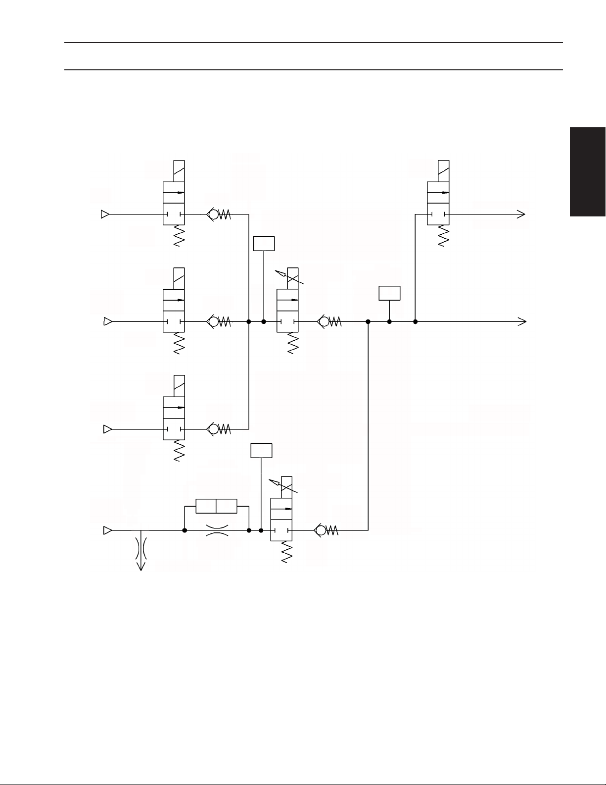
Plumbing Schematic
DESCRIPTION
DESCRIPTION
Ar
H35
N2/O2/Air
V1
V2
V3
PT1
PT2
PV1
V4
Exhaust Port
PT3
Plasma Gas
N2/O2/Air
0.5mm
Purge Orice
∆P
P
P
1
2
PV2
PT = Pressure Transducer
PV = Proportional Valve
45
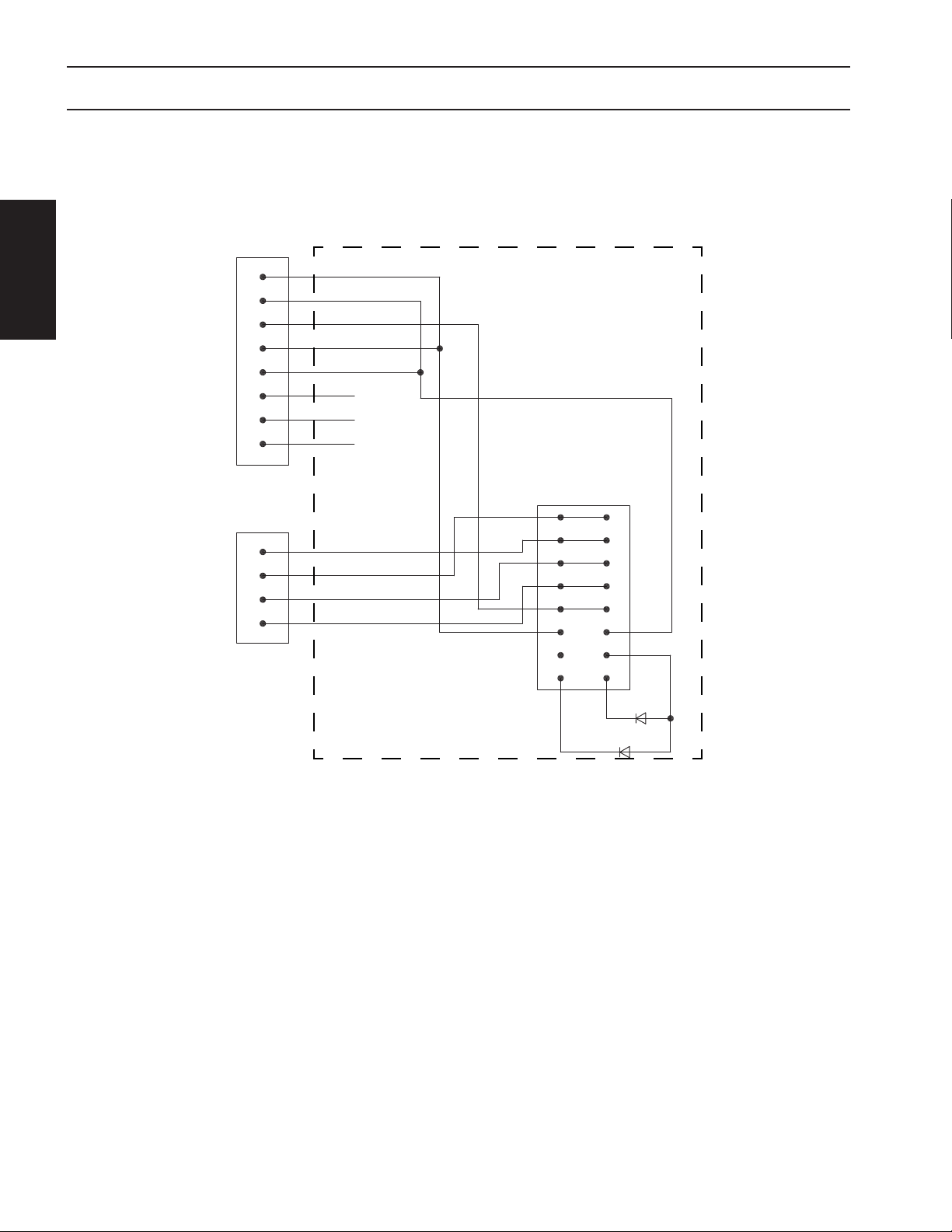
DESCRIPTION
Electrical Schematic
Con 1
1
CAN
2
3
4
5
6
7
8
DESCRIPTION
Con 2
1
2
3
POWER
4
CAN H Out
CAN L Out
CAN Gnd
CAN H In
CAN L In
NC
NC
NC
24VAC In
24VAC In
-24VDC In
+24VDC In
CO 1
1
3
5
7
9
11
13
15 16
2
4
6
8
10
12
14
LED 1
46
LED 2

DESCRIPTION
Connections
There are two cables connected to the Plasmas Gas Box: one is 24V power, the other is CAN. There are four gas
inputs (Argon, H35, PG1 and PG2) and one gas output (PG). The gas ttings are listed below.
Note:
Chassis must be connected to the machine ground.
DESCRIPTION
Gas Fitting
Argon 1/8” NPT x “A” Inert Gas RH Female 631475
H-35 1/4” NPT x “B” Fuel LH Male 3390
Inputs
PG1 1/4” NPT x “B” Inert Gas RH Female 74S76
PG2 1/4” NPT x “B” Oxygen RH Male 3389
Output PG
Connection, Male
0.125NPT to "A" Size
ESAB
P/N
20 64113
Troubleshooting
The Plasma Gas Control has two visible LEDs that indicate its’ status. When the GREEN LED is on, this indicates
power is applied to the unit and the rate at which it is ashing shows the operational status of the unit (refer to
the chart below). If the Green LED is not ON, check the power cable, which should carry 24VDC and 24VAC from
the Shield Gas Control.
If the Yellow LED is not ON, either there is no power to the unit or the station is not selected.
The Plasma Gas Control is highly integrated and is treated as a “Black Box”. If one or more functions of the unit
stop working, the unit must be returned for repair. Contact technical support for troubleshooting and RMA assistance.
LED Status Meaning
OFF Power OFF
10% ON, 90% OFF Boot loader is running
Green
50% ON, 50% OFF Application is running
90% ON, 10% OFF Application is running, CAN is available
Yellow ON Station is selected
47

2.5 Shield Gas Control (SGC)
p/n 0558010155
DESCRIPTION
(See following component illustrations)
DESCRIPTION
Component Locator Designation
PT-36 Plasma
Torch/ Air
Curtain
ICH
Gas Controls Power Cable
CAN
Air
Air
N2
O2
CH4
H35
ARG
A
B
L
C
D
E
F
M
N
Shield
Gas
Control
Air Curtain Hose
K
Shield Gas Hose
J
I
PG1 (Air/N2/O2)
H
PG2 (Air/N2/O2)
G
Power
H35
ARG
CAN
Shield Gas Control Component Locator Designations
Note:
Refer to enclosed tables for all available hoses and cables.
Plasma Gas
Control
48

DESCRIPTION
B
I
E
C
D
F
M
A
DESCRIPTION
L
N
K
J
H
G
49

CAUTION
Voltage Select Switch
DESCRIPTION
(cover must be re-
moved to access
switch)
DESCRIPTION
Voltage Select Switch MUST be set to the proper input voltage (115
or 230 volts - default setting is 230 volts) before energizing system.
Failure to do so could result in personal injury or equipment damage.
50

DESCRIPTION
Functions and Features
The Shield Gas Control selects dierent gases (Air, N2, O2, CH4) to mix shield gas (SG), plasma gas 1 (PG1), and
plasma gas 2 (PG2). The selections are done through a group of solenoids integrated on a manifold. The CNC
sends commands through CAN-bus to operate all these solenoids. The gas output of the Shield Gas Control is
monitored and fed back through the CAN-bus to CNC for self-diagnosis. Also, the Shield Gas Control controls the
solenoid for operation of the Air Curtain.
The default power input to Shield Gas Control is 230VAC. However, the Shield Gas Control input power is customer selectable, between 115 VAC and 230 VAC. This is accomplished by changing the input power switch inside the Shield Gas Control. The Shield Gas Control provides 24VDC and 24VAC power for the Plasma Gas Control.
Note:
Pressure Regulator is factory set
for carbon steel at 40 psi (2.8 bar).
If cutting stainless steel or alumi-
num set at 20 psi (1.4 bar).
8.00”
(203.2 mm)
8.00”
(203.2 mm)
DESCRIPTION
Weight:
30.0 lbs. (13.6 kg)
Note:
For required gas specications see
manual 0558008682, Subsection 7.1
9.50”
(241.3 mm)
8.25”
(209.6 mm)
to bottom
feet
9.25”
(235.0 mm)
51

DESCRIPTION
Shield Gas Control Mounting Hole Locations (Bottom View)
5.00”
(127. 0m m)
2.25”
(57.2mm)
DESCRIPTION
1.75”
(44.5mm)
4.25”
(108.0mm)
M6 -1
Shield Gas Control Mounting Plate Hole Locations
p/n 0558008794
0.281
(7.1mm)
0.313”
(8.0mm)
0.50”
(12.7mm)
9.50”
(241.3mm)
5.75”
(146.0mm)
52

Plumbing Schematic
Air
N2
O2
S2,2
S2,1
S3,2
DESCRIPTION
PV1
Air
N2
PV2
O2
DESCRIPTION
∆P
P
P
1
2
SG1
PT
SG
∆P
P
P
1
2
SG2
CH4
S3,1
S0,1
S0,2
S0,3
S1,1
S1,2
S1,3
CH4
O2
N2
Air
O2
N2
Air
PT = Pressure Transducer
PV = Proportional Valve
PG1
PG2
Air
S4,1
Air Curtain
Air
53

DESCRIPTION
Electrical Schematic
2
1
3
4
Con 6
DESCRIPTION
Solenoid
Air Curtain
24VDC
AC2
AC1
DC Com
Regulator
+24VDC
24VAC
Transformer
Fan
CO 11
4
2
6
3
1
5
12
10
8
7
14
16
LED 2
9
13
11
15
LED 1
230VAC
115 VA C
Switch
54
Fuse
NC
2
1
3
Con 3
4
115 / 230VAC
CAN H In
CAN L In
CAN Gnd
CAN H Out
CAN L Out
NCNCNC
1
2
3
4
5
6
7
Con 1
8

DESCRIPTION
Connections
There are three cables connected to the Shield Gas Control. They are 115/230 VAC power input, 24V power
output, and CAN. There are ve gas inputs (Air, N2, O2, CH4 and Air Curtain), four gas outputs (SG, PG1, PG2 and
Air Curtain), and two outboard connections (H35 and Argon). The ve inputs and two outboard connections are
tted with porous bronze lters and "G-1/4" (BSPP) female RH or LH thread. Either of two adaptor tting kits are
available to adapt standard metric or CGA hose connections. The gas ttings and adaptors are listed below.
Note:
Chassis must be connected to the machine ground.
DESCRIPTION
Metric
Input
Adaptors
CGA
Input
Adaptors
Outputs
Gas Fitting
Air G-1/4” RH Male x G-1/4” RH Male 0558010163
N2 G-1/4” RH Male x G-1/4” RH Male 0558010163
O2 G-1/4” RH Male x G-1/4” RH Male 0558010163
CH4 G-1/4” LH Male x G-1/4” LH Male 0558010164
Air
Curtain
H-35
(outboard)
Argon
(outboard)
Air G-1/4” RH Male x “B” Air/Water RH Male 0558010165
N2 G-1/4” RH Male x “B” Inert Gas RH Female 0558010166
O2 G-1/4” RH Male x “B” Oxygen RH Male 0558010167
CH4 G-1/4” LH Male x “B” Fuel RH Male 0558010168
Air
Curtain
H-35
(outboard)
Argon
(outboard)
SG 1/4” NPT x 5/8"-18 LH Male 0558010223
PG1 1/4” NPT x “B” Inert Gas RH Female 74S76
PG2 1/4” NPT x “B” Oxygen RH Male 3389
Air
Curtain
H-35
(outboard)
Argon
(outboard)
G-1/4” RH Male x G-1/4” RH Male 0558010163
G-1/4” LH Male x G-1/4” LH Male 0558010164
G-1/4” RH Male x G-1/4” RH Male 0558010163
G-1/4” RH Male x “B” Air/Water RH Male 0558010165
G-1/4” LH Male x “B” Fuel RH Male 0558010168
G-1/4” RH Male x “B” Inert Gas RH Female 0558010166
1/4” NPT x “B” Inert Gas LH Female 11N16
1/8” NPT x “B” Fuel LH Male 11Z9 3
1/8” NPT x “A” Inert Gas RH Female 631475
ESAB
P/N
55

DESCRIPTION
Troubleshooting
On the Shield Gas Control, there are two LEDs displaying the status of the CAN-bus module. The states of these
lights are shown in the table below.
LED Status Meaning
DESCRIPTION
10% ON, 90% OFF Boot loader is running
Green
50% ON, 50% OFF Application is running
90% ON, 10% OFF Application is running, CAN is available
Yellow ON Station is selected
In normal operation, the green LED indicating the power must be ON. When the station is selected, the yellow
LED should be ON all the time; and green LED will ash 90% ON and 10% OFF. Otherwise, there is a problem.
1. If the green light is not on, check the power input (cale connection) and fuse.
2. If the yellow light is not on and the green light is on, check can-bus connection. Make sure the station is selected.
OFF Power OFF
Replacement Parts
The Shield Gas Control is highly integrated and only a few parts can be replaced by a qualied service engineer
or by the customer. These parts are listed below. Otherwise, the entire Shield Gas Control needs to return for
repair. It is recommended that customers contact Technical Support before attempting repairs on these units.
Item No. Description ESAB PN
1 Transformer 0558008612
2 Fan 0558008614
3 Fuse - T630mA 250V, 5 x 20mm 0558008613
4 Solenoid 6240 for Air Curtain 0558008615
5 Pressure Gauge 0558008616
6 Pressure Regulator 0558008617
56

DESCRIPTION
6
5
DESCRIPTION
1
4
3
2
57

DESCRIPTION
2.6 Remote Arc Starter (RAS)
p/n 05580 08150
The Remote Arc Starter is more commonly referred to as
the RAS Box. The RAS box serves as an interface between
the plasma controller and the EPP family of plasma power
supplies, helping to deliver a stable plasma arc. The RAS
DESCRIPTION
box also provides a voltage feedback to the plasma torch
lift. This voltage is used to regulate the torch height while
cutting, maintaining the proper height of the torch above
the work piece.
Within the RAS box there is an I/O module for communicating with the plasma controller, a High Frequency/Voltage Divider circuit board which provides pilot arc ionization and voltage divider functions to regulate torch height.
Coolant connections and torch power connections are made within the RAS box and provide an interface between the power supply, coolant circulator and the torch.
Specications
Dimensions: 8.75” (222.3 mm) high x 7.50” (190.5 mm) wide x 17.00” (431.8 mm) deep
Weight: 28.5 lbs. (12.9 kg)
Remote Arc Starter Connections
G, H
EF
Chassis must be connected to
A
B
the machine ground.
Letter Description
C
D
J
A 3 Pin Voltage Divider Connection to the Lift
B 8 Pin Can Bus Connection to the CNC or Interface
C 24 Pin Amphenol Power Supply Connection
D E-Stop
E Coolant Inlet - Flowing to the Torch
Coolant Return - Flowing back to the Coolant Circu-
F
G, H Strain Relief Fittings
I Torch Shroud Connection
J Machine Ground Connection
Note:
lator from the Torch
58
I

DESCRIPTION
RAS Box Mounting Dimensions
The box has four M6 x 1 threaded mounting holes shown in pattern below.
If fasteners are threaded into the box from below, the length of the fasteners
CAUTION
5.00”
(12 7.0 0 mm)
must not allow them to extend more than 0.25” beyond the edge of the internal
female threads. If fasteners are too long they can interfere with the components
inside the box.
DESCRIPTION
1.00”
(2.54 mm)
2.75”
(69.85 mm)
RAS Box Mounting Plate Dimensions
p/n 0558008461
8.75"
(222.3 mm)
3.25"
7.50"
(190 .5 mm)
(82.6 mm)
6.50"
(165.1 m m)
13.75”
(349.25 mm)
18. 50"
(469.9 mm)
17. 50"
(444.5 mm)
59

2.7 PT-36 Plasma Torch
p/n 0558008300
The PT-36 Mechanized Plasmarc Cutting Torch is a
plasma arc torch factory assembled to provide torch
component concentricity and consistent cutting accuracy.
DESCRIPTION
7.54"
(191. 5 mm)
DESCRIPTION
(50.8 mm)
9.13"
(231.9 mm)
6.17"
(156.7 mm)
10.50" (266.7 mm)
Length of Sleeve
Specications
Type: Water cooled, Dual gas, mechanized plasmarc cutting torch
Current Rating: 1000 Amps @ 100% duty cycle
Mounting Diameter: 2 “(50.8 mm)
Length of Torch without leads: 16.7 “(42 cm)
IEC 60974-7 Voltage Rating: 500 volts peak
Striking Voltage (maximum value of HI-FREQUENCY voltage): 8000 VAC
Minimum Coolant Flowrate: 1.3 GPM (5.9 L/min)
Minimum Coolant Pressure at Inlet: 175 psig (12.1 bar)
Maximum Coolant Pressure at Inlet: 200 psig (13.8 bar)
Minimum Acceptable Rating of Coolant Recirculator: 16,830 BTU/HR (4.9 kW) at High Coolant Temperature -
Ambient = 45°F (25°C) and 1.6 USGPM (6 L/min)
Maximum Safe Gas Pressures at Inlets to Torch: 125 psig (8.6 bar)
Safety Interlocks: This torch is intended for use with ESAB plasmarc cutting systems and controls employing a
water ow switch on the coolant return line from the torch. Removal of the nozzle retaining cup to service
the torch breaks the coolant return path.
2.00"
60

2.8 Air Curtain (A/C)
DESCRIPTION
DESCRIPTION
p/n 37440
The Air Curtain is a device used to improve the performance of plasma arc when cutting underwater. The device
mounts onto the torch and produces a curtain of air. This allows the plasma arc to operate in a relatively dry zone
to reduce noise, fume, and arc radiation, even though the torch has been submerged.
The Air Curtain requires a source of compressed air that needs to be clean, dry and oil-free. It should be delivered
at 80 psi @ 1200 cfh (5.5 bar @ 34 CMH).
61

DESCRIPTION
2.9 Water Injection Control (WIC)
p/n 0558009370
The Water Injection Control (WIC) regulates the ow of cut water
supplied to the plasma torch. This water is used as a shield in
the cutting process. This shield assists in forming the plasma arc
and also cools the cut surface. The selection and output of cut
DESCRIPTION
water is performed and controlled by the CNC. The WIC consists
of a water regulator, pump and a closed feedback loop between
proportional valve and ow sensor. This is controlled by a local
Process Control Unit (PCU). The PCU communicates via CAN to
the ICH while controlling the proportional and solenoid valves.
The WIC is monitored and sends feedback signals through the CAN bus to the ICH for diagnostic purposes.
Specications
Dimensions (Electrical module) 163 mm x 307 mm x 163 mm (6.4 in x 12.1 in x 6.4 in)
Dimensions (Pump Module) 465 mm x 465 mm x 218 mm (18.3 in x 18.3 in x 8.6 in)
Weight (Electrical module) 15 lb. dry (6.8 kg)
Weight (Pump Module) 60 lb. dry (27.2 kg)
Tap water with an allowable water hardness of <2 ppm as CaCO3 and Conductivity: Re-
Water Requirements
Air Supply (anti-freezing function) 250 CFH @ 80 psi (7.1 cmh @ 5.5 bar)
Pump
Motor
Pressure Regulator
Pressure Transducer
Proportional Valve
Flow Sensor
Air Solenoid
sistivity must be at least 200,000 ohm/cm, Conductivity can be no more than (5 µ S/cm)
>200,000 ohms per inch, ltered at 5 microns. 1 gpm (3.8 l/min) minimum ow rate @ at
20 psi (1.4 bar).
Positive displacement, rotary vane with adjustable by-pass valve (250 psi / 17.2 bars maximum), CW rotation, Capacity: 1.33 GPM @ 150 psi (5.04 l/min @ 10.3 bar),
Nominal speed: 1725 rpm, Temperature rating: 150
1/2 HP, 230 VAC single phase, 60 Hz, 1725 RPM, 3.6A current,
Temperature rating: 150
Inlet water pressure: 100 psi (6.9 bar) maximum
Outlet water pressure: 20 psi (1.4 bar) factory set
Maximum pressure range: 0 - 200 psi (0 - 13.8 bar)
Temperature range: -40
Supply voltage: 24 VDC
Pressure signal output: 4 mA for 0 psi, 20 mA for 200 psi (13.8 bar). Regulated to 1 to 5 VDC
with 250 ohm resistor.
Supply voltage: 24 VDC
Full load current: 500 mA, Input control signal: 0-10 VDC.
Coil: Standard Voltage: 24 VDC, Operating current: 100-500 mA,
Valve: Orice size: 3/32”, Cv:0.14 (fully open)
Operating dierential pressure: 115 psi (8.0 bar) ; Max. ow 1.5 gpm
Maximum uid temperature: 150
Maximum operating pressure: 200 psi (13.8 bar),
Operating temperature: -4
mum, Output signal: 58 - 575 Hz, Flow range: 0.13 - 1.3 gpm
Supply voltage: 24 VDC, Maximum operating pressure: 140 psi (9.7 bar) , Operating temperature: 32
o
- 77o F (0 - 25o C)
o
F (66o C)
o
- 257o F (-40
o
- 212o F (-20o - 100o C), Input power: 5 - 24 VDC @ 50 mA maxi-
o
- 125o C)
o
F (66o C)
o
F (66o C)
62

DESCRIPTION
2.10 Automatic Height Control (AHC)
p/n 0560947166
The B4 lift assembly provides vertical motion for the PT-36 plasma torch, using a typical motor, screw, and slide conguration. The motor turns an enclosed spindle screw,
which in turn raises/lowers the lifting plate along linear rails. Directional commands
given from the plasma controller determine the direction of the travel. Fixed limit
switches are included to prevent upper and lower lift’s over travel.
The lift assembly also contains components necessary to control height over work
surfaces; initial, piercing, and cutting heights are encoder controlled during the plasma cycle. During part production, height is automatically controlled by taking voltage measurements between the torch electrode and work surface.
The B4 lifts utilize an Omni Soft Touch® assembly to protect the system during station crashes. Proximity switches monitor torch position in the torch holder. If the
torch is jarred in any direction, the process will stop and an error report will be sent
to the controller.
DESCRIPTION
Specications
Dimensions:
6.0” (152.4 mm) wide x 8.5” (215.9 mm) deep x 31.5” (800.1 mm) high
Lift Speed: 315 IPM [8.0m per minute]
Vertical Travel: 8.00” [200.0 mm]
Approximate Weight including torch holder: 85 lbs. [38.5 kg]
Torch Barrel Size: 85.7 mm
IHS Accuracy: ± 0.5 mm
Component Tolerances
Encoder Accuracy: ± 0.25 mm
Voltage Accuracy: ± 1 volt
63

DESCRIPTION
B4 Mounting Dimensions
B4 lift hole patterns are provided below to aid end users in mounting the plasma station. An optional plasma
bracket/nut plate is available. For more specic details, please refer to the B4 Lift manual.
DESCRIPTION
2.50”
[63.5mm]
4.47”
[113.5mm]
(6) M8 x 1.25 x 40
Socket Head Cap Screws
4.13” [104.9mm]
3.64” [92.4mm]
0.49” [12.4mm]
0.53”
[13.5mm]
x6 M8x1.25 - 6H
THRU HOLES
5.00”
[127.0mm]
64
Recommended Monting Bracket/Nut Plate

DESCRIPTION
DESCRIPTION
65

DESCRIPTION
DESCRIPTION
66

INSTALLATION
SAFETY DESCRIPTION
INSTALLATION
OPERATION APPENDIX

INSTALLATION
INSTALLATION
68

INSTALLATION
3.0 Grounding
Introduction
Machine grounding is an important part of the installation process, which can be greatly simplied if prepared
in advance. The most dicult part of the grounding process is designing and installing a low impedance Earth
ground rod. However, the better the Earth ground rod, the less chance there is of having electromagnetic
interference problems after the installation is complete.
Most national electric codes address grounding for the purpose of re prevention and short circuit protection;
they do not address equipment protection and electromagnetic interference noise reduction. Therefore, this
manual presents more stringent requirements for machine grounding.
WARNING
Electric Shock Hazard.
Improper grounding can cause severe injury
or death.
Improper grounding can damage machine
electrical components.
Machine must be properly grounded before
putting it into service.
INSTALLATION
The cutting table must be connected to
machine earth grounding rod.
69

INSTALLATION
Grounding Overview
There are three parts to a ground system;
•Component or "chassis" ground
•Earth ground
•Protective Earth ground
Component grounding connects all pieces to a
single component, like the machine chassis, which
is then connected to a common point known as the
star point. This provides a path for electromagnetic
A common symbol used to identify
a chassis ground on drawings.
INSTALLATION
interference (EMI) from the enclosure to ground.
An earth ground provides a electromagnetic
interference (EMI) to return to its source.
A protective earth (PE) ground provides a safe path
for fault current. Without a properly grounded
system, an unintended path through people or
sensitive equipment may be found, resulting in
serious injury, death, and/or premature equipment
failure.
A common symbol used to identify
an earth ground on drawings.
A common symbol used to identify
a protective earth (PE) ground.
This section focuses on machines with a plasma
cutting system. Machines with plasma cutting
capability are particularly prone to electromagnetic
interference problems and often utilize dangerous
voltages and currents. All machines must have
electrical components grounded and attached to
an earth ground, regardless of process type (shape
cutting, marking, or other material preparation).
70

Basic Layout
INSTALLATION
The electrical ground layout is similar for both large and small machines. The chassis ground , plasma
positive electrical lead and the rail ground cables are attached to a common point on the cutting
table. This common connection is referred to as a star point (see illustration below). One cable connects
the star point to the Earth ground rod . The size of ground cables is dependant on the maximum current
output of the plasma power supply . Specication of cable sizes is discussed later in this manual. Some
country standards or directives require a separate ground rod for the plasma power supply. Consult your
machine schematics for more information.
6 8
7
1
5
9
4
3
INSTALLATION
Note: The three phase electrical input
to the plasma power supply must include
an electrical ground.
2
8
This illustration demonstrates multiple ground
cables fastened with a single bolt to create a star
point . The location of the star point on the
cutting table will vary.
8
71

INSTALLATION
Elements of a Ground System
The ground system consists of ve main components:
•plasma current return path
•plasma system safety ground
•utility power electrical ground
•cutting machine chassis ground
•rail system safety ground.
Ensure provisions are made during the installation for each of these elements for creating a complete ground
system.
INSTALLATION
Plasma Current Return Path
The return path ground cable is the most important element of the ground system. It completes the path for
the plasma current. Solid, low impedance, well maintained electrical connections are a necessity.
The plasma cutting current is generated by the plasma power supply . A welding cable carries this current
from the negative (-) connection in the plasma power supply through the x axis cable chain to the
torch. The current then arcs to the work piece on the cutting table. The current path must be closed so
that the current can easily return to its source. This is done by connecting the cutting table to the positive (+)
connection on the plasma power supply. If the return path ground cable is not connected, the plasma
system will not work. There will be no way for the arc to establish between the torch and the work piece. If
the cable is connected, but the connections have a very high resistance, it will limit the current of the arc, and
cause dangerous voltage levels between system components.
1
5
3
2
2
4
4
1
3
72
5

INSTALLATION
The only way to ensure that all components are at the same voltage level (same potential), and thus eliminate
the possibility of being shocked, is to ensure that all interconnections are making good electrical contact.
Good electrical contact requires that connections are made with bare metal to metal contact, the connections
are very tight, and are protected from rust and corrosion. Use a grinder or wire wheel to clean all paint, rust,
and dirt from the surface when connecting cable lugs to any metal surface. Use an electrical joint compound
between cable lugs and metal surfaces to prevent future rust and corrosion. Use the largest size bolts, nuts,
and washers possible, and tighten fully. Use lock washers to ensure that connections stay tight.
Plasma System Safety Ground
The plasma system safety ground (or ground rod)
serves several important purposes. It provides:
•Frame voltage for personnel safety by ensuring
that there are no potential dierences between
system components and building components.
INSTALLATION
•A stable signal reference for all digital and analog
electrical signals on the cutting machine.
•Helps control electromagnetic Interference (or
EMI).
•Provides a discharge path for short circuits and
high voltage spikes, such as those caused by
lightening strikes.
73

INSTALLATION
There are many misconceptions about the ground rod, and the role it plays in reducing electromagnetic
interference. In theory, the ground rod is present to eliminate possible potential dierences between
equipment and building structures. However many people believe that the ground rod allows all radio
frequency noise to be absorbed and disappear into the Earth. Experience has shown that a good ground
rod will eliminate radio frequency noise problems.
Misconception about Earth ground rods.
INSTALLATION
1
1
74

INSTALLATION
In reality the ground rod is providing a low impedance path by which noise currents may return to their
source .
2
Earth ground rod reality.
1
INSTALLATION
2
1
75
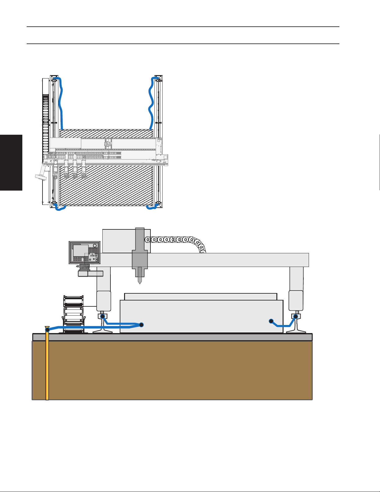
INSTALLATION
Rail System Safety Ground
The rail system safety ground makes sure that the
entire rail is at ground potential, eliminating any
possible shock hazard, and providing backup for the
machine chassis ground in case of a plasma current
short circuit. All four corners of the rail system should
be connected to the cutting table.
INSTALLATION
76

INSTALLATION
Earth Ground Rod
The best way to make sure that your Earth ground connection is optimized is to enlist the services of a
professional. There are a number of engineering rms which specializes in designing and installing Earth
grounding systems. However, if this option cannot be used, then there are several things which can be done to
ensure that your Earth ground connection is good:
Ground Rod
The ground rod itself can be optimized in two ways: length and diameter. The longer the grounding rod,
the better the connection. The same is true for diameter: the larger the diameter, the better the connection.
However, if the soil resistance is very low, then a ground rod longer than 3m [10 feet] does not make a
signicant dierence. Since soil resistivity is rarely as good as it could be, a standard grounding rod should be
25mm [1 inch] in diameter and 6m [20 feet] long.
Soil Resistivity
Soil resistivity can be changed in two ways: by altering the mineral content, the moisture content, or both.
The ideal solution to poor soil resistivity is to excavate the immediate area and backll with conditioned soil
additives. In extremely dry areas, the moisture content can be improved by installing a drip system which
continually moisturizes the soil surrounding the ground rod. A crude way of aecting soil moisture and content
is to use salt water, or rock salt to condition the surrounding soil.
INSTALLATION
77

INSTALLATION
Utility Power Electrical Ground
The utility power electrical ground must accompany all 3 phase and single phase power feeds. This electrical
ground provides the proper reference for all incoming power. Failure to provide this ground is a violation of
most electrical codes, and a serious safety hazard.
Depending on the 3 phase power arrangement (either a “Delta” or a “Y”), the line to ground voltage may be
equal to, or less than the line to line voltage. A problem exists any time the line to ground voltage exceeds any
individual line to line voltage (dierence in potential). Contact your local utility company if you are not sure
that your 3 phase power has a proper electrical ground. Make sure that your electrical contractor properly
installs the electrical ground wire with all 3 phase and single phase power feeds.
The electrical ground must be connected to the appropriate terminal inside of the plasma power supply. Size
wire according to local electrical codes.
INSTALLATION
2
1
1
Utility Power Electrical Ground
2
3 Phase Electrical Supply
3
Plasma Power Supply
3
78

INSTALLATION
Multiple Ground Rods
There are a number of reasons why multiple ground rods should not be used. While installing multiple rods
may improve a safety ground or lightening ground, it oers no advantage for electromagnetic interference
reduction, and can cause more problems than it is worth.
The problem with multiple ground rods is that each rod uses an “interfacing Electromagnetic Interference
1.1
1
2
Multiple ground points can also create undetectable
“sneak” pathways for radio frequency noise currents,
actually causing more interference! Instead of
considering multiple ground rods, take steps to
make the single ground rod as good a ground
connection as possible.
l
sphere” of earth, having a radius of 1.1 times the length of the rod. Overlapping of these Electromagnetic
Interference spheres causes a loss in grounding eectiveness proportional to the amount of overlap.
INSTALLATION
l
1
2
Multiple ground rods should be avoided if possible.
However, if all other avenues have been explored
to lessen your systems’ electronic interferences,
multiple ground rods are an option.
Such a system should be installed by a professional
and the distance between the rods should exceed
2.5 l
2.5 times the length of the rods.
79

INSTALLATION
Machine Grounding Schematic
2
1
3
4
8
10
INSTALLATION
5
(+)
6
1
Main Control Enclosure
2
Component Enclosures
3
Main Star Ground
Rails
4
9
7
•All electrical enclosures bolted to the
machine chassis
•Machine chassis grounded to star point on
cutting table.
•Rails grounded to cutting table
Cutting Table
5
•Plasma ground connected to star point on
System Star Ground (on Table)
6
Earth Ground Rod
7
Plasma Power Supply
8
Plasma Power Supply Ground (required by EU
9
Standards)
Electrical System Ground
10
cutting table
•Earth ground rod connected to star point on
cutting table.
•A separate ground rod is required for the
plasma power supply by some regulations
and directives. Check with local regulations
to determine if this additional ground rod is
required.
80

INSTALLATION
Check upon receipt
1. Verify all the system components on your order have been received.
2. Inspect the system components for any physical damage that may have occurred during shipping. If
there is evidence of damage, please contact your supplier with the model number and serial number
from the nameplate.
Before Installation
All installation and service of the electrical and plumbing systems
WARNING
Locate the major components to the right position prior to making electrical, gas, and interface connections.
Refer to the system interconnection diagrams for major components placement. Ground all major components
to earth at one point. To prevent leaks, make sure to tighten all gas and water connections with specic torque.
must conform to national and local electrical and plumbing codes.
Installation should be performed only by qualied, licensed
personnel. Consult your local authorities for any regulation issues.
3.1 Placement of Power Supply
INSTALLATION
Failure to follow instructions could lead to death, injury or
WARNING
damaged property. Follow these instructions to prevent injury or
property damage. You must comply with local, state and national
electrical and safety codes.
•A minimum of 1 meter (3 ft.) clearance on front and back for cooling air ow.
•Plan for top panel and side panels having to be removed for maintenance, cleaning and inspection.
•Locate the power supply relatively close to a properly fused electrical power supply.
•Keep area beneath power supply clear for cooling air ow.
•Environment should be relatively free of dust, fumes and excessive heat. These factors will aect cooling
eciency.
Input Power Connection
Electric shock can kill! Provide maximum protection against
WARNING
Input power must be provided from a line (wall) disconnect switch that contains fuses or circuit breakers in accordance to local or state regulations.
electrical shock. Before any connections are made inside the
machine, open the line wall disconnect switch to turn power o.
Input Conductors
•Customer needs to supply the input conductors, which may consist either of heavy rubber covered copper
conductors (three power and one ground) or run in solid or exible conduit.
•Size of input conductors is dependent on the current. Please refer to the specic power supply manual for
the size on input conductors.
81

INSTALLATION
Input Connection Procedure
1. Remove cover panel.
2. Thread cables through the access opening.
3. Secure cables with strain relief at the access
opening.
4. Connect the ground lead to the stud on the chassis.
5. Connect the power leads to the primary terminals.
6. Connect the input conductors to the line (wall)
disconnect.
7. Before applying power, replace the cover panel.
INSTALLATION
Electric shock can kill! Dangerous voltage and current may be
present any time working around a plasma power source with
covers removed:
Connection example of EPP-360
Chassis Ground
Primary Terminals
WARNING
•DISCONNECT POWER SOURCE AT THE LINE (WALL) DISCONNECT.
•HAVE A QUALIFIED PERSON CHECK THE OUTPUT BUS BARS (POSITIVE
AND NEGATIVE) WITH A VOLTMETER.
Output Connection Procedure
1. Open access panel on the lower front of the
power source.
2. Thread output cables through the openings at
the bottom of the power source immediately
behind the front panel.
3. Connect cables to designated terminals
mounted inside the power source using UL
listed pressure wire connectors.
4. Close front access panel.
Workpiece connection
Connection example of EPP-360
82
Pilot Arc connection
Electrode connection

INSTALLATION
Interface Cables/Connections
Connection example of EPP-360
INSTALLATION
CNC Interface Cable
RAS Box front view
CNC Interface Cables
Part Number Length Part Number Length
0558004651 7.6m 0558004654 30.5m
0558004652 15.0m 0558003978 38.1m
0558004653 22.8m 0558004655 45.7m
Water Cooler Interface Cable
CC-11 rear view
Water Cooler Interface Cables
Part Number Length
0558004837 5.0m
0558004838 10.0m
0558004839 20.0m
83

INSTALLATION
3.2 Placement of CC-11 Coolant Circulator
Install the CC-11 in an appropriate location so as to maintain adequate and unrestricted airow into and out of
the cabinetry.
Input Power Connection
A 3-conductor power cable suitable to meet the required input power must be installed. The cable must have
0.25” (6.4 mm) ring lugs installed on the machine end. Connect the power leads to the L1 and L2 terminals and
the ground lead to the ground lug located on the base near the rear panel. A strain relief tting is provided to
feed a power cable through the rear panel of the cabinet. Please refer to the CC-11 Instruction manual for details.
Electrical installation must be in accordance with local electrical codes for this type of equipment.
Voltage link MUST be moved if equipment is operated at any voltage
CAUTION
INSTALLATION
other than 575V. Failure to move voltage link to location that matches input voltage can result in damage to equipment.
NOTE:
Voltage link is shipped in
this location which is for
575 volt operation.
Input Power Cable
L1 and L2 terminals
84
Typical connection for 460 VAC input
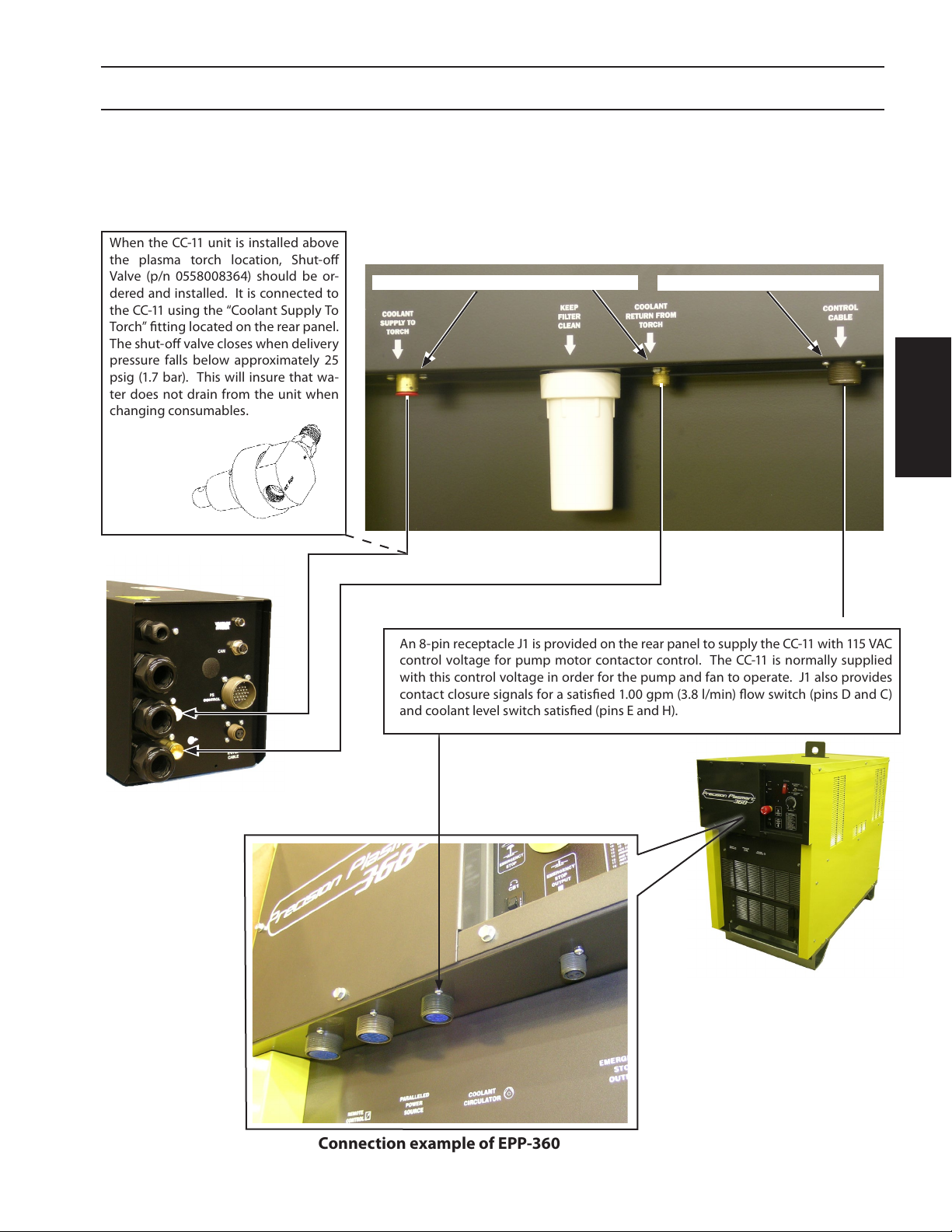
INSTALLATION
Coolant Connections and Optional Equipment
Connect the hoses to the CC-11 accordingly.
When the CC-11 unit is installed above
the plasma torch location, Shut-o
Valve (p/n 0558008364) should be or-
dered and installed. It is connected to
the CC-11 using the “Coolant Supply To
Torch” tting located on the rear panel.
The shut-o valve closes when delivery
pressure falls below approximately 25
psig (1.7 bar). This will insure that wa-
ter does not drain from the unit when
changing consumables.
Shut-o Valve
p/n 0558008364
CC-11 rear view
Coolant Connections Control Cable
INSTALLATION
An 8-pin receptacle J1 is provided on the rear panel to supply the CC-11 with 115 VAC
control voltage for pump motor contactor control. The CC-11 is normally supplied
with this control voltage in order for the pump and fan to operate. J1 also provides
contact closure signals for a satised 1.00 gpm (3.8 l/min) ow switch (pins D and C)
and coolant level switch satised (pins E and H).
RAS Box front view
Connection example of EPP-360
85

INSTALLATION
These connectors are located on the back of the unit. Connect the hoses to the CC-11 accordingly. The torch
hose ends should be tted with one 5/8"-18 male left-hand air / water hose and one 5/8"-18 female right-hand
air / water hose connector.
With the torch and the CC-11 connected, ll the reservoir with the specially formulated torch coolant.
Do not use regular anti-freeze solutions, such as for
an automobile, as the additives will harm the pump
and torch. ESAB P/N 0558004297 is recommended
for service down to 12° F (-11° C). ESAB P/N 156F05 is
recommended for service below 12° F (-11° C) to -34°
F (-36° C).
After lling the reservoir, run the pump with its cap
INSTALLATION
removed in order to purge air from the radiator, hoses, and torch. Re-check coolant level to ensure reservoir is lled. Replace reservoir cap after purging and
checking coolant level.
Coolant Connections
3.3 Placement of RAS Box
Connections on the RAS Box
1. Remove or unlock the cover screws and lift the box cover o to expose internal components.
The cover is grounded to the Remote Arc Starter Box internally with
WARNING
2. Power cables pass through the strain relief ttings.
a short ground wire. Remove cover carefully to avoid damage to the
wire or loosening of the ground wire.
Pilot Arc Cable enters through strain relief tting
to Voltage Divider (VDR)
to CAN
86
to PS Control
Coolant IN
to E-Stop
Coolant OUT
Power Source Cables enter through strain relief ttings

INSTALLATION
Buss Bar / Block
Nomex Insulation
Locking Screw
3. Strip back the insulation of the 4/0 (95 mm
4. Insert the 4/0 (95 mm
2
) cable in the buss bar/block hole until copper extends to the edge of the buss bar /
2
block.
5. Tighten the locking screw(s) down on the cable.
Connection for Pilot Arc Cable
) cable, approximately 38 mm.
INSTALLATION
Standard VDR Cable
VDR Cable (with free end)
6. If a non-ESAB lifter is to be used with a system the supplied VDR cable will only have a connector on one
end. The other end of the cable will have no connector. The end with the supplied connector is to be
connected to the RAS box to its corresponding socket which is labeled “Voltage Divider.”
The free end of the VDR cable will be connected to the lifter. Although this is a three conductor cable,
only two of the wires are used, BRN (VDR - ) and BLU (WORK). The black wire is a spare and is to be
terminated and capped inside of the lifter. The corresponding pin at the RAS box comes terminated from
the factory. The RAS box is not to be modied.
It is imperative that the BLUE wire be connected to ground. The BROWN wire is the VDR(-) output.
Customer
Supplied
Lifter
Ground
in Lifter is
VDR (Voltage Divider Cable)
required for
reference
87

INSTALLATION
3.4 Torch Connections
Torch hook-up requires the connection of power cables / coolant hoses, pilot arc cable and chassis ground. On
the PT-36 torch, the coolant hoses from the RAS box to the torch also carry electrode power.
The pilot arc cable is connected inside the arc starter box. The pilot arc cable also has a green/yellow wire that is
connected to a grounding stud.
Power Cable /
Coolant Connections
Pilot Arc Connection
INSTALLATION
Power Cable /
Ground
Stud
Chassis
Ground
Wire
Pilot
Arc Cable
Coolant
88
PG Hose
SG Hose

INSTALLATION
3.5 Mounting Torch to Machine
Clamping on Torch body may cause dangerous current to ow
WARNING
Mount torch on insulated sleeve here.
through machine chassis.
•Do not mount on stainless steel torch body.
•Torch body is electrically insulated, however high frequency start
current may arc through to nd a ground.
•Clamping near torch body may result in arcing between body and
DO NOT mount
on steel torch
body here.
machine.
•When this arcing occurs, torch body may require non-warranty
replacement.
•Damage to machine components may result.
INSTALLATION
•Clamp only on insulated torch sleeve (directly above label) not less
than 1.25" (31.75 mm) from the torch end of the sleeve.
•PT-36 Torch has an outside diameter of 50mm for standard
mounting.
89
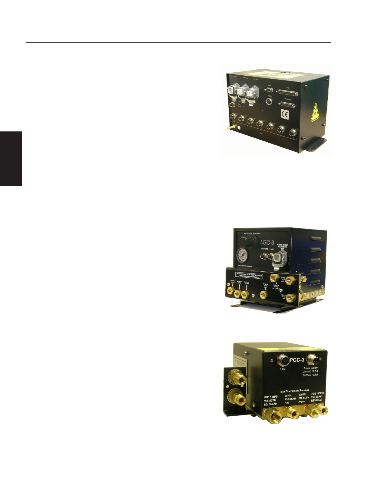
INSTALLATION
3.6 Placement of ICH
The ICH should be located close to the operator for easy access.
Connect required CAN cables between ICH and other CAN nodes,
such as Remote Arc Starter (RAS), B4 lifter, if applicable. CAN connection is always made from left to right, if one node is removed
from CAN bus, all nodes on the right need to be shifted to left. After
connecting all CAN nodes, a terminator is required. Leave all unused
CAN ports open.
Connect DB37 cable to port “CNC” on ICH. The other side of DB37,
is connected to the customer’s CNC via a male DB37 connector. An
optional breakout board may be used.
INSTALLATION
Connect power from ICH to SGC and B4 lifter, if applicable. Make sure the power switch on ICH is o.
Connect power to ICH box.
3.7 Placement of SGC
The Shield Gas Box selects dierent gases (Air, N2, O2,
CH4) to mix shield gas (SG), plasma gas 1 (PG1), and
plasma gas 2 (PG2). The selections are done through
a group of solenoids integrated on a manifold. The
CNC sends commands through CAN-bus to operate
all these solenoids. The gas output of the Shield Gas
Box is monitored and fed back through the CAN-bus
to CNC for self-diagnosis. Also, the Shield Gas Box
controls the solenoid for operation of the Air Curtain.
3.8 Placement of PGC
The Plasma Gas Box regulates the output of the plasma gas (PG) selected from the four gas inlets (Argon, H35, PG1 and PG2). It is powered by 24 Volts (AC and DC) from the Shield Gas Box and receives
commands via the CAN-bus directly from the CNC.
90

INSTALLATION
Individual Component Connections
Part numbers and lengths for the cables shown below are provided on the following page.
A
B
ICH back
INSTALLATION
SGC back
PGC front
“A” - Power cable from ICH to SGC (115/230V)
Part Number Length Part Number Length
0560947962 1m (3.3’) 0560947088 5m (16’)
0560946776 2m (6.4’) 0560947089 6m (19’)
0560947964 3m (10’) 0560947090 7m (23’)
0560947087 4m (13’ )
“C” - Power cable SGC to PGC (24 VAC/DC)
Part Number Length Part Number Length
0560947079 1.5m (5’) 0560947064 8m (26’)
0560947080 3m (10’) 0560947065 9m (30’)
0560947061 4m (13’) 0560947082 10m (33’)
0560947081 5m (16’) 0560946780 12.8m (42')
0560947062 6m (19 ’) 0560947066 15m (49 ’)
0560947063 7m (23’) 0560947083 20m (66’)
B
C
SGC back
“B” - CAN cable from ICH to PGC/SGC
Part Number Length Part Number Length
0558008464 1m (3.3’) 0558008473 10 m (33’)
0558008465 2m (6.5’) 0558008474 11m (36’ )
0558008466 3m (10’) 0558008475 12m (39’ )
0558008467 4m (13’ ) 0558008476 13m (43’ )
0558008468 5m (16’ ) 0558008477 14m (46’)
0558008469 6m (19 ’) 0558008478 15m (49 ’)
0558008470 7m (23’) 0558008479 20m (66’)
0558008471 8m (26’) 0558008809 25m (82')
0558008472 9m (30’) 0558008480 36m (118')
91
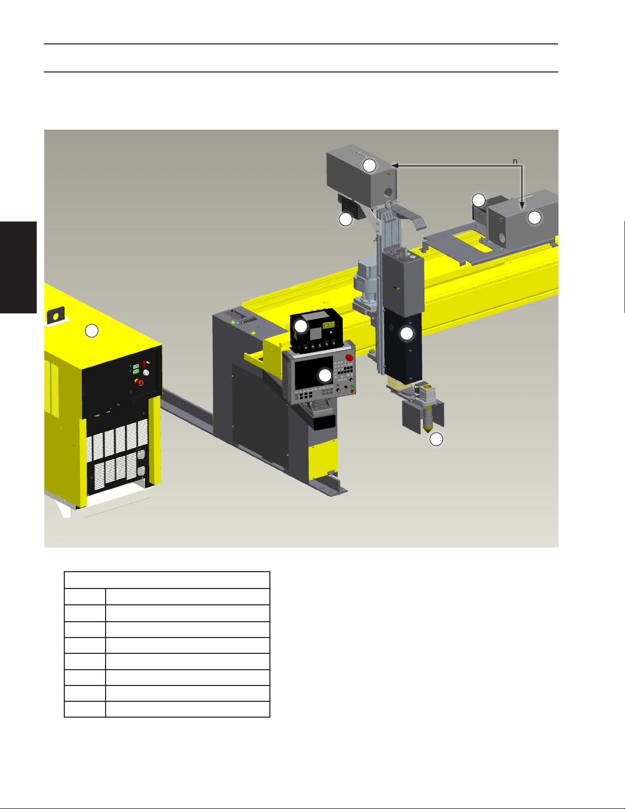
INSTALLATION
Component Placement Example
6
5
INSTALLATION
7
2
1
alternative mounting location
8
6
4
3
92
Components
1 CNC
2
3 PT-36 Torch
4 B4 Lift
5
6 Remote Arc Starter Box (RAS)
7 Power Supply
8 Shield Gas Control (SGC)
Interface Control Hub (ICH)
Plasma Gas Control (PGC)

INSTALLATION
INSTALLATION
93

INSTALLATION
INSTALLATION
94

SAFETY
DESCRIPTION INSTALLATION
OPERATION
OPERATION
APPENDIX

OPERATION
OPERATION
96

OPERATION
4.0 Interface Control Hub
The ICH (Interface Control Hub) is used to interface the ESAB m3 Process Control with the customer CNC using
RS232/RS422/RS485 and digital I/O.
Operation of the m3 G2 system can be made via the ICH (Interface Control Hub) in the following modes.
1. Remote mode without serial communications. (Default)
2. Remote mode with serial communications.
3. Local mode - diagnostics only.
The following pages describe how to operate the ICH.
OPERATION
97

OPERATION
7
6
OPERATION
1 2 3 4 5
ICH front view
8 9 10 11
16
15
GND
12
13
14
Note:
Chassis must be connected
to the machine ground.
98
ICH back view

OPERATION
4.1 Operation
ICH Connectors
Item Number Item Description
In Local mode, this switch will start the plasma process. If the Gas Test switch
1 Plasma Start
2 Gas Test
3 Local/Remote
4 Station Select
5 Screen Select This switch will allow the user to select dierent screens.
6
7 Power Switch This switch will turn on the Interface Control Hub.
8 Input Power
9 AHC Power Power connection for an ESAB lift (B4 or A6).
10 Gas Power
11 RS232 RS232 protocol for remote control if needed.
12 ASIOB1 ASIOB1 protocol for retrotting older ESAB systems.
13 CNC
14 AUX Control DB25 connector for auxiliary options such as Air Curtain.
15 CAN Vision 5x Not used.
16 Fuses Replace fuses with same type and size.
Encoder Wheel
with Push Button
is set to on, then the process will go into TEST Mode. In TEST Mode the power
supply faults, errors, and warnings are ignored while at the same time the steps
for starting the power supply and turning HF on are skipped.
In Local mode, this switch will start the plasma gas and shield gas at their start
values. If the plasma start switch is turned on after this one, the plasma process
will start in TEST mode.
This switch will change the ICH system from being remotely controlled, via the
serial communications and digital inputs from the CNC, to locally controlled via
the switches on the Interface Control Hub.
This switch is a momentary switch which will change the station of which the
information on the screen is displaying. If the system is in local mode, then the
station selected will change to only the station displayed.
This only has an eect in local mode under normal operation, when communication is set to none, and in the set up mode. This wheel will allow you to
change the parameter the cursor is currently on. The button will also allow you
to see a more detailed error message when on the error log screen.
To work the wheel for editing a parameter, push the wheel, move the wheel to
change the value, and then press the wheel again to lock in the value.
Customer supplied input power to ICH. See specications for power requirements.
Power connection to the Shield Gas Control (SGC), which provides 24 VAC/DC
to the Plasma Gas Control (PGC).
DB37 connector to interface to customer I/O. This also has the RS422/485 connections.
OPERATION
99

OPERATION
Display Screens
Startup Screen
On powerup the ICH screen displays the following information for 3 seconds:
Software version
OPERATION
Editing a Parameter on the Display
Only available when communication is set to none or Local/Remote switch is set to Local.
Use the encoder wheel to scroll to the parameter.
1.
2. Push the wheel.
3. Turn the wheel to edit the value.
4. Push the wheel again to lock the value.
Gas Selection Screen
L = Local
C = Cutting
M = Marking
Parameter Set Type
Gas Selection
Input Gas 1 (bar)
Input Gas 2 (bar)
Out Pressure (bar)
PG2 Flow (cmh)
100
Out SG1 Flow (cmh)
Out SG2 Flow (cmh)
Current (amps)
Arc Voltage (volts)
 Loading...