

Page 1
®
B4 Heavy Duty Lift Assembly
m3 CAN Plasma System
Instruction Manual
Form Number 0560946015 REV04
Date: 02 / 2 5 / 11
Page 2

BE SURE THIS INFORMATION REACHES THE OPERATOR.
YOU CAN GET EXTRA COPIES THROUGH YOUR SUPPLIER.
CAUTION
These INSTRUCTIONS are for experienced operators; if you are not fully familiar with the
principles of operation and safe practices for arc welding and cutting equipment, we urge
you to read booklet “Precautions and Safe Practices for Arc Welding, Cutting, and
Gouging” (Form 52-529). Do NOT permit untrained persons to install, operate, or maintain
this equipment. Do NOT attempt to install or operate this equipment until you have read
and fully understand these instructions. If you do not fully understand these instructions,
contact your supplier for further information. Be sure to read Safety Precautions before
installing or operating this equipment.
USER RESPONSIBILITY
This equipment will perform in conformity with the description thereof contained in this manual and accompanying labels and/or inserts when installed, operated, maintained and repaired in accordance with the instructions provided. This equipment must be checked periodically. Malfunctioning or poorly maintained equipment
should not be used. Parts that are broken, missing, worn, distorted or contaminated should be replaced immediately. Should such repair or replacement become necessary, the manufacturer recommends that a telephone
or written request for service advice be made to the Authorized Distributor from whom it was purchased.
This equipment or any of its parts should not be altered without the prior written approval of the manufacturer.
The user of this equipment shall have the sole responsibility for any malfunction which results from improper
use, faulty maintenance, damage, improper repair or alteration by anyone other than the manufacturer or a service facility designated by the manufacturer.
READ AND UNDERSTAND THE INSTRUCTION MANUAL BEFORE INSTALLING OR OPERATING.
PROTECT YOURSELF AND OTHERS!
Page 3

B4-200 Plasma Lift Assembly
Contents
Safety
Precautions ������������������������������������������������������������������������������������������������������������������������������������������������������������������� 3
Enclosure Class ������������������������������������������������������������������������������������������������������������������������������������������������������������� 4
General Safety Recommendations ��������������������������������������������������������������������������������������������������������������������������� 5
Description
Introduction ������������������������������������������������������������������������������������������������������������������������������������������������������������������ 7
Major Components - B4 Lift ��������������������������������������������������������������������������������������������������������������������������������������� 8
Installation
Mounting ���������������������������������������������������������������������������������������������������������������������������������������������������������������������� 9
Electrical Interfacing ������������������������������������������������������������������������������������������������������������������������������������������������� 10
Station Grounding ����������������������������������������������������������������������������������������������������������������������������������������������������� 13
Maintenance
Preventative Maintenance Schedule ���������������������������������������������������������������������������������������������������������������������� 14
Daily ������������������������������������������������������������������������������������������������������������������������������������������������������������������������������������������������� 14
Weekly ��������������������������������������������������������������������������������������������������������������������������������������������������������������������������������������������15
Monthly ������������������������������������������������������������������������������������������������������������������������������������������������������������������������������������������15
Semi-Annually ������������������������������������������������������������������������������������������������������������������������������������������������������������������������������ 15
Maintenance Procedures
B4-200 Lift ������������������������������������������������������������������������������������������������������������������������������������������������������������������� 17
Introduction ����������������������������������������������������������������������������������������������������������������������������������������������������������������������������������17
Lift Cleaning and Lubrication ������������������������������������������������������������������������������������������������������������������������������������������������� 17
B4 Lift Part Removal and Replacement ������������������������������������������������������������������������������������������������������������������������������� 19
1
Page 4

B4-200 Plasma Lift Assembly
Omni Crash Protection ��������������������������������������������������������������������������������������������������������������������������������������������� 26
Description ������������������������������������������������������������������������������������������������������������������������������������������������������������������������������������ 26
Function Description ����������������������������������������������������������������������������������������������������������������������������������������������������������������� 27
Replacing / Adjusting the Omni® Sensor ����������������������������������������������������������������������������������������������������������������������������28
Omni® Sensor Installation ��������������������������������������������������������������������������������������������������������������������������������������������������������29
Omni® Mechanical Alignment ������������������������������������������������������������������������������������������������������������������������������������������������32
Disassembly ����������������������������������������������������������������������������������������������������������������������������������������������������������������������������������33
Lubrication ������������������������������������������������������������������������������������������������������������������������������������������������������������������������������������ 34
Technical Descriptions and Troubleshooting
Encoder Height Control �������������������������������������������������������������������������������������������������������������������������������������������� 35
Introduction ����������������������������������������������������������������������������������������������������������������������������������������������������������������������������������35
Encoder Station Constant (STA�kon) Reference Chart ����������������������������������������������������������������������������������������������������36
Setting Station Constants using distance calculations �������������������������������������������������������������������������������������������������36
AVHC Introduction and Oset Adjustment ���������������������������������������������������������������������������������������������������������� 37
Basic B4 Lift Assembly Troubleshooting ��������������������������������������������������������������������������������������������������������������� 38
Yaskawa Junma Servopack™ Alarm Indicators ����������������������������������������������������������������������������������������������������� 39
2
Page 5

B4-200 Plasma Lift Assembly
Safety
Precautions
Users of ESAB welding and plasma cutting
equipment have ultimate responsibility for ensuring
that anyone who works on or near the equipment
observes all relevant safety precautions� Safety
precautions must meet requirements that apply to
this type of welding or plasma cutting equipment�
All work must be carried out by trained personnel
well acquainted with operation of welding or
plasma cutting equipment� Incorrect operation of
equipment may lead to hazardous situations which
can result in injury to the operator and damage to
equipment� The following recommendations should
be observed in addition to standard regulations that
apply to the workplace�
1�
Anyone who uses welding or plasma cutting
equipment must be familiar with:
…
Proper operation�
Location of emergency stops� …
Designed function� …
Relevant safety precautions� …
Welding and/or plasma cutting� …
Operators must ensure that:2�
No unauthorized person within the working …
area of equipment when it is started up�
…
No one is unprotected when plasma arc is
struck�
3�
The workplace must be:
Suitable and …
Free from drafts� …
Personal safety equipment:4�
Always wear recommended personal safety …
equipment, such as safety glasses, ame proof
clothing, and safety gloves�
…
Do not wear loose tting items, such as
scarves, bracelets, rings, etc�, which could become
trapped or cause burns�
3
Page 6

B4-200 Plasma Lift Assembly
General precautions:5�
Make sure return cable is connected securely� …
Work performed on high voltage equipment …
may only be carried out by a qualied
electrician�
…
Appropriate re extinguishing equipment
must be clearly marked and close at hand�
… must not be
Lubrication and maintenance
carried out on equipment during operation�
Enclosure Class
Maximum
Tilt Allowed
15°
CAUTION
The IP code indicates the enclosure class, i�e� the
degree of protection against penetration by solid
objects or water� Protection is provided against
touch with a nger, penetration of solid objects
greater than 12mm and against spraying water up to
60 degrees from vertical� Equipment marked IP23S
may be stored, but is not intended to be used outside during precipitation unless sheltered�
If equipment is placed on a surface that slopes
more than 15°, toppling over may occur.
Personal injury and/or signicant damage to
equipment is possible.
WARNING
4
WELDING AND PLASMA CUTTING CAN
CAUSE INJURY TO YOURSELF AND
OTHERS. TAKE PRECAUTIONS WHEN
WELDING OR CUTTING. ASK FOR YOUR
EMPLOYER’S SAFETY PRACTICES WHICH
SHOULD BE BASED ON MANUFACTURERS’
HAZARD DATA.
Page 7

B4-200 Plasma Lift Assembly
General Safety
Recommendations
ELECTRIC SHOCK - Can kill�
Ground welding or plasma cutting units in
•
accordance with applicable standards�
•
Do not touch live electrical parts or electrodes
with bare skin, wet gloves, or wet clothing�
•
Insulate yourself from earth ground and the
workpiece�
•
Ensure your working stance is safe�
FUMES AND GASES - Can be dangerous to health�
•
Keep your head out of the fumes�
Use ventilation, extraction at the arc, or both, to •
take fumes and gases away from your breathing
zone and the general area�
CAUTION
ARC RAYS - Can injure eyes and burn skin�
•
Protect your eyes and body, using correct
welding/plasma cutting screens and lter lens�
•
Wear protective clothing�
Protect bystanders with suitable screens or •
curtains�
FIRE HAZARD - Sparks (spatter) can cause re� Make
sure that there are no ammable materials nearby�
NOISE - Excessive noise can damage hearing�
Protect your ears, using ear protection�
•
Warn bystanders of the risk�•
MALFUNCTION - Call for expert assistance in the
event of malfunction�
READ AND UNDERSTAND THE INSTRUCTION
MANUAL BEFORE INSTALLING OR OPERATING.
PROTECT YOURSELF AND OTHERS!
5
Page 8

B4-200 Plasma Lift Assembly
CAUTION
To avoid personal injury and/or equipment damage, lift using method and attachment points
shown below.
6
Page 9

B4-200 Plasma Lift Assembly
Description
Introduction
The B4-200 lift assembly provides vertical motion for
the PT-36 plasma torch, using a typical motor, screw,
and slide conguration� The motor turns an enclosed
spindle screw, which in turn raises/lowers the lifting
plate along linear rails� Directional commands given
from CNC determines direction of lift travel� Fixed
limit switches are included to prevent upper and
lower over travel�
The lift assembly also contains components
necessary to control height over work surfaces;
initial, piercing, and cornering heights are encodercontrolled during the plasma cycle through use
of SDP/TDF les� During part production, stando
is automatically controlled by taking voltage
measurements between torch nozzle and work
surface�
Finally, the B4 lifts include an Omni Soft Touch®
assembly to protect the system during station
crashes� Proximity switches monitor torch position in
the torch holder� If the torch is jarred in any direction,
process movement will stop and an error report will
be sent to CNC� The Illustration on following page
will detail major lift components and their location�
For illustrated part breakdowns, see end section of
this manual�
7
Page 10

B4-200 Plasma Lift Assembly
1
2
3
4
5
6
7
8
9
10
11
Major Components - B4 Lift
Remote Arc Starter box
Torch Bundle Guide ring
B4 Lift Mounting bracket (option)
Electrical Soft Touch box
B4 Lift Electronics Enclosure
Plasma Gas box
B4 Lift Assembly
OMNI Mounting bracket
Electrical Soft Touch wire (option)
OMNI Soft Touch® assembly
PT-36 m3C Torch
Technical Specications
Lift Speed:• 315 IPM [8.0m per minute]
•
Vertical Travel: 8.00” [200.0 mm]
Approximate Weight of Lift Assembly •
including torch holder: 85 lbs. [38.5 kg]
•
Torch Barrel Size: 85.7 mm
Component Tolerances•
IHS Accuracy: ± 0.5 mm …
Encoder Accuracy: ± 0.25 mm …
Voltage Accuracy: ± 1 volt …
8
Page 11

B4-200 Plasma Lift Assembly
5.00”
[127.0mm]
4.13” [104.9mm]
0.49” [12.4mm]
3.64” [92.4mm]
4.47”
[113.5mm]
x6 M8x1.25 - 6H
THRU HOLES
0.53”
[13.5mm]
2.50”
[63.5mm]
Installation
Mounting
B4 lift hole patterns are provided below to aid end
users in mounting the plasma station. An optional
plasma bracket/nut plate are available as an option;
part numbers are included in Replacement Parts
section of this manual.
(6) M8 x 1.25 x 40
Socket Head Cap Screws
B4-200 Lift Assembly dimensions
9
Page 12

B4-200 Plasma Lift Assembly
NOTICE
Torpedo Level
Ensure lift assembly is mounted
plumb; use a torpedo level and
adjust mounting bolts as needed.
Electrical Interfacing
After lift assembly and electrical enclosure have
been mounted, make the following electrical
connections:
m3 CAN OEM Interface Box
NOTICE
Lift Input Power1� (4 pin, male_female):
connection is from control interface box AHC
Power to lift electrical enclosure SB2�
2� (M12, 8 pin, male_male):
ACON cable
connection is from control interface box CAN #
connector to lift electrical enclosure SB1�
CAN # connection used will vary
depending on your system conguration.
See System Interconnection manual (PN
0558008527) to determine your system
conguration.
Crash Protection cable3� (M12, 8 pin male_
female): connection is from lift electrical
enclosure SB3 to Omni® Soft Touch proximity
sensor�
10
Page 13

Lift Electrical Enclosure
1
2
3
A
3A2
1
connection guide
B4-200 Plasma Lift Assembly
SB2 - Input Power
SB1 - ACON
SB3 - Crash Protection OR
Soft Touch Interconnection
SB5 - VDR (RAS)
11
Page 14

B4-200 Plasma Lift Assembly
9
7
8
NOTICE
The following connections will need to be made if
your plasma station has electrical soft touch option
installed:
4� (M12, 8 pin
Soft Touch Interconnection cable
female-female): connection is from lift electrical
enclosure SB3 to soft touch enclosure ST1�
The Soft Touch Interconnection cable (#4)
will replace the Crash Protection cable (#3)
on plasma stations utilizing electrical soft
touch option.
Electrical Soft Touch Enclosure
Connection Guide
Soft Touch Proximity cable5� (M8 female socket_
free wire end): connection is from X3 (inside
soft touch electrical enclosure) to Omni® Soft
Touch proximity sensor�
6� (14-16AWG, in-line terminal_
Torch Touch wire
torch clamp): connection is from soft touch
board X4 to torch clamping ring� Attach this
clamping ring to metal portion of PT-36 torch
body�
Soft touch enclosure lid was made transparent to show box detail.
12
Page 15

B4-200 Plasma Lift Assembly
CAUTION
DO NOT cut under water if electrical
soft touch option is installed on
your plasma station!
Station Grounding
Before placing the plasma station into operation,
ensure that the following grounding points are
established:
CAUTION
•
Lift Electrical Enclosure
Soft Touch Electrical Enclosure•
Grounding points should be fastened to bare,
unpainted metal and should measure less than 10
ohms on a digital multimeter�
Do not use star washers to establish
grounding points!
Star washers do not cut painted surfaces
adequately enough to establish ground
potential; ground surfaces should be
against bare metal.
13
Page 16

B4-200 Plasma Lift Assembly
Maintenance
CAUTION
Preventative Maintenance
Schedule
Time periods suggested below are based on average
plasma station usage� If station is employed in
a heavy usage cycle, used outdoors, or used on
a multi-torch cutting machine, suggested time
intervals should be shortened� Regularly scheduled
maintenance will signicantly increase the life and
performance of your equipment�
Read all instruction manual’s safety
and maintenance procedures
before beginning any preventative
maintenance!
Daily
Wipe dust and fume buildup from lift assembly •
and components�
•
Check for worn or damaged cables on all lift
subassemblies�
•
Ensure all mechanical fasteners and electrical
connections are correct; no stripping of
hardware, connections are tight, exposed wires,
etc�
•
Check that lift travel limit switches are
functioning correctly�
•
Use your CNC’s station travel buttons to ensure
lift assembly has proper, smooth movement�
•
Replace any worn PT-36 torch consumables�
Test Omni® crash protection function; ensure •
that when plasma torch is jarred in any direction,
a crash signal appears at the CNC�
14
Page 17

B4-200 Plasma Lift Assembly
Weekly
Check alignment of lift assembly�•
Check Omni® proximity sensor position and •
adjust, if required�
Monthly
Clean and lubricate slide assembly (see •
procedure on page 18)�
•
Check alignment, clean and lubricate Omni®
crash assembly (see procedure on page26)�
Semi-Annually
Repeat all previous maintenance procedures�•
Consider calling your ESAB Service •
Representative to schedule an semi-annual
station inspection�
NOTICE
Many replacement parts subject to wear
or used in preventative maintenance
schedules are available directly through
ESAB Cutting Systems.
See “Consumables and Spare Parts”
section in Replacement Parts portion of
this manual before ordering.
15
Page 18

B4-200 Plasma Lift Assembly
Maintenance Procedures
The following section contains maintenance
procedures for the lift assembly and components�
This section will provide some basic troubleshooting
methods to return your station to correct operation�
Only qualied maintenance personnel should utilize
these procedures�
16
Page 19

B4-200 Plasma Lift Assembly
1
2
3
4
5
6
7
8
9
10
B4-200 Lift
Introduction
The B4-200 heavy duty vertical lift employs an
enclosed motor that turns a ball screw� This is made
possible by using a pair linear bearing blocks and a
drive belt, which lowers or raises the lifter assembly
along linear rails� Direction depends on commands
received form the CNC� The illustration at left is the
B4 lift with some parts hidden for clarity� The three
grease ttings can be accessed without removing lift
covers�
Lift Cleaning and Lubrication
In order for B4 slide assemblies to perform at
optimum levels, it will need to be inspected, cleaned
and lubricated on a weekly basis� The following
procedure will detail steps necessary to correctly
clean and lubricate your slide assembly:
1�
Remove (3) cap screws attaching front cover�
Run lift to lower limit and wipe ball screw with 2�
a clean, dry cloth� Apply lithium based NGLI 2
grease or softer grease directly to screw�
Spindle Ball screw
Spindle Ball nut
Upper Limit switch and cam
Precision Linear rail (2)
Linear Bearing blocks (2)
Lower Limit switch
Lift Electronics Enclosure
Timing belt
Motor / Encoder
Lifter Assembly w/ bellows
17
Page 20

B4-200 Plasma Lift Assembly
CAUTION
Screw Nut
zerk tting
Do not use solvents or solvent-based
lubricant to clean ball screw; this can
remove lubricant from sealed linear
bearing blocks.
Run lift to upper limit�3�
Apply same grease to three zerk ttings; apply 4�
0�1 ounce (3cc) or half pump of a grease gun to
each tting�
Linear Bearing
zerk ttings
18
Reinstall front cover to lift assembly�5�
Lift covers do not need to be removed to
access grease ttings.
NOTICE
See illustration above for tting locations.
Page 21

B4-200 Plasma Lift Assembly
1
2
NOTICE
B4 Lift Part Removal and
Replacement
Many replacement parts subject to wear
or used in preventative maintenance
schedules are available directly through
ESAB Cutting Systems.
See “Consumables and Spare Parts”
section in Replacement Parts portion of
this manual before ordering.
The most common component on B4 lifts that will
need replacement over its operational lifetime
is the screw nut� Proper cleaning and lubrication
of this assembly, along with 200mm screw, will
dramatically extended the years of service before
part replacement is necessary (see page 18 above)�
Limit Switch Cam
Bellow Retention screws (4)
Procedure - Screw Nut Replacement
1�
Remove both B4 lift covers by extracting cap
screws with 2�5mm Allen wrench�
2�
Remove limit switch cam by extracting (2)
socket head hex screws with 3mm Allen
wrench�
3�
Remove bellow retention screws by extracting
(4) socket head hex screws with 3mm Allen
wrench�
19
Page 22

Saddle Bolts (2)
B4-200 Plasma Lift Assembly
Extract (2) ball nut saddle bolts from lifter 4�
assembly with 5mm Allen wrench�
20
Ball Bearing Retention
blocks (2)
Locate ball bearing retention blocks; these
5�
will be located inside B4 lift covers� As lifter
assembly linear rails travel o bottom of
bearing blocks, install (2) black plastic bearing
retention blocks into linear bearing blocks�
Page 23

B4-200 Plasma Lift Assembly
1
2
1
2
Bearing retention blocks
Spring retaining bolt
Continue sliding lifter assembly o linear 6�
bearing blocks; rest lifter assembly on a clean,
moveable surface�
7�
Using medium sized channel locks and 5mm
Allen wrench, grasp ball screw so it does not
move and loosen spring retaining bolt�
Continue removing 5mm bolt, washer and
8�
spring and set aside�
9�
Thread screw nut o end of ball screw� Replace
with new ball screw nut�
10�
Thread new ball screw nut onto ball screw 2”
[51mm] from top of screw�
11�
To reassemble lift, perform steps #1-7 above in
reverse order�
21
Page 24

B4-200 Plasma Lift Assembly
Procedure - Ball Screw Replacement
1� Screw Nut Replacement
Following steps #1-9 of
Procedure (from previous pages), remove
motor angle bracket assembly by extracting
(4) socket head hex screws with 6mm Allen
wrench�
22
Motor Angle Bracket and
associated components
Page 25

B4-200 Plasma Lift Assembly
Using a standard press and illustration (at left), 2�
remove worn ball screw and replace with new
screw� When pressing in new ball screw, apply
force with press until step is reached�
23
Page 26

132
4
1
2
3
4
B4 Timing Belt (top view)
B4-200 Plasma Lift Assembly
Procedure - Timing Belt Replacement
Loosen tensioning jam nut and adjust set screw so
belt tensioning plate can slide towards larger of the
two timing pulleys� Slip new timing belt over both
pulleys� After a new timing belt has installed, tighten
so that belt can only be displaced by ¹/₁₆” [1.587mm]�
Use a small blunt object or your index nger to
displace belt at its midpoint between timing pulleys�
Motor Angle Bracket
Timing Belt
Belt Tensioning Plate
Tensioning Jam Nut & Set Screw
Ensure belt cannot be displaced more/
less than 1/16” [1.587]. Area in dotted lines
above represents correct displacement.
24
Page 27

B4-200 Plasma Lift Assembly
Procedure - Motor / Pulley Replacement
Ensure correct operation of ball screw rotation
motor� Illustration (at left) displays the correct parts
breakdown for motor and associated components�
25
Page 28
B4-200 Plasma Lift Assembly
7
6
5
4
2
3
8
1
1
2
3
4
5
6
7
8
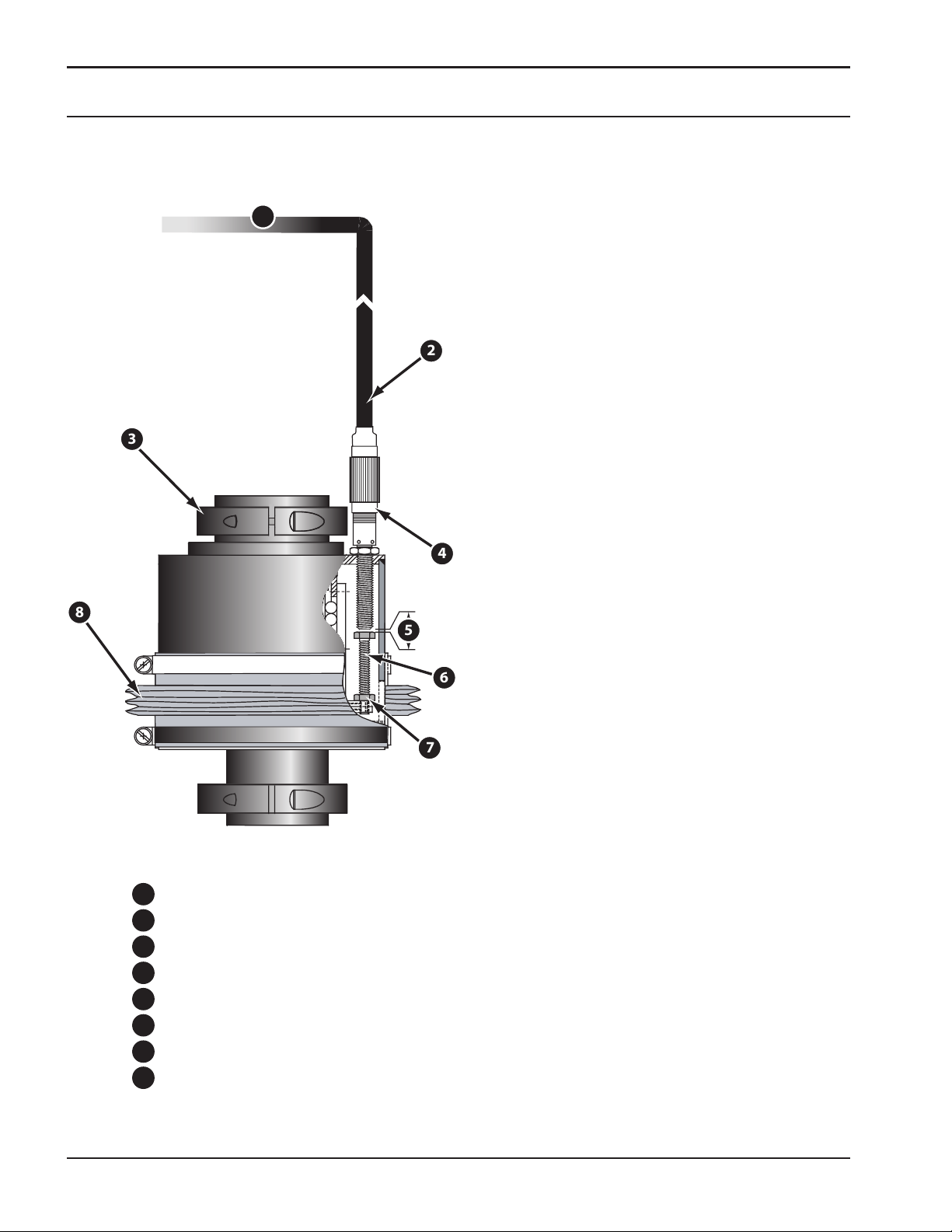
Omni Crash Protection
Description
The Soft Touch Omni® unit is a patented crash
protection and plate sensing device�
To electrical enclosure
Sensor Cable
Proximity Sensor Body
Torch Handle Clamp (2)
Sensitivity gap
Sensor Contact Stud
Lock Nut
Bellows
26
Page 29

B4-200 Plasma Lift Assembly
1
2
3
Function Description
Horizontal movement occurs when the torch runs
into the side of the cutting table� The horizontal
movement is transferred vertically through a unique
patented design using precision bearings� During
this vertical movement, the gap (1) between sensor
(2) and contact stud (3) widens causing a voltage
drop� This 15v drop allows the CNC to recognize an
operation fault� If the torch experiences a vertical
force such as a part ipping or torch driving into
plate, this gap will again widen and voltage drop
will occur, stopping all movement�
27
Page 30

B4-200 Plasma Lift Assembly
Replacing / Adjusting the Omni®
Sensor
Procedure:
1�
Disconnect the cable from sensor by
unscrewing connector�
Loosen lock nut�2�
Unscrew sensor and remove�3�
28
Page 31

B4-200 Plasma Lift Assembly
1
1
NOTICE
Omni® Sensor Installation
See your machine schematic set for cable
wiring instructions for this equipment.
Thread provided jam nut on new sensor�1�
Thread sensor into brass insert hole until sensor 2�
touches contact stud (1)�
NOTICE
Sensor may bottom out on threads before
sensor touches contact stud. Lift torch
assembly and try to turn the sensor down
more to conrm sensor is touching. Adjust
stud up if sensor threads are bottoming out
and repeat procedure.
Make a reference mark on brass threaded insert 3�
in line with a mark on jam nut�
4�
From the position of contact between stud and
sensor, rotate sensor barrel out one full turn�
One full turn results in a gap of 1mm�
29
Page 32

B4-200 Plasma Lift Assembly
lesser
Sensitivity
GREATER
Sensitivity
Possibility of equipment
damage when crashed
Possibility of production interuption
due to incidental crash detection
Least sensitive - no gap
Most sensitive -
1.5 mm gap
No Protection Gap greater than 1.5 mm
Effectiveness of OMNI
Proximity Gap Size
NOTICE
The sensitivity range of the
proximity sensor is 1.5 mm.
By turning sensor back out one full turn
from maximum downward position, crash
sensitivity will be approximately 0.5 mm.
Crash sensitivity can be adjusted ± from
this point by a ¼ turn. A larger gap will
result in a more crash sensitive device.
CAUTION
30
Incidental crash detection may
result in having the gap between
proximity sensor and contact stud
too great.
If gap is larger than working range of
sensor, protection will not be available.
Conversely, inadequate torch protection
may result if gap is set too small. Using
a gap that is as large as operationally
convenient is recommended (no incidental
crashes).
Page 33

B4-200 Plasma Lift Assembly
CAUTION
Sensor cable damage may result
from twisting.
Disconnect cable before rotating Omni®
proximity sensors.
Tighten jam nut�5�
Reattach cable to sensor�6�
31
Page 34

B4-200 Plasma Lift Assembly
Omni® Mechanical Alignment
The Soft Touch Omni® Protection Device requires
precise mechanical alignment to function properly�
Poor mechanical alignment causes false crashes,
hard touches and torch/holder damage� Check
mechanical alignment monthly and lubricate at that
time�
To check for proper alignment:
Move plasma station to a serviceable location,
1�
preferably not over cutting table�
2�
Turn o all machine power and all plasma
auxiliary equipment power�
Electric Shock Kills!
DANGER
Always turn power o on the plasma
console before doing maintenance on a
plasma torch!
Remove both torch clamps and lift torch from 3�
holder�
4�
Grasp torch body and twist from side to side�
If there is any visible twisting movement in the
torch, the Omni will need adjustment�
5�
Hold torch body while trying to move torch
laterally in all directions� If there is any visible
lateral play in torch holder, it will require
adjustment�
32
The Omni device may also need realignment if a
crash signal cannot be cleared or the torch has
horizontal play in the torch holder�
Page 35

B4-200 Plasma Lift Assembly
3
1
5
4
1
2
1
2
3
4
5
152
3
1
4
Disassembly
Remove (2) screws holding upper torch clamp 1�
to torch and remove� Repeat for bottom clamp�
2�
Remove front end of plasma torch
consumables; torch body/bundle can now be
pulled up through torch holder�
3�
Remove (3) screws fastening Omni to support
bracket; these are on the underside of support
bracket�
Torch clamps
Bellows clamps
Bellows
Torch
Proximity Cable
Remove (3) screws holding the cover on Omni 4�
Omni Cover - Top
device and lift cover o�
5�
Loosen (2) clamps holding baes and lift boot
out of way�
33
Page 36

B4-200 Plasma Lift Assembly
1
2
2
1
Lubrication
While unit is disassembled, inspect and lubricate
roller bearings�
1�
Remove one of three bearing retainer plates�
Do not lose any roller bearings – they can fall
out of raceway when retainer plate is removed�
2�
Clean bearings (if necessary) and lubricate well
with silicone grease�
3�
Reassemble bearing retainer plate and move to
next set of bearings�
Lubricate roller bearings
Bearing retainer plates
34
Page 37

B4-200 Plasma Lift Assembly
Initial
Height
Piercing
Height
Cutting
Height
Pilot
Arc
Arc
Starts
Arc Voltage
Height Control
Turns On
Travel
Starts
Encoder Height
HF
Delay
Pierce
Delay
AHC
Delay
Travel
Delay
Technical Descriptions and
Encoder Height Control
Troubleshooting
Introduction
This method for controlling initial height allows
faster cycle times when cutting multiple parts with
a single torch by eliminating unnecessary vertical
movement� Plate thickness is input (�SDP/�TDF le)
and is used to calculate precise slow down positions
from total available stroke (distance of torch tip in
upper travel position to table slat surface)� These
constants dene operation of lift for encoder height
control, software slow down functions and plate
thickness input�
35
Page 38

B4-200 Plasma Lift Assembly
Table Slat
Measured Distance from
Torch Tip to Table Slat
Encoder Station Constant (STA.kon)
Reference Chart
Constant Number Channel Number Description
43
44
94 Distance: ULS <--> Table Slat (Low 16 Bit)
95 Distance: ULS <--> Table Slat (High 16 Bit)
98
99
100
101
*
*
*
*
*
*
*NOTE = these values will be set at factory.
Encoder Pulses / meter (Low 16 Bit)
Encoder Pulses / meter (High 16 Bit)
Distance: Ref Sensor #1 <--> #2 (Low 16 Bit)
Distance: Ref Sensor #1 <--> #2 (High 16 Bit)
Distance: Ref Sensor #1 <--> Nozzle (Low 16 Bit)
Distance: Ref Sensor #1 <--> Nozzle (High 16 Bit)
Setting Station Constants using
distance calculations
Due to varying table heights, plate thickness, and
lift mounting, the end user will often times need
to recongure station constants� In cases where
measurements must be taken and aect constant
values, use the following method for computation�
Example: Distance between upper limit switch and
table slat (STA�kon 94 & 95)�
Measure distance from torch tip when plasma lift is
in upper most travel position to table slat surface�
Subtract 1 inch to allow for any possible table out of
level condition� 9 inches will be used in an example
for this calculation�
9” – 1” (safety clearance) =
1� 8”
2�
Convert inches to micrometers =
8” x 25�4 x 1000 = 203200
3� 319C0
Convert value into hexadecimal =
36
4� word) values =
Split into two 16 bit (or
0003 & 19C0
5�
Convert these two values back into decimal
0003 = 3 19C0 = 6592
6� 3 & STA�kon 94 = 6592
STA�kon 95 =
Page 39

B4-200 Plasma Lift Assembly
Standoff
Scrap
Part
Lower
Voltage
Lower
Standoff
=
Higher
Voltage
Higher
Standoff
=
Initial
Height
Piercing
Height
Cutting
Height
Pilot
Arc
Arc
Starts
Arc Voltage
Height Control
Turns On
Travel
Starts
Encoder Height
HF
Delay
Pierce
Delay
AHC
Delay
Travel
Delay
AVHC Introduction and Oset
Adjustment
The Arc Voltage Height Control system (AVHC)
maintains plasma torch height above work piece
during cutting�
The AVHC system maintains torch height (“stando”)
by measuring arc voltage, comparing this measured
voltage to the reference voltage in the selected
�SDP / �TDF le, then adjusting torch up or down to
maintain that voltage� A longer arc means higher arc
voltage; higher arc voltage results in higher stando;
and vise versa�
This reference value is predetermined in the �SDP /
�TDF le, based on several other cutting parameters,
such as amperage, nozzle orice size, and cutting
speed� Operators can also change desired arc
voltage in parameter window by adjusting Main Arc
Voltage parameter� However, it is good practice to
rename this modied �SDP / �TDF le - this way the
original le is still available for use�
NOTICE
The .SDP / .TDF plasma parameters Ignition
Height, Pierce Height, and Cutting Height
are distances controlled by Encoder Height
Control. AVHC is not utilized until AFTER
cutting cycle begins.
37
Page 40

B4-200 Plasma Lift Assembly
Basic B4 Lift Assembly
Troubleshooting
With proper preventative maintenance performed
on the B4 lift assembly, it will provide many years
of precision and reliable service� However, issues
may arise over time, even with most proactive PM
schedules� Information is provided below to correct
some common assembly failure modes that may
occur and return it to normal operation:
Plasma station attempts to fire in mid-air:
Remove shield cup from PT-36 torch and check for
debris adhering to inside surface; it is likely that torch
is receiving a false touch signal (shield cup to nozzle)�
Vision 50P CNC will deliver an on-screen warning
message in this event�
NOTICE
If carriage position is past either
slowdown soft limit, no on-screen warning
message will be displayed on Vision CNC.
Overload fault indicator on Yaskawa
servopack™ will not clear:
Seen after the station has been "slammed" into
either lower or upper hard limit; rst attempt to
reset power to plasma station by disconnecting
input power cable and reconnect after 10 seconds�
If fault persists, physically remove motor from slide
assembly and shaft will release�
38
Page 41

B4-200 Plasma Lift Assembly
1
2
3
1
2
3
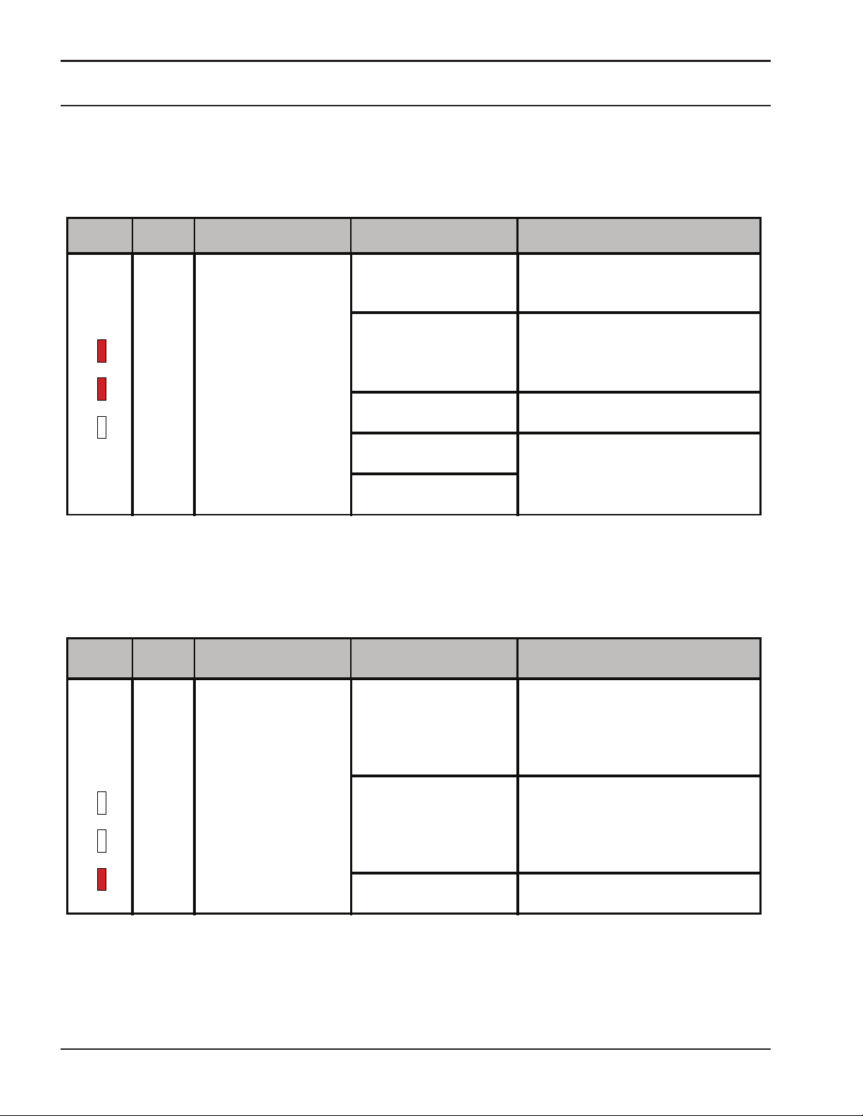
Yaskawa JUNMA Servopack™
Yaskawa Junma Servopack™
Alarm Indicators
The Yaskawa Junma Servopack unit is responsible
for motor speed, direction, and acceleration as
well as encoder count and pulse monitoring� It
also communicates directly with the Vision CNC,
forming a closed-loop monitoring system� Tables on
following pages will describe the servopack’s alarm
displays, their cause and meaning, and generalized
information for corrective action:
Alarm Indicator 1
Alarm Indicator 2
Alarm Indicator 3
39
Page 42

Alarm
Display
Alarm
Name
Condition
Trigger Cause
Corrective
Action
Speed Error
Power was turned ON. A servopack fault occurred. Replace the servopack.
AL1 = On
AL2 = O
AL3 = O
Servo was turned ON.
Phases U, V, and W in
servomotor are wired to
wrong terminals.
Correct wiring.
Encoder wiring is incorrect.
Malfunction occurred due
to noise in encoder wiring.
Take measures against noise for encoder
wiring.
A servopack fault occurred. Replace the servopack.
Phases U, V, and W in
servomotor are wired to
wrong terminals.
Correct wiring.
Servomotor operation
was started or was
switched to high speed
operation.
Encoder wiring is incorrect.
Malfunction occurred due
to noise in encoder wiring.
Take measures against noise for encoder
wiring.
Position pulse reference
input has exceeded 10,000
pulses per revolution.
Correct reference value input.
A servopack fault occurred. Replace the servopack.
Table 1 - Speed Errors
B4-200 Plasma Lift Assembly
40
Page 43

B4-200 Plasma Lift Assembly
Alarm
Display
Alarm
Name
Condition
Trigger Cause
Corrective
Action
AL1 = O
AL2 = On
AL3 = O
Overload
Power was turned on. A servopack fault occurred. Replace the servopack.
Servo was turned ON or
servomotor did not
operate for a reference
input from the controller.
Servomotor main circuit
cable wiring is incorrect or
its contact wiring is faulty.
Check and correct servomotor wiring.
Encoder cable wiring is
incorrect or its contact
wiring is faulty.
A servopack fault occurred. Replace the servopack.
Normal operation
Drop in power supply
voltage.
Ensure power supply voltage is within
permissible range.
Servomotor coil burned
out.
Measure coil resistance. If open, replace
servomotor.
Servomotor was operated
with holding brake
engaged.
Measure voltage of brake terminals and
release brake.
Ambient temperature
around servomotor
exceeded 131°F
(55 °C ).
Take measures to ensure working area is
less than 131°F (55 °C ).
A servopack fault occurred. Replace the servopack.
Table 2 - Overload Errors
41
Page 44
B4-200 Plasma Lift Assembly
Alarm
Display
Alarm
Name
Condition
Trigger Cause
Corrective
Action
AL1 = On
AL2 = On
AL3 = O
Encoder
Error
Power was turned on or
during servomotor
operation.
Encoder wiring and contact
wiring are incorrect.
Correct wiring.
Noise intererence occurred
because encoder cable
distance is too long
Ensure encoder is no more than 20
meters.
Disconnected encoder
cable.
Replace encoder cable through ESAB
Customer Service.
A zero point error occurred. Replace the servopack.
An encoder fault occurred.
Alarm
Display
Alarm
Name
Condition
Trigger Cause
Corrective
Action
AL1 = O
AL2 = O
AL3 = On
Voltage
Error
Power was turned on or
normal operation.
Main power was turned ON
again before the power
supply to servopack was
completely OFF.
Wait until servopack's REF indicator is
OFF, and turn on main power again.
AC power supply voltage
exceeded permissible
range.
Ensure AC power voltage is within
specied range.
A servopack fault occurred. Replace the servopack.
Table 3 - Encoder Errors
Table 4 - Voltage Errors
42
Page 45

B4-200 Plasma Lift Assembly
Alarm
Display
Alarm
Name
Condition
Trigger Cause
Corrective
Action
AL1 = O
AL2 = On
AL3 = On
Built-in
Fan
Stopped
Power was turned on or
during motor operation.
Fan motor stopped. Replace cooling fan in Servopack.
Air intake is blocked. Inspect and clear obstruction.
Alarm
Display
Alarm
Name
Condition
Trigger Cause
Corrective
Action
ALL On
System
Error
Power was turned on. A servopack fault occurred.
Replace the servopack and contact ESAB
customer support.
Alarm
Display
Alarm
Name
Condition
Trigger Cause
Corrective
Action
All ash
on to o
at regular
intervals
Reference
changed
Power was turned on or
during servomotor
operation.
N/A
Turn on main power again (operation of
the servomotorcan continue during
display of this alarm).
43
Page 46

B4-200 Plasma Lift Assembly
44
Page 47

B4-200 Plasma Lift Assembly
REPLACEMENT
PARTS
REPLACEMENT
PARTS
45
Page 48

B4-200 Plasma Lift Assembly
46
Page 49

Replacement Parts
Table of Contents
Introduction
General Information ��������������������������������������������������������������������������������������������������������������������������������������������������������������������������� 3
Ordering Information ������������������������������������������������������������������������������������������������������������������������������������������������������������������������ 4
B4-200 OEM Lift Kit
0560947166 Rev 01 ����������������������������������������������������������������������������������������������������������������������������������������������������������������������������� 5
B4 Lift Assembly
0560943522 Rev 04 ����������������������������������������������������������������������������������������������������������������������������������������������������������������������������� 9
B4 Lift Electronics Enclosure
0560944477 Rev 06 �������������������������������������������������������������������������������������������������������������������������������������������������������������������������� 15
Wire Kit, Soft Touch
0560947295 Rev 02 ��������������������������������������������������������������������������������������������������������������������������������������������������������������������������� 19
Omni Soft Touch Assy
0560941537 Rev 00 ���������������������������������������������������������������������������������������������������������������������������������������������������������������������������21
Consumable and Spare Part Reference List
Part Numbers Vary ����������������������������������������������������������������������������������������������������������������������������������������������������������������������������23
Replacement Parts
Page 50

Replacement Parts
Replacement Parts
Page 51

Replacement Parts
Introduction
General Information
This section provides replacement parts information
and will assist during station maintenance� It is
arranged by functional groups or assemblies for easy
identication of individual parts and replaceable
assemblies� The Replacement Parts List consists of
a parts list for the main assembly and one for each
major assembly and subassembly� Item numbers
that identify parts in the illustration are given in the
list where applicable, along with part numbers and
descriptive information�
Common hardware items or other parts readily
available from commercial sources are not included�
Parts purchased from vendors by ESAB are listed by
ESAB part numbers� Hardware is specied as items in
the parts list but normally doesn’t have an ESAB part
number�
The end of this manual section has spare parts and
consumable reference sheets� Please use these when
ordering wear items and consumables, based on
your needs�
Replacement Parts
Page 52

NOTICE
Replacement Parts
Ordering Information
When ordering replacement parts, order by part
number and complete part description as given in
the description column� Also, give machine model
number and serial number� Address all inquiries
to your local ESAB Distributor or to ESAB Cutting
Systems, P�O� Box 100545, Florence, South Carolina,
29501�
To avoid unnecessary delays, positively
identify your correct assembly before
ordering replacement parts.
Replacement Parts
Page 53

REPLACEMENT
PARTS
B4-200 OEM Lift Kit
58
425
7
1
22
242111910
23
1920202416
17
3
25
4
8
5
152616
181413
276
0560947166 Rev 01
Replacement Parts
5
Page 54

Replacement Parts
REPLACEMENT
PARTS
#8 (QTY 1).
IS
#11, #29 AND
NOTES
:
1. IF ELECTRICAL SOFT TOUCH IS NOT
REQUIRED, SELECT ITEM
IF ELECTRICAL SOFT TOUCH
REQUIRED, SELECT ITEMS
#30 (QTY 1 EACH).
2. ELECTRICAL SOFT TOUCH CANNOT BE
USED WITH UNDERWATER CUTTING.
3. THIS DRAWING HAS ELECTRICAL SOFT
TOUCH OPTION DISPLAYED.
4. CABLE LENGTHS SELECTED FROM
TABLES #1 AND #2 MUST MATCH
.
TABLE 1 - INPUT POWER CABLE
LENGTH PN
4m (13')
0560947087
5m (16')
0560947088
6m (19')
0560947089
7m (23')
0560947090
8m (26')
0560947091
9m (30')
0560947092
10m (33')
0560947093
15m (49')
0560947094
20m (66')
0560947095
TABLE 2 - ACON CABLE
LENGTH PN
4m (13')
0558008467
5m (16')
0558008468
6m (19')
0558008469
7m (23')
0558008470
8m (26')
0558008471
9m (30')
0558008472
10m (33')
0558008473
15m (49')
0558008478
20m (66')
0558008479
MATCH CABLE LENGTHS
6
Page 55

Replacement Parts
REPLACEMENT
PARTS
ITEM QTY PN DESCRIPTION
1 REF 0558008150 RAS Dual Volt Divider AY
2 REF 0558008252 Plasma Gas Box
3 REF 0558008301 PT-36 m3 CAN (4.5')
4 1 0560936682 BRKT OMNI MOUNTING
5 1 0560941537 ASSY, OMNI SOFT TOUCH M3 PROX
6 1 0560943522 ASSY, B4-200 LIFTER m3
7 1 0560944261 GUIDE RING
8 REF 0560947811 CABLE, CRASH PROTECTION
9 REF 0560945380 Bracket Plasma Station B4
10 REF 0560945381 Nut Plate B4 Plasma Bracket
11 REF 0560947295 ELECTRIC SOFT TOUCH OPTION KIT
12 1 0560947934 TORCH LEAD HOLDER B4
13 1 2081816 PLASMA WARNING LABEL
14 1 2132645 BRACKET, SIGN DANGER PLASMA
15 4 M3.5 x 0.6 Hex Nut
16 7 M8 x 1.25 Hex Nut
17 2 M8 x 1.25 x 25 Hex Bolt
18 1 M8 x 1.25 x 30 Hex Bolt
19 4 M8 x 1.25 x 40 Hex Bolt
20 8 M - 8 N Plain Washer
21 2 M6x1 x 16 Forged Socket Head Cap Screw x Metric
22 4 M8x1.25 x 20 Broached Socket Head Cap Screw - Metric
23 6 M8x1.25 x 30 Forged Socket Head Cap Screw x Metric
24 4 DIN 7980 - 8 Spring Washer
25 3 M4 x 10 Hexagon Socket Head Cap Screw
26 4 M3.5 x 8 - 4.8 - H Cross Recessed Pan Head Machine Screw
27 PICK
SEE TABLE 1
CABLE, INPUT POWER
28 PICK
SEE TABLE 2
CABLE, ACON
29 REF 0560947906 CABLE, INTERCON, LIFT-TOUCH ENCL, 0.5m
30 REF 0560947865 CABLE, SOFT TOUCH PROX, 1.0m, SHLD
PARTS LIST
7
Page 56

REPLACEMENT
PARTS
Spacer Page
Replacement Parts
8
Page 57

Replacement Parts
REPLACEMENT
PARTS
NOTES:
1. FOR PROPER SEATING, TORQUE TAPER LOCK BUSHING (ITEM 14) SCREWS TO 4
FT. LBS. TIGHTEN SEQUENTIALLY AS SHOWN ON SHEET 2.
45
26
1
LINEAR RAILS
GREASE POINTS
6.00
31.11
REF. LIFTER AT
UPPER LIMIT
33
GREASE POINT ACCESS
ACME SCREW NUT
26
1
45
33
B4 Lift Assembly
0560943522 Rev 04
9
Page 58

Replacement Parts
REPLACEMENT
PARTS
8
28
23
72
60
1
2
3
4
ITEM 14
(SEE NOTE 1)
40
72
60
40
18
70
5
71
61
47
237342
48
19
58
10
82825
696467
274650637
48
30
48
5
47
10
Page 59

Replacement Parts
REPLACEMENT
PARTS
SCREW SUB-ASSEMBLY
SLIDE SUB-ASSEMBLY
MOTOR ASSEMBLY
2
6
12
22
9
31
66
24
32
62
41
15
4
34
57
3
59
20
55
65
21
56
43
68
59
67
11
43
6
2
686662
24
9
12
41
32
31
22
59
351543443
3294411345759
67
565520
52
65
21
11
Page 60

Replacement Parts
REPLACEMENT
PARTS
ITEM QTY PN DESCRIPTION
1 1 0003733136 Bellow for A5 and B2-200
2 2 0003775229 Linear Rail 1605-203-31,356
3 1 0006164011 Retaining Ring DIN472 32x1.2
4 1 0006261041 Washer 12x18x1 DIN 988
5 2 0560935261 MICRO SWITCH SR-3-E-SW
6 1 0560938398 SUPPORT LIFTER B2-200
7 2 0560938405 CLIP WIRE DOUBLE
8 1 0560938435 BELT TIMING 5mm PITCH 16mm FACE
9 4 0560938452 Fitting, Compression, M6-1 X 4mm OD
10 1 0560939021 CAM LIMIT SWITCH B2-200
11 1 0560939434 SCREW 200MM B LIFT
12 2 0560939898 FITTING GREASE 45 DEGREE
13 1 0560941403 PULLEY TIMING22.5MM BORE
14 1 0560941404 KEYLESS LOCKING ASSEMBLY 12MM X 18MM
15 1 0560943526 Jumna Motor Mounting Bracket B4
16 1 0560943527 PULLEY TIMING 5mm PITCH 16mm FACE 16T
17 1 0560943528 B4 Tensioning Plate
18 2 0560944119 Mount, Cable Tie Holder, M4
19 1 0560944206 HOLDER FOR SWITCH
20 1 0560944262 Junma Motor 200W
21 1 0560944265 JUNMA MOTOR BUSHING
22 1 0560944358 PLATE, BACK, B4-200 LIFT
23 1 0560944360 COVER, BOTTOM, B4 LIFT
24 1 0560944390 MANIFOLD, GREASE FITTING
25 1 0560944392 STATION BOX ADAPTER PLATE
26 1 0560944394 ASSY, COVER B4-200 LIFT
27 1 0560944476 SHIELD, B4 LIFTER
28 1 0560944477 ASSY, STA. CTRL. BOX B-4 LIFT
29 1 0560945353 SCREW NUT B4 LIFTER
30 1 0560945354 BRACKET LIMIT SWITCH B4-200 UPPER
31 1 0560945355 Grease Line Right B4-200
32 1 0560945356 Grease Line Left B4-200
33 1 0560945358 Hole Plug Flush 7/8"
34 1 0560945364 Spring Lower B4
35 1 0560945418 BUSHING SCREW B4-200
36 1 0560945419 SPACER, B4-200 LIFT
37 REF 0560947285 Basic Spares B4-200 Lift
38 REF 0560947286 Extended Spares B4-200 Lift
39 1 0560947910 Plug, Snap in, 1.5"
40 2 0560948330 CLAMP CBL 5/8"
41 2 2238778 BLOCK RUNNER SLIMLINE SZ 25 LONG
42 2 --- LINEAR RAIL PLASTIC
43 2 407058 Deep Groove Ball Bearing
44 1 56997241 FITTING GREASE 6MM
45 1 954075 NAMEPLATE 2.30 X 3.38
PARTS LIST
12
Page 61

Replacement Parts
REPLACEMENT
PARTS
ITEM QTY PN DESCRIPTION
46 4 M8 x 1.25 Hex Nut
47 4 M3 x 0.5 x 16 Broached Hexagon Socket Button Head Cap Screw - Metric
48 10 M4 x 0.7 x 10 Broached Hexagon Socket Button Head Cap Screw - Metric
49 8 M4 x 0.7 x 6 Broached Hexagon Socket Button Head Cap Screw - Metric
50 4 M6 x 1 x 12 Broached Hexagon Socket Button Head Cap Screw - Metric
51 1 M3x0.5 x 2 Broached Hexagon Socket Set Screw - Flat Point
52 1 M5 x 20 Hexagon socket screws
53 1 D0560946668 B4 M3 Station Wiring Build
54 1 D0560946668 B4 M3 STATION WIRING BUILD
55 4 DIN 126 - 6.6 Washers for hexagon bolts
56 4 DIN 128 - A5 Spring Washer
57 1 DIN 9021 - 6.4 Washer
58 2 M4 x 16 Cylinder Head Cap Screw
59 9 M6 x 12 Cylinder Head Cap Screw
60 4 M6 x 16 Cylinder Head Cap Screw
61 2 DIN 934 - M3 Hex Nut
62 2 IS 3063 - 4 LOCK WASHER
63 4 IS 3063 - 6 LOCK WASHER
64 4 IS 3063 - 8 LOCK WASHER
65 1 ISO 4035 - M5 Hex Jam Nut
66 2 M4 x 30 Hexagon Socket Head Cap Screw
67 10 M5 x 12 Hexagon Socket Head Cap Screw
68 12 M6 x 20 Hexagon Socket Head Cap Screw
69 4 M8 x 20 Hexagon Socket Head Cap Screw
70 2 M4 x 10 - 4.8 - H Countersunk at head screws
71 2 STD-000149 Spring Washer DIN 128 - A3
72 2 SocHeadCapScrew-MET M6-1.0 x 80 SHCS
73 4 M4 x 16 Hexagon Socket Head Cap Screw
PARTS LIST
BOLT SIZE TORQUE (N-m) TORQUE (Ft-lb)
M3 0.9 0.7
M4 2.6 1.9
M5 5.0 3.7
M6 8.7 6.4
M8 21.1 15.6
M10 42.0 31.0
M12 73.2 54
RECOMMENDED BOLT TORQUE VALUES
13
Page 62

REPLACEMENT
PARTS
Spacer Page
Replacement Parts
14
Page 63

Replacement Parts
REPLACEMENT
PARTS
11327
292726
7
12
6
1
4
8
17
203221
16
5
32
31
7
113618
5
15
2
23
3
32
25
7
11
24
3
35
B4 Lift Electronics Enclosure
0560944477 Rev 06
15
Page 64

Replacement Parts
REPLACEMENT
PARTS
33
13
30
14
16
Page 65

REPLACEMENT
PARTS
Replacement Parts
PARTS LIST
ITEM QTY GIN DESCRIPTION
1 1 0004654140 END PLATE
2 1 0006100009 HEX. SCREW-ISO4017-M4X16-
3 4 0006100015 HEX. SCREW-ISO4017-M5X10-
4 2 0006101008 HEX.S.H.C.SCR.-ISO4762-M4X10
5 2 0006101318 CHEESE HEAD SCREW M5 X 10
6 4 0006118111 ISO7380-M6X10-A2 HEXAGON SOCK. BUTTON HEAD SCREW
7 8 0006130035 HEX.NUT-S1-ISO4032-M4-
8 2 0006150003 WASHER GALVANIZED A4
9 4 0006150004 WASHER GALVANIZED A5
10 4 0006150005 WASHER GALVANIZED B6
11 6 0006157017 SPR.L.WASHER-DIN128-B4
12 1 0006159018 TOOTH LOCKED WASHER DIN6797-V4,3-
13 1 0558954035 LABEL CE LOGO
14 1 0560936470 WARNING HAZARD VOLTAGE INSIDE
15 1 0560941432 BUS BAR, COPPER
16 1 0558040029 MCU PROG’D (G2/IGC) OEM B4 LIFT
17 1 0560944331 SERVOPACK
18 1 0560944343 DIN RAIL MOUNTING 35MM X 7.5MM
19 1 0560945363 JUNMA ENCODER SPLICE CABLE
20 1 0560945374 CNA CONNECTOR
21 1 0560945375 CNA CONNECTOR
22 1 0560945582 FACE PANEL ASSEMBLY, M3, B4
23 1 0560945584 ASSY, STATION CONTROL BOX
24 1 0560945881 TRANSFORMER, 12/24 VSEC 80 VA
25 1 0560947161 FILTER, EMI, 250VAC 5A
26 1 0560948408 CONTACT INSERT 12 PIN
27 1 0560948410 PLASTIC SLEEVE HOUSING
28 1 0560948411 HALF SCREW CONNECTION (7-14MM)
29 1 0560948412 HALF SCREW CONNECTION(4-6.5MM)
30 1 0560950378 NAMEPLATE 2.38 X 3.38
31 4 0560950488 GROUND CLIP
32 4 0560950489 RING TERMINAL LUG
33 1 0560950490 GROUND DECAL
34 A/R 0560950491 WIRE 16AWG GRN/YEL
35 8 0560950492 TERM FAST .25 F/90 18-22 AWG
36 9 0560950498 TERMINAL INLINE FEMALE 0.25” X 14-16AWG
37 1 0560951219 B4 M3 STATION BOX SCHEMATIC
17
Page 66

REPLACEMENT
PARTS
Spacer Page
Replacement Parts
18
Page 67

REPLACEMENT
PARTS
Wire Kit, Soft Touch
213
567
4
ITEM QTY PN DESCRIPTION
1 1 0560946810 ASSY, SOFT TOUCH BOX
2 1 0560947291 SOFT TOUCH BRACKET
3 1 0560947293 WIRE KIT, SOFT TOUCH
4 8 DIN 125 - A 6.4 Flat Washer
5 4 M5x0.8 x 16 SHCS - Metric
6 4 DIN 127 - A 5 Spring Washer
7 4 M - M5 x 0.8 Hex Nut
PARTS LIST
0560947295 Rev 02
Replacement Parts
19
Page 68

REPLACEMENT
PARTS
Spacer Page
Replacement Parts
20
Page 69

REPLACEMENT
PARTS
B
B
SECTION B B
A
A
SECTION
AA
11
25223332123314
8
9
5
10
6
7
2
14
13
34
17
25
22
18
153119
14
262221
35
23
31
12
Omni Soft Touch Assy
0560941537 Rev 00
Replacement Parts
21
Page 70

Replacement Parts
REPLACEMENT
PARTS
ITEM
NO.
PART NO. QTY. DESCRIPTION
QUANTITIES ARE IN U/M ESTIMATED BY INVENTORY
BILL OF MATERIALS
1 2238468 1 SLEEVE, TORCH HOLDER
2 2233370 2 CLAMP, TORCH
3 2238469 1 RING, TORCH MOUNTING
4 0560936077 1 COVER OMNI SOFT TOUCH W/PROX
5 2157761 3 SLEEVE, SPRING
6 2238471 1 BEARING HOUSING
7 2238478 1 BRACKET, TOP CLAMP
8 2209090 3 SPRING, COMPRESSION DIE
10 05N00080 3 NUT, HEX ~ M5-0.8
9 2233364 3 STUD, (METRIC)
12 05S24010 4 SCREW, SET,CONE PT. HEX SOC. ~ M5-0.8 X 10 MM LG.
11 - - REF LOCK NUT M8-1.0
13 04S12012 3 SCREW, HEX SOC HD. CAP ~ M4-0.7 X 12 MM LG.
14 0560935243 1 PROX M8 4W PNP QD
15 2238484 1 BLOCK
16
17 57000462 12 PIN, DOWEL ~ .250 DIA X .50 LG
18 23211302 2 SCREW, HEX SOC HD. CAP ~ M3-0.5 X 16 MM LG.
19 - - 1 SCREW,HEX HD. CAP ~ M5-0.8 X 45 MM LG.
20
21 2238473 2 PLATE, BEARING ADJUSTMENT
22 03S12006 7 SCREW, HEX SOC HD. CAP ~ M3-0.5 X 6 MM LG
23 2238472 2 RETAINER, BEARING PLATE
24
25 2238485 1 RETAINER, NON-ADJUSTMENT
26 06S26020 4 SCREW, HEX SOC HD. CAP S.S. ~ M6-1.0 X 20 MM LG.
28 03S12012 2 SCREW, HEX SOC HD. CAP ~ M3-0.5 X 12 MM LG.
29
30
31 05N01080 8 NUT, HEX JAM ~ M5-0.8
32 2231375 2 CLAMP, WORM 5" DIA.
33 2238860 1 BOOT
34 77500101 A/R GREASE, SILICONE
35 03S12008 12 SCREW, HEX SOC HD. CAP ~ M3-0.5 X 8 MM LG
27
22
Page 71

Replacement Parts
REPLACEMENT
PARTS
BASIC SPARE PARTS, B4-200 LIFT
ESAB PN 0560947285 REV 00
ITEM QTY PN DESCRIPTION
1 1 0003733136 BELLOWS
2 1 0560935261 MICROSWITCH SR-3-E-SW
3 1 0560938435 TIMING BELT
4 1 0560939434 ACME SCREW
5 1 0560941403 TIMING PULLEY
6 1 0560943527 TIMING PULLEY
7 1 0560945353 ACME SCREW NUT
8 2 2238778 RUNNER BLOCK
9 2 407058 BALL BEARING
PARTS LIST
Consumable and Spare Part
Reference List
Part Numbers Vary
NOTICE
1-800-ESAB-123
The following section was designed to assist
operators in identifying and ordering maintenance/
consumable parts� Items listed below are parts that
will need replacement at least on a yearly basis,
many with smaller maintenance intervals� Quantities
suggested are estimated, based on normal machine
usage, product lead times and availability; end users
will need to best decide what quantities to purchase
based on their production schedule�
The parts represented here, at some point,
will be necessary to maintain the process
tool. Please dial our toll free number for
pricing and availability or contact your
nearest distributor.
23
Page 72

REPLACEMENT
PARTS
BASIC SPARE PARTS, B4-200 LIFT
ESAB PN 0560947285 REV 00
EXTENDED SPARE PARTS, B4-200 LIFT
ESAB PN 0560947286 REV 01
ITEM QTY PN DESCRIPTION
1 1 0003733136 BELLOWS
2 1 0560935261 MICROSWITCH SR-3-E-SW
3 1 0560938435 TIMING BELT
4 1 0560939434 ACME SCREW
5 1 0560941403 TIMING PULLEY
6 1 0560943527 TIMING PULLEY
7 1 0560945353 ACME SCREW NUT
8 2 2238778 RUNNER BLOCK
9 2 407058 BALL BEARING
PARTS LIST
ITEM QTY PN DESCRIPTION
1 1 0003733136 BELLOWS
2 2 0003775229 LINEAR RAIL
3 1 0560935261 MICROSWITCH SR-3-E-SW
4 1 0560938435 TIMING BELT
5 1 0560939434 ACME SCREW
6 1 0560941403 TIMING PULLEY
7 1 0560943527 TIMING PULLEY
8 1 0560944262 JUNMA MOTOR
9 1 0560945353 ACME SCREW NUT
10 1 0560945364 SPRING
11 2 2238778 RUNNER BLOCK
12 2 407058 BALL BEARING
13 1 0006164011 RETAINGING RING
14 1 0560941404 KEYLESS BUSHING
15 1 0560944331 JUNMA SERVOPACK
PARTS LIST
Replacement Parts
24
Page 73

Page 74

Revision History:
02 - Added technical specications on Page 8, updated mounting plate dimensions on Page 9 and updated
•
replacement parts.
•
03 - Updated mounting dimensions.
04 - Removed MCU from extended spares list. •
Page 75

®
Customer // Technical Support
(843) 664-4405
(800) ESAB-123 (372-2123)
ESAB Welding and Cutting Products
PO BOX 100545 Ebenezer Road
Florence, SC 29501-0545
http://www.esab.com
ESAB Cutting Systems – Canada
6010 Tomken Road
Mississauga, Ontario Canada L5T 1X9
Phone: (905) 670-0220
Fax: (905) 670-4879
ESAB Cutting Systems GMBH
Robert-Bosch-Strasse 20
Postfach 1128
D-61184 Karben 1
Phone 011-49-6039-400
Fax 011-49-6039-403-02
http://www.esab.de
 Loading...