


LUA 400
Instruction manual Инструкция по эксплуатации
Valid from serial no. 535--xxx--xxxx0456 053 027 020311

Русский 3...............................................
ENGLISH 12..............................................
Rights reserved to alter specifications without notice.
Оставляемза собой право изменять спецификацию безпредупреждения.
-- 2 --

Русский
1 ТЕХНИКА БЕЗОПАСНОС ТИ 4........................................
2 ВВЕДЕНИЕ 4.......................................................
2.1 Области применения. 5....................................................
2.2 Ручная дуговая сварка (ММА). 5............................................
2.3 Полуавтоматическая сварка в защитных газах ( MIG/MAG). 5.................
2.4 Аргоно-дуговая сварка неплавящимся электродом ( TIG ). 5.................
3 Техническое описание 6............................................
3.1 Система управления 6.....................................................
3.2 ТЕХНИЧЕСКИЕ ДАННЫЕ 7.................................................
4 ПОДГОТОВКА К РАБОТЕ 8..........................................
Регулирующие устройства на передней панели LUA: 8.............................
Регулирующие устройства на задней панели LUA: 8...............................
5 РАБОТА УС ТАНОВКИ 9..............................................
Устройства безопасной работы 9.................................................
6 ТЕХНИЧЕСКОЕ ОБСЛУЖИВАНИЕ 10.................................
ЗАКАЗ ЗАПАСНЫХ ЧАСТЕЙ 10.....................................................
7 ПРИНАДЛЕЖНОСТИ 10..............................................
LUA 400 в мультивольтажном исполнении. 10.......................................
Пульты дистанционного управления (ДУ) 10........................................
Подключения и удлинители кабеля 11..............................................
Дополнительные принадлежности LUA: 11.........................................
СХЕМА 21..............................................................
СПИСОК ЗАПАСНЫХ ЧАСТЕЙ 22........................................
TOCr
-- 3 --

1 ТЕХНИКА БЕЗОПАСНОСТИ
ПРЕДУПРЕЖДЕНИЕ !
ДУГОВАЯ СВАРКА И РЕЗКА МОГУТ ПРИЧИНИТЬ ВРЕД ВАМ И ОКРУЖАЮЩИМ. ПРИМИТЕ
НЕОБХОДИМЫЕ МЕРЫ БЕЗОПАСНОСТИ ПРИ ПРОВЕДЕНИИ СВАРОЧНЫХ РАБО Т.
ОЗНАКОМЬТЕСЬ С ТЕХНИКОЙ БЕЗОПАСНОСТИ, РАЗРАБОТАННОЙ НА ВАjЕМ ПРЕДПРИЯТИИ.
ПОР АЖЕНИЕ ЭЛЕКТРИЧЕСКИМ ТОКОМ ОПАСНО ДЛЯ ЖИЗНИ !
S Установите и заземлите сварочный аппарат в соответс твии с применяемыми стандартами.
S Не касайтесь оголенных электрических частей или электродов голыми руками, мокрыми перчатками
илимокройодеждой.
S Изолируйте себя от земли и заготовки.
S Обеспечь те безопасность на своем рабочем месте.
ÑÂАРОЧНЫЕ ДЫМЫ И АЭРОЗОЛИ - могут быть опасны для здоровья.
S Старайтесь, чтобы ваша голова находилась вне зоны дыма..
S Используйте вентиляцию и дымоотсос ыдля удаления дымов и аэрозолей из зоны дыхания и
окружающегопространства
ИЗЛУЧЕНИЕ ДУГИ - может нанести вред глазам и коже.
S Защищайте ваши глаза и кожу. Используйте маску с правильно подобранным защитнымстеклом и
спецодежду
S Защищайте окружающих посредством стенок и занавесок.
ПОЖАРООПАСНОСТЬ
S Искры при сварке могут стать причиной пожара.Обеспечьтеотсутствиепожароопасных материалов
в близлежащей зоне.
ШУМ - Повышенный шум может повредить слух
S Защитите свои уши с помощью наушников или берушей.
S Предупредите о риске окружающих.
СБОЙ В Р АБОТЕ - При сбоях в работе обратитесь за помощью к специалисту.
ПРОЧТИТЕ И ПОЙМИТЕ ИНСТРУКЦИЮ ПО ЭКСПЛУАТАЦИИ ПЕРЕД ТЕМ, КАК ПОДКЛЮЧИТЬ
ОБОРУДОВАНИЕ И НАЧАТЬ РАБОТУ
ЗАЩИТИТЕ СЕБЯ И ОКРУЖАЮЩИХ !
ПРЕДУПРЕЖДЕНИЕ !
Это оборудование предназначено для промышленного использования.
При применении в домашних условиях оно может вызвать ра диопомехи.
Ответственность несет пользователь оборудования.
2 ВВЕДЕНИЕ
LUA-400 универсальный cварочный выпрямитель инверторного типа,
предназначенныйдляручнойдуговойсваркиштучнымиэлектродами,
аргоно-дуговой сварки, полуавтоматической сварки в защитных газах и
воздушно-дуговой строжки. Собранный на совершенной элементной базе,
LUA-400 обеспечивает высокую скорость управления параметрами сварки ,
низкую потребляемую мощность прекрасные сварочные характеристики и
компенсацию колебаний сетевого напряжения.
Созданный, как источник инверторного типа, LUA-400 имеет небольшие
размеры и вес. Табличка с указанием схем соединений находится на за дней
стенке источника питания. LUA-400снабжен двумя ручками, соединительными
болтами и кабельными разъ¸мами.
bu07d2r -- 4 --

2.1 Области применения.
LUA-400 идеальный выбор для тех , кому нужен универсальный сварочный
выпрямитель. На базе источника питания LUA-400 можно, используя другие
стандартные компоненты фирмы “ ESAB”, создавать установки для
различных способов сварки (TIG, MMA, MIG/MAG).
Настоящая инструкция содержит описание LUA-400 только, как источника
питания. ( Дополнительные данные для комплектации сварочных установок
можно увидеть в разделе “ Принадлежности “).
2.2 Ручная дуговая сварка (ММА).
Повышенное напряжение холостого хода обеспечивает легкое и плавное
возбуждение дуги и помогает избегать “примерзания” электрода в начале
сварки. Если вс¸-таки это произошло, то величина сварочного тока
авт оматически уменьшится и электрод можно будет без труда отделить от
изделия и немедленно возобновить сварку. Это свойство LUA-400
способствует улучшению качества сварки корневых швов и помогает
сохранять электроды.
2.3 Полуавтоматическая сварка в защитных газах ( MIG/MAG).
При полуавтоматической сварке источник питания LUA-400 должен
дополнительно комплектоваться подающим механизмом, горелкой и газовым
баллоном. Использование последних достижений в области электроники
позволяют создавать первоклассные, компактные и надежные установки
полуавтоматической сварки.
Выбрав то, что необходимо из широкого перечня принадлежностей фирмы
“ESAB”:
подающий механизм, пульт дистанционного управления, балансир , блок
водяного охлаждения и т.д. Вы получаете систему полуавтоматической
сварки , удовлетворяющую Вашим потребностям. Более подробно о
комплектации полуавтоматических систем и выборе принадлежностей cм.
специальную брошюру.
2.4 Аргоно-дуговая сварка неплавящимся электродом ( TIG ).
Скомплектовав LUA-400 дополнительно блоком TIG-AID и горелкой TIG, Вы
получите профессиональную систему аргоно-дуговой сварки неплавящимся
электродом. LUA-400позволяет вести сваркуна минимальных токах от 15А,
что особенно важно при сварке тонколистовых конструкций.
Во время сварки методом TIG функции “мягкого старта” и “антипримерзания”
должны быть выключены. Это достигаетс я установкой переключателя в
положение TIG-сварки.
bu07d2r -- 5 --

3 Техническое описание
Инверторные преобразования происходят следующим образом:
Переменный 3-х фазный ток питающей сети преобразуется в постоянный , а
затем обратно в переменный , но с гораздо более высокими значениями
частоты, после чего сварочный ток снова через выпрямитель преобразуется в
постоянный. Весь цикл преобразований управляется электронной платой, что
обеспечивает требуемыестатические характеристики и динамические
параметры источника питания LUA-400.
LUA-400 состоит из следующих блоков:
S Блок управления расположен наверху и состоит из управляющей
микросхемы и электронных регулирующих устройств.
S Вентиляционный отсек состоит из вентилятора и силового резистора.
SПрочие компоненты, которые условно делятся на сетевые компоненты и
компоненты сварочной цепи.
3.1 Система управления
Управление работой LUA-400 осуществляется современной электроникой, что
да¸т возможность получить прекрасныестатические и динамические
характеристики, а также высокий к.п.д. и коэффициент мощности , низкий
минимальный ток сварки, обеспечивает “ непримерзание” электрода,
возможность использования пульта дистанционного управления, а также
компенсацию колебаний сетевого напряжения и т.д.
bu07d2r -- 6 --

3.2 ТЕХНИЧЕСКИЕ ДАННЫЕ
Диапазон сварочного тока 15 A/20 V - 400 A/36 V
при сварке TIG 15-400 A
при сварке ММА 20-400 A
при сварке MIG/MAG 45-400 A
Допустимая нагрузка
при сварке ММА
ïðè ÏÂ 35% 400 A/36 V
ïðè ÏÂ 60% 315 A/32.6 V
приПВ100% 150A/26V
при сварке TIG
ïðè ÏÂ 35% 400 A/26 V
ïðè ÏÂ 60% 315 A/22.6 V
ïðè ÏÂ 100% 250 A/20 V
при сварке MIG/MAG
ïðè ÏÂ 35% 400 A/34 V
ïðè ÏÂ 60% 315 A/30 V
ïðè ÏÂ 100% 200 A/24 V
Напряжение холостого хода 65-75 V
Мощность холостого хода 0.06 kW
Коэффициент мощности l 0.94
Ê.Ï.Ä. h 0.80
Класс защиты IP 23
Класс применения
Âåñ 48 kg
Характеристика питающей сети
Напряжение (В)
3x230 3x400 3x415 3x440 3x500 3x550
Частота (Hz) 50/60 50/60 50 60 50 60
Ток первичной цепи (A) 40 26 25 18 19 15
Предохранитель (A) 35 20 20 20 20 20
Сечение кабеля (мм2) 4x6 4x2.5 4x2.5 4x2.5 4x2.5 4x2.5
Данный выпрямитель удовлетворяет требованиям стандарта IEC 974-1
Сечения кабелей - согласно шведских стандартов.
Символ означает что установка пригодна к применению в условиях с
повышенной электроопасностью.
Оборудование с маркировкой IP 23 предназначено д ля наружных и
внутренних работ.
bu07d2r -- 7 --
4 ПОДГОТОВКА К РАБОТЕ
Убедитесь в том, что выпрямитель подсоединен к питающей сети
соответствующего напряжения. Номинальное напряжение питания
тр¸хфазовой сети указано на табличке, прикрепл¸нной к задней стенке
установки.
Выпрямитель LUA поставляетс я в комплекте с сетевым кабелем. Кабель
соединен с выводами L1, L2 и L3 на терминальном блоке K11. Величина
фазовой частоты не имеет значения. Подвод кабеля находится в правом
нижнем углу задней стенки выпрямителя. Заземление осуществляется
согласно действующим нормам.
Рекомендуемое сечение сварочного и возвратного кабелей 50 мм2.
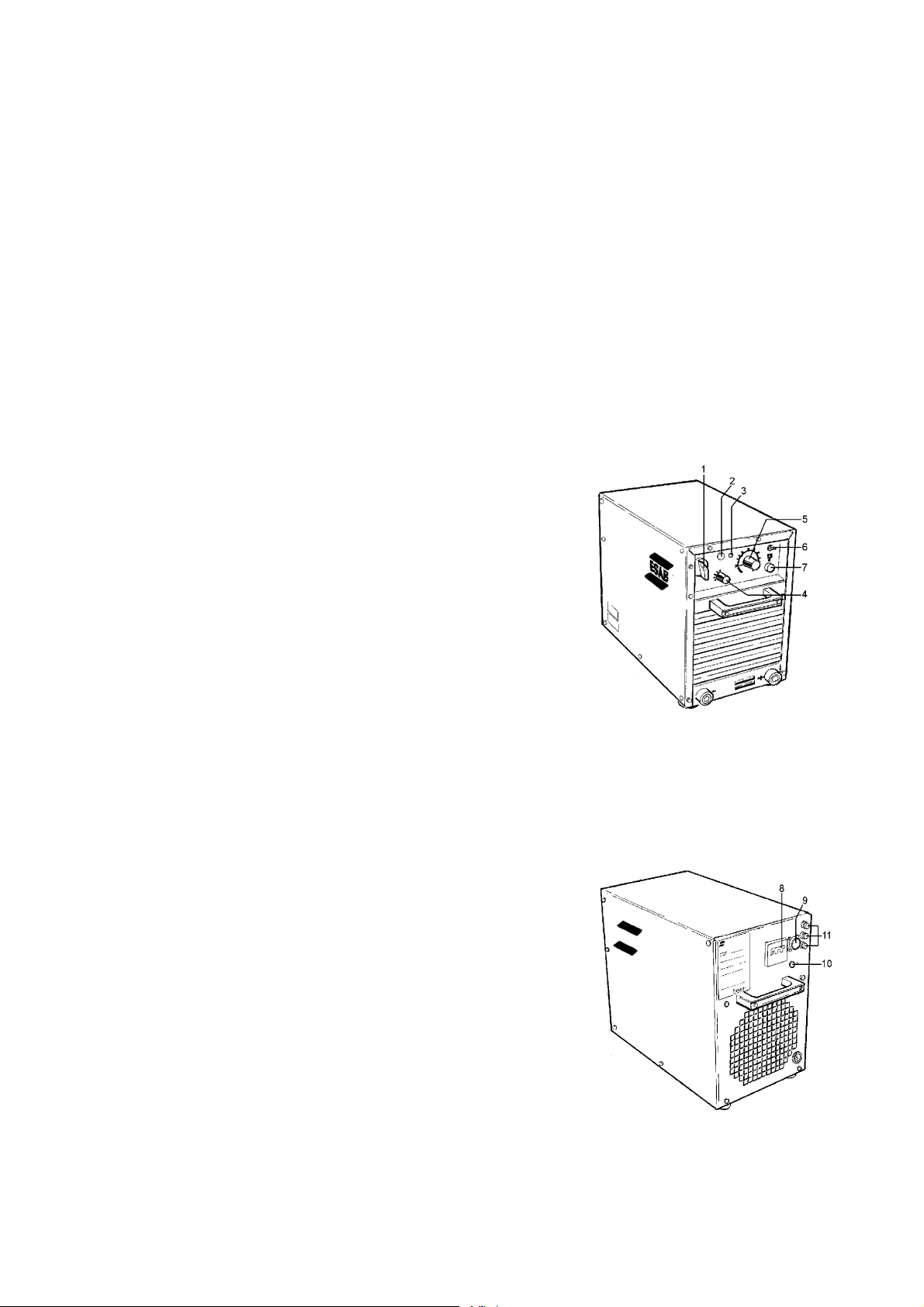
Регулирующие устройства на передней панели LUA:
1. Сетевой выклю чатель
2. Белая контрол ьная лампа, заго
рающаяся п ри вк лючении выпрям ителя.
3. Желтая контро льная лампа, заг
орающаяся при п ерегреве устан овки.
4. Переключател ь выбора вида св
арки( M IG/MAG, ММА или TIG).
5. Ручка регулир овки величины с
варочного тока . За сч¸т встроен ног о
планетарн ого редуктора м ожно производи
ть очень точную подстройку. Мех анизм
сцеплени я предохраняет от поломок регу
лятор при резки х поворотах руч ки вправо или вл ево.
6. Переключател ь управления с п анели выпрямит
еля на дистанци онное управлен ие.
7. Разъ¸м пульта дистанционног о управления.
bu07d00
1
Регулирующие устройства на задней панели LUA:
8. Предохраните ль автоматичес кого типа
для за щиты от перегру зок.
9. Разъ¸м кабеля управления под
ающего механиз ма при полуавто
матической сва рке.
10. Разъ¸м (220 В) для подключения бл
ока водяного ох лаждения OCD1 или б
лока TIG-AID аргоно-ду говой сварки.
11. Предохраните ли.
bu07d2r -- 8 --
bu07d00
2

5 РАБОТА УСТАНОВКИ
1. Выпрямитель должен быть установлен прямо на ровной поверхности.
2. Поставьте авт оматический пр едохранитель н а задней стенке в
положение I.
3. Поставьте сет евой выключате ль в положение I. При этом белая к
онтрольная лам па должна загор еться и вентиля тор включиться
4. Проверьте, что бы не было огран ичений для дост упа воздуха в си
стему вентиляц ии.
5. Поставьте пер еключатель вид а сварки в требу емое положение
( MIG/MAG, ММА или TIG). Для полуавтоматиче ской сварки (MIG/MAG) с
уществует 3 уста новки: от ”само й холодной ” свар ки (положение А) д
о ”самой горячей ”(положение С).
6. При ручной дуг овой сварке (MMA) ил и аргоно-дугово й сварке (TIG) управ
ление параметр ами ведется с па нели или с пульт а дистанционно
го управления п ри соответству ющем положении переключателя.
7. Для дистанцио нного управлен ия процессом по луавтоматическ ой
сварки (MIG/MAG) с па нели подающего механизма пере ключатель вида
управления дол жны быть в соотв етствующем пол ожении.
8. Точная настро йка величины св арочного тока п роизводится ру чкой на
передне й панели или пул ьтом дистанцио нного управлен ия
(См.Соответст вующую инструк цию).
9. Проверьте пра вильность подк лючения свароч ного и возвратн ого
кабелей.
1 0. Теперь выпрям итель готов к ра боте.
Инструкции по работе с подающим механизмом и блоком аргоно-дуговой
сварки TIG-AID прилагаю тся к соответствующему оборудованию.
Устройства безопасной работы
Как отмечалось ранее выпрямитель имеет автоматический предохранитель на
задней стенке.
При перегрузках этот предохранитель автоматически срабатывает и отключает
питание выпрямителя.
Для продолжения работы необходимо переключить предохранитель в
положение I. Если срабатывание предохранителя происходит слишком часто,
обратитесь в сервисную службу.
Для защиты от перегрева выпрямитель имеет встроенный т ермостат,
срабатывающий при превышении температуры выше допустимой. При этом
обесточиваются сварочные кабели и загорае тся ж¸лтая контрольная лампа.
При понижении температуры термостат автоматически включает
выпрямитель.
bu07d2r -- 9 --

6 ТЕХНИЧЕСКОЕ ОБСЛУЖИВАНИЕ
В зависимости от условий работы выпрямитель необходимо регулярно
продувать сухим сжатым воздухом пониженного давления. В противном
случае приток воздуха в систему вентиляции может нарушиться, что привед¸т
к перегреву установки.
ЗАКАЗ ЗАПАСНЫХ ЧАСТЕЙ
При заказе запасных частей, пожалуйста, укажите тип установки, серийный
номер, название и артикульный номер запасной детали. Это поможет
упростить заказ и ускорить отгрузку.
7 ПРИНАДЛЕЖНОСТИ
LUA 400 в мультивольтажном исполнении.
Стандартное исполнение LUA 400 рассчитано на подключение к сети 380-415
В. После установки специального модуля напряжения LUA 400 может быть
подключ¸н к сети:
220/380/415/500 V - 50 Hz è
220/380/440/550 V - 60 Hz.
Пульты дистанционного управления (ДУ)
Заказной ¹.
SPHB 1(ÄÓ) 367 317-880
SPHB 2 (ÄÓ) 367 318-880
SPHC 2 (ÄÓ) 367 620-880
SPHA 5(Импульсный блок)
ñ ðàçú¸ìîì Cannon 320 128-880
ñ ðàçú¸ìîì Burndy 367 970-880
SPHA 2 (блок Горячего старта) 367 601-880
SПрограммный блок PAB 6 367 308-880
SБлок заварки кратера PAC 8 367 305-880
SКороткоимпульсный блок PAD 3 367 502-880
bu07d2r -- 1 0 --

Подключения и удлинители кабеля
к блокам PHB 1, PHB 2, PHC 2, PHA 5 или PHA 2.
Заказной ¹.
S5 м соединительный кабель 367 144-881
S10м соединительный кабель 367 144-882
S25 м соединительный кабель 367 144-883
S25 м удлинительный кабель 367 662-880
к блокам PAB 6, PAC 8, PAD 3.
S5 ì, 367 144-884
S10 ì, 367 144-885
S16 ì, 367 144-886
Блок выключателя
Sнепрерывного включения 321170-880
Sкабельного соединения 321 170-881
Дополнительные принадлежности LUA:
Заказной ¹.
SТ ележка выпрямителя 365 1 87-880
SТележка для полуавтомата LUA (Basic)
Т ележка для полуавтомата 367 360-882
SLUA (С блоком водяного охлаждения) 367 360-880
S Тележка мультисистемная”JUMBO”
(С блоком водяного охлаждения и
приставкой TIG-AID) 367 360-881
STIG-AID I тележка 365 075-880
bu07d2r -- 1 1 --

ENGLISH
1SAFETY 13...........................................................
2 INTRODUCTION 13...................................................
2.1 Applications 14..............................................................
2.2 Manual welding 14...........................................................
2.3 MIG/MAG welding 14.........................................................
2.4 TIG welding 14...............................................................
3 TECHNICAL DESCRIPTION 15.........................................
3.1 Control system 15............................................................
3.2 TECHNICAL DATA 16........................................................
4 INSTALLATION 17....................................................
Controls on front panel of LUA: 17....................................................
Controls at rear of LUA: 17..........................................................
5 OPERATION 18.......................................................
Safety devices 18..................................................................
6 MAINTENANCE 19....................................................
Ordering spare parts 19.............................................................
7 ACCESSORIES 19....................................................
LUA 400 multi--voltage version. 19....................................................
Remote control 19..................................................................
Connection and extension cables 20..................................................
Optional accessories for LUA include: 20..............................................
DIAGRAM 21............................................................
SPARE PARTS LIST 22...................................................
TOCe
-- 1 2 --

1SAFETY
WARNING
ARC WELDING AND CUTTING CAN BE INJURIOUS TO YOURSELF AND OTHERS. TAKE PRECAUTIONS WHEN WELDING. ASK FOR YOUR EMPLOYER’S SAFETY PRACTICES WHICH SHOULD BE
BASED ON MANUFACTURERS’ HAZARD DATA.
ELECTRIC SHOCK -- Can kill
S Install and earth the welding unit in accordance with applicable standards.
S Do not touch live electrical parts or electrodes with bare skin, wet gloves or wet clothing.
S Insulate yourself from earth and the workpiece.
S Ensure your working stance is safe.
FUMES AND GASES -- Can be dangerous to health
S Keep your head out of the fumes.
S Use ventilation, extraction at the arc, or both, to keep fumes and gases from your breathing zone and
the general area.
ARC RAYS -- Can injure eyes and burn skin.
S Protect your eyes and body. Use the correct welding screen and filter lens and wear protective
clothing.
S Protect bystanders with suitable screens or curtains.
FIRE HAZARD
S Sparks (spatter) can cause fire. Make sure therefore that there are no inflammable materials nearby.
NOISE -- Excessive noise can damage hearing
S Protect your ears. Use ear defenders or other hearing protection.
S Warn bystanders of the risk.
MALFUNCTION -- Call for expert assistance in the event of malfunction.
READ AND UNDERSTAND THE INSTRUCTION MANUAL BEFORE INSTALLING OR OPERATING.
PROTECT YOURSELF AND OTHERS!
WARNING
This product is intended for industrial use. In a domestic environment this
product may cause radio interference. It is the user’s responsibility to take
adequate precautions.
2 INTRODUCTION
LUA 400 is a welding rectifier built on the inverter principle and designed for welding
with coated electrodes, TIG welding, semi--automatic welding and arc air gouging.
Advanced electronics permit rapid control, low energy consumption, excellent
welding characteristics and compensation for mains voltage fluctuation.
Inverter technology contributed to the low weight and compact dimensions of the
unit. The rating plate and connection information are located at the rear of the LUA.
LUA is supplied with two handles, connecting bolts, Allen key and cable couplings.
-- 1 3 --bu07d2e

2.1 Applications
LUA 400 is the ideal choice for those who require a single power source that permits
the use of all welding methods.
The basic unit, the LUA 400 power source, can be combined with ESAB standard
components to create a complete system for MIG/MAG, manual or TIG welding. This
instruction manual only describes the LUA 400 power source. (Order numbers for
complementary equipment can be found in the ”Accessories” section).
2.2 Manual welding
The high open circuit voltage and a carefully chosen ”start puff” at the beginning of
welding ensure a smooth start to the welding cycle and easy striking of electrodes.
The ”anti--freeze feature” of LUA greatly reduces the risk of the electrode sticking to
the work piece. If however the electrode does stick then the welding current is
automatically reduced so that the electrode can be freed without damage and
welding can continue immediately. This feature facilitates the welding of root beads
in particular and saves electrodes.
2.3 MIG/MAG welding
In the case of semi--automatic welding the power source must be combined with a
wire feed unit, welding gun and gas bottle.
The latest electronics have been used to produce a compact, manageable and
reliable semi --automatic supply with first class characteristics for MIG/MAG welding.
By using ESAB’s wide selection of semi--automatic components (wire feed units,
remote controls, welding guns, counterbalance arms and cooling units) you can
customise equipment to suit your welding requirements. ESAB’s special brochures
describe the wide selection of semi--automatic equipment and accessories.
2.4 TIG welding
When combined with ESAB’s TIG--AID and BTD TIG gun the LUA 400 is an excellent
unit for professional TIG welding.
Low current operation is essential for welding thin sheet metal. The LUA 400
satisfies this requirement, with a minimum welding current of just 15 A.
During TIG welding the ”start puff” and ”anti-- freeze” features should be switched off.
This is done by turning the rotary switch on the front panel
to the ”TIG” setting.
bu07d2e
-- 1 4 --

3 TECHNICAL DESCRIPTION
This is how the LUA inverter works.
The incoming 3 phase AC current is rectified. Then it is converted back into AC using
a much higher frequency than mains frequency. After transformation the current is
again rectified to give a DC supply for welding. The entire cycle is controlled by a
control circuit that gives the power source the desired static characteristic and
dynamic performance.
LUA is divided into four main sections:
S The control section on top, comprising the circuit card, controls and electronics.
S The fan compartment, containing the fan and power resistor.
S The remaining components are mainly divided into mains components and weld-
ing components.
3.1 Control system
The LUA control system used modern electronics to create a power source that has
excellent static and dynamic welding characteristics, high efficiency, high power
factor, low minimum current, start puff, anti--freeze, foldback, electrically insulated
remote control, compensation for mains fluctuations, etc.
-- 1 5 --bu07d2e

3.2 TECHNICAL DATA
Current setting range 15 A/20 V -- 400 A/36 V
TIG welding 15-- 400 A
Manual welding 20--400 A
Semi--automatic welding 45--400 A
Maximum load
Manual welding
-- at 35% duty cycle
-- at 60% duty cycle
-- at 100% duty cycle
TIG welding
-- at 35% duty cycle
-- at 60% duty cycle
-- at 100% duty cycle
Semi--automatic welding
-- at 35% duty cycle
-- at 60% duty cycle
-- at 100% duty cycle
Open circuit voltage 65-- 75 V
Open circuit power 0.06 kW
Power factor λ 0.94
Efficiency η 0.80
Enclosure class IP 23
400 A/36 V
315 A/32.6 V
150 A/26 V
400 A/26 V
315 A/22.6 V
250 A/20 V
400 A/34 V
315 A/30 V
200 A/24 V
Application class
Weight 48 kg
Mains supply
Voltage (V) 3x230 3x400 3x415 3x440 3x500 3x550
Frequency (Hz) 50/60 50/60 50 60 50 60
Primary current (A) 40 26 25 18 19 15
Fuse, slow (A) 35 20 20 20 20 20
Cable (mm2) 4x6 4x2.5 4x2.5 4x2.5 4x2.5 4x2.5
This welding power source complies with IEC 974--1
Mains cable complies with Swedish regulations.
The sym bol indicates the power source is designed for use in area of increased
electrical hazard.
The IP code indicates the degree of protection the casing provides against
penetration of solid objects and water.
Equipment marked IP 23 is designed for indoor and outdoor use.
bu07d2e
-- 1 6 --

4 INSTALLATION
Check that the welding power source is set up for the available main voltage before
connecting it to the supply.
The voltage is indicated on the rating plate at the rear of the power source.
LUA must be connected to a three phase mains supply.
LUA is supplied with a mains cable. The cable is connected to the terminals L1, L2
and L3 on terminal block K11. The phase sequence is not important. The cable
grommet and cable grip are located on the bottom right at the rear of the rectifier.
The equipment must be earthed in accordance with regulations.
Suitable welding and return cables for the LUA 400 are 50 mm2.
Controls on front panel of LUA:
1. Power switch
2. White lamp which lights up when rectifier
is switched on
3. Yellow lamp which lights up if power
source overheats
4. Rotary switch for selecting between
MIG/MAG, manual, or TIG welding
5. Knob for adjusting welding current.
Equipped with planetary gear to allow
fine adjustment. A sliding clutch prevents
damage caused if the knob is turned past
the min. or max. settings.
6. Toggle switch for selecting between current control on front panel or remote control
7. Socket for remote control
Controls at rear of LUA:
8. Automatic fuse which protects against
overloading and high current spikes
9. Socket for connecting wire feed unit and
MIG/MAG remote control
10. Socket for connecting OCD1 cooling unit
or TIG--AID (220 V)
bu07d001
11. Fuses
bu07d002
-- 1 7 --bu07d2e

5OPERATION
1. LUA must be placed upright.
2. Set the automatic fuse on the rear to setting I.
3. Set the power switch to setting I. The power lamp will light up and the fan will
start.
4. Check that there is no restriction in the flow of air.
5. Set the rotary switch to MIG/MAG, manual or TIG, as required. There are three
different MIG/MAG settings. A gives the ”coldest” weld and C gives the ”hottest”
weld.
6. In the case of MMA or TIG welding, set the toggle switch on the front panel to
allow direct or remote control of the welding current, as r equired.
7. In the case of MIG/MAG welding the remote control must also be connected to
the socket on the wire feed unit and the toggle switches on the wire feed unit and
the front panel must both be set to the appropriate setting.
8. Fine adjust the welding current using the knob on the front panel or using the remote control. See relevant instruction manual.
9. Check that the couplings on the welding cable and return cable are properly connectedtoLUA.
10. LUA is now ready to start welding.
Operating instructions for the wire feed unit and TIG--AID are supplied with that
equipment.
Safety devices
As mentioned previously there is an automatic fuse unit on the rear of the LUA
power source.
In the event of overloading or a high current spike this fuse trips automatically and
switches off the power.
To continue operation the automatic fuse must be reset to setting I. If the fuse trips
repeatedly you should call in a service engineer.
LUA is also equipped with a thermal overload switch that automatically switches off
the power in the event of overload or overheating (yellow lamp lights up). This is
reset automatically once the components have cooled down to an acceptable
temperature.
bu07d2e
-- 1 8 --

6 MAINTENANCE
Depending on the environment it is used in the power source should be blown clean
regularly using dry compressed air at reduced pressure. Otherwise blocked air
intakes or vents may lead to overheating.
Ordering spare parts
When ordering spare parts please state the machine model, serial number plus the
name and spare part number as shown in the list of spare parts.
This makes dispatch easier and ensures correct delivery.
7 ACCESSORIES
LUA 400 multi--voltage version.
LUA 400 is supplied as standard for connection to 380--415 V mains supplies. By
fitting a voltage module the LUA 400 can also be connected to the following supply
voltages:
220/380/415/500 V -- 50 Hz and
220/380/440/550 V -- 60 Hz.
Remote control
Order no.
S PHB 1 remote control 367 317--880
S PHB 2 remote control 367 318--880
S PHC 2 remote control 367 620--880
S PHA 5 pulse unit
with Cannon connector 320 128--880
with Burndy connector 367 970--880
S PHA 2 hot--start unit 367 601--880
S Programmer unit PAB 6 367 308--880
S Crater filling unit PAC 8 367 305--880
S Short pulse unit PAD 3 367 502--880
-- 1 9 --bu07d2e

Connection and extension cables
PHB 1, PHB 2, PHC 2, PHA 5 och PHA 2.
Order no.
S 5 m connecting cable 367 144--881
S 10 m connecting cable 367 144--882
S 25 m connecting cable 367 144--883
S 25 m extension cable 367 662--880
Remote control cable PAB 6, PAC 8, PAD 3.
S 5 m, 367 144--884
S 10 m, 367 144--885
S 16 m, 367 144--886
Switching unit
S For permanent connection. 321 170--880
S For cable connection. 321 170--881
Optional accessories for LUA include:
Order no.
S Trolley for power source 365 187--880
S LUA semi --trolley (Basic)
for power source and wire feed 367 360--882
S LUA semi--trolley (water)
for power source and wire feed 367 360--880
S LUA maxi--trolley ”JUMBO”
with space for cooling unit
and TIG--AID 367 360--881
S TIG-- M AID I trolley 365 075--880
bu07d2e
-- 2 0 --

Diagram Схема
bu07e001
-- 2 1 --bu07e12a


LUA 400 Edition 020311
Spare parts list Список запасных частей
Valid for serial no. 535--xxx--xxxx
Ordering numbers for LUA 400
0367 044 880 Welding power source 380 V, 50 Hz
0367 044 881 Welding power source 220/380 V, 50/60 Hz
0367 044 882 Welding power source 220/380/415/440/500/550 V, 50/60 Hz
0367 044 883 Welding power source 380/415 V, 50/60 Hz
Spare parts are to be ordered through the nearest ESAB agency as per the list on the back of the
cover. Kindly indicate type of unit, serial number, denominations and ordering numbers according to
the spare parts list.
Maintenance and repair work should be performed by an experienced person, and electrical work only
by a trained electrician. Use only recommended spare parts.
bu07s11a
-- 2 3 --

LUA 400 Edition 020311
Item
Qty Ordering no. Denomination Notes
101 0365 452 001 Side panel
102 0365 451 001 Cover plate
103 0318 113 001 Knob
104 0192 576 004 Lamp
105 0193 666 003 LED Yellow
106 0319 187 001 Indicator
107 0191 510 104 Knob
108 0147 866 001 Switch
109 0368 544 003 Socket
110 0468 883 001 Front sign
111 0192 296 104 Control knob
112 0367 240 881 Front plate
113 0160 362 881 Cable connection
114 0320 787 001 Cover
115 0467 290 001 Automatic cut out
116 0368 544 005 Socket Burndy
117 0567 901 116 Fuse 10 A
118 0567 900 113 Fuse 4A
119 0156 388 001 Handle
120 0367 098 002 Rear plate
121 0319 455 002 Foot
bu07s11a
-- 2 4 --

LUA 400 Edition 020311
bu07s11a
-- 2 5 --

LUA 400 Edition 020311
Item
Qty Ordering no. Denomination Notes
201 0191 309 107 Clamp
202 0341 609 880 Filter
203 0320 689 101 Resistor
204 0320 688 002 Diode
205 0367 030 880 Welding diode filter
206 0320 704 002 Capacitor
207 0367 577 880 Resistor
208 0320 870 880 Inductor
209 0367 033 880 Inductor
210 0365 348 880 Control transformer
211 0320 655 001 Thermostat
212 0320 729 001 Current transformer
213 0367 168 880 Diode bridge
214 0320 795 001 Fan
215 0320 558 880 Shunt
216 0320 655 002 Thermostat
217 0367 032 880 Mains transformer
218 0192 903 501 Capacitor
219 0367 020 880 Thyristor module filter
220 0193 542 001 Connection block
221 0367 127 880 Choke
222 0193 545 107 Capacitor
bu07s11a
-- 2 6 --

LUA 400 Edition 020311
bu07s11a
-- 2 7 --

LUA 400 Edition 020311
Item
Qty Ordering no. Denomination Notes
301 0191 870 212 Potentiometer 2,5 KÙ
302 0192 576 004 Lamp
303 0367 105 002 Switch
304 0467 356 880 Automatic fuse
305 0481 190 880 Circuit board
306 0320 724 001 Transformer
307 0191 085 102 Capacitor
308 0481 255 880 Circuit board
309 0481 343 882 Main circuit board
310 0192 927 102 Spacer
311 0147 866 001 Switch
0367 234 883 Autotransformer Contains items 312, 313, 314 and 315b
312 0365 551 002 Rear panel
313 0365 001 003 Cover
314 0365 000 881 Rear plate
315a 0367 235 001 T ransformer 220/380V
315b 0365 134 002 T ransformer 220/380/415/440/500/550 V,
315c 0368 175 001 Transformer 415/380 V
bu07s11a
-- 2 8 --

LUA 400 Edition 020311
bu07s11a
-- 2 9 --

LUA 400 Edition 020311
Item
Qty Ordering no. Denomination Notes
0365 187 880 Carriage
401 0365 255 880 Handle compl.
402 0320 939 002 Brakcet left
403 0320 939 001 Bracket right
404 0321 001 001 Ring
405 0365 255 881 Handle compl.
406 0218 801 202 Rubber handle Included in item 405 and 401
407 0365 066 001 Support
408 0366 451 001 Chassis
409 0365 068 003 Shaft
0215 701 019 Grooved ring D25x1,2
410 0366 516 001 Wheel
bu07s11a
-- 3 0 --

LUA 400 Edition 020311
Item
Qty Ordering no. Denomination Notes
0367 360 882 Carriage semi
501 0278 300 401 Insulating bushing
502 0318 170 001 Bracket
503 0321 173 001 Chain L=700
504 0365 388 001 Handle
505 0365 068 003 Shaft
506 0215 701 019 Grooved ring D25x1.2
507 0366 516 001 Wheel
508 0159 932 004 Swivel castor
bu07s11a
-- 3 1 --

LUA 400 Edition 020311
Item
Qty Ordering no. Denomination Notes
0367 360 880 Semi carriage
601 0278 300 401 Insulating bushing
602 0318 170 001 Bracket
603 0321 173 001 Chain L=700
604 0365 388 001 Handle
605 0365 068 003 Shaft
606 0366 516 001 Wheel
607 0215 701 019 Grooved ring D25x1.2
608 0159 932 004 Swivel castor
bu07s11a
-- 3 2 --

LUA 400 Edition 020311
Item
Qty Ordering no. Denomination Notes
0367 360 881 Semi carriage
701 0156 388 001 Handle
702 0156 389 001 Bar
703 0278 300 401 Insulating bushing
704 0318 170 001 Bracket
705 0321 173 001 Chain L=700
706 0366 516 001 Wheel
707 0215 701 019 Grooved ring D25x1.2
708 0365 068 003 Shaft
709 0159 932 004 Swivel castor
bu07s11a
-- 3 3 --

LUA 400 Edition 020311
Item
Qty Ordering no. Denomination Notes
0365 075 880 Trolley Tigaid 1
801 0321 173 001 Chain L=700
802 0159 932 001 Swivel castor
803 0365 038 001 Wheel
804 0365 046 001 Shaft
0215 701 019 Circlips
bu07s11a
-- 3 4 --


ESAB subsidiaries and representative offices
Europe
AUSTRIA
ESAB Ges.m.b.H
Vienna-- Liesing
Tel: +43 1 888 25 11
Fax: +43 1 888 25 11 85
BELGIUM
S.A. ESAB N.V.
Brussels
Tel: +32 2 745 11 00
Fax: +32 2 726 80 05
THE CZECH REPUBLIC
ESAB VAMBERK s.r.o.
Prague
Tel: +420 2 819 40 885
Fax: +420 2 819 40 120
DENMARK
Aktieselskabet ESAB
Copenhagen--Valby
Tel:+4536300111
Fax:+4536304003
FINLAND
ESAB Oy
Helsinki
Tel: +358 9 547 761
Fax: +358 9 547 77 71
FRANCE
ESAB France S.A.
Cergy Pontoise
Tel:+33130755500
Fax:+33130755524
GERMANY
ESAB GmbH
Solingen
Tel: +49 212 298 0
Fax: +49 212 298 204
GREAT BRITAIN
ESAB Group (UK) Ltd
Waltham Cross
Tel: +44 1992 76 85 15
Fax: +44 1992 71 58 03
ESAB Automation Ltd
Andover
Tel: +44 1264 33 22 33
Fax: +44 1264 33 20 74
HUNGARY
ESAB Kft
Budapest
Tel:+3612044182
Fax:+3612044186
ITALY
ESAB Saldatura S.p.A.
Mesero (Mi)
Tel:+3902979681
Fax:+390297289181
THE NETHERLANDS
ESAB Nederland B.V.
Utrecht
Tel: +31 30 248 59 22
Fax: +31 30 248 52 60
NORWAY
AS ESAB
Larvik
Tel:+4733121000
Fax:+4733115203
POLAND
ESAB Sp.z.o.o
Warszaw
Tel: +48 22 813 99 63
Fax: +48 22 813 98 81
PORTUGAL
ESAB Lda
Lisbon
Tel: +351 1 837 1527
Fax: +351 1 859 1277
SLOVAKIA
ESAB Slovakia s.r.o.
Bratislava
Tel:+421744882426
Fax:+421744888741
SPAIN
ESAB Ibérica S.A.
Alcobendas (Madrid)
Tel: +34 91 623 11 00
Fax: +34 91 661 51 83
SWEDEN
ESAB Sverige AB
Gothenburg
Tel:+4631509500
Fax:+4631509222
ESAB International AB
Gothenburg
Tel:+4631509000
Fax:+4631509360
SWITZERLAND
ESAB AG
Dietikon
Tel: +41 1 741 25 25
Fax: +41 1 740 30 55
North and South America
ARGENTINA
CONARCO
Buenos Aires
Tel: +54 11 4 753 4039
Fax: +54 11 4 753 6313
BRAZIL
ESAB S.A.
Contagem--MG
Tel: +55 31 333 43 33
Fax: +55 31 361 31 51
CANADA
ESAB Group Canada Inc.
Missisauga, Ontario
Tel: +1 905 670 02 20
Fax: +1 905 670 48 79
MEXICO
ESAB Mexico S.A.
Monterrey
Tel: +52 8 350 5959
Fax: +52 8 350 7554
USA
ESAB Welding & Cutting Products
Florence, SC
Tel: +1 843 669 44 11
Fax: +1 843 664 44 58
Asia/Pacific
AUSTRALIA
ESAB Australia Pty Ltd
Ermington
Tel: +61 2 9647 1232
Fax: +61 2 9748 1685
CHINA
Shanghai ESAB A/P
Shanghai
Tel: +86 21 6539 7124
Fax: +86 21 6543 6622
INDIA
ESAB India Ltd
Calcutta
Tel: +91 33 478 45 17
Fax: +91 33 468 18 80
INDONESIA
P.T. Esabindo Pratama
Jakarta
Tel: +62 21 460 01 88
Fax: +62 21 461 29 29
MALAYSIA
ESAB (Malaysia) Snd Bhd
Selangor
Tel: +60 3 703 36 15
Fax: +60 3 703 35 52
SINGAPORE
ESAB Singapore Pte Ltd
Singapore
Tel: +65 861 43 22
Fax: +65 861 31 95
ESAB Asia/Pacific Pte Ltd
Singapore
Tel: +65 861 74 42
Fax: +65 863 08 39
SOUTH KOREA
ESAB SeAH Corporation
Kyung--Nam
Tel: +82 551 289 81 11
Fax: +82 551 289 88 63
UNITED ARAB EMIRATES
ESAB Middle East
Dubai
Tel: +971 4 338 88 29
Fax: +971 4 338 87 29
Representative offices
BULGARIA
ESAB Representative Office
Sofia
Tel/Fax: +359 2 974 42 88
EGYPT
ESAB Egypt
Dokki--Cairo
Tel: +20 2 390 96 69
Fax: +20 2 393 32 13
ROMANIA
ESAB Representative Office
Bucharest
Tel/Fax: +40 1 322 36 74
RUSSIA--CIS
ESAB Representative Office
Moscow
Tel: +7 095 937 98 20
Fax: +7 095 937 95 80
ESAB Representative Office
St Petersburg
Tel: +7 812 325 43 62
Fax: +7 812 325 66 85
Distributors
For addresses and phone
numbers to our distributors in
other countries, please visit our
home page
www.esab.net
ESAB AB
SE--695 81 LAXÅ
SWEDEN
Phone +46 584 81 000
Fax +46 584 123 08
www.esab.net
020219
 Loading...