


PROWELDER 160
PROWELDER 250
LTS 160, LTS 250
Instruction manual Инструкция по эксплуатации
Valid for serial no. 008, 3060458 343 027 030324

Русский 3...............................................
ENGLISH 14..............................................
Rights reserved to alter specifications without notice.
Оставляем за собой право изменять спецификацию без предупреждения.
-- 2 --

Русский
1 ТЕХНИКА БЕЗОПАСНОСТИ 4........................................
2 ВВЕДЕНИЕ 5.......................................................
2.1 Состав оборудования 5....................................................
2.2 Программирующий блок управления 6.....................................
2.3 Применение 6.............................................................
3 ТЕХНИЧЕСКИЕ ДАННЫЕ 7..........................................
4 МОНТАЖ УСТАНОВКИ 8.............................................
4.1 Установка на рабочее место 8..............................................
4.2 Правила строповки 8.......................................................
4.3 Подключение к сети 9......................................................
4.4 Согласующее сопротивление 9.............................................
4.5 Подключение всех устройств системы сварки 10.............................
5ЭКСПЛУАТАЦИЯУСТАНОВКИ 11......................................
5.1 Управления и разъ¸мы 11...................................................
5.2 Блок водяного охлаждения 12...............................................
5.3 Защита от перегрева 12.....................................................
5.4 Предохранитель потока жидкости 12.........................................
5.5 Предохранитель потока защитного газа 12...................................
5.6 Сообщения об ошибках 12..................................................
6 ТЕХНИЧЕСКОЕ ОБСЛУЖИЕАНИЕ 13.................................
6.1 Осмотр и чистка 13.........................................................
7 ЗАКАЗ ЗАПАСНЫХ ЧАСТЕЙ 13.......................................
СХЕМА 26..............................................................
СПИСОК ЗАПАСНЫХ ЧАСТЕЙ 31........................................
ДОПОЛНИТЕЛЬНЫЕ ПРИНАДЛЕЖНОСТИ 47...........................
TOCr
-- 3 --

RU
1 ТЕХНИКА БЕЗОПАСНОСТИ
Пользователи сварочного оборудования ESAB отвечают за выполнение правил техники
безопасности лицами, работающими на оборудовании и рядом с ним. Правила техники
безопасности должны отвечать требованиям к безопасной эксплуатации сварочного
оборудования этого типа. Помимо стандартных правил техники безопасности и охраны
труда на рабочем месте рекомендуется следующее.
Все работы должны выполняться подготовленными лицами, знакомыми с эксплуатацией
сварочного оборудования. Неправильная эксплуатация оборудования может вызвать
опасным ситуации, приводящие к травмированию персонала и повреждению
оборудования.
1. Bсе лица, использующие сварочное оборудование, должны знать:
S инструкции по эксплуатации
S расположение органов аварийного останова
S назначение оборудования
S правила техники безопасности
S технологию сварки
2. Оператор обеспечивает:
S удаление посторонних лиц из рабочей зоны оборудования при его запуске
S защиту всех лиц от в оздействия сварочной дуги
3. Рабочее место должно:
S отвечать условиям эксплуатации
S не иметь сквозняков
4. Средства защиты персонала
S Во всех случаях рекомендуется использовать индивидуальные средства защиты,
например, защитные очки, огнестойкую спецодежду и защитные рукавицы.
S При сварке запрещается носить свободную одежду, украшения и т.д., например,
шарфы, б раслеты, кольца, которые могут попасть в сварочное оборудование или
вызвать ожоги.
5. Общие меры предосторожности
S Проверьте надежность подключения обратного кабеля.
S Работы на оборудовании с высоким напряжением должны производиться
только квалифицированным электриком.
S В пределах доступа должны находиться соответствующие средства
пожаротушения, имеющие ясную маркировку.
S Запреща ется проводить смазку и техническое обслуживание оборудование во
время эксплуатации.
dpb6d1ra
-- 4 --

RU
ОСТОРОЖНО!
ДУГОВАЯ СВАРКА И РЕЗКА ОПАСНЫ КАК ДЛЯ ИСПОЛНИТЕЛЯ РАБОТ, ТАК И ДЛЯ
ПОСТОРОННИХ ЛИЦ. ТРЕБУЙТЕ СОБЛЮДЕНИЕ
ДЕЙСТ
ПРЕДСТА
ОПАСНОСТЬ СМЕРТЕЛЬНОГО ПОРАЖЕНИЯ ЭЛЕКТРИЧЕСКИМ ТОКОМ.
S Сварочный агрегат устанавливается и заземляется в соответствии с действующими нормами и
S Не допускайте контакта находящихся под напряжением деталей и электродов с незащищенными
S Обеспечьте электрическую изоляцию от земли и свариваемых деталей.
S Обеспечьте соблюдение безопасных рабочих расстояний.
ДЫМЫ И ГАЗЫ могут быть опасны для человека
S Исключите возможность воздействия дымов.
S Для исключения вдыхания дымов во время сварки организуется общая вентиляция помещения, а
ИЗЛУЧЕНИЕ ДУГИ вызывает поражение глаз и ожоги кожи.
S Защитите глаза и кожу. Для этого используйте защитные щитки, цветные линзы и защитную
S Для защиты посторонних лиц применяются защитные экраны или занавеси.
ПОЖАРООПАСНОСТЬ
S Искры (брызги металла) могу т вызвать пожар. Убедитесь в отсу тствии горючих материа лов
∅УМ - Чрезмерный шум может привести к повреждению органов слуха
S Примите меры для защиты слуха. Используйте затычки для ушей или другие средства защиты
S Предупредите посторонних лиц об опасности.
НЕИСПРА
оборудованию
Â
УЮЩИХ НА ОБЪЕКТЕ, КОТОРЫЕ ДОЛЖНЫ УЧИТЫВАТЬ СВЕДЕНИЯ ОБ ОПАСНОСТЯХ,
Â
ЛЕННЫЕ ИЗГОТОВИТЕЛЕМ СВАРОЧНОГО ОБОРУДОВАНИЯ.
правилами.
частями тела, мокрыми рукавицами и мокрой одеждой.
также вытяжная вентиляция из зоны сварки.
спецодежду.
поблизости от места сварки.
слуха.
Â
НОСТИ -- При неисправности обратитесь к специалистам по сварочному
Â
СЕХ ПРАВИЛ БЕЗОПАСНОСТИ,
Перед началом монтажа и эксплуатации внимательно изучите соответствующие инструкции.
ЗАЩИТИТЕ СЕБЯ И ДРУГИХ!
2 ВВЕДЕНИЕ
LTS 160, LTS 250 сварочный источник питания, предназначенный для
механизированной аргоно-дуговой сварки (TIG).
Сварочный источник питания LTS имеет систему принудительного
воздушного охлаждения, а также встроенный блок водяного охлаждения
сварочной горелки.
LTS - имеет возможность подключения к внешнему персональному
компьютеру.
2.1 Состав оборудования
Установка LTS 160, LTS 250 поставляется в комплекте с:
S Программирующим блоком управления с соединительным кабелем (10 м)
S Возвратным кабелем (5м) со струбциной заземления
S Газовый шланг (2 м) с зажимом.
S Согласующее сопротивление
dpb6d1ra
-- 5 --

RU
S Инструкцию по программированию: Шведский, Английский, Немецкий,
Французский.
S PC плата
2.2 Программирующий блок управления
Блок управлен ия LTS позволяет:
S Создавать программу сварки с использованием различных сварочных
головок.
S Осуществлять сварку согласно заданных режимов.
S Хранить сварочные программы как во внутренней памяти
микропроцессора, так и во внешнем персональном компьютере.
S Осуществлять обмен данными между различными блоками управления.
S Производить настройку режимов при ручной сварке TIG.
Подробнее о программировании параметров сварки см. Инструкцию по
программированию
Инструкции по программированию выпущены на с ледующих языках:
ßçûê Артикульный
¹
Английский 0457 706 X74 Французский 0457 706 X76
Немецкий 0457 706 X75 Шведский 0457 706 X70
Итальянский 0457 706 X79 Финский 0457 706 X73
Норвежский 0457 706 X72 Датский
(действи-телен 990401)
Голландский
(дей-ствителен 990401)
Португальский
(действителен 990401)
0457 706 X77 Испанский
(дей-ствителен 990401)
0457 706 X80
ßçûê Артикульный
¹
0457 706 X71
0457 706 X78
2.3 Применение
Установка LTS может быть использована при сварке совместно с:
S Орбитальными трубосварочными головками
S Головками для приварки труб диаметром 12-60 мм к трубным доскам
S Установкой автоматической сварки A25STB с плавающей головкой
S Горелкой ручной TIG сварки.
Проволокоподающим механизмом, подключаемым к LTS.
Внешними устройствами вращения и перемещения деталей ( роликоопоры,
манипуляторы и т. д..), управляемыми блоком PAL 3.
Дополнительные принадлежности ESAB для механизированной и ручной
сварки см. Стр. 47.
dpb6d1ra
-- 6 --

RU
3 ТЕХНИЧЕСКИЕ ДАННЫЕ
LTS 160 LTS 250
Сетевое напряжение 230 V ±10%, 1∼ 50/60 Hz 400 V ±10%, 3∼ 50/60 Hz
Допустимая нагрузка при:
ÏÅ 35 %
ÏÅ 60 %
ÏÅ 100 %
Мощность холостого хода 50 W 55 W
Коэффициент мощности 0,68 0,61
Ê.Ï.Ä. ≥0,75 ≥0,75
Напряжение холостого хода 70 V 70 V
Òîê ïåðâ èöнойсетипри:
ÏÅ 100%
Поджиг при Å× Å×
Габариты,lxwxh
без охлаждающего агрегата
с охлаждающим агрегатом
Ååñ
без охлаждающего агрегата
с охлаждающим агрегатом
Темпер ат ур ны й к ла сс F (155 _C) F (155 _C)
160 A / 16 V
110A/15V
80 A / 13 V
9A 8A
515 x 285 x 620 mm
515 x 285 x 835 mm
37 kg
56,5 kg
250 A / 20 V
180 A / 17 V
140 A / 16 V
515 x 285 x 620 mm
515 x 285 x 835 mm
38 kg
57,5 kg
Класс защиты IP 23 IP 23
Класс применения
Диапазон регулирования
LTS 160 LTS 250
Рабочая зона, сварочный
ток
∅аг регулирования 1A 1A
Скорость подаöè
проволоки
Еремя импульса и паузы 0,01 -- 25,0 ñåê 0,01 -- 25,0 ñåê
Еремя подогрева 0 -- 600 ñåê 0 -- 600 ñåê
Предварительная
продувка, Конеöная
продувка
Нарастание и убывание
тока
Еремя сектора 0--10r 0--10r
∅аг регулирования
времени сектора
5 A / 10 V -- 160 A / 16 V 5 A / 10 V -- 250 A / 20 V
0.10--2.50 m/min 0.10--2.50 m/min
0 -- 6000 ñåê 0 -- 6000 ñåê
0,1 -- 25 ñåê 0,1 -- 25 s
0,001 r 0,001 r
Рабочий цикл
Рабочий цикл представляет собой долю (в %%) десятиминутного интерва ла, в течение
которой можно производить сварку при определенной нагрузке без перегрузки
источника питания сварочного агрегата.
dpb6d1ra
-- 7 --

RU
Класс кожуха
Нормы IP указывают класс кожуха, т.е., степень защиты от проникновения твердых
объектов и воды. Оборудование с маркировкой IP 23 предназначено для наружной и
внутренней установки.
Класс зоны установки
Этот символ означает, что источник питания предназначен для использования в зонах
с повышенной опасностью поражения электротоком.
4 МОНТАЖ УСТАНОВКИ
Ввод в эксплуатацию должен производиться квалифицированным
специалистом.
ВНИМАНИЕ!
Настоящее изделие предназначено для промышленного использования. При
использовании в бытовых условиях оно может создавать радиочастотные помехи.
Пользователь отвечает за принят ие соответствующих мер предосторожности.
4.1 Установка на рабочее место
Установите установку так, чтобы ничто не препятствовало притоку и оттоку
воздуха в системе вентиляции
4.2 Правила строповки
dpb6d1ra
-- 8 --

RU
4.3 Подклю÷åíèå ê ñåòè
S Убедитесь в том, что выпрямитель подсоединен к питающей сети
соответствующего напряжения с требуемым предохранителем.
Заземление согласно действующим нормам.
Табличка со схемой и данными по подключению находится
Rekommenderad kabelarea och säkringsstorlek
LTS 160 LTS 250
Сетевое напряжение 230 V 400 V
Вастота опустимсети 50--60 Hz 50--60 Hz
Плавкий предохранитель
Сечение кабеля,
16 A 16 A
3x2,5mm
2
4.4 Согласующее сопротивление
Для избежания возможных искажений в
коммуникации с обоих концов кабеля управления
CAN-bus необходимо установить согласующие
сопротивления.
Одно из них является встроенным в блок
управления. Другое устанавливается на разъ¸ме
задней стенки источника питания, как это показано
на рисунке, приведенном ниже.
4x1,5mm
2
dpb6d1ra
-- 9 --
RU
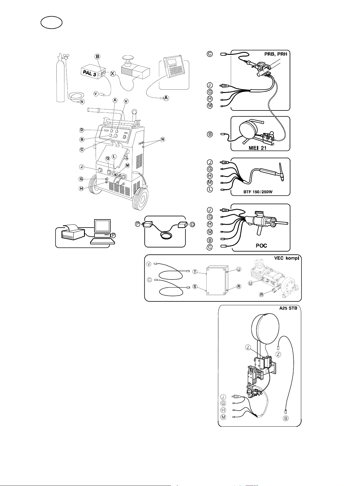
4.5 Подключение всех устройств системы сварки
A--A Соединительный кабель блока управления
B--B, Z--Z Соединительный кабель - подающего
механизма
C--C, S--S Соединительный кабель - вращения
D--D Соединительный кабель - от внешнего ПК
G--G Соединительный шланг системы водяного
охлаждения (Вход)
H--H Соединительный шланг системы водяного
охлаждения (Выход)
J--J Сварочный кабель
L--L Сеть управления горелки TIG
M--M Ãà ç î â û é ø ëà í ã ( Âõ îä )
N--N Ãà çî â û é ø ë à í ã ( Â û õî ä )
P--P Соединительный кабель - к внешнему ПК
Q--Q Разъ¸м возвратного кабеля (+)
R--R Соединительный кабель - передачи импульсов
T--T,V--V Соединительный кабель - CAN 42 В
X Соединительный кабель - внешний мотор
U--U Соединительный кабель - VEC мотор
dpb6d1ra
-- 1 0 --

RU
5ÝÊÑÏËÓÀÒÀÖÈßÓÑÒÀÍÎÂÊÈ
Общие правила техники безопасности при работе с оборудованием
приводятся на стр. 4. Прочтите их до использования оборудования!
5.1 Управления и разъ¸мы
1 Разъ¸м блока управления 11 Предохранитель 1.25 A (230 Е)
2 Разъ¸м CAN 42 В кабеля блока
управления PAL 3 и каб еля A25 VEC -мотора
3 Белая контрольная лампа напряжения
ñåòè
4 Оранжевая контрольная лампа
перегрузки
5 Выключатель системы водяного
охлаждения ВКЛ/ВЫКЛ
6 Штуцер защитного газа для поддува
корня шва (Еход)
7 Штуцер поступления защитного газа 17 Разъ¸м сварочного кабеля (-)
8 Штуцер предварительной газовой
защиты
9 Штуцер защитного газа для поддува
корня шва (Еыход)
10 Предохранитель 1.25 A (230 Е) 20 Разъ¸м к системе ПК/принтер
12 Разъ¸м кабеля системы водяного
охлаждения 230 V, 1.25 A
13 Разъ¸м предохранителя потока жидкости
14 Разъ¸м шланга защитного газа
15 Разъ¸м кабеля управления горелки
ручной сварки TIG
16 Разъ¸м возвратного кабеля (+)
18 Разъ¸м кабеля вращения
19 Разъ¸м подающего м еханизма
dpb6d1ra
-- 1 1 --

RU
5.2 Блок водяного охлаждени
ВНИМАНИЕ! Для того: чтобы охлаждающий агрегат
поместился под источником сварочного тока, следует
открутить ящик с инструментом на тележке .
Прикрутите охлаждающий агрегат на источнике
сварочного тока.
ÿ
5.3 Защита от перегрева
Установка имеет встроенный термостат, который предохраняет установку от
работы в режиме перегрева. При срабатывании термостата сварочная цепь
обесточивае тся и загорается оранжевый светодиод на передней панели
источника. На дисплее блока управления также появляется сообщение об
ошибке. При понижении температуры до нормального уровня,
восстанавливается напряжение в сварочной цепи и светодиод гаснет.
5.4 Предохранитель потока жидкости
При нарушении циркуляции жидкости в системе водяного охлаждения
предохранитель потока жидкости блокирует работу сварочной установки.
Сварочная цепь обесточивается и на дисплее блока управления также
появляется сообщение об ошибке.
Енимание. Предохранитель срабатывает, если система водяного охлаждения
была изначально включена переключателем 4 и шланги системы также были
подключены.
5.5 Предохранитель потока защитного газа
Предохранитель потока защитного газа обесточивает сварочную цепь при
расходе защитного газа менее 6 л/мин. На дисплее блока управления также
появляется сообщение об ошибке.
5.6 Сообщения об ошибках
Источник питания имеет встроенную функцию сообщений об ошибках. Есе
сообщения появляются на дисплее и в некоторых случаях происходит
самоустранение причин их вызвавших. Подробнее об этом См. Инструкцию
по программированию 0457 706 xxx.
dpb6d1ra
-- 1 2 --
RU
6 ТЕХНИЧЕСКОЕ ОБСЛУЖИЕАНИЕ
Примечание:
Âсе гарантийные обязательства поставщика теряют силу в случае попытки
покупателя самостоятельно устранить какую-либо неисправность машины в
течение гарантийного периода.
Подключение, обслуживание и ремонт сварочного оборудование, связанные
со снятием защитных щитков, выполняются лицами, прошедшими
соответствующую электротехническую подготовку и аттестованными на право
выполнения таких работ.
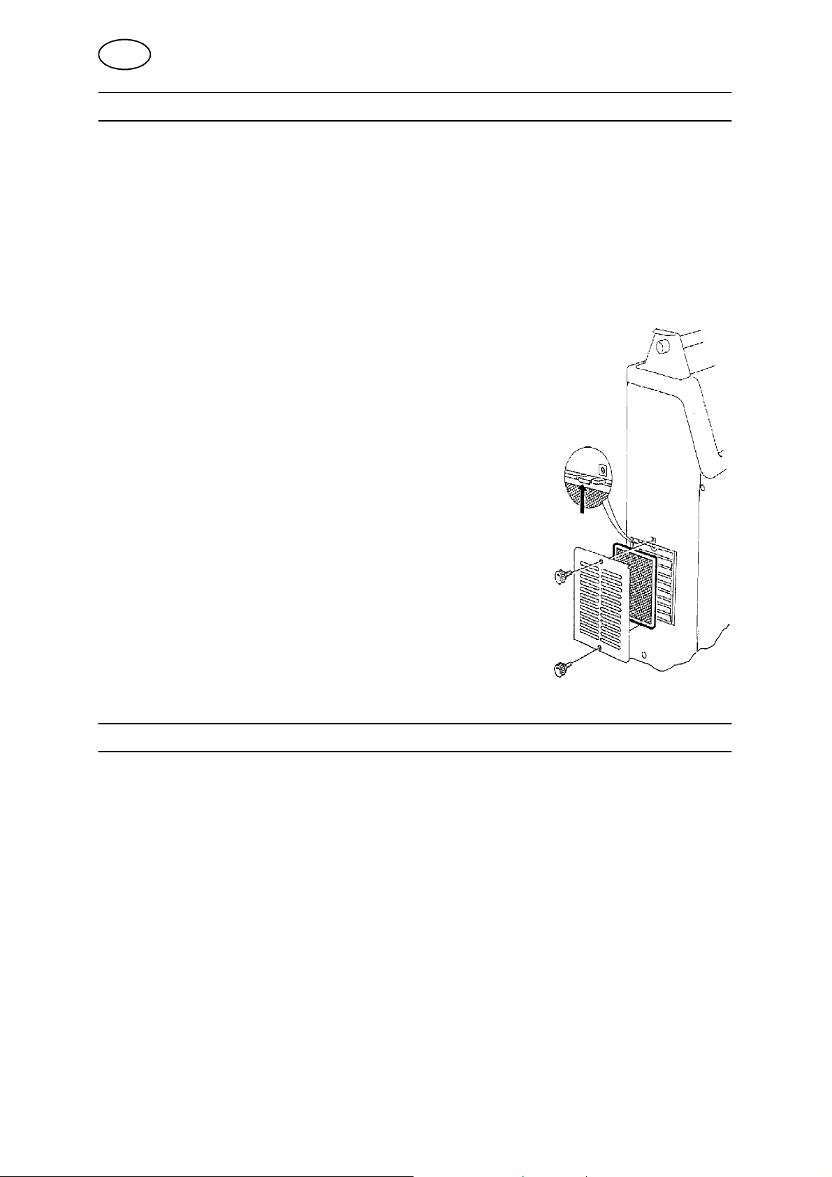
6.1 Осмотр и чистка
Е принципе LTS 160 / LTS 250 не требуют
специального обслуживания. Обыцно
достатоцно продувать установку цистым сжатым
воздухом и оцищать воздушный фильтр. Если
установка эксплуатируется в оцень загрязненных
условиях - фильтр надо оцищать как можно
цаще.
7 ЗАКАЗ ЗАПАСНЫХ ЧАСТЕЙ
Запасные части заказываются через ближайшее представительство ESAB,
адрес которого можно найти на последней странице обложки.
При заказе запасных частей укажите тип машины и ее номер, а также
наименование детали и ее номер из перечня запасных частей. Это упростит
доставку и обеспечит получение требуемых запасных частей.
dpb6d1ra
-- 1 3 --

ENGLISH
1DIREKTIV 15.........................................................
2SAFETY 15...........................................................
3 INTRODUCTION 16...................................................
3.1 Equipment 16................................................................
3.2 Programming box 17.........................................................
3.3 Applications 17..............................................................
4 TECHNICAL DATA 18.................................................
5 INSTALLATION 19....................................................
5.1 Lifting instructions 19.........................................................
5.2 Mains voltage connection 20...................................................
5.3 Termination resistans 20......................................................
5.4 Connection of complete welding system 21......................................
6 OPERATION 22.......................................................
6.1 Controls and connections 22...................................................
6.2 Cooling unit 23...............................................................
6.3 Overheating protection 23.....................................................
6.4 Flow guard, water 23.........................................................
6.5 Flow guard, gas 23...........................................................
6.6 Error messages 23...........................................................
7 MAINTENANCE 24....................................................
7.1 Check--up and cleaning 24....................................................
8 ORDERING OF SPARE PARTS 24......................................
DIAGRAM 26............................................................
SPARE PARTS LIST 31...................................................
ACCESSORIES 47.......................................................
TOCe
-- 1 4 --

GB
1DIREKTIV
ESAB Welding Equipment AB, S--695 81 Laxå, Sweden, gives its unreserved guarantee that welding
power source LTS 160, LTS 250 from serial number 008 complies with standard EN 60974--1, in accordance with the requirements of directive (73/23/EEC) and addendum (93/68/EEC) and with standard EN 50199 in accordance with the requirements of directive (89/336/EEC) and addendum
(93/68/EEC).
DECLARATION OF CONFORMITY
-- -- -- -- -- -- -- -- -- -- -- -- -- -- -- -- -- -- -- -- -- -- -- -- -- -- -- -- -- -- -- -- -- -- -- -- -- -- -- -- -- -- -- -- -- -- -- -- -- -- -- -- -- -- -- -- -- -- -- -- -- -- -- --------
Laxå 2000--04--17
Anders Birgersson
Managing Director
ESAB Welding Equipment AB
695 81 LAXÅ
SWEDEN Tel: + 46 584 81000 Fax: + 46 584 411924
2SAFETY
Users of ESAB welding equipment have the ultimate responsibility for ensuring that anyone who
works on or near the equipment observes all the relevant safety precautions. Safety precautions
must meet the requirements that apply to this type of welding equipment. The following recommendations should be observed in addition to the standard regulations that apply to the workplace.
All work must be carried out by trained personnel well--acquainted with the operation of the welding
equipment. Incorrect operation of the equipment may lead to hazardous situations which can result
in injury to the operator and damage to the equipment.
1. Anyone who uses the welding equipment must be familiar with:
S its operation
S location of emergency stops
S its function
S relevant safety precautions
S welding
2. The operator must ensure that:
S no unauthorised person is stationed within the working area of the equipment when it is
started up.
S no--one is unprotected when the arc is struck
3. The workplace must:
S be suitable for the purpose
S be free from draughts
4. Personal safety equipment
S Always wear recommended personal safety equipment, such as safety glasses, flame--proof
clothing, safety gloves.
S Do not wear loose--fitting items, such as scarves, bracelets, rings, etc., which could become
trapped or cause burns.
5. General precautions
S Make sure the return cable is connected securely.
S Work on high voltage equipment may only be carried out by a qualified electrician.
S Appropriate fire extinquishing equipment must be clearly marked and close at hand.
S Lubrication and maintenance must not be carried out on the equipment during operation.
dpb6d1ea
-- 1 5 --

GB
WARNING
ARC WELDING AND CUTTING CAN BE INJURIOUS TO YOURSELF AND OTHERS. TAKE PRECAUTIONS WHEN WELDING. ASK FOR YOUR EMPLOYER’S SAFETY PRACTICES WHICH SHOULD BE
BASED ON MANUFACTURERS’ HAZARD DATA.
ELECTRIC SHOCK -- Can kill
S Install and earth the welding unit in accordance with applicable standards.
S Do not touch live electrical parts or electrodes with bare skin, wet gloves or wet clothing.
S Insulate yourself from earth and the workpiece.
S Ensure your working stance is safe.
FUMES AND GASES -- Can be dangerous to health
S Keep your head out of the fumes.
S Use ventilation, extraction at the arc, or both, to take fumes and gases away from your breathing zone
and the general area.
ARC RAYS -- Can injure eyes and burn skin.
S Protect your eyes and body. Use the correct welding screen and filter lens and wear protective
clothing.
S Protect bystanders with suitable screens or curtains.
FIRE HAZARD
S Sparks (spatter) can cause fire. Make sure therefore that there are no inflammable materials nearby.
NOISE -- Excessive noise can damage hearing
S Protect your ears. Use earmuffs or other hearing protection.
S Warn bystanders of the risk.
MALFUNCTION -- Call for expert assistance in the event of malfunction.
READ AND UNDERSTAND THE INSTRUCTION MANUAL BEFORE INSTALLING OR OPERATING.
PROTECT YOURSELF AND OTHERS!
3 INTRODUCTION
LT S 160, LTS 250 are welding power sources of the rectifier type designed for
mechanised TIG welding.
They are fan--cooled and also includes a cooling system for water--cooling of the
welding tool.
They is prepared for connection to an external PC.
3.1 Equipment
LTS 160 and LTS 250 are supplied with:
S Programming box with connection cable (10 m)
S Return cable (5 m) with return cable clamp
S Gashose(2m)withhoseclamp.
S End resistor.
S Programming manual in swedish, english, german och french.
S PC card.
dpb6d1ea
-- 1 6 --

GB
3.2 Programming box
The welding power source is provided with a programming box for:
S Programming of welding procedures when welding with a welding tool.
S Executing a welding process.
S Storing welding program in an internal or external memory unit (PC card).
S Transferring welding programs between programming units.
S Setting of different parameter values when welding with a TIG hand torch.
For the handling, see Programming manual.
The programming manual is available in the following languages:
Language Article no. Language Article no.
English 0457 706 X74 French 0457 706 X76
German 0457 706 X75 Swedish 0457 706 X70
Italian 0457 706 X79 Finnish 0457 706 X73
Norwegian 0457 706 X72 Danish 0457 706 X71
Dutch 0457 706 X77 Spanish 0457 706 X78
Portuguese 0457 706 X80 Russian 0457 706 X86
3.3 Applications
Welding power source LTS can be used for welding with:
S Tube welding tools for joining tubes
S Tube--to--plate welding tools for welding of tube diameters 12--60 mm
S Automatic welding machine A25 STB with floating head.
S TIG hand torch
A wire feed unit for filler wire can be connected to the welding power sour ce.
Motors for external units (roller beds, turntables, etc.) can be controlled by way of the
PAL 3 motor control unit.
ESAB accessories for mechanised and manual T IG welding are found on
page 47.
dpb6d1ea
-- 1 7 --

GB
4 TECHNICAL DATA
LTS 160 LTS 250
Mains voltage 230 V ±10%, 1∼ 50/60 Hz 400 V ±10%, 3∼ 50/60 Hz
Permissible load at
35 % duty cycle
60 % duty cycle
100 % duty cycle
No--load power 50 W 55 W
Power factor 0,68 0,61
Efficiency ≥0,75 ≥0,75
No--load voltage 70 V 70 V
Primary current:
100% duty cycle
Arc strike HF HF
Dimensions l x w x h
without cooling unit
with cooling unit
Weight without cooling unit
with cooling unit
Temperature class F (155 _C) F (155 _C)
160 A / 16 V
110A/15V
80 A / 13 V
9A 9A
515 x 285 x 620 mm
515 x 285 x 835 mm
37 kg
56,5 kg
250 A / 20 V
180 A / 17 V
140 A / 16 V
515 x 285 x 620 mm
515 x 285 x 835 mm
38 kg
57,5 kg
Enclosure type IP 23 IP 23
Application class
Setting range
LTS 160 LTS 250
Operating range, current 5 A / 10 V -- 160 A / 16 V 5 A / 10 V -- 250 A / 20 V
Steps of adjustment, current 1A 1A
Wire feed speed 0.10--2.50 m/min 0.10--2.50 m/min
Pulse and background time 0.01 -- 25.0 s 0.01 -- 25.0 s
Pre--heat time 0 -- 600 s 0 -- 600 s
Gas pre-- and post--flow 0 -- 6000 s 0 -- 6000 s
Slope-- up and slope down 0,1 -- 25 s 0,1 -- 25 s
Sector 0--10r 0--10r
Steps of adjustment, sector
break point
Duty cycle
The duty cycle refers to the time as a percentage of a ten--minute period that you can weld at a certain load without overloading the welding power source.
0,001 r 0,001 r
Enclosure class
The IP code indicates the enclosure class, i. e. the degree of protection against penetration by solid
objects or water. Equipment marked IP 23 is designed for indoor and outdoor use.
Application class
The symbol indicates that the power source is designed for use in areas with increased
electrical hazard.
dpb6d1ea
-- 1 8 --

GB
5 INSTALLATION
The in stallatio n must be executed by a p rofessional.
WARNING!
This product is intended for industrial use. In a domestic environment this product may cause radio
interference. It is the user’s responsibility to take adequate precautions.
Place the welding power source so as not to prevent the cooling air from circulating
through the machine.
5.1 Lifting instructions
dpb6d1ea
-- 1 9 --

GB
5.2 Mains voltage connection
S Make sure the welding power source is connected to the right mains voltage and
that it is properly fused. Connect to earth according to the regulations valid.
The rating plate with connection data.
Recommended cable areas and fuse sizes
LTS 160 LTS 250
Mains voltage 230 V 400 V
Mains frequence 50--60 Hz 50--60 Hz
Fuse, slow--blow 16 A 16 A
Cable area
3x2,5mm
2
4x1,5mm
2
5.3 Termination resistans
To avoid communication trouble the two end points of
the CAN --bus should be fitted with an termination
resistans. One of the CAN--bus end points is in the
programming box which has a built-- in resistor. The
other one is in the power source and should be fitted
with an termination resistans if the output in question is
not used. For the location of the resistor, see the
following figure.
dpb6d1ea
-- 2 0 --

GB
5.4 Connection of complete welding system
A--A Connection cable -- programming box
B--B, Z--Z Motor cable --wire feed
C--C, S--S Motor cable -- rotation
D--D Signal cable -- external PC
G--G Cooling--water hose in
H--H Cooling--water hose out
J--J Welding cable
L--L Torch contact
M--M Gas hose out
N--N Gas hose in
P--P Signal cable -- external PC
Q--Q Return cable +
R--R Connection cable -- pulsetransmitter
VEC
T--T,V--V Connection cable -- CAN 42 V
X Connection cable -- external motor
U--U Connection cable -- rotor VEC
dpb6d1ea
-- 2 1 --

GB
6 OPERATION
General safety regulations for the handling of the equipment can be found on
page 15. Read through before you start using the equipment!
6.1 Controls and connections
1 Connection for programming box 11 Fuse, slow rupture 1.25 A
(connection 230 V)
2 Connection CAN 42 V for motor control unit
PAL3 and A25 VEC motor
3 White indicating lamp, mains voltage ON 13 Connection for flow--guard, (water)
4 Orange indicating lamp, overheating 14 Connection for welding and start gas out
5 Switch for mains voltage ON/OFF 15 Connection for torch contact, TIG hand torch
6 Connection for root gas in 16 Connection for return cable (+)
7 Connection for welding gas in 17 Connection for welding cable (--)
8 Connection for start gas in 18 Connection for rotation
9 Connection for root gas out 19 Connection for wire feed
10 Fuse, slow rupture 1.25 A
(connection 230 V)
12 Connection for cooling unit 230 V, 1.25 A
20 Connection for PC/printer
dpb6d1ea
-- 2 2 --

GB
6.2 Cooling unit
N.B. To give room for the cooling unit under the welding
power source, the tool box on the carriage must be
dismounted.
Screw the cooling unit and the welding power source
together.
6.3 Overheating protection
The LTS is provided with a thermal cut--out which trips in case of too high
temperature. The welding current is interrupted and an orange indicating lamp on the
front of the power source lights up. The programming box also shows an error
message. The thermal cut--out is reset automatically when the unit has cooled down.
6.4 Flow guard, water
If there is no cooling water flowing, the flow guard will block the welding power
source. The welding current is then interrupted and an error message is displayed in
the character window of the programming unit.
6.5 Flow guard, gas
The flow guard interrupts the ongoing welding process if the gas flow falls below 6
l/min. An error message is displayed by the programming box.
6.6 Error messages
The welding power source has a built-- in function for handling error messages. All
error messages are presented in the programming box, and in some cases
measures will be taken automatically. See also program ming manual 0457 706 xxx.
dpb6d1ea
-- 2 3 --

GB
7 MAINTENANCE
Note:
All warranty undertakings given by the supplier cease to apply if the customer
attempts to rectify any faults on the machine during the warranty period.
Only those persons who have appropriate electrical knowledge (authorised
personnel) may remove the safety plates to connect or carry out service,
maintenance or repair work on welding equipment.
7.1 Check--up and cleaning
Generally LTS 160 and LTS 250 does not require any
maintenance. Normally, it is sufficient to blow out the
machine using clean, compressed air (reduced pres sure) annually, and the dust filter should be cleaned
regularly. If the machine is set up in dusty or dirty
environment the machine and the dust filter should
be cleaned more often.
Dismounting the filter
8 ORDERING OF SP ARE PARTS
LTS 160, LTS 250 is designed and tested in accordance with the EN 60974--1 (IEC
50199) international standard.
It is the obligation of the service unit which has carried out the service or repair work
to make sure that the product still conforms to the said standard.
Spare parts are ordered through your nearest ESAB representative, see back cover.
When ordering spare parts, please state machine type and number as well as designation and spare part number as shown in the spare parts list.
This will simplify dispatch and ensure you get the right part.
dpb6d1ea
-- 2 4 --

sida
-- 2 5 --

Diagram Схема
dpb6e11a
-- 2 6 --

dpb6e11a
-- 2 7 --

dpb6e11a
-- 2 8 --

dpb6e11a
-- 2 9 --

sida
-- 3 0 --

LTS 160,LTS 250
Edition
Spare parts list Список запасных частей
030302
Valid for serial no. 008--xxx--xxxx to serial no. 306--xxx--xxxx
Ordering numbers for LTS 160 and LTS 250
0458 300 880 LTS 160 (PROWELDER 160)
0458 300 881 LTS 250 (PROWELDER 250)
Spare parts are to be ordered through the nearest ESAB agency as per the list on the back of the
cover. Kindly indicate type of unit, serial number, denominations and ordering numbers according to
the spare parts list.
Maintenance and repair work should be performed by an experienced person, and electrical work only
by a trained electrician. Use only recommended spare parts.
dpb6r11a
-- 3 1 --

LTS 160,LTS 250
Edition
030302
160 = LTS 160 250 = LTS 250
Qty
Qty
Item
160
101 1 1 0468 543 880 Handle Complete
102 1 1 0468 529 001 Rubber mat
103 1 1 0468 278 001 Cover When the cover is replaced, items 104 and
104 10 10 0192 859 006 Locking washer Must be pressed with 50 kg pressure, when
105 2 2 0468 532 001 Screw
106 2 2 0193 392 119 Insulating bushing
107 1 1 0469 402 880 Rubber seal 12 pcs of item 104 included
108 1 1 0458 317 880 Front panel Without components. When replaced, also
109 1 1 0458 292 880 Side panel
110 2 2 0441 819 001 Screw
111 1 1 0468 275 001 Grill
112 1 1 0468 519 001 Filter
113 1 1 0458 291 880 Side panel
114 1 1 0212 602 208 Nut
115 1 1 0193 307 104 Cable bushing
116 1 -- 0369 761 001 Mains cable 3x2.5mm2with plug
-- 1 0468 516 882 Mains cable 4x1.5mm
117 1 1 0320 787 001 Protection cap
118 4 4 0319 455 002 Rubber foot
119 1 -- 0458 294 880 Front cover
-- 1 0458 294 881 Front cover
1 1 0458 293 001 Rear panel
120 1 1 0457 348 880 Holder
121 2 2 0466 484 001 Fuse holder Includes item 123
122 2 2 Fuse 1.25 A slow FU8, FU9
123 2 2 Fuse holder cap Included in item 121
124 1 1 0458 301 001 Control transformer Includes FU1, FU2, FU3, FU4. TC1
1 1 Fuse 2 A slow. Included in item 124 FU1, FU3
1 1 Fuse 3.15 A slow. Included in item 124 FU2
1 1 Fuse 800 mA slow. Included in item 124 FU 4
125 0192 562 103 Cage nut M5
Ordering no. Denomination Notes
250
C = component designation in the circuit diagram
C
107 must also be replaced
fitted
replace items 104 and 107
2
dpb6r11a
-- 3 2 --

LTS 160,LTS 250
Edition
030302
dpb6r11a
-- 3 3 --

LTS 160,LTS 250
Edition
Qty Ordering no. Denomination Notes C
Item
201 1 0369 733 008 Indicating lamp White, 28 V HL1
202 1 0369 733 005 Light--emitting diode Orange V5
203 1 0458 358 882 Cabel complete Includes items 204 and 204b CONTR--E
204 1 0368 544 003 Connector socket 12--pole. Included in 203 XS37
204b 1 Connector 9--pole, D--sub. Included in item 203 XP4
205 1 0366 285 001 Cap
206 1 0458 358 883 Cabel complete Includes items 207 and 207b. C-- AUX
207 1 0368 544 003 Connector socket 12--pole. Included in 206. XS44
207b 1 Connector 9--pole, D--sub. Included in item 206 XP10
208 1 0366 285 001 Cap
209 1 0458 358 880 Cabel complete Includes items 210 and 210b.
210 1 0368 544 003 Connector socket 12--pole. Included in 209. XS49
210b 1 0193 260 007 Connector 8--pole. Included in item 209 XS39
211 1 0366 285 001 Cap
212 1 0458 358 881 Cabel complete Includes items 213 and 213b
213 1 0368 544 005 Connector socket 23--pole. Included in 212. XS48
213b 1 0193 260 130 Connector 12--pole. Included in item 212 XS40
214 1 0455 516 001 Cap
215 1 0366 295 004 Switch QF1
216 1 0366 296 002 Knob
217 1 0456 902 880 Cable Connectors included
1 Connector 25-- pole, D--sub. Included in item 217 XS45
1 Connector 9-- pole, D--sub. Included in item 217 XP13
218 1 0457 518 001 Gasket
219 1 0193 052 955 Securing strap L=100 mm
220 1 0193 052 950 Locking device
221 1 0193 052 932 Metal cap
222 1 0457 547 001 Gasket
223 2 0193 052 960 Male screw locks
224 4 0456 686 880 Clamp
225 Nut M3
030302
dpb6r11a
-- 3 4 --

LTS 160,LTS 250
Edition
030302
dpb6r11a
-- 3 5 --

LTS 160,LTS 250
Edition
030302
160 = LTS 160 250 = LTS 250
Qty
Qty
Item
160
301 1 1 0486 790 880 Circuit--board AP4
302 1 1 0486 476 880 Circuit--board TIG AP6
303 7 7 0192 927 104 Spacer Plastic
2 2 0394 516 020 Spacer Metal
304 1 1 0367 268 001 HF unit AP11
305 5 5 0365 534 001 Spacer washer Rubber washer
306 2 2 0192 859 006 Locking washer
307 1 1 0468 527 001 Holding plate
308 2 2 0365 584 002 Nail
309 1 1 0455 043 880 HF--coil TV1
310 2 2 0193 312 101 Ferrite core
311 1 -- 0486 343 881 Circuit board Suppression board AP5
-- 1 0486 577 880 Circuit board Suppression board AP5
312 1 1 0458 298 880 Holding plate
313 1 -- 0468 545 001 Sign
-- 1 0468 545 002 Sign
314 1 -- 0193 045 003 Terminal block 4--pole XT1
-- 1 0193 045 004 Terminal block 5--pole XT1
315 1 1 0193 045 002 Terminal block 3-- pole XT3
316 1 -- 0467 809 880 Primary inductor L3
1 -- 0040 953 611 Cable tie Heat resistant (to be used for item 316)
317 1 1 0468 521 001 Insulation
318 -- 1 0457 519 001 Fan 24V DC EV2
319 1 1 0538 500 902 Connector socket 2-- pole XS31
320 1 1 0457 626 001 Cap
321 2 2 0156 868 880 Welding current connector XS13, XS14
322 2 2 0468 548 001 Busbar G+F
323 1 -- 0367 269 880 Capacitor 0.1µF 400V with cable lugs (M6+M10) C6
-- 1 0367 269 882 Capacitor 0.1µF 275V AC X2 with cable lugs
324 1 -- 0468 534 881 Capacitor 0.1µF 400V PME with cable lugs (2xM10) C7
-- 1 0468 534 882 Capacitor 0.1µF 400V PHE427 with cable lugs (2xM10) C7
325 1 1 0468 534 880 Resistor 3.9kΩ 5W with cable lugs (2xM10) R1
326 2 2 0466 325 001 Gasket
327 1 1 0193 260 001 Connector 2pole XS7, XS10,
1 1 0193 260 152 Connector 4pole XS32
1 1 0193 260 150 Connector 2pole XS33
1 1 0193 260 157 Connector 9pole XS34
328 1 1 0190 315 102 Hose L=0.62 metre. To be ordered per metre.
329 1 1 0365 803 002 Nipple
330 1 1 0456 749 001 Connection socket XS12
331 1 1 0456 749 002 Connector Included in the cooling unit
332 1 1 0457 230 001 Panel jack XS53
333 1 1 0457 229 001 Support
334 1 1 0457 228 880 Cover
Ordering no. Denomination Notes
250
C = component designation in the circuit diagram
(M6+M10)
C
C6
XS11
dpb6r11a
-- 3 6 --

LTS 160,LTS 250
Edition
030302
dpb6r11a
-- 3 7 --

LTS 160,LTS 250
Edition
030302
160 = LTS 160 250 = LTS 250
Qty
Qty
Item
160
401 1 1 0468 310 001 Insulation
402 2 2 0468 279 001 Insulation
403 1 1 0468 280 001 Insulation
404 1 1 0468 546 001 Busbar
405 1 1 0468 538 001 Busbar
406 1 1 Busbar Included in item 550 and 650
407 1 1 Busbar Included in item 550 and 650
408 1 2 0192 903 506 Capacitor 1000µF C2, C3
409 -- 1 Connection bar Included in item 550 and 650
410 1 1 Busbar Included in item 550 and 650
411 1 1 Busbar Included in item 550 and 650
412 1 1 Busbar Included in item 550 and 650
413 1 1 0040 953 603 Cable tie Heat resistant
414 1 1 0486 166 880 Circuit board Shunt amplifier AP10
415 1 1 0193 260 152 Connector 4--pole XS19
416 4 4 0366 588 001 Nut
417 1 1 0468 274 001 Holding plate
418 2 2 0468 520 001 Grill
Ordering no. Denomination Notes
250
C = component designation in the circuit diagram
C
dpb6r11a
-- 3 8 --

LTS 160,LTS 250
Edition
030302
dpb6r11a
-- 3 9 --

LTS 160
Edition
C = component designation in the circuit diagram
Qty Ordering no. Denomination Notes
Item
501 1 0467 801 001 Fan 24 VDC EV1
502 1 Circuit board Transistor board, positive pole.
503 1 0192 883 150 Capacitor 0.1 µF1000VDC C1
504 1 0193 316 208 Rectifier bridge V1
505 1 0467 800 001 Insulation
506 2 0467 797 001 Guide
507 2 0467 793 180 Heat sink
Included in item 552
030302
C
AP2
508 1 Circuit board Transistor board, negative pole
-- 2 0193 260 001 Connector 2--pole XS15, XS16
509 15 Spring Included in item 552
510 1 0468 016 880 Inductor Secondary L1
511 1 0192 716 004 Diode V6
512 2 0193 529 017 Capacitor 4.7 µF C5
513 1 0468 496 001 Holder
514 1 0468 215 880 Inductor Complete L2
515 1 Winding Included in item 514
516 1 Bobbin Included in item 514
517 2 Core Included in item 514
518 2 Clip Included in item 514
519 1 0468 961 880 Shunt 119 mV at 140 A RS1
520 1 0192 883 017 Capacitor 0.1µF 400 VDC C4
521 2 0212 913 108 Spacer M8
522 1 0468 211 001 Busbar
523 1 0320 655 009 Thermal cutout Opens at 130˚C, closes at 100˚C
524 1 0467 792 880 Transformer coil Includes item 523 TC2
-- 1 0466 602 001 Conductor To be ordered per metre 0.6m/transformer 020
525 1 0467 799 001 Clip
526 4 0193 312 101
527 1 0193 669 002 Connector 2-- pole XS17
528 1 0455 646 880 Rectifier unit Complete, includes items 529 -- 534
529 1 0457 292 001 Heat sink
530 1 0193 948 001 Diode module V3, V4
531 1 0455 650 002 Busbar
532 1 0455 650 001 Busbar
533 2 0455 569 002 Ferrite ring core L4, L5
534 2 0040 953 612 Panduit strip Heat resistant
0365 652 002
0191 124 021
0193 590 302 Sleeve 2 per connector
Ferrite core
Tape
Glue
Included in item 552
Included in item 524
For air gap
Loctite 649, for ferrite core
AP3
ST1
SPARE PARTS SETS
Item Ordering no. Denomination Notes
550 0468 881 880 Busbars, primary Contains items 406, 407, 410, 411 and 412
552 0468 881 882 Transistor boards Contains items 502, 508 and 15 springs (item 509)
553 0192 058 106 Contact oil To be used when mounting item 502, 508 and 530
-- 4 0 --
dpb6r11b

LTS 160
Edition
030302
dpb6r11b
-- 4 1 --

LTS 250
Edition
C = component designation in the circuit diagram
Qty Ordering no. Denomination Notes C
Item
601 1 0467 801 001 Fan 24V DC EV1
602 1 Circuit board Transistor board positive pole
603 1 0192 883 150 Capacitor 0.1 µF 1000 VDC C1
604 2 0193 316 208 Rectifier bridge V1, V2
605 1 0467 800 001 Insulation
606 2 0467 797 001 Guide
607 2 0467 793 180 Heat sink
608 1 Circuit board Transistor board negative pole
-- 2 0193 260 001 Connector 2--pole XS15, XS16
609 19 Spring Included in item 651
610 1 0468 016 881 Inductor Secondary (item 625 is included) L1
611 1 0192 716 004 Diode V6
612 2 0193 529 017 Capacitor 4.7 µF C5
613 1 0468 496 001 Holder
614 1 0468 215 880 Inductor Complete L2
615 1 Winding Included in item 614
616 1 Bobbin Included in item 614
617 2 Core Included in item 614
618 2 Clip Included in item 614
619 1 0457 304 880 Shunt 1 19 mV at 250 A RS1
620 1 0457 557 880 Resistor Complete 8,2 kΩ 5W R2
621 1 0320 805 886 Capacitor 0.1µF 400 VDC C4
622 2 0468 538 002 Bus bar
623 2 0212 913 108 Spacer M8
624 1 0468 211 001 Bus bar
625 1 0320 655 009 Thermal cutout Opens at 130˚C,
626 1 0457 308 880 T ransformer coil TC2
-- 1 0466 602 001 Conductor Tobe ordered per metre 0.6 m/transformer 020
627 1 0467 799 001 Clip
628 4 0193 312 101 Ferrite core
0365 652 002 Tape For air gap
0191 124 021 Glue Loctite 649, for ferrite core
629 1 0193 669 002 Connector 2--pole XS17
0193 590 302 Sleeve 2 per connector
630 1 0455 569 003 Ferrite ring core L3
631 1 0455 646 883 Rectifier unit Complete, includes items 632, 633 and 637--640
632 1 0457 292 001 Heat sink
633 2 0193 948 001 Diode module V3, V4
634 1 Bus bar
635 1 Bus bar
636 2 0455 650 002 Bus bar
637 2 0455 569 002 Ferrite ring core L4, L5
638 2 0467 648 884 Capacitor Complete with cable lugs C10
639 2 0040 953 612 Panduit strip Heat resistant
640 2 0455 650 003 Bus bar
Included in item 651
Included in item 651
Included in item 610
030302
AP2
AP3
ST1
SPARE PARTS SETS
Item Ordering no. Denomination Notes
650 0468 881 880 Bus bars, primary Contains items 406, 407, 410, 411 and 412
651 0468 881 887 Transistor boards Contains items 602, 608 and 21 springs (item 609)
653 0192 058 106 Contact oil To be used when mounting items 602, 608 and 633.
-- 4 2 --
dpb6r11c

LTS 250
Edition
030302
dpb6r11c
-- 4 3 --

LTS 160,LTS 250
Edition
030302
160 = LTS 160 250 = LTS 250
Qty
Qty
Item
160
701 3 3 0193 054 002 Solenoid valve 42 V YV1, YV2, YV3
702 -- -- 0190 315 102 Gas hose D11/4,8, to be ordered per metre
703 5 5 0192 713 001 Hose nipple
704 1 1 0456 666 001 Muff
705 2 2 0456 654 001 Nipple 3/16“, M5
706 1 1 0413 154 002 Gas flow switch SL2
707 1 1 0456 664 001 T-- piece
708 1 1 0468 547 881 Capacitor 0.1 ìF, 250 V C9
709 1 1 0466 884 003 Terminal block 3--pole XT2
710 3 3 0441 819 002 Knob
711 8 8 0194 019 005 Spacer
712 1 1 0456 914 882 Cable Connectors XP8 and XP9 are included D-- H
713 1 1 0458 357 881 Cable Connectors XP1 and XP5 are included A-- C
714 Cable See item 217 XS45, XP13
715 Cable See item 206 XS44, XP10
716 1 1 0455 543 001 Top box
717 1 1 0486 764 884 Circuit board Data interface
718 1 1 0455 542 001 Bottom box
719 2 2 0456 661 001 Top box
720 1 1 0486 410 880 Circuit board AP9
721 2 2 0456 662 001 Box bottom
722 3 3 0194 019 003 Spacer
723 1 -- 0486 784 880 Circuit board AP1
-- 1 0486 784 882 Circuit board AP1
724 2 2 0193 260 150 Connector 2--pole XS1, XS41
1 1 0193 260 063 Connector 4--pole XS4
4 4 0193 260 152 Connector 4--pole XS2, XS3, XS9,
2 2 0193 260 061 Connector 2--pole XS6, XS18
1 1 0193 260 151 Connector 3--pole XS5
725 3 3 0192 562 103 Cage nut M5
726 1 1 0458 357 880 Cable Connectors XP3 and XP2 are included F--B
-- 6 6 Connector 9--pol, D--sub. Included in items 712, 713
Ordering no. Denomination Notes C
250
Replacing circuit board 0486 442 884
and 726
C = component designation in the circuit diagram
AP8
XS20
XP1, XP2, XP3,
XP5, XP8, XP9
dpb6r11d
-- 4 4 --

LTS 160,LTS 250
Edition
030302
dpb6r11d
-- 4 5 --

LTS 160,LTS 250
Edition
Item Qty Ordering no. Denomination Notes C
0456 665 882 Control box
801 1 0456 283 001 Cover
802 1 0456 288 001 Clip
803 1 0456 280 882 Control cable L=10 m, Item 804 and burndy connector inclu-
804 1 0193 260 003 Connector 4 pole
805 1 0456 883 001 Cover
806 1 0456 888 001 O--ring
807 1 0456 884 001 Side panel left
808 1 0486 442 885 Circuit--board With english, german, frensh and swedish AP1B
1 0486 442 889 Circuit--board With english, italian, finnish and norwegian AP1B (A)
1 0194 008 001 Battery
809 1 0456 284 002 Profile
810 1 0193 949 001 Display graphic 128/240 AP2B
811 1 0456 670 882 Control panel AP3B
812 1 0456 281 001 Side panel right
813 7 0212 110 712 Screw RxS B6x16
des.
030302
(A) = accessory
dpb6r11d
-- 4 6 --

LTS 160, LTS 250 Edition 030324
Accessories Дополнительные прина длежности
Order number
Tube welding tool
A21 PRB, water--cooled 17--49 0443 750 880.................. ......................
33--90 0443 760 880......................
60--170 0443 770 880....................
A21 PRB, air--cooled 17--49 0443 750 881.................... ......................
33--90 0443 760 881......................
60--170 0443 770 881....................
A21 PRH, enclosed 3--12 0444 300 880..................... .......................
3--38 0444 301 880.......................
6--76 0444 302 880.......................
Coolant for A21 PRH, 0007 810 012.................................................
A22 POC, wire feed 12--60 0443 930 880..................... ......................
Conversion kit
A21 PRB 8--17 0444 002 880.............................. ......................
30--33 0443 908 880......................
44--60 0443 909 880......................
Driving unit 134:1 for the welding tools PRB 8--17 0443 544 880...........................
Automatic welding machine
A25 STB with floating head, TIG torch BTE 250 0443 912 880..........................
A25 STB with floating head, TIG torch BTE 500 0443 912 881..........................
VEC motor with gear and pulse generator, complete. 0457 258 880........................
TIG hand torch BTF 150 0458 218 882.................................................
BTF 250W 0457 827 880...............................................
Wire feed unit MEI 21 0443 830 880....................................................
Cooling unit OCF 2M 0457 216 882....................................................
Carriage 0301 100 880................................................................
PC board (PCMCIA board) 0457 320 880................................................
Software kit 1 0459 370 885...........................................................
PC--card with software and programming manuals in English, French, German and Swedish.
Software kit 2 0459 370 886...........................................................
PC--card with software and programming manuals in English, Italian, Finnish and Norwegian.
Motor control unit PAL 3 0457 870 880.................................................
Documentation printer 0449 322 880...................................................
Documentation system
Weldoct WMS 4000 0457 410 880.................................................
SPS 4000 0457 410 881............................................................
Optronic cables d(15 m) 0457 072 881................................................
Optronic cables d(2 m) 0457 072 882.................................................
Extension cable
b,wire, programming box, CAN 42 V (10 m) 0456 904 880.............................
c, rotation (10 m) 0456 906 880.....................................................
f, return cable (8 m) 0152 349 893..................................................
Extension set
1, current, water, gas (8 m) 0456 905 880............................................
2, current, water, gas, torch contact (8m) 0466 705 881................................
dpb6a11a
-- 4 7 --

LTS 160, LTS 250 Edition 030324
dpb6a11a
-- 4 8 --

LTS 160, LTS 250 Edition 030324
dpb6a11a
-- 4 9 --

 Loading...