


PROTIG 450
LTP 450
104
Programming manual
Valid for program version 2.10B and 2.11A0456 638 104 981110

1 INTRODUCTION 4........................................................
1.1 Mode of operation -- Control box 4.......................................
1.2 Sectors 4............................................................
1.3 Display and keyset 6..................................................
2 WELDING PARAMETERS 12................................................
2.1 Welding current 12.....................................................
2.2 Gas 14...............................................................
2.3 Wire feed speed 15....................................................
2.4 Preheating time 15.....................................................
2.5 Rotation speed 16.....................................................
2.6 Arc voltage control (AVC) 16............................................
2.7 Weaving 18..........................................................
3 START AND STOP 19......................................................
3.1 Start 19...............................................................
3.2 Stop 19...............................................................
3.3 Restart 19............................................................
4 TO GET STARTED 20......................................................
4.1 General 20............................................................
4.2 How to indicate a tool code 20............................................
4.3 How to change languages 22.............................................
5 PROGRAM EDITING 23.....................................................
5.1 Entering a parameter value 23............................................
5.2 Increasing/decreasing a parameter value 23................................
5.3 Creating a new sector 24................................................
5.4 Changing the breakpoint of a sector 24....................................
5.5 Creating a transport sector 25............................................
5.6 Finding the home position 26.............................................
5.7 Entering a slope 26.....................................................
5.8 Moving within a program 27..............................................
5.9 Deleting in a program 28................................................
5.10Changing weld data during welding 29.....................................
5.11Zeroing the control box 30...............................................
6 PROGRAMMING EXAMPLES 31.............................................
6.1 Example 1a: 31........................................................
6.2 Example 1b: 35........................................................
6.3 Example 1c: 38........................................................
6.4 Example 1d: 42........................................................
6.5 Example 1e: 48........................................................
7 THE LIBRARY 53..........................................................
7.1 Storing a program 53...................................................
7.2 Recalling a program 53..................................................
7.3 Viewing the tool code 54.................................................
7.4 Deleting a program 55..................................................
8 MANUAL MODE 56........................................................
8.1 Field of application 56...................................................
8.2 Editing a parameter 56..................................................
TOCe
-- 2 --

9 PC--CARD 59.............................................................
9.1 Field of application 59...................................................
9.2 How to install the card 59................................................
9.3 How to recall a program 59..............................................
9.4 How to store a program 60...............................................
9.5 How to delete a program 61..............................................
9.6 How to take out the PC--card 62..........................................
10 ERROR CODES 62.........................................................
10.1 Error handling 62.......................................................
10.2 Incorrect editing codes 71...............................................
11 SHOW CURRENT PARAMETER VALUES 72..................................
11.1 Field of application 72...................................................
11.2 How to view actual parameter values 73...................................
12 SOFTWARE UPGRADE 73..................................................
12.1 Application field 73.....................................................
12.2 Menu explanation 74....................................................
12.3 How to upgrade 75.....................................................
12.4 Measures to be taken when the upgrading of the power source units failed 78....
12.5 Measures to be taken when the upgrading of the control box failed 79...........
13 SOFWARE KEY 80.........................................................
13.1 General 80............................................................
13.2 Locking the control box 80...............................................
13.3 Unlocking the control box 81.............................................
13.4 Changing the code 82...................................................
14 NOTEBOOK 83............................................................
14.1 Field of application 83...................................................
14.2 How to enter data in the notebook 83......................................
14.3 Example 2a: 84........................................................
15 MANUAL WELDING 94.....................................................
15.1 Field of application 94...................................................
15.2 How to create a welding program 94.......................................
15.3 Example 3a: 94........................................................
15.4 How to weld 100........................................................
16 APPENDIX 100.............................................................
16.1 Tool codes 100..........................................................
16.2 Symbols 101...........................................................
16.3 Setting ranges -- welding parameters 102....................................
17 TECHNICAL TERMS 103.....................................................
TOCe
-- 3 --

1 INTRODUCTION
1.1 Mode of operation -- Control box
The control box consists of four memory units, the working area, the
library, the notebook and the auxiliary function.
S In the working area the welding program is created.
S In the library the program can be stored.
During welding it is always the contents of the working area that control
the welding process. Thus it is also possible to call in a welding program
from the library to the working area.
S In the notebook you can make your own notes about special welding
parameters, for example.
S In the auxiliary function you can:
S change languages
S view all existing error messages
S show actual parameter values
S software upgrade
S sofware key
1.2 Sectors
A welding program for welding of tubes can be divided into different parts or
sectors. Each sector corresponds to a special part of the circumference of
the tube. Max. number of sectors for one program is one hundred (100).
Sector 4
Sector 3
A sector can be assigned its own set of values for different welding
parameters, such as current, rotation speed, wire feed speed, etc. In this
way the welding can be performed using different parameter settings for
different parts of the joint of the tube.
dpa8d1ea
Sector 1
Sector 2
-- 4 --

The division into sectors is done by indicating different breakpoints along
the circumference of the tube. Each such breakpoint constitutes the
starting point of a new sector. In the figure below, the breakpoint 0.000 is
the starting point of sector 1, breakpoint 0.250 the starting point of sector 2,
etc.
Breakpoint 0,000
Sector 4
Breakpoint 0,750
Sector 1
Breakpoint 0,250
Sector 3
Sector 2
Breakpoint 0,500
L TP 450 allows welding of up to 10 turns in the same welding joint, i.e. the
welding tool can be rotated 10 times round the tube.
The breakpoints in the previous figure all start with the integer 0 which
means that they form the breakpoints of turn 1. The breakpoints of turn 2
(if there is one) always start with the integer 1,etc.
S Turn 1 = breakpoints 0.000 -- 0.999
S Turn 2 = breakpoints 1.000 -- 1.999
S Turn 3 = breakpoints 2.000 -- 2.999
S Turn 4 = breakpoints 3.000 -- 3.999
S Turn 5 = breakpoints 4.000 -- 4.999
S Turn 6 = breakpoints 5.000 -- 5.999
S Turn 7 = breakpoints 6.000 -- 6.999
S Turn 8 = breakpoints 7.000 -- 7.999
S Turn 9 = breakpoints 8.000 -- 8.999
S Turn 10 = breakpoints 9.000 -- 9.999
To terminate a welding program a so--called end sector is indicated.
For a sector to be counted as an end sector the following two conditions
must be fulfilled:
S There is no sector following.
S The welding current value of the sector = 0 ampere.
dpa8d1ea
-- 5 --

1.3 Display and keyset
A Display
B Soft keys
C Function keys
dpa8d1ea
-- 6 --

Display
a
SECTOR 2(4)
WELD GAS
15
ROOT GAS
e
START GAS
0.500
s
s
s
c
b
5
g
d
h
WELD
GAS
ROOT
GAS
START
GAS
f
The following information is shown in the display.
a The program sector at present involved.
b The number of sectors in the current program.
c The breakpoint of the sector (sector 2 in this example).
d The digit box shows the numerical value entered and different
numerical characters. For further information, see page 101.
e Showing that the indicated value has been borrowed from a previous
sector (in this example from sector 1).
g 5 text boxes describing the function of the so--called soft keys (f).
h Message line describing the actual state.
WELDING = a welding sequence is going on.
END = a welding sequence is completed.
TRANSPORT = transfer without welding.
STOP = the welding sequence was interrupted due to activation
of the stop key.
dpa8d1ea
-- 7 --

Soft keys
By way of the soft keys (a) the functions connected with the respective
display (in this case the GAS parameter display), the significance of which is
indicated in the text boxes (b). Depending on the display selected, up to five
soft keys can be activated.
Function
keys
Parameter keys
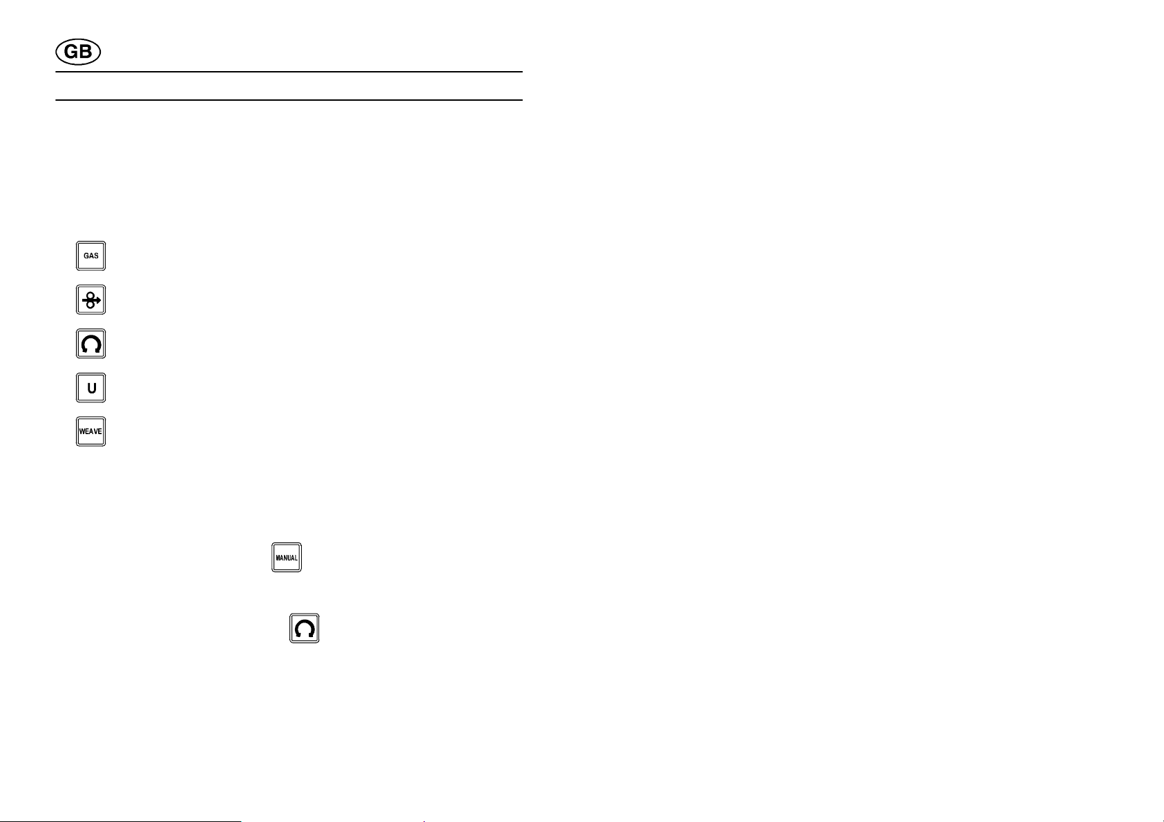
The welding parameters are divided into seven different groups, each group
represented by one ordinary key and a set of soft keys.
Welding current Gas
Rotation speed Wire feed speed
Arc voltage control (AVC) Weaving
Preheating time
dpa8d1ea
-- 8 --

SHIFT key
This key is used for changing the significance of other keys on the
keyboard.
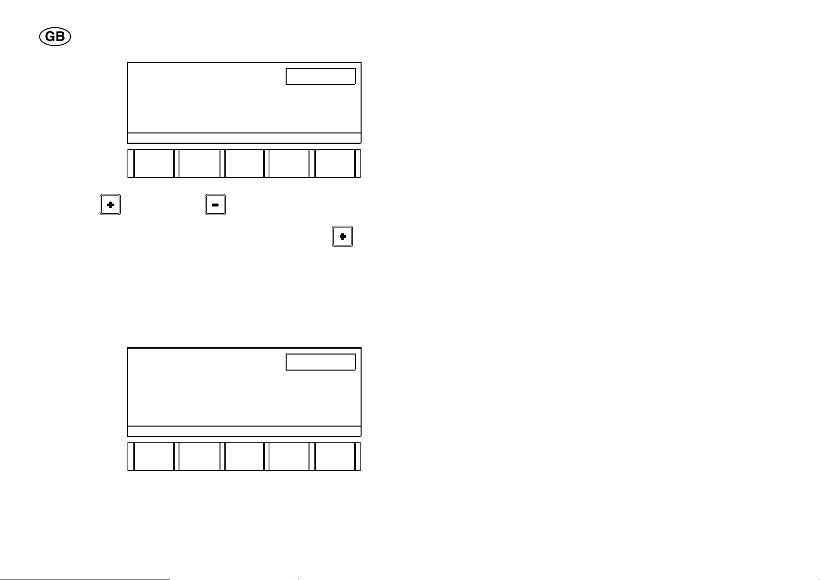
PLUS/MINUS keys
These keys are used for increasing/decreasing set values.
Numerical keys
These keys are used for entering the digits 0--9 and decimal point.
Other keys
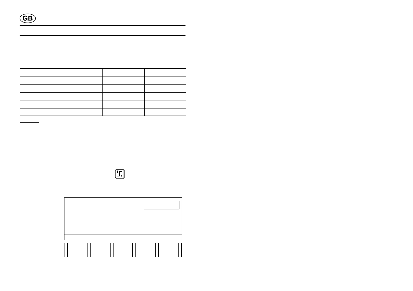
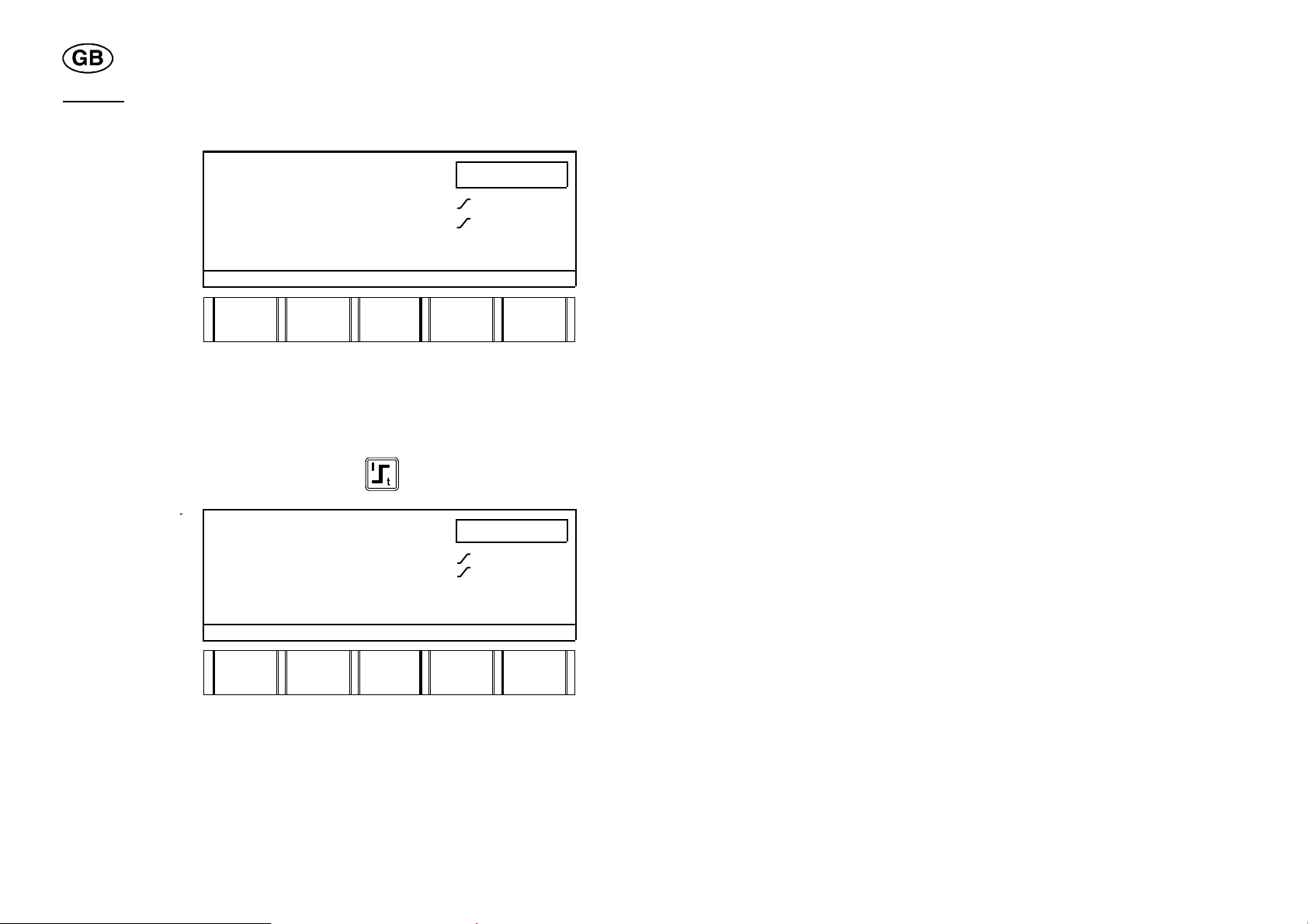
SLOPE
This key is used when you want to add a slope function to a parameter and
is indicated in the following way in the display
.
By slope is meant a gradual change of a set value.
Slope up = gradual increase
Slope down = gradual decrease
The following parameters can be assigned a slope function:
dpa8d1ea
-- 9 --

Current (both peak and background current) when pulsed current is used,
rotation, arc length control, wire feed speed , weaving amplitude.
A slope can be time--controlled by indicating that it shall go on for a certain
number of seconds. It can also be sector--controlled, making it a so--called
sector slope, by indicating between which two breakpoints it shall be
located.
SECTOR
This key indicates the breakpoint of a program and moving to indicated
sector.
STEP
This key is used for stepping forward in the program.
DELETE
This key is used for deleting the whole program, part of a program in the
working area, or just the figures in the digit box.
MANUAL MODE
This key is used for positioning the electrode before welding, and for making
sure that the program in the working area functions as desired.
MEMORY (library)
This key is used for entering or leaving the library and for storing a program,
or for recalling a program from the library to the working area.
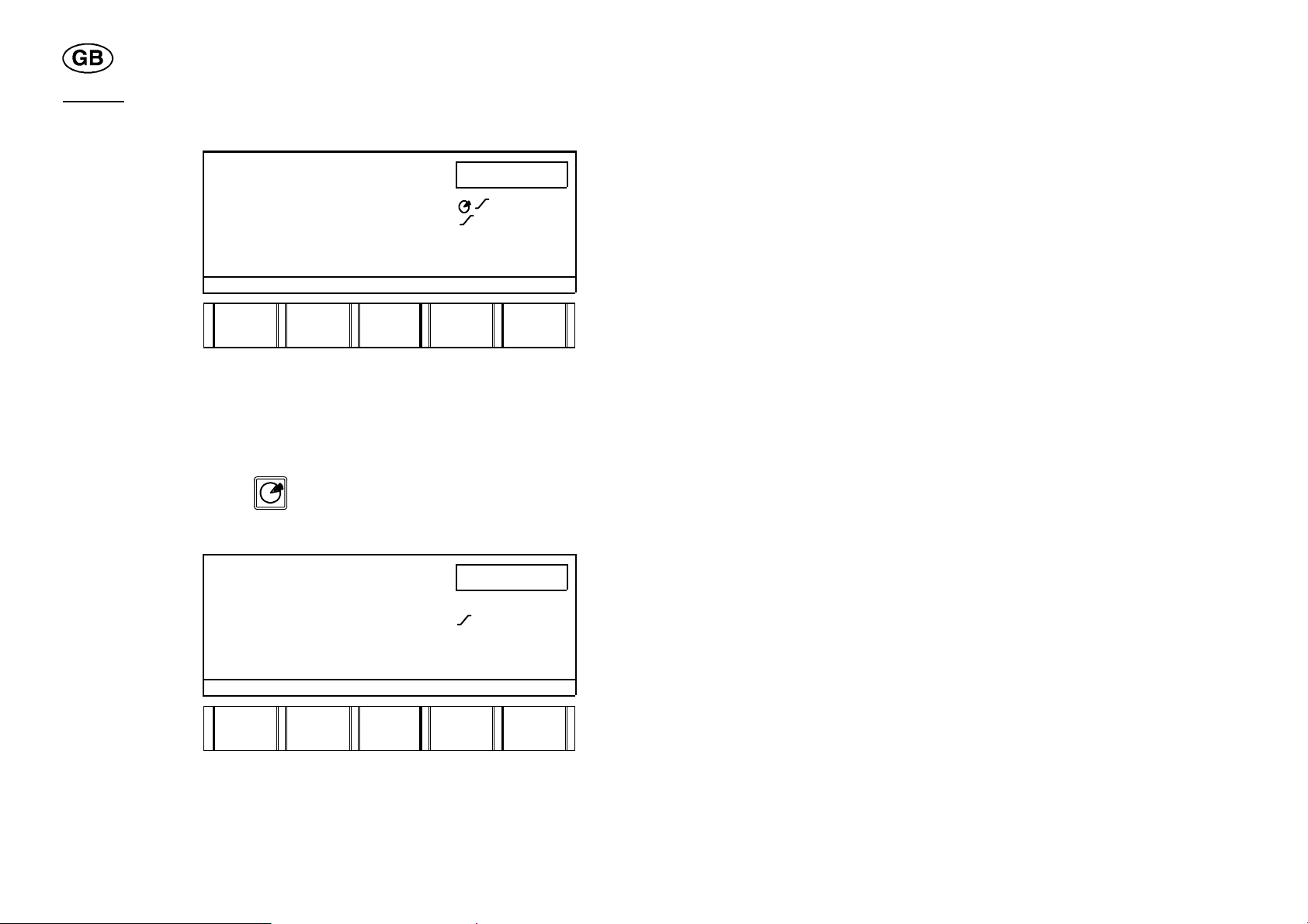
CORRECT
This key is used for correcting the position of the electrode in connection
with weaving (centre line adjustment).
MODE (auxiliary functions)
This key is used for getting to the different auxiliary functions, such as
language, error log, show actual parameter values and software upgrading.
NEXT
This key is not used.
dpa8d1ea
-- 1 0 --

NOTEBOOK
These keys are used if you want to make notes on a welding sequence.
TOOL CODE
These keys are used if you want to view the code of the connected tool.
RESTART
These keys are used for restarting a welding sequence.
SECTOR SLOPE
These keys are used if you want to create a sector slope.
DIRECT STOP
Pressing this key will lead to direct stop of the welding. The gas postflow
takes place according to settings in the end sector.
START
This key is used for starting a welding sequence.
STOP
This key is used for stopping a welding sequence. The welding sequence is
terminated according to the settings in the end sector.
dpa8d1ea
-- 1 1 --

2 WELDING PARAMETERS
Setting ranges for the welding parameters can be found in the APPENDIX
on page 102.
2.1 Welding current
There are four different parameters for welding current:
S PEAK CURRENT
S BACKGROUND CURRENT
S PEAK TIME (1 s)
S BACKGROUND TIME (1 s)
The values in brackets are preset values.
Peak time
Background time
current
Peak
Background current
The welding current can be either pulsed or continuous (not pulsed).
If you want to weld using pulse current a value must be entered for all four
parameters. When welding with continuous current, however, you only need
to enter the value for peak current. Entering a value also for background
current will result in pulsed current with preset pulse and background
times. Of course, the pulse and background times can also be changed.
The weaving motion can be synchronised with the welding current (pulsed
current) so that the peak current sets in at the same time as the electrode is
in an end position. This is also called special pulsing.
dpa8d1ea
-- 1 2 --

Special pulsing
By special pulsing is meant that the welding current is synchronised with the
weaving motion, i.e. you get peak current when the electrode is in an end
position of the weaving motion. Thus the peak current time is determined by
the dwell time of the respective dwell position.
Special pulsing can be used in combination with both continuous and pulsed
rotation. Special pulsing with pulsed rotation -- also called square--wave
pulsing -- means that the gear ring rotates when the electrode is in an end
position of the weaving motion.
Special pulsing with
continuous rotation
Rotation direction
Special pulsing with
pulsed rotation
Rotation direction
A = background current B = peak current
As to special pulsing, the wire feed can be either continuous or pulsed. As
to pulsed wire feed, the synchronisation with the welding current takes place
in the way described above, see the section “Wire Feed Speed“ on page 15.
dpa8d1ea
-- 1 3 --

SECTOR 1(4)
PEAK CURRENT
BACKGR. CURRENT
PEAK TIME
BACKGR. TIME
0.000
A
A
s
s
CONT/
PEAK
CURR
BACKGR
CURR
PEAK
TIME
BACKGR
TIME
SPEC.
PULS
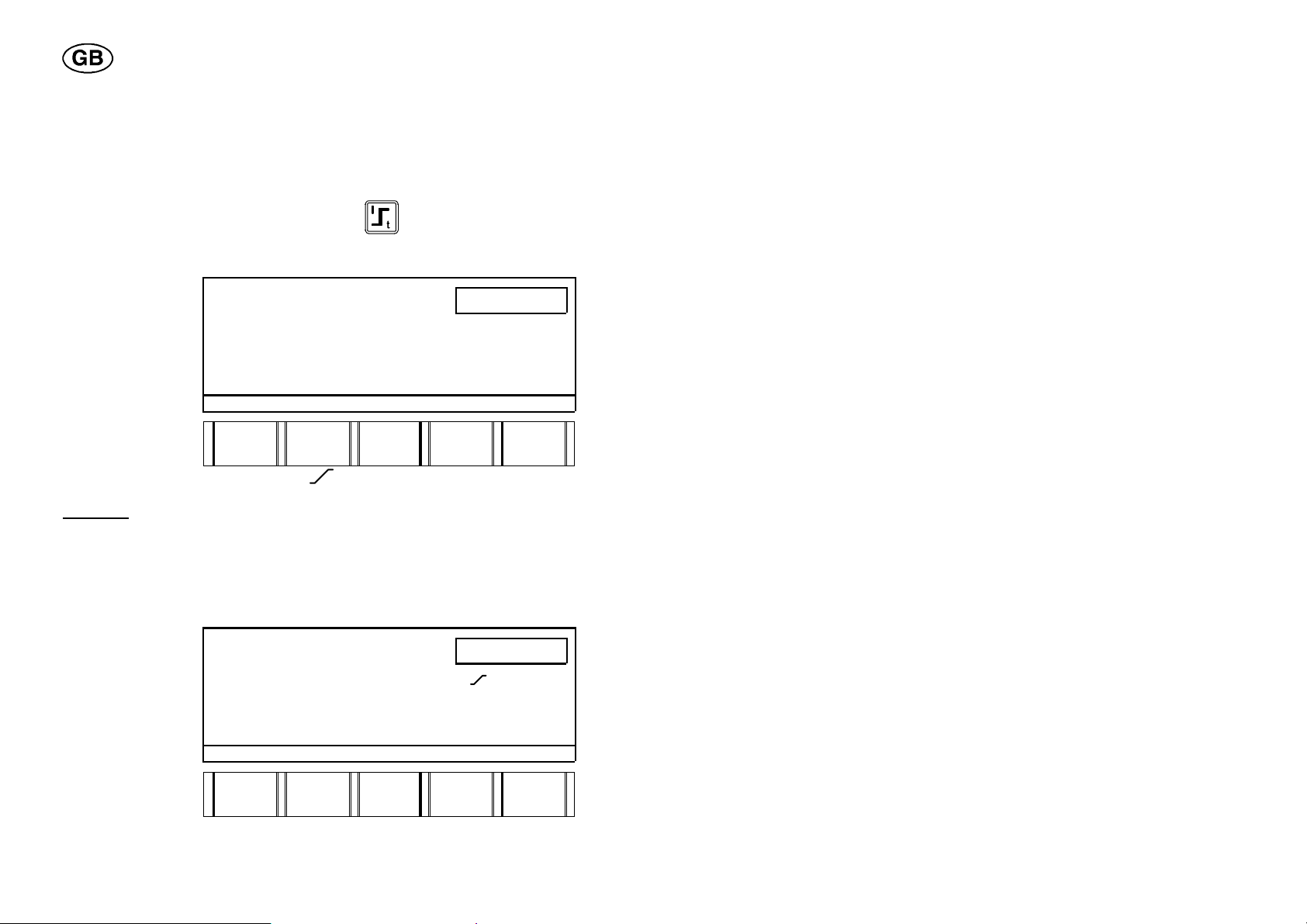
To activate the function special pulsing, press the marked soft key in the
display for welding parameters.
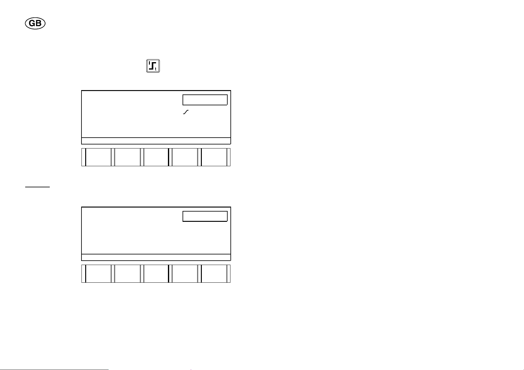
2.2 Gas
In the Shielding Gas parameter group three parameters are represented:
S WELD GAS
S ROOT GAS
S START GAS
By weld gas is meant the shielding gas on the upper side of the joint. The
weld gas parameter indicates the time the shielding gas is to flow on the
upper side of the joint before and after welding.
The values of the weld gas parameter are preset. The following values for
preflow and postflow of the weld gas apply at the start if nothing else has
been indicated:
S Weld gas preflow = 2 s
S Weld gas postflow = 4 s
By root gas is meant the shielding gas on the underside of the joint. The
root gas parameter indicates the time the shielding gas is to flow on the
underside of the joint before and after welding.
dpa8d1ea
-- 1 4 --

Some shielding gases, for example helium (He), can cause difficulty with
regard to striking the arc. If such a shielding gas is to be used as weld gas,
it could be advisable to use another gas mixture at the start moment -- a
so--called start gas.
If one value is entered for weld gas in sector 1 and one for start gas, only
the start gas is going to flow. The weld gas starts flowing when the arc is
struck.
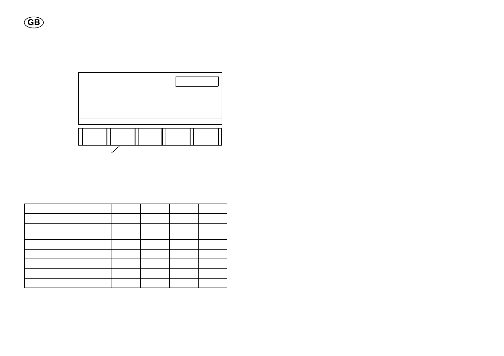
2.3 Wire feed speed
This parameter is used to indicate the desired feed speed of the filler wire in
cm/min.
The wire feed speed can be pulsed or continuous (not pulsed).
In the Wire Feed Speed parameter group two parameters are represented:
S PEAK WIRE FEED SPEED
S BACKGROUND WIRE FEED SPEED
For welding with continuous (not pulsed) wire feed speed, only the peak
wire feed parameter shall be entered.
For welding with pulsed wire feed speed, both the peak wire feed speed
and the background wire feed speed parameters shall be entered.
The pulsed wire feed speed is always automatically synchronised with the
welding current. The wire feed speed is high using pulse current and low
using background current.
2.4 Preheating t ime
Preheating is used for heating the workpiece at the starting point in order to
obtain correct penetration of the molten pool. The preheating time is defined
as the time elapsing between arc strike and start of the rotary motion. If no
value has been entered for the preheating parameter, the arc will strike at
the same time as rotation is started.
NOTE! In the Welding Current parameter group you cannot indicate a
sector slope when preheating is involved.
dpa8d1ea
-- 1 5 --

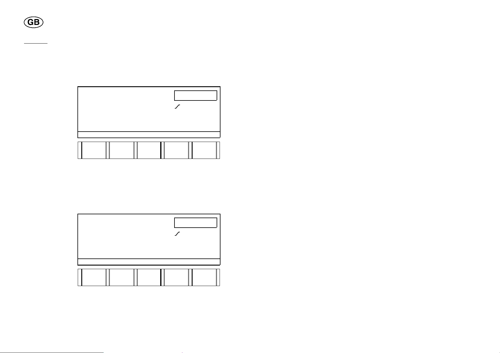
2.5 Rotation speed
This parameter indicates the rotation speed of the electrode round the
workpiece. It is indicated in per mill (thousandths) of the max. rotation speed
of the welding tool used.
Just like welding current and wire feed speed, the rotation speed can be
pulsed or continuous (not pulsed).
In the Rotation Speed parameter group four parameters are represented:
S ROTATION FORWARDS
S ROTATION BACKWARDS
S PULSED ROTATION FORWARDS
S PULSED ROTATION BACKWARDS
The pulse rotation is always automatically synchronised with the welding
current. The welding tool rotates when peak current is used, and stands still
when background current is used.
2.6 Arc voltage control (AVC)
This parameter is used for automatic control of the arc when welding with a
tool fitted with an AVC unit.
Arc voltage control (AVC) means that the arc voltage, and by that the length
of the arc (i.e. the distance between the tip of the electrode and the
workpiece), is automatically controlled in the course of welding.
In the Arc Voltage Control (AVC) parameter group three parameters are
represented:
S PEAK VOLTAGE (Arc voltage when using peak current)
S BACKGROUND VOLTAGE (Arc voltage when using background
current)
S DELA Y TIME
dpa8d1ea
-- 1 6 --

With the parameters peak voltage and background voltage you set the
reference value for arc voltage control when using peak current and
background current. When using continuous current only the peak voltage
parameter shall be entered.
If no value is entered for peak voltage a value measured right after the
welding start is used as reference value.
If no value is entered for background voltage and pulsed welding current
has been selected, no arc voltage control takes place when background
current is used.
NOTE! A time slope cannot be indicated in sector 1 for peak voltage and
background voltage.
In order to stabilise the arc before starting the arc voltage control, a delay
time can be entered. During the delay time the AVC unit is locked.
If no delay time is entered the following applies:
S The delay time will be equally long (at least 5 seconds) as the slope--up
time (if any) for the welding current.
If the slope--up time is shorter than 5 seconds, the AVC unit can start
controlling when the slope time has elapsed, but only by increasing the
arc voltage (arc length).
S If no slope--up time has been entered for the welding current, a fixed
delay time of 5 seconds applies. The AVC unit is not completely locked -the arc voltage (arc length) can be increased.
dpa8d1ea
-- 1 7 --

2.7 Weaving
Weaving is used if you want to oscillate the electrode laterally when welding
with welding tools fitted with a weaving unit.
In the Weaving parameter group four parameters are represented:
S WEAVE AMPLITUDE (5 mm)
S WEAVE SPEED (5 mm/s)
S DWELL TIME RIGHT (1 s)
S DWELL TIME LEFT (1 s)
amplitude (mm)
left
dwell time (s)
right
dwell time (s)
Weave speed (mm/s)
The values in brackets are preset values. If one of the parameter values is
indicated in the display, the preset values will come up automatically.
The weaving motion can be synchronised with the welding current (pulse
current) so that the pulse current sets in at the same time as the electrode is
in dwell position. This is also called special pulsing and is described in the
section Special Pulsing on page 13.
dpa8d1ea
-- 1 8 --
3 START AND STOP
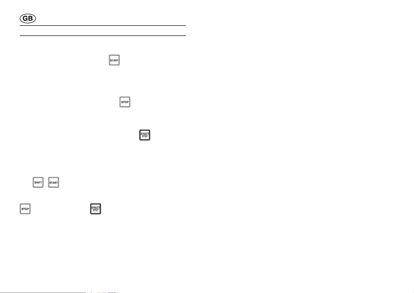
3.1 Start
To start the welding, use the START key .
It is impossible to start a welding program if another tool code has been
indicated than the one used in the program in question.
3.2 Stop
A requested welding stop over the STOP key means that the program
jumps to the following end sector, no matter which sector you are in at the
moment. The welding is terminated according to the settings of the end
sector.
A requested welding stop over the DIRECT STOP key
immediate stop of the welding. The gas postflow takes place according to
the time set in the end sector.
leads to
3.3 Restart
If the welding was interrupted it is restarted with the SHIFT and START
keys
Irrespective of whether the welding was stopped over the STOP
or the DIRECT STOP key , the start parameters of the preceding
start sector are used. The program then continues from the position in the
welding program where it was interrupted.
dpa8d1ea
.
-- 1 9 --

4 TO GET STARTED
4.1 General
Some of the factors controlling the welding process are specific to each one
of the welding tools, for example the rotation speed. Therefore, every
welding program must be connected to a tool code, associated with the
tool that the program was made up for.
4.2 How to indicate a tool code
S Turn the mains switch on the welding power source to position 1.
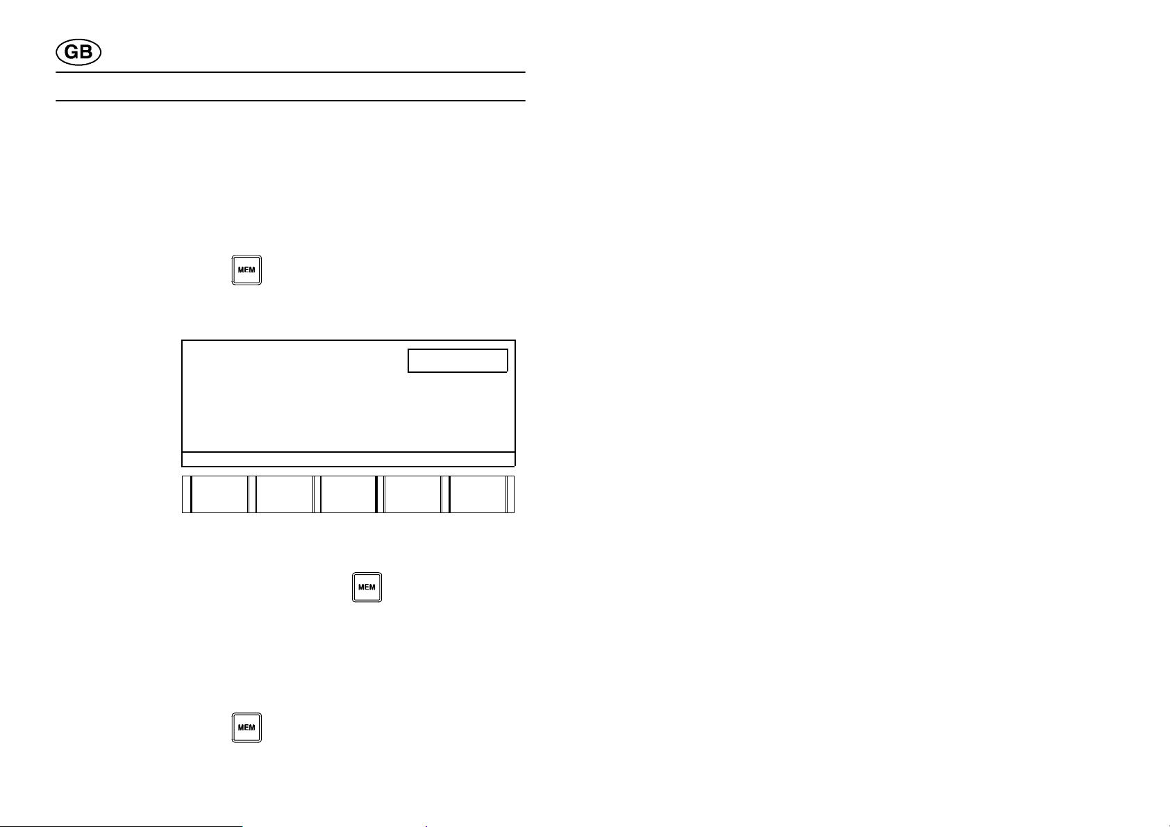
S The following display comes up:
CHOOSE CONNECTED TOOL
PRB , PRC "
PRH
PRD
POC 12--60 mm
TIG HAND TORCH
A25
NEXT
ENTER
Example: You have connected PRC 33--90
S Move the marking to the line for PRB, PRC using the soft key NEXT.
Choose the desired tool and press ENTER.
A window comes up, showing available tool sizes.
S Move the marking to the size of the tool you have connected (in this
example 33--90 mm) using the soft key NEXT and press ENTER.
dpa8d1ea
-- 2 0 --

CHOOSE CONNECTED TOOL
Pressthesof
t
g
p
existingpro
g
TOOLTYPEMISMATC
H
gra
m
PRB, PRC " 8--17 mm
PRH 17-- 49 mm
PRD 33-- 90 mm
POC 12--60 mm 60--170 mm
TIG HAND TORCH
A25
NEXT
QUIT ENTER
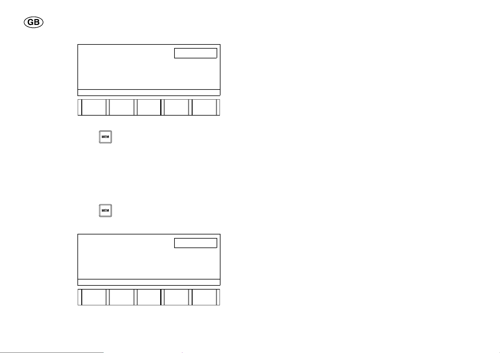
Result: The new tool code is accepted and the following text is displayed:
CONNECTED TOOL: PRB, PRC 33--90 mm.
NOTE! In the event a program with another tool code should already be
stored in the working area this must first be deleted. (If you want to keep the
old program that was stored in the working area, you must store it in the
library.)
The following information is displayed in the display:
S
key delete
existin
ram.
.
ro-
WARNING!
TOOLTYPE MISMATCH
PROGRAM MADE FOR: PRB, PRC 17-- 49 mm
CONNECTED TOOL: PRB, PRC 33-- 90 mm
DELETE
PROG.
Result: The new tool code is accepted and the display displays:
CONNECTED TOOL: PRB, PRC 33--90 mm.
dpa8d1ea
-- 2 1 --
4.3 How to change languages
Pressthesof
t
Pressthesof
t
l
The different texts displayed on the control box are available in the following
four languages:
S English, German, Swedish, Norwegian.
On delivery and after resetting the box, all texts displayed are in English.
Language
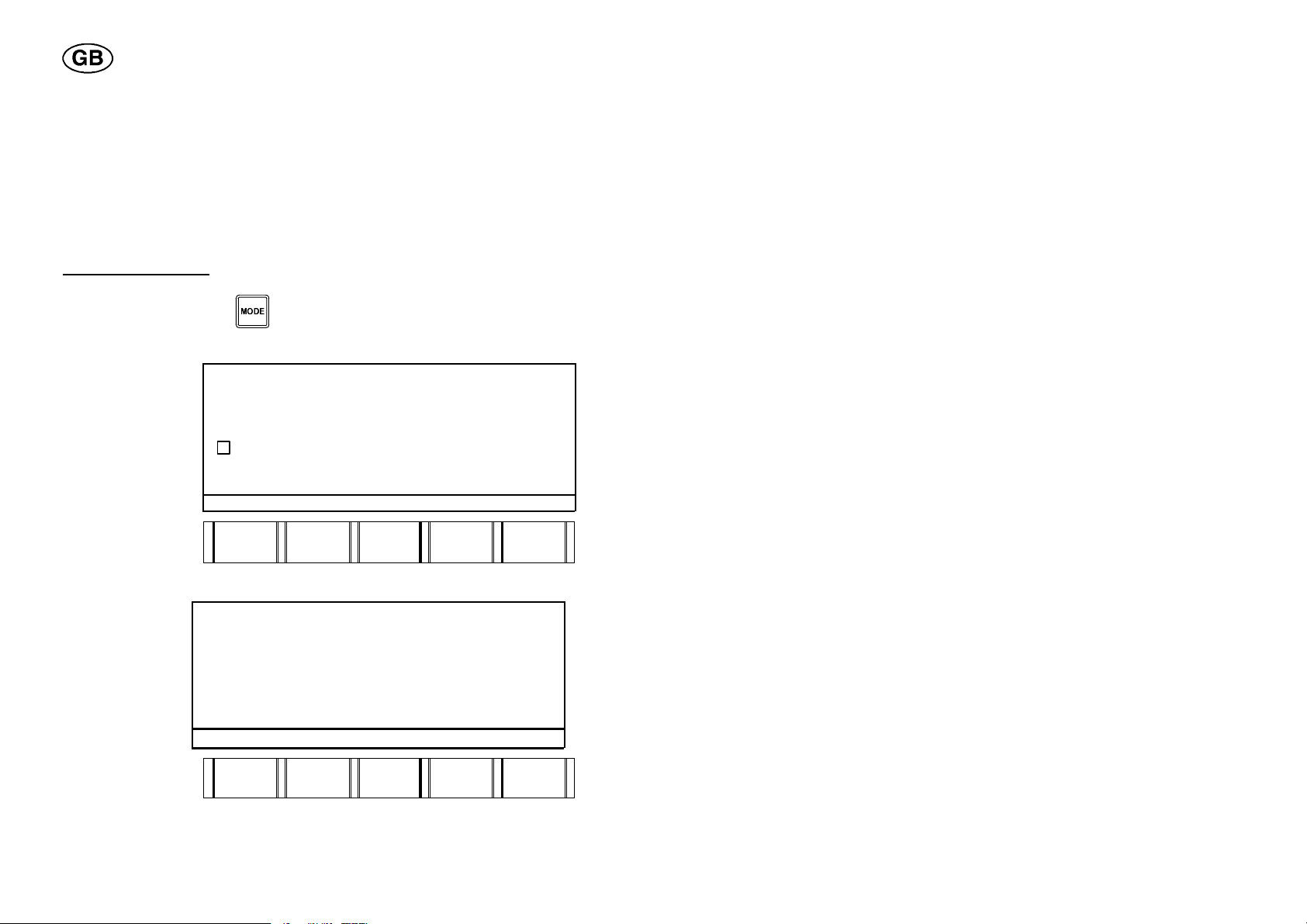
S Press the MODE key
selection
to get to the auxiliary functions, and the
following display comes up:
S
key language.
LANGUAGE "
ERROR LOG "
SHOW ACTUAL PARAMETER VALUES
SOFTWARE UPGRADE "
SOFTWARE KEY "
LAN-GUAGE
AUXILIARY FUNCTIONS
ERROR
LOG
SHOW
PARA- METER
SOFT--.
WARE
UPGR.
SOFT-WARE
KEY
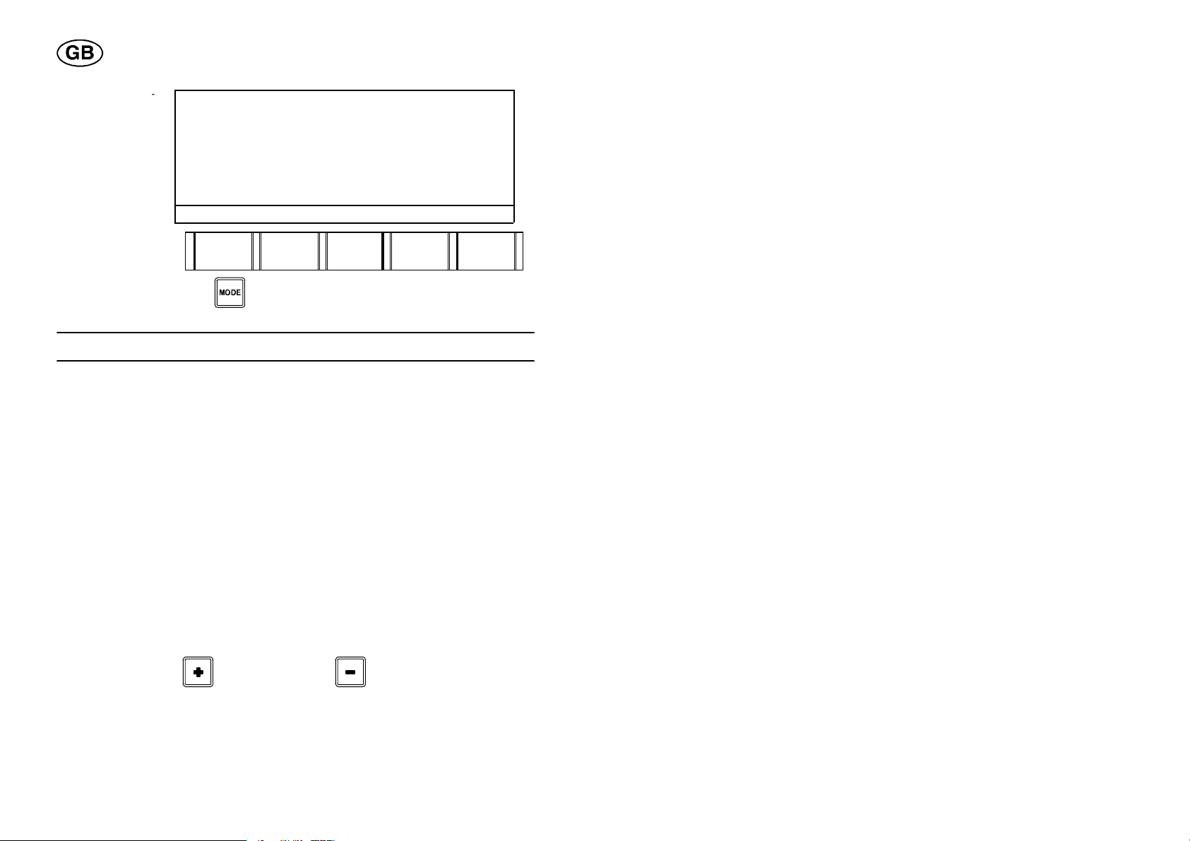
S Press the soft key next language and step to the desired language.
S
key change
CHOSEN LANGUAGE: ENGLISH
anguage.
AVAILABLE LANGUAGES
ENGLISH NORSK
DEUTSCH
SVENSKA
NEXT
LANG
CHANGE
LANG
QUIT
Result: All texts will from now on be in the new language (in this example
Swedish).
dpa8d1ea
-- 2 2 --
S
Terminate
byy
ftk
pressing the
so
bryt.
ey av-
VALT SPRÅK: SVENSKA
TILLGÄNGLIGA SPRÅK
ENGLISH NORSK
DEUTSCH
SVENSKA
NÄSTA
SPRÅK
BYT
SPRÅK
AVBRYT
S Press the MODE key to return to the working area.
5 PROGRAM EDITING
5.1 Entering a parameter value
S Make sure the right group of parameters is displayed in the display by
pressing one of the seven parameter keys.
S Enter a value in the digit box.
S Press the soft key of the desired parameter.
Note that the parameters always inherit the value from the previous
sector if no new value is entered.
5.2 Increasing/decreasing a parameter value
The parameter value to be altered must be shown in the digit box.
S Mark the desired parameter using one of the soft keys. The set value
comes up in the box.
S Press the PLUS
dpa8d1ea
or the MINUS key .
-- 2 3 --

5.3 Creating a new sector
A new sector is created by entering a new breakpoint into an existing sector.
S Enter a new value for the breakpoint of the new sector.
S Press the SECTOR key
In doing this, a new sector is created which is a copy of the original sector,
but with another breakpoint and another sector number. The new sector is
automatically positioned in the right place in the program. This is determined
by the value of the new breakpoint.
Creating a new sector during welding
Proceed as follows to create a new sector during the welding:
S Enter a value into one of the following parameter groups using the
numerical keys:
S Press the corresponding soft key.
A new sector is now automatically created.
.
5.4 Changing the breakpoint of a sector
Make sure the existing breakpoint value of the sector is displayed in the digit
box.
S Press the SECTOR key
The breakpoint value is now shown in the digit box.
S Enter the new breakpoint value.
.
S Press the SECTOR key
or
S Change the breakpoint value using the PLUS key
key
dpa8d1ea
.
-- 2 4 --
or the MINUS

5.5 Creating a transport secto r
If you want to rotate the welding tool without welding within a sector, you
can create a transport sector. Sector 1 cannot function as a transport
sector -- it can only function as a delayed start.
Transport sector
S Enter a value for the breakpoint of the new sector using the numerical
keys.
S Press the SECTOR key
S Set the WELDING CURRENT
.
(the peak current) to 0.
NOTE! If the welding current value is inherited, the welding current value of
the following sector will also be 0. Don’t forget to change them to the right
value.
All the other parameter values can remain.
Delayed start
Change the breakpoint of sector 1 in the following way in order to delay the
start:
S Press the STEP key
S Press the SECTOR key
and go to sector 1.
.
S Enter the breakpoint, for example 0.100 instead of 0.000, using the
numerical keys.
S Press the SECTOR key
again.
dpa8d1ea
-- 2 5 --

5.6 Finding the home position
When the tube welding tools PRH and POC are used, it can sometimes be
necessary to return to the home position (start position), for example in the
event of a welding stop.
S Rotate the tool manually till it is within a tenth of a rotation to the left or
right of the home position. See also under the section “Manual Mode” on
page 56.
S Press the START key
Once this is done, the welding tool automatically starts rotating to the home
position, and a welding sequence starts.
.
5.7 Entering a slope
A time slope or a sector slope can be indicated for the following parameter
groups:
Welding current Rotation speed
Arc voltage control (AVC) Weaving
Wire feed speed
Time slope
S Press the key for the parameter group in question.
S Mark the desired parameter using one of the soft keys.
S Enter the desired slope time value.
S Press the SLOPE key
dpa8d1ea
.
-- 2 6 --

Sector slope
To create a sector slope no time value is to be entered. A sector slope
always goes on from one breakpoint to the next one.
NOTE! In the Welding Current parameter group you cannot indicate a
sector slope when preheating is involved.
S Press the key for the parameter group in question.
S Mark the desired parameter using one of the soft keys.
S Press the SHIFT key
and the SLOPE key simultaneously,
and a sector slope is created.
Whatisaslope?
A slope is a linear change between two parameter values, based on time or
position (breakpoint).
A time--based slope (time slope) is active during the time indicated.
A position--based slope (sector slope) is active between two adjacent
breakpoints.
5.8 Moving within a program
Move to the next parameter group
Using the STEP key
When using the STEP function, only the parameter groups that have been
assigned a value are displayed.
When stepping through the end sector, you will automatically jump to the
tool code.
Move between
sectors
By entering a sector number in the digit box in the display and then pressing
you can step through the whole welding program.
the SECTOR key
it is possible to jump between the different sectors of
the program. When jumping to a new sector you always end up in the same
group of parameters as the one you left.
dpa8d1ea
-- 2 7 --

5.9 Deleting in a program
Delete a parameter value
You can delete a parameter value if it has not been borrowed from a
previous sector. For the value to be deleted, it must be displayed in the digit
box.
S Press the DELETE key
. The digit box asks DEL?
S Press the soft key of the parameter to confirm.
Delete a
sector
You can only delete the sector in which you are at the moment. It can be
done in two different ways:
Alternative 1
S Press the DELETE key
and then the SECTOR key .
Alternative 2
S Press the SECTOR key
. The breakpoint of the sector comes up in
the digit box.
S Press the DELETE key
S Press the SECTOR key
. The digit box asks DEL?
to confirm.
dpa8d1ea
-- 2 8 --

Delete the contents of the working area
The working area always contains the welding program last used. Maybe
you want to clear the working area completely, for example to change the
tool code.
Delete a program in the working area in the following way:
S Press the DELETE key
and then the MEMORY key .
5.10 Changing weld data during welding
To change welding data in the course of welding, a value must be displayed
in the digit box.
S Mark the parameter in question using one of the soft keys. The set value
now comes up in the digit box.
S Enter the new value using the numerical keys, or increase/decrease the
value using the PLUS
NOTE! When a value is changed in the working area, the old value will be
overwritten and the new one applies. If the value is inherited, the value in
the following sector will also be changed.
/ MINUS keys.
dpa8d1ea
-- 2 9 --

5.11 Zeroing the control box
In the event the control box should get blocked, i.e. it does not react when
the keys are activated, it is necessary to reset the box. This is done in the
following way:
S Set the mains voltage switch on the power source to 0.
S Hold down the mid one of the five soft keys on the control box, and turn
the mains voltage switch to position 1.
dpa8d1ea
-- 3 0 --
6 PROGRAMMING EXAMPLES
Pressthesof
t
ouspeak
6.1 Example 1a:
The first example is a simple welding program, consisting of two sectors,
sector 2 being a stop sector. The program contains four parameters:
welding current, rotation, weld gas preflow and weld gas postflow.
Sector 1 Sector 2
Breakpoint 0.000 1.010
Welding current (continuous) (A) 200 0
Rotation (continuous) (‰) 250 250
Gas preflow (weld gas) (s) 5
Gas postflow (weld gas) (s) 7
Sector 1
Breakpoint
Sector 1 automatically is assigned the breakpoint 0.000, if nothing else is
indicated.
Welding current
Pulse current = 200 A
S Press the key for WELDING CURRENT
. The picture for welding
current settings comes up in the display.
S Enter the value 200 using the numerical keys.
S
key continu-
pulse current.
SECTOR 1(1) 0.000
PEAK CURRENT A
BACKG. CURRENT A
PEAK TIME s
BACKGR.TIME s
CONT/
PEAK
CURR.
BACKGR.
CURR.
PEAK
TIME
200
BACKGR
TIME
SPEC.
PULS
Result: PEAK CURRENT = 200 A in sector 1.
dpa8d1eb
-- 3 1 --

Rotation speed
Pressthesof
t
forward
Pressthesof
t
Continuous rotation forward = 250 ‰ of the max. rotation speed.
S Press the key for ROTATION SPEED
.
S Enter the value 250 using the numerical keys.
S
key rotation
.
SECTOR 1(1) 0.000
ROTATION FORWARD
ROTATION BACKW.
PULSE ROT. FORW.
PULSE ROT. BACKW.
ROTA
TION
FORW
ROTA-TION
BACKW
PULSE
ROT.
FORW
250
PULSE
ROT.
BACKW.
Result: ROTATION FORWARD = 250 in sector 1.
Gas
Preflow of weld gas = 5sin sector 1.
S Press the key for gas
.
S Enter the value 5 using the numerical keys.
The gas preflow has a preset value of 2 s, which applies if no other value
is entered and displayed in the display at the start.
S
key weld gas.
SECTOR 1(1) 0.000
5
WELD GAS s
ROOT GAS s
START GAS s
WELD
GAS
ROOT
GAS
START-GAS
Result: WELD GAS = 5 s in sector 1.
dpa8d1eb
-- 3 2 --

Sector 2
Pressth
e
Pressthesof
t
ouspeak
Breakpoint
S Enter the value of the new breakpoint 1.010 using the numerical keys.
S
SECTOR key.
SECTOR 1(1) 0.000
1 WELD GAS 5 s
ROOT GAS s
START GAS s
1.010
WELD
GAS
ROOT
GAS
START
GAS
Result: Sector 2 out of 2 sectors in all.
Welding current
Peak current = 0A
As sector 2 is to be a stop sector, the welding current must be assigned the
value of 0 amperes. Note that the parameter (peak current) has been
assigned the value 200 as the value was inherited from the preceding
sector.
S Press the key for WELDING CURRENT
.
S Enter the value 0 using the numerical keys.
S
key continu-
current.
SECTOR 2(2) 1.010
1 PEAK CURRENT 200 A
BACKGR. CURRENT A
PEAK TIME s
BACKGR. TIME s
CONT/
PEAK
CURR.
BACKGR
CURR.
PEAK
TIME
0
BACKGR
TIME
SPEC.
PULS
Result: PEAK CURRENT = 0 A in sector 2 (end sector).
dpa8d1eb
-- 3 3 --

Rotation speed
Pressthesof
t
As this is the last sector of the program and the welding current is set to 0,
the sector will be interpreted as a stop sector, irrespective of the rotation
value. In other words, we can keep the rotation value that was borrowed
from the previous sector.
S Press the key for ROTATION SPEED
SECTOR 2(2) 1.010
1 ROTATION FORWARD 250
ROTATION BACKW.
PULSE ROT. FORW.
PULSE ROT. BACKW.
ROTA
TION
FORW.
ROTA-TION
BACKW.
to view the result.
PULSE
ROT.
FORW.
PULSE
ROT.
BACKW.
Result: ROTATION FORWARD = 250 ‰ in sector 2 (borrowed value)
Gas
The weld gas preflow of = 7s.
S Press the key for gas
.
S Enter the value 7 using the numerical keys. The gas postflow has a
preset value of 4 s, which applies if no other value is entered and
displayed in the display at the start.
S
key weld gas.
SECTOR 2(2) 1.010
7
1WELDGAS s
ROOT GAS s
START GAS s
WELD
GAS
ROOT
GAS
START
GAS
Result: WELD GAS = 7 s in sector 2.
dpa8d1eb
-- 3 4 --

6.2 Example 1b:
Pressth
e
We now want to extend the previous program by adding a slope up and
slope down time to the welding current. We also add a new sector to the
program, which is to be placed between the other two sectors.
Sector 1 Sector 2 Sector 3
Breakpoint 0.000 0.500 1.010
Welding current (continuous) (A) 200 150 0
Slope up (s) 2 -- -Slope down (s) -- -- 4
Rotation, continuous (‰) 250 250 250
Gas preflow (weld gas) (s) 5 -- -Gas postflow (weld gas) (s) -- -- 7
Sector 1
Go back to sector 1.
S Enter the value 1 using the numerical keys.
S
SECTOR key.
SECTOR 2(2) 1.010
1
2 WELD GAS 7 s
ROOT GAS s
START GAS s
WELD
GAS
ROOT
GAS
START
GAS
Result: Return to sector 1 with the breakpoint 0.000.
dpa8d1eb
-- 3 5 --
Slope
Enterth
eva
lue
Enterth
eva
lue
The slope--up time = 2sfor the peak current of sector 1.
When a slope function is to be added, first make sure the corresponding
picture is displayed in the display.
S Press the key for WELDING CURRENT
.
S Press the soft key for continuous peak current.
S
2.
S Press the
SLOPE key.
SECTOR 1(2) 0.000
1 PEAK CURRENT 200 A
BACKGR. CURRENT A
PEAK TIME s
BACKGR. TIME s
CONT/
PEAK
CURR.
BACKGR
CURR.
PEAK
TIME
2
BACKGR
TIME
SPEC.
PULS
Result: PEAK CURRENT = 200 A, 2.0 s in sector 1.
Sector
2
New breakpoint = 0.500
We are now going to add a sector to the program. The breakpoint of the
new sector is to be 0.500, and the sector will automatically be placed
between the two sectors already existing.
S
0.5.
S Press the
SECTOR key.
SECTOR 1(2) 0.000
1 PEAK CURRENT 200 A
BACKGR. CURRENT A
PEAK TIME s
BACKGR. TIME s
0.5
2.0 s
CONT/
PEAK
CURR.
BACKGR
CURR.
PEAK
TIME
BACKGR
TIME
SPEC.
PULS
Result: Breakpoint 0.500 is placed as sector no. 2 (borrowed value).
dpa8d1eb
-- 3 6 --
Welding current
Pressthesof
t
ouspeak
Enterth
eva
lue
numericalkeys
Peak current = 150 A
S Press the key for WELDING CURRENT
S Enter the value 150 using the numerical keys.
S
key continu-
current.
SECTOR 2(3) 0.500
1 PEAK CURRENT 200 A
BACKGR CURRENT A
PEAK TIME s
BACKGR. TIME s
CONT/
PEAK
CURR.
BACKGR
CURR.
PEAK
TIME
Result: PEAK CURRENT = 150 A in sector 2.
Sector
3
Go to sector 3.
S
3 using the
SECTOR 2(3) 0.500
.
S Press the
SECTOR key.
2 PEAK CURRENT 150 A
BACKGR. CURRENT A
PEAK TIME s
BACKGR. TIME s
.
150
2.0 s
BACKGR
TIME
SPEC.
PULS
3
CONT/
PEAK
CURR
BACKGR
CURR.
PEAK
TIME
BACKGR
TIME
SPEC.
PULS
Result: You have moved to sector 3 with the breakpoint 1.010.
dpa8d1eb
-- 3 7 --
Slope
Enterth
eva
lue
Slope down = 4sfor the peak current of sector 3.
S Press the soft key for continuous peak current.
S
4.
S Press the
SLOPE key.
SECTOR 3(3) 1.010
3 PEAK CURRENT 0 A
BACKGR CURRENT A
PEAK TIME s
BACKGR. TIME s
4
CONT/
PEAK
CURR.
BACKGR
CURR.
PEAK
TIME
BACKGR
TIME
SPEC.
PULS
Result: PEAK CURRENT = 0 A, 4.0 s in sector 3 (stop sector).
6.3 Example 1c:
We now extend the previous program by changing the welding current of
sector 1 from 200 A to 180 A. We also add a new sector to the program,
which will automatically be placed between sector 1 and sector 2.
Sector 1 Sector 2 Sector 3 Sector 4
Breakpoint 0.000 0.250 0.500 1.010
Welding current (continuous)
(A)
Slope up (s) 2 -- -- -Slope down (s) -- 4 -- 4
Rotation, continuous (‰) 250 250 250 250
Gas preflow (weld gas) (s) 5 -- -- -Gas postflow (weld gas) (s) -- -- -- 7
180 170 150 0
dpa8d1eb
-- 3 8 --

Sector 1
Enterth
eva
lue
numericalkeys
Pressthesof
t
ouspeak
Go back to sector 1.
S
1 using the
.
S Press the
SECTOR key.
SECTOR 3(3) 1.010
3 PEAK CURRENT 0 A
BACKGR CURRENT A
PEAK TIME s
BACKGR. TIME s
1
4.0 s
CONT/
PEAK
CURR.
BACKGR
CURR.
PEAK
TIME
BACKGR
TIME
Result: Return to sector 1 with the breakpoint 0.000.
Welding current
Peak current = changed from 200 A to 180 A.
S Enter the value 180 using the numerical keys.
S
key continu-
current.
SECTOR 1(3) 0.000
1 PEAK CURRENT 200 A
BACKGR CURRENT A
PEAK TIME s
BACKGR. TIME s
CONT/
PEAK
CURR.
BACKGR
CURR.
PEAK
TIME
BACKGR
TIME
Result: PEAK CURRENT = 180 A, 2.0 s in sector 1.
180
2.0 s
SPEC.
PULS
SPEC.
PULS
dpa8d1eb
-- 3 9 --
Sector 2
Enterth
eva
lue
Pressthesof
t
ouspeak
New breakpoint = 0.250
We are now going to add a sector to the program. The new sector is to have
the breakpoint 0.250 and will automatically be placed in the right position
between sector 1 and sector 2.
S
0.25.
S Press the
SECTOR key.
SECTOR 1(3) 0.000
1 PEAK CURRENT 180 A
BACKGR. CURRENT A
PEAK TIME s
BACKGR. TIME s
0.25
2.0 s
CONT/
PEAK
CURR.
BACKGR
CURR.
PEAK
TIME
BACKGR
TIME
SPEC.
PULS
Result: SECTOR 0.250 is placed as sector 2 in the program (values
borrowed from sector 1).
Welding current
Peak current = 170 A.
S Enter the value 170 using the numerical keys.
S
key continu-
current.
SECTOR 2(4) 0.250
1 PEAK CURRENT 180 A
BACKGR. CURRENT A
PEAK TIME s
BACKGR. TIME s
CONT/
PEAK
CURR.
BACKGR
CURR.
PEAK
TIME
170
BACKGR
TIME
2.0 s
SPEC.
PULS
Result: PEAK CURRENT = 170 A in sector 2.
dpa8d1eb
-- 4 0 --

Slope
Enterth
eva
lue
numericalkeys
Slope down = 4sfor the peak current in sector 2.
S Press the soft key for continuous peak current .
S
4 using the
SECTOR 2(4) 0.250
.
2 PEAK CURRENT 170 A
S Press the
SLOPE key.
BACKGR. CURRENT A
PEAK TIME s
BACKGR. TIME s
4
CONT/
PEAK
CURR.
BACKGR
CURR.
PEAK
TIME
BACKGR
TIME
Result: PEAK CURRENT = 170 A, 4.0 s in sector 2.
SPEC
PULS
dpa8d1eb
-- 4 1 --

6.4 Example 1d:
We now extend the program further by adding some new welding
parameters.
Sector 1 Sector 2 Sector 3 Sector 4
Breakpoint 0.000 0.250 0.500 1.010
Welding current (continuous)
(A)
Welding current (background current) (A)
Welding current (pulse time)
(s)
Welding current (Background time) (s)
Slope up (s) 2 -- -- -Slope down (s) -- 3 -- 4
Preheating (s) 2 2 2 2
Rotation, (cont. forward) (‰) 250 250 250 250
Gas preflow (weld gas) (s) 5 -- -- -Gas postflow (weld gas) (s) -- -- -- 7
Wire feed (continuous)
(cm/min)
A VC, (pulse voltage) (V) 11.2 11.2 11.2 11.2
AVC,
(background voltage) (V)
Weaving, (weaving ampl.)
(mm)
Weaving, (weaving speed)
(mm/s)
Weaving, (dwell time right)
(s)
Weaving, (dwell time left) (s) 1.0 1.0 1.0 1.0
180 170 150 0
100 100 100 100
0.5 0.5 0.5 0.5
1.0 1.0 1.0 1.0
110 110 110 110
10.9 10.9 10.9 10.9
5.0 5.0 5.0 5.0
8.0 8.0 8.0 8.0
1.0 1.0 1.0 1.0
dpa8d1eb
-- 4 2 --

Sector 1
Enterth
eva
lue
numericalkeys
Pressthesof
t
groundcur
Go back to sector 1.
S
1 using the
.
S Press the
SECTOR key.
SECTOR 2(4) 0.250
2 PEAK CURRENT 170 A
BACKGR CURRENT A
PEAK TIME s
BACKGR TIME s
1
4.0 s
CONT/
PEAK
CURR.
BACKGR
CURR.
PEAK
TIME
BACKGR
TIME
SPEC.
PULS
Result: Return to sector 1 with the breakpoint 0.000.
Welding current
Background current = 100 A.
S Press the key for WELDING CURRENT
.
S Enter the value 100 using the numerical keys.
S
key back--
rent.
-
-
SECTOR 1(4) 0.000
1 PEAK CURRENT 180 A
BACKGR. CURRENT A
PEAK TIME s
BACKGR. TIME s
CONT/
PEAK
CURR
BACKGR
CURR.
PEAK
TIME
100
BACKGR
TIME
2.0 s
SPEC.
PULS
Result: BACKGR. CURRENT = 100 A. 2.0 s in sector 1 and
PULSE TIME = 1.00 s and BACKGR. TIME = 1.00 s (preset values)
dpa8d1eb
-- 4 3 --

Pulse time = 0.5 s instead of 1.0.
Pressthesof
t
Pressthesof
t
S Enter the value 0.5 using the numerical keys.
S
key peak time.
SECTOR 1(4) 0.000
0.5
1 PEAK CURRENT 180 A
BACKGR. CURRENT 100 A
PEAK TIME 1.00 s
BACKGR.TIME 1.00 s
CONT/
PULSE
CURR.
BACKGR
CURR.
PEAK
TIME
BACKGR
TIME
Result: PEAK TIME = 0.50 s instead of 1.00 s in sector 1.
Preheating time
The preheating time = 2s
S Press the key for PREHEATING TIME
.
S Enter the value 2.0 using the numerical keys.
S
key preheat.
SECTOR 1(4) 0.000
PREHEAT s
2,0
2.0 s
2.0 s
SPEC.
PULS
PRE-HEAT.
Result: PREHEAT = 2.0 in sector 1.
dpa8d1eb
-- 4 4 --

Wire feed speed
Pressthesof
t
ouspeakwire
Pressthesof
t
ous/pea
k
We are now going to use filler wire. As we intend to weld using continuous
wire feed (not pulsed) only the pulsed wire parameter need to be entered.
Pulsed wire = 110 cm/min
S Press the key for WIRE FEED SPEED
.
S Enter the value 110 using the numerical keys
S
key continu-
feed.
SECTOR 1(4) 0.000
PEAK WIRE. cm/m in
BACKGR WIRE. cm/min
CONT/
PEAK
WIRE
BACKGR
WIRE
Result: PEAK WIRE FEED = 110 cm/min in sector 1.
Arc voltage control (AVC)
The peak voltage = 11.2 V
S Press the key for ARC VOLTAGE CONTROL, (AVC)
S Enter the value 11.2 using the numerical keys.
S
key continu-
voltage.
SECTOR 1(4 ) 0.000
PEAK VOLTAGE V
BACKGR. VOLTAGE V
DELAY TIME s
110
.
11.2
CONT/
PULSE
VOLT.
BACKGR
VOLT.
DELAY
TIME
Result: PEAK VOLTAGE = 11.2 V in sector 1.
dpa8d1eb
-- 4 5 --

Background voltage = 10.9 V
Pressthesof
t
groundvol
t
Pressthesof
t
speed
S Enter the value 10.9 using the numerical keys.
S
key back-
age.
-
-
SECTOR 1(4 ) 0.000
1 PEAK VOLTAGE 11,2 V
BACKGR. VOLTAGE V
DELAY TIME s
10.9
CONT/
PULSE
VOLT.
BACKGR
VOLT.
DELAY.
TIME
Result: BACKGR VOLTAGE = 10.9 V in sector 1.
Weaving
We are now going to add values for weaving. Some of the values are
preset. See preset values, page 18 .
Weaving speed = 8.0 mm
S Press the key for WEAVING
.
S Enter the value 8.0 using the numerical keys.
S
key weaving
.
SECTOR 1 (4 ) 0.000
WEAVE AMPL. mm
WEAVE. SPEED. mm/s
DWELL RIGHT s
DWELL LEFT s
WEAVE.
AMPL
WEAVE
SPEED
DWELL
RIGHT
8.0
DWELL
LEFT
Result: WEAVING SPEED = 8.0 mm/s. The preset values are also shown
(sector 1).
dpa8d1eb
-- 4 6 --

Sector 2
Enterth
eva
lue
numericalkeys
Enterth
eva
lue
numericalkeys
Go to sector 2.
S
2 using the
S Press the
SECTOR key.
SECTOR 1(4) 1.010
.
1 WEAVE. AMPL 5.0 mm
1 WEAVE SPEED 8.0 mm/s
1DWELLRIGHT 1.0s
1 DWELL LEFT 1.0 s
2
WEAVE
AMPL
WEAVE
SPEED
DWELL
RIGHT
DWELL
LEFT
Result: You have moved to sector 2(4) with the breakpoint 0.250.
Slope
We are now going to change the slope--down time in sector 2. Make sure
the corresponding parameter picture is shown in the display.
S Slope down = 3sinstead of 4 s.
Press the key for WELDING CURRENT
.
Press the soft key for continuous peak current .
S
3 using the
S Press the
SLOPE key.
SECTOR 2(4) 0.250
.
2 PEAK CURRENT 170 A
1 BACKGR. CURRENT 100 A
1 PEAK TIME 0,50 s
1 BACKGR. TIME 1,00 s
CONT/
PULSE
CURR.
BACKGR
CURR.
PEAK
TIME
3
BACKGR
TIME
4.0 s
2.0 s
SPEC.
PULS
Result: PEAK CURRENT = 170 A 3.0 s SLOPE in sector 2.
dpa8d1eb
-- 4 7 --

6.5 Example 1e:
We now want to make changes in the program by moving the breakpoint in
sector 3 from 0.500 to 0.750 and adding special pulsingand a sector
slope in sector 2 and sector 3.
Sector 1 Sector 2 Sector 3 Sector 4
Breakpoint 0.000 0.250 0.750 1.010
Welding current (continuous)
(A)
Welding current (background
current) (A)
Welding current (pulse time)
(s)
Welding current (background
time) (s)
Special pulsing -- -- --
Slope up (s) 2 -- -- -Slope down (s) -- Sector
Preheating (s) 2 2 2 2
Rotation, (cont. forward) (‰) 250 250 250 250
Gas preflow (weld gas) (s) 5 -- -- -Gas postflow (weld gas) (s) -- -- -- 7
Wire feed (continuous)
(cm/min)
AVC, (pulse voltage) (V) 11.2 11. 2 11.2 11.2
AVC, (background voltage) (V) 10.9 10.9 10.9 10.9
Weav. (weaving ampl) (mm) 5.0 5.0 5.0 5.0
Weav. (weaving speed) (mm/s) 8.0 8.0 8.0 8.0
Weaving (dwell time right) (s) 1.0 1.0 1.0 1.0
Weaving (dwell time left) (s) 1.0 1.0 1.0 1.0
180 170 150 0
100 100 100 100
0.5 0.5 0.5 0.5
1.0 1.0 1.0 1.0
slope
Sector
slope
4
110 110 110 110
dpa8d1eb
-- 4 8 --
Sector 1
Enterth
eva
lue
numericalkeys
Pressthesoftk
eyy
f
pulsing
Go back to sector 1.
S
1 using the
.
S Press the
SECTOR key.
SECTOR 2(4) 0.250
2 PEAK CURRENT 170 A
1 BACKGR. CURRENT 100 A
1 PEAK TIME 0,50 s
1 BACKGR. TIME 1,00 s
1
3.0 s
3.0 s
CONT/
PEAK
CURR.
BACKGR
CURR.
PEAK
TIME
BACKGR
TIME
SPEC.
PULS
Result: Return to sector 1 with the breakpoint 0.000.
Special pulsing (welding current)
We are now going to add special pulsing. Make sure the corresponding
picture is shown in the display.
PEAK
TIME
.
2.0 s
2.0 s
BACKGR
TIME
SPEC.
PULS
S Press the key for WELDING CURRENT
or special
.
SECTOR 1(4) 0.000
1 PEAK CURRENT 180 A
1 BACKGR CURRENT 100 A
1 PEAK TIME 0,50 s
1 BACKGR. TIME 1,00 s
CONT/
PEAK
CURR.
BACKGR
CURR.
Result: SPECIAL PULSING = takes place throughout the program.
dpa8d1eb
-- 4 9 --

Sector 2
Enterth
eva
lue
numericalkeys
Go to sector 2.
S
2 using the
S Press the
SECTOR key.
SECTOR 1(4) 0.000
.
1 PEAK CURRENT 180 A
1 BACKGR. CURRENT 100 A
1 SPECIAL PULSING
2
2.0 s
2.0 s
CONT/
PEAK
CURR.
BACKGR
CURR.
PEAK
TIME
Result: You have moved to sector 2.
Sector slope
We want to add a sector slope in sector 2.
S Press the soft key for continuous peak current .
S Press the keys SHIFT
2 PEAK CURRENT 170 A
1 BACKGR. CURRENT 100 A
2 SPECIAL PULSING
CONT/
PEAK
CURR.
SECTOR 2(4) 0.250
and SLOPE .
BACKGR
CURR.
PEAK
TIME
Result: PEAK CURRENT = 170 A in sector 2.
BACKGR
TIME
BACKGR
TIME
2.0 s
SPEC.
PULS
SPEC.
PULS
dpa8d1eb
-- 5 0 --
Sector 3
Enterth
eva
lue
numericalkeys
Pressth
e
again
Go to sector 3.
S
3 using the
S Press the
SECTOR key.
SECTOR 2(4) 0.250
.
2 PEAK CURRENT 170 A
1 BACKGR CURRENT 100 A
2 SPECIAL PULSING
3
2.0 s
CONT/
PEAK
CURR.
BACKGR
CURR.
PEAK
TIME
Result: You have moved to sector 3.
Breakpoint
The breakpoint = 0.750 instead of 0.500.
To change the breakpoint, proceed as follows:
S Press the SECTOR key
. The digit box now shows 0.500.
S Enter the value 0.75 using the numerical keys.
S
SECTOR key
SECTOR 3(4) 0.500
.
3 PEAK CURRENT 150 A
1 BACKGR. CURRENT 100 A
3 SPECIAL PULSING
CONT/
PEAK
CURR.
BACKGR
CURR.
PEAK
TIME
Result: The new breakpoint = 0.750 in sector 3.
BACKGR
TIME
0.75
BACKGR
TIME
3.0 s
SPEC.
PULS
SPEC.
PULS
dpa8d1eb
-- 5 1 --

Sector slope
We now want to add a sector slope to sector 3.
S Press the soft key continuous peak current.
S Press the keys SHIFT
3 PEAK CURRENT 150 A
1 BACKGR. CURRENT 100 A
3 SPECIAL PULSING
CONT/
PEAK
CURR.
SECTOR 3(4) 0.750
and SLOPE .
BACKGR
CURR.
Result: PEAK CURRENT = 150 A .
PEAK
TIME
BACKGR
TIME
2.0 s
SPEC.
PULS
dpa8d1eb
-- 5 2 --
7 THE LIBRARY
Pressthesof
t
Welding programs created in the working area are stored in the library. Up
to 250 different programs can be stored here, depending on the size of the
programs. (See the section PC--CARDS, page 59.)
7.1 Storing a program
S Make up a program in the working area.
S Press the MEMORY key
.
S Enter the position no. of the program (for example 3) using the numerical
keys.
S
key store.
LIBRARY Page 1 (1)
(NEXT)
PAGE
STORE RECALL PC--
CARD
3
DELETE
PROG.
STO flashes in the digit box.
Result: The program is to be found under program position 3 in the library.
S Leave the library and use the MEMORY key
to return to the
working area.
7.2 Recalling a program
Note! When recalling a program from the library, the working area must be
empty.
S Press the MEMORY key
dpa8d1ec
.
-- 5 3 --
S Select a program position (for example 3) using the numerical keys.
Pressthesof
t
Pressth
e
MEMkeysat
S
key recall.
LIBRARY Page 1 (1)
3
3
(NEXT)
PAGE
STORE
RECALL
PC-CARD
DELETE
PROG.
RCL flashes in the digit box.
S Press the MEMORY key
to get back to the working area.
Result: You have recalled a copy of program no. 3 from the library to the
working area.
7.3 Viewing the tool code
In the library you can also view the tool code that is connected with a
particular program position.
S Press the MEMORY key
S Select a program position (for example 3) using the numerical keys.
S
SHIFT and
thesametime.
LIBRARY Page 1 (1)
3
.
3
(NEXT)
PAGE
STORE
RECALL
PC-CARD
DELETE
PROG.
Result: The display shows the tool code (PRB , PRC 33--90 mm) connected
with program position no. 3.
dpa8d1ec
-- 5 4 --

S Press the MEMORY key to get back to the working area.
Pressthesof
t
program
Pressthesof
t
7.4 Deleting a program
S Press the MEMORY key .
S Select a program position (for example 3) using the numerical keys
S
key delete
.
LIBRARY Page 1 (1)
3
3
(NEXT)
PAGE
STORE RECALL PC--
CARD
The following display comes up:
S
key yes.
Library Page 1 (1)
3
DEL?
NO YES
Result: You have deleted program position no. 3 in the library.
S Press the MEMORY key
to get back to the working area.
DELETE
PROG.
dpa8d1ec
-- 5 5 --
8 MANUAL MODE
8.1 Field of application
Manual mode is used for correct positioning of the tungsten electrode
before the welding, and for making sure that the program in the working
area functions as desired.
The following welding parameters can be modified:
S
S
S
S
S
NOTE! When pressing START in any of the manual menus (except the gas
menu), the program will be run in the working area without arc.
Gas
Wire feed speed
Rotation speed
Arc voltage control (AVC)
Weaving
8.2 Editing a parameter
S Press the MANUAL MODE key .
Change rotation speed forward
S Press the ROTATION SPEED key
.
dpa8d1ec
-- 5 6 --
MANUAL
ROTATION FORWARD
ROTATION BACKW:
ROTA-TION
FORW.
ROTA-TION
BACKW.
S Press the soft key rotation forward and run the motor by pressing the
PLUS key
or the MINUS key .
NOTE! If the soft key for rotation backward and the PLUS key
are pressed, the result will be rotation forwards,
or
S Enter a value using the numerical keys and press the soft key rotation
forward (the rotation stops after 1 turn).
When you return to the working area, the program will start from the
adjusted position.
MANUAL
ROTATION FORW
ROTATION BACKW.
ROTA-TION
FORW.
ROTA-TION
BACKW.
Result: The program will start without the arc (i.e. the value of the welding
current parameter = 0).
The same procedure is used for changing the value of the parameters for
wire feed speed, arc voltage and weaving.
dpa8d1ec
-- 5 7 --

The following applies with regard to the gas parameter:
Themessagelineg
S Press the soft key weld gas to open the gas valve,
S Press the soft key weld gas once again to close the gas valve.
From this position the welding (with arc) is started in the following way:
S Press the START key
displays welding.
WELDING
WELD
GAS
MANUAL
.
ROOT
GAS
START
GAS
S Press the MANUAL MODE key to return to the working area.
dpa8d1ec
-- 5 8 --

9 PC--CARD
Pressthesof
t
9.1 Field of application
The PC--card is used for storing all the welding programs in the library.
It also makes it possible to copy welding programs between different control
boxes.
9.2 How to install the card
S Open the door on the left side panel of the
control box.
S Insert the PC--card into the card reader so
that the lock catches.
S Close the door.
9.3 How to recall a program
S Press the MEM key .
Note! When a program is recalled from the PC--card, all the
programs in the library are automatically deleted. If you want to keep the
library programs, you must first store them on another PC--card.
S Press the soft key PC--card.
S
key recall.
PC-- CARD
STORE
RECALL
QUIT
DELETE
CARD
After a couple of seconds a pop --up menu confirms the action.
dpa8d1ec
-- 5 9 --

PC-- CARD
Pressthesof
t
RECALLED WELD DATA
SET FROM PC--CARD
STORE RECALL QUIT
DELETE
CARD
Result: All the programs previously stored on the PC--card have now been
copied and stored in the library.
S Press the soft key quit to return to the library.
9.4 How to store a program
S Press the MEMORY key
S Press the soft key PC--card.
Note! When a program is stored on the PC- card, all other
programs on the card will automatically be deleted.
S
key store.
PC-- CARD
STORE RECALL QUIT
DELETE
CARD
After a couple of seconds a pop --up menu confirms the action.
dpa8d1ec
-- 6 0 --

PC-- CARD
Pressthesof
t
STORED WELD DATA
SET IN PC--CARD
STORE RECALL QUIT
DELETE
CARD
Result: All programs stored in the library have now been copied and stored
on the PC--card.
S Press the soft key quit to return to the library.
9.5 How to delete a program
S Press the MEM key .
S Press the soft key PC--card.
S
key delete
card.
After a couple of seconds a pop --up menu confirms the action.
PC-- CARD
STORE RECALL QUIT
DELETE
CARD
dpa8d1ec
-- 6 1 --

PC-- CARD
DELETEDWELDDATA
SET IN PC--CARD
STORE RECALL QUIT
DELETE
PROG
Result: You have deleted all the programs on the PC--card.
S Press the soft key quit to return to the library,
9.6 How to take out the PC --card
S Open the door on the left side panel of the control box.
S Press the small black button to the right of the PC--card.
S Draw the PC--card out of the card reader.
S Close the door.
10 ERROR CODES
10.1 Error h andling
Error codes are used to indicate that an error has occurred in the welding
process. The code is shown in the display by way of a pop--up menu,
displayed for 2,5 seconds. After that an exclamation mark
the top left corner of the display.
All error codes are stored in an error list and can be studied later on.
is shown in
dpa8d1ec
-- 6 2 --

SECTOR 3(4) 0.500
Pressthesof
t
keyerrorlog
.
ERROR 12
IN WELD DATA UNIT
3 SPECIALPULSN
CONT/
PEAK
CURR.
BACKGR
CURR
PEAK
TIME
BACKGR
TIME
Result: An error has occurred in the weld data unit (control box).
Howtoviewtheerror
S Press the MODE key
log:
.
S
keyerror log.
AUXILIARY FUNCTIONS
LANGUAGE "
ERROR LOG "
SHOW ACTUAL PARAMETER VALUES
SOFTWARE UPGRADE "
SOFTWARE KEY "
LAN-GUAGE
ERROR
LOG
SHOW
PARA- METER
SOFT--.
WARE
UPGR.
Result: You get into the error log codes.
This can be viewed on the display:
1. The queue number of the error.
2. When the error occurred (Date and time).
3. Where the error occurred.
4. The error code number.
For further information about what is wrong, proceed as follows:
SPEC.
PULS
SOFT--.
WARE
KEY
NOTE!
dpa8d1ec
disappears from the display as soon as you enter this menu.
-- 6 3 --

S Enter for example error no. 2, using the numerical keys.
Pressthesof
t
Pressthesof
t
S
key view error
ERROR LOG Page 1(2 ) 2
number.
Error No" Date Tim Unit Error
1 " 971007 13:07.03 PSOURCE 1
2 " 971007 13:07.50 CBOX 18
3 " 971007 14:56.07 ROT/WIRE 2
(NEXT)
PAGE
PREV
PAG E
VIEW
ERROR
NO.
QUIT DELETE
ALL
Result: Information about error code 18 is shown, CBOX (the weld data unit
in the control box) has lost contact with the welding power source.
A more detailed description of the error and measures to be taken are
shown in the table over Error Codes Resulting from Incorrect Editing on
page 66.
How to delete an error
log
S
key delete
ERROR LOG -- VIEW MESSAGE 1
error.
Error 18:
" Lost contact with power source
Unit: CBOX
Date: 971007
Time: 13:07.50
QUIT DELETE
ERROR
Result: The error code disappears from the display.
If you want full control over errors occurring over a period you need not
delete the errors. Up to 100 error numbers can be stored in the control box.
dpa8d1ec
-- 6 4 --

Overview of error handling codes
Code Description CBOX ROOT/WIRE
WEAVE/AVC
1 EPROM x x x
2 RAM x x x
3 External RAM (write, read) x x
4 Supply voltage 5V x
5 High + DC voltage x
6 High temperature x
7 High primary current x
8 Supply voltage 1* x x x
9 Supply voltage 2* x x
10 Supply voltage 3* x
11 Current servo/Wire speed servo x
12 Communication error (warning) x x x
13 Servo 1 x
14 Communications error (bus off) x
15 Lost messages x x x
16 Servo 2 x
17 Contact lost with the motor unit x
18 Contact lost with weld. power source x
19 Memory error in battery-- fed computer
memory
20 Prohibited setting values x
21 Current limit 1 x
22 Spill in buffer transmitter x
23 Spill in buffer receiver x
25 Incompatible weld data format x
26 Watch dog x x
27 Current limit 2 x
28 Spill in stack x x x
29 No water flow x
30 Contact lost with TIG card x
31 No response from display unit x
32 No gas flow x
x
PSOURCE
dpa8d1ec
-- 6 5 --

Unit
CBOX +3V
ROOT/WIRE
WEAVE/AVC
PSOURCE +15VC --15V +15VB
Supply voltage
1*
+ 15V + 60V
Supply voltage
2*
Supply voltage
3*
CBOX = Weld Data card, control box
ROOT/WIRE = Motor card for controlling the rotation and wire feed motors.
WEAVE/AVC = Motor card for controlling the weaving and AVC motors.
PSOURCE = Circuit card for controlling the welding power source.
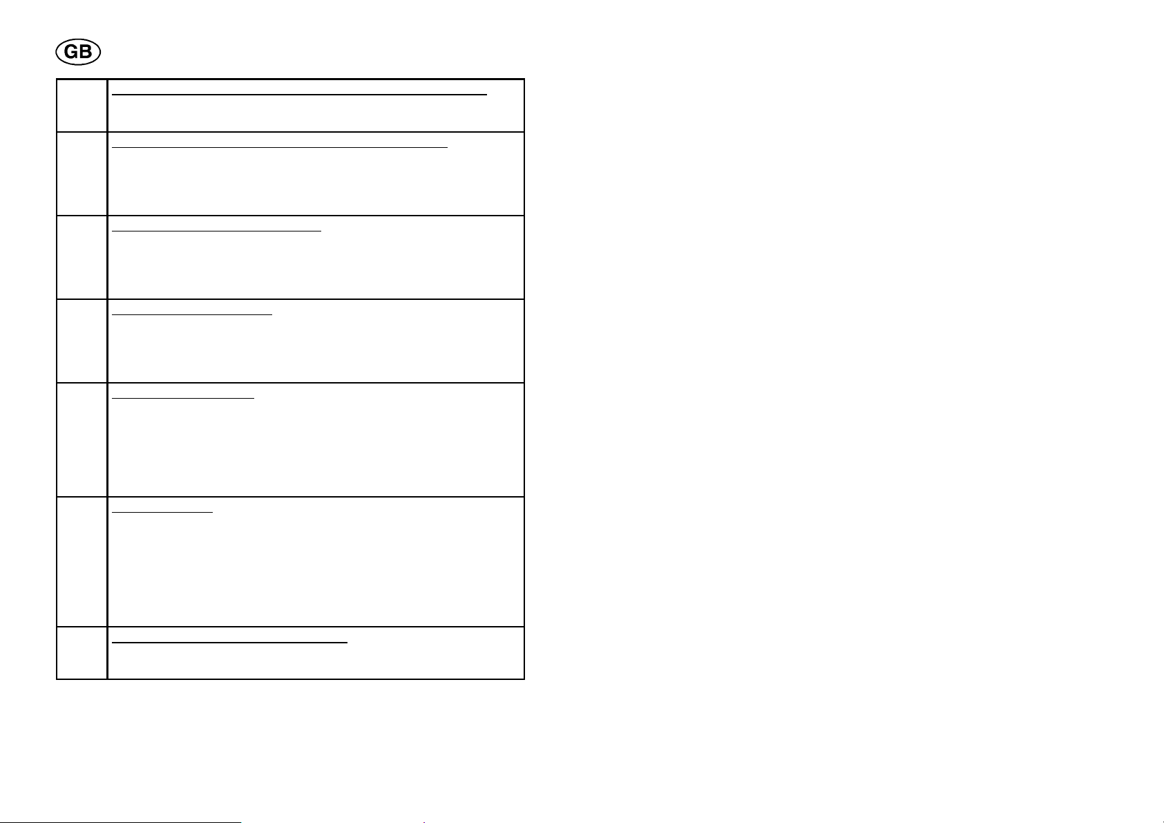
Error handling codes
Code Description
1 Program memory error (EPROM)
Cause: The program memory has lost a value. I.e the value in a
particular memory position no longer agrees with the original value. No functions are blocked through this error.
Measure: Voltage disconnection necessary for resetting. If the
error remains, call in a service technician.
2 Error in the microprocessor RAM
Cause: The microprocessor cannot write/read a certain memory
position in its own internal memory.
No functions are blocked through this error.
Measure: Voltage disconnection necessary for resetting. If the
error remains, call in a service technician.
3 Error in external RAM
Cause: The microprocessor cannot write/read a certain memory
position in its own external memory.
No functions are blocked through this error.
Measure: Voltage disconnection necessary for resetting. If the
error remains, call in a service technician.
4 Voltage drop in the 5 V supply voltage
Cause: Supply voltage too high.
All normal microprocessor activities cease, waiting for switch--off.
Measure: Voltage disconnection necessary for resetting. If the
error remains, call in a service technician.
dpa8d1ec
-- 6 6 --

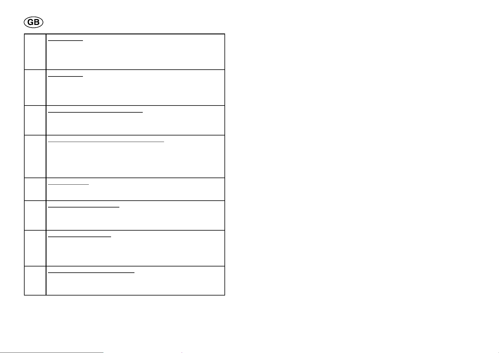
5 High + DC voltage outside limit value
Cause: Voltage too high or too low. Too high a voltage can be due
to powerful transients on the mains supply or to a weak supply
system (high inductance on the mains)
The welding power source is automatically switched off.
Measure: Voltage disconnection necessary for resetting. If the
error remains, call in a service technician.
6 High temperature
Cause: The thermal cut--out has tripped.
The welding power source is automatically switched off and cannot be switched on again until the temperature has gone down
and the cut--out is reset.
Measure: Check that the cooling air intake/outlet are not blocked
or dirty. Check that the work cycle does not exceed the ratings.
7 High primary current
Cause: Current too high in the welding power source.
The welding power source is automatically switched off and permanently blocked.
Measure: Voltage disconnection necessary for resetting. If the
error remains, call in a service technician.
8 Low battery voltage, weld data card (control box)
Cause: Battery voltage too low.
No functions are blocked through this error.
Measure: Make a backup on a PC--card. Call in a service technician.
8 Supply voltage +15 VC, PC--card (welding power source)
Cause: Voltage too high or too low.
Measure: Call in a service technician.
8 Supply voltage +15 V, motor card (rotation/wire) (weaving/
AVC)
Cause: Voltage too low.
Measure: Call in a service technician.
9 Supply voltage --15V, PC--card (welding power source)
Cause: The voltage is either too high or too low.
Measure: Call in a service technician.
9 Supply voltage +60 V, motor card (rotation/wire)(weaving/
AVC)
Cause: Current too low.
Measure: Call in a service technician.
dpa8d1ec
-- 6 7 --
10 Supply voltage +15 VB, PC--card (welding power source)
Cause: Voltage too high or too low.
Measure: Call in a service technician.
11 Incorrect current, PC--card (welding power source)
Cause: The welding power source failed in supplying the current
determined by the processor.
No functions are blocked through this error.
Measure: Call in a service technician.
12 Communication error (warning)
Cause: The CAN circuit error counter shows too high value.
The contact with the control box can be broken. This can result
from occasional overload.
Measure: Check the handling of the program during welding.
13 Incorrect rotation speed
Cause: Cannot keep up the speed determined by the processor.
The welding is interrupted
Measure: Check the cabling. If the error remains, call in a service
technician.
14 Communication error
Cause: The CAN circuit error counter shows too high value.
The welding process is stopped. This can result from occasional
overload.
Measure: Check the handling of the program during welding. Voltage disconnection necessary for resetting. If the error remains,
call in a service technician.
15 Lost messages
Cause: A message has been overwritten by another message. A
too frequent use of the pushbuttons on the control box, during
welding, may cause this fault.
The welding process is stopped.
Measure: Check the handling of the program during welding. Voltage disconnection necessary for resetting. If the error remains,
call in a service technician.
16 Incorrect wire feed / weaving speed
Cause: Cannot keep up the speed determined by the processor.
Measure: Check the cabling.
dpa8d1ec
-- 6 8 --
17 Contact lost
Cause: The control box has lost contact with one or both the mo-
tor units. Activities in progress are disabled.
Measure: Check the cabling. If the error remains, call in a service
technician.
18 Contact lost
Cause: The control box has lost contact with the power source.
Activities in progress are disabled.
Measure: Check the cabling. If the error remains, call in a service
technician.
19 Error in computer memory (RAM)
Cause: Can result from program upgrading.
Measure: Switch on the mains voltage, and automatic resetting is
effected.
20 Unpermitted setting values stored (RAM)
Cause: Unpermitted values found at the start. The error may re-
sult from software upgrading.
All data in the control box are deleted.
Measure: Switch on the mains voltage, and automatic resetting is
effected.
21 Current limit 1
Cause: Motor overload for rotation or weaving.
Measure: Check the welding tool and its cabeling.
22 Spill in buffer transmitter
Cause: The buffer transmitter is full. Activities in progress are dis-
abled.
Measure: Check the handling of the program during welding.
23 Spill in buffer receiver
Cause: CAN messages are received faster than the weld data
card can cope with. Activities in progress are disabled.
Measure: Check the handling of the welding program during welding.
25 Incompatible weld data format
Cause: TriedtostorewelddataonaPC--card.ThePC--cardcon-
tained other data format than the weld data memory.
Measure: Use another PC--card.
dpa8d1ec
-- 6 9 --

26 Watchdog
Cause: Something prevented the processor executing its normal
tasks in the program.
No functions are blocked through this error.
Measure: Check the handling of the welding program during welding.
27 Current limit 2
Cause: Motor overload for WEAVE/AVC, ROT/WIRE
Measure: Check the welding tool.
28 Spill in the stack
Cause: The internal memory is full. The error may be caused by
abnormal load on the processor.
Measure: Check the handling of the welding program during welding.
29 No water flow
Cause: The cooling water flow has gone down below 0.7 l/min.
Activities in progress are disabled.
Measure: Check the cooling water.
30 Contact lost with the TIG--card
Cause: The control box has lost contact with the TIG--card.
Activities in progress are disabled.
Measure: Check the cabling. If the error remains, call in a service
technician.
31 No response from the display unit
Cause: The microprocessor gets no acknowledgement from the
display unit.
Measure: Call in a service technician.
32 No gas flow
Cause: The gas flow has gone down below 6 l/min.
Measure: Check the gas valve, gas hoses and connections.
dpa8d1ec
-- 7 0 --

10.2 Incorrect editing codes
Codes depending on incorrect editing come up in the digit box when the
wrong key is activated. The error code number always starts with
p.
Code
13 Error in running the program.
110 Working area not empty when a program is recalled from the libra-
ry.
111 The program number does not exist in the library.
131 Key activation prohibited during welding.
132 Key activation prohibited during welding with special pulsing.
133 Permitted only during welding.
134 PC--card missing.
135 PC--card model for the welding power source (LTP 450) not accep-
ted.
136 Wrong program version of PC--card.
160 Working area is full.
163 The value in the digit box cannot be interpreted by the control box.
176 Welding program not accepted for welding.
177 Welding start prohibited in this program position in the control box.
178 The reset function does not work; must be preceded by a stop.
198 Welding start prohibited in manual program when the motors are
activated.
199 Welding start prohibited when activities are going on in the library.
204 A sector value cannot be changed so as to be placed before the
previous sector or after the following one.
205 A key is activated on the control box when the tool is started.
206 Tool code for the connected tool is missing.
207 Tool code not accepted.
212 Soft key not activated.
213 Delete state: Key prohibited.
Cause
dpa8d1ec
-- 7 1 --

221 Key not defined in this state.
222 When starting: Only tool code permitted.
223 Delete state: Key not defined.
229 Corr. state: Key activation prohibited.
233 Desired slope function: Parameter empty or not defined.
252 The tool code of the connected tool does not correspond to the
one of the welding program in the working area.
11 SHOW CURRENT PARAMETER VALUES
11.1 Field of applicatio n
Using this function it is possible to view the measured values of different
welding parameters in the course of welding. The values are updated every
0.5 seconds.
The following parameter groups can show actual parameter values:
Welding current Wire feed speed
Rotation speed Gas
Arc voltage control (AVC) Weaving
dpa8d1ec
-- 7 2 --
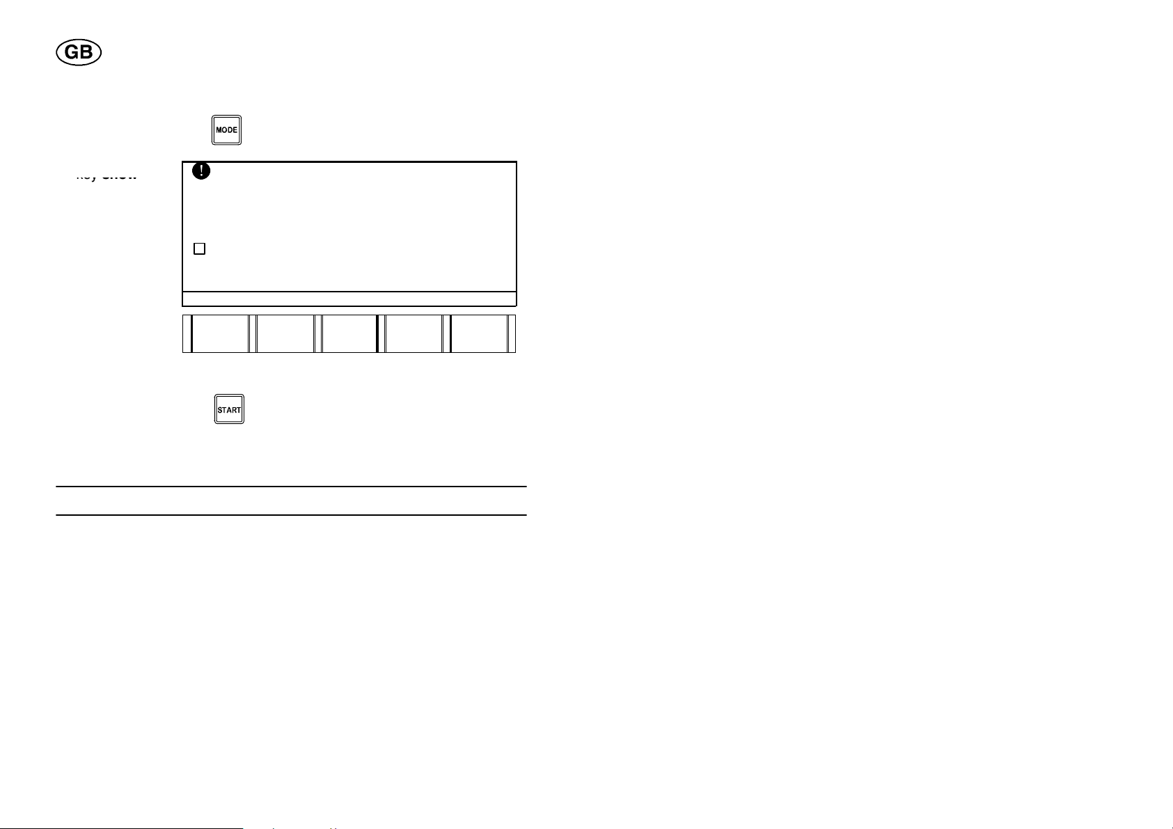
11.2 How to view actual parameter values
Pressthesof
t
keyshow
S Press the MODE key and you get to the Auxiliary Functions.
S
key show
parameter.
LANGUAGE "
ERROR LOG "
SHOW ACTUAL PARAMETER VALUES
SOFTWARE UPGRADE "
SOFTWARE KEY "
AUXILIARY FUNCTIONS
LAN-GUAGE
ERROR
LOG
SHOW
PARA-METER
SOFT-WARE
UPGR.
SOFT-WARE
KEY
Result: SHOW ACTUAL PARAMETER VALUES is marked and you have
activated show actual parameter values.
S Press the START key
to start welding.
S Press the desired parameter key.
The actual parameter values can now be viewed in the display.
12 SOFTWARE UPGRADE
12.1 Application field
Using the upgradE function you can replace (upgrade) programs in the
different units (PC--cards) of the welding equipment by new software from a
PC--card.
By unit is here meant a PC--card, containing software that can be
upgraded.
dpa8d1ec
-- 7 3 --

12.2 Menu explanation
SYSTEM VERSION. 1.00B
BOOT SOFTWARE 1.12
j POWER SOURCE 1.00 2.00
j ROT/WIRE UNIT ? --
j WEAVE/AVCUNIT 0.00 --
j WELD DATA UNIT 0.00 --
SOFTWARE UPGRADE
Unit Curr.ver PC--card
NEXT
#
j
j
QUIT UP--
GRADE
Curr--ver Describes which program version that is active in
this unit.
PC--card Describes the program version stored on the
PC--card.
? A unit exists but the computer does not know
which version it is.
-- There is no program for this unit on the PC--card.
SYSTEM VERSION Indicates the program version stored on the PC--
card. A program version can consist of 1--4 programs (1 for each unit).
BOOT SOFTWARE Program for upgrade handling.
POWER SOURCE PC--card for controlling the welding power sour-
ce.
ROT/WIRE UNIT PC--card for controlling the rotation and wire feed
motors.
WEAVE/AVC UNIT PC--card for controlling the weaving and AVC
motors.
WELD DATA UNIT The PC--card in the control box.
dpa8d1ec
-- 7 4 --

12.3 How to upgrade
Pressthesoftkeysoftware
upgrade
.
When upgrading the control box, all existing weld data will be
deleted. Do not forget to store the data on a PC--card before the
upgrade procedure is started.
To upgrade the ROT/WIRE , WEAVE/AVC WELD DATA (control box) unit,
proceed in the same way as for the POWER SOURCE.
Upgrading the power source unit
Make sure the mains voltage for the welding power source will
not be disconnected in the course of upgrading.
S Insert the PC--card containing the upgrading program.
S Press the MODE key
to get to the auxiliary functions.
S
upgrade.
LANGUAGE "
ERROR LOG "
SHOW ACTUAL PARAMETER VALUES
SOFTWARE UPGRADE "
SOFTWARE KEY "
LAN-GUAGE
AUXILIARY FUNCTIONS
ERROR
LOG
SHOW
PARA- METER
Result: You have come to the software upgrade menu.
dpa8d1ec
-- 7 5 --
SOFT
WARE
UPGR.
SOFT-WARE
KEY

In this example the program version of the PC--card only consists of one
Pressthesof
t
k
ttill
g
gettopowe
r
Pressthesof
t
k
upgrade program for the power source unit.
The following display comes up.
S
ey nex
et to “power
source”.
you
Unit Curr.ver PC--card
SYSTEM VERSION. 1.00B
BOOT SOFTWARE 1.12
j POWER SOURCE 1.00 2.00
j ROT/WIRE UNIT ? --
j WEAVE/AVC UNIT 0.00 --
j WELD DATA UNIT 0.00 --
NEXT
#
SOFTWARE UPGRADE
j
j
QUIT UP
GRADE
S Press the second soft key to mark the power source unit (gets ticked
off).
If further units are to be upgraded, they shall be marked in the same
way.
By pressing the second soft key once again, the selection marked is
cancelled (the marking disappears).
S
ey upgrade.
Unit Curr.ver PC--card
SYSTEM VERSION. 1,00B
BOOT SOFTWARE. 1,12
j POWER SOURCE 1.00 2.00
j ROT/WIRE UNIT ? --
j WEAVE/AVD UNIT 0.00 --
j WELD DATA UNIT 0,00 --
SOFTWARE UPGRADE
NEXT
#
dpa8d1ec
j
j
-- 7 6 --
QUIT UP--
GRADE

A dialogue box comes up in the display.
Pressthesof
t
k
p
g
upgrading
S
u
ey yesfor
rading.
.
SOFTWARE UPGRADE
THE SOFTWARE UPGRADING CAN
TAKE UP TO 5 MIN/UNIT AND.
CANNOT BE INTERRUPTED!
DO YOU STILL WANT TO DO IT ?
YES NO
The following dialogue box comes up in the display while upgrading:
SOFTWARE UPGRADE
DO NOT SWITCH OF THE EQUIPMENT
DURING THIS PROCESS!!
UPGRADING POWER SOURCE .....
23% completed
kkkkkkkkkkkkkkkkk
After completed upgrading the following comes up in the display:
SOFTWARE UPGRADE
SUCCESSFUL UPGRADE!
YOU MAY NOW RESTART THE EQUIPMENT !
Result: The power source unit has been upgraded to program version 2.00.
dpa8d1ec
-- 7 7 --

To make it possible to use the welding equipment, restart the welding power
source by
S Turning the mains voltage switch to position 0.
S Turning the mains voltage switch to position 1.
12.4 Measures to be taken when the upgrading of the
power source units failed
The software upgrade can for example fail if the supply voltage for the
welding power source is interrupted while upgrading is going on.
Failure in upgrading the power source, rot/wire and weave/A VC units
The following dialogue box comes up in the display when the software
upgrade has failed:
SOFTWARE UPGRADE
UPGRADING PROCESS FAILED!: 6
UNIT: 2!
Try once more to upgrade:
S Turn the mains voltage switch on the power source to position 0.
S Hold down the fourth one of the five soft keys on the control box and turn
the mains voltage switch to position 1.
Hold down the soft key until a double--squeak is heard.
The welding power source starts again, the power source, rot/wire ,
pendl/AVC units in an upgrade position, permitting a new program
upgrade.
The control box shows the upgrade menu display.
Repeat the program procedure “how to upgrade”, see page 75.
dpa8d1ec
-- 7 8 --

12.5 Measures to be taken when the upgrading of the
control box failed
The software upgrade can for example fail if the supply voltage for the
welding power source is interrupted while upgrading is going on.
Should this happen the first fifteen seconds during the upgrade
procedure, an ESAB service technician must be called in.
Try once more to upgrade:
S Turn the mains voltage switch on the welding power source to position 0.
S Insert the PC--card containing the upgrade program for the control box.
S Hold down the fifth one of the five soft keys at the same time as you turn
the mains voltage switch to position 1.
Hold down the soft key until a double--squeak is heard.
While the control box is being upgraded the display is empty. When the
procedure is finished, the control box will start up in the normal way .
The upgrade procedure takes about 5 minutes.
N.B. Do not switch off the welding power source while upgrading is going
on.
If it still does not work, call in a service technician.
dpa8d1ec
-- 7 9 --
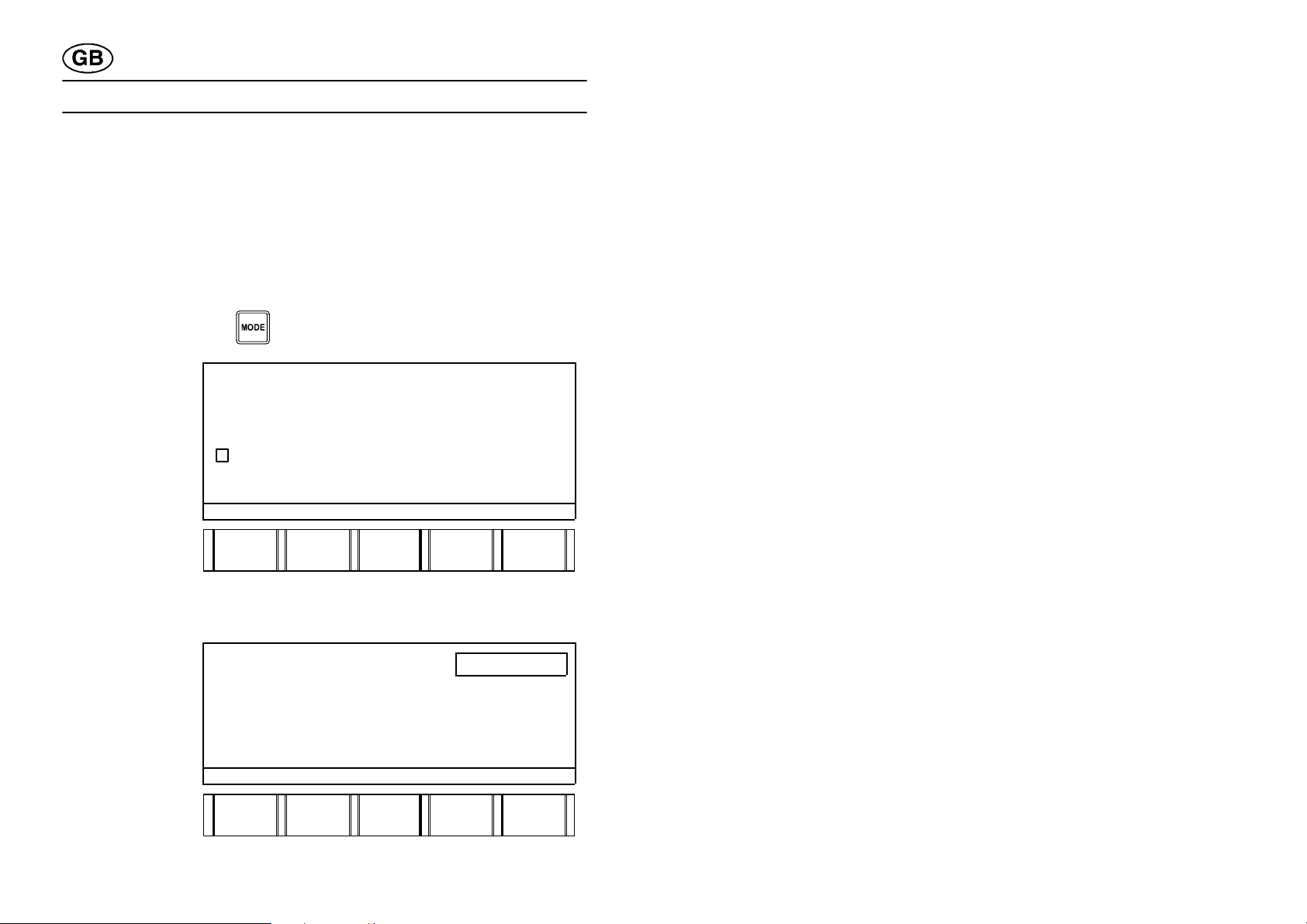
13 SOFWARE KEY
Pressthesoftwarekey
Pressthesof
t
13.1 General
The software key is intended for locking certain functions, such as the
modification of setting data in a welding program and the access to the
auxiliary functions.
13.2 Locking the control box
S Press the MODE key to get to the auxiliary functions.
S
.
LANGUAGE "
ERROR LOG "
SHOW ACTUAL PARAMETER VALUES
SOFTWARE UPGRADE "
SOFTWARE KEY "
AUXILIARY FUNCTIONS
LAN-GUAGE
ERROR
LOG
SHOW
PARA- METER
SOFT--.
WARE
UPGR.
SOFT-WARE
KEY
Result: You have come to the software key menu.
S Enter 4 code numbers using the numerical keys.
S
key enter.
dpa8d1ec
SOFTWARE KEY 1234
KEY CODE (4 NUMBERS):
THE CONTROLBOX IS UNLOCKED!
LOCK UN--
LOCK
LIMITS QUIT ENTER
-- 8 0 --

The following display comes up:
Pressthesof
t
Enterth
e
,
S
key lock.
SOFTWARE KEY
KEY CODE (4 NUMBERS): 1234
THE CONTROLBOX IS UNLOCKED!
LOCK UN
LOCK
Result: The control box is locked.
S Press the key
to return to the working area.
13.3 Unlocking the control box
S Press the MODE key .
The following display comes up:
S
correct code (4
numbers,
e.g.1234) using
the numerical
keys.
THECONTROLBOXISLOCKED!
PLEASE, GIVE LIMITSKEY CODE (4 NUMBERS):
LIMITS. QUIT ENTER
. ENTER
Each code number entered is acknowledged by :
S Press the soft key enter.
Result: The control box is unlocked and you have come to the auxiliary
function menu.
dpa8d1ec
-- 8 1 --
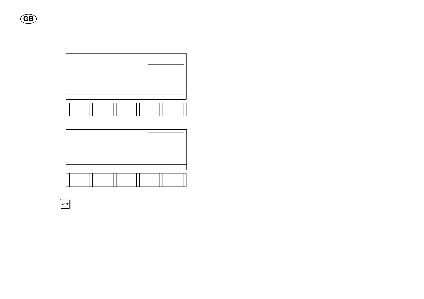
13.4 Changing the code
Pressthesof
t
Pressthesof
t
S Enter 4 new code numbers using the numerical keys.
S
key enter.
SOFTWARE KEY 1111
KEY CODE (4 NUMBERS): 1234
THE CONTROLBOX IS UNLOCKED!
LOCK UN--
LOCK
LIMITS QUIT ENTER
The following display comes up:
S
key lock.
SOFTWARE KEY
KEY CODE (4 NUMBERS): 1234
THE CONTROLBOX IS UNLOCKED!
LOCK UN--
LOCK
LIMITS QUIT ENTER
Result: The control box has got a new code and is locked.
S Press the key
to return to the working area.
dpa8d1ec
-- 8 2 --

14 NOTEBOOK
14.1 Field of ap p licatio n
The notebook is used for making notes on for example:
S MATERIAL, TUBE DIAMETER, WALL THICKNESS, RUN NUMBER
S START POINT, WELD TIME
S ELECTRODE DIAMETER, ELECTRODE STICKOUT, ELECTRODE
ANGLE
S DISTANCE: ELECTRODE--WIRE, ELECTRODE--WORKPIECE
S WIRE TYPE, WIRE DIMENSION, ELECTRODE TYPE
S WELD GAS
S ROOT GAS
S START GAS
All notes are stored together with the welding program in the library.
14.2 How to enter data in the notebook
S Press the SHIFT key and the STEP key to get to the
notebook.
dpa8d1ec
NOTEBOOK Page 1(8)
MATERIAL
TUBE DIAMETER.
WALL THICKNESS
RUN NUMBER
(NEXT)
PAGE
MATER.
TUBE
DIAM.
-- 8 3 --
WALL
THICKN
RUN NO
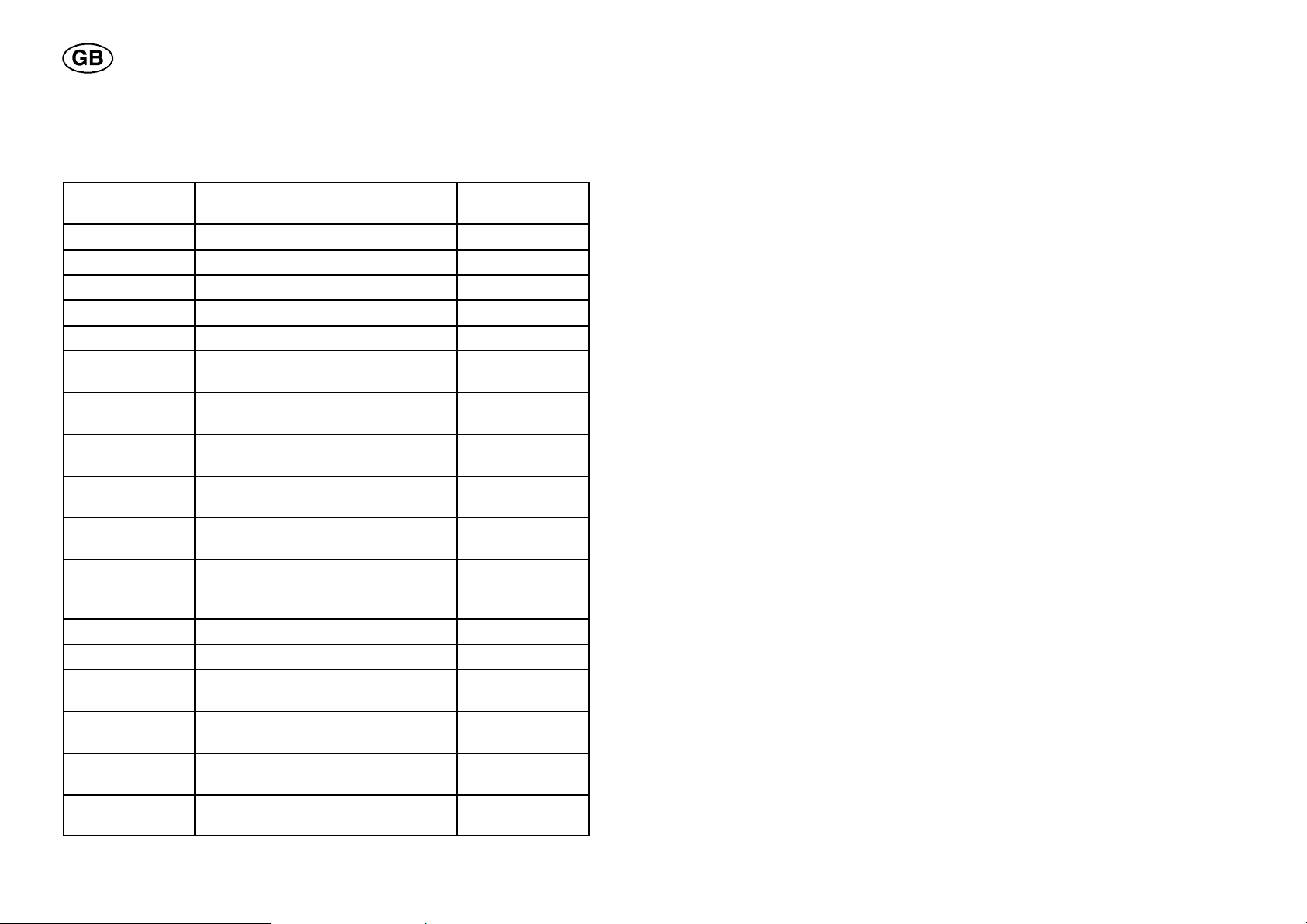
14.3 Example 2a:
Here a few examples of notes that can be made in the notebook.
Welding para-
Explanation Value
meter
Material SIS designation for stainless steel. 2333
Tube diameter The external diameter of the tube. 60 mm
Wall thickness The thickness of the tube wall. 3mm
Run number Which joint number. 2
Start point Where on the tube the start point is. 3 o’clock
Weld time The time required for running a wel-
1h20min30s
ding a program.
Electrode
diameter
Electrode
stick--out
Electrode angle The angle of the tungsten electrode
The diameter of the tungsten electrode.
The stick--out of the tungsten electrode from the electrode holder.
1.6 mm
5mm
30˚
in relation to the tube.
Distance:
Electrode--wire
Distance: Elec-trode--workpiece
The distance between the tungsten
electrode and the filler wire.
The distance between the tungsten
electrode and the workpiece (the
tube).
5mm
5mm
Wire type Type of filler wire used. OK 12.51
Wire dimension Dimension of the filler wire used. 0.8 mm
Electrode type Quality of tungsten electrode (thori-
2% Th, 2% La
um, lanthan).
Weld gas Weld gas components (argon, heli-
100 % Ar
um, hydrogen, nitrogen).
Root gas Root gas components (argon, heli-
100 % Ar
um, hydrogen, nitrogen).
Start gas Start gas components (argon, heli-
100 % He
um, hydrogen, nitrogen).
dpa8d1ec
-- 8 4 --
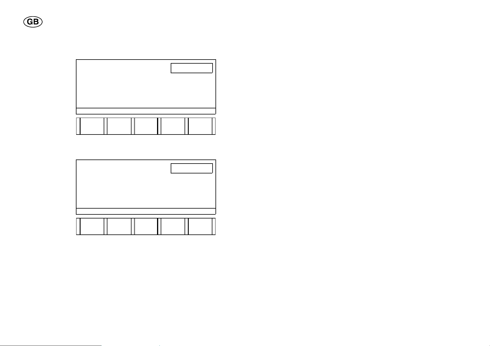
Material = 2333
Pressthesof
t
Pressthesof
t
ete
r
S Enter the value 2333 using the numerical keys.
S
key material.
NOTEBOOK Page 1(8)
MATERIAL
TUBE DIAMETER.
WALL THICKNESS
RUN NUMBER
2333
(NEXT)
PAGE
MATER.
TUBE
DIAM.
External tube diameter = 60 mm
S Enter the value 60 using the numerical keys.
S
key tube diam-
NOTEBOOK Page 1(8)
.
MATERIAL 2333
TUBE DIAMETER.
WALL THICKNESS
RUN NUMBER
(NEXT)
PAGE
MATER.
TUBE
DIAM.
TUBE
THICKN
60
TUBE
THICKN
RUN NO
RUN NO
dpa8d1ec
-- 8 5 --

Wall thickness = 3 mm
Pressthesof
t
nes
s
Pressthesof
t
numbe
r
S Enter the value 3 using the numerical keys.
S
key wall thick-
NOTEBOOK Page 1(8)
.
MATERIAL 2333
TUBE DIAMETER. 60. mm
WALL THICKNESS
RUN NUMBER
3
(NEXT)
PAGE
MATER.
TUBE
DIAM.
Run number = No 2
S Enter the value 2 using the numerical keys.
S
key run
S Press the soft
key next page.
NOTEBOOK Page 1(8)
MATERIAL 2333
TUBE DIAMETER 60.0 mm
WALL THICKNESS 3.00 mm
RUN NUMBER
(NEXT)
PAGE
MATER.
TUBE
DIAM.
WALL
THICKN
2
TUBE
THICKN
RUN NO
RUN NO
dpa8d1ec
-- 8 6 --
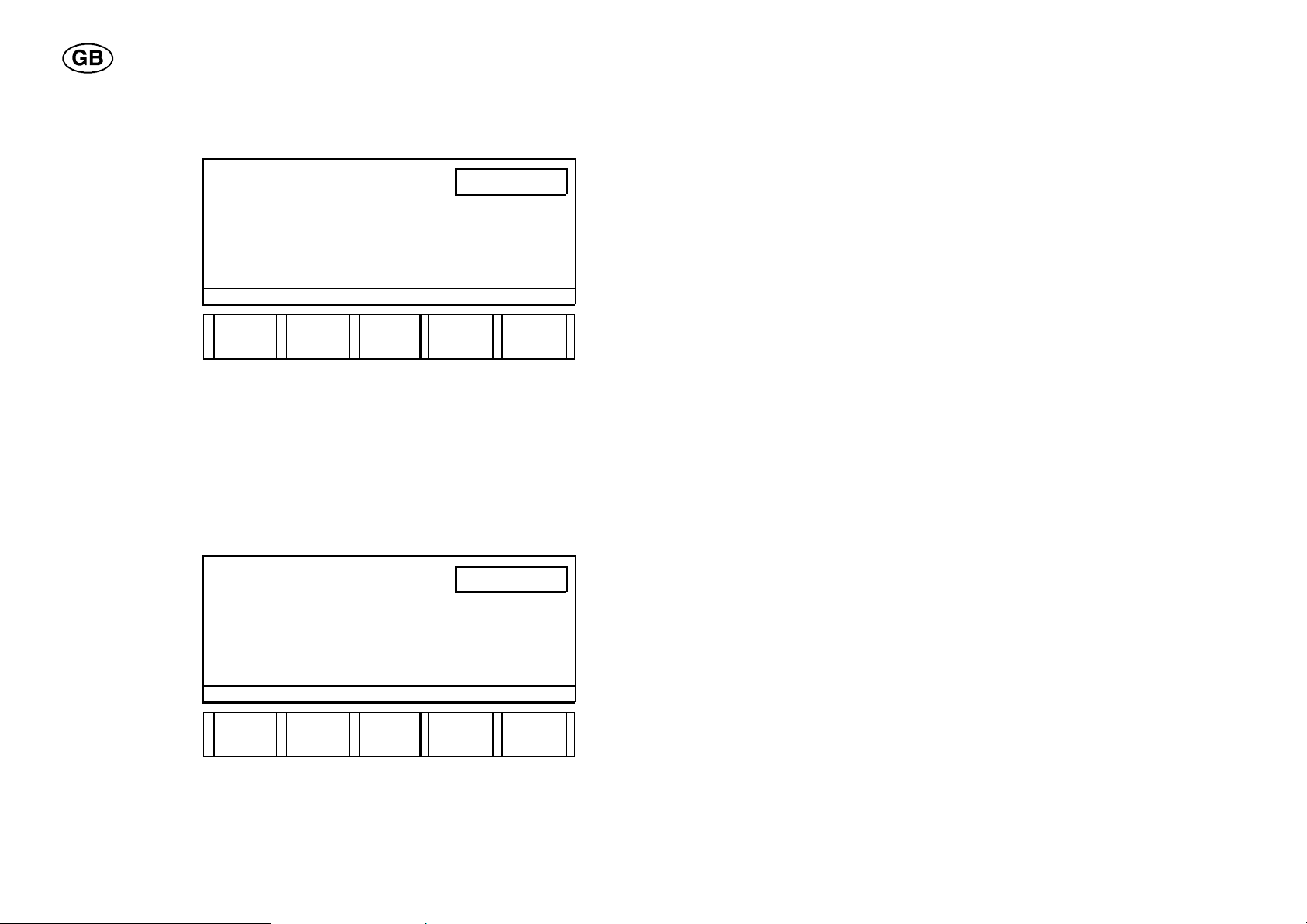
Start point = 3 o’clock
Pressthesof
t
Pressthesof
t
S Enter the value 3 using the numerical keys.
S
key start point.
NOTEBOOK Page 2(8)
START POINT
WELD TIME
3
(NEXT)
PAGE
START
POINT
HOUR
Welding time = 1 h 20 min 30 s
S Enter the value 1 using the numerical keys.
S Press the soft key hour.
S Enter the value 20 using the numerical keys.
S Press the soft key minute.
S Enter the value 30 using the numerical keys.
S Press the soft key second.
S
key next page.
NOTEBOOK Page 2(8)
START POINT 3 o’clock
WELD TIME 1 h
(NEXT)
PAGE
START
POINT
HOUR
20 min
30 s
MIN
MIN
SECOND
SECOND
dpa8d1ec
-- 8 7 --

Electrode diameter = 1.6
Pressthesof
t
Pressthesof
t
S Enter the value 1.6 using the numerical keys.
S
key diameter.
NOTEBOOK Page 3(8)
ELECTRODE DIAMETER
ELECTRODE STICKOUT
ELECTRODE ANGLE
1.6
(NEXT)
PAGE
DIAM.
STICK- -
OUT
Electrode stick--out = 5 mm
S Enter the value 5 using the numerical keys.
S
key stick--out.
NOTEBOOK Page 3(8)
ELECTRODE DIAMETER 1.6 mm
ELECTRODE STICKOUT
ELECTRODE ANGLE
(NEXT)
PAGE
DIAM.
STICK--
OUT
ANGLE
5
ANGLE
dpa8d1ec
-- 8 8 --

Electrode angle = 30˚
Pressthesof
t
Pressthesof
t
wir
e
S Enter the value 30 using the numerical keys.
S
key angle.
S Press the soft
key next page.
NOTEBOOK Page 3(8)
ELECTRODE DIAMETER 1.6 mm
ELECTRODE STICKOUT 5.0 mm
ELECTRODE ANGLE
30
(NEXT)
PAGE
DIAM.
STICK- -
OUT
Distance: Electrode--Wire = 5 mm
S Enter the value 5 using the numerical keys.
S
key electrode--
NOTEBOOK Page 4(8)
.
DISTANCE:
ELECTRODE -- WIRE
ELECT. -- WORKPIECE
(NEXT)
PAGE
ELECT.
-WIRE
ELECT.
--
WORKP.
ANGLE
5
dpa8d1ec
-- 8 9 --

Distance: Electrode--workpiece = 5 mm
Pressthesof
t
workpiece
Pressthesof
t
S Enter the value 5 using the numerical keys.
S
key electrode--
NOTEBOOK Page 4(8)
.
S Press the soft
key next page.
DISTANCE:
ELECTRODE -- WIRE 5.0 mm
ELECT. -- WORKPIECE
5
(NEXT)
PAGE
ELECT.
-WIRE
ELECT.
--
WORKP.
Wire quality = OK 12.51
S Enter the value 12.51 using the numerical keys.
S
key wire type.
NOTEBOOK Page 5(8)
WIRE TYPE
WIRE DIAMETER
ELECTRODE TYPE
(NEXT)
PAGE
WIRE
TYPE
WIRE.
DIAM.
12.51
ELECT.
%Th
ELECT.
%La
dpa8d1ec
-- 9 0 --

Wire dimension = 0.8 mm
Pressthesof
t
ete
r
Pressthesof
t
S Enter the value 0.8 using the numerical keys.
S
key wire diam-
NOTEBOOK Page 5(8)
.
WIRE TYPE 12.51
WIRE DIAMETER
ELECTRODE TYPE
0.8
(NEXT)
PAGE
WIRE
TYPE
WIRE.
DIAM.
Electrode quality = 2% Th, 2 % La
S Enter the value 2 using the numerical keys.
S Press the soft key electrode % Th.
S Enter the value 2 using the numerical keys.
S Press the soft key electrode % La.
S
key next page.
NOTEBOOK Page 5(8)
WIRE TYPE 12.51
WIRE DIAMETER 0.8 mm
ELECTRODE TYPE
(NEXT)
PAGE
WIRE
TYP
WIRE.
DIAM.
ELECT.
%Th
ELECT.
%Th
ELECT.
%La
ELECT.
%La
dpa8d1ec
-- 9 1 --

Weld gas = 100 % Ar
Pressthesof
t
Pressthesof
t
S Enter the value 100 using the numerical keys.
S
key % Argon.
S Press the soft
key next page.
NOTEBOOK Page 6(8)
WELD GAS
100
(NEXT)
PAGE
%Ar
%He
Root gas = 100 % Ar
S Enter the value 100 using the numerical keys.
S
key % Argon.
S Press the soft
key next page.
NOTEBOOK Page 7(8)
ROOT GAS
(NEXT)
PAGE
%Ar
%He
%H %N
100
%H %N
dpa8d1ec
-- 9 2 --

Start gas = 100 % He
Pressthesof
t
S Enter the value 100 using the numerical keys.
S
key % Helium.
NOTEBOOK Page 8(8)
START GAS
100
(NEXT)
PAGE
%Ar
%He
%H %N
S Press the keys SHIFT and STEP to return to the working
area.
dpa8d1ec
-- 9 3 --

15 MANUAL WELDING
15.1 Field of ap p licatio n
Used for normal manual TIG welding with a hand torch (see the respective
instruction manual).
15.2 How to create a welding program
To enable hand--welding it is necessary to create a welding program,
consisting of two sectors with the welding current and gas parameters
indicated. Note! Rotation must not be indicated.
15.3 Example 3a:
Start by entering the correct tool code TIG HAND TORCH.
This is a simple welding program, consisting of 2 sectors, sector 2 being a
stop sector.
Sector 1 Sector 2
Breakpoint 0.000 1.000
Welding current (continuous) (A) 80 0
Welding current (background cur-
rent) (A)
Welding current (pulse time) (s) 0.5 0.5
Welding current (background time)
(s)
Slope up (s) 2 -Slope down (s) -- 5
Gas preflow (weld gas) (s) 5 -Gas postflow (weld gas) (s) -- 10
40 40
0.5 0.5
dpa8d1ec
-- 9 4 --

Sector 1
Pressthesof
t
ouspeak
Pressthesof
t
ousback
Breakpoint
Sector 1 automatically is assigned the breakpoint 0.000, if nothing else is
indicated. Start by indicating the welding current parameter.
Welding current
Peak current = 80 A
S Press the key for WELDING CURRENT
.
The picture for setting the welding current comes up in the display.
S Enter the value 80 using the numerical keys.
S
key continu-
current.
SECTOR 1(1) 0.000
PEAK CURRENT A
BACKGR. CURRENT A
PEAK TIME s
BACKGR. TIME s
CONT/
PEQAK
CURR.
BACKGR
CURR.
PEAK
TIME
80
BACKGR
TIME
Result: PEAK CURRENT = 80 A in Sector 1.
Background current = 40 A
S Enter the value 40 using the numerical keys.
S
key continu-
-
ground current.
SECTOR 1(1) 0.000
PEAK CURRENT 80 A
BACKGR. CURRENT A
PEAK TIME s
BACKGR. TIME s
40
SPEC.
PULS
CONT/
PEAK
CURR.
dpa8d1ec
BACKGR
CURR.
-- 9 5 --
PEAK
TIME
BACKGR
TIME
SPEC.
PULS
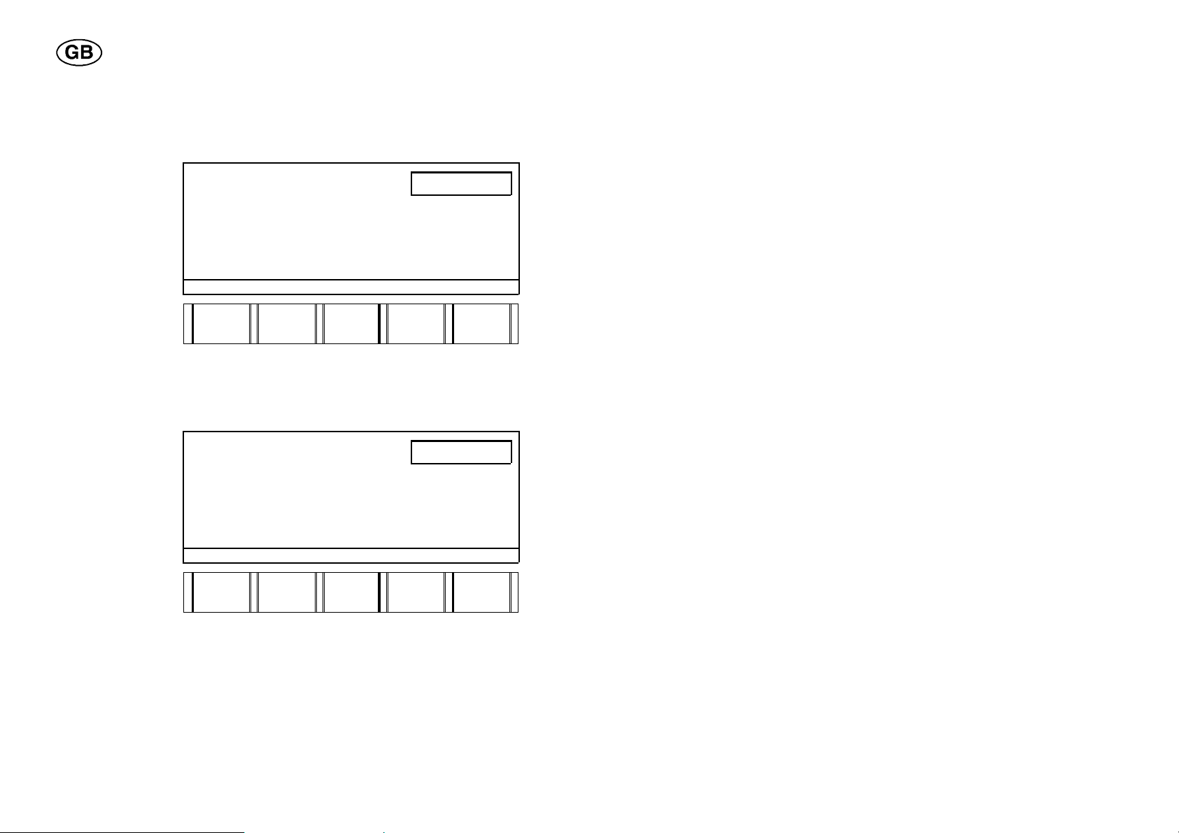
Result: BACKGROUND CURRENT = 40 A in sector 1.
Pressthesof
t
Pressthesof
t
groundtim
e
Pulse time = 0.5 s instead of 1.0
S Enter the value 0.5 using the numerical keys.
S
key peak time.
SECTOR 1(1) 0.000
1 PEAK CURRENT 80 A
BACKGR. CURRENT 40 A
PEAK TIME 1.00 s
BACKGR. TIME 1.00 s
0.5
CONT/
PEAK
CURR.
BACKGR
CURR.
PEAK
TIME
BACKGR
TIME
SPEC.
PULS
Result: PULSE TIME = 0.50 s instead of 1.00 s in sector 1.
Background time = 0.5 s instead of 1.0
S Enter the value 0.5 using the numerical keys.
S
key back-
.
SECTOR 1(1) 0.000
1 PEAK CURRENT 80 A
BACKGR. CURRENT 40 A
PEAK TIME 0. 50 s
BACKGR. TIME 1.00 s
CONT/
PEAK
CURR.
BACKGR
CURR.
PEAK
TIME
0.5
BACKGR
TIME
SPEC.
PULS
Result: BACKGROUND TIME = 0.50 s instead of 1.00 s in sector 1.
dpa8d1ec
-- 9 6 --
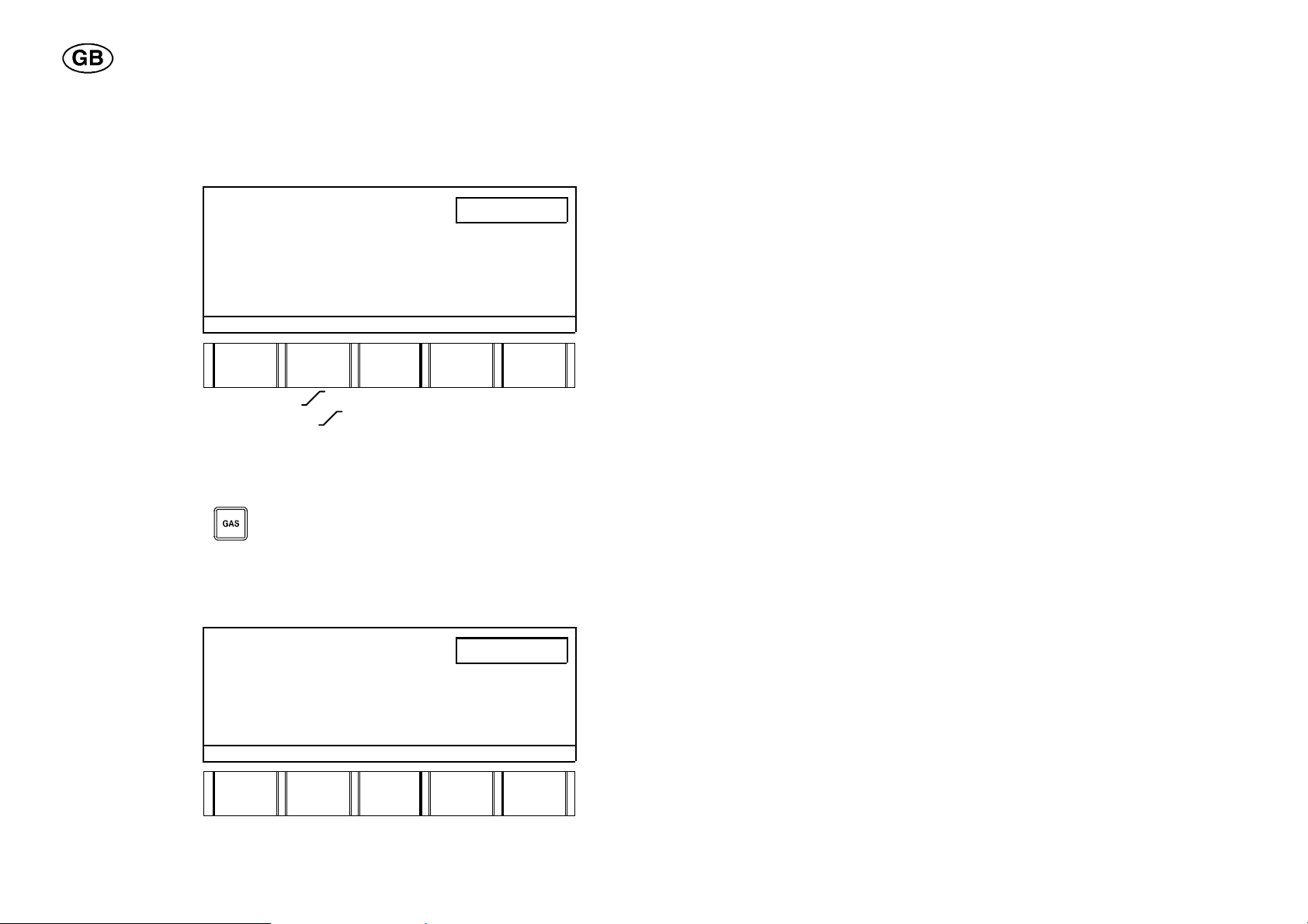
Slope
Enterth
eva
lue
numericalkeys
Pressthesof
t
Slope up = 2sfor peak current.
S Press the soft key continuous peak current.
S
2 using the
SECTOR 1(1) 0.000
.
S Press the
SLOPE key.
2 PEAK CURRENT 80 A
BACKGR. CURRENT 40 A
PEAK TIME 0.50 s
BACKGR. TIME 0.50 s
2
CONT/
PEAK
CURR.
BACKGR
CURR.
PEAK
TIME
BACKGR
TIME
SPEC.
PULS
Result: PEAK CURRENT = 80 A, 2.0 s in sector 1, and
BACKGROUND CURRENT = 40 A,
2.0 s in sector 1.
Gas
Gas preflow, weld gas = 5s.
S Press the gas key
.
S Enter the value 5 using the numerical keys.
The gas preflow is preset to 2 seconds, which applies if nothing else is
entered and indicated in the display at the start.
S
key weld gas.
SECTOR 1(1) 0.000
WELD GAS s
ROOT GAS s
START GAS s
WELD
GAS
ROOT
GAS
START
GAS
5
Result: WELD GAS = 5 s in sector 1.
dpa8d1ec
-- 9 7 --

Sector 2
Pressth
e
Pressthesof
t
ouspeak
Breakpoint
S Enter the value of the new breakpoint 1.010 using the numerical keys.
S
SECTOR key.
SECTOR 1(1) 0.000 1.010
1 WELD GAS 5 s
ROOT GAS s
START GAS s
WELD
GAS
ROOT
GAS
START
GAS
Result: Sector 2 out of 2 sectors in all.
Welding current
Pulse current = 0A
As sector 2 is to be a stop sector, the welding current must be set to 0
amperes.
S Press the key for WELDING CURRENT
.
S Enter the value 0 using the numerical keys.
S
key continu-
current.
SECTOR 2(2) 1.000
1 PEAK CURRENT 80 A
BACKGR CURRENT 40 A
PEAK TIME 0.50 s
BACKGR. TIME 0.50 s
CONT/
PEAK
CURR.
BACKGR
CURR.
PEAK
TIME
0
BACKGR
TIME
2,0 S
2.0 S
SPEC.
PULS
Result: PEAK CURRENT = 0 A in sector 2 (stop sector)
dpa8d1ec
-- 9 8 --

Slope
Enterth
eva
lue
numericalkeys
Pressthesof
t
Slope down = 5sfor peak current.
S Press the soft key continuous peak current.
S
5 using the
SECTOR 2(2) 1.000
.
S Press the
SLOPE key.
2 PEAK CURRENT 0 A
BACKGR CURRENT 40 A
PEAK TIME 0.50 s
BACKGR. TIME 0.50 s
5
CONT/
PEAK
CURR.
BACKGR
CURR.
PEAK
TIME
BACKGR
TIME
SPEC.
PULS
Result: PEAK CURRENT = 0 A, 5.0 s in sector 12, and
BACKGROUND CURRENT = 40 A,
5.0 s in sector 1.
Gas
Gas postflow, weld gas = 10 s in sector 2.
S Press the GAS key
.
S Enter the value 10 using the numerical keys.
The gas postflow is preset to 4 seconds, which applies if nothing else is
entered and indicated in the display at the start.
S
key weld gas.
SECTOR 2(2) 1.000
1WELDGAS s
ROOT GAS s
START GAS s
WELD
GAS
ROOT
GAS
START
GAS
10
Result: WELD GAS = 10 s in sector 2.
dpa8d1ec
-- 9 9 --

15.4 How to weld
Starting a welding sequence (arc strike)
S Press the torch contact and then release it again.
The parameter values for sector 1 (the start sector) apply throughout the
welding sequence.
Stopping a welding sequence
S Press the torch contact and then release it again.
The parameter values for sector 2 (the end sector) are used.
16 APPENDIX
16.1 Tool codes
Welding tool Size
PRB, PRC 8--17*
17--49*
33--90
60--170
PRH 6--40
25--90
40--115
PRD Indicate the number of cogs on the
gear ring, for ex. 1120.
POC 12--60
Manual TIG torch --
A25 automatic welding machine With rotation
Without rotation
*)
When the conversion kit PRB , PRC 8--17 is used, the tool code 17--49
applies.
When a drive unit with the gear ratio 134:1 is used, the tool code 8--17
applies.
dpa8d1ec
-- 1 0 0 --
 Loading...