

ESAB IEFC-S PT-24 Precision Plasmarc System with Integrated Flow Control (Separable) Installation manual / Instruction manual
Page 1

F-15-754
June, 2005
Installation, Operation and Maintenance Manual for the
IEFC-S
PT-24 Precision Plasmarc System
With Integrated Flow Control (Separable)
Gas Bundle
Ignition Console
Flow Console
Torch
Power Console
Cutting Systems
411 South Ebenezer Road
Florence, South Carolina, U.S.A.
Page 2

The equipment described in this manual is
potentially hazardous. Use caution when installing,
operating and maintaining this equipment.
Purchaser is solely responsible for the safe
operation and use of all products purchased,
including compliance with OSHA and other
government standards. ESAB Cutting
Systems has no liability for personal injury or
other damage arising out of the use of any
product manufactured or sold be ESAB. See
standard ESAB terms and conditions of sale
for a specific statement of ESAB’s
responsibilities and limitations on its liability.
ESAB Cutting Systems first priority is total
customer satisfaction. We constantly look for
ways to improve our products, service and
documentation. As a result, we make
enhancements and/or design changes as
required. ESAB makes every possible effort to
ensure our documentation is current. We
cannot guarantee that each piece of
documentation received by our customers
reflects the latest design enhancements.
Therefore, the information contained in this
document is subject to change without notice.
This manual is ESAB Part Number F15754
This manual is for the convenience and use of the
cutting machine purchaser. It is not a contract or
other obligation on the part of ESAB Cutting
Systems.
© ESAB Cutting Systems, 2002
Printed in U.S.A.
Page 3

Precision Plasma IEFC-S - CE Table of Contents
Section 1 Safety Page 1--(_)
1.1 Introducti o n........................................................................................ 1
1.2 Safety Notations And Symbols............................................................ 2
1.3 General Safety Information .................................................................. 3
1.4 Installation Precautions........................................................................ 4
1.5 Electrical Grounding............................................................................ 5
1.6 Operating A Plasma Cutting Machine .................................................. 6-10
1.7 Service Precautions............................................................................. 11
1.8 Safety References............................................................................... 12-17
Section 2 Description Page 2--(_)
2.1 General............................................................................................... 1
2.2 Scope................................................................................................. 1
2.3 Package Options Available.................................................................. 2
2.4 Technical Specifications
2.4.1 Precision Plasma System ........................................................... 3
2.4.2 Plasma Gas ............................................................................... 4
2.4.3 Start Gas ................................................................................... 4
2.4.4 Secondary Gas .......................................................................... 4
2.4.5 Cut Gas ..................................................................................... 4
2.4.6 PT-24 Torch ............................................................................... 4
i
Page 4

Precision Plasma IEFC-S - CE Table of Contents
Section 3 Installation Page 3--(_)
3.1 General.............................................................................................. 1
3.2 Equipment Required........................................................................... 1
3.3 Location............................................................................................. 1
3.4 Primary Electrical Input Connections ................................................... 2-3
3.5 Alternate Connection Locations for IFC............................................... 4
3.6 IFC Basic Component Identification..................................................... 4
3.7 Ignition Console Basic Components and Connection Points................ 5
3.8 Interconnecting Lines.......................................................................... 6
3.9 Joining Ignition and Gas Consoles....................................................... 7
3.10 Connection Separated Gas and Ignition Consoles............................. 8
3.11 Power Console Connect io n s............................................................. 9
3.12 Voltage Selector Switch.................................................................... 9
3.13 Separated Gas and Ignition Console Interconnection Diagram........... 10-11
3.14 Combined Gas and Ignition Console Interconnection Diagram........... 12-13
3.15 Input to Gas Console........................................................................ 14-15
3.16 Input to Power Console.................................................................... 16
3.17 Torch Mounting................................................................................ 17
3.18 Torch Coolant................................................................................... 18
3.19 Inspection Of Gas And Coolant Lines................................................. 18
3.20 Using the 5 Solenoid Torch Manifold................................................. 19
3.21 Converting IEFC-S Gas Console Manifold to Accommodate a 4
Solenoid Torch Manifold....................................................................
19-20
ii
Page 5

Precision Plasma IEFC-S - CE Table of Contents
Section 4 Operation Page 4--(_)
4.1 Power Supply Controls
4.1.1 Main Power Switch ..................................................................... 1
4.1.2 Pilot Arc Switch........................................................................... 1
4.1.3 Fault Indicator Lights................................................................... 2
4.1.4 Meters........................................................................................ 2
4.1.5 Current Control Switch................................................................ 2
4.2 Cut Quality..........................................................................................
4.2.1 Introduction................................................................................. 3
4.2.2 Cut Angle.................................................................................... 4
4.2.3 Cut Flatness................................................................................ 5
4.2.4 Surface Finish............................................................................. 6
4.2.5 Dross.......................................................................................... 7-8
4.2.6 Dimensional Accuracy................................................................. 9
4.3 Influence of Gas Options on Cut Quality
4.3.1 Introduction................................................................................. 10
4.3.2 Aluminum.................................................................................... 10
4.3.3 Carbon Steel............................................................................... 11
4.3.4 Stainless Steel............................................................................. 12-13
4.4 Process Data
4.4.1 Introduction................................................................................. 15
4.4.2 Process Data Settings................................................................. 16-61
Aluminum............................................................................. 16-23
Carbon Steel........................................................................ 24-33
Stainless Steel...................................................................... 34-61
4.4.3 Relationship of Kerf Width to Amperes and Material Thickness..... 62
4.4.3.1 Aluminum Kerf Values.......................................................... 62
4.4.3.2 Carbon Steel Kerf Valu es..................................................... 64
4.4.3.3 Stainless Steel Kerf Values O2/N2/O2.................................... 67
4.4.3.4 Stainless Steel Kerf Values Air/Air/CH4................................. 68
4.4.3.5 Stainless Steel Kerf Values N2/N2/CH4.................................. 69
4.4.3.6 Stainless Steel Kerf Values N2/N2......................................... 70
4.4.3.7 Stainless Steel Kerf Values Air/Air........................................ 72
Plasma Marking Data........................................................... 74
iii
Page 6

Precision Plasma IEFC-S - CE Table of Contents
Section 5 Maintenance Page 5--(_)
5.1 General.............................................................................................. 1
5.2 Inspection and Cleaning...................................................................... 1
5.3 PT-24 Torch Description..................................................................... 2-4
5.4 IEFC-S Fluid Schematic...................................................................... 3
5.4 Torch Mainten a n ce............................................................................. 5-6
5.5 PT-24 Consumable Disassembly and Inspection................................. 7-10
5.6 PT-24 Torch Re-Assembly.................................................................. 11-12
5.7 Flow Control....................................................................................... 13
5.8 Proportional Valve Removal ................................................................. 14
Section 6 Troubleshooting Page 6--(_)
6.1 General Safety.................................................................................... 1
6.2 Troubleshooting Guide........................................................................ 2
6.2.1 Reduced Consumable Life.......................................................... 2
6.2.2 Poor Cut Quality......................................................................... 3
6.2.3 No Pilot Arc................................................................................ 3
6.2.4 No Arc Transfer .......................................................................... 3
6.2.5 No Preflow.................................................................................. 3
6.2.6 Torch Fails to Fire....................................................................... 3
6.2.7 Nozzle Life Extremely Short......................................................... 4
6.2.8 Short Electrod e L i fe.................................................................... 4
6.2.9 Short Electrode AND Nozzle Life................................................. 4
6.3 IEFC-S Fluid Schematic...................................................................... 5
IEFC-S Man ifo ld Valve Identification............................................. 5
6.4 IEFC-S Electrical Schematic................................................................ 6-7
6.5 Ignition Console Electrical Schematic.................................................. 8
6.6 Ignition Console Fluid Schematic......................................................... 8
6.7 Precision Plasma Power Source Electrical Schematic.......................... 10-11
6.8 Precision Plasma Power Source Wiring Diagram (includes CE Version) 12-16
6.7 Power Module Schematic – CE Version............................................... 18-19
6.8 Precision Plasma Power Module Wiring Diagram – CE Version ............ 20-21
6.9 Torch Manifold.................................................................................... 22
iv
Page 7

Precision Plasma IEFC-S - CE Table of Contents
Section 7 Replacement Parts Page 7--(_)
7.1 General............................................................................................... 1
7.2 Ordering............................................................................................. 1
7.3 Plasmarc Power Source – Ext erior Components.................................. 2-7
7.4 Plasmarc Power Source – Internal Components .................................. 8-17
7.5 Power Source Module......................................................................... 18-25
7.6 IEFC-S Gas Console........................................................................... 26-27
7.7 IEFC-S Gas Man i fo ld........................................................................... 28-29
7.8 IEFC-S Ignition Console...................................................................... 30-31
7.9 PT-24 Torch Assembly IFC Series......................................................
7.10 Torch Manifold 5 solenoid .................................................................
7.11 Interface Cables and Hoses...............................................................
32-33
34-35
36-37
Customer/Technical Information Back Manual Cover
v
Page 8

Precision Plasma IEFC-S - CE Table of Contents
This page intentionally left blank.
vi
Page 9

SECTION 1 SAFETY
1.1 Introduction
The process of cutting metals with plasma equipment
provides industry with a valuable and versatile tool.
ESAB cutting machines are designed to provide both
operation safety and efficiency. However, as with any
machine tool, sensible attention to operating
procedures, precautions, and safe practices is
necessary to achieve a full measure of usefulness.
Whether an individual is involved with operation,
servicing, or as an observer, compliance with
established precautions and safe practices must be
accomplished. Failure to observe certain precautions
could result in serious personnel injury or severe
equipment damage. The following precautions are
general guidelines applicable when working with
cutting machines. More explicit precautions pertaining
to the basic machine and accessories are found in the
instruction literature. For a wide scope of safety
information on the field of cutting and welding
apparatus, obtain and read the publications listed in
the Recommended References.
PT-24 Precision Plasma System IEFC -S -
1-1
Page 10
SECTION 1 SAFETY
1.2 Safety Notations And Symbols
!
DANGER
!
The following words and symbols are used throughout
this manual. They indicate different levels of required
safety involvement.
ALERT or ATTENTION. Your safety is involved
or potential equipment failure exists. Used with
other symbols and information.
Used to call attention to immediate hazards
which, if not avoided, will result in serious
personal injury o r los s o f life.
WARNING
!
CAUTION
!
CAUTION
NOTICE
Used to call attention to potential hazards that
could result in personal injury or loss of life.
Used to call attention to hazards that could result
in minor personal injury or equipment damage.
Used to call attention to minor hazards to
equipment.
Used to call attention to important installation,
operation or maintenance information not
directly related to sa fe ty hazards.
1-2
PT-24 Precision Plasma System IEFC -S -
Page 11
SECTION 1 SAFETY
1.3 General Safety Information
NOTICE
Some subjects listed are not related specifically to
the type of equipment covered in this manual.
However, the safety principles still apply. They are
offered as a reminder that this equipment or
related apparatus should be operated with
alertness and understanding. Safety of operators,
technicians, maintenance workers and observers
should not be taken for granted.
Machinery may start automatically.
WARNING
!
Equipment positioning mechanized plasma torches
moves in various directions and speeds.
· Moving machinery can crush .
· Only qualified personnel should operate or
service this power source.
· Keep all personnel, materials, and equip ment
not involved in production process clear of
entire system area.
· Fence off entire work cell to prevent personnel
from passing through area or standing in the
working envelope of the equipment.
· Post appropriate WARNING signs at every
work cell entrance.
· Follow lockout procedure before servicing any
equipment.
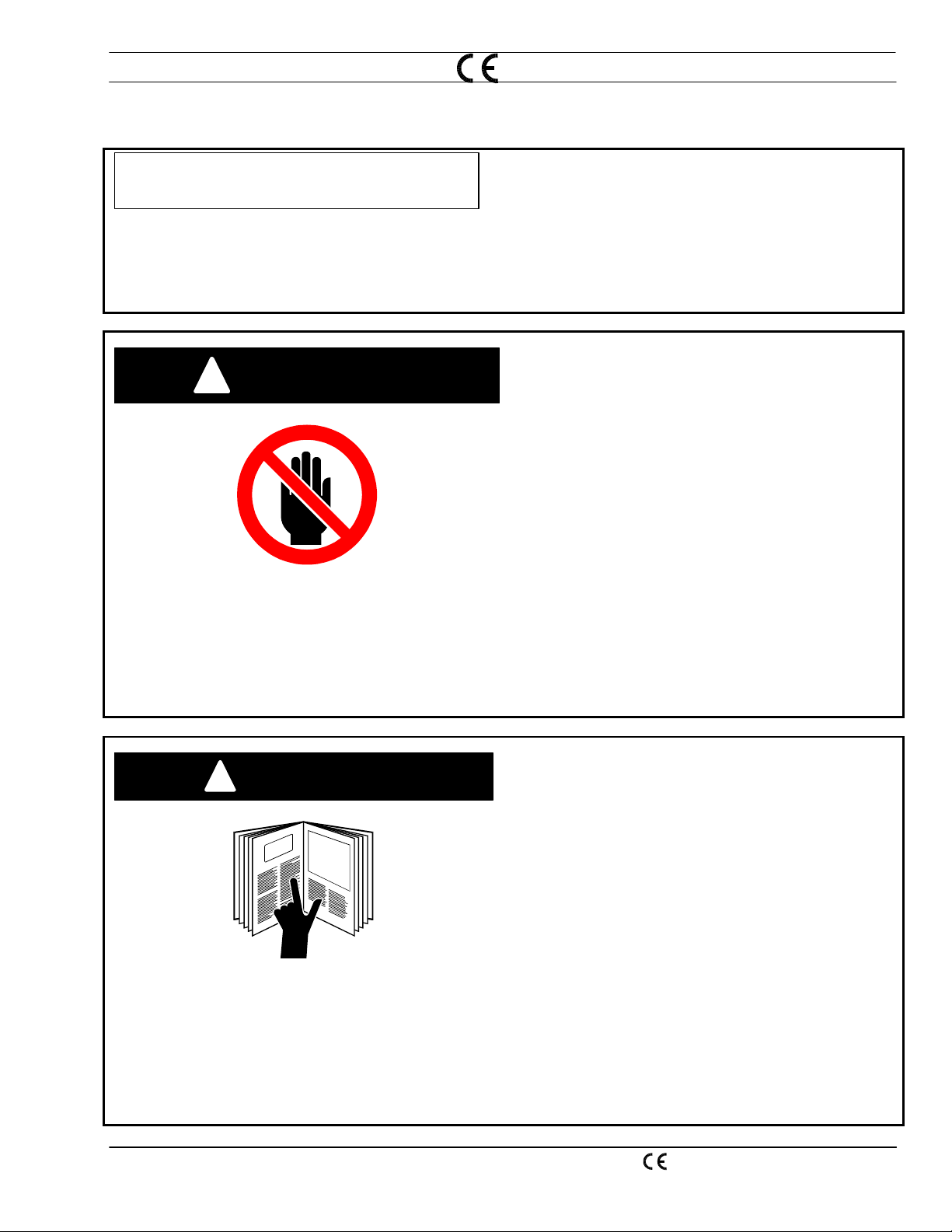
Failure to follow operating instructions
WARNING
!
could result in death or serious injury.
Read and understand this operator’s manual before
using machine.
· Read entire procedure before operating or
performing any system maintenance.
· Special attention must be given to all hazard
warnings that provide essential information
regarding personnel safety and/or possible
equipment damag e.
· All safety precautions relevant to electrical
equipment and process operation s mu s t be
strictly observed by all having system
responsibility or access.
· Read all safety publications made available by
your company.
PT-24 Precision Plasma System IEFC -S -
1-3
Page 12

SECTION 1 SAFETY
Failure to follow safety warning label
WARNING
!
1.4 Installation Precautions
instructions could result in death or
serious injury.
Read and understand all safety warning labels on
machine.
Refer to operator’s manual for additional safety
information.
WARNING
!
Improperly Installed Equipment Can Cause
Injury Or Death.
Follow these guidelines while installing ma chine:
· Do not connect a cylinder directly to machine inlet.
An appropriate cylinder regulator must be installed
on a fuel gas cylinder to reduce pressure to a
reasonable inlet supply pressure. Machine
regulator is then used to obtain pressure required
by torches.
· Contact you r ESAB representative before
installation. He can suggest certain precautions
regarding piping installation and machine lifting,
etc. to ensure maximum security.
· Never attempt any machine modifications or
apparatus additions without first consulting a
qualified ESAB representative .
· Observe ma ch in e clearance requirement s for
proper operation and personnel safety.
· Always have qualified personnel perform
installation, troubleshooting and maintenance of
this equipment.
1-4
· Provide a wall mounted disconnect switch with
proper fuse sizes close to the power supply.
PT-24 Precision Plasma System IEFC -S -
Page 13

SECTION 1 SAFETY
1.5 Electrical Grounding
Electrical grounding is imperative for proper machine
operation and SAFETY. Refer to this manual’s
Installation section for detailed grounding instructions.
Electric shock hazard.
WARNING
!
Improper grounding can cause severe injury or death.
Machine must be properly grounded before put into
service.
Improper Grounding Can Damage
WARNING
!
Machine And Electrical Components.
· Machine must be properly grounded before put
into service.
· Cutting table must be properly grounded to a good
Earth ground rod.
PT-24 Precision Plasma System IEFC -S -
1-5
Page 14

SECTION 1 SAFETY
1.6 Operating A Plasma Cutting Machine
WARNING
!
WARNING
!
Flying debris and loud noise hazards.
· Hot spatter can burn and injure eyes. Wear
goggles to protect eyes from burns and flying
debris generated during operation.
· Chipped slag may be hot and fly far. Bystanders
should also wear goggles and safety glasses.
· Noise from plasma arc can damage hearing. Wear
correct ear protection when cutting above water.
Burn hazard.
Hot metal can burn.
· Do not touch metal plate or parts immediately after
cutting. Allow metal time to cool, or douse with
water.
· Do not touch plasma torch immediately after
cutting. Allow torch time to cool.
1-6
PT-24 Precision Plasma System IEFC -S -
Page 15

SECTION 1 SAFETY
WARNING
!
Hazardous voltages. Electric shock
can kill.
· Do NOT touch plasma torch, cutting table or cable
connections during plasma cutting process.
· Always turn power off to plasma power supplies
before touching or servicing plasma torch.
· Always turn power off to plasma power supplies
before servicing any system component.
· Do not touch live electrical parts.
· Keep all panels and covers in place when machine
is connected to power source.
· Wear insulating gloves, shoes and clothing to
insulate yourself from workpiece and ele ctr ic al
ground.
· Keep gloves, shoes, clothing, work area, and
equipment dry.
·
Replace worn or damaged cables.
Fume hazard.
WARNING
!
Fumes and gases generated by the plasma cutting
process can be hazardous to your heal th.
· Do NOT breathe fumes.
· Do not operate plasma torch without fume removal
system operating properly.
· Use additional ventilation to remove fumes if
necessary.
· Use approved respirator if ventilation is not
adequate.
·
Provide positive mechani cal ven t ilation when
cutting galvanized steel, stainless steel, copper,
zinc, beryllium, or cadmium. Do not breathe these
fumes.
·
Do not operate near degreasing and spraying
operations. Heat or arc rays can react with
chlorinated hydrocarbon vapors to form phosgene,
a highly toxic gas and other irritant gases.
PT-24 Precision Plasma System IEFC -S -
1-7
Page 16

SECTION 1 SAFETY
WARNING
Radiation hazard.
!
Arc rays can in j u re eyes and burn sk i n.
· Wear correct eye and body protection.
· Wear dark safety glasses or goggles with side
shields. Refer to following chart for recommended
lens shades for plasma cutting:
Arc Current Lens Shade
Up to 100 Amps Shade No. 8
100-200 Amps Shade No. 10
200-400 Amps Shade No. 12
Over 400 Amps Shade No. 14
· Replace glasses/goggles when lenses are pitted or
broken
· Warn others in area not to look directly at the arc
unless wearing appropriate safety glasses.
· Prepare cutting area to reduce reflection and
transmission of ultraviolet light.
§ Paint walls and other surfaces with dark
colors to reduce reflections.
§ Install protective screens or curtains to
reduce ultraviolet transmission.
WARNING
!
Ruptured Gas Cylinders Can Kill
Mishandling gas cylinders can rupture and violently
release gas.
· Avoid rough handling of cylinders.
· Keep cylinder valves closed when not in use.
· Maintain hoses and fittings in good condition.
· Always secure cylinders in an upright position by
chain or strap to a suitable stable object not part of
an electrical circuit.
· Locate cylinders away from heat, sparks and
flames. Never strike an arc on a cylinder.
· Use ap proved pressure redu cing regulator for t h e
specific gas.
· Refer to CGA Standard P-1, “Precautions for Safe
Handling of Compressed Gases in Cylinders”,
available from Compressed Gas Association.
1-8
PT-24 Precision Plasma System IEFC -S -
Page 17

SECTION 1 SAFETY
WARNING
Burn Hazard.
!
Heat, spatter, and sparks cause fire and burns.
· Do not cut near combustible material.
· Do not have on your person any combustibles (e.g.
butane lighter).
· Pilot arc can cause burns. Keep torch nozzle
away from yourself and others when activating
plasma process.
CAUTION
· Wear correct eye and body protection.
· Wear gauntlet gloves, safety shoes and hat.
· Wear flame-retardant clothing covering all exposed
areas.
· Wear cuff-less trousers to prevent entry of sparks
and slag.
· Have fire extinguishing equipment available for use.
Do Not Use this Torch Under Water.
The PT-24 is designed to be a dry cutting
process.
Cutting under water may result in:
· reduced consumable life
· degradation of cut quality
· possible damaged torch
Cutting under water may result in poor cutting
performance. Water vapor created when hot material
or sparks contact liquid may cause arcing inside torch.
When cutting on a w ater table, reduce the water le vel
to provide maximum clearance between water and
material.
PT-24 Precision Plasma System IEFC -S -
1-9
Page 18

SECTION 1 SAFETY
WARNING
!
WARNING
!
Explosion hazard.
· Certain molten aluminum-lithium (Al-Li) alloys can
cause explosions when plasma cut OVER water.
§ These alloys should only be dry cut on a dry
table.
§ DO NOT dry cut over water.
§ Contact your aluminum supplier for
additional safety information regarding
hazards associated with these alloys
Do not cut in atmospheres containing explosive
·
dust or vapors.
·
Do not carry any combustibles on your pers on
(e.g. butane lighter)
· Do not cut containers that have held combustibles.
.
Pinch hazard.
Moving vertical slides can crush or pinch.
Keep hands clear of torch and slide during operation.
1-10
PT-24 Precision Plasma System IEFC -S -
Page 19

SECTION 1 SAFETY
1.7 Service Precautions
WARNING
!
Hazardous voltages. Electric shock
can kill.
· Do NOT touch plasma torch, cutting table or cable
connections during plasma cutting process.
· Always turn power off to plasma power supplies
before touching or servicing plasma torch.
· Always turn power off to plasma power supplies
before removing covers or panels to service any
system component.
· Do not touch live electrical parts.
· Keep all panels and covers in place when machine
is connected to power source.
· Keep gloves, shoes, clothing, work area, and
equipment dry.
·
Inspect power and ground leads cables for wear or
cracking. Replace worn or damaged cables. Do
not use if damaged.
·
Never bypass safety interlocks.
Follow lock-out procedures.
·
Establish and adhere to preventive maintenance. A
CAUTION
CAUTION
!
composite program can be establishe d from
recommended schedules.
Avoid leaving test equipment or hand tools on
machine. Severe electrical or mechanical damage
could occur to equipment or machine.
Extreme caution should be used when probing
circuitry with an oscilloscope or voltm eter. Integrat ed
circuits are susceptible to over voltage damage.
Power off before using test probes to prevent
accidental shorting of components.
All circuit boards securely seated in sockets, all cables
properly connected, all cabinets closed and locked, all
guards and covers replaced befo re power is turned
on.
PT-24 Precision Plasma System IEFC -S -
1-11
Page 20

SECTION 1 SAFETY
1.8 Safety References
Domestic
The following nationally recognized publications on
safety in welding and cutting operations are
recommended. These publications have been
prepared to protect persons from injury or illness and
to protect property from damage, which could result
from unsafe practices. Although some of these
publications are not related specifically to this type of
industrial cutting apparatus, the principles of safety
apply equally.
· “Precautions and Safe Practices in Welding and Cutting with
Oxygen-Fuel Gas Equipment,” Form 2035. ESAB Cutting
Systems.
· “Precautions and Safe Practices for Electric Welding and Cutting,”
Form 52-529. ESAB Cutting Systems.
· “Safety in Welding and Cutting” - ANSI Z 49.1, American Welding
Society, 2501 NW 7th Street, Miami, Florida, 33125.
· “Recommended Safe Practices for Shielded Gases for Welding and
Plasma Arc Cutting” - AWS C5.10-94, American Welding Society.
· “Recommended Practices for Plasma Arc Welding” - AWS C5.1,
American Welding Society.
· “Recommended Pract i ces for Arc Cutting” - AWS C5.2, American
Welding Society.
· “Safe Practices” - AWS SP, American Welding Society.
· “Standard for Fire Protection in Use of Cutting and Welding
Procedures” - NFPA 51B, National Fire Protection Association, 60
Batterymarch Street, Boston, Massachusetts, 02110.
· “Standard for Installation and Operation of Oxygen - Fuel Gas
Systems for Welding and Cutting” - NFPA 51, National Fire
Protection Association.
· “Safety Precautions for Oxygen, Nitrogen, Argon, Helium, Carbon
Dioxide, Hydrogen, and Acetylene,” Form 3499. ESAB Cutting
Systems. Obtainable through your ESAB representative or local
distributor.
· "Design and Installation of Oxygen Piping Systems," Form 5110.
ESAB Cutting Systems.
· “Precautions for Safe Handling of Compressed Gases in
Cylinders”, CGA Standard P-1, Compressed Gas Association.
Literature applicable to safe practices in welding and cutting with
gaseous materials is also available from the Compressed Gas
Association, Inc., 500 Fifth Ave., New York, NY 10036.
1-12
PT-24 Precision Plasma System IEFC -S -
Page 21

SECTION 1 SAFETY
International
Accident Prevention
VBG- Unfallverhütungsvorshriften
General Provisions
VBG 1
Allgemeine Unfallverhütungsvorshriften
Electrical Equipment and operating Equipment
VBG 4
Elektrische Anlagen
Welding, Cutting and related working methods
VBG 15
Schweißen un Schneiden un verwandte Verfahren
Shot Blasting Works
VBG 48
Strahlarbeiten
Gases
VBG 61
Gase
Oxygen
VBG 62
Sauerstoff
Operating liquid jet cutting machines
VBG 87
Arbeiten mit Flüssigkeitsstrahlem
VBG 93
Laser beams, accident prevention and Electrotechnology
Laserstrahlung, Unfallverhütungs-vorschriften für
Feinmechnik und Elektrotechnik
Noise
VBG 121
Lärm
PT-24 Precision Plasma System IEFC -S -
1-13
Page 22

SECTION 1 SAFETY
VDE Regulations
VDE - Vorschriften
VDE 0100
Erection of power installations with normal voltages up to
1000 volts
Bestimmungen für das Errichten von Stakstromanlagen
mit Nennspannungen bis 1000 Volt
Electrical equipment of industrial machines
VDE0113
VDE 0837
VDE 0837-
50
Elektrishe Ausrüstung von Industriemaschinen
Radiation safety of laser products; users guide (DIN EN
60825)
Strahlungssicherheit von Lasereinrichtungen und
Benutzungsrichtlinen (DIN EN 60825)
Specification for laser guards
Anforderung an Lasershcutzwänden
TRAC Technical Rules for Acetylene and Carbide Stores
TRAC- Techische Regein für Azetylenanlagen und Calciumcargidlager
Acetylene lines
TRAC-204
Azetylenleitungen
Acetylene cylinder battery systems
TRAC-206
Azetylenflaschenbatterieanlagen
Safety devices
TRAC-207
Sicherheitseinrichtungen
TRG Technical Rules for Pressure gases
TRG – Technische Regein für Druckgase
TRG 100
TRG 101
TRG 102
TRG 104
1-14
PT-24 Precision Plasma System IEFC -S -
General regulations for pressure gases
Allgemeine Bestimmungen für Druckgase
Pressure gases
Druckgase
Technical gas mixtures
Technishe Gasgemische
Pressure gases; alterative use of compressed gas tanks
Druckgase, wahlweise Verwendung von
Druckgasbehältem
Page 23

SECTION 1 SAFETY
TRGS – Technische Richtlinien für Gefahrstoffe
TRGS-102 Techn. Richtkonzentration (TRK) für gefährliche Stoffe
DIN Standards
DIN-Normen
TRGS-402
TRGS-900 Grenzwerte in der Luft am Arbeitsplatz (Luftgrenzwerte)
TA TA-Luft un TA-Lärm (BLm SchV)
DIN 2310
Part 1
Teil 1
DIN 2310
Part 2
Teil 2
DIN 2310
Part 4
Teil 4
DIN 2310
Part 5
Teil 5
DIN 2310
Part 6
Ermittlung u. Beurteilung der Konzentration gefährlicher
Stoffe in der Luft im Arbeitsbereich
Thermal cutting; terminology and nomenclature
Thermsiches Schneiden, Allgemeine Begriffe und
Bennungen
Thermal cutting; determination of quality of cut faces
Thermsiches Schneiden, Ermittein der Güte von
Schnittflächen
Thermal cutting; arc plasma cutting; process principles,
quality, dimensional tolerances
Thermsiches Schneiden, Plasmaschneiden,
Verfahrensgrundlagen, Güte, Maßtoleranzen
Thermal cutting; laser beam cutting of metallic materials;
process principles
Laserstrahlschneiden von metallischen Werkstoffen,
Verfahrensgrundlagen, Güte, Maßtoleranzen
Thermal cutting; Classification, processes
Teil 6 Einführung, Verfahren
DIN 4844
Part 1
Teil 1 Sicherheitskennzeichen (Siehe EN 7287)
PT-24 Precision Plasma System IEFC -S -
Safety markings (DIN EN 7287)
1-15
Page 24

SECTION 1 SAFETY
DIN EN ISO Harmonized Standards
DIN EN ISO-Harmonisierte Normen
DIN EN
292/1 and 2
DIN EN 559
DIN EN 560
DIN EN 561
DIN EN
626-1
DIN EN
848-1
Safety of machinery
Sicherheit von Maschinen, Geräten und Anlagen
Hoses for welding, cutting and allied processes
Schläuche für Schweißen, Schneiden und verwandte
Verfahren
Hose connections and hose couplings for equipment for
welding, cutting and allied processes
Schlauchanschlüsse und Schlauchverbindungen für
Geräte zum Schweißen, Schneiden und verwandte
Verfahren
Gas welding equipment hose couplings
Gasschweißgeräte, Kupplungen
Safety of machines, reduction of risks to health
Sichereit von Maschinen, Reduzierung des
Gesundheitsrisikos
Single spindle vertical milling machines
Fräsmaschine für einseitige Bearbeitung mit drehendem
Werkzeug
DIN EN
1829
DIN EN
9013
DIN EN
12584
DIN EN
12626
DIN EN
28206
DIN EN
31252
High pressure water jet machines
Hochdruckwasserstrahlschneidmaschine
Thermal cutting, oxygen cutting, process principles,
dimensional tolerances
Thermisches Schneiden, Autogenes Brennschneiden,
Verfahrensgrundlagen, Güte, Maßtoleranzen
Imperfections in oxy/fuel flame cuts, laser beam cuts and
plasma
Unregeimäßigkeiten an Brennschnitten, Laserstrahl- und
Plasmaschnitten
Laser processing machines
Laserbearbeitungsmaschinen
Acceptance testing for oxygen cutting machines
Abnahmeprüfung für Brennschneidmaschinen
Laser Equipment
Lasergeräte
1-16
PT-24 Precision Plasma System IEFC -S -
Page 25

SECTION 1 SAFETY
VDI Guidelines
DIN EN
31553
DIN EN
60204-1
DIN EN
60825
DIN EN 999
VDI 2906
VDI 2084
Laser and laser related equipment
Laser und Laseranlagen
Electrical equipment of machines
Elekrische Ausrüstung von Maschinen
Radiation safety of laser products
Strahlensicherheit von Laseranlagen
Arrangement of protection devices
Anordnung von Schutzeinrichtungen
Quality of cut faces on metallic workpieces; abrasive
water jet cutting and arc plasma cutting
Schnittflächenqualität beim Schneiden von Werkstücken
aus Metall, Abrasiv- Wasserstrahischneiden und
Plasmastrahischneiden
Room air; Technical systems for welding workshops
Raumluft techn. Anlagen für Schweißwerkstätten
PT-24 Precision Plasma System IEFC -S -
1-17
Page 26

SECTION 1 SAFETY
This page intentionally left blank.
1-18
PT-24 Precision Plasma System IEFC -S -
Page 27

SECTION 2 DESCRIPTION
2.1 General
2.2 Scope
The PT-24 Precision Plasmarc IEFC-S System
provides programmable gas switching and pressure
control. The IEFC-S is the third generation
electronic flow control for the ESAB 100A precision
plasma system. Advantages over the original
electronic flow control are:
• reduced combined footprint over the original
design
• fewer parts
• improved reliability
• improved high speed switch-over marking
option
While using the same highly reliable integrated
design and components, the gas and ignition
consoles have been separated to two enclosures.
The gas and ignition consoles can be bolted as a
combined unit or separated to allow the ignition
console to be placed closer to the torch. This new
design allows maximum component locating
flexibility.
The gas pressure and switching is controlled
through the cutting machine CNC eliminating the
need for other programmable controls.
The purpose of this manual is to provide the
operator with all the information required to install
and operate the Precision Plasmarc System.
Technical reference material is also provided to
assist in troubleshooting the cutting package.
PT-24 Precision Plasma with IEFC-S Consoles
2-1
Page 28

SECTION 2 DESCRIPTION
2.3 Package Options Available
Precision Plasmarc® IEFCS package options available through your ESAB dealer
Precision Plasmarc® Power Console (200/230/380/415/460/575) 3-phase 50/60 Hz
(required) CNC Controllable/Without PLC CE Version (covered in this manual) P/N 0558002263
Gas Console P/N 0558003641
Ignition Console P/N 0558003640
4.5 ft. (1.4 m) P/N 0558002337
PT-24 Torch with high speed marking
Power Bundle (one required)
Interconnection Bundle
Control Lead, CNC to Power Supply (one required)
Torch Coolant (one gallon (3.8 liters) containers. four gallons (15 liters) required) P/N 156F05
NOTES:
• Interconnection Bundle is only required if Gas Console and Ignition Console are separated. See
Interconnection Diagram in section 3.
• Control lead from the power source to customer CNC is supplied based on customer order.
• Gas supply, hoses, work lead and input primary cable are all supplied by the customer.
• See Process Data Sheets for a list of torch consumable parts.
12 ft. (3.7 m) P/N 0558002338
20 ft. (6.1 m) P/N 0558002339
12 ft. (3.7 m) P/N 22428
25 ft. (7.6 m) P/N 21905
40 ft. (12.2 m) P/N 22504
60 ft. (18 m) P/N 21906
80 ft. (24.4 m) P/N 22505
100 ft. (30 m) P/N 21907
10 ft. (3 m) P/N 0558003642
20 ft. (6 m) P/N 0558003643
30 ft. (9 m) P/N 0558003644
10 ft. (3 m) P/N 0560987422
20 ft. (6.1 m) P/N 0560987423
30 ft. (9 m) P/N 0560987424
60 ft. (18 m) P/N 0560987425
100 ft. (30 m) P/N 0560987426
2-2
PT-24 Precision Plasma with IEFC-S Consoles
Page 29

SECTION 2 DESCRIPTION
2.4 Precision Plasma Technical Specifications
2.4.1 System
Input Voltage 200/230/380/415/460/575 V 3 phase 50/60 Hz
Input Current 65/60/50/40/30/25 amps per phase
Power Factor 0.95
Output Current Range 15-100 amps dc
Output Load Voltage 215 Vdc
Duty Cycle 100%
Open Circuit Voltage 315 V dc
1118mm
Power Console
PT-24 Torch with
Manifold
1067mm
559mm
200mm
191mm
191mm
Ignition Console
369mm
PT-24 Precision Plasma with IEFC-S Consoles
369mm
Gas Console
289mm
2-3
Page 30

SECTION 2 DESCRIPTION
2.4.2 Plasma Gas Technical Specifications
Type O
Pressure
, N2, Ar, Air
2
150 psig (10.4 bars) O2, N2, Air: 85 psig (5.9 bars) Ar
Flow 100 cfh (47 l/min) max. (varies with application)
O
-99.8 to 99.995% N2, Ar-99.995%
Purity Required*
Recommended Liquid Cylinder Service
Regulators
2
Air-clean, dry and oil free
Oxygen: R-76-150-540LC (P/N 19777)
Inert gas: R-76-150-580LC (P/N 19977)
Oxygen: R-77-150-540 (P/N 998337
Recommended Cylinder 2-Stage
Regulators
Hydrogen/Methane:R-77-150-350 (P/N 998342)
Nitrogen: R-77-150-580 (P/N 998344)
Industrial Air: R-77150=590 (P/N 998348)
Recommended Heavy –Duty Hi-flow
Station or Pipeline Regulators
Recommended High-capacity Station
or Pipeline Regulators
Oxygen: R-76-150-024 (P/N 19151)
R-6703 (P/N 22236)
Gas Filter Required 25 micron w/bowl guard (P/N 56998133)
2.4.3 Start Gas Technical Specifications
Type N
Pressure
Flow 60 cfh (28 l/min) max (varies with application)
Minimum Purity Required N2, Ar - 99.995% Air –Clean, Dry
, Ar, Air
2
150 psig (10.4 bars) N2, Air: 85 psig (5.9 bars) Ar
2.4.4 Secondary Gas Technical Specifications
Type N2, O2, Methane, Air
Pressure
100 psig (6.6 bar) H-35, Methane;
150 psig (10.4 bar) N
, O2, Air
2
Flow 60 cfh (28 l/min) max (varies with application)
Minimum Purity Required N2, O2, CH4 - 99.995% Air –Clean, Dry
2.4.5 Cut Gas Technical Specifications
Type N2, O2, Air
Pressure 150 psig (10.4 bar) N2, O2, Air
Flow 60 cfh (28 l/min) max (varies with application)
Minimum Purity Required 99.995% N2, 99.8% O
and Air- clean and dry
2
2.4.6 Pt-24 Torch Technical Specifications
Type Water-Cooled, Dual Gas
Rating 100 amps @ 100 % duty cycle
Dimensions See Package Options (2.3)
2-4
PT-24 Precision Plasma with IEFC-S Consoles
Page 31

SECTION 3 INSTALLATION
3.1 General
NOTICE
Proper installation can contribute materially to
the satisfactory and trouble-free operation of the
Precision Plasmarc® System. It is suggested
that each step in this section be studied and
carefully followed.
3.2 Equipment Required
3.3 Location
· Gas Supply and Hoses. Gas supply may be from
a bulk source or from a bank of manifold cylinders
and regulated to supply 150 psig (10.4 bar) to the
gas console (gas flowing).
· Work Lead. No. 4 AWG cable is recommended for
connecting workpiece to power source.
· Primary Input Cable.
· 25 micron gas filters (P/N 56998133) are required
on the supply side for the IEFC-S to function
properly.
· Ventilation is necessary to provide proper cooling
of the power supply.
· Minimize dirt, dust and exposure to external heat
sources.
3-1
· Allow a minimum of two feet clearance around the
power supply for free air movement.
Restricting Air Flow Will Cause Over-Heating
CAUTION
!
PT-24 Precision Plasma with IEFC-S Consoles
Restricting intake air with any type of filter on or
around the power supply will cause over-heating
and void the warranty.
Page 32

SECTION 3 INSTALLATION
3.4 Primary Electrical Input Connections
Electric Shock Can Kill!
DANGER
!
Provide maximum protection against electrical
shock.
Before any connections are made inside the
machine, open the line (wall) disconnect switch
and unplug the power cord.
WARNING
!
Input Power Configuration
Machine must be properly configured for your
input power.
The machine is shipped from the factory
configured for 575 V, 60 Hz input.
Do NOT connect a power source of any other
voltage unless machine is reconfigured. Damage
to the machine wil l occur.
208 3 70 No. 4 25 100
230 3 60 No. 6 16 80
380 3 50 No. 8 10 80
415 3 40 No. 10 6 60
460 3 30 No. 10 6 50
575 3 25 No. 10 6 40
Input Power Connection At Wall
A line (wall) disconnect switch with fuses or circuit
breakers should be provided at the main power panel.
Connect the input power cable of the power source
directly to the disconnect switch or a proper plug and
receptacle may be purchased from a local electrical
supplier. (See table on the next page for
recommended input conductors and fuses )
Recommended Sizes For Input Conductors And Line Fuses
Input requirements
Volts Phase Amps
Input & ground
conductor,
cu/awg/mm
2
Fuse ratings /
phase, amps
3-2
PT-24 Precision Plasma with IEFC-S Consoles
Page 33

SECTION 3 INSTALLATION
The following procedure explains the proper installation
steps for connecting primary electrical power to the
power source.
1. Remove right side panel.
2. Ensure input power cable is disconnected from all
electrical sources.
3. Route input power cable through the strain relief
located at the rear panel.
TB2
TB1
200
230
380
415
460
575
Ground
Connection
K1
PHASE 1 PHASE 2 PHASE 3
200
230
380
415
460
575
200
230
380
415
460
575
200
230
380
415
460
575
Input Power
Cable
Main
Contactor
7 position
Termainal Block
Auto Transformer
4. Pull input power cable through the strain relief to
allow cable wires sufficient length to connect to the
main contactor. Tighten strain relief to ensure
input power cable is secured.
5. Connect input power cable ground wire to the
ground lug provided on the base of the power
source.
6. Connect three power leads of the input power
cable to the terminals located atop the main
contactor. Secure the leads by tightening each
screw.
7. Connect jumper power cables from the bottom of
the main contactor to the proper input voltage
marked on the auto transformer. The unit is
factory set for 575 V as shown to the left.
Factory Wired
for 575 Volts
3-3
CAUTION
!
Input Power Jumper Connection
Ensure each input power jumper cable is
connected to the correct input voltage on auto
transformer.
Factory wired for 575 V.
8. Connect jumper wire to the proper input voltage
connector located on the 7-position terminal block.
TB2
PT-24 Precision Plasma with IEFC-S Consoles
Page 34

SECTION 3 INSTALLATION
3.5 Alternate Connection Locations For IEFC-S Gas Console
There are two locations for the torch strain relief in
the ignition console. This provides flexibility while
mounting the box to a machine.
NOTE:
When changing over to an alternate
connection location, plug unused I/O strain
relief holes to seal box.
Torch Strain Relief Alternate Location for
Torch Strain Relief
3.6 Gas Console Basic Component Identification And Connection Points (Cover Removed)
ASIOB Connection Process ASIOB
P-5 Connection
P-1 115/230V In
24VAC In
P-2 Desired Current
Value (not shown)
Voltage Selector
Switch
Gas Supply In Proportional Valves
Solenoids
Gas Supply In
Manifold
Gas Output (not shown)
3-4
PT-24 Precision Plasma with IEFC-S Consoles
Page 35

SECTION 3 INSTALLATION
3.7 Ignition Console Basic Components and Connections Points
Pilot Arc Strain Relief
Alternate Torch
Bundle Strain
Relief Location
Cooling Water to
Torch/Arc Current
Cooling water from
Torch/Pilot Arc
Spark Gap Adjustment
Torch Bundle Strain
Relief
Chassis Ground
H.F. 120V Input
Torch Power Strain
Relief
Cooling Water
To/From Power
Console Fittings
(not shown)
3-5
PT-24 Precision Plasma with IEFC-S Consoles
Page 36

SECTION 3 INSTALLATION
3.8 Interconnecting Lines
2
1
3
1
4
2
Torch Bundle
All interconnecting service lines supplied are labeled
or color coded on each end with corresponding
labels/colors marked on the cabinets.
COOLING WATER TO TORCH/ARC
1
2
3
4
CURRENT CABLE
COOLING WATER FREOM TORCH/ PILOT
ARC CABLE
TORCH BUNDLE GAS LINES
P-2 SOLENOID CONTROL CABLE
1. Connect lines in torch bundle to ignition
console. Lines and connections are labeled
and/or color coded.
Joined Gas and Ignition
Consoles
4
3
Interconnect Bundle
(connecting Gas and
Ignition Consoles when not
joined.)
View of inside ignition console will be the same if the
gas and ignition consoles are combined or
separated.
The interface plate of the interconnect bundle is
configured identically to the gas/signal output of the
gas console.
3-6
PT-24 Precision Plasma with IEFC-S Consoles
Page 37

SECTION 3 INSTALLATION
3.9 Joining Ignition and Gas Consoles to Form One Unit
Remove black button head filler screws from
mating faces of the consoles. Some of these
screws are captured with hex nuts from the inside
of the gas console.
Remove top covers. These are held on with ¼ turn
quick release fasteners.
Remove these screws from mating faces.
The gas console output connections (and P5) are
designed to fit into cutouts in the ignition console
allowing the two faces to mate flush.
Use filler screws previously removed to fasten
consoles together. Most screw positions, screws
will pass through a clearance hole in the gas
console to be threaded into a pressed cap nut in
the ignitions console. There may be a few
exceptions.
3-7
View of joined consoles from inside ignition
console
PT-24 Precision Plasma with IEFC-S Consoles
Page 38

SECTION 3 INSTALLATION
3.10 Connecting Separated Gas and Ignition Consoles
An interconnect bundle is required to connect
separated consoles
Gas console connections. Hoses/cables and fixed
fittings are labeled.
Ignition Console Interface Bundle
Faceplate
Fasten faceplate to the ignition console using 4
screws provided.
View inside Ignition console with face plate
attached.
3-8
PT-24 Precision Plasma with IEFC-S Consoles
Page 39

SECTION 3 INSTALLATION
3.11 Power Console Connections
Power Supply Bundle
Input Power Strain
Relief
Cooling Water In/Out
3.12 Voltage Selector Switch
Voltage
Selector
Switch
2. Connect power and coolant lines in Power
Supply Bundle from power console to ignition
console. Power bundle consists of #6 and # 7
coolant lines (with 5/8-18 L.H. fittings), power
cable (#3 AWG) and yellow pilot arc cable (#16
AWG). Coolant lines are stamped with a 6 or 7
on the fitting to assist in identification.
Voltage selector switch inside the gas console is
preset for IEFC-S input voltage of 115 V / 60 Hz
applications. An alternate setting accommodates
230 V / 50 Hz IEFC-S input voltage.
3-9
PT-24 Precision Plasma with IEFC-S Consoles
Page 40

SECTION 3 INSTALLATION
3.13 Precision Plasmarc® Separated Gas and Ignition Console Component
Interconnecting Diagram
9
11
12
8
10
20
7
6
5
13
14
16
15
21
17
22
4
3
2
3-10
18
19
Ar
O
CH
N
4
2
2
Air
PT-24 Precision Plasma with IEFC-S Consoles
1
Page 41

SECTION 3 INSTALLATION
1 wall disconnect (cust. sup.)
2 primary power cable
3 precision plasma power console
4 power bundle
5 power supply I/O cable
6 earth ground
7 work cable (+)
8 torch and height control
9 height control I/O cable
10 torch bundle
11 height control ASIOB enclosure
12 ignition console
13 height control ASIOB cable*(see note)
14 process ASIOB cable
15 120 vac/24vdc cable
16 CNC
17 process gas lines
18 25 micron filters
19 process gas supply (cust. sup.)
20 cutting table
21 Interconnecting Console Bundle
22 Gas Console
Note: #13 height control ASIOB cable comes from a junction with #14 process ASIOB cable inside the IEFC-S.
3-11
PT-24 Precision Plasma with IEFC-S Consoles
Page 42

SECTION 3 INSTALLATION
3.14 Precision Plasmarc® Combined Gas and Ignition Console Component
Interconnecting Diagram
9
11
8
10
20
7
13
14
12
6
5
4
22
3
15
3-12
16
17
2
18
19
Ar
O
CH
N
4
2
2
Air
PT-24 Precision Plasma with IEFC-S Consoles
1
Page 43

SECTION 3 INSTALLATION
1 wall disconnect (cust. sup.)
2 primary power cable
3 precision plasma power console
4 power bundle
5 power supply I/O cable
6 earth ground
7 work cable (+)
8 torch and height control
9 height control I/O cable
10 torch bundle
11 height control ASIOB enclosure
12 ignition console
13 height control ASIOB cable*(see note)
14 process ASIOB cable
15 120 vac/24vdc cable
16 CNC
17 process gas lines
18 25 micron filters
19 process gas supply (cust. sup.)
20 cutting table
21 interconnecting Console Bundle (not shown -- not required when consoles are combined)
22 Gas Console
Note: #13 height control ASIOB cable comes from a junction with #14 process ASIOB cable inside the IEFC-S.
3-13
PT-24 Precision Plasma with IEFC-S Consoles
Page 44

SECTION 3 INSTALLATION
3.15 Input To Gas Console
Gas Line Contamination Will
CAUTION
!
Damage Proportional Valves And
Check Valves
Purge Gas Lines
Before connecting gas delivery lines to the
Integrated Flow Control, purge all lines
thoroughly. Residue from the hose
manufacturing process may clog/damage the
proportional valves in your flow control.
1. Purge gas lines between supply and the IEFCS before connecting. Proportional and check
valves are very sensitive to dust and other foreign
particles.
CAUTION
!
Unfiltered Gases Will Damage Flow
Control System.
Unfiltered cut and shield gases will clog or
damage small orifices and gas seals.
25µ filters are required for all cut and
shield gases including nitrogen, oxygen,
argon, methane, and air.
3-14
PT-24 Precision Plasma with IEFC-S Consoles
Page 45

SECTION 3 INSTALLATION
Gas Console Input
1/4 NPT
25 micron gas filter
2. Connect gas delivery lines to integrated flow
control. Install 25 micron gas filters in all delivery
lines between gas source and gas console.
3-15
CH
25 micron filters
Ar
O
4
2
2
N
H-35
Air
PT-24 Precision Plasma with IEFC-S Consoles
Page 46

SECTION 3 INSTALLATION
3.16 Input to Power Console
CAUTION
Pilot Arc
Work
Torch
Remove cover
Proportional And Check Valves Are
Sensitive To Dirt And Debris.
Thoroughly purge the gas delivery system with
before connecting to the gas console. Hose
N
2
manufacturing often leaves a fine dust inside.
This dust may cause proportional valves to
prematurely fail. Check valves may become
clogged.
P
Input Strain Relief
7 Amp 500VAC
Fuse
Rating
Lable
Flow Control
Lead
1. Remove panel from rear of console and attach
the pilot-arc, torch and work lead.
2. Connect power supply I/O cable between the
console and the CNC.
Serial
Tag
Cooling Water In
Cooling Water Out
3-16
From Ignition Console
PT-24 Precision Plasma with IEFC-S Consoles
Page 47

SECTION 3 INSTALLATION
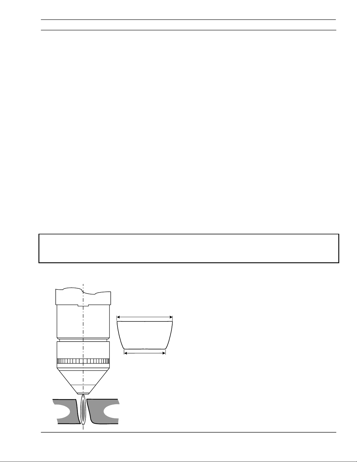
3.17 Torch Mounting
CAUTION
Do Not Cover Vent Hole.
When mounting, do not to cover the small vent
hole in the side of the sleeve. This hole allows
coolant to drain from inside the sleeve should a
leak occur in a service line.
Torch Mounting Options.
1.812" (46mm)
Diameter Collar
2.0
" (51mm)
Diameter Sleeve
Vent Hole
· The torch is normally mounted by the 2.0 inch
diameter (51mm) sleeve. Do not cover vent hole.
· For custom alternative mounting, the torch can be
mounted by the 1.812" (46 mm) dia collar shown.
This insulated collar and its shoulder are machined
relative to the nozzle retainer thread on the torch
body.
Use only specified mounting surfaces
3-17
PT-24 Precision Plasma with IEFC-S Consoles
Page 48

SECTION 3 INSTALLATION
3.18 Torch Coolant
L
O
T
R
N
O
C
T
N
E
R
U
R
C
L
P
N
O
I
S
I
C
E
R
E
R
W
O
P
C
R
A
M
S
A
· Remove coolant fill cap at front of console and fill
coolant tank with 4 gallons (15 liters) of plasma
coolant, P/N 156F05 (one gallon).
Coolant
Fill Cap
CAUTION
!
3.19 Inspection of Gas and Coolant Lines
· Do not fill above maximum level
· Reinstall Cap.
Commercial Antifreeze Will Cause
Torch To Malfunction
Use Special Torch Coolant! P/N156F05
Due to high electrical conductivity, DO NOT use
tap water or commercial antifreeze for torch
cooling. A specially formulated torch coolant is
REQUIRED. This coolant also protects for
freezing to –34° C.
Operating the unit without coolant will cause
permanent damage to the coolant pump.
3-18
To complete installation, it is necessary to inspect
field assembled connections for leaks.
· Gas lines, use a standard soap solution.
Pressurize the system from the control (SDP file)
· Coolant- check connections for signs of
moisture at connections
PT-24 Precision Plasma with IEFC-S Consoles
Page 49

SECTION 3 INSTALLATION
3.20 Using a 5 Solenoid Torch Manifold
The 5 solenoid torch manifold allows 1 second
conversion from cutting to marking and back to
cutting compared to 7 to 10 second switching
delay.
The IEFC-S is shipped configured to use the 5
solenoid torch manifold.
Marking with the PT-24 torch and the IEFC-
NOTICE
3.21 Converting IEFC-S Gas Console Manifold to Accommodate a 4 Solenoid Torch
Manifold
S does not utilize a proportional valve to
regulate Argon pressure. An external
regulator for the argon supply must be set
to 85 PSI (5,6 bar). See marking process
data for more information.
3
4
2
Gas Console Manifold
Argon inlet connection
1
Argon Solenoid
2
Marking Conversion Access 1/8 NPT
3
Air / Argon manifold outlet
4
1
a 5 solenoid torch. Some modification is required
to permit marking with the IEFC-S and a 4 solenoid
torch.
The gas console manifold is setup to accommodate
Ar
3-19
PT-24 Precision Plasma with IEFC-S Consoles
Page 50

SECTION 3 INSTALLATION
To plasma
gas outlet
From
argon solenoid
Cross Section Views of Argon Marking
Port
Plasma
View A-A
B
From
plasma gas
A
View B-B
B
Remove
access plug
to expose
port plug
A
Remove 1/16
NPT plug to
open Ar port
Marking Gas Solenoid
Gas Out
th
(5
Solenoid)
Procedure to modify IEFC manifold for 4 solenoid
torch manifold.
A. Locate and remove access plug (1/8 NPT) next
to the argon flow control solenoid as shown.
B. Remove port plug (1/16 NPT) from bottom of
inlet
access hole.
C. Replace access plug.
Note: If necessary, use a oxygen safe commercially
available pipe sealant. DO NOT USE Teflon Tape.
Pieces of tape may break free resulting in poor cut
quality or torch failure.
Schematic for Marking with IEFC and 4 Solenoid
torch manifold.
Proportional
Valve 1
Pressure
Vent
PS
Removable
Plug shown
removed
Switch 1
Air -2
N
-2
2
To Air-1
To N
-1 and
2
N
-3
2
Air In
Argon In
N2 In
With the plug installed and a 5 solenoid torch,
Argon gas goes directly to the 5
th
solenoid (Argon).
Argon is diverted across and out the plasma gas
line with the plug removed and a 4 solenoid torch.
The line to the fifth torch solenoid is capped with a
one way quick release fitting (acts similar to a check
valve)
3-20
PT-24 Precision Plasma with IEFC-S Consoles
Page 51

SECTION 4 OPERATION
4.1 Power Supply Controls
4.1.1 Main Power Switch
EMERGENCY
STOP
Main Power Switch
Controls the input power to the fan, water cooler and
the PC Board. Amber indicator light to the left of the
switch.
4.1.2 Pilot Arc Switch
Pilot Arc Switch
Previously a manual setting, This switch has been
eliminated from the CNC controllable power console.
Now handled by the machine CNC control to select
HIGH or LOW start pilot arc, depending on cutting
conditions. See Process Data for more information on
which conditions high and low start are used.
PT-24 Precision Plasma System IEFC-S 4-1
Page 52

SECTION 4 OPERATION
4.1.3 Fault Indicator Lights
Fault Indicator Lights
· Coolant flow will show low coolant flow. When unit
is turned on, the light will briefly show a fault and
then go out.
· P/S Fault Indicator – fault in plasma control PCB in
the inverter power source. Power source will shut
down.
· Over-Under Voltage fault Indicator -- indicate input
voltage is above or below the tolerances of the
PCU console. Will latch until power is recycled by
main power switch.
· Emergency Stop fault indicator -- shows CNC
Interlock condition. Power Source will not work.
4.1.4 Meters
· Cutting Current Meter (A) -- Displays actual cutting
current in amperes.
· Cutting Voltage Meter (V) -- Displays actual cutting
voltage.
4.1.5 Current Control Switch
Control Remote/Panel Switch
· Panel Position – Output current is set by the output
current dial
· Remote Position – output current is set by the
CNC (or remote pot) with an analog dc signal
0-10 Vdc = 0-100 Adc
· Current Adjust – used to manually adjust current in
panel mode. View Amp meter for values.
PT-24 Precision Plasma System IEFC-S 4-2
Page 53
SECTION 4 OPERATION
4.2 Cut Quality
4.2.1 Introduction
NOTICE
Causes affecting cut quality are interdependent.
Changing one variable affects all others. Determining a
solution may be difficult. The following guide offers
possible solutions to different undesirable cutting
results. To begin select the most prominent condition:
§ 4.2.2 Cut Angle, negative or positive
§ 4.2.3 Cut not flat, rounded or undercut
§ 4.2.4 Surface roughness
§ 4.2.5 Dross
Usually the recommended cutting parameters will give
optimal cut quality, occasionally conditions may vary
enough that slight adjustments will be required. If so:
· Make small incremental adjustments when making
corrections.
· Adjust Arc Voltage in 1 volt increments, up or down
as required.
· Adjust cutting speed 5% or less as required until
conditions improve.
Before attempting ANY corrections, check cutting
variables with the factory recommended
settings/consumable part numbers listed in Process
Data.
4.2.2 Cut Angle
Drop
Part
Negative Cut Angle
Top dimension is greater than the bottom.
Part
· Misaligned torch
· Bent or warped material
· Worn or damaged consumables
· Standoff low (arc voltage)
· Cutting speed slow (machine travel rate)
PT-24 Precision Plasma System IEFC-S 4-3
Page 54

SECTION 4 OPERATION
Positive Cut Angle
Part
Top dimension is less than the bottom dimension.
· Misaligned torch
· Bent or warped material
· Worn or damaged consumables
· High standoff High (arc voltage)
· Cutting speed fast
· Current high or low. (See Process Data for
Part Drop
recommended current level for specific nozzles).
4.2.3 Cut Flatness
Drop
Top And Bottom Rounded
Condition usually occurs when material is .25” thick
(6,4mm) or less.
· High current for given material thickness (See
Process Data for proper settings).
Part
PT-24 Precision Plasma System IEFC-S 4-4
Page 55

SECTION 4 OPERATION
Top Edge Undercut
· Standoff low (Arc Voltage)
Drop
Part
4.2.4 Surface Finish
Process Induced Roughness
Cut face is consistently rough. May or may not be
confined to one axis.
· Incorrect Shield Gas mixture (See Process Data)
Top View
· Worn or damaged consumables
Cut Face
Machine Induced Roughness
Can be difficult to distinguish from Process Induced
Roughness. Often confined to only one axis.
Roughness is inconsistent.
Process
Induced
Roughness
or
Machine
Induced
Roughness
PT-24 Precision Plasma System IEFC-S 4-5
· Dirty rails, wheels and/or drive rack/pinion. (Refer
to Maintenance Section in machine operation
manual).
· Carriage wheel adjustment
Page 56
SECTION 4 OPERATION
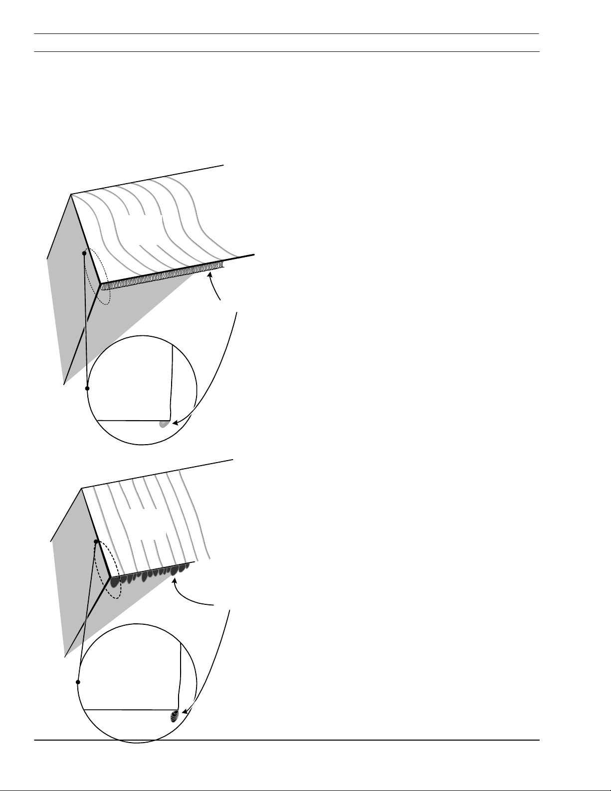
4.2.5 Dross
Lag
Lines
Cut Face
Rollover
Dross is a by-product of the cutting process.
It is the undesirable material that remains
attached to the part. In most cases, dross
can be reduced or eliminated with proper
torch and cutting parameter setup. Refer to
Process Data.
High Speed Dross
Material weld or rollover on bottom surface along kerf.
Difficult to remove. May require grinding or chipping.
“S” shaped lag lines.
· Standoff high (arc voltage)
· Cutting speed fast
Side View
Lag
Lines
Cut Face
Globules
Slow Speed Dross
Forms as globules on bottom along kerf. Removes
easily.
· Cutting speed slow
Side View
PT-24 Precision Plasma System IEFC-S 4-6
Page 57

SECTION 4 OPERATION
Side View
Splatter
Top Dross
Appears as splatter on top of material. Usually
removes easily.
· Cutting speed fast
Cut Face
Intermittent Dross
Appears on top or bottom along kerf.
Non-continuous. Can appear as any kind of dross
· Possible worn consumables
· Standoff high (arc voltage).
Other Factors Affecting Dross;
· Material temperature
· Heavy mill scale or rust
· High carbon alloys
· Contanminated gas source
PT-24 Precision Plasma System IEFC-S 4-7
Page 58

SECTION 4 OPERATION
4.2.6 Dimensional Accuracy
NOTICE
NOTICE
Generally using the slowest possible speed
(within approved levels) will optimize part
accuracy. Select consumables to allow a lower
arc voltage and slower cutting speed.
Recommended cutting speed and arc voltage will
give optimal cutting performance in most cases.
Small incremental adjustments may be
needed due to material quality. material
temperature and specific alloy. The operator
should remember that all cutting variables
are interdependent. Changing one setting
affects all others and cut quality could
deteriorate. Always start at the
recommended settings.
Before attempting ANY corrections, check
cutting variables with the factory
recommended settings/consumable part
numbers listed in the Process Data.
PT-24 Precision Plasma System IEFC-S 4-8
Page 59

SECTION 4 OPERATION
4.3 Influence of Gas Options on Cut Quality
4.3.1 Introduction
All gases are not suitable for all situations. Certain
gases assist in cutting specific materials and
thickness. The following explains why certain gases
are selected and their influence on the finished part.
Other influences such as arc voltage and gas
flow/pressure are covered in the Process Data.
NOTICE
Refer to Cutting Process Data in this section
for recommended flow/pressure settings.
4.3.2 Aluminum
Thickness:
Cut Qualities:
Plasma Gas:
Shield Gas:
Discussion:
Material
All thickness’ between 0.062" to .625" (1,6 mm to 15,9 mm)
· Smooth cut face
· Virtually no dross
Nitrogen
Nitrogen/Methane
Shield mixture is very important. Between 2 and 3 parts nitrogen, to 1 part
methane ratio is desired. Incorrect ratio results in heavy dross.
PT-24 Precision Plasma System IEFC-S 4-9
Page 60

SECTION 4 OPERATION
Refer to Cutting Process Data in the PT24
NOTICE
Manual for recommended flow/pressure
settings.
4.3.3 Carbon Steel
Material
Thickness:
Cut Qualities:
Plasma Gas:
Shield Gas:
Discussion:
Material
Thickness:
Cut Qualities:
26 GA (.018") to 10 GA (.135") (0,5 mm to 3,4 mm)
· Smooth cut face
· Virtually no dross
Oxygen
Oxygen/Nitrogen
Shield gas is normally nitrogen. A small amount of oxygen combined with
nitrogen can effectively improve dross formation on thin material of 26 GA to 10
GA carbon steel. Also. an oxygen only shield may provide acceptable results on
thinner materials.
.125" to .75" (3,2 mm to 19,1 mm)
· Smooth cut face
· Virtually no dross
Plasma Gas:
Shield Gas:
Discussion:
Oxygen
Nitrogen
Cutting carbon steel with oxygen results in an exothermic reaction. This
chemical reaction causes the carbon in the material to burn similar to when oxyfuel cutting. This plus the electrical energy uses lower amperage levels without
sacrificing cut speed.
PT-24 Precision Plasma System IEFC-S 4-10
Page 61

SECTION 4 OPERATION
Refer to Cutting Process Data in the PT24
NOTICE
Manual for recommended flow/pressure
settings.
4.3.4 Stainless Steel
Material
Thickness:
Cut Qualities:
Plasma Gas:
Shield Gas:
Discussion:
Material
Thickness:
Cut Qualities:
22 GA (.028") to 16 GA (0.062") (0,7 mm to 1,6 mm)
· Positive cut angle
· Excellent dross performance
· Shiny cut surface.
Nitrogen
Nitrogen/Methane
Because of high cut speeds. a positive cut face angle is expected. Use a 70amp nozzle at 50 amps to allow more gas to exit the nozzle.
26 GA (.018") to 16 GA (0.062") (0,5 mm to 1,6 mm)
· Dark cut face
· Virtually dross free
· Improved cut squareness
Plasma Gas:
Shield Gas:
Discussion:
Material
Thickness:
Cut Qualities:
Plasma Gas:
Shield Gas:
Discussion:
Oxygen
Oxygen/Nitrogen
Low amperage cutting/slower speeds produce squarer cuts in thin materials.
The oxygen allows for a lower arc voltage, improving cut squareness. The “B”
nozzle is used at 30 amps
.125" to .625" (3,2 mm to 15,9 mm)
· Cut edge dark
· good dross performance
· Good cut angle
Air
Air
When they are the same, the shield and plasma gases combine. This
combination has the effect of increasing the cut gas flow/pressure. This
increased flow/pressure directly influences cut squareness.
PT-24 Precision Plasma System IEFC-S 4-11
Page 62

SECTION 4 OPERATION
NOTICE
Stainless Steel
Refer to Cutting Process Data for
recommended flow/pressure settings.
Material
Thickness:
Cut Qualities:
Plasma Gas:
Shield Gas:
Discussion:
Material
Thickness:
Cut Qualities:
Plasma Gas:
Shield Gas:
.125" to .625" (3,2 mm to 15,9 mm)
· Matted cut edge appearance
· Light gray color
· Much smoother finish
· Possible slight increase in cut angle
Air
Air/Methane
Too much methane in the shield gas mixture can result in more dross formation.
4:1 ratio air to methane is recommended. Because methane is a fuel gas,
possible slight increase in cut angles could be experienced.
.125" to .625" (3,2 mm to 15,9 mm)
· Dark cut face similar to air
· Excellent dross performance
· Good cut angle
Nitrogen
Nitrogen
Discussion:
Material
Thickness:
Cut Qualities:
Plasma Gas:
Shield Gas:
Discussion:
Shield and plasma gases combine, the volume/pressure of shield gas can
negatively affect cut squareness. Higher shield volume produces a negative cut
angle. A lower volume, produces a positive angle.
.187" to .625" (4,7 mm to 15,9 mm)
· Shiny cut face
· Lip formation at the bottom
· Dross formation can be extensive and difficult to remove
Nitrogen
Nitrogen/Methane
Because methane is a fuel gas, flow/pressure rates can affect the cut angle.
High flow/pressure results in a negative cut angle, low flow/pressure results in a
positive cut angle. Nitrogen to methane ratio is 10 to 14 parts N2/ 1 part CH4.
The lip formed on the cut face bottom is severe, making Nitrogen/Methane
shield gas combination unsuitable for some finished part applications.
PT-24 Precision Plasma System IEFC-S 4-12
Page 63

SECTION 4 OPERATION
4.4 Process Data
4.4.1 Introduction
The following information is a result of many hours of
testing and is a general guide for setting up and
cutting with a PT-24 Precision Plasmarc® System.
In most cases these settings will provide a quality
cut. The data contains values for:
· cutting aluminum, carbon and stainless steel
· arc voltage (standoff)
· cutting speed
· current (amperes)
· gas flow rates for all plasma/shield gas
combinations
This same data is contained in SDP files. (See your
control manual for more information on SDP files.)
Also included is information on consumable part
numbers for current being used.
PT-24 Precision Plasma System IEFC-S 4-13
Page 64

SECTION 4 OPERATION
4.4.2 IFC PT-24 Process Data
Initial Amperes: 15
Final Amperes: 30
®
Shield Mix Gas:
Material: Aluminum
Plasm a Gas:
Shield Gas:
PT-24 Torch with Integrated Flow Control
Nitrogen, N2 @ 150 PSI /10.4 Bar
Nitrogen, N2 @ 150 PSI /10.4 Bar
Methane, CH4 @ 100 PSI / 6,9 Bar
Torch Body
P/N 21758
Water Baffle
P/N 21725
O-Ring
P/N 638797
O-Ring
P/N 86W62
O-Ring
P/N 950714
O-Ring
P/N 98W18
Electrode
P/N 21539
! Swirl Baffle
P/N 21536 (3 holes)
! Nozzle
P/N 21541, "B"
Nozzle Retainer/Diffuser
P/N 22007
Shield Cup Insulator
P/N 22010
Insulator Shield Retainer
w/O-Ring P/N 21712
O-Ring - Shield Retainer ,
(Ref. P/N 996528)
Cup shield w/Retainer
P/N 22531
! Baffle and Nozzle are the
only two replaceable torch
front-end parts that may
vary with amperage
PT-24 Precision Plasma System IEFC-S 4-14
Page 65

SECTION 4 OPERATION
Process Data
Precision Plasma Integrated Flow Control
Plasma Gas Shield Gas 1 Shield Gas 2
Material Thickness
In.
0,062 0,075 0,09 0,125 0,187 0,250
mm
Timers
Pierce Delay (sec.)
Initial to Final Current (sec.) 0,2 0,2 0,2 0,2 0,2 0,2
Setup Parameters
Plasma Start Gas 1- psi/bar
Plasma Cut Gas 1- psi/bar
Shield Gas
1-Start - psi/bar
1- Cut - psi/bar
2- Cut - psi/bar
132,0
N2 N2 CH4
1,6 1,9 2,3 3,2 4,7 6,4
0 0 0 0 0 0
93,1
/6,3
/9,0
42,9
/2,9
16,5
/1,3
12,3
/0,8
93,1
/6,3
132,0
/9,0
42,9
/2,9
16,5
/1,3
12,3
/0,8
15 Initial / 30 Final Amperes
Aluminum
93,1
/6,3
132,0
/9,0
42,9
/2,9
16,5
/1,3
12,3
/0,8
93,1
/6,3
132,0
/9,0
42,9
/2,9
16,5
/1,3
12,3
/0,8
93,1
/6,3
132,0
/9,0
42,9
/2,9
16,5
/1,3
12,3
/0,8
93,1
/6,3
132,0
/9,0
42,9
/2,9
16,5
/1,3
12,3
/0,8
Arc Voltage (standoff) 150 152 153 165 180 189
Initial Height
Pierce Height
Cutting Height
In. 0,100 0,100 0,100 0,100 0,100 0,100
mm 2,54 2,54 2,54 2,54 2,54 2,54
In. 0,150 0,150 0,150 0,160 0,220 0,250
mm 6,35 6,35 6,35 4,04 5,59 6,35
In. 0,125 0,130 0,135 0,165 0,220 0,250
mm 3,18 3,30 3,43 4,19 5,59 6,35
Travel Speed
IPM 150 135 105 78 45 40
MM/MIN
Notes:
Pilot Arc –LOW,
PT-24 Precision Plasma System IEFC-S 4-15
3810 3429 2667 1981 1143 1016
Page 66

SECTION 4 OPERATION
Material: Aluminum
Initial Amperes: 28
Final Amperes: 55
Plasm a Gas:
Shield Gas:
®
Shield Mix Gas:
PT-24 Torch with Integrated Flow Control
Nitrogen, N2 @ 150 PSI /10.4 Bar
Nitrogen, N2 @ 150 PSI /10.4 Bar
Methane, CH4 @ 100 PSI / 6,9 Bar
Torch Body
P/N 21758
Water Baffle
P/N 21725
O-Ring
P/N 638797
O-Ring
P/N 86W62
O-Ring
P/N 950714
O-Ring
P/N 98W18
Electrode
P/N 21539
! Swirl Baffle
P/N 21692 (4 holes)
! Nozzle
P/N 21542, "C"
Nozzle Retainer/Diffuser
P/N 22007
Shield Cup Insulator
P/N 22010
Insulator Shield Retainer
w/O-Ring P/N 21712
O-Ring - Shield Retainer ,
(Ref. P/N 996528)
Cup shield w/Retainer
P/N 22531
! Baffle and Nozzle are the
only two replaceable torch
front-end parts that may
vary with amperage
PT-24 Precision Plasma System IEFC-S 4-16
Page 67

SECTION 4 OPERATION
Process Data
Precision Plasma Integrated Flow Control
Plasma Gas Shield Gas 1 Shield Gas 2
Material Thickness
In.
0,062 0,125 0,125 0,250
mm
Timers
Pierce Delay (sec.)
Initial to Final Current (sec.) 0,2 0,2 0,2 0,2
Setup Parameters
Plasma Start Gas 1- psi/bar
Plasma Cut Gas 1- psi/bar
Shield Gas
1-Start - psi/bar
1- Cut - psi/bar
2- Cut - psi/bar
100,3
N2 N2 CH4
1,6 3,2 4,7 6,4
0 0 0 0
64
/4,4
/6,8
42,9
/2,9
16
/1,1
12,3
/0,8
64
/4,4
100,3
/6,8
42,9
/2,9
16
/1,1
12,3
/0,8
28 Initial – 55 Final Amperes
Aluminum
64
/4,4
100,3
/6,8
42,9
/2,9
16
/1,1
12,3
/0,8
64
/4,4
112,3
/7,6
42,9
/2,9
16
/1,1
12,3
/0,8
Arc Voltage (standoff) 136 139 152 168
Initial Height
Pierce Height
Cutting Height
In. 0,100 0,100 0,100 0,100
mm 2,54 2,54 2,54 2,54
In. 0,09 0,09 0,180 0,150
mm 2,29 2,29 4,57 3,81
In. 0,09 0,09 0,180 0,225
mm
2,29 2,29 4,57 5,72
Travel Speed
IPM 170 130 78 46
MM/MIN
4318 3302 1981 1168
Notes:
Pilot Arc –HIGH,
PT-24 Precision Plasma System IEFC-S 4-17
Page 68

SECTION 4 OPERATION
)
Material: Aluminum
Initial Amperes: 35
Final Amperes: 70
Plasm a Gas:
Shield Gas:
®
Shield Mix Gas:
PT-24 Torch with Integrated Flow Control
Nitrogen, N2 @ 150 PSI /10.4 Bar
Nitrogen, N2 @ 150 PSI /10.4 Bar
Methane, CH4 @ 100 PSI / 6,9 Bar
Torch Body
P/N 21758
Water Baffle
P/N 21725
O-Ring
P/N 638797
O-Ring
P/N 86W62
O-Ring
P/N 950714
O-Ring
P/N 98W18
Electrode
P/N 21539
! Swirl Baffle
P/N 21692 (4 holes
! Nozzle
P/N 21543, "D"
Nozzle Retainer/Diffuser
P/N 22007
Shield Cup Insulator
P/N 22010
Insulator Shield Retainer
w/O-Ring P/N 21712
O-Ring - Shield Retainer
(Ref. P/N 996528)
Cup shield w/Retainer
P/N 22531
! Baffle and Nozzle are the
only two replaceable torch
front-end parts that may
vary with amperage
PT-24 Precision Plasma System IEFC-S 4-18
Page 69

SECTION 4 OPERATION
Process Data
Precision Plasma Integrated Flow Control
Plasma Gas Shield Gas 1 Shield Gas 2
Material Thickness
In.
0,187 0,250 0,375 0,500
mm
Timers
Pierce Delay (sec.)
Initial to Final Current (sec.) 0,2 0,2 0,2 0,2
Setup Parameters
Plasma Start Gas 1- psi/bar
Plasma Cut Gas 1- psi/bar
Shield Gas
1-Start - psi/bar
1- Cut - psi/bar
2- Cut - psi/bar
N2 N2 CH4
4,7 6,4 9,5 12,7
0 0 0,1 0,2
76,6
/5,2
68,6
/4,7
43,8
/3,0
15,4
/1,0
11,7
/0,8
76,6
/5,2
108,5
/7
43,8
/3,0
15,4
/1,0
11,7
/0,8
35 Initial / 70 Final Amperes
Aluminum
76,6
/5,2
108,5
/7
43,8
/3,0
15,4
/1,0
11,7
/0,8
76,6
/5,2
108,5
/7
43,8
/3,0
15,4
/1,0
11,7
/0,8
Arc Voltage (standoff) 150 157 168 182
Initial Height
Pierce Height
Cutting Height
In. 0,100 0,100 0,100 0,100
mm 2,54 2,54 2,54 2,54
In. 0,190 0,150 0,240 0,260
mm 4,83 3,81 6,10 6,60
In. 0,190 0,225 0,240 0,260
mm 4,83 5,72 6,10 6,60
Travel Speed
IPM 80 65 66 30
MM/MIN
3032 1651 1397 762
Notes:
Pilot Arc –HIGH,
PT-24 Precision Plasma System IEFC-S 4-19
Page 70

SECTION 4 OPERATION
Material: Aluminum
Initial Amperes: 50
Final Amperes: 100
Plasm a Gas:
Shield Gas:
®
Shield Mix Gas:
PT-24 Torch with Integrated Flow Control
Nitrogen, N2 @ 150 PSI /10.4 Bar
Nitrogen, N2 @ 150 PSI /10.4 Bar
Methane, CH4 @ 100 PSI / 6,9 Bar
Torch Body
P/N 21758
Water Baffle
P/N 21725
O-Ring
P/N 638797
O-Ring
P/N 86W62
O-Ring
P/N 950714
O-Ring
P/N 98W18
Electrode
P/N 21539
! Swirl Baffle
P/N 21692 (4 holes)
! Nozzle
P/N 21923, "E"
Nozzle Retainer/Diffuser
P/N 22007
Shield Cup Insulator
P/N 22010
Insulator Shield Retainer
w/O-Ring P/N 21712
O-Ring - Shield Retainer ,
(Ref. P/N 996528)
Cup shield w/Retainer
P/N 22531
! Baffle and Nozzle are the
only two replaceable torch
front-end parts that may
vary with amperage
PT-24 Precision Plasma System IEFC-S 4-20
Page 71

SECTION 4 OPERATION
Process Data
Precision Plasma Integrated Flow Control
Plasma Gas Shield Gas 1 Shield Gas 2
Material Thickness
In.
0,250 0,375 0,500 0,625
mm
Timers
Pierce Delay (sec.)
Initial to Final Current (sec.) 0,2 0,2 0,2 0,2
Setup Parameters
Plasma Start Gas 1- psi/bar
Plasma Cut Gas 1- psi/bar
Shield Gas
1-Start - psi/bar
1- Cut - psi/bar
2- Cut - psi/bar
N2 N2 CH4
6,4 9,5 12,7 15,9
0 0 0,1 0,1
76,4
/5,2
95,6
/6,5
61,5
/4,2
27,3
/1,9
17,9
/1,2
76,4
/5,2
95,6
/6,5
61,5
/4,2
27,3
/1,9
17,9
/1,2
50 Initial / 100 Final Amperes
Aluminum
76,4
/5,2
95,6
/6,5
61,5
/4,2
27,3
/1,9
17,9
/1,2
76,4
/5,2
95,6
/6,5
61,5
/4,2
27,3
/1,9
17,9
/1,2
Arc Voltage (standoff) 155 160 166 174
Initial Height
Pierce Height
Cutting Height
In. 0,100 0,100 0,100 0,100
mm 2,54 2,54 2,54 2,54
In. 0,190 0,225 0,260 0,285
mm 4,83 5,72 6,60 7,24
In. 0,190 0,225 0,260 0,285
mm 4,83 5,72 6,60 7,24
Travel Speed
IPM 95 80 65 50
MM/MIN
2413 2032 1778 1270
Notes:
Pilot Arc –HIGH,
PT-24 Precision Plasma System IEFC-S 4-21
Page 72

SECTION 4 OPERATION
Material: Carbon Steel
Initial Amperes: 16
Final Amperes: 16
Plasm a Gas:
Shield Gas:
®
Shield Mix Gas:
PT-24 Torch with Integrated Flow Control
Oxygen, O2 @ 150 PSI / 10.4 Bar
Nitrogen, N2 @ 150 PSI /10.4 Bar
Oxygen, O2 @ 150 PSI / 10.4 Bar
Torch Body
P/N 21758
Water Baffle
P/N 21725
O-Ring
P/N 638797
O-Ring
P/N 86W62
O-Ring
P/N 950714
O-Ring
P/N 98W18
Electrode
P/N 21539
! Swirl Baffle
P/N 21852 (2 holes)
! Nozzle
P/N 21540, "A"
Nozzle Retainer/Diffuser
P/N 22007
Shield Cup Insulator
P/N 22010
Insulator Shield Retainer
w/O-Ring P/N 21712
O-Ring - Shield Retainer ,
(Ref. P/N 996528)
Cup shield w/Retainer
P/N 22531
! Baffle and Nozzle are the
only two replaceable torch
front-end parts that may
vary with amperage
PT-24 Precision Plasma System IEFC-S 4-22
Page 73

SECTION 4 OPERATION
Process Data
Precision Plasma Integrated Flow Control
Plasma Gas Shield Gas 1 Shield Gas 2
16 Initial / 16 Final Amperes
Carbon Steel
O2 N2 O2
Material Thickness
In.
mm
Timers
Pierce Delay (sec.)
Initial to Final Current (sec.)
Setup Parameters
Plasma Start Gas 1- psi/bar
Plasma Cut Gas 1- psi/bar
Shield Gas
1-Start - psi/bar
1- Cut - psi/bar
2- Cut - psi/bar
20Ga 18Ga 16Ga 14Ga 12Ga 10Ga
0,9 1,2 1,6 2,0 2,7 3,4
0 0 0 0,1 0,5 0,5
0,2 0,2 0,2 0,2 0,2 0,2
71,3
/4,9
83,2
/5,7
12.9
/0.89
4.1
/0.28
2.2
/0.15
71,3
/4,9
83,2
/5,7
12.9
/0.89
4.1
/0.28
2.2
/0.15
71,3
/4,9
83,2
/5,7
12.9
/0.89
4.1
/0.28
2.4
/0.27
71,3
/4,9
83,2
/5,7
12.9
/0.89
4.1
/0.28
3.0
/0.21
71,3
/4,9
83,2
/5,7
12.9
/0.89
3.1
/0.21
2.2
/0.15
71,3
/4,9
83,2
/5,7
12.9
/0.89
3.5
/0.24
2.3
/0.16
Arc Voltage (standoff) 108 110 120 123 121 123
Initial Height
Pierce Height
Cutting Height
In.
mm
In.
mm
In.
mm
0,04 0,04 0,04 0,04 0,04 0,04
1,02 1,02 1,02 1,02 1,02 1,02
0,06 0,06 0,06 0,06 0,115 0,115
1,52 1,52 1,52 1,52 2,92 2,92
0,108 0,118 0,140 0,144 0,126 0,126
2,74 2,74 3,56 3,66 3,20 3,20
Travel Speed
IPM
MM/MIN
Notes:
Pilot Arc –LOW,
PT-24 Precision Plasma System IEFC-S
95 80 75 55 50 33
2413 2032 1905 1397 1270 838
4-23
Page 74

SECTION 4 OPERATION
Material: Carbon Steel
Initial Amperes: 18
Final Amperes: 35
Plasm a Gas:
Shield Gas:
®
Shield Mix Gas:
PT-24 Torch with Integrated Flow Control
Oxygen, O2 @ 150 PSI / 10.4 Bar
Nitrogen, N2 @ 150 PSI /10.4 Bar
Oxygen, O2 @ 150 PSI / 10.4 Bar
Torch Body
P/N 21758
Water Baffle
P/N 21725
O-Ring
P/N 638797
O-Ring
P/N 86W62
O-Ring
P/N 950714
O-Ring
P/N 98W18
Electrode
P/N 21539
! Swirl Baffle
P/N 21536 (3 holes)
! Nozzle
P/N 21541, "B"
Nozzle Retainer/Diffuser
P/N 22007
Shield Cup Insulator
P/N 22010
Insulator Shield Retainer
w/O-Ring P/N 21712
O-Ring - Shield Retainer ,
(Ref. P/N 996528)
Cup shield w/Retainer
P/N 22531
! Baffle and Nozzle are the
only two replaceable torch
front-end parts that may
vary with amperage
PT-24 Precision Plasma System IEFC-S 4-24
Page 75

SECTION 4 OPERATION
Process Data
Precision Plasma Integrated Flow Control
Plasma Gas Shield Gas 1 Shield Gas 2
Material Thickness
In.
14Ga 0,125 0,135 0,187 0,250
mm
Timers
Pierce Delay (sec.)
Initial to Final Current (sec.) 0,2 0,2 0,2 0,2 0,2
Setup Parameters
Plasma Start Gas 1- psi/bar
Plasma Cut Gas 1- psi/bar
Shield Gas
1-Start - psi/bar
1- Cut - psi/bar
2- Cut - psi/bar
102,9
O2 N2 O2
1,9 3,2 3,4 4,7 6,4
0 0 0 0 0,2
86,9
/5,9
/7,0
46,5
/3,2
0 0 0 0 0
2,5
/0,2
86,9
/5,9
102,9
/7,0
46,5
/3,2
2,5
/0,2
18 Initial / 35 Final Amperes
Carbon Steel
86,9
/5,9
102,9
/7,0
46,5
/3,2
2,5
/0,2
86,9
/5,9
102,9
/7,0
46,5
/3,2
2,5
/0,2
86,9
/5,9
102,9
/7,0
46,5
/3,2
2,5
/0,2
Arc Voltage (standoff) 113 119 120 122 124
Initial Height
Pierce Height
Cutting Height
In. 0,04 0,04 0,04 0,04 0,04
mm 1,02 1,02 1,02 1,02 1,02
In. 0,103 0,113 0,118 0,118 0,130
mm 2,62 2,87 3,00 3,00 3,30
In. 0,103 0,113 0,118 0,118 0,130
mm 2,62 2,87 3,00 3,00 3,30
Travel Speed
IPM 80 55 52 40 30
MM/MIN
3032 1397 1320 1016 762
Notes:
Pilot Arc –LOW,
PT-24 Precision Plasma System IEFC-S 4-25
Page 76

SECTION 4 OPERATION
Material: Carbon Steel
Initial Amperes: 23
Final Amperes: 45
Plasm a Gas:
Shield Gas:
®
Shield Mix Gas:
PT-24 Torch with Integrated Flow Control
Oxygen, O2 @ 150 PSI / 10.4 Bar
Nitrogen, N2 @ 150 PSI /10.4 Bar
Oxygen, O2 @ 150 PSI / 10.4 Bar
Torch Body
P/N 21758
Water Baffle
P/N 21725
O-Ring
P/N 638797
O-Ring
P/N 86W62
O-Ring
P/N 950714
O-Ring
P/N 98W18
Electrode
P/N 21539
! Swirl Baffle
P/N 21692 (4 holes)
! Nozzle
P/N 21542, "C"
Nozzle Retainer/Diffuser
P/N 22007
Shield Cup Insulator
P/N 22010
Insulator Shield Retainer
w/O-Ring P/N 21712
O-Ring - Shield Retainer ,
(Ref. P/N 996528)
Cup shield w/Retainer
P/N 22531
! Baffle and Nozzle are the
only two replaceable torch
front-end parts that may
vary with amperage
PT-24 Precision Plasma System IEFC-S 4-26
Page 77

SECTION 4 OPERATION
Process Data
Precision Plasma Integrated Flow Control
Plasma Gas Shield Gas 1 Shield Gas 2
Material Thickness
Timers
Initial to Final Current (sec.) 0,2 0,2 0,2 0,2 0,2
Setup Parameters
Plasma Start Gas 1- psi/bar
Plasma Cut Gas 1- psi/bar
Shield Gas
In.
mm
Pierce Delay (sec.)
1-Start - psi/bar
1- Cut - psi/bar
2- Cut - psi/bar
0,125 0,135 0,187 0,250 0,375
O2 N2 O2
3,2 3,4 4,7 6,4 9,5
0 0,3 0,3 0,3 0,4
73,8
/5,0
86,2
/5,9
48,1
/3,3
11,2
/0,8
0 0 0 0 0
73,8
/5,0
86,2
/5,9
48,1
/3,3
11,2
/0,8
23 Initial / 45 Final Amperes
Carbon Steel
73,8
/5,0
86,2
/5,9
48,1
/3,3
11,2
/0,8
73,8
/5,0
86,2
/5,9
48,1
/3,3
11,2
/0,8
73,8
/5,0
86,2
/5,9
48,1
/3,3
11,2
/0,8
Arc Voltage (standoff) 108 111 114 121 124
Initial Height
Pierce Height
Cutting Height
In. 0,100 0,100 0,100 0,100 0,100
mm 25,4 25,4 25,4 25,4 25,4
In. 0,145 0,155 0,145 0,205 0,164
mm 3,68 3,94 3,68 5,21 2,41
In. 0,145 0,155 0,145 0,205 0,164
mm 3,68 3,94 3,68 5,21 2,41
Travel Speed
IPM 60 50 45 35 20
MM/MIN
1524 1270 1143 889 508
Notes:
Pilot Arc –HIGH,
PT-24 Precision Plasma System IEFC-S 4-27
Page 78

SECTION 4 OPERATION
Material: Carbon Steel
Initial Amperes: 35
Final Amperes: 70
Plasm a Gas:
Shield Gas:
®
Shield Mix Gas:
PT-24 Torch with Integrated Flow Control
Oxygen, O2 @ 150 PSI / 10.4 Bar
Nitrogen, N2 @ 150 PSI /10.4 Bar
Oxygen, O2 @ 150 PSI / 10.4 Bar
Torch Body
P/N 21758
Water Baffle
P/N 21725
O-Ring
P/N 638797
O-Ring
P/N 86W62
O-Ring
P/N 950714
O-Ring
P/N 98W18
Electrode
P/N 21539
! Swirl Baffle
P/N 21692 (4 holes)
! Nozzle
P/N 21543, "D"
Nozzle Retainer/Diffuser
P/N 22007
Shield Cup Insulator
P/N 22010
Insulator Shield Retainer
w/O-Ring P/N 21712
O-Ring - Shield Retainer ,
(Ref. P/N 996528)
Cup shield w/Retainer
P/N 22531
! Baffle and Nozzle are the
only two replaceable torch
front-end parts that may
vary with amperage
PT-24 Precision Plasma System IEFC-S 4-28
Page 79

SECTION 4 OPERATION
Process Data
Precision Plasma Integrated Flow Control
Plasma Gas Shield Gas 1 Shield Gas 2
Material Thickness
Timers
Initial to Final Current (sec.) 0,2 0,2 0,2 0,2 0,2 0,2
Setup Parameters
Plasma Start Gas 1- psi/bar
Plasma Cut Gas 1- psi/bar
Shield Gas
In.
mm
Pierce Delay (sec.)
1-Start - psi/bar
1- Cut - psi/bar
2- Cut - psi/bar
0,187 0,250 0,312 0,375 0,500 0,625
O2 N2 O2
4,7 6,4 7,9 9,5 12,7 15,9
0,3 0,3 0,3 0,4 0,5 0,5
66,7
/4,5
81,6
/5,6
49,1
/3,3
20,6
/1,4
0 0 0 0 0 0
66,7
/4,5
81,6
/5,6
49,1
/3,3
28,4
/1,9
35 Initial / 70 Final Amperes
Carbon Steel
66,7
/4,5
81,6
/5,6
49,1
/3,3
20,6
/1,4
66,7
/4,5
81,6
/5,6
49,1
/3,3
28,4
/1,9
66,7
/4,5
81,6
/5,6
49,1
/3,3
13,5
/0,9
66,7
/4,5
81,6
/5,6
49,1
/3,3
135,
/0,9
Arc Voltage (standoff) 108 110 114 113 135 140
Initial Height
Pierce Height
Cutting Height
In. 0,100 0,100 0,100 0,100 0,100 0,100
mm 2,54 2,54 2,54 2,54 2,54 2,54
In. 0,140 0,140 0,165 0,160 0,275 0,315
mm 3,56 3,56 4,19 40,06 6,99 8,00
In. 0,140 0,140 0,165 0,160 0,275 0,315
mm 3,56 3,56 4,19 40,06 6,99 8,00
Travel Speed
IPM 110 95 70 60 30 25
MM/MIN
Notes:
Pilot Arc –HIGH,
PT-24 Precision Plasma System IEFC-S 4-29
2794 2413 1778 1524 762 635
Page 80

SECTION 4 OPERATION
Material: Carbon Steel
Initial Amperes: 50
Final Amperes: 100
Plasm a Gas:
Shield Gas:
®
Shield Mix Gas:
PT-24 Torch with Integrated Flow Control
Oxygen, O2 @ 150 PSI / 10.4 Bar
Nitrogen, N2 @ 150 PSI /10.4 Bar
Oxygen, O2 @ 150 PSI / 10.4 Bar
Torch Body
P/N 21758
Water Baffle
P/N 21725
O-Ring
P/N 638797
O-Ring
P/N 86W62
O-Ring
P/N 950714
O-Ring
P/N 98W18
Electrode
P/N 21539
! Swirl Baffle
P/N 21692 (4 holes)
! Nozzle
P/N 21923, "E"
Nozzle Retainer/Diffuser
P/N 22007
Shield Cup Insulator
P/N 22010
Insulator Shield Retainer
w/O-Ring P/N 21712
O-Ring - Shield Retainer ,
(Ref. P/N 996528)
Cup shield w/Retainer
P/N 22531
! Baffle and Nozzle are the
only two replaceable torch
front-end parts that may
vary with amperage
PT-24 Precision Plasma System IEFC-S 4-30
Page 81

SECTION 4 OPERATION
Process Data
Precision Plasma Integrated Flow Control
Plasma Gas Shield Gas 1 Shield Gas 2
Material Thickness
Timers
Initial to Final Current (sec.) 0,2 0,2 0,2 0,2 0,2
Setup Parameters
Plasma Start Gas 1- psi/bar
Plasma Cut Gas 1- psi/bar
Shield Gas
In.
mm
Pierce Delay (sec.)
1-Start - psi/bar
1- Cut - psi/bar
2- Cut - psi/bar
0,312 0,375 0,500 0,625 0,750
O2 N2 N2
7,9 9,5 12,9 15,9 19,1
0,3 0,3 0,4 0,5 0,5
77,5
/5,2
89,5
/6,1
60,5
/4,1
26,3
/1,8
0 0 0 0 0
77,5
/5,2
89,5
/6,1
60,5
/4,1
26,3
/1,8
50 Initial / 100 Final Amperes
Carbon Steel
77,5
/5,2
89,5
/6,1
60,5
/4,1
26,3
/1,8
77,5
/5,2
89,5
/6,1
60,5
/4,1
26,3
/1,8
77,5
/5,2
89,5
/6,1
60,5
/4,1
26,3
/1,8
Arc Voltage (standoff) 115 120 132 137 142
Initial Height
Pierce Height
Cutting Height
In. 0,100 0,100 0,100 0,100 0,100
mm 2,54 2,54 2,54 2,54 2,54
In. 0,175 0,190 0,280 0,290 0,320
mm 4,45 4,83 7,11 7,37 8,13
In. 0,175 0,190 0,280 0,290 0,320
mm 4,45 4,83 7,11 7,37 8,13
Travel Speed
IPM 90 80 50 30 25
MM/MIN
2290 2030 1270 760 630
Notes:
Pilot Arc –HIGH,
PT-24 Precision Plasma System IEFC-S 4-31
Page 82

SECTION 4 OPERATION
Material: Stainless Steel
Initial Amperes: 15
Final Amperes: 30
Plasm a Gas:
Shield Gas:
®
Shield Mix Gas:
PT-24 Torch with Integrated Flow Control
Oxygen, O2 @ 150 PSI / 10.4 Bar
Nitrogen, N2 @ 150 PSI /10.4 Bar
Oxygen, O2 @ 150 PSI / 10.4 Bar
Torch Body
P/N 21758
Water Baffle
P/N 21725
O-Ring
P/N 638797
O-Ring
P/N 86W62
O-Ring
P/N 950714
O-Ring
P/N 98W18
Electrode
P/N 21539
! Swirl Baffle
P/N 21536 (3 holes)
! Nozzle
P/N 21541, "B"
Nozzle Retainer/Diffuser
P/N 22007
Shield Cup Insulator
P/N 22010
Insulator Shield Retainer
w/O-Ring P/N 21712
O-Ring - Shield Retainer ,
(Ref. P/N 996528)
Cup shield w/Retainer
P/N 22531
! Baffle and Nozzle are the
only two replaceable torch
front-end parts that may
vary with amperage
PT-24 Precision Plasma System IEFC-S 4-32
Page 83

SECTION 4 OPERATION
Process Data
Precision Plasma Integrated Flow Control
Plasma Gas Shield Gas 1 Shield Gas 2
Material Thickness
In.
26Ga 24Ga 22Ga 18Ga 16Ga
mm
Timers
Pierce Delay (sec.)
Initial to Final Current (sec.) 0,2 0,2 0,2 0,2 0,2
Setup Parameters
Plasma Start Gas 1- psi/bar
Plasma Cut Gas 1- psi/bar
Shield Gas
1-Start - psi/bar
1- Cut - psi/bar
2- Cut - psi/bar
116,8
O2 N2 O2
0,4 0,6 0,7 1,2 1,6
0 0 0 0 0
99,8
/6,8
/7,9
32,7
/2,2
10,3
/0,7
7,1
/0,5
99,8
/6,8
116,8
/7,9
32,7
/2,2
10,3
/0,7
7,1
/0,5
15 Initial / 30 Final Amperes
Stainless Steel
99,8
/6,8
116,8
/7,9
32,7
/2,2
10,3
/0,7
7,1
/0,5
99,8
/6,8
116,8
/7,9
32,7
/2,2
10,3
/0,7
7,1
/0,5
99,8
/6,8
116,8
/7,9
32,7
/2,2
10,3
/0,7
7,1
/0,5
Arc Voltage (standoff) 105 105 107 109 111
Initial Height
Pierce Height
Cutting Height
In. 0,06 0,06 0,06 0,06 0,06
mm 1,52 1,52 1,52 1,52 1,52
In. 0,105 0,120 0,107 0,109 0,111
mm 2,67 3,05 2,72 2,77 2,82
In. 0,105 0,120 0,107 0,109 0,111
mm 2,67 3,05 2,72 2,77 2,82
Travel Speed
IPM 250 200 190 140 100
MM/MIN
6350 5080 4826 3556 2540
Notes:
Pilot Arc –LOW,
PT-24 Precision Plasma System IEFC-S 4-33
Page 84

SECTION 4 OPERATION
Material: Stainless Steel
Initial Amperes: 25
Final Amperes: 50
Plasm a Gas:
Shield Gas:
®
Shield Mix Gas:
PT-24 Torch with Integrated Flow Control
Air @ 150 PSI / 10.4 Bar
Air @ 150 PSI / 10.4 Bar
Torch Body
P/N 21758
Water Baffle
P/N 21725
O-Ring
P/N 638797
O-Ring
P/N 86W62
O-Ring
P/N 950714
O-Ring
P/N 98W18
Electrode
P/N 21539
! Swirl Baffle
P/N 21692 (4 holes)
! Nozzle
P/N 21542, "C"
Nozzle Retainer/Diffuser
P/N 22007
Shield Cup Insulator
P/N 22010
Insulator Shield Retainer
w/O-Ring P/N 21712
O-Ring - Shield Retainer ,
(Ref. P/N 996528)
Cup shield w/Retainer
P/N 22531
! Baffle and Nozzle are the
only two replaceable torch
front-end parts that may
vary with amperage
PT-24 Precision Plasma System IEFC-S 4-34
Page 85

SECTION 4 OPERATION
Process Data
Precision Plasma Integrated Flow Control
Plasma Gas Shield Gas 1 Shield Gas 2
Material Thickness
Timers
Initial to Final Current (sec.) 0,2 0,2 0,2 0,2
Setup Parameters
Plasma Start Gas 1- psi/bar
Plasma Cut Gas 1- psi/bar
Shield Gas
In.
mm
Pierce Delay (sec.)
1-Start - psi/bar
1- Cut - psi/bar
2- Cut - psi/bar
0,125 0,187 0,250 0,375
125,7
Air Air
3,2 4,7 6,4 9,5
0 0 0,1 0,2
77
/5,2
/8,5
44,5
/3,0
31,9
/2,2
0 0 0 0
77
/5,2
125,7
/8,5
44,5
/3,0
31,9
/2,2
25 Intial / 50 Final Amperes
Stainless Steel
77
/5,2
125,7
/8,5
44,5
/3,0
31,9
/2,2
77
/5,2
125,7
/8,5
44,5
/3,0
31,9
/2,2
Arc Voltage (standoff) 134 140 145 157
Initial Height
Pierce Height
Cutting Height
In. 0,100 0,100 0,100 0,100
mm 2,54 2,54 2,54 2,54
In. 0,145 0,165 0,160 0,220
mm 3,68 4,19 40,06 5,59
In. 0,145 0,165 0,160 0,220
mm 3,68 4,19 40,06 5,59
Travel Speed
IPM 90 60 40 18
MM/MIN
2286 1524 1016 457
Notes:
Pilot Arc –HIGH,
PT-24 Precision Plasma System IEFC-S 4-35
Page 86

SECTION 4 OPERATION
Material: Stainless Steel
Initial Amperes: 35
Final Amperes: 70
Plasm a Gas:
Shield Gas:
®
Shield Mix Gas:
PT-24 Torch with Integrated Flow Control
Air @ 150 PSI / 10.4 Bar
Air @ 150 PSI / 10.4 Bar
Torch Body
P/N 21758
Water Baffle
P/N 21725
O-Ring
P/N 638797
O-Ring
P/N 86W62
O-Ring
P/N 950714
O-Ring
P/N 98W18
Electrode
P/N 21539
! Swirl Baffle
P/N 21692 (4 holes)
! Nozzle
P/N 21543, "D"
Nozzle Retainer/Diffuser
P/N 22007
Shield Cup Insulator
P/N 22010
Insulator Shield Retainer
w/O-Ring P/N 21712
O-Ring - Shield Retainer ,
(Ref. P/N 996528)
Cup shield w/Retainer
P/N 22531
! Baffle and Nozzle are the
only two replaceable torch
front-end parts that may
vary with amperage
PT-24 Precision Plasma System IEFC-S 4-36
Page 87

SECTION 4 OPERATION
Process Data
Precision Plasma Integrated Flow Control
Plasma Gas Shield Gas 1 Shield Gas 2
Material Thickness
Timers
Initial to Final Current (sec.) 0,2 0,2 0,2 0,2
Setup Parameters
Plasma Start Gas 1- psi/bar
Plasma Cut Gas 1- psi/bar
Shield Gas
In.
mm
Pierce Delay (sec.)
1-Start - psi/bar
1- Cut - psi/bar
2- Cut - psi/bar
0,187 0,250 0,375 0,500
105,5
Air Air
4,7 6,4 9,5 12,7
0,3 0,4 0,5 0,6
79,1
/5,4
/7,2
62,6
/4,3
38,3
/2,6
0 0 0 0
79,1
/5,4
105,5
/7,2
62,6
/4,3
38,3
/2,6
35 Initial / 70 Final Amperes
Stainless Steel
79,1
/5,4
105,5
/7,2
62,6
/4,3
38,3
/2,6
79,1
/5,4
105,5
/7,2
62,6
/4,3
38,3
/2,6
Arc Voltage (standoff) 131 152 158 157
Initial Height
Pierce Height
Cutting Height
In. 0,100 0,100 0,100 0,100
mm 2,54 2,54 2,54 2,54
In. 0,150 0,240 0,280 0,280
mm 3,81 6,10 7,11 7,11
In. 0,150 0,240 0,280 0,280
mm 3,81 6,10 7,11 7,11
Travel Speed
IPM 100 50 28 20
MM/MIN
2540 2270 711 609
Notes:
Pilot Arc –HIGH,
PT-24 Precision Plasma System IEFC-S 4-37
Page 88
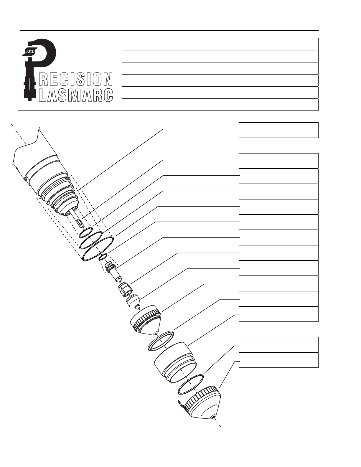
SECTION 4 OPERATION
Material: Stainless Steel
Initial Amperes: 50
Final Amperes: 100
Plasm a Gas:
Shield Gas:
®
Shield Mix Gas:
PT-24 Torch with Integrated Flow Control
Air @ 150 PSI / 10.4 Bar
Air @ 150 PSI / 10.4 Bar
Torch Body
P/N 21758
Water Baffle
P/N 21725
O-Ring
P/N 638797
O-Ring
P/N 86W62
O-Ring
P/N 950714
O-Ring
P/N 98W18
Electrode
P/N 21539
! Swirl Baffle
P/N 21692 (4 holes)
! Nozzle
P/N 21923, "E"
Nozzle Retainer/Diffuser
P/N 22007
Shield Cup Insulator
P/N 22010
Insulator Shield Retainer
w/O-Ring P/N 21712
O-Ring - Shield Retainer ,
(Ref. P/N 996528)
Cup shield w/Retainer
P/N 22531
! Baffle and Nozzle are the
only two replaceable torch
front-end parts that may
vary with amperage
PT-24 Precision Plasma System IEFC-S 4-38
Page 89

SECTION 4 OPERATION
Process Data
Precision Plasma Integrated Flow Control
Plasma Gas Shield Gas 1 Shield Gas 2
Material Thickness
Timers
Initial to Final Current (sec.) 0,2 0,2 0,2 0,2
Setup Parameters
Plasma Start Gas 1- psi/bar
Plasma Cut Gas 1- psi/bar
Shield Gas
In.
mm
Pierce Delay (sec.)
1-Start - psi/bar
1- Cut - psi/bar
2- Cut - psi/bar
0,250 0,375 0,500 0,625
Air Air
6,4 9,5 12,7 15,9
0,3 0,4 0,5 0,6
79,1
/5,4
69,3
/4,7
62
/4,2
37,8
/2,6
0 0 0 0
79,1
/5,4
69,3
/4,7
62
/4,2
37,8
/2,6
50 Initial / 100 Final Amperes
Stainless Steel
79,1
/5,4
69,3
/4,7
62
/4,2
37,8
/2,6
79,1
/5,4
69,3
/4,7
62
/4,2
37,8
/2,6
Arc Voltage (standoff) 129 135 142 150
Initial Height
Pierce Height
Cutting Height
In. 0,100 0,100 0,100 0,100
mm 2,54 2,54 2,54 2,54
In. 0,220 0,265 0,295 0,325
mm 5,59 6,73 7,49 8,26
In. 0,220 0,265 0,295 0,325
mm 5,59 6,73 7,49 8,26
Travel Speed
IPM 80 60 35 25
MM/MIN
2030 1520 889 635
Notes:
Pilot Arc –HIGH,
PT-24 Precision Plasma System IEFC-S 4-39
Page 90

SECTION 4 OPERATION
Material: Stainless Steel
Initial Amperes: 35
Final Amperes: 70
Plasm a Gas:
Shield Gas:
®
Shield Mix Gas:
PT-24 Torch with Integrated Flow Control
Air @ 150 PSI / 10.4 Bar
Air @ 150 PSI / 10.4 Bar
Methane, CH4 @ 100 PSI / 6,9 Bar
Torch Body
P/N 21758
Water Baffle
P/N 21725
O-Ring
P/N 638797
O-Ring
P/N 86W62
O-Ring
P/N 950714
O-Ring
P/N 98W18
Electrode
P/N 21539
! Swirl Baffle
P/N 21692 (4 holes)
! Nozzle
P/N 21543, "D"
Nozzle Retainer/Diffuser
P/N 22007
Shield Cup Insulator
P/N 22010
Insulator Shield Retainer
w/O-Ring P/N 21712
O-Ring - Shield Retainer ,
(Ref. P/N 996528)
Cup shield w/Retainer
P/N 22531
! Baffle and Nozzle are the
only two replaceable torch
front-end parts that may
vary with amperage
PT-24 Precision Plasma System IEFC-S 4-40
Page 91

SECTION 4 OPERATION
Process Data
Precision Plasma Integrated Flow Control
Plasma Gas Shield Gas 1 Shield Gas 2
Material Thickness
In.
0,125 0,187 0,250 0,375 0,500
mm
Timers
Pierce Delay (sec.)
Initial to Final Current (sec.) 0,2 0,2 0,2 0,2 0,2
Setup Parameters
Plasma Start Gas 1- psi/bar
Plasma Cut Gas 1- psi/bar
Shield Gas
1-Start - psi/bar
1- Cut - psi/bar
2- Cut - psi/bar
111,1
Air Air CH4
3,2 4,7 6,4 9,5 12,7
0,2 0,3 0,4 0,5 0,6
80,5
/5,5
/7,6
61,5
/4,2
40,3
/2,7
26,7
/1,8
80,5
/5,5
111,1
/7,6
61,5
/4,2
40,3
/2,7
26,7
/1,8
35 Initial / 70 Final Amperes
Stainless Steel
80,5
/5,5
111,1
/7,6
61,5
/4,2
40,3
/2,7
26,7
/1,8
80,5
/5,5
111,1
/7,6
61,5
/4,2
40,3
/2,7
26,7
/1,8
80,5
/5,5
111,1
/7,6
61,5
/4,2
40,3
/2,7
26,7
/1,8
Arc Voltage (standoff) 131 146 154 166 175
Initial Height
Pierce Height
Cutting Height
In. 0,100 0,100 0,100 0,100 0,100
mm 2,54 2,54 2,54 2,54 2,54
In. 0,115 0,170 0,210 0,230 0,275
mm 2,92 4,32 5,33 5,84 6,99
In. 0,115 0,170 0,210 0,230 0,275
mm 2,92 4,32 5,33 5,84 6,99
Travel Speed
IPM 120 80 50 30 24
MM/MIN
Notes:
Pilot Arc –HIGH,
PT-24 Precision Plasma System IEFC-S 4-41
3048 2032 1270 762 609
Page 92

SECTION 4 OPERATION
Material: Stainless Steel
Initial Amperes: 50
Final Amperes: 100
Plasm a Gas:
Shield Gas:
®
Shield Mix Gas:
PT-24 Torch with Integrated Flow Control
Air @ 150 PSI / 10.4 Bar
Air @ 150 PSI / 10.4 Bar
Methane, CH4 @ 100 PSI / 6,9 Bar
Torch Body
P/N 21758
Water Baffle
P/N 21725
O-Ring
P/N 638797
O-Ring
P/N 86W62
O-Ring
P/N 950714
O-Ring
P/N 98W18
Electrode
P/N 21539
! Swirl Baffle
P/N 21692 (4 holes)
! Nozzle
P/N 21923, "E"
Nozzle Retainer/Diffuser
P/N 22007
Shield Cup Insulator
P/N 22010
Insulator Shield Retainer
w/O-Ring P/N 21712
O-Ring - Shield Retainer ,
(Ref. P/N 996528)
Cup shield w/Retainer
P/N 22531
! Baffle and Nozzle are the
only two replaceable torch
front-end parts that may
vary with amperage
PT-24 Precision Plasma System IEFC-S 4-42
Page 93

SECTION 4 OPERATION
Process Data
Precision Plasma Integrated Flow Control
Plasma Gas Shield Gas 1 Shield Gas 2
Material Thickness
In.
0,250 0,375 0,500 0,625
mm
Timers
Pierce Delay (sec.)
Initial to Final Current (sec.) 0,2 0,2 0,2 0,2
Setup Parameters
Plasma Start Gas 1- psi/bar
Plasma Cut Gas 1- psi/bar
Shield Gas
1-Start - psi/bar
1- Cut - psi/bar
2- Cut - psi/bar
Air Air CH4
6,4 9,5 12,7 15,9
0,3 0,4 0,5 0,6
78,6
/5,3
96
/6,5
62
/4,2
40,8
/2,7
28,2
/1,9
78,6
/5,3
96
/6,5
62
/4,2
40,8
/2,7
28,2
/1,9
50 Initial / 100 Final Amperes
Stainless Steel
78,6
/5,3
96
/6,5
62
/4,2
40,8
/2,7
28,2
/1,9
78,6
/5,3
96
/6,5
62
/4,2
40,8
/2,7
28,2
/1,9
Arc Voltage (standoff) 140 150 159 170
Initial Height
Pierce Height
Cutting Height
In. 0,100 0,100 0,100 0,100
mm 2,54 2,54 2,54 2,54
In. 0,175 0,210 0,225 0,250
mm 4,54 5,33 5,72 6,35
In. 0,175 0,210 0,225 0,250
mm 4,54 5,33 5,72 6,35
Travel Speed
IPM 80 60 35 25
MM/MIN
2030 1524 889 635
Notes:
Pilot Arc –HIGH,
PT-24 Precision Plasma System IEFC-S 4-43
Page 94

SECTION 4 OPERATION
Material: Stainless Steel
Initial Amperes: 25
Final Amperes: 50
Plasm a Gas:
Shield Gas:
®
Shield Mix Gas:
PT-24 Torch with Integrated Flow Control
Nitrogen, N2 @ 150 PSI /10.4 Bar
Nitrogen, N2 @ 150 PSI /10.4 Bar
Torch Body
P/N 21758
Water Baffle
P/N 21725
O-Ring
P/N 638797
O-Ring
P/N 86W62
O-Ring
P/N 950714
O-Ring
P/N 98W18
Electrode
P/N 21539
! Swirl Baffle
P/N 21692 (4 holes)
! Nozzle
P/N 21542, "C"
Nozzle Retainer/Diffuser
P/N 22007
Shield Cup Insulator
P/N 22010
Insulator Shield Retainer
w/O-Ring P/N 21712
O-Ring - Shield Retainer ,
(Ref. P/N 996528)
Cup shield w/Retainer
P/N 22531
! Baffle and Nozzle are the
only two replaceable torch
front-end parts that may
vary with amperage
PT-24 Precision Plasma System IEFC-S 4-44
Page 95

SECTION 4 OPERATION
Process Data
Precision Plasma Integrated Flow Control
Plasma Gas Shield Gas 1 Shield Gas 2
Material Thickness
Timers
Initial to Final Current (sec.) 0,2 0,2 0,2 0,2
Setup Parameters
Plasma Start Gas 1- psi/bar
Plasma Cut Gas 1- psi/bar
Shield Gas
In.
mm
Pierce Delay (sec.)
1-Start - psi/bar
1- Cut - psi/bar
2- Cut - psi/bar
0,125 0,187 0,250 0,375
116,4
N2 N2
3,2 4,7 6,4 9,5
0 0 0,1 0,3
78,5
/5,3
/7,9
42,4
/2,9
27,3
/1,9
0 0 0 0
78,5
/5,3
116,4
/7,9
42,4
/2,9
27,3
/1,9
25 Intial / 50 Final Amperes
Stainless Steel
78,5
/5,3
116,4
/7,9
42,4
/2,9
27,3
/1,9
78,5
/5,3
116,4
/7,9
42,4
/2,9
27,3
/1,9
Arc Voltage (standoff) 128 135 144 155
Initial Height
Pierce Height
Cutting Height
In. 0,100 0,100 0,100 0,100
mm 2,54 2,54 2,54 2,54
In. 0,05 0,09 0,130 0,180
mm 1,27 2,29 3,30 4,57
In. 0,05 0,09 0,130 0,180
mm 1,27 2,29 3,30 4,57
Travel Speed
IPM 90 60 40 22
MM/MIN
2286 1524 1016 558
Notes:
Pilot Arc –HIGH,
PT-24 Precision Plasma System IEFC-S 4-45
Page 96

SECTION 4 OPERATION
Material: Stainless Steel
Initial Amperes: 35
Final Amperes: 70
Plasm a Gas:
Shield Gas:
®
Shield Mix Gas:
PT-24 Torch with Integrated Flow Control
Nitrogen, N2 @ 150 PSI /10.4 Bar
Nitrogen, N2 @ 150 PSI /10.4 Bar
Torch Body
P/N 21758
Water Baffle
P/N 21725
O-Ring
P/N 638797
O-Ring
P/N 86W62
O-Ring
P/N 950714
O-Ring
P/N 98W18
Electrode
P/N 21539
! Swirl Baffle
P/N 21692 (4 holes)
! Nozzle
P/N 21543, "D"
Nozzle Retainer/Diffuser
P/N 22007
Shield Cup Insulator
P/N 22010
Insulator Shield Retainer
w/O-Ring P/N 21712
O-Ring - Shield Retainer ,
(Ref. P/N 996528)
Cup shield w/Retainer
P/N 22531
! Baffle and Nozzle are the
only two replaceable torch
front-end parts that may
vary with amperage
PT-24 Precision Plasma System IEFC-S 4-46
Page 97

SECTION 4 OPERATION
Process Data
Precision Plasma Integrated Flow Control
Plasma Gas Shield Gas 1 Shield Gas 2
Material Thickness
Timers
Initial to Final Current (sec.) 0,2 0,2 0,2 0,2
Setup Parameters
Plasma Start Gas 1- psi/bar
Plasma Cut Gas 1- psi/bar
Shield Gas
In.
mm
Pierce Delay (sec.)
1-Start - psi/bar
1- Cut - psi/bar
2- Cut - psi/bar
0,187 0,250 0,375 0,500
107,1
N2 N2
4,7 6,4 9,5 12,7
0,3 0,4 0,5 0,6
81,1
/5,5
/7,3
61
/4,1
35,1
/2,4
0 0 0 0
81,1
/5,5
107,1
/7,3
61
/4,1
35,1
/2,4
35 Initial / 70 Final Amperes
Stainless Steel
81,1
/5,5
107,1
/7,3
61
/4,1
35,1
/2,4
81,1
/5,5
107,1
/7,3
61
/4,1
35,1
/2,4
Arc Voltage (standoff) 132 150 154 159
Initial Height
Pierce Height
Cutting Height
In. 0,100 0,100 0,100 0,100
mm 2,54 2,54 2,54 2,54
In. 0,120 0,190 0,170 0,220
mm 3,05 4,83 4,32 5,59
In. 0,120 0,190 0,170 0,220
mm 3,05 4,83 4,32 5,59
Travel Speed
IPM 75 50 28 24
MM/MIN
1905 1270 711 609
Notes:
Pilot Arc –HIGH,
PT-24 Precision Plasma System IEFC-S 4-47
Page 98

SECTION 4 OPERATION
Material: Stainless Steel
Initial Amperes: 50
Final Amperes: 100
Plasm a Gas:
Shield Gas:
®
Shield Mix Gas:
PT-24 Torch with Integrated Flow Control
Nitrogen, N2 @ 150 PSI /10.4 Bar
Nitrogen, N2 @ 150 PSI /10.4 Bar
Torch Body
P/N 21758
Water Baffle
P/N 21725
O-Ring
P/N 638797
O-Ring
P/N 86W62
O-Ring
P/N 950714
O-Ring
P/N 98W18
Electrode
P/N 21539
! Swirl Baffle
P/N 21692 (4 holes)
! Nozzle
P/N 21923, "E"
Nozzle Retainer/Diffuser
P/N 22007
Shield Cup Insulator
P/N 22010
Insulator Shield Retainer
w/O-Ring P/N 21712
O-Ring - Shield Retainer ,
(Ref. P/N 996528)
Cup shield w/Retainer
P/N 22531
! Baffle and Nozzle are the
only two replaceable torch
front-end parts that may
vary with amperage
PT-24 Precision Plasma System IEFC-S 4-48
Page 99

SECTION 4 OPERATION
Process Data
Precision Plasma Integrated Flow Control
Plasma Gas Shield Gas 1 Shield Gas 2
Material Thickness
Timers
Initial to Final Current (sec.) 0,2 0,2 0,2 0,2
Setup Parameters
Plasma Start Gas 1- psi/bar
Plasma Cut Gas 1- psi/bar
Shield Gas
In.
mm
Pierce Delay (sec.)
1-Start - psi/bar
1- Cut - psi/bar
2- Cut - psi/bar
0,250 0,375 0,500 0,625
N2 N2
6,4 9,5 12,7 15,9
0,3 0,4 0,5 0,6
79,1
/5,4
93,1
/6,3
61
/4,1
27,9
/1,9
0 0 0 0
79,1
/5,4
93,1
/6,3
61
/4,1
27,9
/1,9
50 Initial / 100 Final Amperes
Stainless Steel
79,1
/5,4
93,1
/6,3
61
/4,1
27,9
/1,9
79,1
/5,4
93,1
/6,3
61
/4,1
27,9
/1,9
Arc Voltage (standoff) 135 145 153 157
Initial Height
Pierce Height
Cutting Height
In. 0,100 0,100 0,100 0,100
mm 2,54 2,54 2,54 2,54
In. 0,180 0,235 0,250 0,272
mm 4,57 5,97 6,35 6,91
In. 0,180 0,235 0,250 0,272
mm 4,57 5,97 6,35 6,91
Travel Speed
IPM 80 60 35 25
MM/MIN
2032 1520 889 635
Notes:
Pilot Arc –HIGH,
PT-24 Precision Plasma System IEFC-S 4-49
Page 100

SECTION 4 OPERATION
Material: Thin Stainless Steel
Initial Amperes: 30A
Final Amperes: 60A
Plasm a Gas:
Shield Gas:
®
Shield Mix Gas:
PT-24 Torch with Integrated Flow Control
With special nozzle P/N 21923SS
Nitrogen, N2 @ 150 PSI /10.4 Bar
Nitrogen, N2 @ 150 PSI /10.4 Bar
With Special Nozzle for Stainless
Torch Body
P/N 21758
Water Baffle
P/N 21725
O-Ring
P/N 638797
O-Ring
P/N 86W62
O-Ring
P/N 950714
O-Ring
P/N 98W18
Electrode
P/N 21539
! Swirl Baffle
P/N 21692 (4 holes)
! Nozzle
P/N 21923SS
Nozzle Retainer/Diffuser
P/N 22007
Shield Cup Insulator
P/N 22010
Insulator Shield Retainer
w/O-Ring P/N 21712
O-Ring - Shield Retainer ,
(Ref. P/N 996528)
Cup shield w/Retainer
P/N 22531
! Baffle and Nozzle are the
only two replaceable torch
front-end parts that may
vary with amperage
PT-24 Precision Plasma System IEFC-S 4-50
 Loading...