

Page 1
GB
Valid for serial no. 613-xxx-xxxx0459 813 101 GB 110308
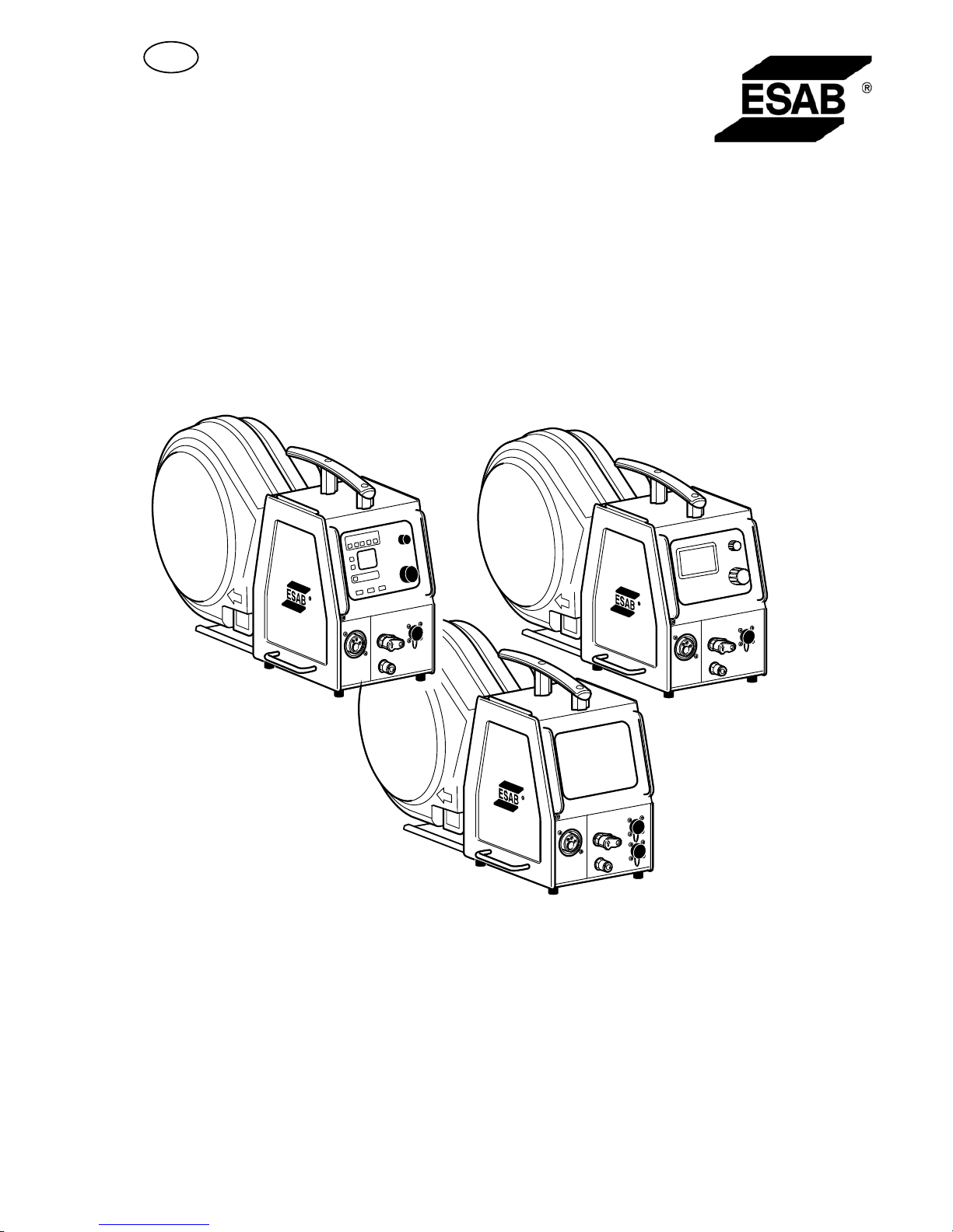
Aristo
®
/ Origo™
Feed L3004
Instruction manual
Page 2

- 2 -
TOCe
Rights reserved to alter specifications without notice.
1 DIRECTIVE 3. . . . . . . . . . . . . . . . . . . . . . . . . . . . . . . . . . . . . . . . . . . . . . . . . . . . . . . .
2 SAFETY 3. . . . . . . . . . . . . . . . . . . . . . . . . . . . . . . . . . . . . . . . . . . . . . . . . . . . . . . . . . .
3 INTRODUCTION 5. . . . . . . . . . . . . . . . . . . . . . . . . . . . . . . . . . . . . . . . . . . . . . . . . . .
3.1 Equipment 5. . . . . . . . . . . . . . . . . . . . . . . . . . . . . . . . . . . . . . . . . . . . . . . . . . . . . . . . . . . . . . . .
3.2 Control panel 5. . . . . . . . . . . . . . . . . . . . . . . . . . . . . . . . . . . . . . . . . . . . . . . . . . . . . . . . . . . . .
4 TECHNICAL DATA 6. . . . . . . . . . . . . . . . . . . . . . . . . . . . . . . . . . . . . . . . . . . . . . . . .
5 INSTALLATION 6. . . . . . . . . . . . . . . . . . . . . . . . . . . . . . . . . . . . . . . . . . . . . . . . . . . .
5.1 Lifting instructions 7. . . . . . . . . . . . . . . . . . . . . . . . . . . . . . . . . . . . . . . . . . . . . . . . . . . . . . . . .
6 OPERATION 8. . . . . . . . . . . . . . . . . . . . . . . . . . . . . . . . . . . . . . . . . . . . . . . . . . . . . . .
6.1 Connections and control devices 9. . . . . . . . . . . . . . . . . . . . . . . . . . . . . . . . . . . . . . . . . . . .
6.2 Water connection 10. . . . . . . . . . . . . . . . . . . . . . . . . . . . . . . . . . . . . . . . . . . . . . . . . . . . . . . . . .
6.3 Wire feed pressure 10. . . . . . . . . . . . . . . . . . . . . . . . . . . . . . . . . . . . . . . . . . . . . . . . . . . . . . . .
6.4 Replacing and inserting wire 10. . . . . . . . . . . . . . . . . . . . . . . . . . . . . . . . . . . . . . . . . . . . . . . .
6.5 Changing feed rollers 10. . . . . . . . . . . . . . . . . . . . . . . . . . . . . . . . . . . . . . . . . . . . . . . . . . . . . .
7 MAINTENANCE 11. . . . . . . . . . . . . . . . . . . . . . . . . . . . . . . . . . . . . . . . . . . . . . . . . . . .
7.1 Inspection and cleaning 11. . . . . . . . . . . . . . . . . . . . . . . . . . . . . . . . . . . . . . . . . . . . . . . . . . . .
8 ORDERING SPARE PARTS 11. . . . . . . . . . . . . . . . . . . . . . . . . . . . . . . . . . . . . . . . .
DIAGRAM 12. . . . . . . . . . . . . . . . . . . . . . . . . . . . . . . . . . . . . . . . . . . . . . . . . . . . . . . . . . . .
ORDERING NUMBER 14. . . . . . . . . . . . . . . . . . . . . . . . . . . . . . . . . . . . . . . . . . . . . . . . .
WEAR PARTS 16. . . . . . . . . . . . . . . . . . . . . . . . . . . . . . . . . . . . . . . . . . . . . . . . . . . . . . . .
ACCESSORIES 18. . . . . . . . . . . . . . . . . . . . . . . . . . . . . . . . . . . . . . . . . . . . . . . . . . . . . . .
Page 3

- 3 -
bm44d1ea
1 DIRECTIVE
DECLARATION OF CONFORMITY
ESAB AB, Welding Equipment, SE-695 81 Laxå, Sweden, declares that Wire feed unit Feed L3004
from serial number 613 are constructed and tested in compliance with the standard EN 60974-5 and
EN 60974-10 (Class A) in accordance with the requirements of directive (2006/95/EC) and
(2004/108/EEC).
--------------------------------------------------------------------------------------------------------------
Kent Eimbrodt
Global Director
Equipment and Automation
Laxå 2007-03-14
2 SAFETY
Users of ESAB equipment have the ultimate responsibility for ensuring that anyone who works on or
near the equipment observes all the relevant safety precautions. Safety precautions must meet the
requirements that apply to this type of equipment. The following recommendations should be ob
served in addition to the standard regulations that apply to the workplace.
All work must be carried out by trained personnel well-acquainted with the operation of the equip
ment. Incorrect operation of the equipment may lead to hazardous situations which can result in in
jury to the operator and damage to the equipment.
1. Anyone who uses the equipment must be familiar with:
S its operation
S location of emergency stops
S its function
S relevant safety precautions
S welding and cutting
2. The operator must ensure that:
S no unauthorized person is stationed within the working area of the equipment when it is
started up.
S no-one is unprotected when the arc is struck
3. The workplace must:
S be suitable for the purpose
S be free from drafts
4. Personal safety equipment
S Always wear recommended personal safety equipment, such as safety glasses, flame-proof
clothing, safety gloves.
S Do not wear loose-fitting items, such as scarves, bracelets, rings, etc., which could become
trapped or cause burns.
5. General precautions
S Make sure the return cable is connected securely.
S Work on high voltage equipment may only be carried out by a qualified electrician.
S Appropriate fire extinquishing equipment must be clearly marked and close at hand.
S Lubrication and maintenance must not be carried out on the equipment during operation.
GB
Page 4
- 4 -
bm44d1ea
WARNING
Read and understand the instruction manual before installing or operating.
Arc welding and cutting can be injurious to yourself and others. Take precausions when welding and
cutting. Ask for your employer's safety practices which should be based on manufacturers' hazard
data.
ELECTRIC SHOCK - Can kill
S Install and earth the unit in accordance with applicable standards.
S Do not touch live electrical parts or electrodes with bare skin, wet gloves or wet clothing.
S Insulate yourself from earth and the workpiece.
S Ensure your working stance is safe.
FUMES AND GASES - Can be dangerous to health
S Keep your head out of the fumes.
S Use ventilation, extraction at the arc, or both, to take fumes and gases away from your breathing zone
and the general area.
ARC RAYS - Can injure eyes and burn skin.
S Protect your eyes and body. Use the correct welding screen and filter lens and wear protective
clothing.
S Protect bystanders with suitable screens or curtains.
FIRE HAZARD
S Sparks (spatter) can cause fire. Make sure therefore that there are no inflammable materials nearby.
NOISE - Excessive noise can damage hearing
S Protect your ears. Use earmuffs or other hearing protection.
S Warn bystanders of the risk.
MALFUNCTION - Call for expert assistance in the event of malfunction.
PROTECT YOURSELF AND OTHERS!
ESAB can provide you with all necessary welding protection and accessories.
CAUTION
Read and understand the instruction manual before
installing or operating.
CAUTION
This product is solely intended for arc welding.
Dispose of electronic equipment at the recycling facility!
In observance of European Directive 2002/96/EC on Waste Electrical and Electronic
Equipment and its implementation in accordance with national law, electrical and/or
electronic equipment that has reached the end of its life must be disposed of at a
recycling facility.
As the person responsible for the equipment, it is your responsibility to obtain
information on approved collection stations.
For further information contact the nearest ESAB dealer.
GB
Page 5
- 5 -
bm44d1ea
3 INTRODUCTION
The wire feed units Feed L3004 with control panels U6, MA23 or MA23A are
intended for MIG/MAG welding with the Mig L3000i power source.
They come in different variants, see page 14.
The wire feed units contain four-wheel drive wire feed mechanisms as well as control
electronics.
They can be used together with wire on ESAB's MarathonPact, or on wire bobbin
(standard Ø 300 mm, accessory Ø 440 mm).
The wire feed unit can be installed either at the trolley for the power source, suspended
above the workplace, on a counter balance device or on the floor with or without
wheel set.
ESAB's accessories for the product can be found on page 18.
3.1 Equipment
The wire feed unit is supplied with:
S instruction manual for the wire feed unit
S instruction manual in english for the control panel
S decal with recommended wear parts.
Instruction manuals in other languages can be downloaded from the website,
www.esab.com.
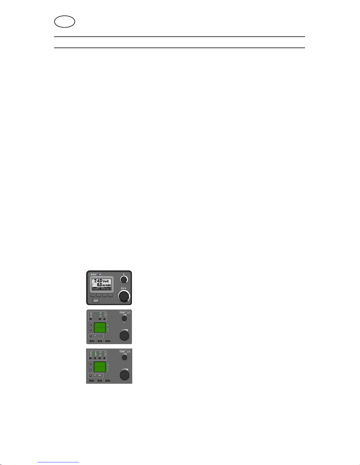
3.2 Control panel
The units are supplied with one of the following control panels:
U6
With knobs for setting the voltage and wire feed speed /
current. Other settings by pushbuttons, with text
indication on the display panel.
MA23
With knobs for setting the voltage and wire feed speed /
current. Other settings by pushbuttons.
MA23A
With knobs for setting the voltage / QSett and wire feed
speed / current. Other settings by pushbuttons.
Detailed descriptions of the control panels can be found in separate Instruction
manual.
GB
Page 6
- 6 -
bm44d1ea
4 TECHNICAL DATA
Feed L3004
Power supply 42 V 50-60 Hz
Power requirement 180 VA
Motor current I
max
3.5 A
Wire feed speed 0.8 - 25.0 m/min
Gun connection EURO
Max. diameter wire bobbin 300 mm (*440 mm)
Wire dimension
Fe
Ss
Al
Cored wire
0.6 - 1.2 mm
0.6 - 1.2 mm
1.0 - 1.2 mm
0.8 - 1.2 mm
Weight 15 kg
Dimensions (l x w x h) 690 x 275 x 420 mm
Operating temperature -10 to +40° C
Shielding gas
max pressure
All types intended for MIG/MAG welding
0.5 MPa (5 bar)
Type of cooling
max pressure
50% water / 50% mono-ethylen glycol
0.5 MPa (5 bar)
Maximum permissible load at
60% duty cycle 365 A
Enclosure class
with sealed bobbin holder
without sealed bobbin holder
IP23
IP2X
* Accessories, see page 18.
Duty cycle
The duty cycle refers to the time as a percentage of a ten-minute period that you can weld or cut at
a certain load without overloading. The duty cycle is valid for 40° C.
Enclosure class
The IP code indicates the enclosure class, i. e. the degree of protection against penetration by solid
objects or water. Equipment marked IP23 is designed for indoor and outdoor use.
Enclosure class
The IP code indicates the enclosure class, i. e. the degree of protection against penetration by solid
objects or water. Apparatus marked IP2X are intended for indoor use.
5 INSTALLATION
The installation must be executed by a professional.
GB
Page 7
- 7 -
bm44d1ea
CAUTION
This product is intended for industrial use. In a domestic environment this product may
cause radio interference. It is the user's responsibility to take adequate precautions.
WARNING
When welding in an environment with increased electrical danger, only power
sources intended for this environment may be used. These power sources are
marked with the symbol
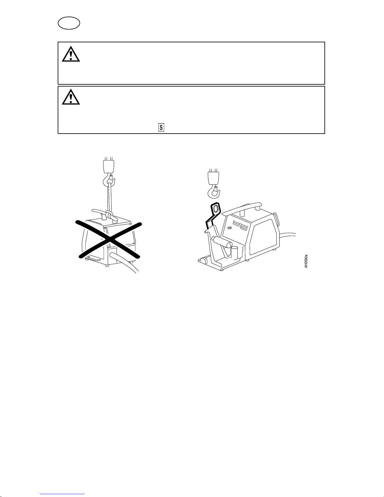
5.1 Lifting instructions
Order number for lifting eyelet can be found on page 18.
Note! If another mounting device is used, this must be electrically insulated from the
wire feed unit.
GB
Page 8
- 8 -
bm44d1ea
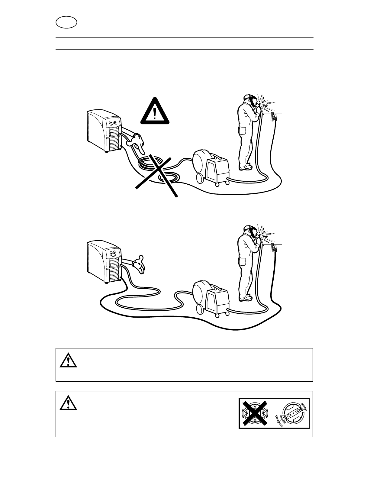
6 OPERATION
General safety regulations for the handling of the equipment can be found on
page 3. Read through before you start using the equipment!
NOTE: When moving the equipment use intended handle. Never pull on the gun.
H 0935
WARNING
Assure that the side panels are closed during operation.
WARNING
To prevent the reel from sliding off the hub: Lock the
reel in place by turning the red knob as shown on the
warning label attached next to the hub.
GB
Page 9

- 9 -
bm44d1ea
WARNING
Rotating parts can cause injury, take great care.
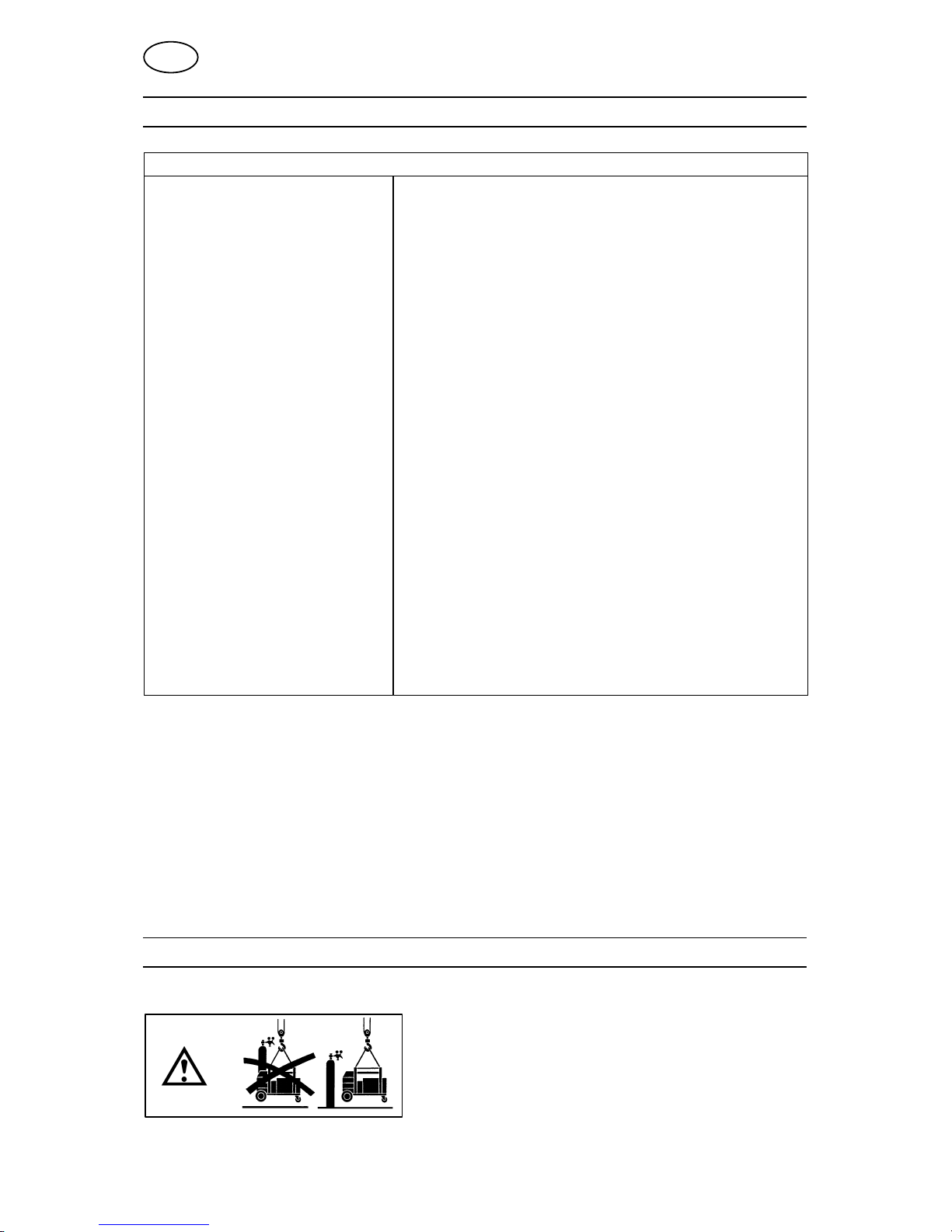
WARNING
There is a risk of tipping if the wire feed unit is fitted with a counterbalance arm.
Secure the equipment, especially if used on an uneven or sloping surface.
WARNING
Risk of crushing when replacing the wire bobbin!
Do not use safety gloves when inserting the welding wire between the feed rollers.
6.1 Connections and control devices
1 Control panel,
(see separate instruction manual)
6 Connection for welding current from power
source, (OKC)
2a2bConnection for remote control unit
Connection for U8
2
7 Connection for control cable from power
source or cooling unit
3 Connection BLUE, with ELP* for coolant to
the welding gun
8 Connection RED, for coolant to cooling
unit
4 Connection RED, for coolant from welding
gun
9 Connection for shielding gas
5 Connection for welding gun 10 Connection BLUE, for coolant from cooling
unit
Note! Coolant connections only available on certain models.
* ELP = ESAB Logic Pump, see point 6.2.
GB
Page 10

- 10 -
bm44d1ea
6.2 Water connection
The wire feed unit with water connection is equipped with a detection system ELP
(ESAB Logic Pump) which checks that the water hoses are connected. When
connecting a water-cooled welding gun, the water pump starts.
Detection only works with power sources that are equipped with ELP.
6.3 Wire feed pressure
Start by making sure that the wire moves smoothly through the wire guide. Then
set the pressure of the wire feeder's pressure rollers. It is important that the
pressure is not too great.
Fig 1 Fig 2
To check that the feed pressure is set correctly, you can feed out the wire against
an insulated object, e.g. a piece of wood.
When you hold the gun approx. 5 mm from the piece of wood (fig. 1) the feed
rollers should slip.
If you hold the gun approx. 50 mm from the piece of wood, the wire should be
fed out and bend (fig. 2).
6.4 Replacing and inserting wire
S Open the side panel.
S Disconnect the pressure sensor by folding it backwards, the pressure rollers
slide up.
S Straighten out the new wire 10-20 cm. File away burrs and sharp edges from the
end of the wire before inserting it into the wire feed unit.
S Make sure that the wire goes properly into the feed roller's track and into the
outlet nozzle and the wire guide.
S Secure the pressure sensor.
S Close the side panel.
6.5 Changing feed rollers
S Open the side panel.
S Disconnect the pressure sensor (1) by folding it
backwards, the pressure rollers slide up.
S Disconnect the pressure rollers (2) by turning the
axle (3) 1/4 turn clockwise and pulling out the axle.
The pressure rollers disconnect.
S Disconnect the feed rollers (4) by unscrewing the
nuts (5) and pulling out the rollers.
GB
Page 11

- 11 -
bm44d1ea
During installation, repeat the above in the reverse order.
Choice of tracks in the feed rollers
Turn the feed roller with the dimensioning mark for the required
track towards you.
7 MAINTENANCE
Regular maintenance is important for safe, reliable operation.
CAUTION
All guarantee undertakings from the supplier cease to apply if the customer himself
attempts any work in the product during the guarantee period in order to rectify any faults.
7.1 Inspection and cleaning
Wire feed unit
Check regularly that the wire feed unit is not clogged with dirt.
S Cleaning and replacement of the wire feed unit mechanism's worn parts should
take place at regular intervals in order to achieve trouble-free wire feed. Note
that if pre-tensioning is set too hard, this can result in abnormal wear on the
pressure roller, feed roller and wire guide.
The brake hub
The hub is adjusted when delivered, if
readjustment is required, follow the instructions
below. Adjust the brake hub so that wire is slightly
slack when wire feed stops.
S Adjusting the braking torque:
S Turn the red handle to the locked position.
S Insert a screwdriver into the springs in the hub.
Turn the springs clockwise to reduce the braking torque
Turn the springs counterclockwise to increase the braking torque. NB: Turn
both springs through the same amount.
Welding gun
S Cleaning and replacement of the welding gun's wear parts should take place at
regular intervals in order to achieve trouble-free wire feed. Blow the wire guide
clean regularly and clean the contact tip.
8 ORDERING SPARE PARTS
Feed L3004 is designed and tested in accordance with the international and European
standards 60974-5 and 60974-10. It is the obligation of the service unit which has car
ried out the service or repair work to make sure that the product still conforms to the
said standard.
Spare parts may be ordered through your nearest ESAB dealer, see the last page of
this publication.
GB
Page 12

Edition 110308
Diagram
- 12 -
bm44e
Page 13

Edition 110308
- 13 -
bm44e
Page 14

Feed L3004
Edition 110308
Ordering number
- 14 -
bm44o
Ordering no. Denomination Type
0458 806 586 Wire feed unit Aristot Feed L3004, U6
0458 806 596 Wire feed unit Aristot Feed L3004w, U6 with water cooling
0459 116 597 Wire feed unit Origot Feed L3004w, MA23 with water cooling
0459 116 598 Wire feed unit Origot Feed L3004w, MA23A with water cooling
0459 839 001 Spare parts list Feed L3004
0459 287 Instruction manual Control panel U6
0459 912 Instruction manual Control panel MA23 and MA23A
Instruction manuals and the spare parts list are available on the Internet at www.esab.com
Page 15

- 15 -
p
Page 16

Feed L3004
Wear parts
- 16 -
bm44w
Item Ordering no. Denomination Wire type Wire dimensions
HI 1 0455 072 002
0456 615 001
Intermediate nozzle
Intermediate nozzle
Fe, Ss & cored
Al
HI 2 0469 837 880
0469 837 881
Outlet nozzle
Outlet nozzle
Fe, Ss & cored
Al
Ø 2.0 mm steel for 0.6-1.2 mm
Ø 2.0 mm plastic for 0.8-1.2 mm
HI 3 0191 496 114 Key
HI 4 0215 701 007 Locking washer
HI 5a 0459 440 001 Motor gear euro
Item Ordering no. Denomination Wire type Wire dimensions Groove
typ
Roller
markings
HI 5b 0459 052 001 Feed/pressure rollers Fe, Ss & cored Ø 0.6 & 0.8 mm V
0459 052 002 Feed/pressure rollers Fe, Ss & cored Ø 0.8 & 0.9/1.0 mm V
0459 052 003 Feed/pressure rollers Fe, Ss & cored Ø 0.9/1.0 & 1.2 mm V
0.6 S2 & 0.8 S2
0.8 S2 & 1.0 S2
0.9/1.0 S2 & 1.2 S2
0458 825 001 Feed/pressure rollers Cored Ø 0.9/1.0 & 1.2 mm V-Knurled 1.0 R2 & 1.2 R2
0458 824 001 Feed/pressure rollers Al Ø 0.8 & 0.9/1.0 mm U 0.8 A2 & 1.0 A2
0458 824 002 Feed/pressure rollers Al Ø 1.0 & 1.2 mm U 1.0 A2 & 1.2 A2
0458 824 003 Feed/pressure rollers Al Ø 1.2 mm U 1.2 A2
Use only pressure and feed rollers marked A2, R2 or S2.
The rollers are marked with wire dimension in mm, some are also marked with inch.
Item Ordering no. Denomination Notes
HI 6 Washer Ø 16/5x1
HI 7 Screw M4x12
HI 8 Screw M6x12
HI 9 Washer Ø 16/8.4x1.5
HI 10 0469 838 001 Cover
HI 11 0458 722 880 Axle and Nut
HI 12 0459 441 880 Gear adapter
HI 13 0455 049 001 Inlet nozzle
HI 14 0458 999 001 Shaft
HI 15 Nut M10
HI 16 0458 748 002 Insulating washer
HI 17 0458 748 001 Insulating bushing
HD = Heavy Duty
Item Ordering no. Denomination Notes Wire dimensions
HI 18 0156 602 001
0332 318 001
Inlet nozzle
Inlet nozzle (HD)
Fe, Ss, Al & Cored
Fe, Ss & Cored
Ø 2 mm plastic for 0.6-1.2 mm
Ø 2.4 mm steel for 1.2 mm
Welding with aluminium wire
In order to weld with aluminium wire, proper rollers, nozzles and liners for aluminium wire MUST be
used, It is recommended to use 3 m long welding gun for aluminium wire, equipped with appropriate
wear parts.
Page 17

Feed L3004
- 17 -
bm44w
Page 18

Feed L3004
Accessories
- 18 -
bm44a11a
1 Bobbin cover, plastic Ø 300mm . . . . . . . . . . . 0458 674 880
1 Bobbin cover, metal Ø 300mm . . . . . . . . . . . . . 0459 431 880
12Bobbin holder . . . . . . . . . . . . . . . . . . . . . . . . . . .
Adapter for 5 kg bobbin . . . . . . . . . . . . . . . . . . . .
0458 704 880
0455 410 001
1 Adapter for 440 mm bobbin . . . . . . . . . . . . . . . .
Note! The wire feed unit must be placed on the
floor when this adaptor i used.
0459 233 880
12Lifting eye . . . . . . . . . . . . . . . . . . . . . . . . . . . . . . .
Quick connector MarathonPact . . . . . . . . . . .
0458 706 880
F102 440 880
Page 19

Feed L3004
- 19 -
bm44a11a
1
2
3
Turning piece . . . . . . . . . . . . . . . . . . . . . . . . . . . .
Guide pin . . . . . . . . . . . . . . . . . . . . . . . . . . . . . . . .
Quick connector MarathonPact . . . . . . . . . . .
0458 703 880
0349 302 303
F102 440 880
1 Wheel kit . . . . . . . . . . . . . . . . . . . . . . . . . . . . . . . . 0458 707 880
1 Strain relief for welding gun . . . . . . . . . . . . . . 0457 341 881
Strain relief bracket for connection set . . . . 0459 234 880
Connection set 50mm
2
1.7 m . . . . . . . . . . . . . . . . . . . . . . . . . . . . . . . . . . . .
5 m . . . . . . . . . . . . . . . . . . . . . . . . . . . . . . . . . . . . . .
10 m . . . . . . . . . . . . . . . . . . . . . . . . . . . . . . . . . . . . .
15 m . . . . . . . . . . . . . . . . . . . . . . . . . . . . . . . . . . . . .
Connection set water 50mm
2
1.7 m . . . . . . . . . . . . . . . . . . . . . . . . . . . . . . . . . . . .
5 m . . . . . . . . . . . . . . . . . . . . . . . . . . . . . . . . . . . . . .
10 m . . . . . . . . . . . . . . . . . . . . . . . . . . . . . . . . . . . . .
15 m . . . . . . . . . . . . . . . . . . . . . . . . . . . . . . . . . . . . .
0456 528 580
0456 528 581
0456 528 582
0456 528 583
0456 528 590
0456 528 591
0456 528 592
0456 528 593
Page 20

Feed L3004
- 20 -
bm44a11a
Counter balance device . . . . . . . . . . . . . . . . . . .
(includes mast and counter balance)
0458 705 880
Remote control adapter RA23 23 pole . . . . .
For connecting welding gun with RS3 program
selector to CAN based equipment.
0459 491 911
Remote control unit MTA1 CAN . . . . . . . . . . .
MIG/MAG: wire feed speed and voltage MMA:
current and arc force
TIG: current, pulse and background current
0459 491 880
Remote control unit M1 10Prog CAN . . . . . . .
Choice of on of 10 programs
MIG/MAG: voltage deviation
TIG and MMA: current deviation
0459 491 882
Remote cable CAN 4 pole - 12 pole
5 m . . . . . . . . . . . . . . . . . . . . . . . . . . . . . . . . . . . . . .
0.25 m . . . . . . . . . . . . . . . . . . . . . . . . . . . . . . . . . . .
0459 554 880
0459 554 884
Page 21

Feed L3004
- 21 -
bm44a11a
Welding gun MXH 400w PP
6.0 m . . . . . . . . . . . . . . . . . . . . . . . . . . . . . . . . . . . .
10.0 m . . . . . . . . . . . . . . . . . . . . . . . . . . . . . . . . . . .
Welding gun MXH 300 PP
6.0 m . . . . . . . . . . . . . . . . . . . . . . . . . . . . . . . . . . . .
10.0 m . . . . . . . . . . . . . . . . . . . . . . . . . . . . . . . . . . .
0700 200 015
0700 200 016
0700 200 017
0700 200 018
Remote adapter kit
For MXH 400w PP . . . . . . . . . . . . . . . . . . . . . . . . 0459 681 881
Connection kit without wire feed speed adjustment
For MXH 400w PP . . . . . . . . . . . . . . . . . . . . . . . . 0459 020 883
Welding torch
Type
Ordering no. Max welding current
Wire
dimensions
Hose length Shielding gas
3 m 4.5 m CO
2
Mix Ar
PSF 250 0368 100 882 0368 100 883 250A 60% 225A 60% 0.6 - 1.0
PSF 250 C 0468 410 882 0468 410 883 250A 60% 225A 60% 0.6 - 1.0
PSF 305 0458 401 880 0458 401 881 315A 60% 285A 60% 0.8 - 1.2
PSF 315 CLD 0468 410 885 0468 410 886 315A 60% 285A 60% 0.8 - 1.2
PSF 405 0458 401 882 0458 401 883 380A 60% 325A 60% 0.8 - 1.6
PSF 405 C 0458 499 882 0458 499 883 380A 60% 325A 60% 1.0 - 1.6
PSF 405 RS3 0458 401 892 0458 401 893 380A 60% 325A 60% 0.8 - 1.6
PSF 405 C RS3 - 0458 499 889 380A 60% 325A 60% 1.0 - 1.6
PSF 410 CW 0458 450 880 0458 450 881 380A 100% 325A 100% 0.8 - 1.6
PSF 410 W 0458 400 882 0458 400 883 400A 100% 350A 100% 0.8 - 1.6
PSF 410 CW RS3 0458 450 884 0458 450 885 380A 100% 325A 100% 0.8 - 1.6
PSF 410 W RS3 0458 400 898 0458 400 899 400A 100% 350A 100% 0.8 - 1.6
= Self cooled
C = Smoke exhausters, Centrovac
LD = Smaller, Light duty
W = Water cooled
RS3 = 3-step program switch for selecting preset programs.
Page 22

- 22 -
notes
NOTES
.............................................................................................................................................................
.............................................................................................................................................................
.............................................................................................................................................................
.............................................................................................................................................................
.............................................................................................................................................................
.............................................................................................................................................................
.............................................................................................................................................................
.............................................................................................................................................................
.............................................................................................................................................................
.............................................................................................................................................................
.............................................................................................................................................................
.............................................................................................................................................................
.............................................................................................................................................................
.............................................................................................................................................................
.............................................................................................................................................................
.............................................................................................................................................................
.............................................................................................................................................................
.............................................................................................................................................................
.............................................................................................................................................................
.............................................................................................................................................................
.............................................................................................................................................................
.............................................................................................................................................................
.............................................................................................................................................................
.............................................................................................................................................................
.............................................................................................................................................................
.............................................................................................................................................................
.............................................................................................................................................................
.............................................................................................................................................................
.............................................................................................................................................................
.............................................................................................................................................................
.............................................................................................................................................................
Page 23

- 23 -
notes
NOTES
.............................................................................................................................................................
.............................................................................................................................................................
.............................................................................................................................................................
.............................................................................................................................................................
.............................................................................................................................................................
.............................................................................................................................................................
.............................................................................................................................................................
.............................................................................................................................................................
.............................................................................................................................................................
.............................................................................................................................................................
.............................................................................................................................................................
.............................................................................................................................................................
.............................................................................................................................................................
.............................................................................................................................................................
.............................................................................................................................................................
.............................................................................................................................................................
.............................................................................................................................................................
.............................................................................................................................................................
.............................................................................................................................................................
.............................................................................................................................................................
.............................................................................................................................................................
.............................................................................................................................................................
.............................................................................................................................................................
.............................................................................................................................................................
.............................................................................................................................................................
.............................................................................................................................................................
.............................................................................................................................................................
.............................................................................................................................................................
.............................................................................................................................................................
.............................................................................................................................................................
.............................................................................................................................................................
Page 24

ESAB AB
SE-695 81 LAXÅ
SWEDEN
Phone +46 584 81 000
www.esab.com
110210
ESAB subsidiaries and representative offices
Europe
AUSTRIA
ESAB Ges.m.b.H
Vienna-Liesing
Tel: +43 1 888 25 11
Fax: +43 1 888 25 11 85
BELGIUM
S.A. ESAB N.V.
Brussels
Tel: +32 2 745 11 00
Fax: +32 2 745 11 28
BULGARIA
ESAB Kft Representative Office
Sofia
Tel/Fax: +359 2 974 42 88
THE CZECH REPUBLIC
ESAB VAMBERK s.r.o.
Vamberk
Tel: +420 2 819 40 885
Fax: +420 2 819 40 120
DENMARK
Aktieselskabet ESAB
Herlev
Tel: +45 36 30 01 11
Fax: +45 36 30 40 03
FINLAND
ESAB Oy
Helsinki
Tel: +358 9 547 761
Fax: +358 9 547 77 71
FRANCE
ESAB France S.A.
Cergy Pontoise
Tel: +33 1 30 75 55 00
Fax: +33 1 30 75 55 24
GERMANY
ESAB GmbH
Solingen
Tel: +49 212 298 0
Fax: +49 212 298 218
GREAT BRITAIN
ESAB Group (UK) Ltd
Waltham Cross
Tel: +44 1992 76 85 15
Fax: +44 1992 71 58 03
ESAB Automation Ltd
Andover
Tel: +44 1264 33 22 33
Fax: +44 1264 33 20 74
HUNGARY
ESAB Kft
Budapest
Tel: +36 1 20 44 182
Fax: +36 1 20 44 186
ITALY
ESAB Saldatura S.p.A.
Bareggio (Mi)
Tel: +39 02 97 96 8.1
Fax: +39 02 97 96 87 01
THE NETHERLANDS
ESAB Nederland B.V.
Amersfoort
Tel: +31 33 422 35 55
Fax: +31 33 422 35 44
NORWAY
AS ESAB
Larvik
Tel: +47 33 12 10 00
Fax: +47 33 11 52 03
POLAND
ESAB Sp.zo.o.
Katowice
Tel: +48 32 351 11 00
Fax: +48 32 351 11 20
PORTUGAL
ESAB Lda
Lisbon
Tel: +351 8 310 960
Fax: +351 1 859 1277
ROMANIA
ESAB Romania Trading SRL
Bucharest
Tel: +40 316 900 600
Fax: +40 316 900 601
RUSSIA
LLC ESAB
Moscow
Tel: +7 (495) 663 20 08
Fax: +7 (495) 663 20 09
SLOVAKIA
ESAB Slovakia s.r.o.
Bratislava
Tel: +421 7 44 88 24 26
Fax: +421 7 44 88 87 41
SPAIN
ESAB Ibérica S.A.
Alcalá de Henares (MADRID)
Tel: +34 91 878 3600
Fax: +34 91 802 3461
SWEDEN
ESAB Sverige AB
Gothenburg
Tel: +46 31 50 95 00
Fax: +46 31 50 92 22
ESAB international AB
Gothenburg
Tel: +46 31 50 90 00
Fax: +46 31 50 93 60
SWITZERLAND
ESAB AG
Dietikon
Tel: +41 1 741 25 25
Fax: +41 1 740 30 55
UKRAINE
ESAB Ukraine LLC
Kiev
Tel: +38 (044) 501 23 24
Fax: +38 (044) 575 21 88
North and South America
ARGENTINA
CONARCO
Buenos Aires
Tel: +54 11 4 753 4039
Fax: +54 11 4 753 6313
BRAZIL
ESAB S.A.
Contagem-MG
Tel: +55 31 2191 4333
Fax: +55 31 2191 4440
CANADA
ESAB Group Canada Inc.
Missisauga, Ontario
Tel: +1 905 670 02 20
Fax: +1 905 670 48 79
MEXICO
ESAB Mexico S.A.
Monterrey
Tel: +52 8 350 5959
Fax: +52 8 350 7554
USA
ESAB Welding & Cutting Products
Florence, SC
Tel: +1 843 669 44 11
Fax: +1 843 664 57 48
Asia/Pacific
CHINA
Shanghai ESAB A/P
Shanghai
Tel: +86 21 2326 3000
Fax: +86 21 6566 6622
INDIA
ESAB India Ltd
Calcutta
Tel: +91 33 478 45 17
Fax: +91 33 468 18 80
INDONESIA
P.T. ESABindo Pratama
Jakarta
Tel: +62 21 460 0188
Fax: +62 21 461 2929
JAPAN
ESAB Japan
Tokyo
Tel: +81 45 670 7073
Fax: +81 45 670 7001
MALAYSIA
ESAB (Malaysia) Snd Bhd
USJ
Tel: +603 8023 7835
Fax: +603 8023 0225
SINGAPORE
ESAB Asia/Pacific Pte Ltd
Singapore
Tel: +65 6861 43 22
Fax: +65 6861 31 95
SOUTH KOREA
ESAB SeAH Corporation
Kyungnam
Tel: +82 55 269 8170
Fax: +82 55 289 8864
UNITED ARAB EMIRATES
ESAB Middle East FZE
Dubai
Tel: +971 4 887 21 11
Fax: +971 4 887 22 63
Africa
EGYPT
ESAB Egypt
Dokki-Cairo
Tel: +20 2 390 96 69
Fax: +20 2 393 32 13
SOUTH AFRICA
ESAB Africa Welding & Cutting Ltd
Durbanvill 7570 - Cape Town
Tel: +27 (0)21 975 8924
Distributors
For addresses and phone
numbers to our distributors in
other countries, please visit our
home page
www.esab.com
 Loading...