

GB
Valid for serial no. 613-xxx-xxxx0459 813 101 GB 110308
Aristo
®
/ Origo™
Feed L3004
Instruction manual

- 2 -
TOCe
Rights reserved to alter specifications without notice.
1 DIRECTIVE 3. . . . . . . . . . . . . . . . . . . . . . . . . . . . . . . . . . . . . . . . . . . . . . . . . . . . . . . .
2 SAFETY 3. . . . . . . . . . . . . . . . . . . . . . . . . . . . . . . . . . . . . . . . . . . . . . . . . . . . . . . . . . .
3 INTRODUCTION 5. . . . . . . . . . . . . . . . . . . . . . . . . . . . . . . . . . . . . . . . . . . . . . . . . . .
3.1 Equipment 5. . . . . . . . . . . . . . . . . . . . . . . . . . . . . . . . . . . . . . . . . . . . . . . . . . . . . . . . . . . . . . . .
3.2 Control panel 5. . . . . . . . . . . . . . . . . . . . . . . . . . . . . . . . . . . . . . . . . . . . . . . . . . . . . . . . . . . . .
4 TECHNICAL DATA 6. . . . . . . . . . . . . . . . . . . . . . . . . . . . . . . . . . . . . . . . . . . . . . . . .
5 INSTALLATION 6. . . . . . . . . . . . . . . . . . . . . . . . . . . . . . . . . . . . . . . . . . . . . . . . . . . .
5.1 Lifting instructions 7. . . . . . . . . . . . . . . . . . . . . . . . . . . . . . . . . . . . . . . . . . . . . . . . . . . . . . . . .
6 OPERATION 8. . . . . . . . . . . . . . . . . . . . . . . . . . . . . . . . . . . . . . . . . . . . . . . . . . . . . . .
6.1 Connections and control devices 9. . . . . . . . . . . . . . . . . . . . . . . . . . . . . . . . . . . . . . . . . . . .
6.2 Water connection 10. . . . . . . . . . . . . . . . . . . . . . . . . . . . . . . . . . . . . . . . . . . . . . . . . . . . . . . . . .
6.3 Wire feed pressure 10. . . . . . . . . . . . . . . . . . . . . . . . . . . . . . . . . . . . . . . . . . . . . . . . . . . . . . . .
6.4 Replacing and inserting wire 10. . . . . . . . . . . . . . . . . . . . . . . . . . . . . . . . . . . . . . . . . . . . . . . .
6.5 Changing feed rollers 10. . . . . . . . . . . . . . . . . . . . . . . . . . . . . . . . . . . . . . . . . . . . . . . . . . . . . .
7 MAINTENANCE 11. . . . . . . . . . . . . . . . . . . . . . . . . . . . . . . . . . . . . . . . . . . . . . . . . . . .
7.1 Inspection and cleaning 11. . . . . . . . . . . . . . . . . . . . . . . . . . . . . . . . . . . . . . . . . . . . . . . . . . . .
8 ORDERING SPARE PARTS 11. . . . . . . . . . . . . . . . . . . . . . . . . . . . . . . . . . . . . . . . .
DIAGRAM 12. . . . . . . . . . . . . . . . . . . . . . . . . . . . . . . . . . . . . . . . . . . . . . . . . . . . . . . . . . . .
ORDERING NUMBER 14. . . . . . . . . . . . . . . . . . . . . . . . . . . . . . . . . . . . . . . . . . . . . . . . .
WEAR PARTS 16. . . . . . . . . . . . . . . . . . . . . . . . . . . . . . . . . . . . . . . . . . . . . . . . . . . . . . . .
ACCESSORIES 18. . . . . . . . . . . . . . . . . . . . . . . . . . . . . . . . . . . . . . . . . . . . . . . . . . . . . . .

- 3 -
bm44d1ea
1 DIRECTIVE
DECLARATION OF CONFORMITY
ESAB AB, Welding Equipment, SE-695 81 Laxå, Sweden, declares that Wire feed unit Feed L3004
from serial number 613 are constructed and tested in compliance with the standard EN 60974-5 and
EN 60974-10 (Class A) in accordance with the requirements of directive (2006/95/EC) and
(2004/108/EEC).
--------------------------------------------------------------------------------------------------------------
Kent Eimbrodt
Global Director
Equipment and Automation
Laxå 2007-03-14
2 SAFETY
Users of ESAB equipment have the ultimate responsibility for ensuring that anyone who works on or
near the equipment observes all the relevant safety precautions. Safety precautions must meet the
requirements that apply to this type of equipment. The following recommendations should be ob
served in addition to the standard regulations that apply to the workplace.
All work must be carried out by trained personnel well-acquainted with the operation of the equip
ment. Incorrect operation of the equipment may lead to hazardous situations which can result in in
jury to the operator and damage to the equipment.
1. Anyone who uses the equipment must be familiar with:
S its operation
S location of emergency stops
S its function
S relevant safety precautions
S welding and cutting
2. The operator must ensure that:
S no unauthorized person is stationed within the working area of the equipment when it is
started up.
S no-one is unprotected when the arc is struck
3. The workplace must:
S be suitable for the purpose
S be free from drafts
4. Personal safety equipment
S Always wear recommended personal safety equipment, such as safety glasses, flame-proof
clothing, safety gloves.
S Do not wear loose-fitting items, such as scarves, bracelets, rings, etc., which could become
trapped or cause burns.
5. General precautions
S Make sure the return cable is connected securely.
S Work on high voltage equipment may only be carried out by a qualified electrician.
S Appropriate fire extinquishing equipment must be clearly marked and close at hand.
S Lubrication and maintenance must not be carried out on the equipment during operation.
GB
- 4 -
bm44d1ea
WARNING
Read and understand the instruction manual before installing or operating.
Arc welding and cutting can be injurious to yourself and others. Take precausions when welding and
cutting. Ask for your employer's safety practices which should be based on manufacturers' hazard
data.
ELECTRIC SHOCK - Can kill
S Install and earth the unit in accordance with applicable standards.
S Do not touch live electrical parts or electrodes with bare skin, wet gloves or wet clothing.
S Insulate yourself from earth and the workpiece.
S Ensure your working stance is safe.
FUMES AND GASES - Can be dangerous to health
S Keep your head out of the fumes.
S Use ventilation, extraction at the arc, or both, to take fumes and gases away from your breathing zone
and the general area.
ARC RAYS - Can injure eyes and burn skin.
S Protect your eyes and body. Use the correct welding screen and filter lens and wear protective
clothing.
S Protect bystanders with suitable screens or curtains.
FIRE HAZARD
S Sparks (spatter) can cause fire. Make sure therefore that there are no inflammable materials nearby.
NOISE - Excessive noise can damage hearing
S Protect your ears. Use earmuffs or other hearing protection.
S Warn bystanders of the risk.
MALFUNCTION - Call for expert assistance in the event of malfunction.
PROTECT YOURSELF AND OTHERS!
ESAB can provide you with all necessary welding protection and accessories.
CAUTION
Read and understand the instruction manual before
installing or operating.
CAUTION
This product is solely intended for arc welding.
Dispose of electronic equipment at the recycling facility!
In observance of European Directive 2002/96/EC on Waste Electrical and Electronic
Equipment and its implementation in accordance with national law, electrical and/or
electronic equipment that has reached the end of its life must be disposed of at a
recycling facility.
As the person responsible for the equipment, it is your responsibility to obtain
information on approved collection stations.
For further information contact the nearest ESAB dealer.
GB
- 5 -
bm44d1ea
3 INTRODUCTION
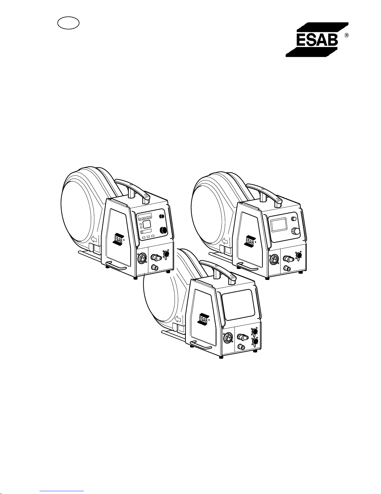
The wire feed units Feed L3004 with control panels U6, MA23 or MA23A are
intended for MIG/MAG welding with the Mig L3000i power source.
They come in different variants, see page 14.
The wire feed units contain four-wheel drive wire feed mechanisms as well as control
electronics.
They can be used together with wire on ESAB's MarathonPact, or on wire bobbin
(standard Ø 300 mm, accessory Ø 440 mm).
The wire feed unit can be installed either at the trolley for the power source, suspended
above the workplace, on a counter balance device or on the floor with or without
wheel set.
ESAB's accessories for the product can be found on page 18.
3.1 Equipment
The wire feed unit is supplied with:
S instruction manual for the wire feed unit
S instruction manual in english for the control panel
S decal with recommended wear parts.
Instruction manuals in other languages can be downloaded from the website,
www.esab.com.
3.2 Control panel
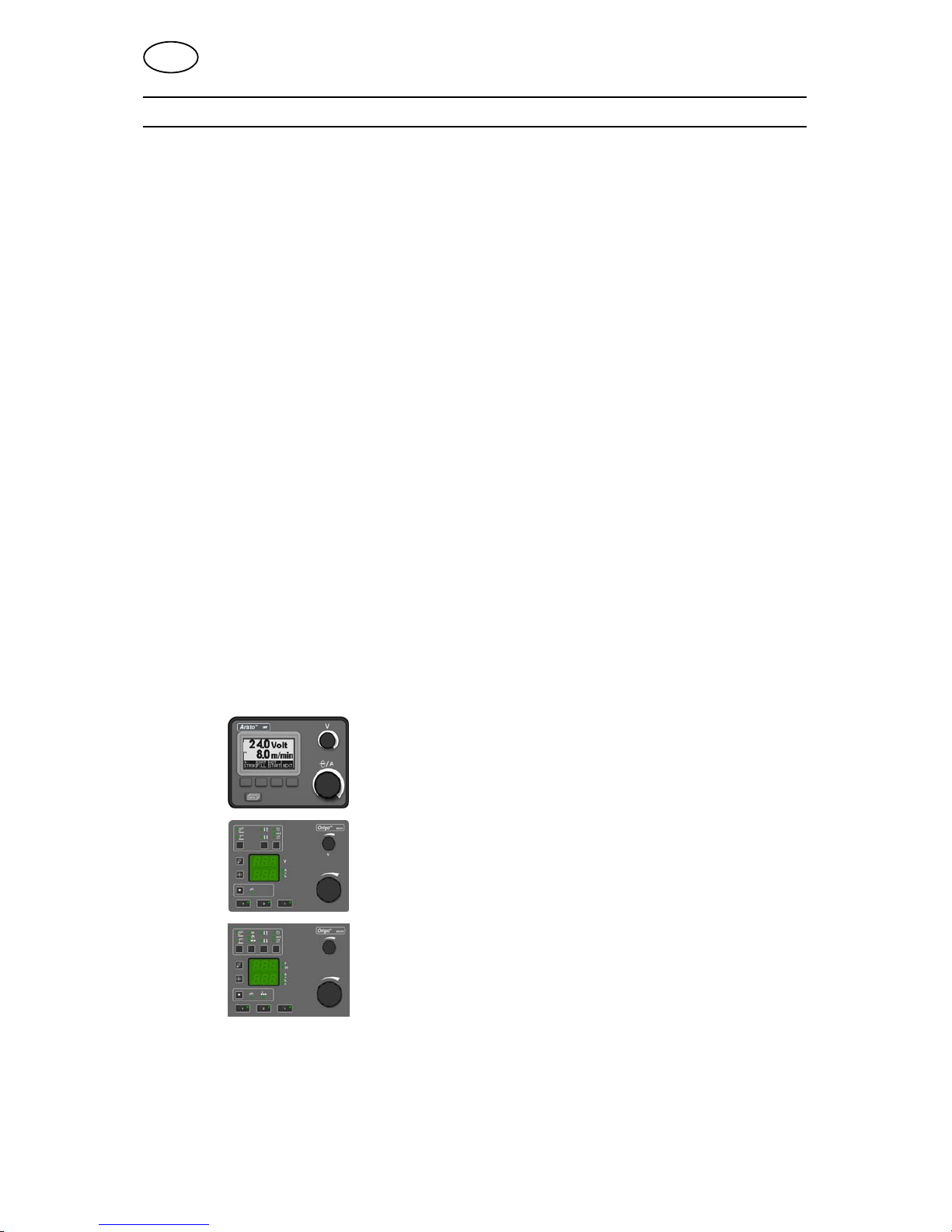
The units are supplied with one of the following control panels:
U6
With knobs for setting the voltage and wire feed speed /
current. Other settings by pushbuttons, with text
indication on the display panel.
MA23
With knobs for setting the voltage and wire feed speed /
current. Other settings by pushbuttons.
MA23A
With knobs for setting the voltage / QSett and wire feed
speed / current. Other settings by pushbuttons.
Detailed descriptions of the control panels can be found in separate Instruction
manual.
GB
- 6 -
bm44d1ea
4 TECHNICAL DATA
Feed L3004
Power supply 42 V 50-60 Hz
Power requirement 180 VA
Motor current I
max
3.5 A
Wire feed speed 0.8 - 25.0 m/min
Gun connection EURO
Max. diameter wire bobbin 300 mm (*440 mm)
Wire dimension
Fe
Ss
Al
Cored wire
0.6 - 1.2 mm
0.6 - 1.2 mm
1.0 - 1.2 mm
0.8 - 1.2 mm
Weight 15 kg
Dimensions (l x w x h) 690 x 275 x 420 mm
Operating temperature -10 to +40° C
Shielding gas
max pressure
All types intended for MIG/MAG welding
0.5 MPa (5 bar)
Type of cooling
max pressure
50% water / 50% mono-ethylen glycol
0.5 MPa (5 bar)
Maximum permissible load at
60% duty cycle 365 A
Enclosure class
with sealed bobbin holder
without sealed bobbin holder
IP23
IP2X
* Accessories, see page 18.
Duty cycle
The duty cycle refers to the time as a percentage of a ten-minute period that you can weld or cut at
a certain load without overloading. The duty cycle is valid for 40° C.
Enclosure class
The IP code indicates the enclosure class, i. e. the degree of protection against penetration by solid
objects or water. Equipment marked IP23 is designed for indoor and outdoor use.
Enclosure class
The IP code indicates the enclosure class, i. e. the degree of protection against penetration by solid
objects or water. Apparatus marked IP2X are intended for indoor use.
5 INSTALLATION
The installation must be executed by a professional.
GB
- 7 -
bm44d1ea
CAUTION
This product is intended for industrial use. In a domestic environment this product may
cause radio interference. It is the user's responsibility to take adequate precautions.
WARNING
When welding in an environment with increased electrical danger, only power
sources intended for this environment may be used. These power sources are
marked with the symbol
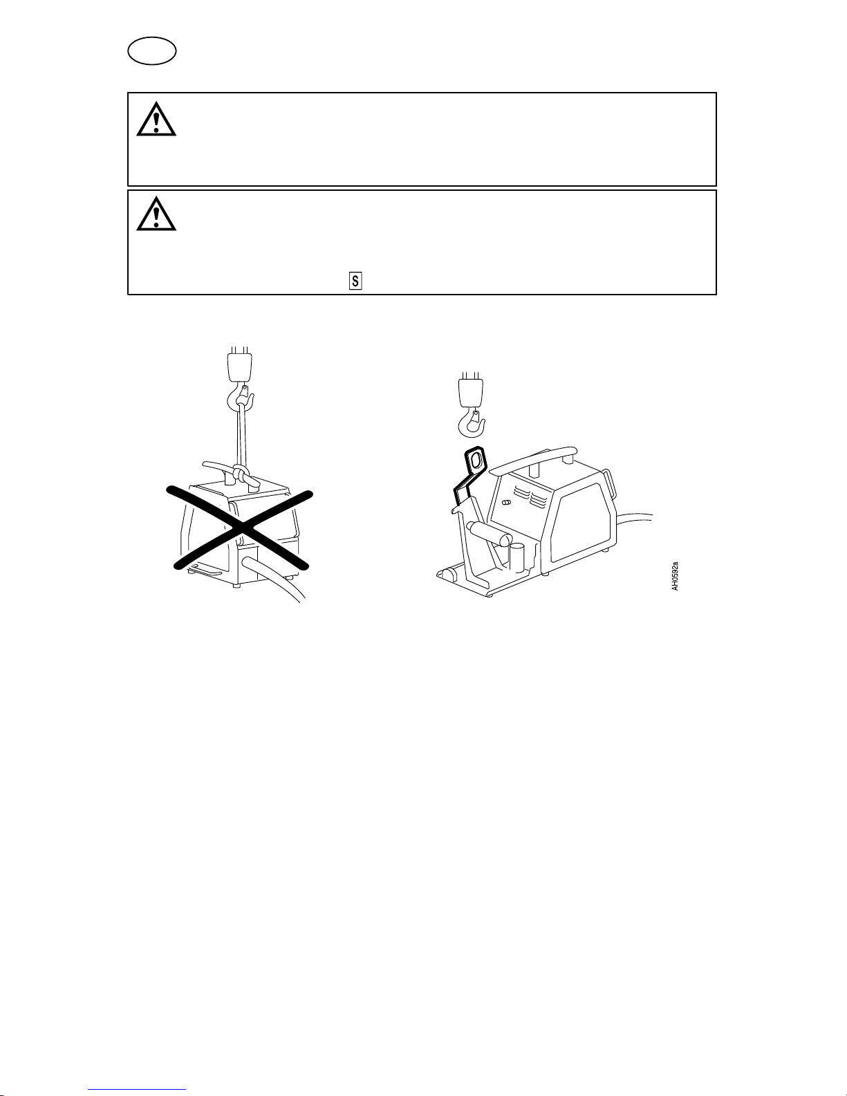
5.1 Lifting instructions
Order number for lifting eyelet can be found on page 18.
Note! If another mounting device is used, this must be electrically insulated from the
wire feed unit.
GB
- 8 -
bm44d1ea
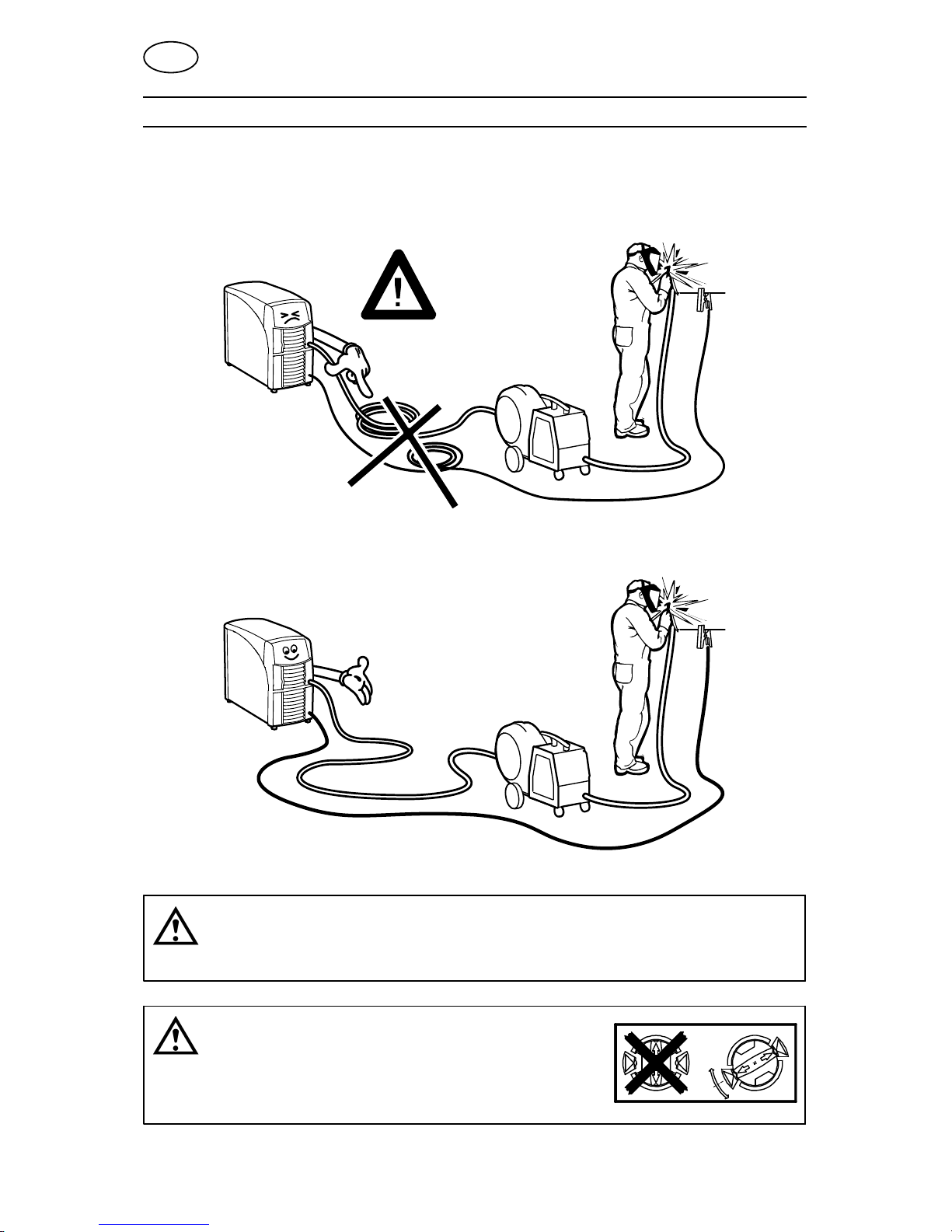
6 OPERATION
General safety regulations for the handling of the equipment can be found on
page 3. Read through before you start using the equipment!
NOTE: When moving the equipment use intended handle. Never pull on the gun.
H 0935
WARNING
Assure that the side panels are closed during operation.
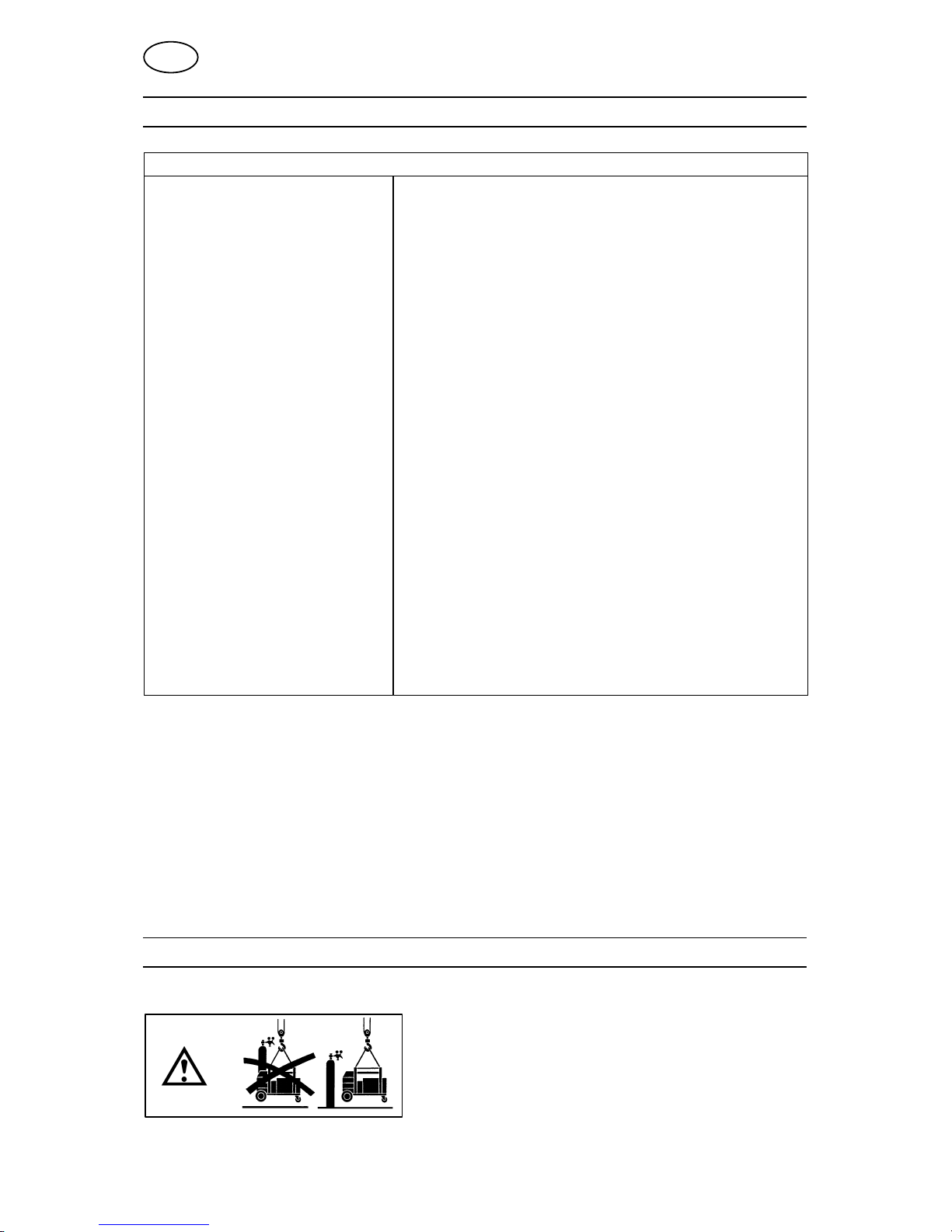
WARNING
To prevent the reel from sliding off the hub: Lock the
reel in place by turning the red knob as shown on the
warning label attached next to the hub.
GB
 Loading...