


Aristo®, Origo™
Feed3004, Feed4804
Instruction manual
0444 408 301 GB 20210316
Valid for: 3004 from serial no. 540-, 4804 from serial no.
745-xxx-xxxx


TABLE OF CONTENTS
1
SAFETY
1.1 Meaning of symbols
1.2 Safety precautions
2
INTRODUCTION
2.1 Equipment
2.2 Control panel
3
TECHNICAL DATA
4
INSTALLATION
4.1 Lifting instructions
5
OPERATION
5.1 Connections and control devices
5.2 Water connections
5.3 Wire feed pressure
5.4 Replacing and inserting Feed 3004 wire
5.5 Replacing and inserting Feed 4804 wire
5.6 Changing feed rollers on Feed 3004
5.7 Changing feed rollers on Feed 4804
.......................................................................................................
...............................................................................
.................................................................................
..........................................................................................
...............................................................................................
..........................................................................................
......................................................................................
............................................................................................
.................................................................................
................................................................................................
.................................................................................
.................................................................................
.........................................................
..............................................
..............................................
.....................................................
.....................................................
5
5
5
8
8
8
10
11
11
12
13
13
13
14
14
15
15
6
MAINTENANCE
6.1 Inspection and cleaning
7
ORDERING SPARE PARTS
DIAGRAM
WEAR PARTS
............................................................................................................
......................................................................................................
ORDERING NUMBERS
ACCESSORIES
...........................................................................................
.......................................................................................
...................................................................................................
.........................................................................
........................................................................
16
16
17
18
20
28
29
Rights reserved to alter specifications without notice.
0444 408 301 © ESAB AB 2021
1 SAFETY
1 SAFETY
1.1 Meaning of symbols
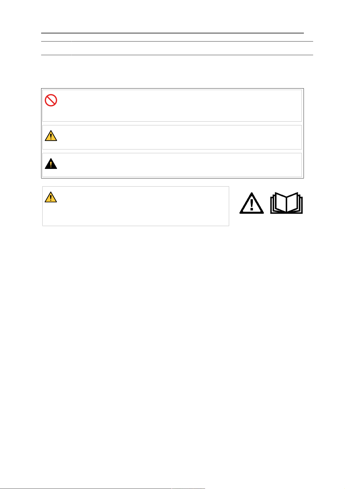
As used throughout this manual: Means Attention! Be Alert!
DANGER!
Means immediate hazards which, if not avoided, will result in immediate,
serious personal injury or loss of life.
WARNING!
Means potential hazards which could result in personal injury or loss of life.
CAUTION!
Means hazards which could result in minor personal injury.
WARNING!
Before use, read and understand the instruction manual
and follow all labels, employer´s safety practices and
Safety Data Sheets (SDSs).
1.2 Safety precautions
Users of ESAB equipment have the ultimate responsibility for ensuring that anyone who
works on or near the equipment observes all the relevant safety precautions. Safety
precautions must meet the requirements that apply to this type of equipment. The following
recommendations should be observed in addition to the standard regulations that apply to
the workplace.
All work must be carried out by trained personnel well-acquainted with the operation of the
equipment. Incorrect operation of the equipment may lead to hazardous situations which can
result in injury to the operator and damage to the equipment.
1. Anyone who uses the equipment must be familiar with:
○ its operation
○ location of emergency stops
○ its function
○ relevant safety precautions
○ welding and cutting or other applicable operation of the equipment
2. The operator must ensure that:
○ no unauthorised person is stationed within the working area of the equipment
when it is started up
○ no-one is unprotected when the arc is struck or work is started with the
equipment
3. The workplace must:
○ be suitable for the purpose
○ be free from drafts
0444 408 301
- 5 -
© ESAB AB 2021

1 SAFETY
4. Personal safety equipment:
○ Always wear recommended personal safety equipment, such as safety glasses,
flame-proof clothing, safety gloves
○ Do not wear loose-fitting items, such as scarves, bracelets, rings, etc., which
could become trapped or cause burns
5. General precautions:
○ Make sure the return cable is connected securely
○ Work on high voltage equipment may only be carried out by a qualified
electrician
○ Appropriate fire extinguishing equipment must be clearly marked and close at
hand
○ Lubrication and maintenance must not be carried out on the equipment during
operation
WARNING!
Wire feeders are intended to be used with power sources in MIG/MAG mode only.
If used in any other welding mode, such as MMA, the welding cable between wire
feeder and power source must be disconnected, or else the wire feeder becomes live
or energized.
WARNING!
Arc welding and cutting can be injurious to yourself and others. Take precautions
when welding and cutting.
ELECTRIC SHOCK - Can kill
• Do not touch live electrical parts or electrodes with bare skin, wet gloves or
wet clothing
• Insulate yourself from work and ground.
• Ensure your working position is safe
ELECTRIC AND MAGNETIC FIELDS - Can be dangerous to health
• Welders having pacemakers should consult their physician before welding.
EMF may interfere with some pacemakers.
• Exposure to EMF may have other health effects which are unknown.
• Welders should use the following procedures to minimize exposure to
EMF:
○ Route the electrode and work cables together on the same side of
your body. Secure them with tape when possible. Do not place your
body between the torch and work cables. Never coil the torch or work
cable around your body. Keep welding power source and cables as
far away from your body as possible.
○ Connect the work cable to the workpiece as close as possible to the
area being welded.
0444 408 301
FUMES AND GASES - Can be dangerous to health
• Keep your head out of the fumes
• Use ventilation, extraction at the arc, or both, to take fumes and gases
away from your breathing zone and the general area
ARC RAYS - Can injure eyes and burn skin
• Protect your eyes and body. Use the correct welding screen and filter lens
and wear protective clothing
• Protect bystanders with suitable screens or curtains
- 6 -
© ESAB AB 2021
1 SAFETY
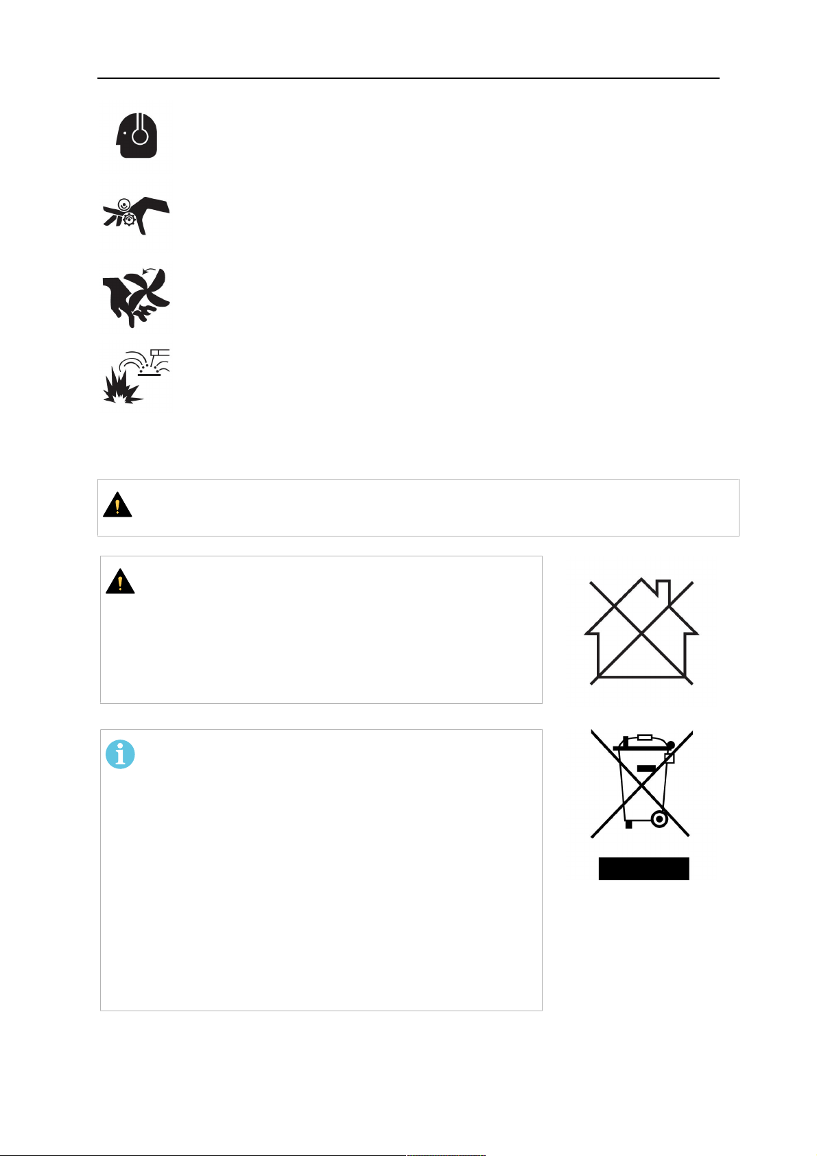
NOISE - Excessive noise can damage hearing
Protect your ears. Use earmuffs or other hearing protection.
MOVING PARTS - Can cause injuries
• Keep all doors, panels and covers closed and securely in place. Have only
qualified people remove covers for maintenance and troubleshooting as
necessary. Reinstall panels or covers and close doors when service is
finished and before starting engine.
• Stop engine before installing or connecting unit.
• Keep hands, hair, loose clothing and tools away from moving parts.
FIRE HAZARD
• Sparks (spatter) can cause fire. Make sure therefore that there are no
inflammable materials nearby
• Do not use on closed containers.
MALFUNCTION - Call for expert assistance in the event of malfunction.
PROTECT YOURSELF AND OTHERS!
CAUTION!
This product is solely intended for arc welding.
CAUTION!
Class A equipment is not intended for use in residential
locations where the electrical power is provided by the
public low-voltage supply system. There may be
potential difficulties in ensuring electromagnetic
compatibility of class A equipment in those locations,
due to conducted as well as radiated disturbances.
NOTE!
Dispose of electronic equipment at the recycling
facility!
In observance of European Directive 2012/19/EC on
Waste Electrical and Electronic Equipment and its
implementation in accordance with national law,
electrical and/or electronic equipment that has reached
the end of its life must be disposed of at a recycling
facility.
As the person responsible for the equipment, it is your
responsibility to obtain information on approved
collection stations.
For further information contact the nearest ESAB dealer.
ESAB has an assortment of welding accessories and personal protection equipment
for purchase. For ordering information contact your local ESAB dealer or visit us on
our website.
0444 408 301
- 7 -
© ESAB AB 2021
2 INTRODUCTION
2 INTRODUCTION
The wire feed unit Feed 3004 with control panel U6, MA23, MA24 or MA25 Pulse is
intended for MIG/MAG welding together with 400A, 500A and 600A CAN welding power
sources.
The wire feed unit Feed 4804 with control panel U6, MA23 or MA24 is intended for
MIG/MAG welding together with 400A, 500A and 600A CAN welding power sources.
The wire feed units contain four-wheel drive wire feed mechanisms as well as control
electronics.
They can be used together with wire on ESAB's MarathonPac™, or on wire bobbin (standard
Ø 300 mm, accessory Ø 440 mm).
The wire feed unit can be installed either on the power source trolley, suspended above the
workplace, on a counter balance device or on the floor with or without wheel set.
ESAB's accessories for the product can be found in chapter "ACCESSORIES" of this
manual.
2.1 Equipment
The wire feed unit is supplied with:
• instruction manual for the wire feed unit
• instruction manual in English for the control panel
Instruction manuals in other languages can be downloaded from the Internet:
www.esab.com
• decal with recommended wear parts.
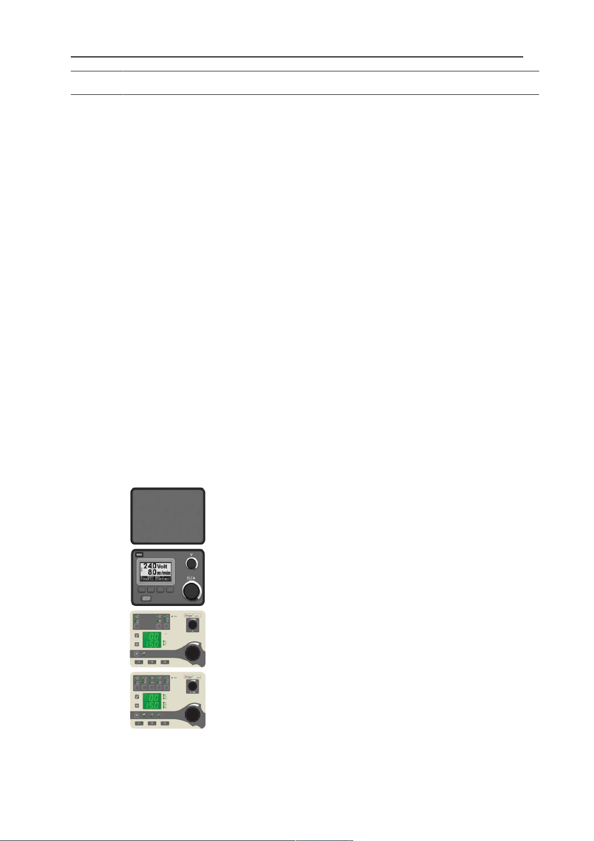
2.2 Control panel
The wire feed unit is supplied with one of the following control panels:
Empty panel for use with double wire feed units or
with use of control box U82.
Knobs for setting the voltage and the wire feed speed
U6
MA23
/ current. Other parameters are controlled by
pushbuttons, with text in the display panel.
Knobs for setting the voltage and the wire feed speed
/ current. Other settings with push buttons.
MA24
0444 408 301
Knobs for setting the voltage / QSet™ and the wire
feed speed / current. Other settings with push
buttons.
- 8 -
© ESAB AB 2021

2 INTRODUCTION
Knobs for setting the voltage / QSet™ and the wire
feed speed / current. Other settings with push
buttons.
MA25
Pulse
See the separate instruction manual for a detailed description of the control panels.
0444 408 301
- 9 -
© ESAB AB 2021

3 TECHNICAL DATA
3 TECHNICAL DATA
Feed 3004 Feed 4804
Mains voltage 42 V 50-60 Hz 42 V 50-60 Hz
Power requirement 336 VA 378 VA
Motor current I
max
5 A 9 A
Wire feed speed 0.8 - 25.0 m/min 0.8 - 25.0 m/min
Torch connection EURO EURO
Max. diameter wire bobbin 300 mm (*440 mm) 300 mm (*440 mm)
Wire dimension
Fe 0.8 - 1.6 mm 0.8 - 2.4 mm
Ss 0.8 - 1.6 mm 0.8 - 2.4 mm
Al 1.0 & 1.6 mm 1.0 & 2.4 mm
Cored wire 0.9 - 1.6 mm 0.9 - 2.4 mm
Weight 15 kg 19 kg
Dimensions (l x w x h) 690 x 275 x 420 mm 690 x 275 x 420 mm
Operating temperature -10 to +40°C -10 to +40°C
Shielding gas All types intended for
MIG/MAG welding
All types intended for
MIG/MAG welding
max pressure 0.5 MPa ( 5 bar) 0.5 MPa ( 5 bar)
Coolant ESAB's ready mixed coolant ESAB's ready mixed coolant
max pressure 0.5 MPa ( 5 bar) 0.5 MPa ( 5 bar)
Maximum permissible load at
60% duty cycle 630 A 630 A
100% duty cycle 500 A 500 A
Enclosure class IP23 IP23
*Accessories can be found in the "ACCESSORIES" chapter.
Duty cycle
The duty cycle refers to the time as a percentage of a ten-minute period that you can weld or
cut at a certain load without overloading. The duty cycle is valid for 40°C/104°F, or below.
Enclosure class
The IP code indicates the enclosure class, i.e. the degree of protection against penetration
by solid objects or water.
Equipment marked IP23 is intended for indoor and outdoor use.
0444 408 301
- 10 -
© ESAB AB 2021
4 INSTALLATION
4 INSTALLATION
The installation must be carried out by a professional.
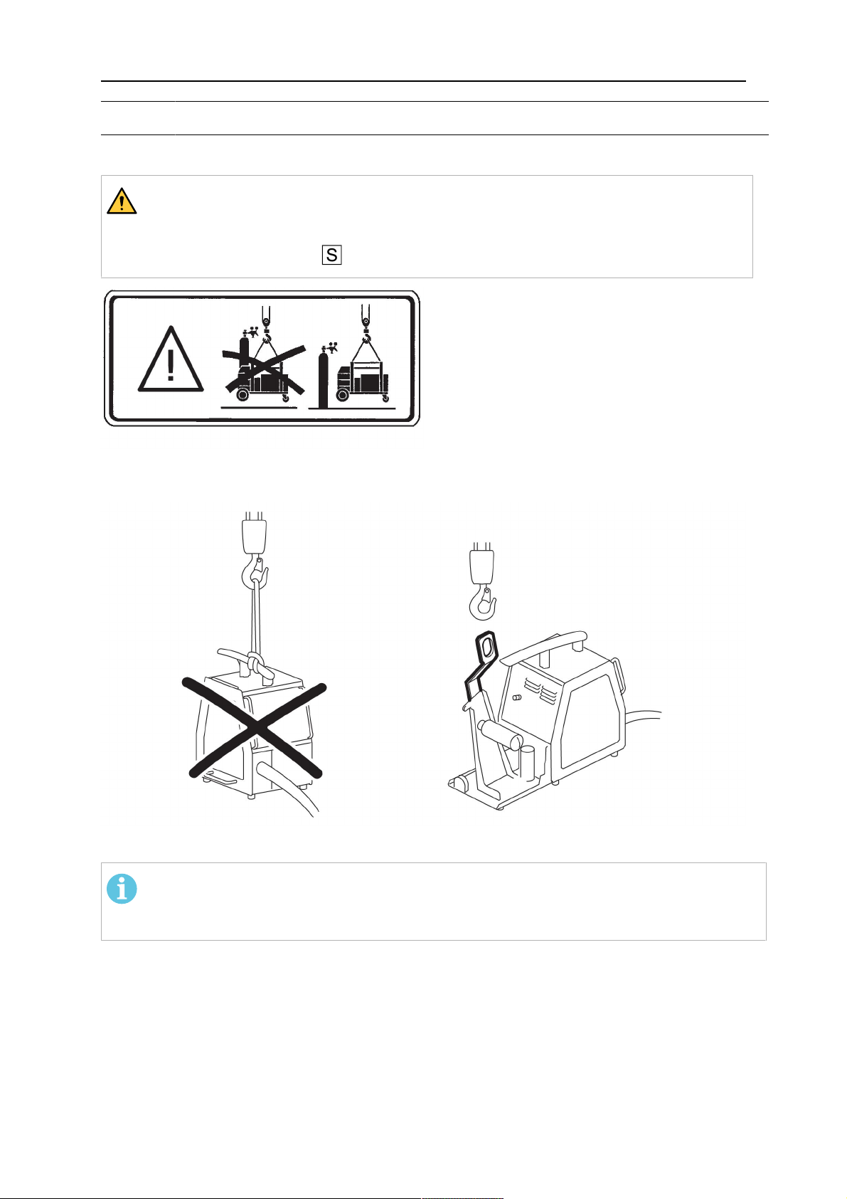
WARNING!
When welding in an environment with increased electrical danger, only power
sources intended for this environment may be used. These power sources are
marked with the symbol .
4.1 Lifting instructions
Order number for lifting eyelet can be found in chapter "ACCESSORIES".
NOTE!
If another mounting device is used, this must be electrically insulated from the wire
feed unit.
0444 408 301
- 11 -
© ESAB AB 2021
 Loading...