


Installation, Operation and Maintenance for the
®
EtchArc
-1125
PLASMA MARKING SYSTEM
F15-727
May, 2005
411 South Ebenezer Road
Florence, SC 29501-0545

The equipment described in this manual is
potentially hazardous. Use caution when installing,
operating and maintaining this equipment.
Purchaser is solely responsible for the safe
operation and use of all products purchased,
including compliance with OSHA and other
government standards. ESAB Cutting
Systems has no liability for personal injury or
other damage arising out of the use of any
product manufactured or sold be ESAB. See
standard ESAB terms and conditions of sale
for a specific statement of ESAB’s
responsibilities and limitations on its liability.
ESAB Cutting Systems first priority is total
customer satisfaction. We constantly look for
ways to improve our products, service and
documentation. As a result, we make
enhancements and/or design changes as
required. ESAB makes every possible effort to
ensure our documentation is current. We
cannot guarantee that each piece of
documentation received by our customers
reflects the latest design enhancements.
Therefore, the information contained in this
document is subject to change without notice.
This manual is ESAB Part Number F15727
This manual is ESAB Part Number F15727
This manual is ESAB Part Number F15727This manual is ESAB Part Number F15727
....
This manual is for the convenience and use of the
cutting machine purchaser. It is not a contract or
other obligation on the part of ESAB Cutting
Systems.
Printed in U.S.A.
©
© ESAB Cutting Systems, 2005
©©

EtchArc-1125 Table of Contents
Page
Section 1 Safety
1.1 Introduction.................................................................................................... 1
1.2 Safety Notations And Symbols........................................................................ 1
1.3 General Safety Information.............................................................................. 2
1.4 Installation Precautions................................................................................... 3
1.5 Electrical Grounding ....................................................................................... 4
1.6 Operating A Plasma Cutting Machine.............................................................. 4-7
1.7 Service Precautions........................................................................................ 8
1.8 Safety References .......................................................................................... 9
1.8.1 National Standards................................................................................. 9
1.8.2 International Standards........................................................................... 10-11
Section 2 Description
2.1 Introduction Overview...................................................................................... 1
2.1.1 Interconnection Diagram......................................................................... 2
2.2 System Description ........................................................................................ 3
2.2.1 EtchArc-1125 Systems........................................................................... 3
2.2.2 EtchArc-1125 Power Supply (only).......................................................... 3
2.2.3 PM60 Plasma Marker Torch.................................................................... 4
2.2.4 PM60 Torch Lead Assemblies ................................................................ 4
2.2.5 Options .................................................................................................. 4
Section 3 Installation
3.0 General .......................................................................................................... 1
3.1 Interface......................................................................................................... 2
3.2 Requirements................................................................................................. 3
3.3 Connecting the EtchArc.................................................................................. 4
3.3.1 Rear Panel.............................................................................................. 4
3.3.2 Converting a 230 VAC unit to a 208 VAC unit.......................................... 5
3.3.3 Torch Lead Connections, Front Panel ..................................................... 6-7
3.3.4 Torch Bundle (Leads) to PM60 Torch...................................................... 8-13
i

EtchArc-1125 Table of Contents
Page
Section 4 Operation
4.0 Set-up ............................................................................................................ 1
4.1 Power Supply ................................................................................................. 1
4.2 Gas Set-up..................................................................................................... 2
4.3 CNC Set-up.................................................................................................... 3
4.4 Process Data................................................................................................... 4-10
Section 5 Maintenance
5.0 General........................................................................................................... 1
5.1 Routine Maintenance ...................................................................................... 2
5.2 Flow Switch .................................................................................................... 3
Section 6 Troubleshooting
6.0 General........................................................................................................... 1
6.1 Troubleshooting Guide.................................................................................... 1-5
6.2 Power Supply Schematic, 208/230v (P/N 0588000967)................................. 6-7
6.3 Wiring Diagram, 208/230v............................................................................... 8-11
6.4 Power Supply Schematic, 460v (P/N 0588000949)........................................ 12-13
6.5 Wiring Diagram, 460v...................................................................................... 14-17
6.6 Power Supply Schematic, 575v (P/N 0588000966)........................................ 18-19
6.7 Wiring Diagram, 575v...................................................................................... 20-23
6.8 Plasma (CUT) Gas Circuit................................................................................ 24
ii

EtchArc-1125 Table of Contents
Page
Section 7 Replacement Parts
7.1 General .......................................................................................................... 1
7.2 Ordering......................................................................................................... 1
7.3 EtchArc-1125, Front and Rear Exterior, all models .......................................... 2-3
7.4 EtchArc-1125, Right interior view, 208/230V model......................................... 4-5
7.5 EtchArc-1125, Left interior view, 208/230v model ........................................... 6-7
7.6 EtchArc-1125, Top interior view with cover removed, 208/230v model ............ 8-9
7.7 EtchArc-1125, Top interior cross section view 1, 208/230v model................... 10-11
7.8 EtchArc-1125, Top interior cross section view 2, 208/230v model................... 12-13
7.9 EtchArc-1125, Right interior view, 460v and 575v models............................... 14-15
7.10 EtchArc-1125, Left interior view, 460v and 575v models ............................... 16-17
7.11 EtchArc-1125, Top interior view with cover removed, 460v and 575v models 18-19
7.12 EtchArc-1125, Top interior cross section view 1, 460v and 575v models....... 20-21
7.13 EtchArc-1125, Top interior cross section view 2, 460v and 575v models....... 22-23
7.14 TechArc-1125 Inside View, 460v and 575v models ....................................... 24-25
7.15 Argon Gas Circuit (Cut Gas).......................................................................... 26-27
7.16 PM60 Plasma Torch..................................................................................... 28-29
7.17 Torch Leads and Other System Parts............................................................ 30-31
7.18 PM-60 Plasma Marking Torch Starter Spare Parts Kit.................................... 32-33
Back Manual
Customer/Technical Information
Cover
iii

EtchArc-1125 Table of Contents
This page intentionally left blank
iv

SECTION 1 Safety
1.1 Introduction
The process of cutting metals with plasma equipment
1.2 Safety Notations And Symbols
!
DANGER
!
provides industry with a valuable and versatile tool.
ESAB cutting machines are designed to provide both
operation safety and efficiency. However, as with any
machine tool, sensible attention to operating
procedures, precautions, and safe practices is
necessary to achieve a full measure of usefulness.
Whether an individual is involved with operation,
servicing, or as an observer, compliance with
established precautions and safe practices must be
accomplished. Failure to observe certain precautions
could result in serious personnel injury or severe
equipment damage. The following precautions are
general guidelines applicable when working with
cutting machines. More explicit precautions pertaining
to the basic machine and accessories are found in the
instruction literature. For a wide scope of safety
information on the field of cutting and welding
apparatus, obtain and read the publications listed in
the Recommended References.
The following words and symbols are used throughout
this manual. They indicate different levels of required
safety involvement.
ALERT or ATTENTION. Your safety is involved
or potential equipment failure exists. Used with
other symbols and information.
Used to call attention to immediate hazards
which, if not avoided, will result in serious
personal injury or loss of life.
WARNING
!
CAUTION
!
CAUTION
NOTICE
EtchArc-1125 Power Source 1-1
Used to call attention to potential hazards that
could result in personal injury or loss of life.
Used to call attention to hazards that could result
in minor personal injury or equipment damage.
Used to call attention to minor hazards to
equipment.
Used to call attention to important installation,
operation or maintenance information not
directly related to safety hazards.

SECTION 1 Safety
1.3 General Safety Information
WARNING
!
Machinery often starts automatically.
This equipment moves in various directions and
This equipment moves in various directions and
This equipment moves in various directions and This equipment moves in various directions and
speeds.
speeds.
speeds.speeds.
• Moving machinery can crush.
Moving machinery can crush.
Moving machinery can crush.Moving machinery can crush.
• Only qualified personnel should operate or
Only qualified personnel should operate or
Only qualified personnel should operate or Only qualified personnel should operate or
service this power source.
service this power source.
service this power source.service this power source.
• Keep all personnel, materials, and equipment
Keep all personnel, materials, and equipment
Keep all personnel, materials, and equipment Keep all personnel, materials, and equipment
not involved in prod
not involved in production process clear of
not involved in prodnot involved in prod
entire system area.
entire system area.
entire system area.entire system area.
• Fence off entire work cell to prevent personnel
Fence off entire work cell to prevent personnel
Fence off entire work cell to prevent personnel Fence off entire work cell to prevent personnel
from passing through area or standing in the
from passing through area or standing in the
from passing through area or standing in the from passing through area or standing in the
working envelope of the equipment.
working envelope of the equipment.
working envelope of the equipment. working envelope of the equipment.
• Post appropriate WARNING signs at every work
Post appropriate WARNING signs at every work
Post appropriate WARNING signs at every work Post appropriate WARNING signs at every work
cell entrance.
cell entrance.
cell entrance. cell entrance.
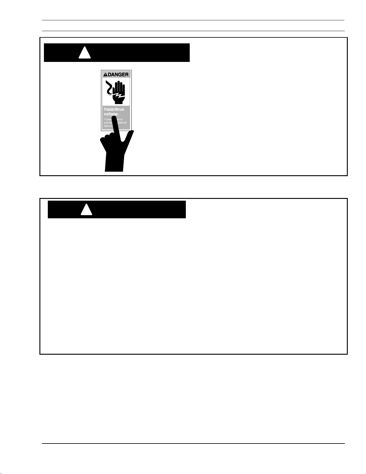
• Follow lockout proced
Follow lockout procedure before servicing any
Follow lockout procedFollow lockout proced
equipment.
equipment.
equipment.equipment.
uction process clear of
uction process clear of uction process clear of
ure before servicing any
ure before servicing any ure before servicing any
Failure to follow operating instructions
WARNING
!
could result in death or serious injury.
Read and understand this operator’s manual before
Read and understand this operator’s manual before
Read and understand this operator’s manual before Read and understand this operator’s manual before
using machine.
using machine.
using machine.using machine.
• Read entire procedure before operating or
Read entire procedure before operating or
Read entire procedure before operating or Read entire procedure before operating or
performing any system maintenance.
performing any system maintenance.
performing any system maintenance. performing any system maintenance.
• Special attention must be given to all hazard
Special attention must be given to all hazard
Special attention must be given to all hazard Special attention must be given to all hazard
warnings that provide essential information
warnings that provide essential information
warnings that provide essential information warnings that provide essential information
re
regarding personnel safety and/or possible
garding personnel safety and/or possible
rere
garding personnel safety and/or possible garding personnel safety and/or possible
equipment damage.
equipment damage.
equipment damage.equipment damage.
• All safety precautions relevant to electrical
All safety precautions relevant to electrical
All safety precautions relevant to electrical All safety precautions relevant to electrical
equipment and process operations must be
equipment and process operations must be
equipment and process operations must be equipment and process operations must be
strictly observed by all having system
strictly observed by all having system
strictly observed by all having system strictly observed by all having system
responsibility or access.
responsibility or access.
responsibility or access. responsibility or access.
• Read all safety publications made available
Read all safety publications made available by
Read all safety publications made availableRead all safety publications made available
your company.
your company.
your company.your company.
by
by by
EtchArc-1125 Power Source 1-2
SECTION 1 Safety
Failure to follow safety warning label
WARNING
!
1.4 Installation Precautions
instructions could result in death or
serious injury.
Read and understand all safety warning labels on
Read and understand all safety warning labels on
Read and understand all safety warning labels on Read and understand all safety warning labels on
machine.
machine.
machine.machine.
Refer to operator’s manual for additiona
Refer to operator’s manual for additional safety
Refer to operator’s manual for additionaRefer to operator’s manual for additiona
information.
information.
information.information.
l safety
l safety l safety
WARNING
!
Improperly Installed Equipment Can Cause
Injury Or Death.
Follow these guidelines while installing machine:
Follow these guidelines while installing machine:
Follow these guidelines while installing machine:Follow these guidelines while installing machine:
• Contact your ESAB representative before
Contact your ESAB representative before
Contact your ESAB representative before Contact your ESAB representative before
installation. He can suggest certain precautio
installation. He can suggest certain precautions
installation. He can suggest certain precautioinstallation. He can suggest certain precautio
regarding piping installation and machine lifting,
regarding piping installation and machine lifting,
regarding piping installation and machine lifting, regarding piping installation and machine lifting,
etc. to ensure maximum security.
etc. to ensure maximum security.
etc. to ensure maximum security.etc. to ensure maximum security.
• Never attempt any machine modifications or
Never attempt any machine modifications or
Never attempt any machine modifications or Never attempt any machine modifications or
apparatus additions without first consulting a
apparatus additions without first consulting a
apparatus additions without first consulting a apparatus additions without first consulting a
qualified ESAB representative.
qualified ESAB representative.
qualified ESAB representative.qualified ESAB representative.
• Observe machine clearance requirements for
Observe machine clearance requirements for
Observe machine clearance requirements for Observe machine clearance requirements for
prope
proper operation and personnel safety.
r operation and personnel safety.
propeprope
r operation and personnel safety. r operation and personnel safety.
• Always have qualified personnel perform
Always have qualified personnel perform
Always have qualified personnel perform Always have qualified personnel perform
installation, troubleshooting and maintenance of
installation, troubleshooting and maintenance of
installation, troubleshooting and maintenance of installation, troubleshooting and maintenance of
this equipment.
this equipment.
this equipment.this equipment.
• Provide a wall mounted disconnect switch with
Provide a wall mounted disconnect switch with
Provide a wall mounted disconnect switch with Provide a wall mounted disconnect switch with
proper fuse sizes close to the power supply.
proper fuse sizes close to the power supply.
proper fuse sizes close to the power supply.proper fuse sizes close to the power supply.
ns
ns ns
EtchArc-1125 Power Source 1-3
SECTION 1 Safety
1.5 Electrical Grounding
Electrical grounding is imperative for proper
machine operation and SAFETY. Refer to this
manual’s Installation section for detailed grounding
instructions.
Electric shock hazard.
WARNING
!
1.6 Operating A Plasma Cutting Machine
Improper grounding can cause severe injury or
Improper grounding can cause severe injury or
Improper grounding can cause severe injury or Improper grounding can cause severe injury or
death.
death.
death.death.
Machine
Machine must be properly grounded before put into
MachineMachine
service.
service.
service.service.
must be properly grounded before put into
must be properly grounded before put into must be properly grounded before put into
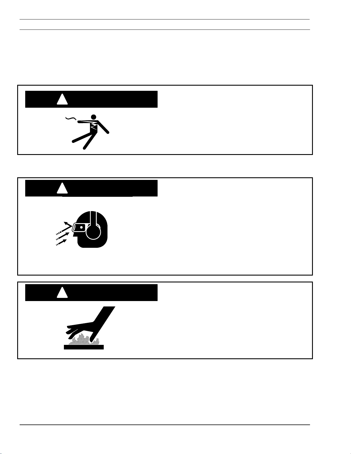
Flying debris and loud noise
WARNING
!
hazards.
• Hot spatter can burn and injure eyes. Wear
Hot spatter can burn and injure eyes. Wear
Hot spatter can burn and injure eyes. Wear Hot spatter can burn and injure eyes. Wear
goggles to protect eyes from burns and flying
goggles to protect eyes from burns and flying
goggles to protect eyes from burns and flying goggles to protect eyes from burns and flying
debris generated during
debris generated during operation.
debris generated during debris generated during
operation.
operation.operation.
• Chipped slag may be hot and fly far.
Chipped slag may be hot and fly far.
Chipped slag may be hot and fly far. Chipped slag may be hot and fly far.
Bystanders should also wear goggles and
Bystanders should also wear goggles and
Bystanders should also wear goggles and Bystanders should also wear goggles and
safety glasses.
safety glasses.
safety glasses.safety glasses.
• Noise from plasma arc can damage hearing.
Noise from plasma arc can damage hearing.
Noise from plasma arc can damage hearing. Noise from plasma arc can damage hearing.
Wear correct ear protection when cutting above
Wear correct ear protection when cutting above
Wear correct ear protection when cutting above Wear correct ear protection when cutting above
water.
water.
water. water.
Burn hazard.
WARNING
!
Hot metal can burn.
Hot metal can burn.
Hot metal can burn.Hot metal can burn.
• Do not touch m
Do not touch metal plate or parts immediately
Do not touch mDo not touch m
after cutting. Allow metal time to cool, or douse
after cutting. Allow metal time to cool, or douse
after cutting. Allow metal time to cool, or douse after cutting. Allow metal time to cool, or douse
with water.
with water.
with water.with water.
• Do not touch plasma torch immediately after
Do not touch plasma torch immediately after
Do not touch plasma torch immediately after Do not touch plasma torch immediately after
cutting. Allow torch time to cool.
cutting. Allow torch time to cool.
cutting. Allow torch time to cool.cutting. Allow torch time to cool.
etal plate or parts immediately
etal plate or parts immediately etal plate or parts immediately
EtchArc-1125 Power Source 1-4

SECTION 1 Safety
g
!
can kill.
• Do NOT touch plasma torch, cutti
Do NOT touch plasma torch, cutting table or
Do NOT touch plasma torch, cuttiDo NOT touch plasma torch, cutti
cable connections during plasma cutting process.
cable connections during plasma cutting process.
cable connections during plasma cutting process.cable connections during plasma cutting process.
• Always turn power off to plasma power
Always turn power off to plasma power
Always turn power off to plasma power Always turn power off to plasma power
supplies before touching or servicing plasma torch.
supplies before touching or servicing plasma torch.
supplies before touchin
• Always turn power off to plasma power
Always turn power off to plasma power
Always turn power off to plasma power Always turn power off to plasma power
supplies before servicing any system component.
supplies before servicing any system component.
supplies before servicing any system component.supplies before servicing any system component.
• Do not touch live
Do not touch live electrical parts.
Do not touch liveDo not touch live
• Keep all panels and covers in place when
Keep all panels and covers in place when
Keep all panels and covers in place when Keep all panels and covers in place when
machine is connected to power source.
machine is connected to power source.
machine is connected to power source.machine is connected to power source.
• Wear insulating gloves, shoes and clothing to
Wear insulating gloves, shoes and clothing to
Wear insulating gloves, shoes and clothing to Wear insulating gloves, shoes and clothing to
insulate yourself from workpiece and electrical
insulate yourself from workpiece and electrical
insulate yourself from workpiece and electrical insulate yourself from workpiece and electrical
ground.
ground.
ground.ground.
• Keep gloves, shoes, clothing, work area, and
Keep gloves, shoes, clothing, work area, and
Keep gloves, shoes, clothing, work area, and Keep gloves, shoes, clothing, work area, and
equipment d
equipment dry.
equipment dequipment d
• Replace worn or damaged cables.
Replace worn or damaged cables.
Replace worn or damaged cables.Replace worn or damaged cables.
ry.
ry.ry.
or servicing plasma torch. supplies before touching or servicing plasma torch.
electrical parts.
electrical parts. electrical parts.
ng table or
ng table or ng table or
WARNING
Hazardous voltages. Electric shock
WARNING
!
Fume hazard.
Fumes and gases generated by the plasma cutting
Fumes and gases generated by the plasma cutting
Fumes and gases generated by the plasma cutting Fumes and gases generated by the plasma cutting
process can be hazardous to your health.
process can be hazardous to your health.
process can be hazardous to your health.process can be hazardous to your health.
• Do NOT breathe fumes.
Do NOT breathe fumes.
Do NOT breathe fumes.Do NOT breathe fumes.
• Do not operate plasma torch without fume
Do not operate plasma torch without fume
Do not operate plasma torch without fume Do not operate plasma torch without fume
removal system operating properly.
removal system operating properly.
removal system operating properly. removal system operating properly.
• Use additional
Use additional ventilation to remove fumes if
Use additionalUse additional
necessary.
necessary.
necessary.necessary.
• Use approved respirator if ventilation is not
Use approved respirator if ventilation is not
Use approved respirator if ventilation is not Use approved respirator if ventilation is not
adequate.
adequate.
adequate.adequate.
• Provide positive mechanical ventilation when
Provide positive mechanical ventilation when
Provide positive mechanical ventilation when Provide positive mechanical ventilation when
cutting galvanized steel, stainless steel, copper,
cutting galvanized steel, stainless steel, copper,
cutting galvanized steel, stainless steel, copper, cutting galvanized steel, stainless steel, copper,
zinc, beryllium, or cadmium. Do not breathe these
zinc, beryllium, or cadmium. Do not breathe these
zinc, beryllium, or cadmium. Do not breathe these zinc, beryllium, or cadmium. Do not breathe these
fumes.
fumes.
fumes.fumes.
Do
Do not operate near degreasing and spraying
•
Do Do
operations. Heat or arc rays can react with
operations. Heat or arc rays can react with
operations. Heat or arc rays can react with operations. Heat or arc rays can react with
chlorinated hydrocarbon vapors to form phosgene,
chlorinated hydrocarbon vapors to form phosgene,
chlorinated hydrocarbon vapors to form phosgene, chlorinated hydrocarbon vapors to form phosgene,
a highly toxic gas and other irritant gases.
a highly toxic gas and other irritant gases.
a highly toxic gas and other irritant gases. a highly toxic gas and other irritant gases.
not operate near degreasing and spraying
not operate near degreasing and spraying not operate near degreasing and spraying
ventilation to remove fumes if
ventilation to remove fumes if ventilation to remove fumes if
EtchArc-1125 Power Source 1-5

SECTION 1 Safety
WARNING
!
Radiation hazard.
Arc rays can injure eyes and burn skin.
Arc rays can injure eyes and burn skin.
Arc rays can injure eyes and burn skin.Arc rays can injure eyes and burn skin.
• Wear corre
Wear correct eye and body protection.
Wear correWear corre
• Wear dark safety glasses or goggles with side
Wear dark safety glasses or goggles with side
Wear dark safety glasses or goggles with side Wear dark safety glasses or goggles with side
shields. Refer to following chart for recommended
shields. Refer to following chart for recommended
shields. Refer to following chart for recommended shields. Refer to following chart for recommended
lens shades for plasma cutting:
lens shades for plasma cutting:
lens shades for plasma cutting:lens shades for plasma cutting:
Arc Current
Up to 100 Amps
100
200
Over 400 Amps
• Replace glasses/goggles when lenses are
pitted or broken
pitted or broken
pitted or brokenpitted or broken
• Warn others in area not to look directly at the
arc unless wearing appropriate safety glasses.
arc unless wearing appropriate safety glasses.
arc unless wearing appropriate safety glasses.arc unless wearing appropriate safety glasses.
• Prepare cutting area to reduce reflection and
transmission
transmission of ultraviolet light.
transmissiontransmission
Arc Current Lens Shade
Arc CurrentArc Current
Up to 100 Amps Shade No. 8
Up to 100 AmpsUp to 100 Amps
100----200 Amps
100100
200----400
200200
Over 400 Amps Shade No. 14
Over 400 AmpsOver 400 Amps
Replace glasses/goggles when lenses are
Replace glasses/goggles when lenses are Replace glasses/goggles when lenses are
Warn others in area not to look directly at the
Warn others in area not to look directly at the Warn others in area not to look directly at the
Prepare cutting area to reduce reflection and
Prepare cutting area to reduce reflection and Prepare cutting area to reduce reflection and
§ Use special paint on walls to absorb UV
light.
light.
light.light.
ct eye and body protection.
ct eye and body protection.ct eye and body protection.
Lens Shade
Lens Shade Lens Shade
Shade No. 8
Shade No. 8Shade No. 8
200 Amps Shade No. 10
200 Amps200 Amps
400 Amps
400 400
of ultraviolet light.
of ultraviolet light. of ultraviolet light.
Use special paint on walls to absorb UV
Use special paint on walls to absorb UV Use special paint on walls to absorb UV
Shade No. 10
Shade No. 10Shade No. 10
Amps Shade No. 12
Shade No. 12
AmpsAmps
Shade No. 12Shade No. 12
Shade No. 14
Shade No. 14Shade No. 14
§ Install protective screens or curtains to
Install protective screens or curtains to
Install protective screens or curtains to Install protective screens or curtains to
reduce ultraviolet transmission.
reduce ultraviolet transmission.
reduce ultraviolet transmission.reduce ultraviolet transmission.
EtchArc-1125 Power Source 1-6
SECTION 1 Safety
!
WARNING
!
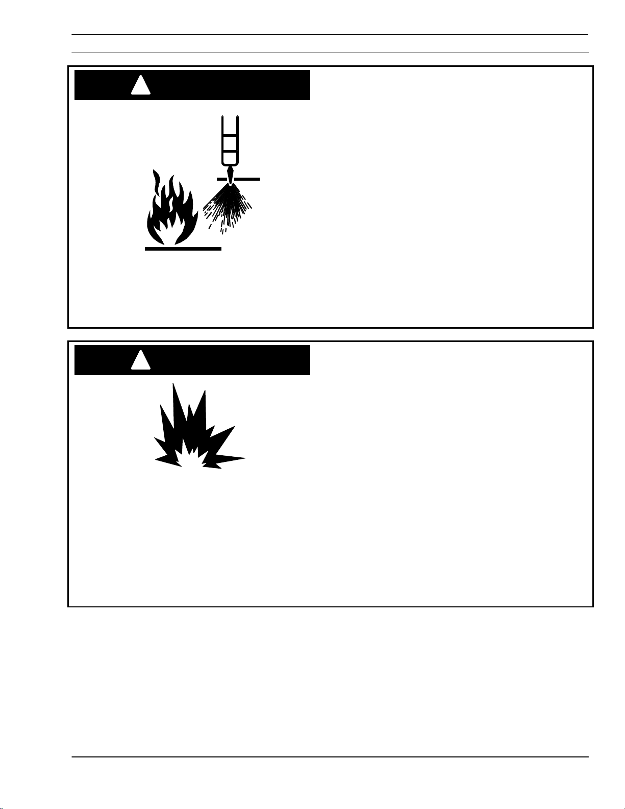
Heat, spatter, and sparks cause fire and burns.
Heat, spatter, and sparks cause fire and burns.
Heat, spatter, and sparks cause fire and burns. Heat, spatter, and sparks cause fire and burns.
• Do not cut near combustible material.
Do not cut near combustible material.
Do not cut near combustible material.Do not cut near combustible material.
• Do
Do not have on your person any combustibles
not have on your person any combustibles
DoDo
not have on your person any combustibles not have on your person any combustibles
(e.g. butane lighter).
(e.g. butane lighter).
(e.g. butane lighter).(e.g. butane lighter).
• Pilot arc can cause burns. Keep torch nozzle
Pilot arc can cause burns. Keep torch nozzle
Pilot arc can cause burns. Keep torch nozzle Pilot arc can cause burns. Keep torch nozzle
away from yourself and others when activating
away from yourself and others when activating
away from yourself and others when activating away from yourself and others when activating
plasma process.
plasma process.
plasma process.plasma process.
• Wear correct eye and body protection.
Wear correct eye and body protection.
Wear correct eye and body protection.Wear correct eye and body protection.
• Wear gauntlet gloves, safety shoes and hat.
Wear gauntlet gloves, safety shoes and hat.
Wear gauntlet gloves, safety shoes and hat.Wear gauntlet gloves, safety shoes and hat.
• WWWWear flame
ear flame----retardant clothing covering all
ear flameear flame
exposed areas.
exposed areas.
exposed areas.exposed areas.
• Wear cuffless trousers to prevent entry of
Wear cuffless trousers to prevent entry of
Wear cuffless trousers to prevent entry of Wear cuffless trousers to prevent entry of
sparks and slag.
sparks and slag.
sparks and slag.sparks and slag.
• Have fire extinguishing equipment available for
Have fire extinguishing equipment available for
Have fire extinguishing equipment available for Have fire extinguishing equipment available for
use.
use.
use.use.
retardant clothing covering all
retardant clothing covering all retardant clothing covering all
Explosion hazard.
• Certain molten aluminum
Certain molten aluminum----lithium (Al
Certain molten aluminumCertain molten aluminum
can cause explos
can cause explosions when plasma cut OVER
can cause exploscan cause explos
water.
water.
water. water.
§ These alloys should only be dry cut on a
These alloys should only be dry cut on a
These alloys should only be dry cut on a These alloys should only be dry cut on a
dry table.
dry table.
dry table.dry table.
§ DO NOT dry cut over water.
DO NOT dry cut over water.
DO NOT dry cut over water.DO NOT dry cut over water.
ions when plasma cut OVER
ions when plasma cut OVER ions when plasma cut OVER
lithium (Al----Li) alloys
lithium (Allithium (Al
Li) alloys
Li) alloys Li) alloys
WARNING
Burn Hazard.
§ Contact your aluminum supplier for
Contact your aluminum supplier for
Contact your aluminum supplier for Contact your aluminum supplier for
additional safety information regarding
additional safety information regarding
additional safety information regarding additional safety information regarding
hazards associated with these alloys
hazards associated with these alloys
hazards associated with these alloyshazards associated with these alloys
Do not cut in atmospheres con
Do not cut in atmospheres containing
•
Do not cut in atmospheres conDo not cut in atmospheres con
explosive dust or vapors.
explosive dust or vapors.
explosive dust or vapors.explosive dust or vapors.
•
Do not carry any combustibles on your person
Do not carry any combustibles on your person
Do not carry any combustibles on your person Do not carry any combustibles on your person
(e.g. butane lighter)
(e.g. butane lighter)
(e.g. butane lighter)(e.g. butane lighter)
• Do not cut containers that have held
Do not cut containers that have held
Do not cut containers that have held Do not cut containers that have held
combustibles.
combustibles.
combustibles.combustibles.
EtchArc-1125 Power Source 1-7
taining
taining taining
.

SECTION 1 Safety
g
1.7 Service Precautions
!
CAUTION
CAUTION
!
can kill.
• Do NOT touch plasma torch
Do NOT touch plasma torch, cutting table or
Do NOT touch plasma torchDo NOT touch plasma torch
cable connections during plasma cutting process.
cable connections during plasma cutting process.
cable connections during plasma cutting process.cable connections during plasma cutting process.
• Always turn power off to plasma power
Always turn power off to plasma power
Always turn power off to plasma power Always turn power off to plasma power
supplies before touching or servicing plasma torch.
supplies before touching or servicing plasma torch.
supplies before touchin
• Always turn power off to plasma power
Always turn power off to plasma power
Always turn power off to plasma power Always turn power off to plasma power
supplies before removing covers or panels to
supplies before removing covers or panels to
supplies before removing covers or panels to supplies before removing covers or panels to
service any s
service any system component.
service any sservice any s
• Do not touch live electrical parts.
Do not touch live electrical parts.
Do not touch live electrical parts.Do not touch live electrical parts.
• Keep all panels and covers in place when
Keep all panels and covers in place when
Keep all panels and covers in place when Keep all panels and covers in place when
machine is connected to power source.
machine is connected to power source.
machine is connected to power source.machine is connected to power source.
• Keep gloves, shoes, clothing, work area, and
Keep gloves, shoes, clothing, work area, and
Keep gloves, shoes, clothing, work area, and Keep gloves, shoes, clothing, work area, and
equipment dry.
equipment dry.
equipment dry.equipment dry.
• Inspect power and ground leads cables for
Inspect power and ground leads cables for
Inspect power and ground leads cables for Inspect power and ground leads cables for
wear or cracking. Repl
wear or cracking. Replace worn or damaged
wear or cracking. Replwear or cracking. Repl
cables. Do not use if damaged.
cables. Do not use if damaged.
cables. Do not use if damaged.cables. Do not use if damaged.
• Never bypass safety interlocks.
Never bypass safety interlocks.
Never bypass safety interlocks.Never bypass safety interlocks.
• Follow lock
Follow lock----out procedures.
Follow lockFollow lock
Establish and adhere to preventive maintenance.
Establish and adhere to preventive maintenance.
Establish and adhere to preventive maintenance. Establish and adhere to preventive maintenance.
A composite program can be established from
A composite program can be established from
A composite program can be established from A composite program can be established from
recommended schedules.
recommended schedules.
recommended schedules.recommended schedules.
Avoid leaving test equ
Avoid leaving test equipment or hand tools on
Avoid leaving test equAvoid leaving test equ
machine. Severe electrical or mechanical damage
machine. Severe electrical or mechanical damage
machine. Severe electrical or mechanical damage machine. Severe electrical or mechanical damage
could occur to equipment or machine.
could occur to equipment or machine.
could occur to equipment or machine.could occur to equipment or machine.
Extreme caution should be used when probing
Extreme caution should be used when probing
Extreme caution should be used when probing Extreme caution should be used when probing
circuitry with an oscilloscope or voltmeter.
circuitry with an oscilloscope or voltmeter.
circuitry with an oscilloscope or voltmeter. circuitry with an oscilloscope or voltmeter.
Integrated circuits are susceptible to over volta
Integrated circuits are susceptible to over voltage
Integrated circuits are susceptible to over voltaIntegrated circuits are susceptible to over volta
damage. Power off before using test probes to
damage. Power off before using test probes to
damage. Power off before using test probes to damage. Power off before using test probes to
prevent accidental shorting of components.
prevent accidental shorting of components.
prevent accidental shorting of components.prevent accidental shorting of components.
All circuit boards securely seated in sockets, all
All circuit boards securely seated in sockets, all
All circuit boards securely seated in sockets, all All circuit boards securely seated in sockets, all
cables properly connected, all cabinets closed and
cables properly connected, all cabinets closed and
cables properly connected, all cabinets closed and cables properly connected, all cabinets closed and
locked, all guards and covers replaced before
locked, all guards and covers replaced before
locked, all guards and covers replaced before locked, all guards and covers replaced before
power is turned
power is turned on.
power is turnedpower is turned
ystem component.
ystem component.ystem component.
out procedures.
out procedures.out procedures.
on.
on. on.
or servicing plasma torch. supplies before touching or servicing plasma torch.
ace worn or damaged
ace worn or damaged ace worn or damaged
ipment or hand tools on
ipment or hand tools on ipment or hand tools on
, cutting table or
, cutting table or , cutting table or
ge
ge ge
WARNING
Hazardous voltages. Electric shock
EtchArc-1125 Power Source 1-8

SECTION 1 Safety
1.8 Safety References -- Regulations, Standards, Guidelines
1.8.1 Domestic
The following recognized publications on safety in welding and cutting
operations are recommended. These publications have been prepared
to protect persons from injury or illness and to protect property from
damage, which could result from unsafe practices. Although some of
these publications are not related specifically to this type of industrial
cutting apparatus, the principles of safety apply equally.
• “Precautions and Safe Practices in Welding and Cutting with
Oxygen-Fuel Gas Equipment,” Form 2035. ESAB Cutting
Systems.
• “Precautions and Safe Practices for Electric Welding and Cutting,”
Form 52-529. ESAB Cutting Systems.
• “Safety in Welding and Cutting” - ANSI Z 49.1, American Welding
Society, 2501 NW 7th Street, Miami, Florida, 33125.
• “Recommended Safe Practices for Shielded Gases for Welding and
Plasma Arc Cutting” - AWS C5.10-94, American Welding Society.
• “Recommended Practices for Plasma Arc Welding” - AWS C5.1,
American Welding Society.
• “Recommended Practices for Arc Cutting” - AWS C5.2, American
Welding Society.
• “Safe Practices” - AWS SP, American Welding Society.
• “Standard for Fire Protection in Use of Cutting and Welding
Procedures” - NFPA 51B, National Fire Protection Association, 60
Batterymarch Street, Boston, Massachusetts, 02110.
• “Standard for Installation and Operation of Oxygen - Fuel Gas
Systems for Welding and Cutting” - NFPA 51, National Fire
Protection Association.
• “Safety Precautions for Oxygen, Nitrogen, Argon, Helium, Carbon
Dioxide, Hydrogen, and Acetylene,” Form 3499. ESAB Cutting
Systems. Obtainable through your ESAB representative or local
distributor.
• "Design and Installation of Oxygen Piping Systems," Form 5110.
ESAB Cutting Systems.
• “Precautions for Safe Handling of Compressed Gases in
Cylinders”, CGA Standard P-1, Compressed Gas Association.
Literature applicable to safe practices in welding and cutting with
gaseous materials is also available from the Compressed Gas
Association, Inc., 500 Fifth Ave., New York, NY 10036.
EtchArc-1125 Power Source 1-9

SECTION 1 Safety
1.8.2 International
Accident Prevention
VBG 1 General Provisions
VDE Regulations
VBG 4 Electrical Equipment and operating
Equipment
VBG 15 Welding, Cutting and related working
methods
VBG 48 Shot Blasting Works
VBG 61 Gases
VBG 62 Oxygen
VBG 87 Operating liquid jet cutting machines
VBG 93 Laser beams, accident prevention and
Electro-technology
VBG 121 Noise
VDE 0100 Erection of power installations with normal
VDE0113 Electrical equipment of industrial machines
VDE 0837 Radiation safety of laser products; users
VDE 0837-
50
voltages up to 1000 volts
guide (DIN EN 60825)
Specification for laser guards
TRAC Technical Rules for Acetylene and Carbide Stores
TRAC-204 Acetylene lines
TRG Technical Rules for Pressure gases
EtchArc-1125 Power Source 1-10
TRAC-206 Acetylene cylinder battery systems
TRAC-207 Safety devices
TRG 100 General regulations for pressure gases
TRG 101 Pressure gases
TRG 102 Technical gas mixtures
TRG 104 Pressure gases; alterative use of
compressed gas tanks

SECTION 1 Safety
DIN Standards
DIN EN ISO Harmonized Standards
DIN 2310
Part 1
DIN 2310
Part 2
DIN 2310
Part 4
DIN 2310
Part 5
DIN 4844
Part 1
DIN EN
292/1 and 2
DIN EN 559 Hoses for welding, cutting and allied
DIN EN 560 Hose connections and hose couplings for
DIN EN 561 Gas welding equipment hose couplings
Thermal cutting; terminology and
nomenclature
Thermal cutting; determination of quality of cut
faces
Thermal cutting; arc plasma cutting; process
principles, quality, dimensional tolerances
Thermal cutting; laser beam cutting of metallic
materials; process principles
Safety markings (DIN EN 7287)
Safety of machinery
processes
equipment for welding, cutting and allied
processes
DIN EN
626-1
DIN EN
848-1
DIN EN
1829
DIN EN
9013
DIN EN
12584
DIN EN
12626
DIN EN
28206
DIN EN
31252
DIN EN
31553
DIN EN
60204-1
DIN EN
60825
DIN EN 999 Arrangement of protection devices
Safety of machines, reduction of risks to
health
Single spindle vertical milling machines
High pressure water jet machines
Thermal cutting, oxygen cutting, process
principles, dimensional tolerances
Imperfections in oxy/fuel flame cuts, laser
beam cuts and plasma
Laser processing machines
Acceptance testing for oxygen cutting
machines
Laser Equipment
Laser and laser related equipment
Electrical equipment of machines
Radiation safety of laser products
VDI Guidelines
EtchArc-1125 Power Source 1-11
VDI 2906 Quality of cut faces on metallic workpieces;
abrasive water jet cutting and arc plasma
cutting
VDI 2084 Room air; Technical systems for welding
workshops

SECTION 1 Safety
This page intentionally left blank.
EtchArc-1125 Power Source 1-12
SECTION 2 System Description
2 Introduction
2.1 Overview
The EtchArc Plasma Marker is a constricted arc low
amperage plasma marking torch. It marks at
speeds between 100 and 500 ipm.
The plasma marking process is similar to the
plasma cutting process. However, rather than
piercing through the plate, the low amperage
plasma arc merely cuts the surface of the plate
material between .0002 and .005 deep. Voltage
height control maintains a constant torch standoff
for consistent, high speed, accurate pattern layout.
When the EtchArc Plasma Marker is used in
conjunction with ESAB’s Vision CNC, Dynamic
Current Control is used to precisely control width
and depth of marks by proportionally ramping
current up and down as the machine accelerates
and decelerates. This minimizes pitting at the
beginning, corners, and end of the mark.
Accurate positioning of the layout lines and marks
depends on using the automatic marker offsets
executed by the CNC during Automatic Mode.
However, the marker can be used manually for
testing and setup.
In automatic operation, the part program controls:
All of these steps can be performed by the operator
for manual operation.
The EtchArc-1125 Plasma Marking Power Supply
consists of a modified PCM-1125 capable of
supplying up to 35 amperes. Modifications include
an added argon solenoid, pressure switch, gas
connections, marker control board and cable
connection. Unused manual controls were
removed or disconnected from the PCM-1125.
• machine motion
• offsets torch
• turns on automatic height control
• fires the torch and begins marking.
The marking torch has only three consumable parts:
the electrode, nozzle and shield cup. Argon cut gas
provides long electrode and nozzle life.
EtchArc-1125 Plasma Marking System 2-1
SECTION 2 System Description
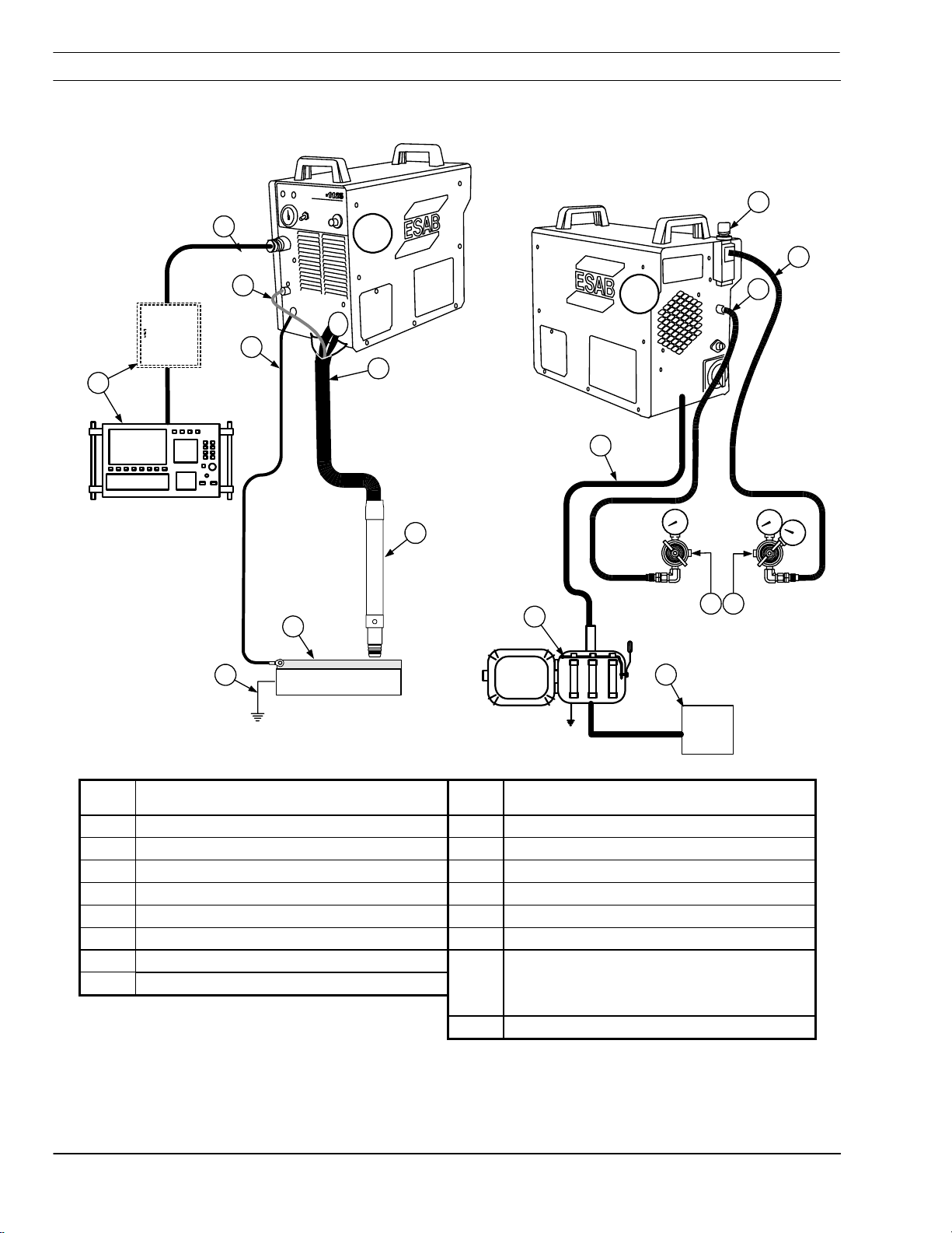
2.1.1 Interconnecting Diagram
EEEE
ttttcccc
hhhh
AAAA
rrrr
cccc
2
F
9
10
3
B
4
1
7
8
5
12
6
15
13
16
11
14
F
EtchArc----1125 Front Connections
EtchArcEtchArc
1125 Front Connections
1125 Front Connections1125 Front Connections
B
EtchArc
EtchArc----1125 Back Connections
EtchArcEtchArc
1125 Back Connections
1125 Back Connections1125 Back Connections
EtchArc
1 Vision CNC (relay box) 9 Air Regulator
2 CNC Control Cable 10 Air Supply Hose
3 Argon Gas Hose to torch 11 Argon Supply Hose
4 Work Cable 12 Primary Power Cable
5 Torch Bundle 13 Argon Gas Supply
6 Marking Torch 14 Compressed Air Supply
7 Work Piece
8 Earth Ground
15
16 Wall disconnect
EtchArc-1125 Plasma Marking System 2-2
Fused Disconnect (mounted on
machine, used when EtchArc-1125
has been mounted on the machine)

SECTION 2 System Description
2.2 System Description
2.2.1 EtchArc Systems
Includes power supply, torch and necessary cables
and hoses.
19 ft. (5.8 m) P/N 0560989772
25 ft. (7.6 m) P/N 0560989773
40 ft. (12.2 m) P/N 0560989774
50 ft. (15.2 m) P/N 0560989775
2.2.2 EtchArc-1125 Power Supply
208/230 V, 50/60Hz, 1 or 3 phase
208/230 V, 50/60Hz, 1 or 3 phase P/N 0588000967
208/230 V, 50/60Hz, 1 or 3 phase208/230 V, 50/60Hz, 1 or 3 phase
460 V, 50/60 Hz, 3 phase
460 V, 50/60 Hz, 3 phase P/N 0588000949
460 V, 50/60 Hz, 3 phase460 V, 50/60 Hz, 3 phase
575 V, 60 Hz, 3 p
575 V, 60 Hz, 3 phase
575 V, 60 Hz, 3 p575 V, 60 Hz, 3 p
Rated Inputs
Rated Inputs Rated Outputs
Rated InputsRated Inputs
hase P/N 0588000966
hasehase
Rated Outputs
Rated OutputsRated Outputs
Phases
Phases Volts
PhasesPhases
Volts Amps
VoltsVolts
1
3
Amps
AmpsAmps
Power
Power Power
Factor
Factor
FactorFactor
Duty Cycle
Duty Cycle
Duty CycleDuty Cycle
Output Amps*
Output Amps*
Output Amps* Output Amps*
@ 120 VDC
@ 120 VDC
@ 120 VDC@ 120 VDC
Open Circuit
Open Circuit
Open Circuit Open Circuit
Voltage
Voltage
VoltageVoltage
Power
64
208
73% 100% 35* 280 VDC
55
58
230
73% 100% 35* 270 VDC
55
208 28 100% 100% 35* 285 VDC
230 25 100% 100% 35* 275 VDC
460 14 100% 100% 35* 285 VDC
575 11 100% 100% 35* 260 VDC
* Output amperage is limited by the marker control
board (P/N 38138) to 35 amperes.
EtchArc-1125 Plasma Marking System 2-3
SECTION 2 System Description
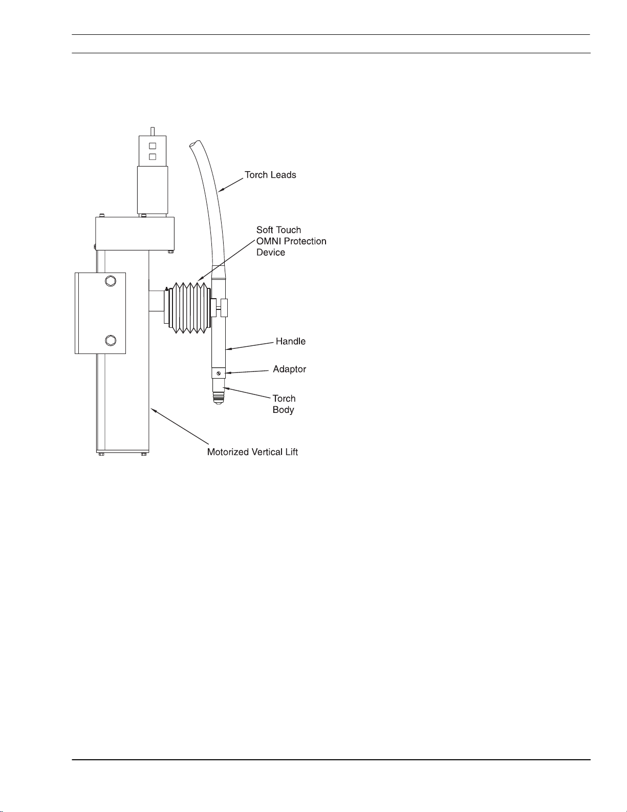
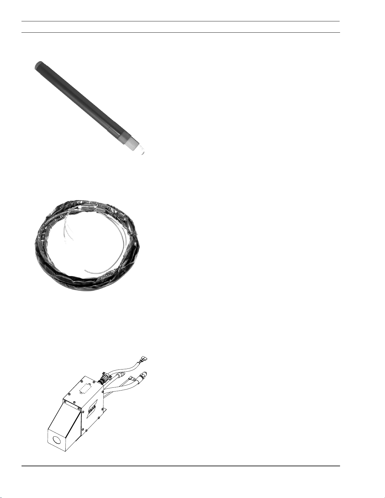
2.2.3 PM60 Plasma Marker Torch Assembly
P/N 0560988474
Gas
Gas Dual (Argon and Air)
GasGas
Cooled
Cooled Air
CooledCooled
Amperes
Amperes Variable -- 35 Amperes Maximum
AmperesAmperes
2.2.4 PM60 Torch Lead Assembly
2.2.5 Option
Remote Arc Starter
Remote Arc Starter
Remote Arc StarterRemote Arc Starter
(Required if torch lead to exceed 50 ft.)
19 Ft.
19 Ft.
19 Ft.19 Ft.
25 ft.
25 ft. P/N 0560986664
25 ft.25 ft.
40 ft.
40 ft. P/N 0560987587
40 ft.40 ft.
50 ft.
50 ft. P/N 0560986685
50 ft.50 ft.
P/N 0560988947
P/N 0558002819
EtchArc-1125 Plasma Marking System 2-4
SECTION 3 Installation
3 Installation
Electric Shock Can Kill!
WARNING
!
Ensure primary power source is off
Ensure primary power source is off
Ensure primary power source is off Ensure primary power source is off
and disconnected before making any
and disconnected before making any
and disconnected before making any and disconnected before making any
electrical connections.
electrical connections.
electrical connections. electrical connections.
Only a qualified technician should
Only a qualified technician should
Only a qualified technician should Only a qualified technician should
install and service this equipment.
install and service this equipment.
install and service this equipment. install and service this equipment.
CAUTION
!
Ensure Your EtchArc-1125 is
being supplied with the
appropriate power.
This equipment comes in 208/230
VAC 1-phase, 208/230 VAC 3-phase,
460 VAC 3-phase and 575 VAC 3phase. Connecting to incorrect
power could damage your machine.
EtchArc-1125 Plasma Marking System 3-1
SECTION 3 Installation
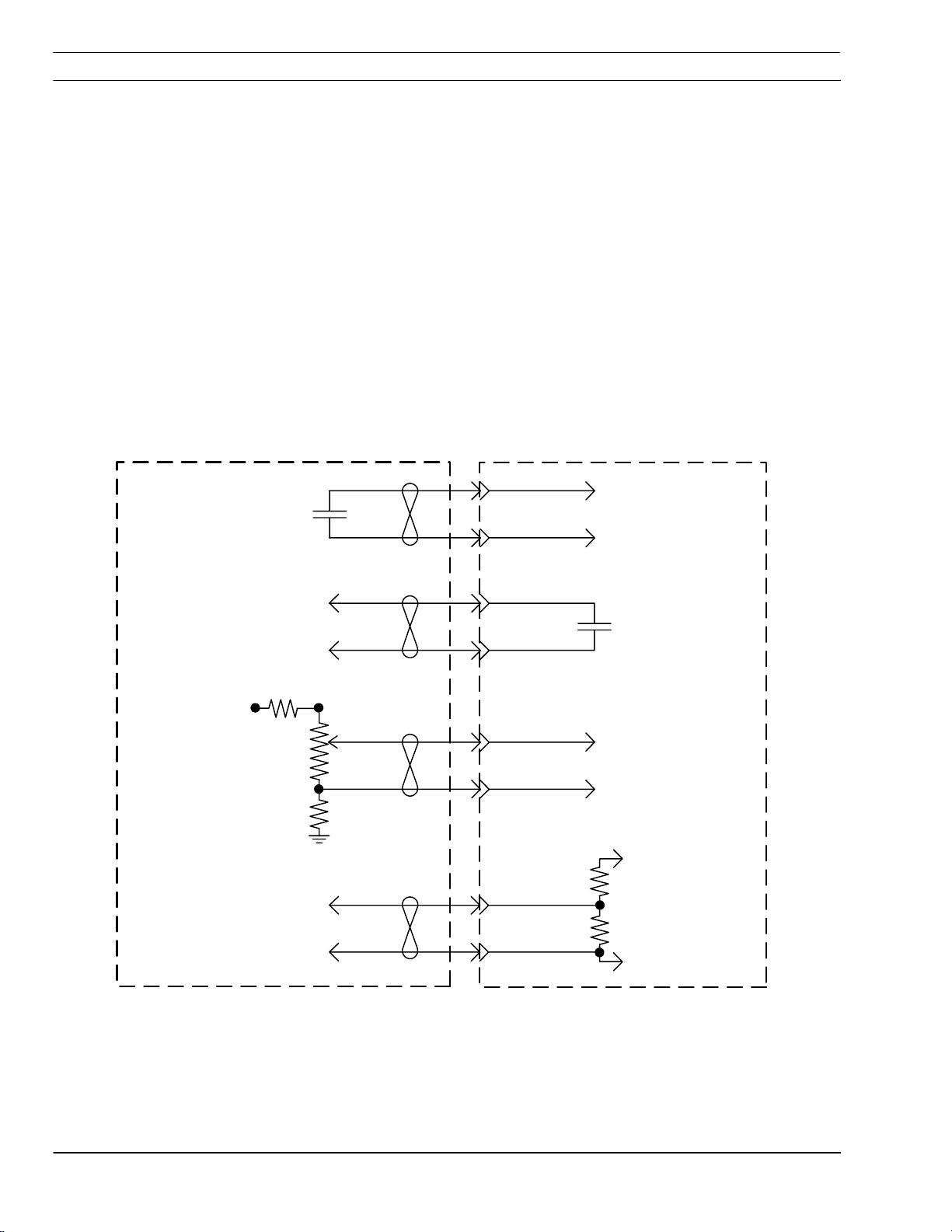
3.1 Interface
The EtchArc Plasma Marker system interfaces with
any cutting machine controller via the standard ESP
open interface. This interface provides an
amphenol connector for linking the appropriate
control wiring.
The schematic below illustrates interfacing with an
EtchArc and ESAB Vision or ESAB Series 2000
CNC. The customer must provide the external
requirements shown below when interfacing with a
control other than these types.
External
Requirements
Start signal (Close
contacts to start
arc)
ESP Interface
Plug (J2)
J2-N
J2-M
EtchArc-1125
Power Supply
Start signal to
power supply
Arc ON signal to
CNC
Current control
signal (Variable
DC Voltage)
Vmax = 3.5 V
Vmin = 0.3 V
Voltage divider
signal to voltage
height control
(+)
(-)
J2-I
J2-G
J2-L
J2-J
J2-C
J2-H
ESP Interface
Contact closes
when arc starts
(+)
3.5 V = 35 A
0.3 V = 3.0 A
(-)
Work
20:1
Electrode
EtchArc-1125 Plasma Marking System 3-2
SECTION 3 Installation
3.2 Requirements
Electrical Input Requirements
Rated primary input @ 35A / 120V output:
A fused breaker (either on the cutting machine
Recommended sizes for input conductors and
• 208/230VAC, 1 Phase 64/58A, 50/60 Hz.
• 208/230/400/575 VAC, 3 Phase
28/25/16/11A, 50/60 Hz.
gantry or wall mounted) is required to disconnect
power to the EtchArc-125 power supply. A
machine mounted disconnect should be used when
the power supply is mounted on the cutting
machine.
line fuses:
Rated Input Input & Gnd
Conductor
Volts Amps Phase CU/AWG Amps
208 64 1 No. 4 90
230 58 1 No. 4 90
208 28 3 No. 10 50
230 25 3 No. 10 40
400 16 3 No. 10 25
575 11 3 No. 10 20
Fuse Size
Gas Supply Requirements
Argon 100 psi (¼ NPT)
99.999% Pure
Service Air 100 psi (¼ NPT)
Clean, dry, oil-free
EtchArc-1125 Plasma Marking System 3-3

SECTION 3 Installation
3.3 Connections to the EtchArc-1125
3.3.1 Back
Shield Gas (Air)
Primary Power
Plasma Gas
(Argon)
There are 3 input lines to connect to the power
supply. These are made to the back of the unit
• Shield Gas
• Plasma Gas
• Primary power
Shield Gas
Shield Gas
Shield GasShield Gas
Prefiltered (clean and dry) Air) customer supplied,
90 to 150 PSI max. ¼ NPT
Plasma Gas
Plasma Gas
Plasma GasPlasma Gas
99.999% purity, 100 PSI, ¼ NPT
Primary Power
Primary Power
Primary PowerPrimary Power
3 prong plug used on
the single phase
208/230 VAC EtchArc-
1125
Red lead terminated and
not used on the
1-phase EtchArc-1125
Inside the 3 prong plug
208/230 VAC unit is supplied with a 3-prong plug
on a 10 ft. power cable when used as a single
phase EtchArc power supply. If used as a 3-phase
unit, disassemble plug and discard. Un-tape red
lead and connect.
The EtchArc 460 and 575 VAC power supplies are
3-phase and must be hard wired into the wall
disconnect box.
EtchArc-1125 Plasma Marking System 3-4

SECTION 3 Installation
3.3.2 Converting a 230 VAC power supply to 208 VAC
D2 D1
TB5-2
TB5-1 Gray Lead
TB3
The EtchArc-1125 is factory wired for 1-phase 230
volts AC. If using 208 VAC, the EtchArc must be
reconnected as follows before connecting to your
input primary power.
A. Remove cover from the EtchArc Power
Supply.
B. Locate output bridge (D2) and TB3 on left
side towards the front panel.
C. Disconnect X2 and X3 leads from these two
locations and interchange wire connections.
D. Move X2 from D2-3 to TB3.
E. Move X3 lead that was on TB3 to D2-3.
F. Locate the input bridge (IBR) and TB5
terminal block on the left side towards the
rear panel.
G. Disconnect gray lead from TB5-2 and
reconnect to TB5-1
TB5-2 to TB5-1
EtchArc-1125 Plasma Marking System 3-5

SECTION 3 Installation
3.3.3 Torch Lead Connections to EtchArc-1125
Torch Lead Bundle
Torch Lead
Connections
Shield Gas Hose/
Plasma Arc Lead
Argon Hose (Cut Gas)
Pilot Arc Cable
The torch lead bundle consists of;
one hose for the plasma gas,
one cable for the pilot arc current,
and one combination gas hose and cable for the
shield gas/plasma current. (The current conductor
is inside the air shield gas hose).
The torch lead to torch connections are covered in
section 3.3.4
Torch Lead Connection Access Panel
Remove the torch lead connection access panel to
connect the shield gas and pilot arc cable.
EtchArc-1125 Plasma Marking System 3-6

SECTION 3 Installation
Pilot Arc
Connection
Shield Gas
Connection
Connect pilot arc cable and shield gas hose. (The
plasma arc connection is made when the shield
gas hose is threaded into the bulkhead fitting.)
Connect plasma gas hose the bulkhead.
Replace access panel.
Plasma Gas Connection (Argon)
EtchArc-1125 Plasma Marking System 3-7
SECTION 3 Installation
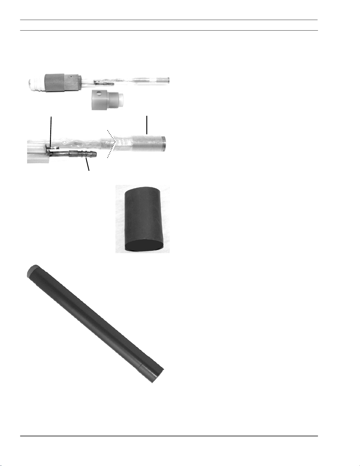
3.3.4 Torch Bundle To Torch
Handle adapter removed for illustration
Pilot Arc ShieldGas/
Plasma Gas
1 ½” dia. heat shrink
Power
The torch has three connection points.
• Shield Gas (Air)/Plasma Arc
• Pilot Arc
• Plasma Gas
Procedure
A). Unscrew handle from marker torch. Slide two
(2) pieces of black heat shrink (provided— 1 ½ dia)
onto the torch bundle.
B). Slide the torch handle on the torch bundle far
enough to allow access to connection points. This
may require a slight back and forth twisting motion
of the handle.
EtchArc-1125 Plasma Marking System 3-8

SECTION 3 Installation
2
C). Shield Gas/Power Connection
Shield Gas/Power Connection
Shield Gas/Power Connection Shield Gas/Power Connection
• Slide two (2) pieces of clear ¾ KYNAR heat
shrink on to the air/power connection of the
1
torch body as shown.
• Tighten the Air/Power Hose to the torch
2
connection.
1
• Position 1 piece or heatshrink over the
air/power connection so that all metal is covered
and shrink into place.
• Repeat procedure with the second piece of
heatshrink.
Shield
Gas/Plasma
Arc
EtchArc-1125 Plasma Marking System 3-9

SECTION 3 Installation
4
3
Cut Gas (Argon)
D. Cut Gas hose connection
Cut Gas hose connection
Cut Gas hose connectionCut Gas hose connection
• Assemble 2 pieces of ½ X 3 of Kynar
heatshrink on to the argon hose .
3
4
• Trim argon hose to length.
• Position cut gas hose clamp on to argon hose
about 1 to 2 inches past end of hose as shown.
• Slip hose on barbed fitting of torch body.
• Position clamp over barb and hose with
oreientation of clamp ears as shown .
10
• Position 1 piece of heatshrink over clamp and
hose.
• Shrink into place. Repeat.
10
EtchArc-1125 Plasma Marking System 3-10

SECTION 3 Installation
7
6
E. Pilot Arc Connection
Pilot Arc Connection
Pilot Arc ConnectionPilot Arc Connection
• Remove H.F. connector from pilot arc
5
cable and place on arc wire of torch body to
determine pilot arc cable length.
• Trim, strip and re-tin end of pilot arc cable.
5
• Remove from torch body and reassemble
cable connector to pilot arc cable.
• Tighten set screw.
• Place 2 -- 3 long pieces of 3/8 diameter
Kynar heatshrink onto pilot arc cable .
6
7
• Assemble H.F. connector to body and tighten
setscrew.
• Position 1 piece of heatshrink over the
connector and shrink in place. Repeat
Pilot Arc
EtchArc-1125 Plasma Marking System 3-11

SECTION 3 Installation
H). Using a slight back and forth twisting motion,
slide the torch handle to the torch body handle
adapter.
I). Remove screw from torch handle adapter
J). Holding torch handle stationary, thread handle
adapter into handle.
Do not rotate handle or torch body
CAUTION
to thread into adapter. This may
twist the bundle components inside
Hold handle stationary.
Do not rotate.
Rotate torch adapter to
thread into sleeve
handle and damage torch.
Hold torch body
stationary. Do not
rotate
EtchArc-1125 Plasma Marking System 3-12

SECTION 3 Installation
K). Replace screw.
L). Position 1 ½ diameter heat shrink over the end
of the torch handle as shown and shrink with heat
until tight. Shrink one piece in place. Slide second
into position and shrink with heat.
Torch
Bundle
Heat shrink Torch
Handle
EtchArc-1125 Plasma Marking System 3-13

SECTION 3 Installation
This page intentionally left blank.
EtchArc-1125 Plasma Marking System 3-14

SECTION 4 Operation
4 Operation --Setup
4.1 EtchArc-1125 Setup
The ETCHARC-1125 control panel should be set
properly before the marking operation. Check the
following items:
GAS TEST - Place this switch in the OPERATE
POWER
PRESSURE
(70 psig)
CNC
AIR
FAULT
EtchArc-1125
GAS
TEST
OPERATE
10
5
CURRENT
CONTROL
15
A
0
20
25
30
35 MAX
position for normal operation. TEST position
energizes the gas solenoids to allow presetting of
the argon and air gases.
CURRENT CONTROL - The Current Control knob
can be left in any position. This potentiometer is
normally disconnected for remote current control.
(Plasma Marking current is controlled by the cutting
machine CNC.) If the control does not support
remote current, the current control potentiometer
can be reconnected. (Wiring Diagrams in Section 6)
POWER - The Power On lamp should be on.
FAULT - The Fault lamp should be off.
ARGON
WORK
TORCH
EtchArc-1125 Plasma Marking System 4-1

SECTION 4 Operation
4.2 Gas Setup
Test/Operate Switch
Air Pressure
Gage
Air Pressure Regulator
Argon Pressure Gauge
Argon Pressure
Regulator
The plasma marking system uses two compressed
gases for operation. Compressed air is used for
electrode cooling and shield gas, argon is used as
plasma gas. The plasma gas constricts the arc as it
exits through the nozzle orifice. The shield gas
creates a secondary shield around the arc and
improves torch cooling.
Before operating the system, check gas pressure
settings for both compressed gases.
A. Set the Test/Operate switch to the TEST
position to energize the solenoid valves for both
compressed air and argon.
B. Adjust the air pressure regulator on the rear of
the unit while observing the pressure gauge on
the front of the unit. Set pressure to 90 PSI
while the air is flowing.
C. The argon pressure is adjusted at the separate
regulator panel mounted to the cutting machine.
While the argon is flowing, set the pressure to
75 psi.
D. When finished adjusting gas pressures, set the
TEST/OPERATE switch back to the OPERATE
position.
EtchArc-1125 Plasma Marking System 4-2

SECTION 4 Operation
4.3 CNC Setup
Standoff
Initial Height
Plasma Travel
Delay
Marker Remote
Current
The EtchArc plasma marker may be interfaced to
any cutting machine CNC. The following
parameters may or may not be supported by your
interface. Before plasma marking, check these
parameters, or their equivalents, at the machine
control:
On the Vision CNC, this parameter adjusts the
actual cutting height (or arc voltage) the torch will
maintain after the arc has started.
Sets the distance the torch will be raised after
sensing the plate. When VHC is turned on, the
torch will lower to the plate, then retract this
distance before starting the arc.
Sets the length of time the machine will remain
motionless after the arc strikes. Set to zero for the
plasma marking process.
This parameter sets the marking current in
amperes.
These parameters are preset when using SDP*
marker files.
*The Vision family of CNCs allows the user to store
multiple process parameter files. The files, called
SDP files (ScheidDatenPaket = Cutting data
package), contain all the same information that can
be manually adjusted on the process parameter
screen. (See your programming manuals for more
information)
EtchArc-1125 Plasma Marking System 4-3

SECTION 4 Operation
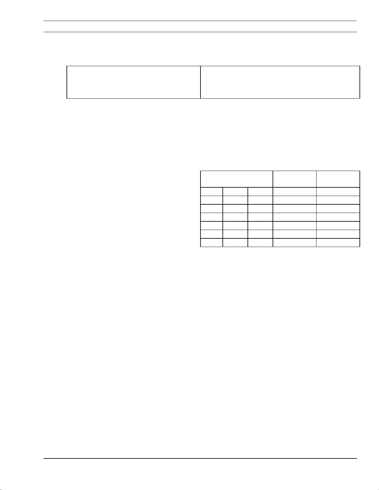
4.4 Process Data
The EtchArc Plasma Marker can produce marked
lines in a wide range of widths and depths, ranging
from poor to excellent quality. It can also operate
over a wide range of speeds. The operator must
balance these two factors based on the
requirements for a specific job.
The following pages provide process data for the six
different amperage settings. Each page shows the
setup parameters for that amperage and a chart
with marking speed range. From the chart, the
operator should select the speed setting based on
the quality of mark that can be accepted.
EtchArc-1125 Plasma Marking System 4-4

SECTION 4 Operation
10 Amp Marking
Electrode
2237857
Nozzle
56996876
CURRENT:
NOZZLE:
MATERIAL:
PLASMA GAS:
SHIELD GAS:
PIERCE HEIGHT:
ARC VOLTAGE:
10 Amps
.030 PN: 56996876
CARBON STEEL
ARGON @ 75 PSI (5 bar)
AIR @ 90 PSI (6 bar)
.125 (3 mm)
66
Shield Cup
2237859
Travel Plasma
Speed Mark
inch/min mm/min Width Depth Quality
100 2540 .040-.050 .0013 FAIR
200 5080 .040-.050 .0005 GOOD
300 7620 .040-.050 .0004 GOOD
400 10160 .040-.050 .0004 EXCELLENT
500 12700 .040-.050 .0003 EXCELLENT
Notes
1. Corner current set for 5 Amps in machine MIP.
2. Slow travel speeds usually have top spatter on mark edges.
3. Width and depth of mark will vary slightly depending on measuring methods. This information is for
estimated results.
EtchArc-1125 Plasma Marking System 4-5

SECTION 4 Operation
15 Amp Marking
Electrode
2237857
Nozzle
56996876
CURRENT:
NOZZLE:
MATERIAL:
PLASMA GAS:
SHIELD GAS:
PIERCE HEIGHT:
ARC VOLTAGE:
15 Amps
.030 PN: 56996876
CARBON STEEL
ARGON @ 75 PSI (5 bar)
AIR @ 90 PSI (6 bar)
.125 (3 mm)
66
Shield Cup
2237859
Travel Plasma
Speed Mark
inch/min mm/min Width Depth Quality
100 2540 .040-.050 .0043 POOR
200 5080 .040-.050 .0021 FAIR
300 7620 .040-.050 .0013 GOOD
400 10160 .040-.050 .0003 EXCELLENT
500 12700 .040-.050 .0002 EXCELLENT
Notes
1. Corner current set for 5 Amps in machine MIP.
2. Slow travel speeds usually have top spatter on mark edges.
3. Width and depth of mark will vary slightly depending on measuring methods. This information is for
estimated results.
EtchArc-1125 Plasma Marking System 4-6

SECTION 4 Operation
20 Amp Marking
CURRENT:
20 Amps
Electrode
2237857
Nozzle
56996876
NOZZLE:
MATERIAL:
PLASMA GAS:
SHIELD GAS:
PIERCE HEIGHT:
ARC VOLTAGE:
.030 PN: 56996876
CARBON STEEL
ARGON @ 75 PSI (5 bar)
AIR @ 90 PSI (6 bar)
.125 (3 mm)
66
Shield Cup
2237859
Travel Plasma
Speed Mark
inch/min mm/min Width Depth Quality
200 5080 .040-.050 .0028 POOR
300 7620 .040-.050 .0011 FAIR
400 10160 .040-.050 .0008 GOOD
500 12700 .040-.050 .0002 GOOD
Notes
1. Corner current set for 5 Amps in machine MIP.
2. Slow travel speeds usually have top spatter on mark edges.
3. Width and depth of mark will vary slightly depending on measuring methods. This information is for
estimated results.
EtchArc-1125 Plasma Marking System 4-7

SECTION 4 Operation
25 Amp Marking
Electrode
2237857
Nozzle
56996876
CURRENT:
NOZZLE:
MATERIAL:
PLASMA GAS:
SHIELD GAS:
PIERCE HEIGHT:
ARC VOLTAGE:
25 Amps
040 PN: 2237858
CARBON STEEL
ARGON @ 75 PSI (5 bar)
AIR @ 90 PSI (6 bar)
.125 (3 mm)
66
Shield Cup
2237859
Travel Plasma
Speed Mark
inch/min mm/min Width Depth Quality
200 5080 .050-.060 .0051 POOR
300 7620 .050-.060 .0034 FAIR
400 10160 .050-.060 .0032 GOOD
500 12700 .050-.060 .0014 GOOD
Notes
1. Corner current set for 5 Amps in machine MIP.
2. Slow travel speeds usually have top spatter on mark edges.
3. Width and depth of mark will vary slightly depending on measuring methods. This information is for
estimated results.
EtchArc-1125 Plasma Marking System 4-8

SECTION 4 Operation
30 Amp Marking
Electrode
2237857
Nozzle
2237858
CURRENT:
NOZZLE:
MATERIAL:
PLASMA GAS:
SHIELD GAS:
PIERCE HEIGHT:
ARC VOLTAGE:
30 Amps
.040 PN: 2237858
CARBON STEEL
ARGON @ 75 PSI (5 bar)
AIR @ 90 PSI (6 bar)
.125 (3 mm)
66
Shield Cup
2237859
Travel Plasma
Speed Mark
inch/min mm/min Width Depth Quality
200 5080 .050-.060 .0033 POOR
300 7620 .050-.060 .0030 FAIR
400 10160 .050"-.060 .0023 FAIR
500 12700 .050-.060 .0029 GOOD
Notes
1. Corner current set for 5 Amps in machine MIP.
2. Slow travel speeds usually have top spatter on mark edges.
3. Width and depth of mark will vary slightly depending on measuring methods. This information is for
estimated results.
EtchArc-1125 Plasma Marking System 4-9

SECTION 4 Operation
35 Amp Marking
Electrode
2237857
Nozzle
2237858
CURRENT:
NOZZLE:
MATERIAL:
PLASMA GAS:
SHIELD GAS:
PIERCE HEIGHT:
ARC VOLTAGE:
35 Amps
.040 PN: 2237858
CARBON STEEL
ARGON @ 75 PSI (5 bar)
AIR @ 90 PSI (6 bar)
.125 (3 mm)
66
Shield Cup
2237859
Travel Plasma
Speed Mark
inch/min mm/min Width Depth Quality
300 7620 .050-.060 .0012 POOR
400 10160 .050-.060 .0024 FAIR
500 12700 .050-.060 .0032 FAIR
Notes
1. Corner current set for 5 Amps in machine MIP.
2. Slow travel speeds usually have top spatter on mark edges.
3. Width and depth of mark will vary slightly depending on measuring methods. This information is for
estimated results.
EtchArc-1125 Plasma Marking System 4-10

SECTION 5 Maintenance
5 Maintenance
The Plasma Marking System consists of an
EtchArc-1125 plasma power supply, the marking
torch and argon supply.
Electric Shock Can Kill or Injure!
WARNING
!
Ensure the wall disconnect switch (or Circuit
breaker) is open before removing cover or
doing maintenance.
Electric Shock Can Kill!
WARNING
!
Ensure power supply power switch is OFF
before servicing the PM-60 EtchArc Torch.
EtchArc-1125 Plasma Marking System 5-1

SECTION 5 Maintenance
5.1 Routine Maintenance
CAUTION
!
The following routine maintenance should be
performed on the plasma marker system.
Compressed Air May Displace Debris
Causing Eye Injuries.
Always wear approved safety eye and face
protection whenever using compressed air to
clean equipment. Dust and debris can be
deflected back towards the face, possibly
resulting in a serious eye injury. Ensure
others nearby are protected also.
CAUTION
Water And Oil Contaminants in
Compressed Air May Damage Power
Supply Components.
Shop air occasionally contains accumulated
oil or water. Before using compressed shop
air to clean the interior of the power supply,
redirect the first air blast away from power
supply.
• Inspect the supply hoses, torch leads, ground
cable and interface cables for damage or wear
weekly.
• Inspect and clean the EtchArc-1125 monthly.
The unit can be blown out using a clean, dry
gas source, such as compressed air or
nitrogen.
• Occasionally drain all water from beneath the
air filter-regulator.
EtchArc-1125 Plasma Marking System 5-2

SECTION 5 Maintenance
Flow Switch
The Flow Switch (P/N 951202) may need to be
cleaned if excessive contamination is found in the
air supply.
Flow Switch Location
Piston Plug
Spring
Piston
Flow Switch Body
Note: The flow switch can be disassembled and
cleaned without extraction from the power supply.
1) Turn Off power supply
2) Remove piston plug
3) Remove the spring. Use care when handling
spring to prevent distortion.
4) Remove the piston.
5) Clean all parts with warm water and a mild
detergent. Allow parts to dry thoroughly before
reassembly.
6) Reassemble switch in reverse order.
EtchArc-1125 Plasma Marking System 5-3

SECTION 5 Maintenance
This page intentionally left blank.
This page intentionally left blank.
This page intentionally left blank.This page intentionally left blank.
EtchArc-1125 Plasma Marking System 5-4

SECTION 6 Troubleshooting
6 Troubleshooting
WARNING
!
WARNING
!
Electric Shock Can Kill!
Ensure that all primary power to the
machine has been externally
disconnected.
Open the line (wall) disconnect switch or
circuit breaker before attempting
inspection or work inside the power
supply.
High Voltages Can Cause Serious
Injury Or Death.
Voltage in plasma equipment is high
enough to cause serious injury or death.
Be particularly cautious when around
equipment when covers are removed.
6.1 Troubleshooting Guide
Power Light Does Not Come on.
Location of fuse (F1)
A) Visually inspect the machine for damage.
B) Check if the cooling fan is running. If not, then check the
following:
B1) Check if the machine power cord is plugged into the input
power receptacle.
B2) Measure the input power at the receptacle. If not present,
check the wall disconnect switch and related fuses.
B3) Check fuse (F1). If fuse is ok, check the input circuit breaker
(CB1) for proper operation. Replace if defective.
C) If above items check OK, the problem is internal. Send unit to
an Authorized Repair Station.
C1) If cooling fan is running, measure voltage between pins
P2-11 and P2-14 of the control board. Should be 115 VAC. If
there is no voltage, then replace transformer T2.
C2) If voltage is present, the pilot light may be burned out.
EtchArc-1125 Plasma Marking System 6-1

SECTION 6 Troubleshooting
No air flow.
Over Temperature
• Check air inlet supply. Unit requires 320 CFH at 65 psig.
• Check air hose connections.
• Does air flow when “air test” switch is in test position?
o If not, check torch consumables, replace if
necessary.
o If above items check OK, the problem is internal.
Take unit to an Authorized Repair Station.
• The fault light will be illuminate for 1/10 of a second every
second. This generally indicates that the air flow has been
blocked. Clear blockage and allow the power supply to cool
before operating.
• Thermal switch may be open. It will open if the heat sink
temperature reaches 80 degrees C. With the machine power off,
check the continuity between P1-1 and P1-2 of the control board.
If the switch is OK, then the ohmmeter should read a direct short.
If not, then it should read open.
Over current.
Arc does not transfer to plate.
• If the switch is malfunctioning, replace it. Clean the surface of
the heat sink before installing switch.
• The fault light will be continuously illuminated. This indicates
the input current to the main transformer has exceeded preset
limits.
• To check if the output is shorted, measure resistance by
putting ohmmeter leads (ensure HI Freq leads are disconnected)
“+” of the meter to torch, “+” output terminal and work, “-“ lead of
the meter to the “-“ output terminal. Reading should be about 2K
OHMS. Reverse the voltmeter leads, the resistance reading
should be less than 1.5 OHMS.
• Resistance reading is different than above, check torch, the
output bridge and filter board (PCB5).
• Make sure work clamp has a good connection to material to
be marked.
• Check consumables. Replace if necessary.
EtchArc-1125 Plasma Marking System 6-2

SECTION 6 Troubleshooting
Poor marking performance
• Check gas regulators. Should be set to 65 to 70 psig.
• The air supply should be free of oil/water.
• Check condition of consumables.
• Check open circuit voltage.
o With high frequency leads disconnected, measure
open circuit voltage. It should be 275 VDC between
“Work” and “Torch” terminals. If not then check one of
the following:
o Check operation of the Thermal Switch. (See Over
Temperature)
Gas does not shut off.
o Check Air Flow Switch for internal short. Should have
Fault Light. Light blinking off for 1/10
th
second every
second indicates low air flow. Put the Gas Test
Switch to TEST. Air should flow through torch. If not
then the flow switch may be stuck in the open
position. To check if switch is open, put voltmeter
leads between P1-12 and P1-1. It should read about
12VDC. When switch closes, voltage drops to zero
volts. Clean or replace switch. (see instructions in
Section 5)
• Check gas solenoids for operation.
• Does gas flow when CNC cable is unplugged. If yes, repair
torch. If no, send unit to an authorized repair station for repair.
• C) Check voltage to solenoid coils. If present when start
contact is disconnected, replace PCB1 (marker board). If voltage is
“0”, replace solenoid valve.
EtchArc-1125 Plasma Marking System 6-3

SECTION 6 Troubleshooting
Fault light activates when start
contacts are closed.
The fault light is used to monitor conditions necessary for the safe
operation if the EtchArc-1125. The fault light will glow amber under
the following conditions and the unit will stop working:
• High/Low Voltage
High/Low Voltage. The fault light will rapidly blink on and off (5
High/Low VoltageHigh/Low Voltage
times per second). This indicates that the input voltage is outside
the “+” or “-“ 15% safe operating range.
• Flow Fault
Flow Fault. The fault light will be mostly on but will blink off for
Flow FaultFlow Fault
1/10 of a second every second. This indicates the gas flow is low.
o B1) Check gas pressure at the machine regulator. It
should be adjusted to 65 psig. If no gas pressure,
check the gas at the supply point. Also check for
obstructions in the gas hose.
o B2) Gas flow may be blocked at the torch tip. Check
torch consumables. Also check for any obstructions in
the torch leads.
• Note. If above items check OK, the problem is internal will have
to be sent to an authorized repair station.
o B3) Put the Gas Check switch to the on position. Gas
should flow through the torch. If not, then the flow
switch may be stuck due to oil or dirt in the gas. Clean
flow switch per instructions in the maintenance section
or replace switch. To check if the flow switch is open,
put a voltmeter leads between P1-12 and P1-1. It
should read 12VDC. When the switch closes, voltage
will drop to “0”.
o B4) Gas Test Switch may be malfunctioning.
EtchArc-1125 Plasma Marking System 6-4

SECTION 6 Troubleshooting
Gas is on but nothing
happens when start contacts
are closed.
• Check the pilot arc fuse located on the rear panel. If open,
replace.
• Check to ensure high frequency is present at the torch. If not,
then listen for high frequency at the high frequency generator. It is
located on the bottom/right side of the unit. The high frequency gap
is to 0.030 inches. Disconnect HI Frequency leads. Check for 115
supply voltage between P2-12 and P2-13 of the control board.
• With high frequency leads disconnected, measure open circuit
voltage. It should e 275 VDC between “work” and Torch terminals.
If not present, then any on of the following may not be working
properly:
• Check for operation of the thermal switch. (see over voltage)
• Check Gas Check switch operation. It might be stuck in the ON
position. Pilot arc will not initiate if the switch is in the ON position.
• Check Gas flow Switch. There may be an internal short.
• Measure voltage across C1 and C2 capacitors. It should be as
follows:
o Measure voltage across C1 and C2 capacitors.
Readings should be as follows:
§ approx. 294 VDC with 208v unit
§ approx. 325 VDC with a 230v unit
§ approx. 325 VDC with a 460v unit
§ approx. 400 VDC with a 575v unit.
• NOTE: If readings are not correct then one of the following
could be malfunctioning.
• Check capacitors C1 and C2 for damage.
• Check input bridge/SCR Module (IBR). Replace if
malfunctioning.
• Check Inrush Current Resistor, R10 and SCR1. Both are
located on the input bridge heat sink. Replace if necessary.
• Check current output. Use a calibrated current probe capable of
measuring 100 amps in the presence of high frequency.
Main arc is difficult to start
• Worn of missing consumables. Check and replace if necessary.
• Input gas (argon or air) must be clean and dry.
• Input air pressure is between 65 and 75 psig.
• Torch connections must be tight
• Work cable or clamp must make a good electrical connection to
the material to be marked.
• Initial height is too far from plate. (see marking data for
recommended distances)
• Pilot arc is missing or weak.
• Check spark gap
• Check pilot arc fuse
EtchArc-1125 Plasma Marking System 6-5

SECTION 6 Troubleshooting
6.2 System Schematic 208/230V P/N 0588000967
BLK
L1
T1 T2
3
3
M
M
V
V
O
O
275V275V
I
I
B
B
(+)(+)
1
1
0
0
R
R
22
10,50W10,50W
(+)(+)
C2E1C2E1
Q2Q
C2E1C2E1
11
39K,2W39K,2W
22
40UF,400VDC40UF,400VDC
208/230208/230
Schematic Page 1 of 2
VAC
50/6050/60
HZ
RED
L2
1 AND 31 AND 3
PH
M
M
2
2
M
M
V
V
O
O
275V275V
275V275V
AC3AC3
D6D6
R
R
D5D5
GG
11
Q1Q
R9R9
C4C4
RR
D4D4
R2R2
5
5
1
1
R
R
2
R2R
1
G1G1
E1E1
P1-4P1-4
V V
P1-4P1-4
G1G1
E1E1
2
33
44
L3
T3
1
1
V
V
O
O
AC2AC2
TT
SS
C3C3
C1C1
1800UF,450VDC1800UF,450VDC
C2C2
1800UF,450VDC1800UF,450VDC
2
B
C
P
2
B
C
P
V V
P1-3P1-3
3
3
B
C
P
B
C
P
P1-3P1-3
0.022UF,1KV0.022UF,1KV
1010
OHM,50W
WHT
AC1AC1
D3D3
(-)(-)
D2D2
D1D1
1
1
C
C
10K,25W10K,25W
10K,25W10K,25W
1UF,600V1UF,600V
G2G2
P1-1P1-1VP1-2P1-2
V
P1-1P1-1VP1-2P1-2
G2G2
C10C10
R7R7
1010
S1S
9
9
V
1
.22UF,1KV.22UF,1KV
22
11
208V208V
H2H2
208V208V
X6X6
X5X5
12V12V 24V24V
V V V V
P1-5P1-5
M
M
Control
Board
P
P
3
8
8 ,
300W
R12
K
K
R
R
W
W
O
O
(-)
3
3
H2H2
230V230V
TB5-2TB5-2
H3H3
230V230V
P1-6P1-6
r
r
a
a
/
/
N
N
1
V
400V400V
H4H4
X8X8
X7X7
P2-1P2-1
k
e
r
k
e
r
3
8
R13
.82UF
630VDC
K1
L3
T3
P.A.P.A.
P1-1P1-1
P
B
C
P
B
C
TB5-1TB5-1
22
11
1
M1M
H1H1
00
T2T2
F1F1
3A,600VAC3A,600VAC
22 11
X2X2
2
L2L
X1X1
R1R1
10K,2W10K,2W
MAXMAX
11
22
33
C16C16
SEE NOTE 1
C15C15
11
1UF1UF
600V600V
H1H1
1
T1T
22
H2H2
1
1
S
S
T
T
22
X3X3
230V230V
208V208V
X2X2
230V230V
X1X1
E2E2
22
C1C1
33
E2E2
(-)(-)
E2E2
C1C1
33
E2E2
22
1uf1uf
600V600V
11
4
T4T
TB3TB3
R5
11122
R3R3
11
20,25W20,25W
V V
V V
V
V V
V V V V
V V V V V
V
22
.01UF,1KV.01UF,1KV20,25W20,25W
(+)(+)
1
22
.01UF,1KV.01UF,1KV
X1X1
12V12 V
V
P5-3P5-3
P2-5P2-5
P2-6P2-6
P6-13P6-13
P6-14P6-14
P6-12P6-12
P1-1P1-1
P1-2P1-2
P3-2P3-2
P3-1P3-1
P3-3P3-3
P3-4P3-4
P4-4P4-4
P4-3P4-3
P4-1P4-1
P4-2P4-2
P1-7P1-7
P1-8P1-8
C7C7
11
3
3
C5C5
112222 11
.01UF,1KV.01UF,1KV
X2X2
V
P5-4P5-4
22
.01UF,1KV.01UF,1KV
C6C6
X3X3
V
P1-9P1-9
C8C8
11
2
D2D2
D1D1
2
X4X4
18V18V
P1-10P1-10
P6-10P6-10
P6-11P6-11
VV
REDRED BLKBLK
6
R6R
11
22
20,25W20,25W
(-)(-)
R4R4
11 22
20,25W20,25W
X11X11
11
P2-11P2-11
G
G
115V115V
SHS
(+)(+)
N
N
5
H
D
D
H1H1
X12X12
22
44 33
22
0.047uf0.047uf
P2-14P2-14
300W
R11
11
C
2
C
2
660V660V
L1L
8 ,
1
1
2
X10X10
X9X9
20V20V
V
V V V
P2-4P2-4
330K
,1W
C21
K1
T2
L2
5
5
P1-6P1-6
P1-2P1-2
P1-3P1-3
V
P1-3P1-3
P1-4P1-4
PILOT
K1
ARC
T1L1
.022UF,
C20
1KV
GND
3
V V V
3
(+)(+)
4
(-)(-)
5
NOTE 1) Potentiometer is d isconnected. The current
command is provided by the cutti ng machine. On machines
that do not have remote current capabi lities, the POT is
re-connected. (Retro-Fits)
SCHEMATIC
EtchArc-1125 208v/230v
EtchArc-1125 Plasma Marking System 6-6

SECTION 6 Troubleshooting
Page 2 of 2 Schematic
REMOTE
CURRENT
COM SIG
J
1
B
B
T
T
(SEE(SEE
CHART)
4
4
ARC
ON
GL
I
112233
START
M
N
44
2
V V
P6-9P6-9
P6-7P6-7
P2-3P2-3
P2-4P2-4
P1-12P1-12
P1-11P1-11
VDR
(+) (-)
C
HKD
55
66
(+)(+) (-)(-)
V
V
VV
PREFLOW/
GAS
TEST
AIR
11
S
FSF
1
CNC
PLUG
33
22
11
S2
66
55
44
22
PRES.
SW
ARGON
M
a
r
k
e
r
M
a
r
k
e
r
Control
Board
/
/
P
P
N
N
3
8
1
3
8
3
P2-2P2-2
V VV
P2-3P2-3
P5-5P5-5
V
P5-6P5-6
V
P5-1P5-1
V
P5-2P5-2
-
-
1
1
H1H1
X1X1
H2H2
.01UF,250.01UF,250
1
1
1
1
C
C
.01UF.01UF
1KV1KV
11
1
1
C
C
25002500
PF,15KV
X2X2
115115
VAC
VAC
C9C
G
G
T5T
SGS
3
3
9
N
N
4
5
G
T3T
P2-13P2-13
V
D
D
C
C
.01UF.01UF
1KV1KV
3
1
1
P2-12P2-12
V
1
1
B
B
T
T
O
S
O
S
2
2
L
L
P
P
8
8
1
1
C
C
.022UF.022UF
250VAC250VAC
T
T
2
2
H2H2
X2X2
22
C
C
B
B
T
T
H1H1
X1X1
1
L
1
L
N
G
N
G
2
1
1
B
B
4
4
1
1
2
2
11
22
++
C
C
.022UF.022UF
250VAC250VAC
D
D
-
-
2
2
25002500
PF,15KV
C
R
O
T
C
R
O
T
11
75mA75mA
1
1
D
D
Z
Z
--
7
7
1
1
AA
1
K1K
BB
H
H
60V60 V
22
SHIELDSHIELD
2
L
O
S
2
L
O
S
3
L3L
4T4T
V
11
TORCHTORCH
1
J1J
SWITCH
V
22
4
5
SCHEMATIC
EtchArc-1125 208v/230v
EtchArc-1125 Plasma Marking System 6-7

SECTION 6 Troubleshooting
6.3 Wiring Diagram 208/230V (4 pages)
Page 1 of 4 for
Page 1 of 4 for 208/230v Wiring Diagram
Page 1 of 4 forPage 1 of 4 for
208/230v Wiring Diagram
208/230v Wiring Diagram 208/230v Wiring Diagram
J1 SHIELD
8
1
C
7
1
C
P5-1
P5-2
Markerboard P6-12
GND 2
P5
P6
J L K D
Markerboard P6-6
P4
Marker PCB
(SEE CHART)
6 5 4 3 2 1
P3
GIMNCH
S2-2
P1
P2
CNC Plug
S2-3
TB4
PCB5 P1-3 VIO
PCB5 P1-2 BLU
J1-2 BLK
J1-1 GRY
*
*
T3-H2 RED
T3-H1 RED
T5-X1 RED
765
FS
1 2
SG
342
1
2
SPLICE
TB2
C
C
1
4
1
1
TB4
PCB1 P6-7 YEL
PCB1 P6-9 ORN
RED
RED
*
3
T5-X2 RED
PCB1 P1-11 RED
S2-5 RED
1 2
ARGON
PRESSURE
SWITCH
TB1-2 BLK
TB1-1 BLK
*
SG-1 RED
*
*
H1 H2
X1
PCB1 P2-12 BLU
*
T5
X2
SG-2 RED
P.A. BUS ORN
L1 L2
R13
C21
A
T1 T2
BLU
K1
BLU
L3
B
PCB1 P2-13 BLU
T3
R11-2 YEL
EtchArc-1125 Plasma Marking System 6-8

SECTION 6 Troubleshooting
Page 2 of 4 for 208/230v Wiring Diagram
Page 2 of 4 for 208/230v Wiring Diagram
Page 2 of 4 for 208/230v Wiring DiagramPage 2 of 4 for 208/230v Wiring Diagram
DETAIL "A" (PCB1)
P1
1TS1-1
2TS1-2
T2-X9
43T2-X10
5T2-X5
7T4-1
8T4-2
9
T2-X3
10 T2-X4
FS-111
12 S2-4
P2
T2-X7VIO 1
VIO 2
BRN33
BRN
ORN 5
WHT67
WHT 8 9
RED 9
BLK 10
SOL1-1
SOL1-2
S2-3
T2-X8BLU 4
IBR-G
IBR(+)ORN
11
PL1-1
11
TB1-1
12
12
K1-A
TB1-2
13
13
K1-B
PL1-2
14
T2-X1214 VIO
WHT 2
GRY
YEL
BRN
VIO
YEL
BLU
BLU
BLU
BLU
YEL
1ORN
3
4GRY
5ORN
7
8
10
11
12T2-X11
J1-2
T2-X1
T2-X2
PL2-(-) BLKS2-2 ORN4BLUT2-X6 666
P5
CLR (TP)J1-1
BLK (TP)
YEL
YEL
REDPL2-(+)
BLK
P6
S3-11
2S3-2
3
4
5
7
8
8
9TB4-2
10 PCB4-3
12 COM-SIG-J
13
14 R1-2
BLU
BLU
COM-SIG-L
TB4-1
YEL
ORN
BLK (TP)
PCB4-4RED (TP)11
R1-3
RED
WHT
GRN
GND1
IBR(R) BLK
IBR(S) BLK
IBR(T) BLK
BLK
RED
WHT
INPUT POWER CABLE
S1
L1
T1
L2
T2
T3
L3
RED
BLK
WHT
1
2
+
PL2
-
PCB1 P1-12 BLK
PCB1 P2-4 ORN
RED T2-H1
BLK M1-2
*
BLK TB5-2
*
F1-1
YEL PCB1 P2-11
Y
E
B
L
P
C
1
PL1
PCB1 P5-5 RED
PCB1 P5-6 BLK
RED FS-2
4
65
GRY PCB1 P2-3
2
3
1
S2
F1
*
1
4
1
2
IBR (T) BLK
1
M1
2
*
BLK
P
-
2
Note 3: R1 is disconnected for
CNCs with Remote Current Control.
If the CNC does not support remote
current, R1 can be reconnected.
EtchArc-1125 Plasma Marking System 6-9
Note 3
PCB1 P6-13 RED
PCB1 P6-14 WHT
PCB1 P6-12 BRN
3
2
R1
1

SECTION 6 Troubleshooting
Page 3 of 4 for 208/230v Wiring Diagram
Page 3 of 4 for 208/230v Wiring Diagram
Page 3 of 4 for 208/230v Wiring DiagramPage 3 of 4 for 208/230v Wiring Diagram
PCB5
B
B
PILOT ARC
*
T3-X2 BLK
TORCH
F
1
1
*
R15
*
D1-3 BLK
2
*
TB3 BLK
PCB5 P1-6 BLK
H2
C2(+) RED
D1/D2-2 BLK
C2(-) BLK
H1
*
L1
D2-3 BLK
L1-H2 BLK
TB2 RED
SG-1 RED
TORCH
T3-X1
R11
*
C4-4
*
Q2-C2E1
C1(-) BLK
C1(+) RE D
X1
X3
X2
*
*
*
H1
H2
T1
*
X2
H2
H1
X1
T3
F
2
1
R2
2
D
*
*
C1(-)
IBR(-)
X2
X1
L2
T2
GND 4
2
1
1
1
C
C
CC
D
TB1
RIGHT SIDE VIEW
PCB4
(SHUNT)
EE
TB5
T2-H2 BLK
T2-H3 GRY
M1-1 BLK
*
*
*
MOV
MOV
MOV
3
2
1
1 2
S1-T2 BLK
PCB1-P4
1432
2
C10
WHT
C16
RED
PCB3
C2E1
Q2
4321
WHT
RED
C1
E2
T1-H1
R15-2 RED
PCB1 P5-2 BLK(TP)
PCB1 P2-2 WHT
ZD1
1
SOL1
1
SOL2
PCB1 P5-1 CLR(TP)
*
T1-X3
TB3
P.A. BUS
PCB1 P2-3 GRY
2
2
TB4-3 GRY
GND 3
K1-L1 ORN
2
1
J1
C20
L3
BLK
CLR
TB4-4 BLK
+
C2
-
*
T1-X1 BLK
3
C6
D1
2
R4
C5
1
R3
L1-H1 BLK
PCB4-2 BLU
R15-1 BLK
*
*
*
T1-X2 BLK
3
C8
D2
2
R6
C7
1
R5
P3PCB1-
3241
WHT
RED
RED
PCB2
C1
C15
E2
C2E1
Q1
R7
2
*
T1-H2
1
2
T4
ORN PCB1 P1-8
R9
C4
WHT
1
TS1
R7-1 BLU
4
3
IBR(+) RED
+
R10
R2-1 RED
C1
-
PCB1 P1-2 VIO
PCB1 P1-1 VIO
C4-2 RED
C4-4 BLU
2
1
ORN
ORN
2
PCB1 P1-7 ORN
1
LEFT SIDE VI EW
1432
GRY
S
1
-
T
1
B
L
K
F1-2 BLK
S1-T3 BLK
*
L2-X1
C3
R2-2 BLK
IBR
PCB1 P2-5 YEL
YEL
C1(+) RED
R2R
S
G
C19
+
T
-
Y
E
L
*
L2-X2
PCB1 P2-6 BRN
1
Q1-C2E1 RED
EtchArc-1125 Plasma Marking System 6-10

SECTION 6 Troubleshooting
Page 4 of 4 for 208/230v Wiring Diagram
Page 4 of 4 for 208/230v Wiring Diagram
Page 4 of 4 for 208/230v Wiring DiagramPage 4 of 4 for 208/230v Wiring Diagram
TB5
T2-H2 BLK
T2-H3 GRY
M1-1 BLK
*
*
*
FOR 208 VAC INPUT
CHG IBR(R) LEAD FROM
TB5-2 TO TB5-1
REVERSE T1-X2 & T1-X3 LEADS
GRY
2
1
IBR
RR2
G
S
+
T
-
TB3
33
D2
22
11
T1-X2
T1-X3
*
*
GND 5
D1
PCB4
(SHUNT)
C23
WORK
TP
RED PCB1 P6-11
BLK PCB1 P6-10
34
PCB5 P1-1 RED
+
D1/D2-1 BLU
-
12
VIEW B-B
R11-1 BLU
L1-H2 BLK
PCB5
TB4-6 VIO
P1
21
6
543
6
VIEW E-E
PCB1 P2-14 VIO
PCB1 P2-11 VIO
TB4-5 BLU
PCB4-1 RED
PCB1 P1-4 BRN
PCB1 P1-3 BRN
PCB1 P2-4 ORN
PCB1 P2-1 ORN
TOP
X12
X11
X10
X9
X8
X7
TOP
PCB1 P5-3 YEL
X1
PCB1 P5-4 YEL
X2
PCB1 P1-9 WHT
X3
T2
X4
X5
X6
PCB1 P1-5 BLU
PCB1 P1-6 BLU
PCB1 P1-10 WHT
H4
H3
H2
BOTTOM
H1
*
BLU
TB5-2 GRY
TB5-1 BLK
F1-1 RED
*
*
*
VIEW C-C
TOP AND BOTTOM
1
PCB4-2 BLU
1
1
R11
BLU
R12
2
K1-T3 YEL
2
VIEW F-F
GND 4
C11
C9
C12
TB1
T5-H2 BLK
PCB1 P2-13 BLU
2
1
PCB1 P2-12 BLU
T5-H1 BLK
*
*
VIEW D-D
EtchArc-1125 Plasma Marking System 6-11

SECTION 6 Troubleshooting
6.4 Schematic 480 Volt AC P/N 0588000949
Page 1 of 2 EtchArc
Page 1 of 2 EtchArc----1125 480V schematic
Page 1 of 2 EtchArcPage 1 of 2 EtchArc
1125 480V schematic
1125 480V schematic1125 480V schematic
0
1
R
10,50W
1
2
(+)
R2
G
R
C
(+)
R
13
39K,2W
C
2
40UF,400VDC
5
1
5
1
2
C
9
4
M
V
O
M
3
510V510V
M
510V
S
I
B
R
10K,20W
1 UF
630VDC
1800uf
450VDC
(-)
6
1
C
2 UF
800VDC
CH2 CH1
AH2 AH1
V
O
1
V
O
2
T
(-)
R
R
C
C
C2E1
2
E2
1
C1
3
(+)
0.022UF
0
1
C
4
2
10
10 OHM,50W
1
2
L
3
1
1KV
2
R
BH1BH2
460 VAC
50/60 HZ
3 PH
9
1
C
0.22UF,1KV
10K,20W
1 UF
630VDC
1800uf
450VDC
G2
2
E2
1
3
E1
G1
4
1
Q
7
1
575V
P5-4
PILOT
ARC
.022UF, 1KV
GND 3
(+)
(-)
5
4
3
2
1
T1
L1
3
BLK
L2
T2
T3
S
3A,600VAC
V
V
C
P
V
V
4
T
1
1
F
(-)
2
B
H1
T
2
H2
RED
L3
WHT
12
R
10K,2W
1
2
SEE NOTE 1
1
2
1
H1
0
2
T
X2
X1
24V
V
V
P2-4
P2-1
P2-7
V
V
1
MAX
3
1
1
S
T
2
X3
X2
20,25W
X1
P2-8
P6-13
V
P6-6
P6-12
V V
P6-5
V
V
P6-4
P1-1
VV
P1-2
V
V
P3-4
V
P3-5
V
P4-4
P4-5
V
P1-7
V
P1-8
(400V - DASHED LINE)
(460V - S OLID LI NE)
460V
3
B
T
400V
460V
C7
R5
2211
.01UF,1KV
1
(+)
1
C5
R3
22
1
20,25W
1
.01UF,1KV
C8
2
.01UF,1KV
3
D2
D1
3
C6
2
1
.01UF,1KV
M
X3
X4
18V
V V
P1-3
R
1
1 2
20,25W
2
(-)
2
R4
1
20,25W
12
1
V
P1-4
P6-11
P6-10
V V
BLKRED
6
G
2
X11
X12
2
1
V
P2-11
P2-14
8 ,
300W
R11
H
S
34
2
1
(PCB4)
2
3
C
0.047uf
D
5
N
660V
H1 H2
1
L
V
P1-5
8 ,
300W
R12
(-)(+)
TB5-1
230V
H2
X5
X6
V
P1-6
k
k
a
a
M
M
r
r
Control
Board
N
N
P
P
/
/
3
3
1
8
R
O
K
W
V
400V
H3
X7
V
P1-9
r
r
e
e
8
P5-9
V
R13
R16
100K
.82UF 630VDC
2W
K1
T3
P.A.
P1-1
P
C
X8
L3
5
B
TB5-2
H4
V
P1-10
330K ,1W
L2
P1-6
P1-2
P1-3
460V
V V
C21
K1
T2
X9
P5-3
T1
V
V
V
H5
X10
12V18V12V115V
K1
L1
C20
EtchArc-1125 Plasma Marking System 6-12

SECTION 6 Troubleshooting
Page 2 of
Page 2 of 2 EtchArc
Page 2 of Page 2 of
5
4
2 EtchArc----1125 480V schematic
2 EtchArc2 EtchArc
1125 480V schematic
1125 480V schematic1125 480V schematic
REMOTE
CURRENT
COM SIG
JL
4
4
B
B
T
T
ARC
START
ON
I
G
M
N
1122334455
(+)(+)
VDR
(+) (-)
C
H
66
PREFLOW/
GAS
TEST
KD
(-)(-)
CNC
PLUG
VV
P6-9
P6-7
M
r
a
r
e
k
M
r
a
r
e
k
Control
Board
/
/
P
P
N
N
8
3
1
8
3
P2-12
V
.01UF,250 VAC
-
1
B
T
1
C
.01UF
1KV
H1
X1
1
2500 PF,15KV
H2
3
X2
P2-3
P2-4
P1-12
P1-11
P2-2
P2-3
P5-5
P5-6
P5-1
P5-2
115 VAC
9
C
D
N
G
1
1
.01UF
5
T
G
S
3
1
C
3
T
4
C
1KV
2
1
2
X1
V
V
V
AIR
1122
V
S
FSF
1
V
O
S
O
S
V
V
2
L
P
V
V
V
8
1
C
.022UF
250VAC
P2-13
V
-
1
B
T
2
H2
X2
4
1
C
2500 PF,15KV
2
B
T
H1
T
33
22
11
S2
66
55
44
ARGON
PRES.
SW
2
L
O
S
2
L
O
S
11
1
L
1
L
22
+
.022UF
250VAC
D
2
N
G
A
1
K
H
C
R
O
11
1
1
D
D
Z
Z
75mA75mA
22
60V60V
-
3
L
7
1
C
B
4T
SHIELD
NOTE 1) Poteniometer is disconnected. The current
cammand is provided by the cutting machine. On machines
that do not have remote current capabilities, the POT is
reconnected. (Retro-fits)
1
V
1
J
TORCH SWITCH
2
V
2
1
EtchArc-1125 Plasma Marking System 6-13

SECTION 6 Troubleshooting
6.5 460V Wiring Diagram (4 pages)
Page 1 of 4 for 460v Wiring Diagram
Page 1 of 4 for 460v Wiring Diagram
Page 1 of 4 for 460v Wiring DiagramPage 1 of 4 for 460v Wiring Diagram
J1 SHIELD
18
C
17
C
P5-1
P5-2
Markerboard P6-12
GND 2
P5
P6
J L K D
Markerboard P6-6
P4
Marker PCB
(SEE CHART)
6 5 4 3 2 1
P3
GIMNCH
S2-2
P1
P2
CNC Plug
S2-3
TB4
PCB5 P1-3 VIO
PCB5 P1-2 BLU
J1-2 BLK
J1-1 GRY
*
*
T3-H2 RED
T3-H1 RED
T5-X1 RED
76
FS
1 2
5
SG
342
1
2
SPLICE
TB2
C
C
1
4
1
3
1
TB4
PCB1 P6-7 YEL
PCB1 P6-9 ORN
RED
RED
*
PCB1 P1-11 RED
1 2
T5-X2 RED
EtchArc-1125 Plasma Marking System 6-14
S2-5 RED
ARGON
PRESSURE
SWITCH
TB1-2 BLK
TB1-1 BLK
*
SG-1 RED
*
H1 H2
X1
T5
*
X2
*
*
*
*
*
L2
IBR-T
IBR-S
IBR-R
C
*
SG-2 RED
H2
H2
H2
H1
B
H1
A
H1
*
S1-T1
S1-T2
S1-T3

SECTION 6 Troubleshooting
Page 2 of 4 for 460v Wiring Diagram
Page 2 of 4 for 460v Wiring Diagram
Page 2 of 4 for 460v Wiring DiagramPage 2 of 4 for 460v Wiring Diagram
DETAIL "A" (PCB1)
P1
1TS1-1
2TS1-2
T2-X3
43T2-X4
5T2-X5
7T4-1
8T4-2
9
T2-X7
10 T2-X8
FS-111
12 S2-4
L2-CH1 *
L2-BH1 *
L2-AH1 *
BLK
RED
WHT
P2
T2-X1VIO 1
VIO 2
BRN33
BRN
ORN 5
WHT67
WHT 8 9
RED 9
BLK 10
SOL1-1
SOL1-2
S2-3
T2-X2BLU 4
IBR-G
IBR(+)ORN
11
PL1-1
11
TB1-1
12
12
K1-A
TB1-2
13
13
K1-B
PL1-2
14
T2-X1214 VIO
S1
T1
T2
WHT 2
GRY
YEL
BRN
VIO
YEL
BLU
BLU
BLU
BLU
YEL
L1
L2
T3
L3
RED
BLK
1ORN
J1-2
T2-X9
3
T2-X10
4GRY
5ORN
PL2-(-) BLKS2-2 ORN4BLUT2-X6 666
PCB1 P6-10
7
8
10
11
12T2-X11
WHT
P5
CLR (TP)J1-1
BLK (TP)
YEL
YEL
REDPL2-(+)
RED T2-H1
BLK M1-2
*
BLK TB5-2
*
2S3-2
3
4
5
7TB4-1
BLK
8
8
9
10 PCB4-3
12 COM-SIG-J
13
14 R1-2
*
*
BLK
F1-1
P6
S3-11
BLU
BLU
COM-SIG-L
YEL
TB4-2
ORN
PCB4-4 RED (TP)11
R1-3
F1
2
IBR (T) BLK
1
2
BLK (TP)
RED
WHT
M1
PCB1 P5-6 BLK
1
GRN
GND1
INPUT POWER CABLE
Note 3: R1 is disconnected for
CNCs with Remote Current Control.
If the CNC does not support remote
current, R1 can be reconnected.
YEL PCB1 P2-11
1
2
+
PL2
-
PCB1 P1-12 BLK
PCB1 P2-4 ORN
Note 3
PCB1 P6-13 RED
PCB1 P6-14 WHT
PCB1 P6-12 BRN
Y
E
L
P
1
C
B
PL1
PCB1 P5-5 RED
PCB1 P5-6 BLK
RED FS-2
654
GRY PCB1 P2-3
2
3
1
S2
3
2
R1
1
P
-
4
2
1
EtchArc-1125 Plasma Marking System 6-15

SECTION 6 Troubleshooting
Page 3 of 4 for 460v Wiring Diagram
Page 3 of 4 for 460v Wiring Diagram
Page 3 of 4 for 460v Wiring DiagramPage 3 of 4 for 460v Wiring Diagram
4
2
T2-H3 BLU
T2-H4 WHT
MOV 3
MOV 2
MOV 1
TB5
*
*
2
1
L2-CH2
L2-BH2
L2-AH2
F1-2 BLK
*
*
*
G
RY
R R2
S
C4-2 YEL R2-1 RED
IBR
PCB1 P2-5 YEL
YEL
G
+
T
-
PCB1 P2-6 BRN
C3
C19
Y
E
L
+
C1
-
C4-4 BLU
K
L
B
R10
21
C1(+) YEL
RED
R2-2 BLK
PCB1 P1-2 VIO
PCB1 P1-1 VIO
1
R7
*
T1-H2
ORN
1
2
T4
ORN
2
PCB1 P1-7 ORN
1
LEFT SIDE VIEW
PCB1-P3
WHT
2
ORN PCB1 P1-8
R9
C4
C16
1
2
TS1
R7-1 BLU
4
3
32431
RED
C10
WHT
RED
4
213
PCB3
C1
E2
C2E1
Q1
1
WHT
PCB1-P4
T1-H1
C8
R6
C7
R5
*
C2
T1-X2 BLK
3D23
2
1
R15-2 BLK
-
+
R15-1 RED
*
T1-X1 BLK
C6
D1
2
C5
1
L1-H1 BLK
PCB4-2 BLU
C15
PCB1 P5-2 BLK(T P)
PCB1 P5-1 CLR(T P)
*
T1-X3
*
R4
R3
*
PCB1 P2-2 WHT
TB3
ZD1
1
SOL1
1
SOL2
GND 3
L3
C20
K1-L1 ORN
PCB1 P2-3 GRY
P.A. BUS
2
2
TB4-4 BLK
BLK
CLR
2
1
J1
PCB4
(SHUNT)
TB4-3 GRY
B
1
1
R
*
1
*
PCB5
B
E
PILOT ARC
PCB5 P1-6 BLK
T3-X2 BLK
E
TORCH
5
*
2
C2(-) BLK
D1/D2-2 BLK
C2(+) RED
H1
H2
L1
*
T3-X1
D1-3
*
TB3
D2-3
L1-H2 BLK
TB2 RED
SG-1 RED
TORCH
R11
*
C4-4
*
Q1-C2E1
C1(-) BLK
X1X3
H2H1
T1
X2
*
X2
*
H2
H1
*
X1
*
T3
FF
2
1
C1(+) RED
R2
2
P.A. BUS ORN
C T2 C
GND 4
2
1
1
1
D
C
C
TB1
BLU
D
B
L3
L2K1T2
L1
A
C21
R13
PCB1 P2-13 BLU
R11-2 YEL
T3
BLU
T1
PCB1 P2-12 BLU
RIGHT SIDE VIEW
EtchArc-1125 Plasma Marking System 6-16

SECTION 6 Troubleshooting
Page 4 of 4 for 460v Wiring Diagram
Page 4 of 4 for 460v Wiring Diagram
Page 4 of 4 for 460v Wiring DiagramPage 4 of 4 for 460v Wiring Diagram
TB4-6 VIO
TB4-5 BLU
PCB4-1 RED
PCB5
TOP AND BOTTOM
PCB4-2 BLU
1
1
R11
R12
BLU
2
K1-T3 YEL
2
VIEW F-F
TP
L1-H2 BLK
6
562143
P1
1
PCB1 P1-9 WHT
PCB1 P1-6 BLU
PCB1 P1-5 BLU
PCB1 P1-3 BRN
PCB1 P1-4 BRN
PCB1 P2-11 VIO
PCB1 P2-14 VIO
F1-1 RED
SPLICE (M1-1) GRY
VIEW E-E
*
*
*
X5
X6
BOTTOM
*
*
*
*
X11
X12
X4
TOP
T2
TOP
H2H5H4
H1
*
*
PCB1 P1-10 WHT
PCB1 P5-3 YEL
PCB1 P5-4 YEL
X10
X7
X9
X8
PCB1 P2-4 ORN
PCB1 P2-1 ORN
X2
X3
X1
H3
TB5-2 WHT
*
BLU
TB5-1
ORN
*
*
*
*
*
*
NOT USED
GND 5
(SHUNT)
C23
PCB4
BLK PCB1 P6-10
3
1
WORK
PCB5 P1-1 RED
VIEW B-B
RED PCB1 P6-11
4
+
2
D1/D2-1 BLU
R11-1 BLU
VIEW C-C
TOP AND BOTTOM
C11
TB1
T5-H2 BLK
*
PCB1 P2-13 BLU
GND 4
C9
2
1
PCB1 P2-12 BLU
T5-H1 BLK
*
C12
VIEW D-D
EtchArc-1125 Plasma Marking System 6-17

SECTION 6 Troubleshooting
6.6 Schematic 575 Volt AC P/N 0588000966
Page 1 of 2 EtchArc
Page 1 of 2 EtchArc----1125 575V schematic
Page 1 of 2 EtchArcPage 1 of 2 EtchArc
0
1
R
10,50W
1
2
(+)
R2
G
1
R
C
(+) (-)
2
C
9
R
13
39K,2W
4
C
20UF,600VDC
1125 575V schematic
1125 575V schematic1125 575V schematic
2
L
CH2 CH1
AH2 AH1
M
V
O
M
V
O
1
3
625V
625V
M
V
O
2
625V
T
(-)
S
I
R
B
5
1
5
2
C
0.68 UF
1200VDC
R
1
1 UF
1800uf
(-)
6
C2E1
E2
1
4
10
2
C1
3
(+)
0
1
C
2
1
0.22UF,1KV
2
R
10K,25W
3
C
1 UF
630VDC630VDC
1
C
1800uf
500VDC500VDC
G2
E2
E1
G1
1
Q
0.022UF
1KV
7
R
10 OHM,50W
BH1BH2
575VAC
50/60 HZ
3 PH
1
9
C
2
1
3
4
1
T1
L1
3
BLK
L2
T2
T3
S
3A,600VAC
V
V
C
P
V
V
4
T
1
F
2
B
2
L3
1
12
10K,2W
1
SEE NOTE 1
H1
1
T
H2
RED
WHT
R
2
2
1
H1
0
2
T
X2
X1
24V
V
V
P2-4
P2-1
P2-7
V
V
V V V
V
V
VV V
V
V
V
V
V
R5
2211
.01UF,1KV
1
(+)
1
R3
1 22 1
.01UF,1KV
P6-13
P6-12
P1-7
C7
C5
P2-8
P6-6
P6-5
P6-4
P1-1
P1-2
P3-4
P3-5
P4-4
P4-5
P1-8
2
.01UF,1KV
3
3
C6
21
.01UF,1KV
C8
D2
D1
1
MAX
3
1
1
S
T
2
X2
20,25W
X1
20,25W
M
X3
X4
18V
V
P1-3
1
1 2
20,25W
2
2
R4
1
20,25W
12
1
V
P1-4
P6-10
P6-11
V
V
6
R
(-)
2
X11
X12
1
V V
P2-11
BLKRED
H
S
2
5
D
N
G
H1 H2
2
P2-14
8 ,
300W
R11
34
(PCB4)
1
2
C
0.047uf
660V
1
L
TB5-1
230V
H2
X5
V
P1-5
(-)(+)
3
W
8 ,
300W
R12
O
X6
Control
K
R
V
P1-6
a
a
M
M
Board
P
P
8
3
1
V
/
/
k
k
r
r
N
N
3
H3
e
e
8
P5-9
V
100K
400V
X7
V V
P1-9
r
r
R13
R16
.82UF 630VDC
2W
K1
T3
P.A.
P1-1
P
B
C
X8
L3
5
TB5-2
460V
H4
V
P1-10
330K ,1W
C21
K1
T2
L2
P1-6
P1-2
P1-3
575V
H5
X10
X9
12V18V12V115V
V
P5-4
P5-3
PILOT
K1
ARC
L1
T1
C20
.022UF, 1KV
GND 3
V
(+)
VV
(-)
5
4
3
2
1
EtchArc-1125 Plasma Marking System 6-18

SECTION 6 Troubleshooting
Page 2 of 2 EtchArc
Page 2 of 2 EtchArc----1125 575V schematic
Page 2 of 2 EtchArcPage 2 of 2 EtchArc
5
4
1125 575V schematic
1125 575V schematic1125 575V schematic
REMOTE
CURRENT
COM SIG
JL
4
4
B
B
T
T
ARC
START
ON
I
G
M
N
1122334455
(+)(+)
VDR
(+) (-)
C
H
66
(-)(-)
PREFLOW/
GAS
TEST
CNC
KD
PLUG
VV
P6-9
P6-7
M
r
a
r
e
k
M
r
a
r
e
k
Control
Board
/
/
P
P
N
N
8
3
1
8
3
P2-12
V
.01UF,250 VAC
-
1
B
T
1
C
.01UF
1KV
H1
X1
1
2500 PF,15KV
H2
3
X2
P2-3
P2-4
P1-12
P1-11
P6-1
P6-2
P2-2
P2-3
P5-5
P5-6
P5-1
P5-2
115 VAC
9
C
D
N
G
1
1
.01UF
5
T
G
S
3
1
C
3
T
4
C
1KV
2
1
2
X1
V
V
V
AIR
1122
V
S
FSF
1
V
V
V
O
S
O
S
V
V
2
L
P
V
V
V
8
1
C
.022UF
250VAC
P2-13
V
-
1
B
T
2
H2
X2
4
1
C
2500 PF,15KV
2
B
T
H1
T
33
22
11
S2
66
55
44
ARGON
PRES.
SW
S
F
1
3
2
S
3
2
L
O
S
2
L
O
S
11
1
L
1
L
22
+
.022UF
250VAC
D
2
N
G
A
1
K
H
C
R
O
11
1
1
D
D
Z
Z
75mA75mA
22
60V60V
-
3
L
7
1
C
B
4T
SHIELD
NOTE 1) Poteniometer is disconnected. The current
cammand is provided by the cutting machine. On machines
that do not have remote current capabilities, the POT is
reconnected. (Retro-fits)
1
V
1
J
TORCH SWITCH
2
V
2
1
EtchArc-1125 Plasma Marking System 6-19

SECTION 6 Troubleshooting
6.7 575V Wiring Diagram (4 pages)
Page 1 of 4 for 575v Wiring Diagram
Page 1 of 4 for 575v Wiring Diagram
Page 1 of 4 for 575v Wiring DiagramPage 1 of 4 for 575v Wiring Diagram
J1 SHIELD
8
1
C
7
1
C
P5-1
P5-2
Markerboard P6-12
GND 2
P5
P6
J L K D
Markerboard P6-6
P4
Marker PCB
(SEE CHART)
6 5 4 3 2 1
P3
GIMNCH
S2-2
P1
P2
CNC Plug
S2-3
TB4
PCB5 P1-3 VIO
PCB5 P1-2 BLU
J1-2 BLK
J1-1 GRY
*
*
T3-H2 RED
T3-H1 RED
T5-X1 RED
76
FS
1 2
5
SG
342
1
2
SPLICE
TB2
C
C
1
4
1
3
1
TB4
PCB1 P6-7 YEL
PCB1 P6-9 ORN
RED
RED
*
T5-X2 RED
PCB1 P1-11 RED
1 2
S2-5 RED
ARGON
PRESSURE
SWITCH
TB1-2 BLK
TB1-1 BLK
*
SG-1 RED
*
H1 H2
X1
T5
X2
*
*
*
*
IBR-T
IBR-S
IBR-R
*
SG-2 RED
H2
H2
H2
L2
*
*
*
S1-T1
S1-T2
S1-T3
C
H1
B
H1
A
H1
EtchArc-1125 Plasma Marking System 6-20

SECTION 6 Troubleshooting
Page 2 of 4 for 575v Wiring Diagram
Page 2 of 4 for 575v Wiring Diagram
Page 2 of 4 for 575v Wiring DiagramPage 2 of 4 for 575v Wiring Diagram
DETAIL "A" Markerboard (PCB1)
P1
1TS1-1
2TS1-2
3
T2-X3
T2-X4
4
5T2-X5
7T4-1
8T4-2
9
T2-X7
10 T2-X8
FS-111
12 S2-4
L2-CH1 *
L2-BH1 *
L2-AH1 *
BLK
RED
WHT
P2
T2-X1VIO 1
VIO 2
BRN33
BRN
ORN 5
WHT67
WHT 8 9
RED 9
BLK 10
SOL1-1
SOL1-2
S2-3
T2-X2BLU 4
IBR-G
IBR(+)ORN
11
PL1-1
11
TB1-1
12
12
K1-A
TB1-2
13
13
K1-B
PL1-2
14
T2-X1214 VIO
S1
T1
T2
T3
WHT 2
GRY
YEL
BRN
VIO
YEL
BLU
BLU
BLU
BLU
YEL
L1
L2
L3
RED
BLK
1ORN
J1-2
T2-X9
3
T2-X10
4GRY
5ORN
PL2-(-) BLKS2-2 ORN4BLUT2-X6 666
PCB1 P6-10
7
8
10
11
12T2-X11
WHT
P5
CLR (TP)J1-1
BLK (TP)
YEL
YEL
REDPL2-(+)
RED T2-H1
BLK M1-2
*
BLK TB5-2
*
2S3-2
3
4
5
7
BLK
8
8
9
10 PCB4-3
12 COM-SIG-J
13
14 R1-2
*
*
BLK
F1-1
P6
BLU
S3-11
BLU
COM-SIG-L
TB4-1
YEL
TB4-2
ORN
PCB4-4RED (TP)11
R1-3
F1
2
IBR (T) BLK
1
2
BLK (TP)
RED
WHT
M1
PCB1 P5-6 BLK
1
GRN
GND1
INPUT POWER CABLE
Note 3: R1 is disconnected for
CNCs with Remote Current Control.
If the CNC does not support remote
current, R1 can be reconnected.
1
2
+
PL2
-
PCB1 P1-12 BLK
PCB1 P2-4 ORN
Note 3
PCB1 P6-13 RED
PCB1 P6-14 WHT
PCB1 P6-12 BRN
YEL PCB1 P2-11
Y
E
L
P
C
1
B
PL1
PCB1 P5-5 RED
PCB1 P5-6 BLK
RED FS-2
4
65
GRY PCB1 P2-3
2
3
1
S2
3
2
R1
1
P
-
4
2
1
EtchArc-1125 Plasma Marking System 6-21

SECTION 6 Troubleshooting
Page 3 of 4 for 575v Wiring Diagram
Page 3 of 4 for 575v Wiring Diagram
Page 3 of 4 for 575v Wiring DiagramPage 3 of 4 for 575v Wiring Diagram
4
2
FASTON TERMINAL
PINK MALE
P/N A-950904
MOV 3
MOV 2
MOV 1
T2-H5 ORN
FASTON TERMINAL
PINK FEMALE
P/N A-950906
Y
R
G
R R2
*
L2-CH2
L2-BH2
L2-AH2
F1-2 BLK
S
*
*
C4-2 YEL R2-1 RED
IBR
PCB1 P2-5 YEL
YEL
G
+
T
-
PCB1 P2-6 BRN
C3
C19
Y
E
L
+
C1
-
C4-4 BL U
K
L
B
R10
21
C1(+) YEL
RED
R2-2 BLK
PCB1 P1-2 VIO
PCB1 P1-1 VIO
1
T1-H2
ORN
1
2
ORN
2
PCB1 P1-7 ORN
1
LEFT SIDE VIEW
PCB1-P3
WHT
2
R7
*
T4
ORN PCB1 P1-8
R9
C4
C16
1
2
TS1
R7-1 BLU
4
3
32431
RED
C10
WHT
WHT
RED
4
213
PCB3
C1
E2
C2E1
Q1
1
PCB1-P4
T1-H1
C8
R6
C7
R5
*
C2
T1-X2 BLK
3D23
2
1
R15-2 BLK
-
+
R15-1 RED
*
T1-X1 BLK
C6
D1
2
R4
C5
1
R3
L1-H1 BLK
PCB4-2 BLU
C15
PCB1 P5-2 BLK(TP)
PCB1 P5-1 CLR(TP)
*
T1-X3
*
*
ZD1
PCB1 P2-2 WHT
TB3
1
SOL1
1
SOL2
GND 3
C20
K1-L1 ORN
PCB1 P2-3 GRY
P.A. BUS
2
2
TB4-4 BLK
CLR
BLK
2
1
J1
L3
PCB4
(SHUNT)
TB4-3 GRY
B
D1-3
*
R11
*
C4-4
*
Q1-C2E1
C1(-) BLK
X1X3
H2H1
T1
X2
*
X2
*
H2
H1
*
X1
T3
1
1
R
*
1
*
PCB5
B
E
PILOT ARC
PCB5 P1-6 BLK
T3-X2 BLK
E
TORCH
5
*
2
*
*
T3-X1
TB3
D2-3
L1-H2 BLK
TB2 RED
SG-1 RED
TORCH
C2(-) BLK
D1/D2-2 BLK
C2(+) RED
H1
H2
L1
FF
2
1
C1(+) RED
R2
2
P.A. BUS ORN
C T2 C
GND 4
2
1
1
1
D
C
C
TB1
BLU
D
B
L3
L2K1T2
L1
A
C21
R13
PCB1 P2-13 BLU
R11-2 YEL
T3
BLU
T1
PCB1 P2-12 BLU
RIGHT SIDE VIEW
EtchArc-1125 Plasma Marking System 6-22

SECTION 6 Troubleshooting
Pag
Page 4 of 4 for 575v Wiring Diagram
e 4 of 4 for 575v Wiring Diagram
PagPag
e 4 of 4 for 575v Wiring Diagrame 4 of 4 for 575v Wiring Diagram
TB4-6 VIO
TB4-5 BLU
PCB5
L1-H2 BLK
PCB4-1 RED
P1
562143
1
6
TOP AND BOTTOM
PCB4-2 BLU
1
R11
2
BLU
1
R12
2
K1-T3 YEL
VIEW F-F
TP
PCB1 P1-9 WHT
PCB1 P1-6 BLU
PCB1 P1-5 BLU
PCB1 P1-3 BRN
PCB1 P1-4 BRN
PCB1 P2-11 VIO
PCB1 P2-14 VIO
F1-1 RED
SPLICE (M1-1) GRY
VIEW C-C
TOP AND BOTTOM
VIEW E-E
*
*
*
X5
X6
BOTTOM
*
*
*
*
X11
X12
X4
TOP
T2
TOP
H2H5H4
H1
*
*
PCB1 P1-10 WHT
PCB1 P5-3 YEL
PCB1 P5-4 YEL
X10
X7
X9
X8
PCB1 P2-4 ORN
PCB1 P2-1 ORN
X2
X3
X1
H3
IBR(R) ORN
*
*
*
*
*
*
NOT USED
NOT USED
GND 4
GND 5
C11
C9
C12
(SHUNT)
C23
TB1
1
PCB4
2
BLK PCB1 P6-10
RED PCB1 P6-11
3
1
WORK
4
+
2
D1/D2-1 BLU
PCB5 P1-1 RED
VIEW B-B
T5-H2 BLK
PCB1 P2-13 BLU
PCB1 P2-12 BLU
T5-H1 BLK
R11-1 BLU
*
*
VIEW D-D
EtchArc-1125 Plasma Marking System 6-23

SECTION 6 Troubleshooting
6.8 Plasma Gas Circuit
The plasma gas circuit consists of a pressure
switch and a solenoid. The pressure switch is a
normally opened, non-adjustable switch. The
switch closes when sufficient pressure is applied. It
comes preset to 15 psi. These parts were some of
the modifications on the original PCM-1125.
EtchArc-1125 Plasma Marking System 6-24

SECTION 7 Replacement Parts
7.1 General
Always provide the serial number of the unit on
which the parts will be used. The serial number is
stamped on the unit nameplate.
7.2 Ordering
To ensure proper operation, it is recommended that
only genuine ESAB parts and products be used
with this equipment. The use of non-ESAB parts
may void your warranty.
Replacement parts may be ordered from your
ESAB Distributor or from:
ESAB Welding and Cutting Products
ATTN: Customer Service Department
PO Box 100545 Ebenezer Road
Florence, SC USA 29501-0545
Phone (843) 664-4405
(800) ESAB-123 (372-3123)
ESAB Cutting Systems - Canada
6010 Tomken Road
Mississauga, Ontario, Canada L5T 1X9
Phone (905) 670-0220
Fax (905) 670-4879
ESAB Cutting Systems GmbH
Robert-Bosch-Strasse 20
P.O. Box 1128
D-61184 Karben
Phone +011 49 60 39 400
Fax +011 49 60 39 40301 02
http://www.esab.de
Be sure to indicate any special shipping instructions
when ordering replacement parts.
Refer to the Communications Guide located on the
last page of this manual for a list of customer
service phone numbers.
EtchArc
EtchArc----1125 Plasma Marking Sys
EtchArcEtchArc
1125 Plasma Marking System
1125 Plasma Marking Sys1125 Plasma Marking Sys
tem 7-1
temtem

SECTION 7 Replacement Parts
7.3 EtchArc-1125 -- Front and Rear View all models
FAULT
FAULT
POWER
POWER
FAULTFAULT
POWERPOWER
AIR
AIR
AIRAIR
PRESSURE
PRESSURE
PRESSUREPRESSURE
(70 psig)
(70 psig)
(70 psig)(70 psig)
5
3
CNC
CNC
CNCCNC
2
ARGON
ARGON
ARGONARGON
EtchArc-1125
EtchArc-1125
EtchArc-1125EtchArc-1125
CURRENT
CURRENT
10
10
1010
5555
CURRENTCURRENT
CONTROL
CONTROL
CONTROLCONTROL
15
15
1515
AAAA
0000
20
20
2020
35 MAX
35 MAX
35 MAX35 MAX
GAS
GAS
GASGAS
TEST
TEST
TESTTEST
OPERATE
OPERATE
OPERATEOPERATE
6
25
25
2525
30
30
3030
7
9
1
8
10
11
12
EtchArc
EtchArc----1125 Plasma Marking Sys
EtchArcEtchArc
1125 Plasma Marking System
1125 Plasma Marking Sys1125 Plasma Marking Sys
tem 7-2
temtem

SECTION 7 Replacement Parts
Item No
Item No Qty
Item NoItem No
1 1 23602576 Strain Relief
2 Reference Bulkhead Connector (See Argon Circuit)
3 1 6271128 Conn Box Recpt 14 MP Shell 20 CNC Plug
5 1 21711
6 1 13730611 Knob
1 0558001176
7 1 951474 Switch Seal
1 634518 Switch Toggle DPDT 2 Pos 15A 125V S2
8 1 993426
9 2 951575 Handle
10 1 21710 Filter Regulator
1 10Z30
11 1 952559 Fuse, 3A Fast Acting F1
12 1 36107 Switch, Power 600 V 63A
Qty Part Number
QtyQty
Part Number Desc
Part NumberPart Number
Description
ription Circuit Symbol
DescDesc
riptionription
Circuit Symbol
Circuit SymbolCircuit Symbol
Gauge -- 1.50 dia – 160 PSI -- white
POT. 10K 2W (Nomex insulation—
676876)
Rubber Grommet 1.50 x 1.76 O.D.
Adapter, B/A—WM x ¼ NPTM
R1
EtchArc
EtchArc----1125 Plasma Marking Sys
EtchArcEtchArc
1125 Plasma Marking System
1125 Plasma Marking Sys1125 Plasma Marking Sys
tem 7-3
temtem

SECTION 7 Replacement Parts
7.4 EtchArc-1125 Inside Right View –208/230v P/N 0588000967
1
2
3
4
5
10
9
EtchArc
EtchArc----1125 Plasma Marking Sys
EtchArcEtchArc
1125 Plasma Marking System
1125 Plasma Marking Sys1125 Plasma Marking Sys
8
tem 7-4
temtem
7
6

SECTION 7 Replacement Parts
Item No
Item No Qty
Item NoItem No
1 1 31488 Shunt Board Assembly PCB4
1 951515 Capacitor, 0.047uf, 660 VAC C23
2 1 37603 Main Transformer Assembly T1
3 2 17300012 Resistor, 300W 12 ohm R11, R12
4 1 952232 Inductor, PFC L2
5 1 35940 XFMR Assembly Control T2
6 1 950487 Term. Block, 2 pos, 20A TB1
7 1 0558001245 Wire Kit T3
8 1 0558001180 Spark Gap Assembly SG
9 1 37699 Reactor Assembly, HI Freq
10 4 182W12 Rubber Foot
Qty Part Number
QtyQty
Part Number Description
Part NumberPart Number
Description Circuit Symbol
DescriptionDescription
Circuit Symbol
Circuit SymbolCircuit Symbol
EtchArc
EtchArc----1125 Plasma Marking Sys
EtchArcEtchArc
1125 Plasma Marking System
1125 Plasma Marking Sys1125 Plasma Marking Sys
tem 7-5
temtem

SECTION 7 Replacement Parts
7.5 EtchArc-1125 Inside Left View –208/230v- P/N 0588000967
14
1
2
3
4
5
13
12
11
10
EtchArc
EtchArc----1125 Plasma Marking Sys
EtchArcEtchArc
9
1125 Plasma Marking System
1125 Plasma Marking Sys1125 Plasma Marking Sys
6
8
tem 7-6
temtem
7

SECTION 7 Replacement Parts
Item No
Item No Qty
Item NoItem No
1 1 36822
2 2 951940 Capacitor, 1uf, 630W VDC C15, C16
3 2 0558001177 PCB Assembly, 1GBT Driver Board PCB2, PCB3
4 2 952237 Capacitor, 1800uf, 450 VDC C1, C2
5 .75 ft. 90858003
6 1 952002 Core, Saturable L3
7 2 951185
8 4 17721020
4 951313 Capacitor, Pulse, 0.01uf, 1KV C5,6,7,8
9 1 952255 Capacitor, 40uf, 400 VDC C4
10 1 950711 Thermal Switch, 195 degrees F TS1
11 1 17750010 Resistor, WW, 50W, 3%, 10 ohm R7
12 1 17250010 Resistor, WW, 50W, Fixed, 10 ohm R10
Qty Part Number
QtyQty
Part Number Description
Part NumberPart Number
Description Circuit Symbol
DescriptionDescription
Hose Assembly, B/A x ¼ NPT Rub
Plastic Tubing, 0.250 o.d. x 0.04 w Blk
(9”)
Bridge, 100ADC, 100NS, 600v (includes
Pad – 951516)
Resistor, WWFAHT, 25W, 1%, 20 ohms
NI
Circuit Symbol
Circuit SymbolCircuit Symbol
D1, D2
R2,3,4,5
13 2 952873 Module, Dual IGBT, 200A, 600V Q1, Q2
14 1 952871 Module, Input Bridge/SCR 100A, 1600V IBR
EtchArc
EtchArc----1125 Plasma Marking Sys
EtchArcEtchArc
1125 Plasma Marking System
1125 Plasma Marking Sys1125 Plasma Marking Sys
tem 7-7
temtem

SECTION 7 Replacement Parts
7.6 EtchArc-1125 Inside Top View (cover removed) –208/230v -- P/N 0588000967
1
2
3
EtchArc
EtchArc----1125 Plasma Marking Sys
EtchArcEtchArc
1125 Plasma Marking System
1125 Plasma Marking Sys1125 Plasma Marking Sys
tem 7-8
temtem

SECTION 7 Replacement Parts
Item No
Item No Qty
Item NoItem No
1 1 38138 Marker Control Board PCB1
2 2 0588000980 PC Board, Start Up PCB5
3 1 Reference Pressure Gauge
Qty Part Number
QtyQty
Part Number Description
Part NumberPart Number
Description Circuit Symbol
DescriptionDescription
Circuit Symbol
Circuit SymbolCircuit Symbol
EtchArc
EtchArc----1125 Plasma Marking Sys
EtchArcEtchArc
1125 Plasma Marking System
1125 Plasma Marking Sys1125 Plasma Marking Sys
tem 7-9
temtem

SECTION 7 Replacement Parts
7.7 EtchArc-1125 Inside Top View Cross Section 1 –208/230v -- P/N 0588000967
1
2
3
EtchArc
EtchArc----1125 Plasma Marking Sys
EtchArcEtchArc
1125 Plasma Marking System
1125 Plasma Marking Sys1125 Plasma Marking Sys
tem 7-10
temtem

SECTION 7 Replacement Parts
Item No
Item No Qty
Item NoItem No
1 1 951182 Fan, AC Axial, M1
2 2 17240310 Resistor, 10K, 25W R2, R15
3 1 952233 Inductor, Output L1
Qty Part Number
QtyQty
Part Number Description
Part NumberPart Number
Description Circuit Symbol
DescriptionDescription
Circuit Symbol
Circuit SymbolCircuit Symbol
EtchArc
EtchArc----1125 Plasma Marking Sys
EtchArcEtchArc
1125 Plasma Marking System
1125 Plasma Marking Sys1125 Plasma Marking Sys
tem 7-11
temtem

SECTION 7 Replacement Parts
7.8 EtchArc-1125 Inside Top View Cross Section 2–208/230v -- P/N 0588000967
8
7
6
5
4
EtchArc
EtchArc----1125 Plasma Marking Sys
EtchArcEtchArc
1125 Plasma Marking System
1125 Plasma Marking Sys1125 Plasma Marking Sys
tem 7-12
temtem

SECTION 7 Replacement Parts
Item No
Item No Qty
Item NoItem No
4 1 673458 Contactor, 3 Pole, 110VAC, 40A K1
5 1 0558001180 Spark Gap Assembly SG
6 1 951202 Switch, Flow, .25GPN SPST FS
7 1 950249
8 1 952026 Terminal Block, 7 pos, 25A, 12-18 ga, TB4
Qty Part Number
QtyQty
Part Number Description
Part NumberPart Number
Description Circuit Symbol
DescriptionDescription
Valve, Solenoid, ¼ NPT. 165 PS1,
24VAC
Circuit Symbol
Circuit SymbolCircuit Symbol
SOL1
EtchArc
EtchArc----1125 Plasma Marking Sys
EtchArcEtchArc
1125 Plasma Marking System
1125 Plasma Marking Sys1125 Plasma Marking Sys
tem 7-13
temtem

SECTION 7 Replacement Parts
7.9 EtchArc-1125 Inside Right View – 460v P/N 0588000949 & 575v P/N 0588000966
2
1
3
4
5
10
9
EtchArc
EtchArc----1125 Plasma Marking Sys
EtchArcEtchArc
1125 Plasma Marking System
1125 Plasma Marking Sys1125 Plasma Marking Sys
8
tem 7-14
temtem
6
7

SECTION 7 Replacement Parts
Item No
Item No Qty
Item NoItem No
1 1 31488 Shunt Board Assembly PCB4
1 951515 Capacitor, 0.047uf, 660 VAC C23
2 1 37603 Main Transformer Assembly T1
3 2 17300012 Resistor, 300W 12 ohm R11, R12
4 1 673458 Contactor, 3 pole, 110VAC, 40A K1
5 1 35940 XFMR Assembly Control T2
6 1 950487 Term. Block, 2 pos, 20A TB1
7 1 0558001245 Wire Kit T3
8 1 0558001180 Spark Gap Assembly SG
9 1 37699 Reactor Assembly, HI Freq
10 4 182W12 Rubber Foot
Qty Part Number
QtyQty
Part Number Description
Part NumberPart Number
Description Circuit Symbol
DescriptionDescription
Circuit Symbol
Circuit SymbolCircuit Symbol
EtchArc
EtchArc----1125 Plasma Marking Sys
EtchArcEtchArc
1125 Plasma Marking System
1125 Plasma Marking Sys1125 Plasma Marking Sys
tem 7-15
temtem

SECTION 7 Replacement Parts
7.10 EtchArc-1125 Inside Left View –460v P/N 0588000949 & 575v P/N 0588000966
14
15
1
2
3
4
5
6
13
12
11
EtchArc
EtchArc----1125 Plasma Marking Sys
EtchArcEtchArc
10
1125 Plasma Marking System
1125 Plasma Marking Sys1125 Plasma Marking Sys
tem 7-16
temtem
7
8
9

SECTION 7 Replacement Parts
Item No
Item No Qty
Item NoItem No
1 1 36822
2 2 951940 Capacitor, 1uf, 630W VDC C15, C16
3 2 0558001197 PCB Assembly, 1GBT Driver Board PCB2
4
(460V)
4
(575V)
5 .75 ft. 90858003
6
(460v)
6
(575v)
7 1 952002 Core, Saturable L3
8 2 951185
9 4 17721020
4 951313 Capacitor, Pulse, 0.01uf, 1KV C5,6,7,8
10
(460v)
10
(575v)
11 1 32958 XFMR Assembly, Current T4
Qty Part Number
QtyQty
Part Number Description
Part NumberPart Number
Description Circuit Symbol
DescriptionDescription
Circuit Symbol
Circuit SymbolCircuit Symbol
Hose Assembly, B/A x ¼ NPT Rub
2 952237
2 952562
Capacitor, 1800uf, 450 VDC (460v unit
only)
Capacitor, 1800uf, 500 VDC (575v unit
only)
Plastic Tubing, 0.250 o.d. x 0.04 w Blk
(9”)
1 952872
1 951831
Module, Dual IGBT, 200A, 1200v (460v
unit)
Module, Dual IGBT, 200A, 1400v (575v
unit)
Bridge, 100ADC, 100NS, 600v (includes
Pad – 951516)
Resistor, WWFAHT, 25W, 1%, 20 ohms
NI
1 952255 Capacitor, 40uf, 400 VDC (460v unit only) C4
1 952585 Capacitor, 20uf, 600 VDC (575v unit only) C4
C1, C2
C1, C2
Q1
Q1
D1, D2
R2,3,4,5
12 1 17750010 Resistor, WW, 50W, 3%, 10 ohm R7
13 1 17250010 Resistor, WW, 50W, Fixed, 10 ohm R10
14 1 952235 Module, Input Bridge/SCR 75A, 1600V IBR
15 1 950711 Thermal Switch, 195 degrees F TS1
EtchArc
EtchArc----1125 Plasma Marking Sys
EtchArcEtchArc
1125 Plasma Marking System
1125 Plasma Marking Sys1125 Plasma Marking Sys
tem 7-17
temtem

SECTION 7 Replacement Parts
7.11 EtchArc-1125 Inside Top View – 460v P/N 0588000949 & 575v P/N 0588000966
1
2
3
EtchArc
EtchArc----1125 Plasma Marking Sys
EtchArcEtchArc
1125 Plasma Marking System
1125 Plasma Marking Sys1125 Plasma Marking Sys
tem 7-18
temtem

SECTION 7 Replacement Parts
Item No
Item No Qty
Item NoItem No
1 1 38138 Marker Control Board PCB1
2 2 0588000980 PC Board, Start Up PCB5
3 1 Reference Pressure Gauge
Qty Part Number
QtyQty
Part Number Description
Part NumberPart Number
Description Circuit Symbol
DescriptionDescription
Circuit Symbol
Circuit SymbolCircuit Symbol
EtchArc
EtchArc----1125 Plasma Marking Sys
EtchArcEtchArc
1125 Plasma Marking System
1125 Plasma Marking Sys1125 Plasma Marking Sys
tem 7-19
temtem

SECTION 7 Replacement Parts
7.12 EtchArc-1125 Inside Top View Cross 1 – 460v P/N 0588000949 & 575v P/N 0588000966
1
2
3
EtchArc
EtchArc----1125 Plasma Marking Sys
EtchArcEtchArc
1125 Plasma Marking System
1125 Plasma Marking Sys1125 Plasma Marking Sys
tem 7-20
temtem

SECTION 7 Replacement Parts
Item No
Item No Qty
Item NoItem No
1 1 951182 Fan, AC Axial, M1
2 2 17240310 Resistor, 10K, 25W R2, R15
3 1 952233 Inductor, Output L1
Qty Part Number
QtyQty
Part Number Description
Part NumberPart Number
Description Circuit Symbol
DescriptionDescription
Circuit Symbol
Circuit SymbolCircuit Symbol
EtchArc
EtchArc----1125 Plasma Marking Sys
EtchArcEtchArc
1125 Plasma Marking System
1125 Plasma Marking Sys1125 Plasma Marking Sys
tem 7-21
temtem

SECTION 7 Replacement Parts
7.13 EtchArc-1125 Inside Top View Cross 2 – 460v P/N 0588000949 & 575v P/N 588000966
9
8
6
6
5
4
EtchArc
EtchArc----1125 Plasma Marking Sys
EtchArcEtchArc
1125 Plasma Marking System
1125 Plasma Marking Sys1125 Plasma Marking Sys
tem 7-22
temtem

SECTION 7 Replacement Parts
Item No
Item No Qty
Item NoItem No
4
(460v)
4
(575v)
5 1 0558001245 Wire Kit, Primary
6 1 0558001180 Spark Gap Assembly SG
7 1 951202 Switch, Flow, .25GPN SPST FS
8 1 950249
9 1 952026 Terminal Block, 7 pos, 25A, 12-18 ga, TB4
Qty Part Number
QtyQty
Part Number Description
Part NumberPart Number
Description Circuit Symbol
DescriptionDescription
Circuit Symbol
Circuit SymbolCircuit Symbol
1 37565 Wire Kit, Primary (460v unit only)
1 37566 Wire Kit, Primary (575v unit only)
Valve, Solenoid, ¼ NPT. 165 PS1,
24VAC
SOL1
EtchArc
EtchArc----1125 Plasma Marking Sys
EtchArcEtchArc
1125 Plasma Marking System
1125 Plasma Marking Sys1125 Plasma Marking Sys
tem 7-23
temtem

SECTION 7 Replacement Parts
7.14 EtchArc-1125 Inside Top View – 460v P/N 0588000949 & 575v P/N 588000966
1
2
3
EtchArc
EtchArc----1125 Plasma Marking Sys
EtchArcEtchArc
1125 Plasma Marking System
1125 Plasma Marking Sys1125 Plasma Marking Sys
tem 7-24
temtem

SECTION 7 Replacement Parts
Item No
Item No Qty
Item NoItem No
1 1 38138 Marker Control Board PCB1
2 2 0588000980 PC Board, Start Up PCB5
3 1 Reference Pressure Gauge
Qty Part Number
QtyQty
Part Number Description
Part NumberPart Number
Description Circuit Symbol
DescriptionDescription
Circuit Symbol
Circuit SymbolCircuit Symbol
EtchArc
EtchArc----1125 Plasma Marking Sys
EtchArcEtchArc
1125 Plasma Marking System
1125 Plasma Marking Sys1125 Plasma Marking Sys
tem 7-25
temtem

SECTION 7 Replacement Parts
7.15 Argon Gas Circuit (cut gas)
1
4
5
2
3
8
7
6
5
4
EtchArc
EtchArc----1125 Plasma Marking Sys
EtchArcEtchArc
1125 Plasma Marking System
1125 Plasma Marking Sys1125 Plasma Marking Sys
tem 7-26
temtem
 Loading...