

Page 1
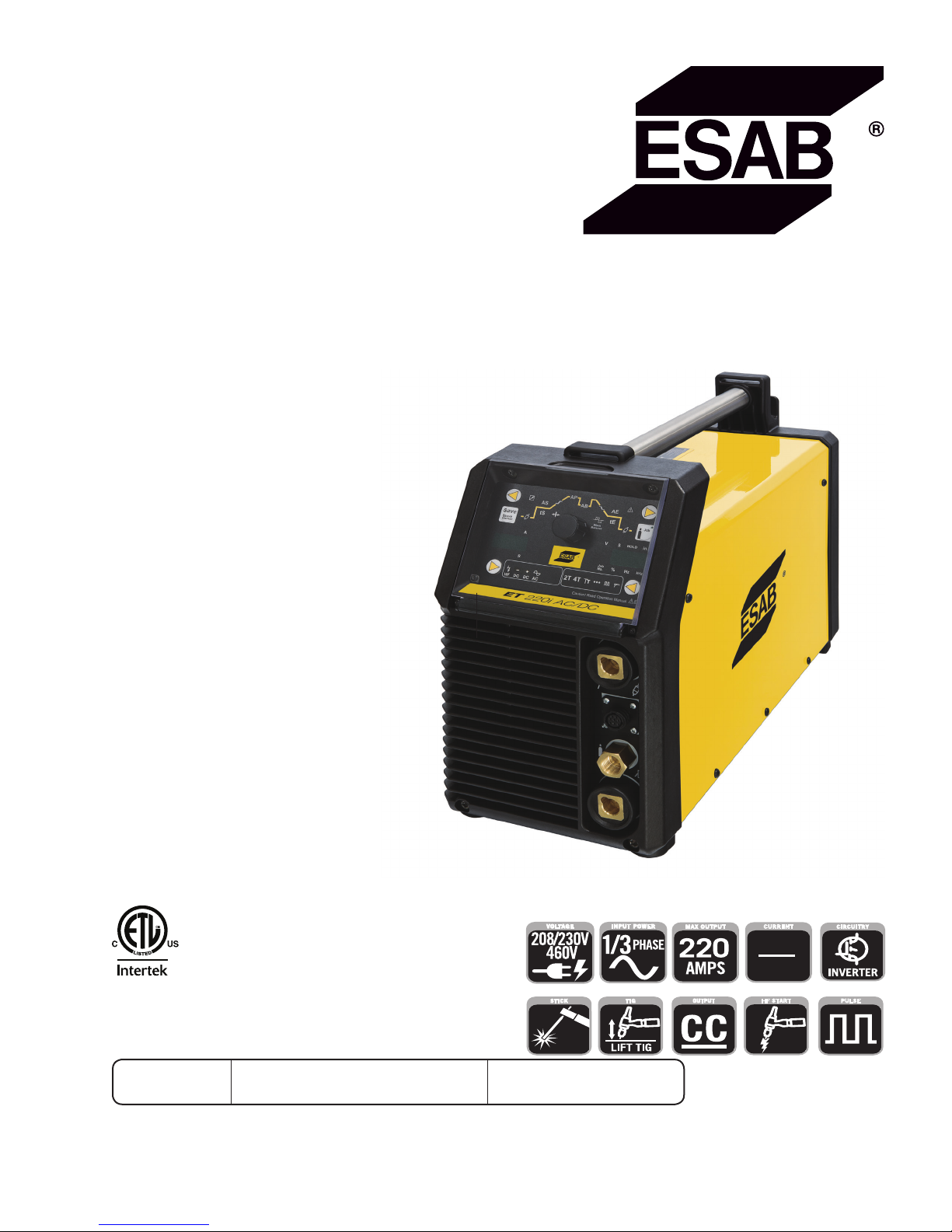
ESAB ET 220i AC/DC
Art # A-12839_AB
4010062
HF START
HF
PULSE
CURRENT
AC
DC
Operating
Manual
Révision : AD Issue Date: October 26, 2016 Manual No.: 0-5346
esab.com
Page 2

WE APPRECIATE YOUR BUSINESS!
Congratulations on your new ESAB product. We are proud to have you as our customer and will
strive to provide you with the best service and reliability in the industry. This product is backed by
our extensive warranty and world-wide service network. To locate your nearest distributor or service
agency, visit us on the web at www.esab.com
This Operating Manual has been designed to instruct you on the correct use and operation of your
ESAB product. Your satisfaction with this product and its safe operation is our ultimate concern.
Therefore please take the time to read the entire manual, especially the Safety Precautions. They
will help you to avoid potential hazards that may exist when working with this product.
YOU ARE IN GOOD COMPANY!
The Brand of Choice for Contractors and Fabricators Worldwide.
ESAB is a Global Brand of Welding Products.
We distinguish ourselves from our competition through market-leading, dependable products that
have stood the test of time. We pride ourselves on technical innovation, competitive prices, excellent delivery, superior customer service and technical support, together with excellence in sales
and marketing expertise.
Above all, we are committed to developing technologically advanced products to achieve a safer
working environment within the welding industry.
Page 3

WARNING
!
Welding Power Supply
Operating Manual Number 0-5346 for:
ESAB ET 220i AC/DC Power Source Part Number W1009300
Published by:
ESAB
2800 Airport Rd.
Denton, Texas 76207
www.esab.com
Copyright © 2015 by
ESAB
Read and understand this entire Manual and your employer’s safety practices before installing, operating, or
servicing the equipment.
While the information contained in this Manual represents the Manufacturer's best judgement, the Manufacturer assumes no liability for its use.
All rights reserved.
Reproduction of this work, in whole or in part, without written permission of the publisher
is prohibited.
The publisher does not assume and hereby disclaims any liability to any party for any loss
or damage caused by any error or omission in this Manual, whether such error results from
negligence, accident, or any other cause.
Publication Date: May 7, 2015
Revision Date: October 26, 2016
Record the following information for Warranty purposes:
Where Purchased: ____________________________________
Purchase Date: ____________________________________
Equipment Serial #: ____________________________________
i
Page 4
Be sure this information reaches the operator.
You can get extra copies through your supplier.
CAUTION
These INSTRUCTIONS are for experienced operators. If you are not fully familiar with
the principles of operation and safe practices for arc welding and cutting equipment,
we urge you to read our booklet, “Precautions and Safe Practices for Arc Welding, Cutting, and Gouging,” Form 0-5407. Do NOT permit untrained persons to install, operate,
or maintain this equipment. Do NOT attempt to install or operate this equipment until
you have read and fully understand these instructions. If you do not fully understand
these instructions, contact your supplier for further information. Be sure to read the
Safety Precautions before installing or operating this equipment.
USER RESPONSIBILITY
This equipment will perform in conformity with the description thereof contained in this manual and accompanying labels and/or inserts when installed, operated, maintained and repaired in accordance with the instructions
provided. This equipment must be checked periodically. Malfunctioning or poorly maintained equipment should
not be used. Parts that are broken, missing, worn, distorted or contaminated should be replaced immediately.
Should such repair or replacement become necessary, the manufacturer recommends that a telephone or written
request for service advice be made to the Authorized Distributor from whom it was purchased.
This equipment or any of its parts should not be altered without the prior written approval of the manufacturer. The
user of this equipment shall have the sole responsibility for any malfunction which results from improper use, faulty
maintenance, damage, improper repair or alteration by anyone other than the manufacturer or a service facility
designated by the manufacturer.
!
READ AND UNDERSTAND THE INSTRUCTION MANUAL BEFORE INSTALLING OR
OPERATING.
PROTECT YOURSELF AND OTHERS!
Page 5

TABLE OF CONTENTS
SECTION 1: SAFETY ........................................................................................ 1-1
1.0 Safety Precautions .......................................................................................... 1-1
SECTION 2:
INTRODUCTION ..................................................................................... 2-1
2.01 How To Use This Manual ................................................................................ 2-1
2.02 Equipment Identification ................................................................................. 2-1
2.03 Receipt of Equipment ...................................................................................... 2-1
2.04 Description ..................................................................................................... 2-1
2.05 User Responsibility ......................................................................................... 2-1
2.06 Transporting Methods ..................................................................................... 2-2
2.07 Packaged Items .............................................................................................. 2-2
2.08 Duty Cycle ....................................................................................................... 2-2
2.09 Specifications ................................................................................................. 2-3
2.10 Optional Accessories ...................................................................................... 2-4
SECTION 3:
INSTALLATION, OPERATION AND SETUP ........................................................ 3-1
3.01 Environment ................................................................................................... 3-1
3.02 Location .......................................................................................................... 3-1
3.03 Ventilation ....................................................................................................... 3-1
3.04 Mains Supply Voltage Requirements .............................................................. 3-1
3.05 High Frequency Introduction .......................................................................... 3-2
3.06 High Frequency Interference ........................................................................... 3-2
3.07 Electromagnetic Compatibility ........................................................................ 3-3
3.08 Power Source Controls, Indicators and Features ............................................ 3-4
3.09 Setup for TIG (GTAW) Welding ..................................................................... 3-10
3.10 TIG (GTAW) Programming Mode ................................................................. 3-13
3.11 TIG (GTAW) Welding Secondary Parameters ............................................... 3-18
3.12 GTAW Spot Welding Mode with DWELL Time (Stitch Mode) ........................ 3-19
3.13 Tip Tronic Operation...................................................................................... 3-20
3.14 Setup for Stick (SMAW) Welding ................................................................ 3-22
3.15 Stick (SMAW) Programming Mode............................................................... 3-23
3.16 User Specific Menus ..................................................................................... 3-26
3.17 Special Function ........................................................................................... 3-27
3.18 Shielding Gas Regulator/ Flowmeter Operating Instructions ......................... 3-30
3.19 Foot Control, Part No. W4013200 (Optional Accessory) .............................. 3-32
SECTION 4:
BASIC WELDING GUIDE ............................................................................ 4-1
4.01 Stick (SMAW) Basic Welding Technique ......................................................... 4-1
4.02 Stick (SMAW) Welding Troubleshooting ......................................................... 4-8
4.03 TIG (GTAW) Basic Welding Technique .......................................................... 4-11
4.04 TIG (GTAW) Welding Problems ..................................................................... 4-13
Page 6

TABLE OF CONTENTS
SECTION 5:
POWER SOURCE PROBLEMS AND ROUTINE SERVICE REQUIREMENTS .................... 5-1
5.01 Basic Troubleshooting .................................................................................... 5-1
5.02 Power Source Problems ................................................................................. 5-3
5.03 Routine Service and Calibration Requirements ............................................... 5-4
5.04 Cleaning the Welding Power Source ............................................................... 5-5
SECTION 6:
KEY SPARE PARTS ................................................................................... 6-1
6.01 Key Spare Parts .............................................................................................. 6-2
APPENDIX A: CIRCUIT DIAGRAM OF ET 220i AC/DC .................................................. A-1
REVISION HISTORY ........................................................................................ A-2
Page 7
ET 220I AC/DC
SECTION 1: SAFETY
1.0 Safety Precautions
Users of ESAB welding and plasma cutting equipment have the ultimate responsibility for ensuring that
anyone who works on or near the equipment observes all the relevant safety precautions. Safety precautions
must meet the requirements that apply to this type of welding or plasma cutting equipment. The following
recommendations should be observed in addition to the standard regulations that apply to the workplace.
All work must be carried out by trained personnel well acquainted with the operation of the welding or plasma
cutting equipment. Incorrect operation of the equipment may lead to hazardous situations which can result in
injury to the operator and damage to the equipment.
1. Anyone who uses welding or plasma cutting equipment must be familiar with:
- its operation
- location of emergency stops
- its function
-
relevant safety precautions
- welding and / or plasma cutting
2. The operator must ensure that:
- no unauthorized person stationed within the working area of the equipment when it is started up.
- no one is unprotected when the arc is struck.
3. The workplace must:
- be suitable for the purpose
- be free from drafts
4. Personal safety equipment:
- Always wear recommended personal safety equipment, such as safety glasses, ame proof
clothing, safety gloves.
- Do not wear loose tting items, such as scarves, bracelets, rings, etc., which could become
trapped or cause burns.
5. General precautions:
- Make sure the return cable is connected securely.
- Work on high voltage equipment may only be carried out by a qualied electrician.
- Appropriate re extinguishing equipment must be clearly marked and close at hand.
- Lubrication and maintenance must not be carried out on the equipment during operation.
Dispose of electronic equipment at the recycling facility!
In observance of European Directive 2002/96/EC on Waste Electrical and Electronic Equipment and its implementation in accordance with national law, electrical and/or electronic equipment that has reached the end of its life must be disposed of at a
recycling facility.
As the person responsible for the equipment, it is your responsibility to obtain information on approved collection stations.
For further information contact the nearest ESAB dealer.
ESAB can provide you with all necessary welding protection and accessories.
Manual 0-5346 SAFETY
1-1
Page 8
ET 220I AC/DC
Arc welding and cutting can be injurious to yourself and others. Take
precautions when welding and cutting. Ask for your employer's safety
WARNING
ELECTRIC SHOCK - Can kill.
- Install and earth (ground) the welding or plasma cutting unit in accordance with applicable standards.
- Do not touch live electrical parts or electrodes with bare skin, wet gloves or wet clothing.
- Insulate yourself from earth and the workpiece.
- Ensure your working stance is safe.
FUMES AND GASES - Can be dangerous to health.
- Keep your head out of the fumes.
- Use ventilation, extraction at the arc, or both, to take fumes and gases away from your breathing zone
and the general area.
ARC R AYS - Can injure eyes and burn skin.
- Protect your eyes and body. Use the correct welding / plasma cutting screen and lter lens and wear
protective clothing.
- Protect bystanders with suitable screens or curtains.
FIRE HAZARD
- Sparks (spatter) can cause re. Make sure therefore that there are no inammable materials nearby.
practices which should be based on manufacturers' hazard data.
NOISE - Excessive noise can damage hearing.
- Protect your ears. Use earmus or other hearing protection.
- Warn bystanders of the risk.
MALFUNCTION - Call for expert assistance in the event of malfunction.
READ AND UNDERSTAND THE INSTRUCTION MANUAL BEFORE INSTALLING OR OPERATING.
PROTECT YOURSELF AND OTHERS!
Do not use the power source for thawing frozen pipes.
WARNING
Class A equipment is not intended for use in residential
CAUTION
locations where the electrical power is provided by the
public low-voltage supply system. There may be potential diculties in ensuring electromagnetic compatibility
of class A equipment in those locations, due to conducted
as well as radiated disturbances.
This product is solely intended for welding. Any other use may result in
CAUTION
CAUTION
SAFETY Manual 0-5346
1-2
personal injury and / or equipment damage.
Read and understand the instruction manual before
installing or operating.
!
Page 9
SECTION 2:
INTRODUCTION
ET 220I AC/DC
2.01 How To Use This Manual
To ensure safe operation, read the entire manual, including the
chapter on safety instructions and warnings.
Throughout this manual, the words WARNING,
CAUTION, and NOTE may appear. Pay particular attention to the
information provided under these headings. These special annotations are easily recognized as follows:
NOTE!
An operation, procedure, or background
information which requires additional
emphasis or is helpful in efficient operation
of the system.
CAUTION
!
A procedure which, if not properly followed,
may cause damage to the equipment.
WARNING
!
A procedure which, if not properly followed,
may cause injury to the operator or others
in the operating area.
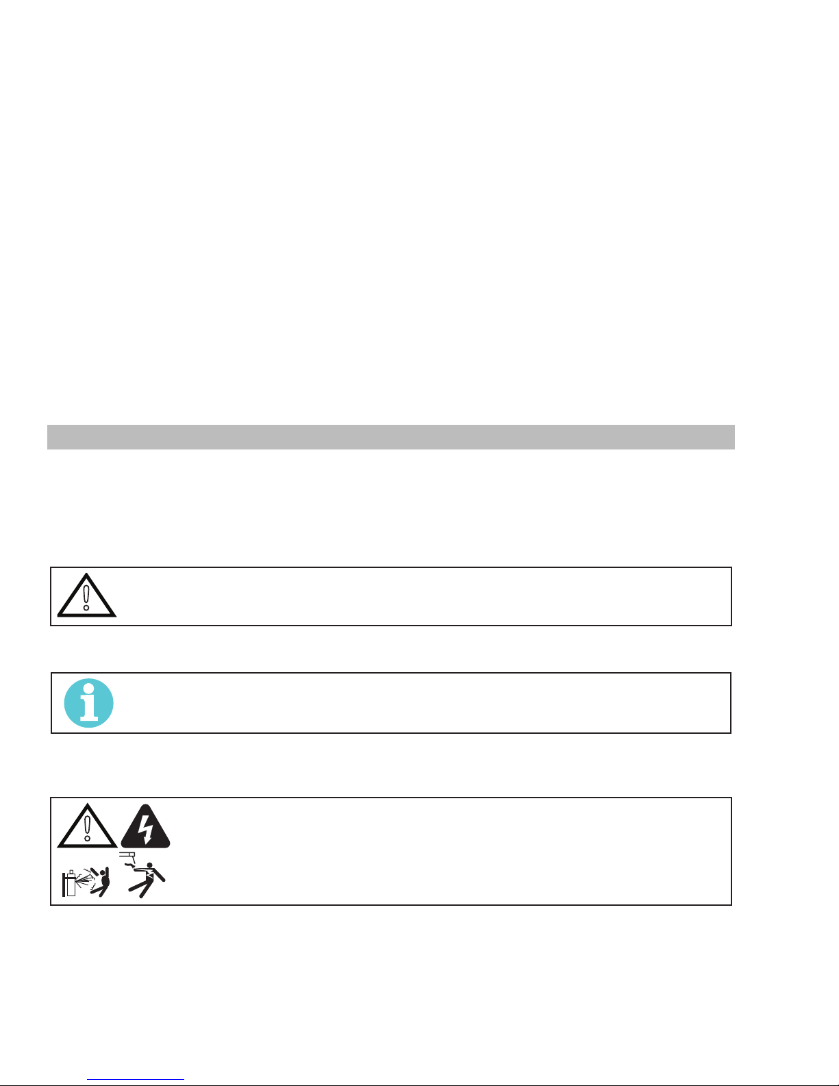
WARNING
Gives information regarding possible electrical shock injury. Warnings will be enclosed
in a box such as this.
You will also notice other icons appearing throughout the manual.
These are to advise you of specific types of hazards or cautions
related to the portion of information that follows. Some may have
multiple hazards that apply and would look something like this:
!
2.03 Receipt of Equipment
When you receive the equipment, check it against the invoice to
make sure it is complete and inspect the equipment for possible damage due to shipping. If there is any damage, notify the
carrier immediately to file a claim. Furnish complete information
concerning damage claims or shipping errors to the location in
your area listed in the inside back cover of this manual.
Include all equipment identification numbers as described above
along with a full description of the parts in error.
Move the equipment to the installation site before un-crating
the unit. Use care to avoid damaging the equipment when using
bars, hammers, etc., to un-crate the unit.
2.04 Description
The ET 220i AC/DC is light weight constant current welding
power sources incorporating the latest digital inverter technology to provide exceptional AC/DC arc characteristics, TIG welding
features include torch trigger latch, pre & post flow gas control,
pulse control, spot weld control, hot start control, up & down
slope control. Liftarc TIG and HF TIG operating modes are available.
This unit also has outstanding arc characteristics across a wide
range of Manual Metal Arc Welding (SMAW) electrodes. SMAW
welding features, hot start control and arc force control. The units
are equipped with digital amperage and voltage meters. The unit
are also fully compliant to European Standard EN 60974-1 and
IEC 60974.1.
The ET 220i AC/DC provide excellent welding performance
across a broad range of applications when used with the correct
welding consumables and procedures. The following instructions
detail how to correctly and safely set up the machine and give
guidelines on gaining the best efficiency and quality from the
Power Source. Please read these instructions thoroughly before
using the unit.
2.02 Equipment Identification
The unit’s identification number (specification or part number),
model, and serial number usually appear on a nameplate attached to the control panel. In some cases, the nameplate may
be attached to the rear panel. Equipment which does not have
a control panel such as gun and cable assemblies is identified
only by the specification or part number printed on the shipping
container. Record these numbers on the bottom of page ii for
future reference.
Manual 0-5346 INTRODUCTION
2.05 User Responsibility
This equipment will perform as per the information contained
herein when installed, operated, maintained and repaired in
accordance with the instructions provided. This equipment must
be checked periodically. Defective equipment (including welding
leads) should not be used. Parts that are broken, missing, plainly
worn, distorted or contaminated, should be replaced immediately.
Should such repairs or replacements become necessary, it is
recommended that such repairs be carried out by appropriately
qualified persons approved by ESAB. Advice in this regard can be
obtained by contacting an Accredited ESAB Distributor.
This equipment or any of its parts should not be altered from
standard specification without prior written approval of ESAB.
The user of this equipment shall have the sole responsibility for
any malfunction which results from improper use or unauthorized
modification from standard specification, faulty maintenance,
damage or improper repair by anyone other than appropriately
qualified persons approved by ESAB.
2-1
Page 10
ET 220I AC/DC
!
2.06 Transporting Methods
WARNING
2.07 Packaged Items
ET 220i AC/DC Inverter Power Source (Part No. W1009300)
• ET 220i AC/DC Inverter Power Source
• Two male 50mm Dinse connectors
• Operating Manual
2.08 Duty Cycle
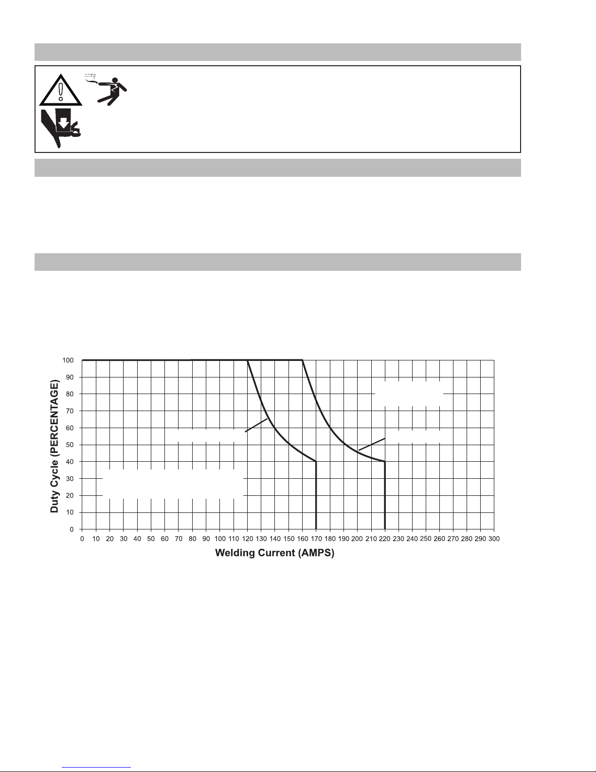
The rated duty cycle of a Welding Power Source, is a statement of the time it may be operated at its rated welding current output without exceeding the temperature limits of the insulation of the component parts. To explain the 10 minute duty cycle period the following example is used. Suppose a Welding Power Source is designed to operate at a 40% duty cycle, 170 amperes at 26.8 volts. This
means that it has been designed and built to provide the rated amperage (170A) for 4 minutes, i.e. arc welding time, out of every 10
minute period (40% of 10 minutes is 4 minutes). During the other 6 minutes of the 10 minute period the Welding Power Source must
idle and be allowed to cool. The thermal cut out will operate if the duty cycle is exceeded.
Disconnect input power conductors from de-energized supply line before moving the welding
Power Source.
Lift Power Source with handle on top of case. Use handcart or similar device of adequate capacity. If using a fork lift vehicle, secure the Power Source on a proper skid before transporting.
SMAW (STICK)
SAFE OPERATING REGION
(TIG & STICK)
Figure 2-1: ET 220i AC/DC Duty Cycle
ET 220i AC/DC
GTAW (TIG)
Art # A-12840
INTRODUCTION Manual 0-5346
2-2
Page 11

ET 220I AC/DC
2.09 Specifications
Description ET 220i AC/DC
Power Source Part Number W1009300
Power Source Mass 29.5lbs (13.4Kg) without power cable
Power Source Dimensions H13" x W7.25" x D19"
(H326mm x W185mm x D483mm)
Cooling Fan Cooled
Welder Type Inverter Power Source
Standards CSA E60974-1, ANSI/IEC 60974-1
Number of Phases 1/3 phase
Nominal Supply Voltage 208-230/460VAC (1 phase)
+/-15%
Nominal Supply Frequency 50/60Hz
Welding Current Range (Stick Mode) 10 – 150A (1 phase) 10 – 170A (3 phase)
Welding Current Range (TIG Mode) 5 - 200A (1 phase) 5 - 220A (3 phase)
Effective Input Current (I1eff) (note2) 27.6A (208V, 1 phase)
25.0A (230V, 1 phase)
15.2A (460V, 1 phase)
Maximum Input Current (I1max) 37.3A (208V, 1 phase)
33.7A (230V, 1 phase)
18.1A (460V, 1 phase)
Generator Requirement (note4) 13kW (16kVA @ 0.8PF)
Stick (SMAW)
Welding Output, 40ºC, 10 min.
TIG (GTAW)
Welding Output, 40ºC, 10 min.
Open Circuit Voltage (VRD active) <113V
Protection Class IP23S
150A @ 40%, 26.0V (1 phase)
140A @ 60%, 25.6V (1 phase)
120A @ 100%, 24.8V (1 phase)
200A@45%, 18.8V (1 phase)
180A@60%, 17.2V (1 phase)
160A@100%, 16.4V (1 phase)
Table 2-1: Power Source Specification
208-230/460VAC (3 phase)
+/-15%
16.8A (208V, 3 phase)
15.2A (230V, 3 phase)
8.2A (460V, 3 phase)
24.5A (208V, 3 phase)
22.1A (230V, 3 phase)
11.9A (460V, 3 phase)
170A @ 40%, 26.8V (3 phase)
140A @ 60%, 25.6V (3 phase)
120A @ 100%, 24.8V (3 phase)
220A @ 40%, 18.8V (3 phase)
180A @ 60%, 17.2V (3 phase)
160A @ 100%, 16.4V (3 phase)
Manual 0-5346 INTRODUCTION
2-3
Page 12
ET 220I AC/DC
NOTE!
Note 1:Due to variations that can occur in manufactured products, claimed performance, voltages, ratings,
all capacities, measurements, dimensions and weights quoted are approximate only. Achievable capacities
and ratings in use and operation will depend upon correct installation, use, applications, maintenance and
service.
Note 2: The Effective Input Current should be used for the determination of cable size & supply requirements.
Note 3: Motor start fuses or thermal circuit breakers are recommended for this application. Check local
requirements for your situation in this regard.
Note 4: Generator Requirements at the Maximum Output Duty Cycle.
Due to large variations in performance and specifications of different brands and types of generators, ESAB
cannot guarantee full welding output power or duty cycle on every brand or type of generator.
ESAB recommends that when selecting a generator, that the particular power source / generator combination be adequately trialled to ensure the combination performs to the users expectations.
Note 5: ESAB reserves the right to change product performance and specifications without notice.
2.10 Optional Accessories
Part Number Description
W4014604 Tig Torch 26F with 4m lead and remote control
BGSAK2 TIG Torch accessory kit
W4013200 Foot Control with 8m lead
646757 Electrode Holder & Work Lead Set 5m 400A 50mm DINSE
646325 Electrode Holder & Work Lead Set 8m 400A 50mm DINSE
646763 Electrode Holder w / Deadman Switch & Work Lead Set 8m 400A 50mm DINSE
301526 Comet Edge Argon Regulator / Flowmeter
704461 50mm Male DINSE cable connector
W7004913 Shielding Gas Hose Assembly
W4001302 CU-6 (400V) Water Cooling Unit
W4001350 Cable Protection (CU-6)
W4010205 Cart, 2 Wheel
Table 2-2: Options and Accessories
INTRODUCTION Manual 0-5346
2-4
Page 13
SECTION 3:
!
!
INSTALLATION, OPERATION AND SETUP
ET 220I AC/DC
3.01 Environment
These units are designed for use in environments with increased
hazard of electric shock as outlined in IEC 60974-1.
A. Examples of environments with increased hazard of electric
shock are:
1. In locations in which freedom of movement is restricted,
so that the operator is forced to perform the work in a
cramped (kneeling, sitting or lying) position with physical contact with conductive parts.
2. In locations which are fully or partially limited by conductive elements, and in which there is a high risk of
unavoidable or accidental contact by the operator.
3. In wet or damp hot locations where humidity or perspiration considerable reduces the skin resistance of the
human body and the insulation properties of accessories.
B. Environments with increased hazard of electric shock do
not include places where electrically conductive parts in
the near vicinity of the operator, which can cause increased
hazard, have been insulated.
3.02 Location
Be sure to locate the welder according to the following guidelines:
A. In areas, free from moisture and dust.
B. Ambient temperature between 0° C to 40° C.
C. In areas, free from oil, steam and corrosive gases.
D. In areas, not subjected to abnormal vibration or shock.
3.03 Ventilation
WARNING
Since the inhalation of welding
fumes can be harmful, ensure
that the welding area is effectively ventilated.
3.04 Mains Supply Voltage
Requirements
The Mains supply voltage should be within ± 15% of the rated
mains supply voltage. Too low a voltage may cause poor welding
performance. Too high a supply voltage will cause components to
overheat and possibly fail.
The Welding Power Source must be:
• Correctly installed, if necessary, by a qualified electrician.
• Correctly earthed (electrically) in accordance with local
regulations.
• Connected to the correct size power point and fuse as per
the Specifications on page 2-5.
WARNING
Any electrical work must be carried out by
a qualified Electrical Tradesperson.
WARNING
ELECTRIC SHOCK can kill; SIGNIFICANT DC
VOLTAGE is present after removal of input
power.
E. In areas, not exposed to direct sunlight or rain.
F. Place at a distance of 12" (300mm) or more from walls or
similar that could restrict natural air flow for cooling.
G. The enclosure design of this power source meets the
requirements of IP23S as outlined in EN 60529. This provides
adequate protection against solid objects (greater than 1/2",
12mm), and direct protection from vertical drops. Under no circumstances should the unit be operated or connected in a micro
environment that will exceed the stated conditions. For further
information please refer to EN 60529.
H. Precautions must be taken against the power source top-
pling over. The power source must be located on a suitable
horizontal surface in the upright position when in use.
WARNING
DO NOT TOUCH live electrical parts.
SHUT DOWN welding power source, disconnect input power employing lockout/tagging procedures. Lockout/tagging procedures
consist of padlocking line disconnect switch in open position,
removing fuses from fuse box, or shutting off and red-tagging
circuit breaker or other disconnecting device.
Electrical Input Requirements
Operate the welding power source from a single or three-phase
50/60 Hz, AC power supply. The input voltage must match one of
the electrical input voltages shown on the input data label on the
unit nameplate. Contact the local electric utility for information
about the type of electrical service available, how proper connections should be made, and inspection required. The line disconnect switch provides a safe and convenient means to completely
remove all electrical power from the welding power supply
whenever necessary to inspect or service the unit.
This equipment should be electrically
Manual 0-5346 INSTALLATION, OPERATION AND SETUP
connected by a qualified electrician.
3-1
Page 14
ET 220I AC/DC
Art # A-12451
!
NOTE!
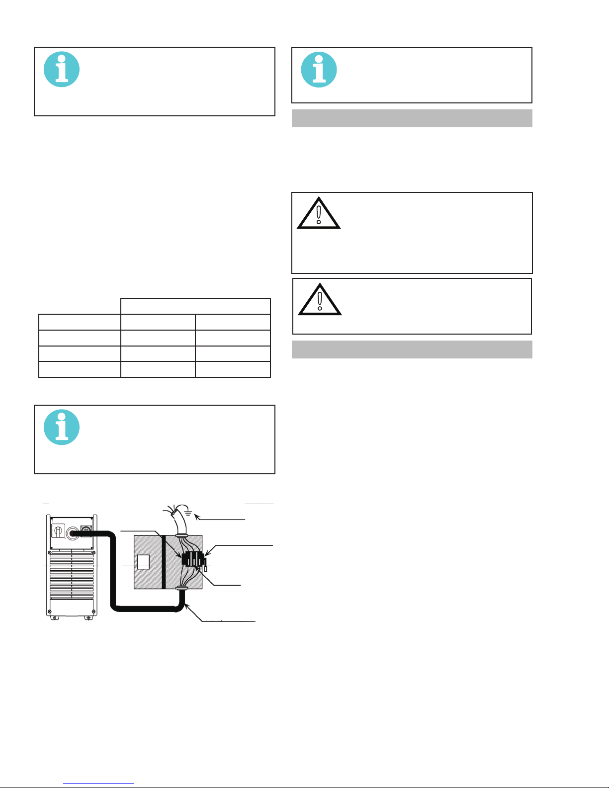
This unit is equipped with a three-conductor with earth power cable that is connected at the welding power source end for
single or three-phase electrical input power.
Do not connect an input (WHITE, BLACK or RED) conductor to the
ground terminal.
Do not connect the ground (GREEN) conductor to an input line
terminal.
Refer to Figure 3-1 and:
1. Connect end of ground (GREEN) conductor to a suitable
ground. Use a grounding method that complies with all
applicable electrical codes.
2. For 3- phase operation, connect ends of line 1 (BLACK)
and line 2 (WHITE) and line 3 (RED) input conductors to
a de-energized line disconnect switch.
For 1- phase operation, connect BLACK and WHITE input
conductors. Insulate the RED Conductor.
3. Use Table 3-1 as a guide to select line fuses for the
disconnect switch.
Fuse Size
Input Voltage 1 Phase 3 Phase
208 VAC 100 Amps 60 Amps
230 VAC 80 Amps 50 Amps
460 VAC 50 Amps 30 Amps
Table 3-1 Electrical Input Connections
NOTE!
Fuse size is based on not more than 200
percent of the rated input amperage of the
welding power source (Based on Article
630, National Electrical Code).
Welding Power Source
Ground Terminal
Ground Conductor
Line Disconnect Switch
Line Fuse
Primary Power Cable
NOTE!
Note the available input power. Damage to
the PCB could occur if 575VAC or higher is
applied.
3.05 High Frequency Introduction
The importance of correct installation of high frequency welding
equipment cannot be overemphasized. Interference due to high
frequency initiated or stabilized arc is almost invariably traced to
improper installation. The following information is intended as a
guide for personnel installing high frequency welding machines.
WARNING EXPLOSIVES
The high frequency section of this machine
has an output similar to a radio transmitter.
The machine should NOT be used in the
vicinity of blasting operations due to the
danger of premature firing.
WARNING COMPUTER
!
It is also possible that operation close to
computer installations may cause computer malfunction.
3.06 High Frequency Interference
Interference may be transmitted by a high frequency initiated or
stabilized arc welding machine in the following ways.
1. Direct Radiation: Radiation from the machine can oc-
cur if the case is metal and is not properly grounded. It can occur
through apertures such as open access panels. The shielding of
the high frequency unit in the Power Source will prevent direct
radiation if the equipment is properly grounded.
2. Transmission via the Supply Lead: Without adequate
shielding and filtering, high frequency energy may be fed to the
wiring within the installation (mains) by direct coupling. The
energy is then transmitted by both radiation and conduction.
Adequate shielding and filtering is provided in the Power Source.
3. Radiation from Welding Leads: Radiated interference
from welding leads, although pronounced in the vicinity of the
leads, diminishes rapidly with distance. Keeping leads as short
as possible will minimise this type of interference. Looping and
suspending of leads should be avoided wherever possible.
4. Re-Radiation from Unearthed Metallic Objects: A
major factor contributing to interference is re-radiation from
unearthed metallic objects close to the welding leads. Effective
grounding of such objects will prevent re-radiation in most cases.
Figure 3-1 Electrical Input Connections
Input Power
Each unit incorporates an INRUSH circuit and input voltage
sensing circuit. When the MAIN SWITCH is turned ON, the inrush
circuit provides a pre-charging of the input capacitors. A relay in
the Main Power PCB2 will turn on after the input capacitors have
charged to operating voltage (after approximately 5 seconds).
INSTALLATION, OPERATION AND SETUP Manual 0-5346
3-2
Page 15
ET 220I AC/DC
3.07 Electromagnetic Compatibility
WARNING
Extra precautions for Electromagnetic
Compatibility may be required when this
Welding Power Source is used in a domestic situation.
A. Installation and Use - Users Responsibility
The user is responsible for installing and using the welding
equipment according to the manufacturer’s instructions. If
electromagnetic disturbances are detected then it shall be
the responsibility of the user of the welding equipment to
resolve the situation with the technical assistance of the
manufacturer. In some cases this remedial action may be
as simple as earthing the welding circuit, see NOTE below.
In other cases it could involve constructing an electromagnetic screen enclosing the Welding Power Source and the
work, complete with associated input filters. In all cases,
electromagnetic disturbances shall be reduced to the point
where they are no longer troublesome.
NOTE!
The welding circuit may or may not be
earthed for safety reasons. Changing the
earthing arrangements should only be
authorised by a person who is competent to
assess whether the changes will increase
the risk of injury, e.g. by allowing parallel
welding current return paths which may
damage the earth circuits of other equipment. Further guidance is given in IEC
60974-13 Arc Welding Equipment - Installation and use (under preparation).
B. Assessment of Area
Before installing welding equipment, the user shall make
an assessment of potential electromagnetic problems in the
surrounding area. The following shall be taken into account
1. Other supply cables, control cables, signalling and telephone cables; above, below and adjacent to the welding
equipment.
2. Radio and television transmitters and receivers.
3. Computer and other control equipment.
4. Safety critical equipment, e.g. guarding of industrial
equipment.
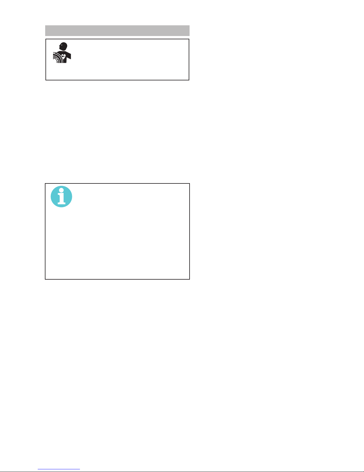
5. The health of people around, e.g. the use of pacemakers
and hearing aids.
6. Equipment used for calibration and measurement.
7. The time of day that welding or other activities are to be
carried out.
8. The immunity of other equipment in the environment:
the user shall ensure that other equipment being used
in the environment is compatible: this may require additional protection measures.
The size of the surrounding area to be considered will
depend on the structure of the building and other activities
Manual 0-5346 INSTALLATION, OPERATION AND SETUP
that are taking place. The surrounding area may extend
beyond the boundaries of the premises.
C. Methods of Reducing Electromagnetic Emissions
1. Mains Supply
Welding equipment should be connected to the mains
supply according to the manufacturer’s recommendations. If interference occurs, it may be necessary to take
additional precautions such as filtering of the mains
supply. Consideration should be given to shielding the
supply cable of permanently installed welding equipment in metallic conduit or equivalent. Shielding should
be electrically continuous throughout its length. The
shielding should be connected to the Welding Power
Source so that good electrical contact is maintained
between the conduit and the Welding Power Source
enclosure.
2. Maintenance of Welding Equipment
The welding equipment should be routinely maintained
according to the manufacturer’s recommendations. All
access and service doors and covers should be closed
and properly fastened when the welding equipment is in
operation. The welding equipment should not be modified in any way except for those changes and adjustments covered in the manufacturer’s instructions. In
particular, the spark gaps of arc striking and stabilising
devices should be adjusted and maintained according to
the manufacturer’s recommendations.
3. Welding Cables
The welding cables should be kept as short as possible
and should be positioned close together, running at or
close to the floor level.
4. Equipotential Bonding
Bonding of all metallic components in the welding in-
stallation and adjacent to it should be considered. However. Metallic components bonded to the work piece will
increase the risk that the operator could receive a shock
by touching the metallic components and the electrode
at the same time. The operator should be insulated from
all such bonded metallic components.
5. Grounding of the Workpiece
Where the workpiece is not bonded to earth for electri-
cal safety, nor connected to earth groundbecause of it’s
size and position, e.g. ship’s hull or building steelwork,
a connection bonding the workpiece to earth ground
may reduce emissions in some, but not all instances.
Care should be taken to prevent the grounding of the
workpiece increasing the risk of injury to users, or damage to other electrical equipment. Where necessary, the
connection of the workpiece to earth should be made
by direct connection to the workpiece, but in some
countries where direct connection is not permitted, the
bonding should be achieved by suitable capacitance,
selected according to national regulations.
6. Screening and Shielding
Selective screening and shielding of other cables
and equipment in the surrounding area may alleviate
problems of interference. Screening the entire welding
installation may be considered for special applications.
3-3
Page 16
ET 220I AC/DC
3.08 Power Source Controls, Indicators and Features
4T2T
T
Art # A-12841
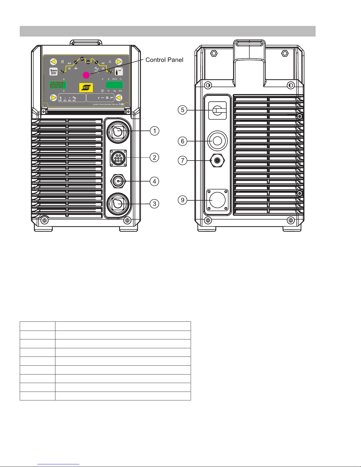
Figure 3-2: Controls on Front and Rear Panel
1. Electrode Welding Terminal
Electrode Welding Terminal. Welding current flows from the Power Source via 50mm Dinse type terminals. It is essential, however,
that the male plug is inserted and turned securely to achieve a sound electrical connection.
2. 8 Pin Control Socket
The 8 pin receptacle is used to connect a trigger switch or remote control to the welding Power Source circuitry:
To make connections, align keyway, insert plug, and rotate threaded collar fully clockwise. The socket information is included in the
event the supplied cable is not suitable and it is necessary to wire a plug or cable to interface with the 8 pin receptacle.
Socket Pin Part Number / Description
1 Not used
2 Trigger Switch Input
3 Trigger Switch Input
4 Not used
5 Remote Control Potentiometers Maximum
6 Remote Control Potentiometers Minimum
7 Remote Control Potentiometer Wiper
8 Not used
Table 3-1: 8 Pin Interconnection Control Plug Configuration Figure 3-3: 8 Pin Control Socket
3. Worklead Welding Terminal
Worklead Welding Terminal. Welding current flows from the Power Source via 50mm Dinse type terminals. It is essential, however,
that the male plug is inserted and turned securely to achieve a sound electrical connection.
INSTALLATION, OPERATION AND SETUP Manual 0-5346
3-4
Page 17
ET 220I AC/DC
!
CAUTION
!
4. Shielding Gas Outlet
The Shielding Gas Outlet located on the front panel is a 5/8"-18 UNF female gas fitting and is utilized for the connection of a suitable
TIG Torch.
5. Power On/Off Switch
This Switch is located on the rear of the Power Source and turns mains power off and on.
!
6. Mains Supply Lead
The ET 220i AC/DC is fitted with a heavy duty mains supply lead, 10ft long cable, no plug.
7. Gas Inlet
The Shielding Gas Inlet connection is used to supply the appropriate shielding gas to the unit. The gas inlet is located on the rear of
the Power Source. It is 5/8"-18 UNF female inert gas connection.
Loose welding terminal connections can cause overheating and result in the male plug being fused in the
terminal.
WARNING
When the front digital displays are lit, the machine is connected to the Mains supply voltage and the internal electrical components are at Mains voltage potential.
WARNING
Only Inert Shielding Gases specifically designed for welding applications should be used.
9. Remote Control Socket (Automation)
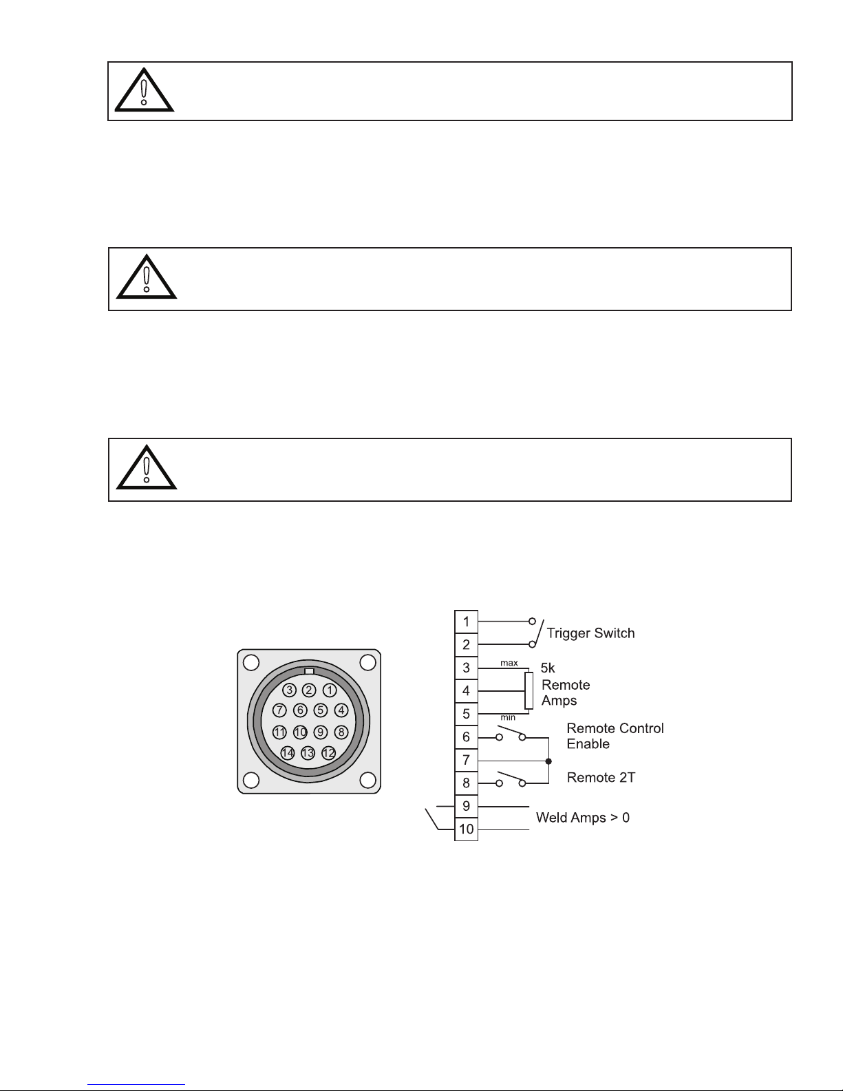
The 14 pin Automation Remote Control Socket is used to connect remote control devices to the welding power source.
To make connections, align keyway, insert plug, and rotate threaded collar fully clockwise.
The Automation Remote Control Socket is located on the rear of the Power Source.
A-12034
Manual 0-5346 INSTALLATION, OPERATION AND SETUP
Figure 3-4: 14 Pin Remote Control Socket
3-5
Page 18
ET 220I AC/DC
Socket Pin Part Number / Description
1 Trigger Switch Input
2 Trigger Switch Input
3 Remote Control 5k ohm Potentiometers Maximum
4 Remote Control 5k ohm Potentiometers Wiper
5 Remote Control 5k ohm Potentiometers Minimum
6 Remote Control Enable (Short to common to enable remote control)
7 Common
8 Remote 2T (short to common to select remote control active in 2T operation mode only)
9 Volt free relay contact, Weld Amps > 0A
10 Volt free relay contact, Weld Amps > 0A
11 Not used
12 Not used
13 Not used
14 Not used
Table 3-2: 14 Pin Interconnection Control Plug Configuration
A-12055
4T2T
T
Art # A-12842
Figure 3-5: Control Panel Weld Mode & Meter Displays
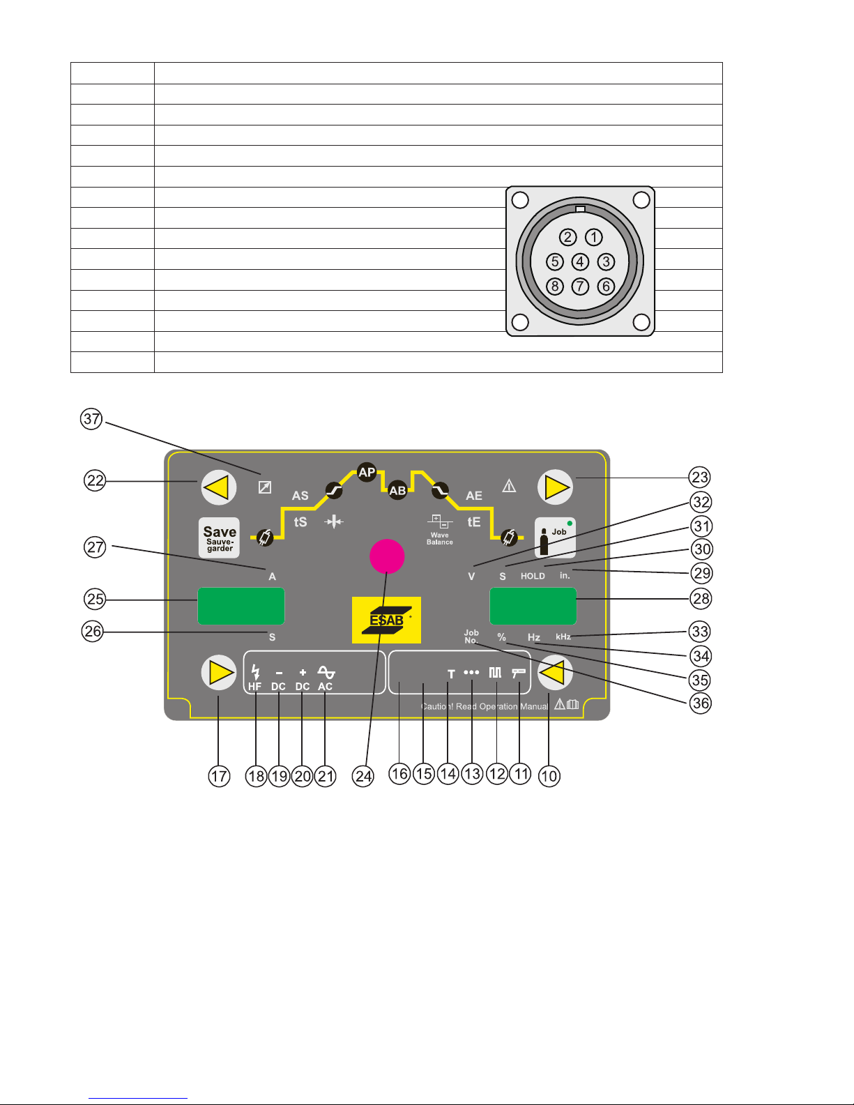
10. Welding Mode Button
Press the MODE button to select the Welding Process mode. Available modes are GTAW 2T, GTAW 4T, GTAW Spot, GTAW Pulse 2T,
GTAW Pulse 4T, TIPTRONIC, TT and SMAW.
11. SMAW indicator light
This light will illuminate when the power source is in SMAW welding mode.
12. Pulse indicator light
This light will illuminate when the power source is in GTAW Pulse 2T or 4T welding mode.
INSTALLATION, OPERATION AND SETUP Manual 0-5346
3-6
Page 19

ET 220I AC/DC
13. Spot indicator light
This light will illuminate when the power source is in GTAW SPOT welding mode.
14. Tiptronic indicator light (Refer to Section 3.12)
This light will illuminate when the power source is in TIPTRONIC welding mode and a saved job has been loaded.
15 4T (latch) indicator light
This light will illuminate when the power source is in GTAW 4T welding mode.
This mode of welding is mainly used for long welding runs to reduce operator fatigue. In this mode the operator can press and release
the torch trigger and the output will remain active. To deactivate the power source, the trigger switch must again be depressed and
released, thus eliminating the need for the operator to hold the torch trigger.
Note that when operating in GTAW (TIG mode), the power source will remain activated until the selected downslope time has elapsed.
16. 2T (normal) indicator light
This light will illuminate when the power source is in GTAW 2T welding mode.
In this mode, the torch trigger must remain depressed for the welding output to be active. Press and hold the torch trigger to activate
the power source (weld). Release the torch trigger switch to cease welding.
17. Welding Type Button
Press the TYPE button to select the Welding Type mode, i.e. current mode. Selects the welding current type DC, AC with/without HF
ignition.
In SMAW (Stick) mode, the available modes are Electrode DC-, Electrode DC+.
In GTAW (Tig) mode, the available modes are Electrode DC-, HF Electrode DC-, AC and HF AC.
18. HF (high frequency) indicator light
This light will illuminate when the power source is in GTAW 2T or 4T HF welding mode.
19. Electrode Negative indicator light
This light will illuminate when the power source is in Electrode Negative welding mode on the top welding terminal. (DC Output)
20. Electrode Positive indicator light
This light will illuminate when the power source is in Electrode Positive welding mode on the top welding terminal. (DC Output)
21. Electrode AC indicator light (only for AC/DC)
This light will illuminate when the power source is in Electrode AC welding mode on the top welding terminal. (AC Output)
22. BACK Welding Parameter Button
Press the BACK welding parameter button to scroll left through the available welding parameters.
23. FORWARD Welding Parameter Button
Press the FORWARD welding parameter button to scroll right through the available welding parameters.
24. Multi Function Control
Turn the MULTI FUNCTION CONTROL to adjust the available welding parameters.
When not welding, the Multi Function Control is used to adjust all welding parameters, including welding amps. A short press on the
Scroll Left or Scroll Right button will save the welding parameter value, then increment / decrement to the next available welding
parameter. The welding parameter LED will illuminate and the Multi Function Control will then adjust the selected welding parameter.
The parameter code and parameter value are shown on the meters and the LED's next to the meter indicate if the parameter is Amps,
Seconds, Inches, %, kHz or Hz.
During welding, adjustment of the Multi Function Control will adjust the selected parameter.
Manual 0-5346 INSTALLATION, OPERATION AND SETUP
3-7
Page 20

ET 220I AC/DC
25. Digital Ammeter / Parameter Codes
The digital amperage meter is used to display both the pre-set current and actual output current of the power source. It is also used
to display Welding Parameter Codes.
Depending on the Welding Parameter selected, the status indictor adjacent to the ammeter will illuminate to show the units of the
welding parameter.
When welding, the amperage meter will display actual welding current.
At the completion of welding, the amperage meter will hold the last recorded amperage value for a period of approximately 10 seconds. The amperage meter will hold the value until; (1) any of the front panel controls are adjusted in which case the unit will revert to
preview mode, (2) welding is recommenced, in which case actual welding amperage will be displayed, or (3) a period of 10 seconds
elapses following the completion of welding in which case the unit will return to preview mode.
26. Seconds indicator light
This light will illuminate when Seconds are being shown on the Digital Ammeter Display.
27. Amps indicator light
This light will illuminate when Amps are being shown on the Digital Ammeter Display.
28. Digital Voltmeter / Parameter meter
The digital volt meter is used to display the actual output voltage of the power source. It is also used to display Welding Parameters.
Depending on the Programming Parameter selected, the status indictor adjacent to the volt meter will illuminate to show the units
of the welding parameter.
When welding, the volt meter will display actual welding voltage.
At the completion of welding, the volt meter will hold the last recorded voltage value for a period of approximately 10 seconds. The
volt meter will hold the value until; (1) any of the front panel controls are adjusted, (2) welding is recommenced, or (3) a period of 10
seconds elapses following the completion of welding.
29. Inch indicator light
This light will illuminate when "Inches (")" are being shown on the Digital Volt meter Display for electrode diameter size.
30. HOLD indicator light
This light will illuminate when the HOLD function is active on the Digital Display at the completion of welding.
31. Seconds indicator light
This light will illuminate when Seconds are being shown on the Digital Volt meter Display.
32. Volts indicator light
This light will illuminate when Volts are being shown on the Digital Volt meter Display.
33. kHz (frequency) indicator light
This light will illuminate when kHz (frequency) is being shown on the Digital Volt meter Display.
34. Hz (frequency) indicator light
This light will illuminate when Hz (frequency) is being shown on the Digital Volt meter Display.
35. % (percentage) indicator light
This light will illuminate when % (percentage) is being shown on the Digital Volt meter Display.
36. Job Number indicator light
This light will illuminate when Job Number is being shown on the Digital Volt meter Display.
37. Remote Control indicator light
This light will illuminate when the Remote Control is active.
INSTALLATION, OPERATION AND SETUP Manual 0-5346
3-8
Page 21
4T2T
Art # A-12843
T
Figure 3-6: Control Panel
ET 220I AC/DC
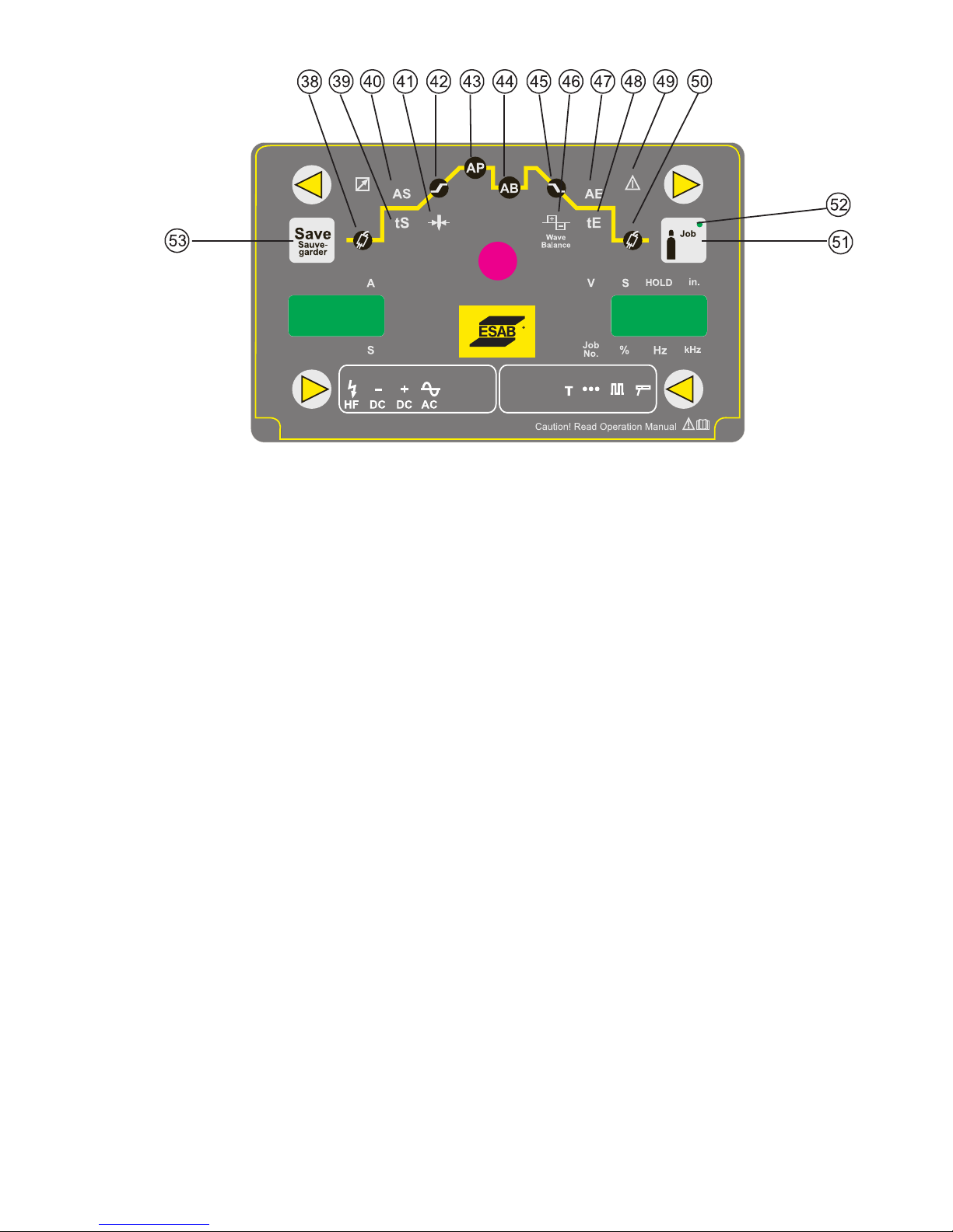
38. Pre Flow indicator light
This light will illuminate when the Pre Flow Welding Parameter is selected.
39. Initial Current time (GTAW) and Hot Start time (SMAW) indicator light
This light will illuminate when the Initial Current Time Welding Parameter is selected in GTAW mode, or when Hot Start Time Welding
Parameter is selected in SMAW mode.
40. Initial Current amps (GTAW) and Hot Start amps (SMAW) indicator light
This light will illuminate when the Initial Current Amps Welding Parameter is selected in GTAW mode, or when Hot Start Amps Welding
Parameter is selected in SMAW mode.
41. Electrode Diameter indicator light
This light will illuminate when the Electrode Diameter Welding Parameter is selected.
42. Up Slope indicator light
This light will illuminate when the Up Slope Welding Parameter is selected.
43. Peak Current light
This light will illuminate when the Peak Current Welding Parameter is selected.
44. Background Current indicator light
This light will illuminate when the Background Current Welding Parameter is selected.
45. Down Slope indicator light
This light will illuminate when the Down Slope Welding Parameter is selected.
46. AC Balance indicator light
This light will illuminate when the AC Balance Welding Parameter is selected.
47. Crater Current indicator light
This light will illuminate when the Crater Current Welding Parameter is selected.
Manual 0-5346 INSTALLATION, OPERATION AND SETUP
3-9
Page 22
ET 220I AC/DC
!
48. Crater Current time indicator light
This light will illuminate when the Crater Current Time Welding Parameter is selected.
49. Electrode Diameter Out-of-Range indicator light
This light will illuminate when the set welding current is outside the normal operating range for the selected Electrode Diameter.
50. Post Flow indicator light
This light will illuminate when the Post Flow Welding Parameter is selected.
51. Gas Purge Button
Press the button once to active that gas valve and then press it again to turn it off, also if you press and release this button the gas
will purge for 30 seconds and then turn off.
52. Tip Tronic indicator light (Refer to Section 3.13)
This light will illuminate when an active TipTronic job is selected.
53. Save Tip Tronic Job Button
Press the SAVE button to save the current TipTronic Job settings in the selected memory location
Up to 100 jobs can be saved arranged as 10 banks of 10 jobs.
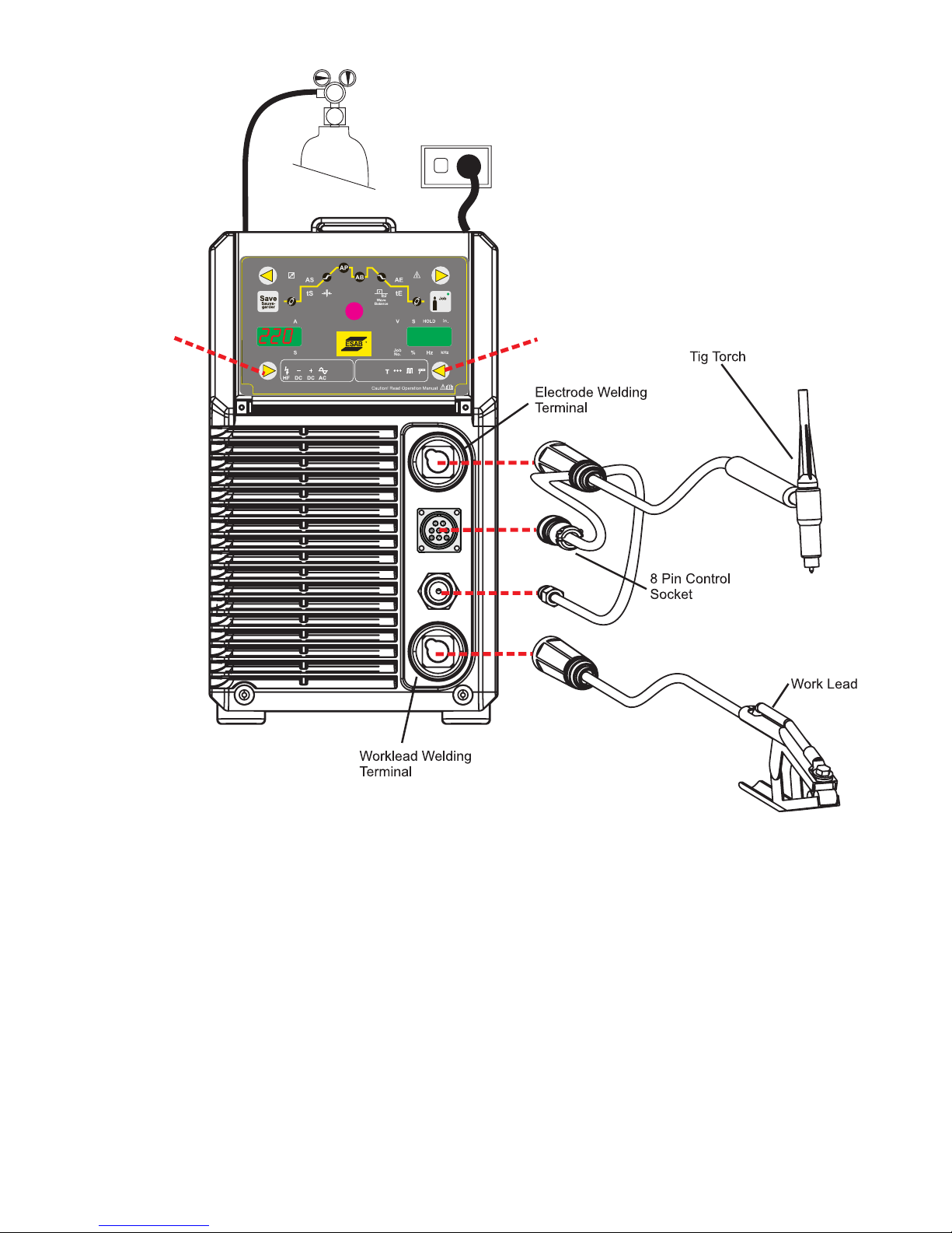
3.09 Setup for TIG (GTAW) Welding
A. Select a GTAW operation mode with the welding mode & welding type buttons (refer to Section 3.10 for further information).
B. Connect the TIG Torch to the Electrode welding terminal (top). Welding current flows from the power source via Dinse type
terminals. It is essential, however, that the male plug is inserted and turned securely to achieve a sound electrical connection.
C. Connect the work lead to the Worklead welding terminal (bottom). Welding current flows from the Power Source via Dinse type
terminals. It is essential, however, that the male plug is inserted and turned securely to achieve a sound electrical connection.
CAUTION
!
D. Connect the TIG torch trigger switch via the 8 pin socket located on the front of the power source as shown below. The TIG
torch will require a trigger switch to operate in Liftarc TIG or HF TIG Mode.
E. Fit the welding grade shielding gas regulator/flowmeter to the shielding gas cylinder (refer to Section 3.19) then connect the
shielding gas hose from the regulator/flowmeter outlet gas INLET on the rear of the Power Source. Connect the gas hose from
the TIG torch to the gas OUTLET on the front of the Power Source.
Loose welding terminal connections can cause overheating and result in the male plug being fused in the
Dinse terminal.
NOTE!
If the TIG torch has a remote TIG torch current control fitted then it will require to be connected to the 8 pin
socket. (Refer to section 3.08 Remote Control Socket for further information).
WARNING
Before connecting the work clamp to the work make sure the mains power supply is switched off.
Secure the welding grade shielding gas cylinder in an upright position by chaining it to a suitable
INSTALLATION, OPERATION AND SETUP Manual 0-5346
3-10
stationary support to prevent falling or tipping.
Page 23
ET 220I AC/DC
17
10
4T2T
T
Art # A-12844
Figure 3-7: Setup for TIG Welding
Manual 0-5346 INSTALLATION, OPERATION AND SETUP
3-11
Page 24
ET 220I AC/DC
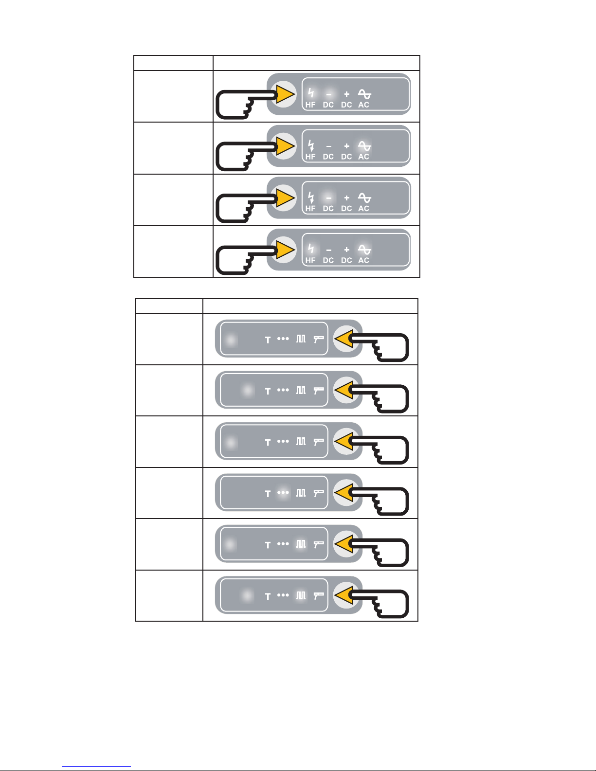
• First, select a Welding Type by pressing the Weld Type (17) button.
Welding Type Welding Type Selection
DC HF TIG
AC Liftarc TIG
DC Liftarc TIG
AC HF TIG
• Then, select a Welding Mode by pressing the WELDING MODE (10) button.
Welding Mode Welding Mode Selection
2T (Normal
Mode)
4T (Latch Mode)
Tip Tronic
(used to recall
saved jobs)
Spot Mode
2T Pulse Welding
(Normal Mode)
4T Pulse Welding
(Latch Mode)
2T
2T
2T
2T
2T
2T
4T
4T
4T
4T
4T
4T
T
T
T
T
T
T
INSTALLATION, OPERATION AND SETUP Manual 0-5346
3-12
Page 25
3.10 TIG (GTAW) Programming Mode
ET 220I AC/DC
4T2T
T
Art # A-12845
Figure 3-8: TIG Programming Mode
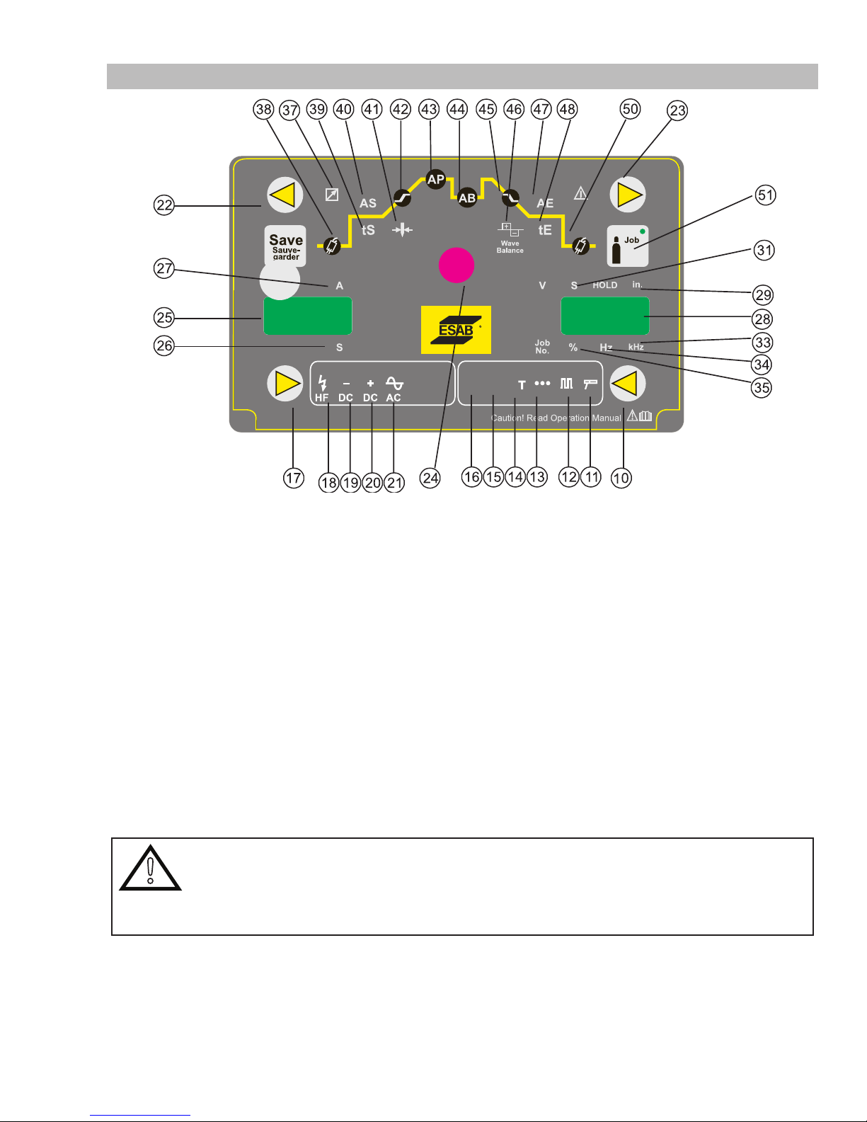
• Press the WELDING MODE (10) button to select the appropriate GTAW mode.
Several GTAW operating modes are available.
2T (normal mode). The 2T LED (16) will illuminate.
4T (latch mode). The 4T LED (15) will illuminate.
Tiptronic. The TIPTRONIC LED (14) will illuminate
SPOT mode. The SPOT LED (13) will illuminate.
2T PULSE (normal mode). The 2T LED (16) and PULSE LED (12) will illuminate.
4T PULSE (latch mode). The 4T LED (15) and PULSE LED (12) will illuminate.
• Press the WELDING TYPE (17) button to select the welding output type
Several GTAW operating modes are available.
AC welding output mode. The AC LED (21) will illuminate.
DC Negative welding output mode. The DC Negative LED (19) will illuminate.
HF AC welding output mode. The HF LED (18) and the AC LED (21) will illuminate.
HF DC Negative welding output mode. The HF LED (18) and the DC Negative LED (19) will illuminate.
WARNING
!
In HF operating mode, high voltage pulses are generated within the power source, to provide contactless
initiation of the GTAW welding arc. If HF operating mode is selected, high voltage will be present on the
tungsten electrode when the trigger is pressed. Never touch the tungsten welding electrode of any parts in
the welding circuit when the trigger is pressed..
• Press the BACK button (22) or FORWARD button (23) so the Electrode Diameter LED (41) and Inches LED (29) are illuminated.
Use the Multi Function Control (24) to adjust the Electrode size being used.
• Press the BACK button (22) or FORWARD button (23) until the Peak Current LED (43) is illuminated.
Use the Multi Function Control (24) to adjust the Welding Current for the Electrode size being used. If the Welding Current does
not match the normal operating range of the electrode the Electrode Diameter Out-of-Range indictor LED (49) will illuminate.
If the Electrode Diameter Out-of-Range indictor LED (49) is illuminated, it is still possible to weld.
Manual 0-5346 INSTALLATION, OPERATION AND SETUP
3-13
Page 26
ET 220I AC/DC
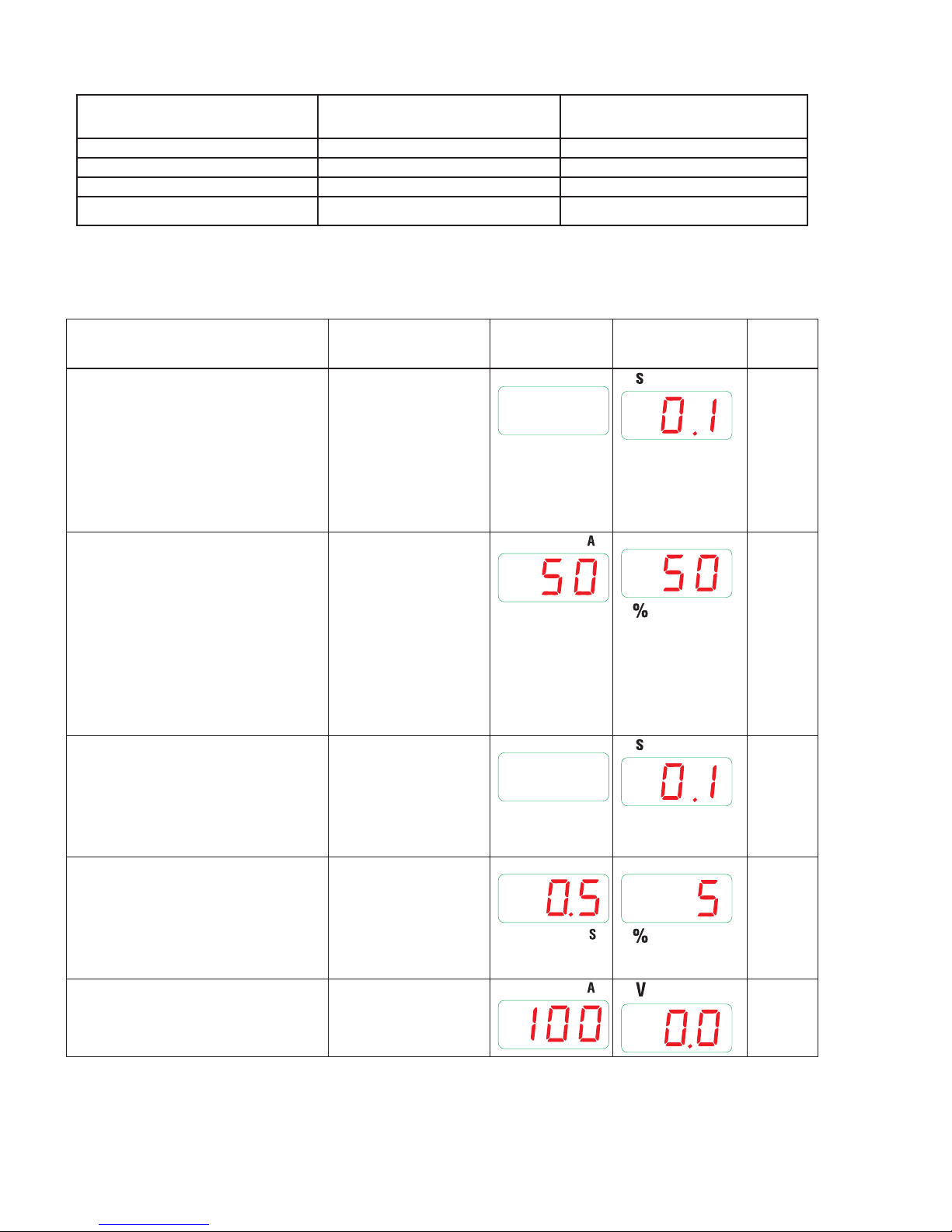
Note that other parameters may need to be set, according to the operating mode selected, Please refer to the tables below.
GTAW Electrode Diameter
Nominal Welding Current (A) DC Nominal Welding Current (A) AC
(inches)
0.040" (1.0mm)
1/16" (1.6mm)
3/32" (2.4mm)
1/8" (3.2mm)
Table 3-3: Normal Welding Current for GTAW Electrode size
5 - 40 Amps 5 - 30 Amps
15 - 130 Amps 20 - 90 Amps
70 - 240 Amps 70 - 180 Amps
140 - 320 Amps 130 - 250 Amps
Note that Normal recommended Welding Current AC Amps are dependent on the type of electrode and on the AC
Balance Parameter setting.
Parameter Range LED Code
(Left Display)
Parameter Value
(Right Display)
Factory
Setting
Shielding Gas Pre-Flow time
This parameter operates in GTAW
0.1-10.0 seconds 0.1
modes only and is used to provide
gas to the weld zone prior to striking
the arc, once the torch trigger switch
has been pressed. This control is
used to dramatically reduce weld
porosity at the start of a weld.
Start Current AS
This parameter operates in GTAW
modes only and is used to set the
start current for TIG. In 4T mode the
Initial Current remains on until the
torch trigger switch is released after
it has been depressed. In 2T mode
the Initial Current remains on for the
5 – 200% of Welding
Current A1
The maximum
welding current
in GTAW mode is
limited to 220A for
the ET 220i AC/DC.
50
When A1=100A
Start Current Time tS and then the Up
Slope current ramp will commence.
Start Current Time tS
(2T normal mode only)
This parameter operates in 2T GTAW
0 - 20 seconds
0.1
modes only and set the time the Start
Current is active, after which the Up
Slope current ramp will commence.
Up Slope Time
This parameter operates in GTAW
0 - 99% 5
modes only and is used to set the
time for the weld current to ramp
up from Initial current to welding
current.
Welding Current A1
ET 220i AC/DC 3 - 220 A 100
INSTALLATION, OPERATION AND SETUP Manual 0-5346
3-14
Page 27
ET 220I AC/DC
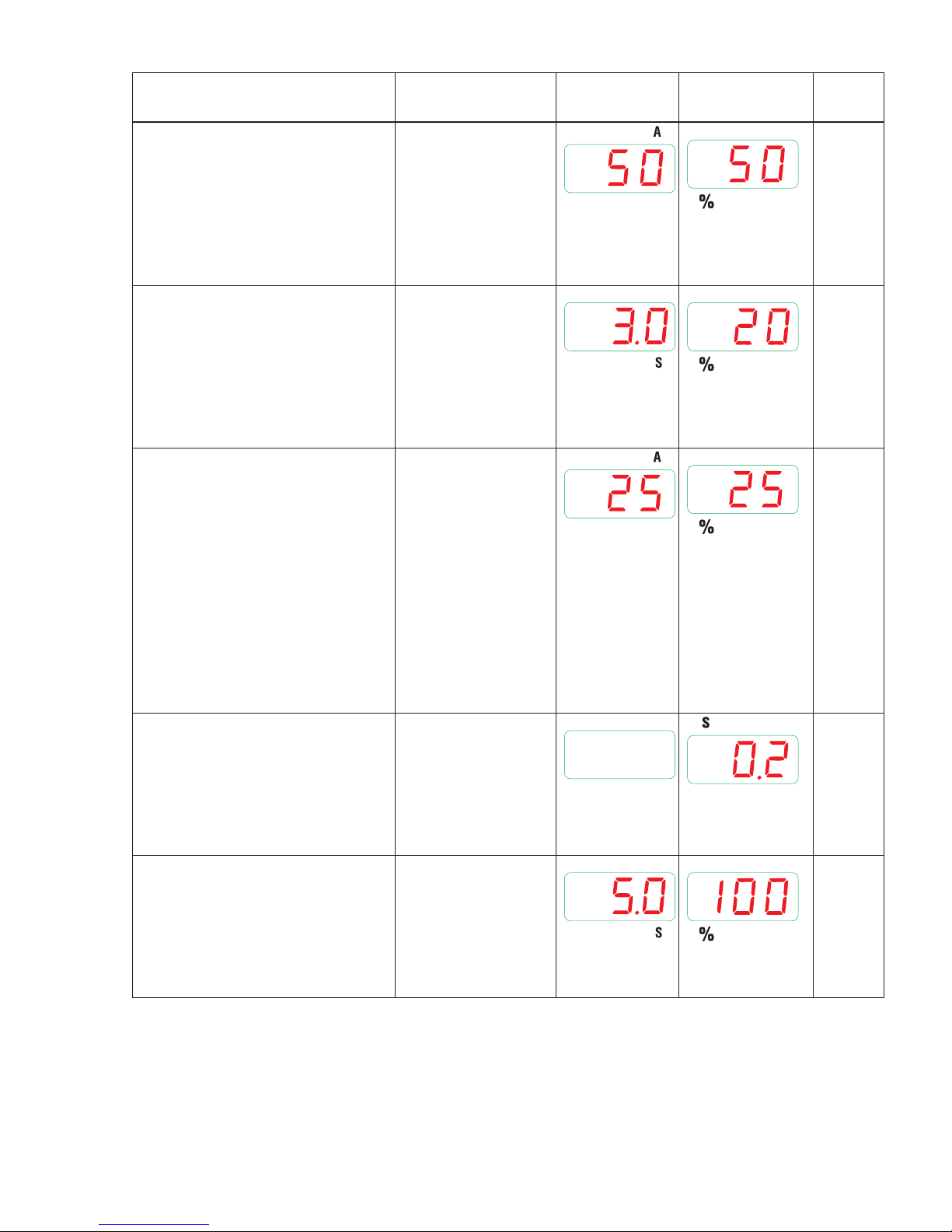
Parameter Range LED Code
Back Ground Current
This parameter operates in GTAW
Pulse modes only and sets the
GTAW Back Ground Current. The
lowest point in the pulse is called the
Trough.
Down Slope Time
This parameter operates in GTAW
modes only and is used to set the
time for the weld current to ramp
down to the crater current. This
control is used to eliminate the crater
that can form at the completion of a
weld.
Crater Current AE
This parameter operates in GTAW
modes only.
This is the current at the end of
the down slope current ramp. The
welding current will remain at
the Crater Current value until the
Crater Current Time has elapsed, at
which time the welding current will
cease and the unit will enter Post
Flow mode. This control is used to
eliminate the crater that can form at
the completion of a weld.
Crater Current Time tE
This parameter operates in GTAW
modes only and is used to set the time
for the crater current before entering
post flow mode. This control is used
to eliminate the crater that can form
at the completion of a weld.
Shielding Gas Post-Flow time
This parameter operates in GTAW
modes only and is used to adjust the
post gas flow time once the arc has
extinguished. This control is used to
dramatically reduce oxidation of the
tungsten electrode.
1 – 200% of Welding
(Left Display)
Parameter Value
(Right Display)
Factory
Setting
50
Current A1
The maximum
welding current
in GTAW mode is
limited to 220A for
the ET 220i AC/DC.
0 – 99% 20
5 – 200% of Welding
25
Current A1
The maximum
welding current
in GTAW mode is
limited to 220A for
the ET 220i AC/DC.
0 – 20 seconds 0.2
20 – 500%
100
Manual 0-5346 INSTALLATION, OPERATION AND SETUP
3-15
Page 28
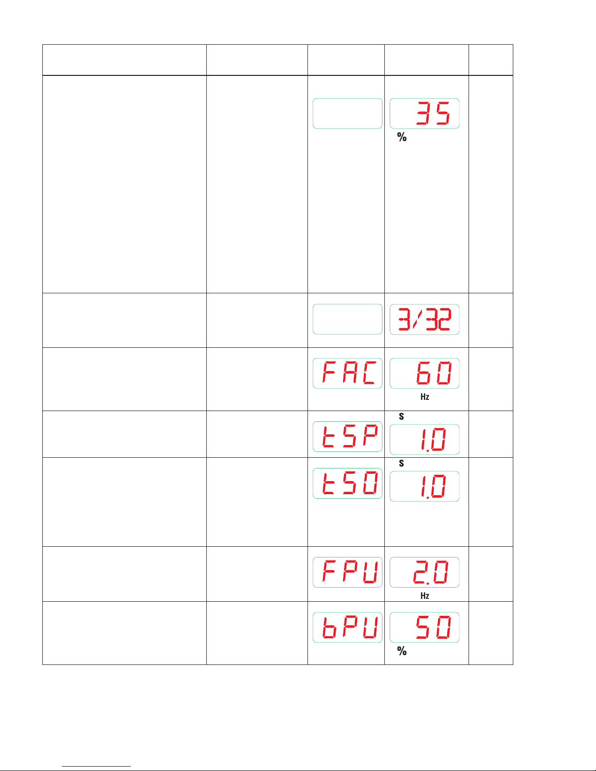
ET 220I AC/DC
Inch
Parameter Range LED Code
AC balance
(AC Output Mode only)
This parameter operates in AC
GTAW modes and is used to set the
penetration to cleaning action ratio
for the AC weld current. Generally
WAVE BALANCE is set to 50%
for AC Stick welding. The WAVE
BALANCE control changes the ratio
of penetration to cleaning action of
the AC TIG welding arc. Maximum
weld penetration is achieved when
the WAVE BALANCE control is set to
10%. Maximum cleaning of heavily
oxidised aluminium or magnesium
alloys is achieved when the WAVE
BALANCE control is set to 65%.
Electrode Diameter
ET 220i AC/DC
Set this parameter to the tungsten
electrode size being used.
AC frequency
This parameter operates in AC mode
only and is used to set the frequency
for the AC weld current
10 – 90% positive
(Left Display)
Parameter Value
(Right Display)
Factory
Setting
35
welding current
.040" – 1/8"
3/32"
30 – 200Hz 60
Spot Welding Time
This parameter sets the spot welding
time
Spot Welding Dwell Time
(only available with Spot Welding
Dwell Time enabled, refer to
secondary parameters)
This parameter sets the dwell (off)
time between repeated spot welds
(Refer to Section 3.12).
Pulse Frequency
This parameter sets the Pulse
Frequency when in GTAW Pulse
operating mode.
Pulse Balance
This parameter sets the percentage
“on” time of the Pulse Frequency for
welding weld current when in Pulse
operating mode
0.01 – 10.0 seconds 1.0
0.09 – 60.0 seconds 1.0
0.2 – 2000Hz 2
1 – 99% of Welding
50
Current A1
Table 3-4: GTAW Main Parameters
INSTALLATION, OPERATION AND SETUP Manual 0-5346
3-16
Page 29
ET 220I AC/DC
A-12057
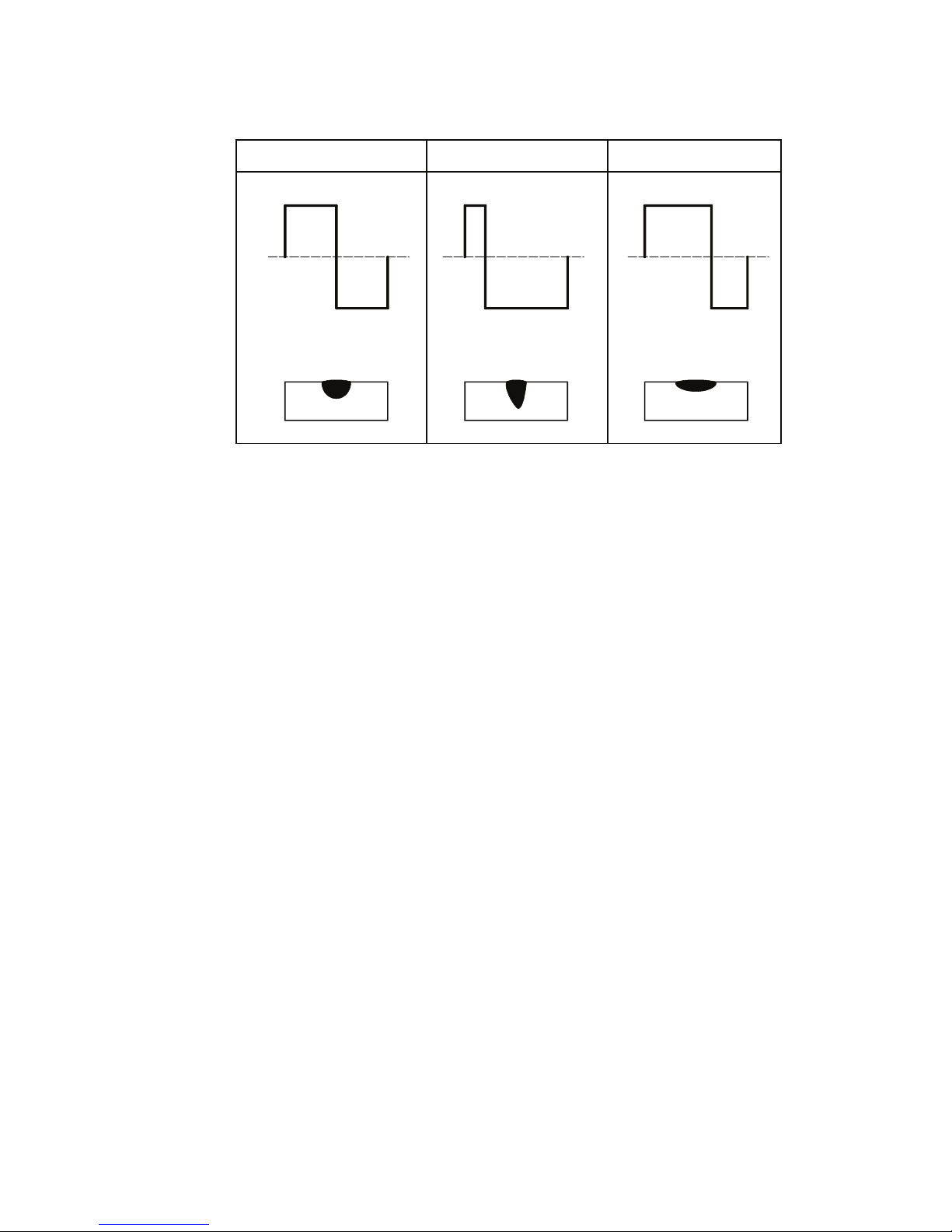
AC BALANCE is used for aluminium welding in AC HF GTAW or AC LIFT GTAW operating modes.
It is used to set the ratio of penetration to cleaning action for the AC GTAW welding arc.
Maximum weld penetration is achieved when the AC BALANCE is set to 10%. Maximum cleaning of heavily oxidized aluminium or
magnesium alloys is achieved when the WAVE BALANCE is set to 90%.
AC Balance = 50% AC Balance = 10% AC Balance = 65%
10%50% 65%
(+)(+) (+)
(-)(-) (-)
90%50% 35%
Balanced with 50% penetration
and 50% cleaning
Maximum Penetration and
reduced cleaning
Table 3-5: AC GTAW Wave Balance
Maximum Cleaning and
reduced penetration
Manual 0-5346 INSTALLATION, OPERATION AND SETUP
3-17
Page 30
ET 220I AC/DC
3.11 TIG (GTAW) Welding Secondary Parameters
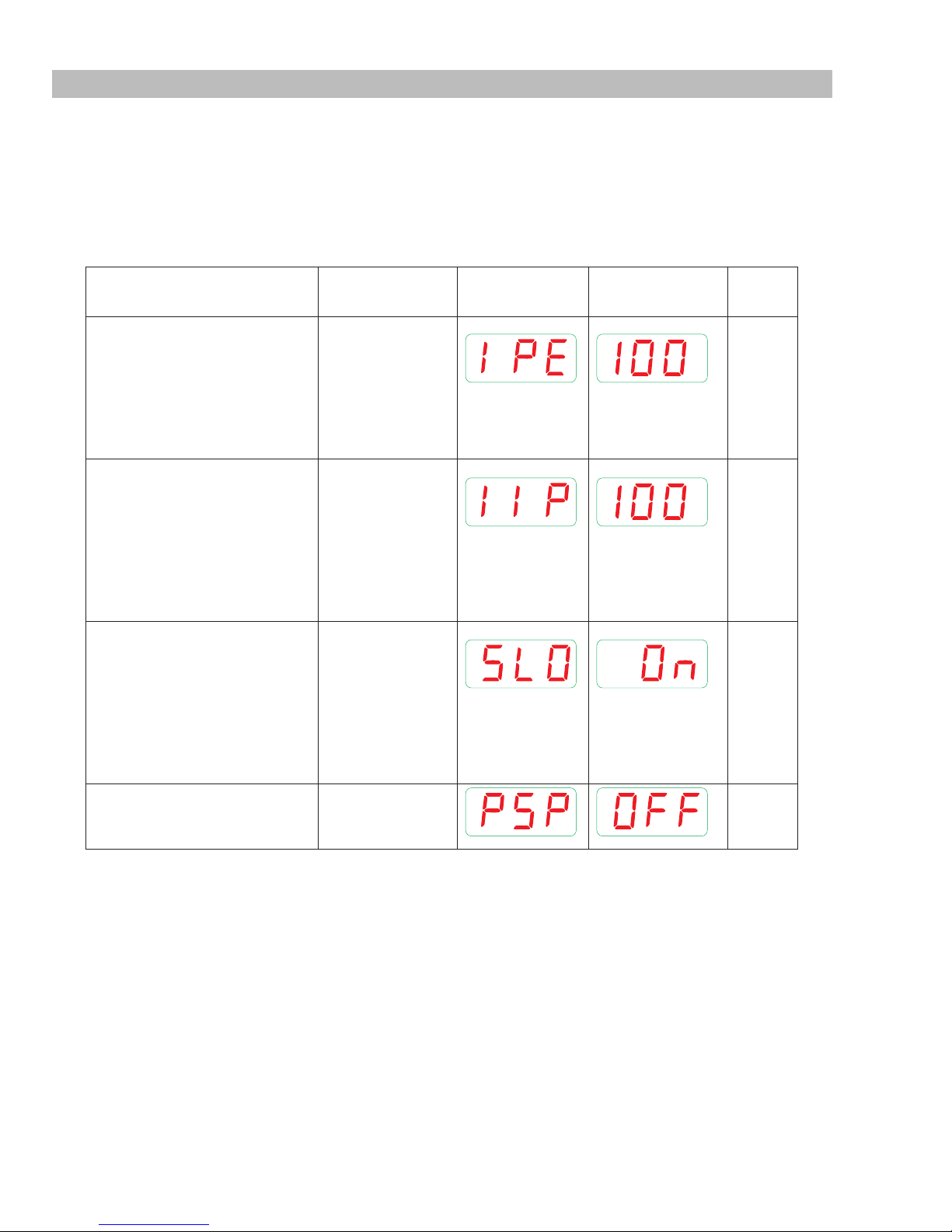
Secondary parameters are available. These are required to be set separately.
• Press and hold the WELDING MODE (10) button then press the SAVE (54) button.
• Press the BACK button (22) or FORWARD button (23) to select the Parameter.
• Use the Multi Function Control (24) to adjust the parameter.
• Press the Welding Mode button to exit this mode.
• Note that some parameters are only available in certain welding modes.
Note that even during welding, these settings can be adjusted and changed.
Parameter Range LED Code
Parameter Value
Factory
Ignition Peak Correction
The ignition peak current is
set after ignition to provide
stabilisation of the arc. A
different peak current is saved
for each selected tungsten
electrode diameter.
Plus terminal Correction
Ignition using the positive
welding terminal is used for
optimum dome formation in
AC GTAW welding. A different
plus terminal current is saved
for each selected tungsten
electrode diameter.
Slope On / Off
The up slope and down slope
can be disabled. When this
feature is set to OFF, current
increase, current decrease,
initial current and crater current
are not available in the main
parameters.
Spot Welding Dwell Time
(enable / disable)
(refer main parameters)
(Left Display)
(Right Display)
Setting
10-200% 100
10 – 200 % 100
ON
ON
OFF
ON
OFF
OFF
Table 3-6: GTAW Secondary Parameters
INSTALLATION, OPERATION AND SETUP Manual 0-5346
3-18
Page 31
ET 220I AC/DC
3.12 GTAW Spot Welding Mode with DWELL Time (Stitch Mode)
4T2T
T
Art # A-12846
Figure 3-9: GTAW Spot Welding Mode with DWELL Time
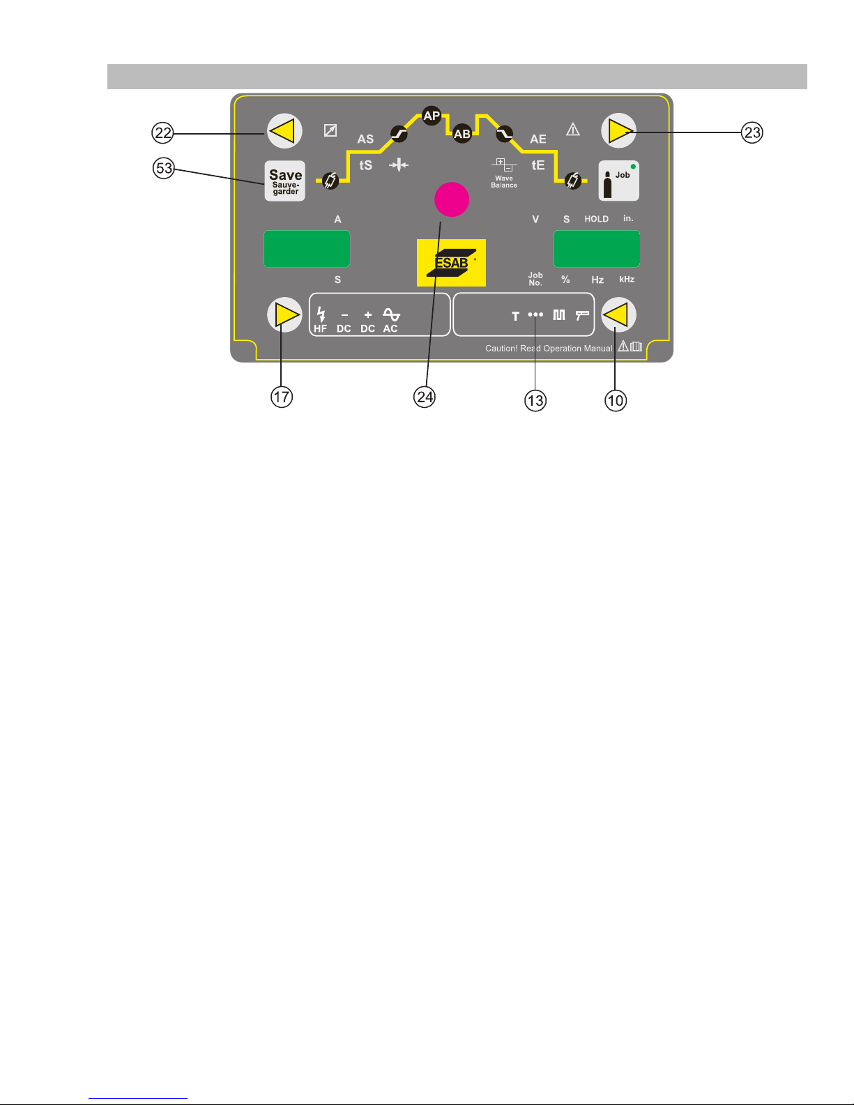
To enable Spot Welding with Dwell Time (Stitch welding) the parameter “PSP” needs to be set to ON (refer secondary parameters) it is
possible to have automated spot welds with this Stitch function.
In 2T mode, the stitch welds are repeated for as long as the trigger is held in.
In 4T mode, press and release the trigger to start the stitch welds, press and release the trigger to end the stitch welds
The parameters tSP and tSO determine the spot time length and the dwell (off) time length
• Press the WELDING MODE (10) button to select GTAW SPOT mode. SPOT mode. The SPOT LED (13) will illuminate.
• Press the WELDING TYPE (17) button to select the welding output type
• Press the BACK button (22) or FORWARD button (23) so the Electrode Diameter LED (41) and inch LED (29) are illuminated.
Use the Multi Function Control (24) to adjust the Electrode size being used.
• Press and hold the WELDING MODE (10) button then press the SAVE (53) button.
• Press the BACK button (22) or FORWARD button (23) to select the “PSP” Parameter.
• Use the Multi Function Control (24) to set “PSP” to ON (to enable stitch welding
• Press the BACK button (22) or FORWARD button (23) until the Peak Current LED (43) is illuminated.
Use the Multi Function Control (24) to adjust the Welding Current for the Electrode size being used. If the Welding Current does not
match the normal operating range of the electrode the Electrode Diameter Out-of-Range indictor LED (49) will illuminate.
• Press the BACK button (22) or FORWARD button (23) until the left display shows “tSP”.
• Use the Multi Function Control (24) to set the required SPOT “ON” time required.
• Press the BACK button (22) or FORWARD button (23) until the left display shows “tSO”.
• Use the Multi Function Control (24) to set the required SPOT “DWELL or OFF” time required.
If the Electrode Diameter Out-of-Range indictor LED (49) is illuminated, it is still possible to weld.
Manual 0-5346 INSTALLATION, OPERATION AND SETUP
3-19
Page 32
ET 220I AC/DC
3.13 Tip Tronic Operation
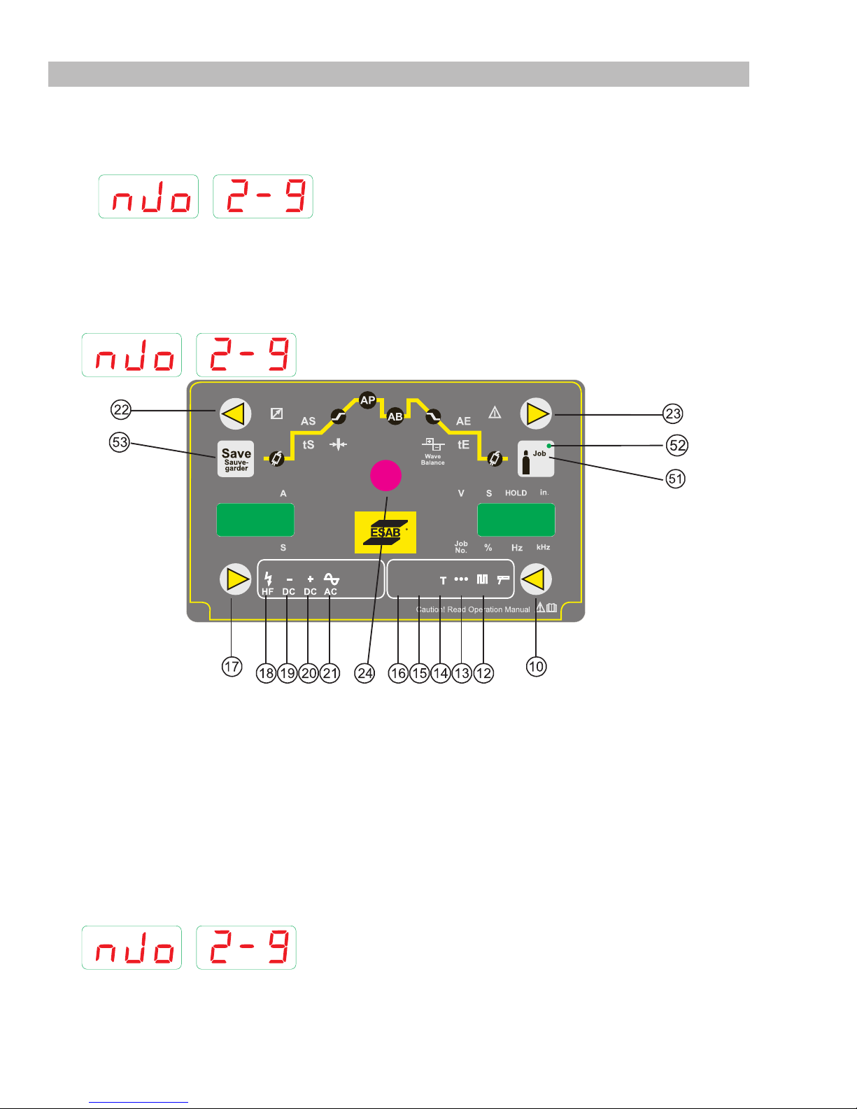
In GTAW modes, up to 100 jobs can be saved. These are arranged as 10 jobs numbers, in 10 job sets.
These are shown on the meter displays. The first number on the display is the job set, the second is the job number. In the example, the
job set is 2 and the job number is 9.
Saved TipTronic jobs can also be set as active or inactive.
Inactive jobs are skipped during TipTronic job selection.
TipTronic Operation
• Using the Welding Mode button (10) select TipTronic mode (14).
• Use the Multi Function Control (24) to select the job set number and the job number.
Note that if no TipTronic jobs are saved, it will not be possible to select any TipTronic jobs.
• Use the BACK button (22) or FORWARD button (22) to switch between TipTronic jobs and all main parameters.
4T2T
T
Art # A-12847
Figure 3-10: Tip Tronic Operation
Save a TipTronic Job (Only TIG parameters can be saved as Tip Tronic jobs)
• Set all the required GTAW welding parameters. Using the Welding Mode button (10) and the Welding Type button (17).
Do NOT select TipTronic mode (14) at this stage.
As an example, we may select HF, AC, 4T Pulse GTAW (LED’s 18, 21, 16 and 12 will be illuminated.
• Press the SAVE button (53).
The display will show the Job Number identification, the job set and job number.
• Use the Multi Function Control (24) to select the job set number and the job number.
• Press and hold the SAVE button (53) until all LED’s illuminate briefly to indicate a Save has been completed.
Note that you can interrupt the Save process, by simply briefly pushing the SAVE button (53)
INSTALLATION, OPERATION AND SETUP Manual 0-5346
3-20
Page 33
ET 220I AC/DC
Load a TipTronic Job
• Using the Welding Mode button (10) select TipTronic mode (14).
Either 2T or the 4T may be lighted as well as the TT symbol for Tip Tronic setting depending on the last saved job.
• Use the Multi Function Control (24) to select the job set number and the job number.
Set a TipTronic Job as Inactive
• Press the SAVE button (53).
The display will show the Job Number identification, the job set and job number.
• Use the Multi Function Control (24) to select the job set number and the job number.
• Press the GAS button (51). The light will toggle on and off as you press the button. Press the button so the light is off.
• The TipTronic job is now inactive. Note that the JOB LED (52) will extinguish.
• To exit this mode, press the SAVE button (53).
Set a TipTronic Job as Active
• Press the SAVE button (53).
The display will show the Job Number identification, the job set and job number.
• Use the Multi Function Control (24) to select the job set number and the job number.
• Press the GAS button (51). The light will toggle on and off as you press the button. Press the button so the light is on.
• The TipTronic job is now active. Note that the JOB LED (52) will illuminate.
• To exit this mode, press the SAVE button (53).
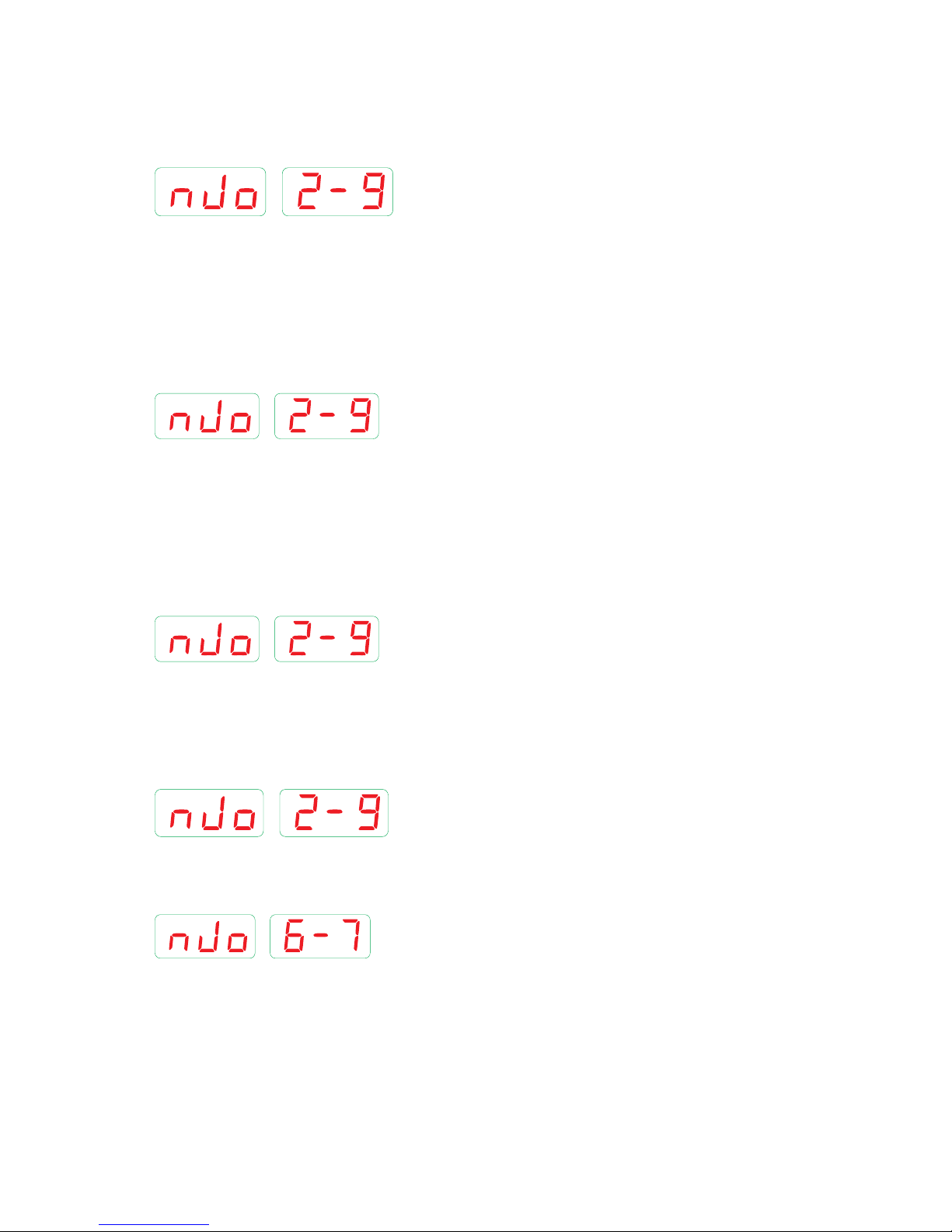
Copy a TipTronic Job to another Job Number
• Using the Welding Mode button (10) select TipTronic mode (14).
• Use the Multi Function Control (24) to select the “source” job set number and the job number.
In our example we are copying from Job Number 2-9.
• Press the SAVE button (53).
• Use the Multi Function Control (24) to select the “destination” job set number and the job number. In our example we are copying
to Job Number 6-7.
• Press and hold the SAVE button (54) until all LED’s illuminate briefly to indicate a Save has been completed.
Manual 0-5346 INSTALLATION, OPERATION AND SETUP
3-21
Page 34
ET 220I AC/DC
T
4T2T
Art # A-12848
3.14 Setup for Stick (SMAW) Welding
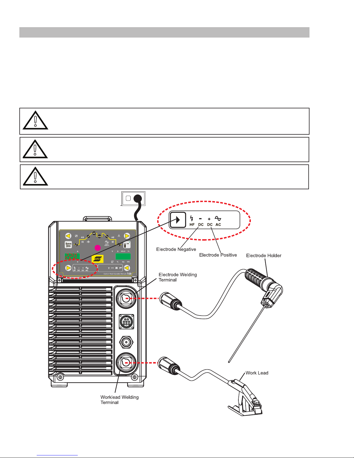
A. Connect the Electrode Holder lead to the Electrode welding terminal (top). If in doubt, consult the electrode manufacturer.
Welding current flows from the Power Source via 50mm Dinse type terminals. It is essential, however, that the male plug is
inserted and turned securely to achieve a sound electrical connection.
B. Connect the work lead to the Worklead welding terminal (bottom). If in doubt, consult the electrode manufacturer. Welding
current flows from the power source via 50mm Dinse type terminals. It is essential, however, that the male plug is inserted
and turned securely to achieve a sound electrical connection.
C. Select Stick and electrode positive mode with the welding mode and welding type buttons (refer to Section 3.15 for further
information)
WARNING
!
!
!
Before connecting the work clamp to the work and inserting the electrode in the electrode holder make
sure the mains power supply is switched off..
CAUTION
Remove any packaging material prior to use. Do not block the air vents at the front or rear of the Welding
Power Source.
CAUTION
Loose welding terminal connections can cause overheating and result in the male plug being fused in the
50mm Dinse type terminal.
Figure 3-11: Setup for Manual Arc Welding
INSTALLATION, OPERATION AND SETUP Manual 0-5346
3-22
Page 35
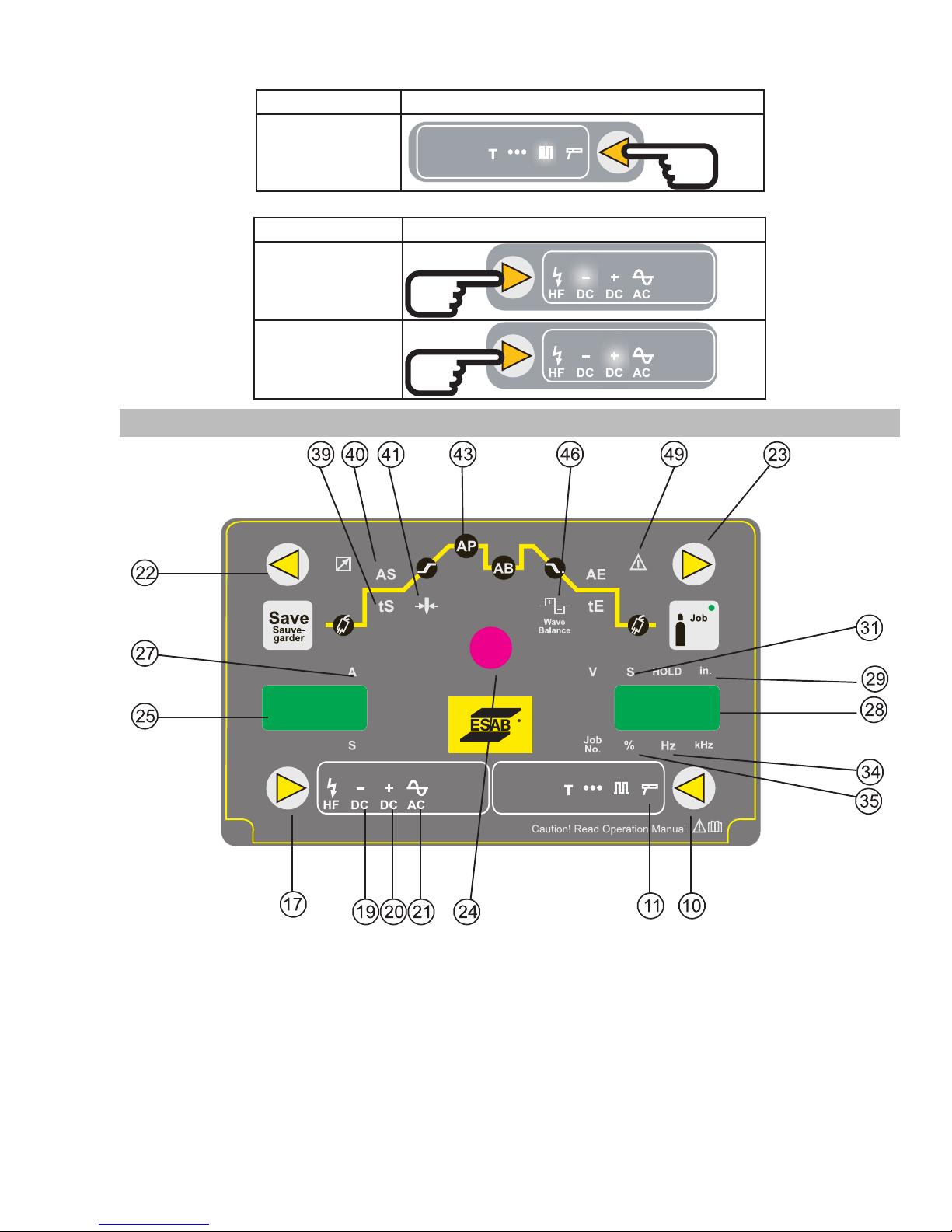
• First, select Stick Mode by pressing the Welding Mode (10) button.
Welding Type Welding Mode Selection
Stick Mode
2T
4T
T
• Then, select Welding Type by pressing the welding Type (17) button.
Welding Type Welding Type Selection
DC Negative Stick
DC Positive Stick
3.15 Stick (SMAW) Programming Mode
ET 220I AC/DC
• Press the WELDING MODE (10) button to select SMAW mode. The SMAW LED (11) will illuminate.
• Following SMAW operating modes are available.
DC Negative mode. DC Negative LED (19) will illuminate.
DC Positive mode. DC Positive LED (20) will illuminate.
• Press the BACK button (22) or FORWARD button (23) so the Electrode Diameter LED (41) and Inches LED (29) are illuminated.
Use the Multi Function Control (24) to adjust the Electrode size being used.
• Press the BACK button (22) or FORWARD button (23) so the Hot Start Amps LED (40) and % LED (35) are illuminated.
Manual 0-5346 INSTALLATION, OPERATION AND SETUP
4T2T
T
Figure 3-12: Stick Programming Mode
Art # A-12849
3-23
Page 36
ET 220I AC/DC
Inch
Use the Multi Function Control (24) to adjust the Hot Start Amps percentage.
• Press the BACK button (22) or FORWARD button (23) so the Hot Start Time LED (39) and Seconds LED (31) are illuminated.
Use the Multi Function Control (24) to adjust the Hot Start Amps Time.
• Press the BACK button (22) or FORWARD button (23) until the Peak Current LED (43) is illuminated.
Use the Multi Function Control (24) to adjust the Welding Current for the Electrode size being used. If the Welding Current does
not match the normal operating range of the electrode the Electrode Diameter Out-of-Range indictor LED (49) will illuminate.
If the Electrode Diameter Out-of-Range indictor LED (49) is illuminated, it is still possible to weld.
SMAW Electrode Diameter (inches) Nominal Welding Current (A)
1/16" (1.5mm) 20 - 40 Amps
3/32" (2.5mm) 45 - 100 Amps
1/8" (3.2mm) 75 - 140 Amps
5/32" (4.0mm) 130 -190 Amps
Table 3-7: Normal Welding Current for SMAW Electrode sizes
Parameter Range LED Code
(Left Display)
Parameter
Value
Factory
Setting
(Right Display)
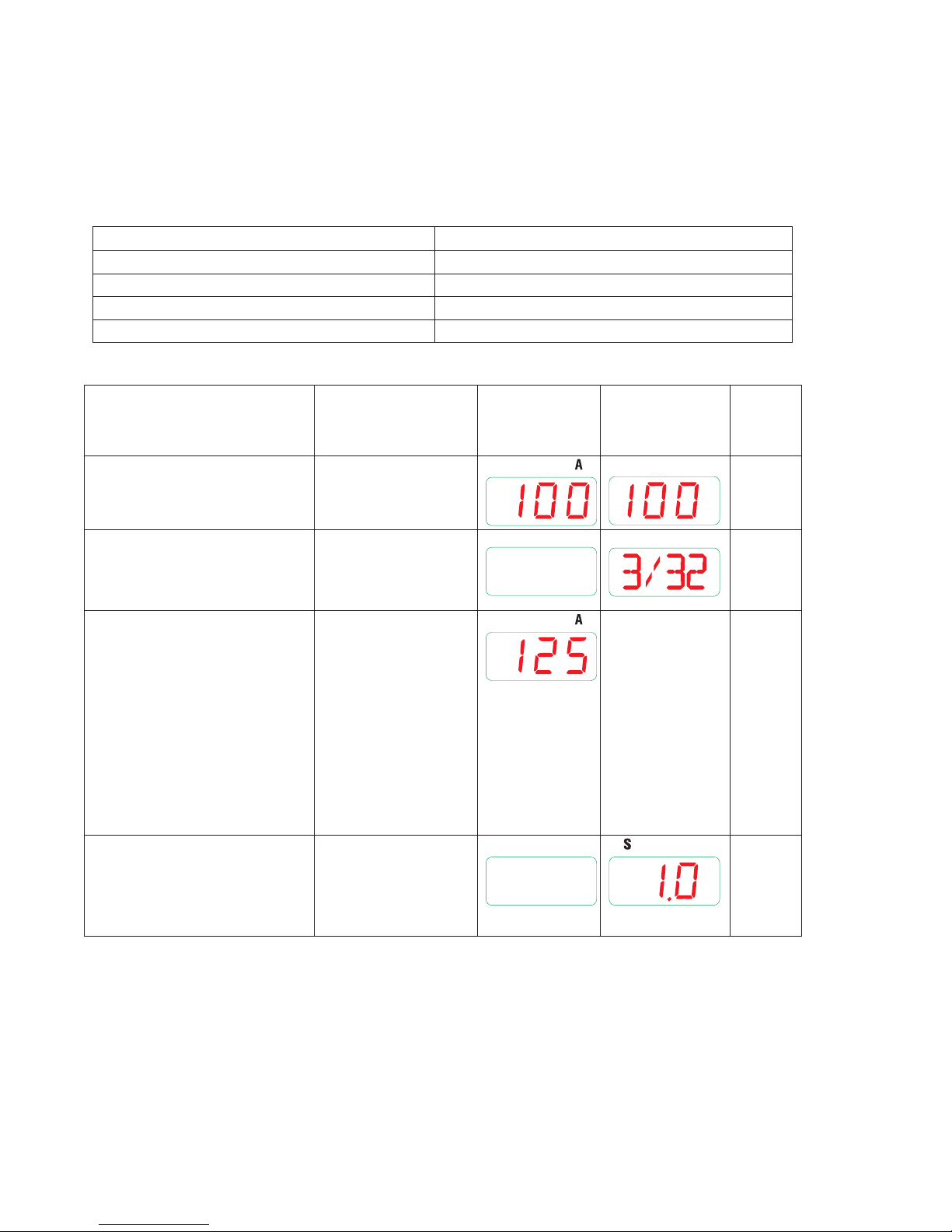
Welding Current A1
ET 220i AC/DC 10 - 170A 100
Electrode Diameter
ET 220i AC/DC
1/16" - 5/32"
3/32"
Set this parameters to the
electrode size being used.
Hot Start AS
This parameter operates in
SMAW mode and is used to
improve the start characteristics
for stick electrodes by adding
current on top of the welding
current.
e.g. HOT START current = 125
5 - 200% of Welding
Current A1
The maximum
welding current
in SMAW mode is
limited to 170A for
the ET 220i AC/DC.
125
When A1=100A
amps when welding current
= 100 amps & HOT START =
125%
Hot Start Time tS
This parameter sets the time
0 - 20 seconds 1.0
period for when the Hot Start
current is added to the welding
current at the start of the weld.
Table 3-8: SMAW Main Parameters
Secondary parameters are available. These are required to be set separately.
INSTALLATION, OPERATION AND SETUP Manual 0-5346
3-24
Page 37
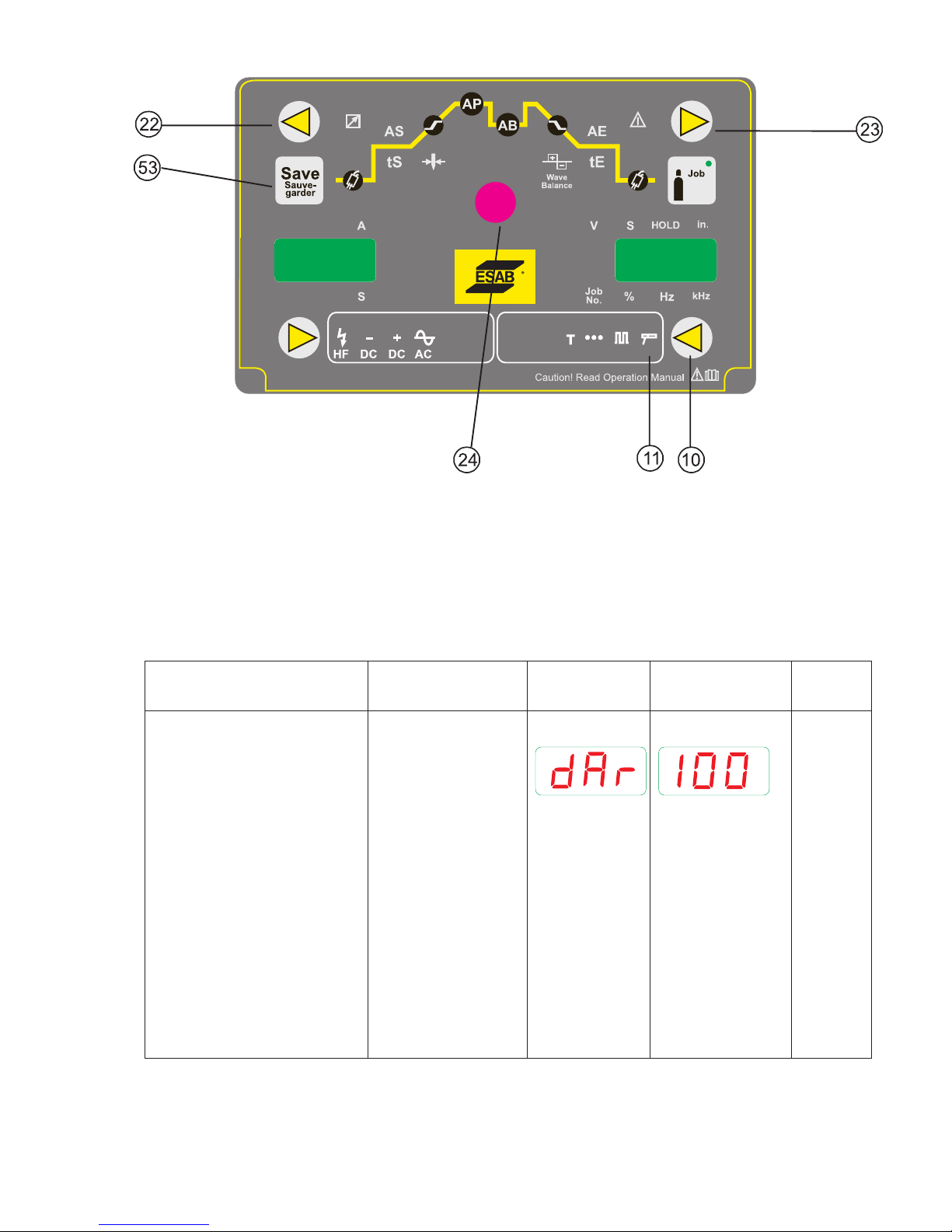
4T2T
T
Figure 3-13: Stick Programming Mode
ET 220I AC/DC
Art # A-12850
Press and hold the WELDING MODE (10) button then press the SAVE (53) button.
The Arc Dynamic Parameter is selected. In the left hand AMPS display dAr is displayed. In the right hand VOLTS display, the value of the
parameter is displayed.
Use the Multi Function Control (24) to adjust the Arc Dynamic parameter.
Press the BACK button (22) or FORWARD button (23) to select the Software Version Number. In the left hand AMPS display rEL is displayed. In the right hand VOLTS display, the Software Version Number is displayed.
Note that even during welding, these settings can be adjusted and changed.
Parameter Range LED Code
(Left Display)
Parameter Value
(Right Display)
Factory
Setting
Arc Dynamic
(Arc Force)
Arc Force is effective in SMAW
Mode only. Arc Force control
provides an adjustable amount
of Arc Force (or "dig"). This
feature can be particularly
beneficial in providing
the operator the ability to
compensate for variability in
joint fit-up in certain situations
with particular electrodes. In
general increasing the Arc
0 – 200%
The welding
current increases
automatically as the
welding voltage is
reduced. The Arc
Dynamic percentage
indicates the ratio
between the main
current and the
automatic increase.
100
Force control toward 200%
(maximum Arc Force) allows
greater penetration control to
be achieved.
Table 3-9: SMAW Secondary Parameters
Manual 0-5346 INSTALLATION, OPERATION AND SETUP
3-25
Page 38
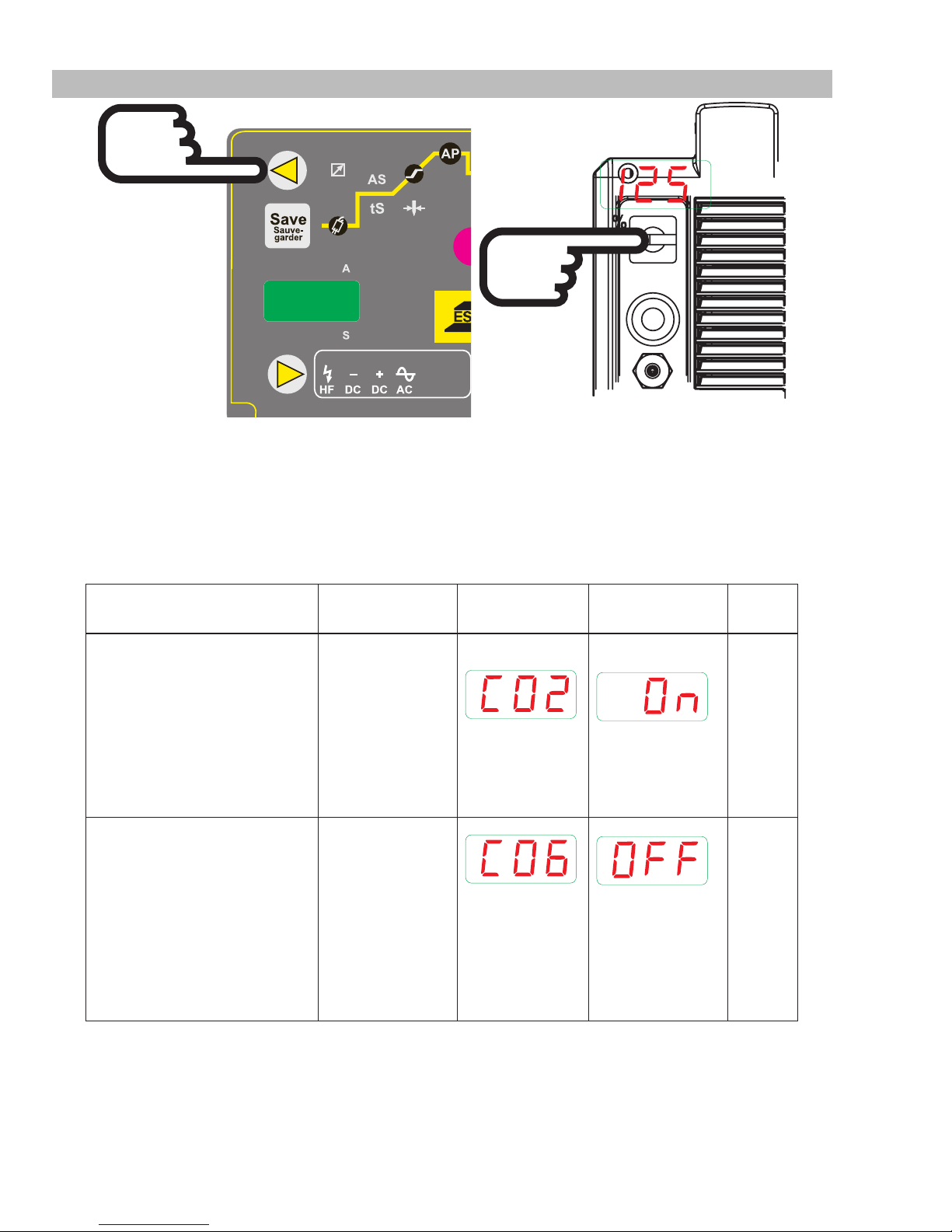
ET 220I AC/DC
Art # A-12851
3.16 User Specific Menus
Figure 3-14: User Specific Menus
• Switch off the power to the unit.
Press and hold the BACK Welding Parameter Button (22) .
Switch on the power to the unit.
The User Specific Menus are activated.
After the User Specific Menu items have been set, switch the power off to the unit to save the settings.
Menu item Range LED Code
Parameter Value
Factory
C02 – Water Pump Error
Message Display
Set this to “ON” if a water cooler
without a suitable interface lead
is being used.
Set this to “OFF” if a water
cooler with a suitable interface
lead is being used.
C06 – Downslope Mode
When set to “ON” in 4T mode,
the downslope will continue
even if the trigger is released
during the downslope time.
When set to “OFF” in 4T mode,
the downslope will stop as soon
as the trigger is released during
the downslope time.
ON
OFF
ON
OFF
(Left Display)
(Right Display)
Setting
ON
OFF
INSTALLATION, OPERATION AND SETUP Manual 0-5346
3-26
Page 39
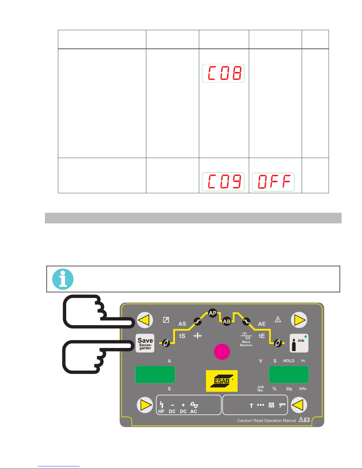
ET 220I AC/DC
Art # A-12852
Menu item Range LED Code
C08 – Foot Control Minimum
Current (GTAW AC mode only)
When set to “ON” the increased
Foot Control Minimum current
is disabled and the minimum
current on any electrode is 5A.
When set to “OFF” the increased
Foot Control Minimum current
is enabled.
The minimum currents are:
electrode 0.040" – 0.080" (10A)
electrode 3/32" (15A)
electrode 1/8" (20A)
C09
(SMAW mode only)
Set to “OFF”.
ON
(Left Display)
Parameter Value
(Right Display)
Factory
Setting
OFF
OFF
OFF OFF
Table 3-10: User Specific Menus
3.17 Special Function
Soft Reset
• Press and hold the BACK button (22).
• Press the SAVE button (53).
• All control panel LED’s will light up briefly to confirm the Soft Reset has been completed.
NOTE!
The only difference between soft & hard reset is that on a hard reset, presets or jobs will be erased. On a
soft reset they will remain.
Manual 0-5346 INSTALLATION, OPERATION AND SETUP
Figure 3-15: Soft Reset
4T2T
T
3-27
Page 40
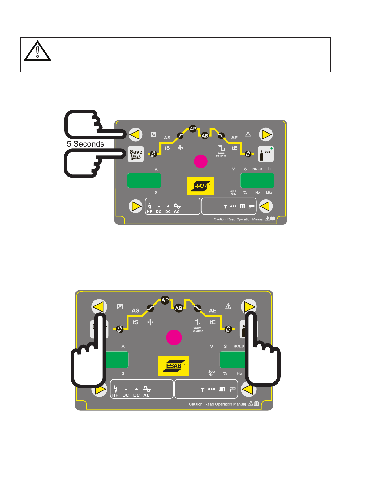
ET 220I AC/DC
Art # A_12853
Art # A-12854
Master Reset
WARNING
!
• Press and hold the BACK button (22).
• Press the hold the SAVE button (53).
• All control panel LED’s will light up briefly to confirm the Soft Reset has been completed. After 5 seconds all the control panel
LED’s will light again briefly to confirm the Master Reset has been completed.
All saved TipTronic jobs will be erased.
All welding and secondary parameters will be restored to the factory setting.
Figure 3-16: Master Reset
Control Panel Test
• Press and hold the BACK button (22).
• Press the FORWARD button (23).
• All control panel LED’s and meter displays will light up for approximately 4 seconds.
4T2T
T
4T2T
T
Figure 3-17: Control Panel Test
INSTALLATION, OPERATION AND SETUP Manual 0-5346
3-28
Page 41
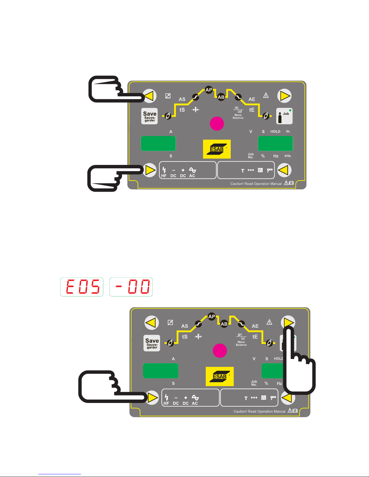
ET 220I AC/DC
Art # A-12855
Art # A-12856
Fan Test
• Press and hold the BACK button (22).
• Press the WELDING TYPE button (17).
• The fan will run for approximately 30 seconds.
• If the BACK button (22) and WELDING TYPE button (17) are pressed again while the fan is running, the fan test is halted.
4T2T
T
Figure 3-18: Fan Test
Water Pump Test
Only for water pump with Net Connection interface
• Press and hold the FORWARD button (22).
• Press the WELDING TYPE button (17).
• The Water Cooler (Net Connection type) will run for approximately 30 seconds.
If there is an error, or no pump is connected, the error message
Will be displayed after approximately 5 seconds.
Manual 0-5346 INSTALLATION, OPERATION AND SETUP
Figure 3-19: Water Pump Test
4T2T
T
3-29
Page 42
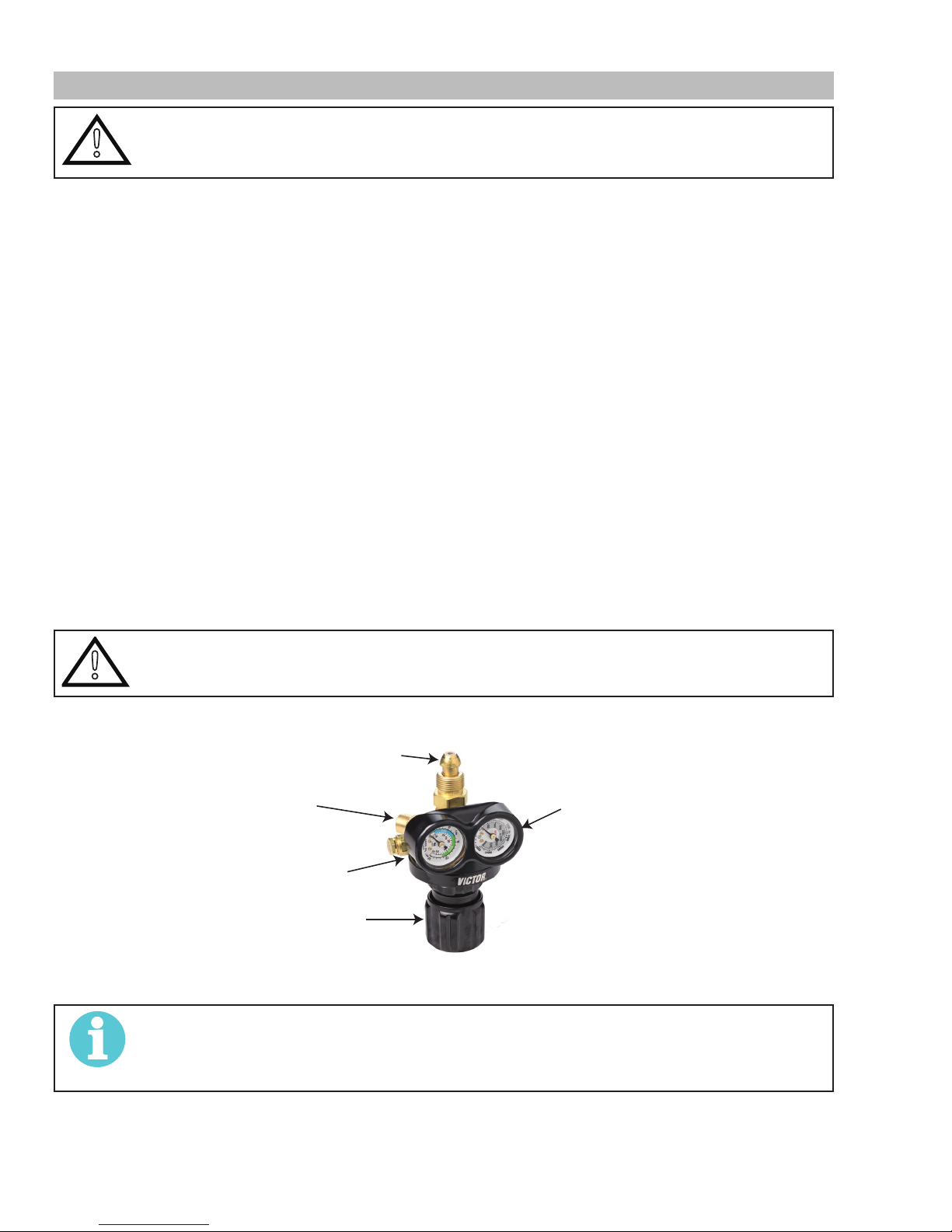
ET 220I AC/DC
3.18 Shielding Gas Regulator/ Flowmeter Operating Instructions
WARNING
!
Shielding Gas Regulator/ Flowmeter Safety
This regulator/ flowmeter is designed to reduce and control high pressure gas from a cylinder or pipeline to the working pressure
required for the equipment using it.
If the equipment is improperly used, hazardous conditions are created that may cause accidents. It is the users responsibility to prevent
such conditions. Before handing or using the equipment, understand and comply at all times with the safe practices prescribed in this
instruction.
SPECIFIC PROCEDURES for the use of regulators/ flowmeters are listed below.
1. NEVER subject the regulator/ flowmeter to inlet pressure greater than its rated inlet pressure.
2. NEVER pressurize a regulator/ flowmeter that has loose or damaged parts or is in a questionable condition. NEVER loosen a
3. DO NOT remove the regulator/ flowmeter from a cylinder without first closing the cylinder valve and releasing gas in the regu-
4. DO NOT use the regulator/ flowmeter as a control valve. When downstream equipment is not in use for extended periods of
5. OPEN the cylinder valve SLOWLY. Close after use.
User Responsibilities
This equipment will perform safely and reliable only when installed, operated and maintained, and repaired in accordance with the
instructions provided. Equipment must be checked periodically and repaired, replaced, or reset as necessary for continued safe and reliable performance. Defective equipment should not be used. Parts that are broken, missing, obviously worn, distorted, or contaminated
should be replaced immediately.
The user of this equipment will generally have the sole responsibility for any malfunction, which results from improper use, faulty maintenance, or by repair by anyone other than an accredited repairer.
!
This equipment is designed for use with welding grade (Inert) shielding gases only.
connection or attempt to remove any part of a regulator/ flowmeter until the gas pressure has been relieved. Under pressure,
gas can dangerously propel a loose part.
lator/ flowmeter high and low pressure chambers.
time, shut off the gas at the cylinder valve and release the gas from the equipment.
CAUTION
Match regulator/ flowmeter to cylinder. NEVER CONNECT a regulator/ flowmeter designed for a particular
gas or gases to a cylinder containing any other gas.
INLET
CONNECTION
OUTLET
CONNECTION
FLOW GAUGE (DELIVERY)
PRESSURE
ADJUSTING
SCREW
HIGH PRESSURE
GAUGE (SUPPLY)
Art # A-12126
Figure 3-20: Fit Regulator/ Flowmeter to Cylinder
NOTE!
The regulator/ flowmeter used with argon based and carbon dioxide shielding gases are different. The
regulator/ flowmeter supplied is for argon based shielding gases. If carbon dioxide is to be used a suitable
carbon dioxide regulator/ flowmeter will need to be fitted.
INSTALLATION, OPERATION AND SETUP Manual 0-5346
3-30
Page 43
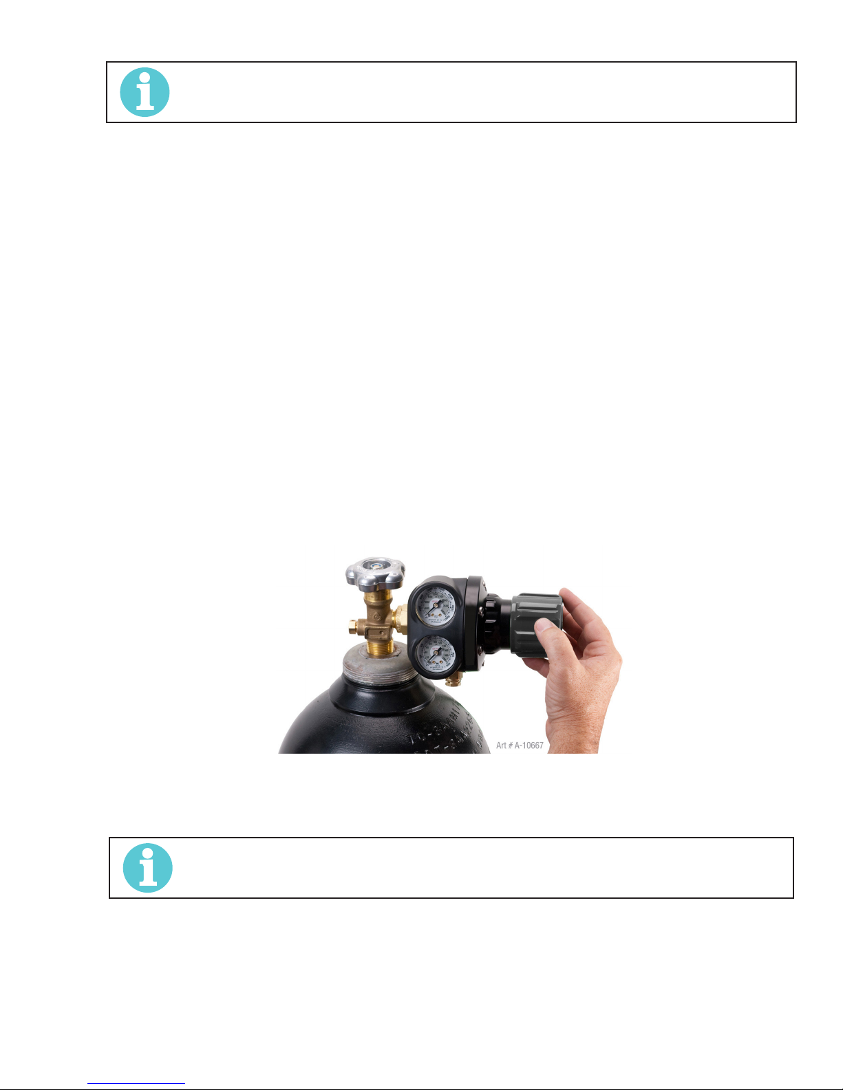
ET 220I AC/DC
NOTE!
All valves downstream of the regulator/ flowmeter must be opened to obtain a true flow rate reading on the
outlet gauge. (Welding power source must be triggered) Close the valves after the pressure has been set.
Installation
1. Remove cylinder valve plastic dust seal. Clean the cylinder valve outlet of impurities that may clog orifices and damage seats
before connecting the regulator/ flowmeter.
Crack the valve (open then close) momentarily, pointing the outlet away from people and sources of ignition. Wipe with a clean
lint free cloth.
2. Match regulator/ flowmeter to cylinder. Before connecting, check that the regulator/ flowmeter label and cylinder marking
agree and that the regulator/ flowmeter inlet and cylinder outlet match. NEVER CONNECT a regulator/ flowmeter designed for a
particular gas or gases to a cylinder containing any other gas.
3. Connect the regulator/ flowmeter inlet connection to cylinder or pipeline and tighten it firmly but not excessively, with a suitable spanner.
4. Connect and tighten the outlet hose firmly and attach down-stream equipment.
5. To protect sensitive down-stream equipment a separate safety device may be necessary if the regulator/ flowmeter is not fitted with a pressure relief device.
Operation
With the regulator/ flowmeter connected to cylinder or pipeline, and the adjustment screw/knob fully disengaged, pressurize as follows:
1. Stand to one side of regulator/ flowmeter and slowly open the cylinder valve. If opened quickly, a sudden pressure surge may
damage internal regulator/ flowmeter parts.
2. With valves on downstream equipment closed, adjust regulator/ flowmeter to approximate working pressure. It is recommended that testing for leaks at the regulator/ flowmeter connection points be carried out using a suitable leak detection solution or
soapy water.
3. Purge air or other unwanted welding grade shielding gas from equipment connected to the regulator/ flowmeter by individually
opening then closing the equipment control valves. Complete purging may take up to ten seconds or more, depending upon the
length and size of the hose being purged.
Adjusting Flow Rate
With the regulator/ flowmeter ready for operation, adjust working flow rate as follows:
1. Slowly turn adjusting screw/knob in (clockwise) direction until the outlet gauge indicates the required flow rate.
NOTE!
It may be necessary to re-check the shielding gas regulator/ flowmeter flow rate following the first weld
sequence due to back pressure present within shielding gas hose assembly.
2. To reduce flow rate, allow the welding grade shielding gas to discharge from regulator/ flowmeter by opening the downstream
valve. Bleed welding grade shielding gas into a well ventilated area and away from any ignition source. Turn adjusting screw
counter clockwise, until the required flow rate is indicated on the gauge. Close downstream valve.
Manual 0-5346 INSTALLATION, OPERATION AND SETUP
Figure 3-21: Adjust Flow Rate
3-31
Page 44
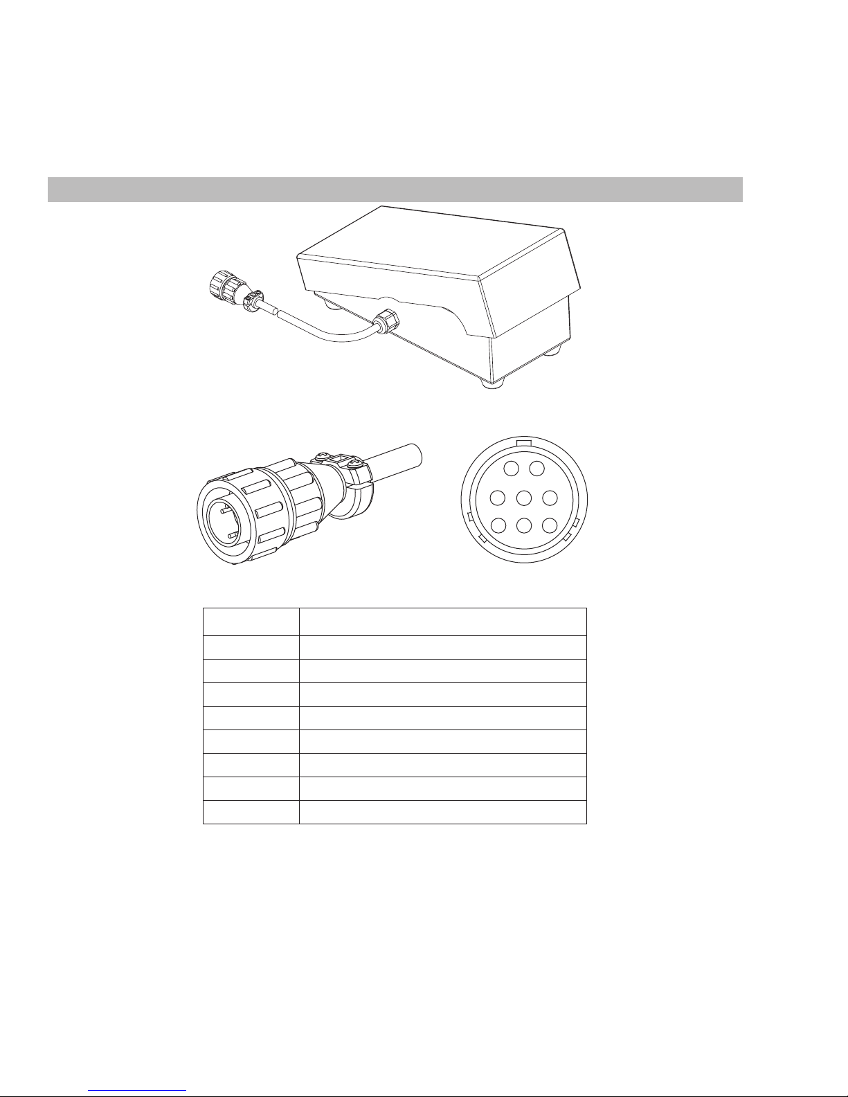
ET 220I AC/DC
Art # A-11340
Shutdown
Close cylinder valve whenever the regulator/ flowmeter is not in use. To shut down for extended periods (more than 30 minutes).
1. Close cylinder or upstream valve tightly.
2. Open downstream equipment valves to drain the lines. Bleed gas into a well ventilated area and away from any ignition source.
3. After gas is drained completely, disengage adjusting screw and close downstream equipment valves.
4. Before transporting cylinders that are not secured on a cart designed for such purposes, remove regulators/ flowmeters.
3.19 Foot Control, Part No. W4013200 (Optional Accessory)
Art # A-11338
Figure 3-22: Foot Control
Art # A-11339
Figure 3-23: 8 Pin Control Plug
Pin Description
1 Not Used
2 Trigger Switch
3 Trigger Switch
4 Not Used
5 Potentiometer Maximum
6 Potentiometer Minimum
7 Potentiometer Wiper
8 Not Used
Table 3-11: 8 Pin Socket
2
1
345
6
7
8
INSTALLATION, OPERATION AND SETUP Manual 0-5346
3-32
Page 45
ET 220I AC/DC
Description
The Tweco Foot Control is a foot operated switch and potentiometer which starts and stops the welding process and controls welding
current through operation of the foot pedal. Refer to list below for compatible Tweco power sources.
Installation
Attach the 8-pin connector on the end of the cable to the 8-pin receptacle on the front of the welding machine. To complete the connection, align the keyway, insert the plug, and rotate the threaded collar fully clockwise.
Foot Control Operation
The foot control listed above Part Number W4013200 foot control will allow you to adjust the maximum output preset amperage. Other
8 pin remote's used with some of our other welders will function as below.
Press the foot pedal to start the machine output functions. The foot control potentiometer controls the welding current up to the level
set on the welding power source. Note that the maximum current must be set on the power source by the operator prior to the foot
control being connected. With the foot control connected, the power source will only display minimum preview Amps until the foot control is depressed then it displays actual welding current when welding. Pressing the pedal to increases the welding current; letting up
on the pedal decreases the welding current. Releasing the pedal completely extinguishes the arc and initiates the post-flow shielding
gas timer (where fitted).
Note that some power sources may require the remote/local switch set to remote, the maximum setting of the power source will be determined by the respective front panel control, irrespective of the remote control device setting. As an example, if the output current on
the power source front panel is set to 50% of the available current and the remote control device is set to 100% output or maximum,
the maximum achievable output from the unit will be 50%. Should 100% output be required, the respective front panel control must be
set to 100% or maximum, in which case the remote device will then be able to control between 1-100% output.
NOTE!
Note 1: Some power sources other than specified as above may not function with the foot control.
Note 2: The foot control will only work correctly when power source trigger mode 2T (Normal) is selected.
Manual 0-5346 INSTALLATION, OPERATION AND SETUP
3-33
Page 46

ET 220I AC/DC
This Page Intentionally Blank
INSTALLATION, OPERATION AND SETUP Manual 0-5346
3-34
Page 47

ET 220I AC/DC
SECTION 4:
BASIC WELDING GUIDE
4.01 Stick (SMAW) Basic Welding Technique
Size of Electrode
The electrode size is determined by the thickness of metals being joined and can also be governed by the type of welding machine
available. Small welding machines will only provide sufficient current (amperage) to run the smaller size electrodes.
For thin sections, it is necessary to use smaller electrodes otherwise the arc may burn holes through the job. A little practice will soon
establish the most suitable electrode for a given application.
Storage of Electrodes
Always store electrodes in a dry place and in their original containers.
Electrode Polarity
Electrodes are generally connected to the ELECTRODE HOLDER with the Electrode Holder connected positive polarity. The WORK LEAD
is connected negative polarity and is connected to the work piece. If in doubt consult the electrode data sheet or your nearest Accredited ESAB Distributor.
Effects of Arc Welding Various Materials
A. High tensile and alloy steels
The two most prominent effects of welding these steels are the formation of a hardened zone in the weld area, and, if suitable precautions are not taken, the occurrence in this zone of under-bead cracks may result. Hardened zone and under-bead cracks in the
weld area may be reduced by using the correct electrodes, preheating, using higher current settings, using larger electrodes sizes,
short runs for larger electrode deposits or tempering in a furnace.
Hydrogen controlled Electrodes must be used for this application.
B. Austenitic manganese steels
The effect on manganese steel of slow cooling from high temperatures is to embrittle it. For this reason it is absolutely essential to
keep manganese steel cool during welding by quenching after each weld or skip welding to distribute the heat.
C. Cast Iron
Most types of cast iron, except white iron, are weldable. White iron, because of its extreme brittleness, generally cracks when attempts are made to weld it. Trouble may also be experienced when welding white-heart malleable, due to the porosity caused by
gas held in this type of iron.
D. Copper and alloys
The most important factor is the high rate of heat conductivity of copper, making preheating of heavy sections necessary to give
proper fusion of weld and base metal.
Arc Welding Practice
The techniques used for arc welding are almost identical regardless of what types of metals are being joined. Naturally enough, different types of electrodes would be used for different metals as described in the preceding section.
Welding Position
The electrodes dealt with in this publication can be used in most positions, i.e. they are suitable for welding in flat, horizontal, vertical
and overhead positions. Numerous applications call for welds to be made in positions intermediate between these. Some of the common types of welds are shown in Figures 4-5 through 4-12.
Manual 0-5346 BASIC WELDING GUIDE
Art # A-07687
Figure 4-1: Flat Position, Down Hand Butt Weld
4-1
Page 48
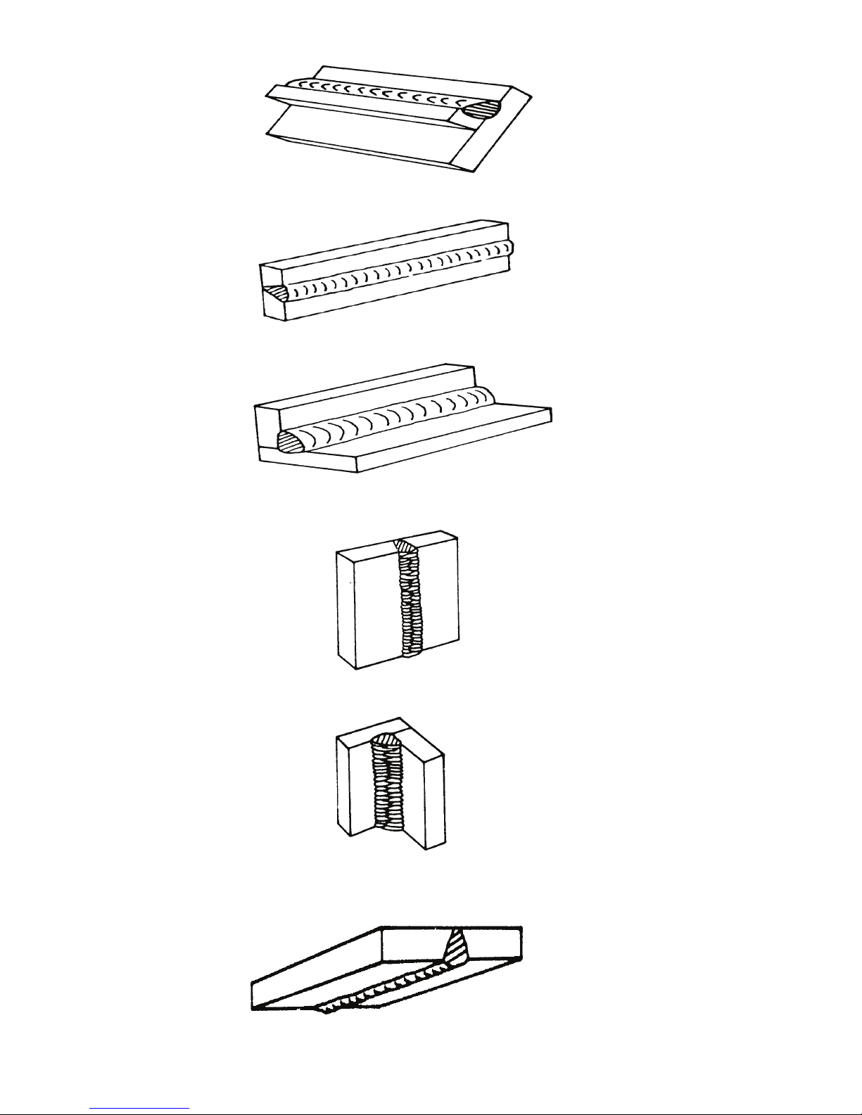
ET 220I AC/DC
Art # A-07688
Art # A-07689
Art # A-07690
Figure 4-2: Flat Position, Gravity Fillet Weld
Figure 4-3: Horizontal Position, Butt Weld
Figure 4-4: Horizontal-Vertical (HV) Position
Art A-07691
Figure 4-5: Vertical Position, Butt Weld
Art # A-07692
Figure 4-6: Vertical Position, Fillet Weld
Art# A-07693
Figure 4-7: Overhead Position, Butt Weld
BASIC WELDING GUIDE Manual 0-5346
4-2
Page 49
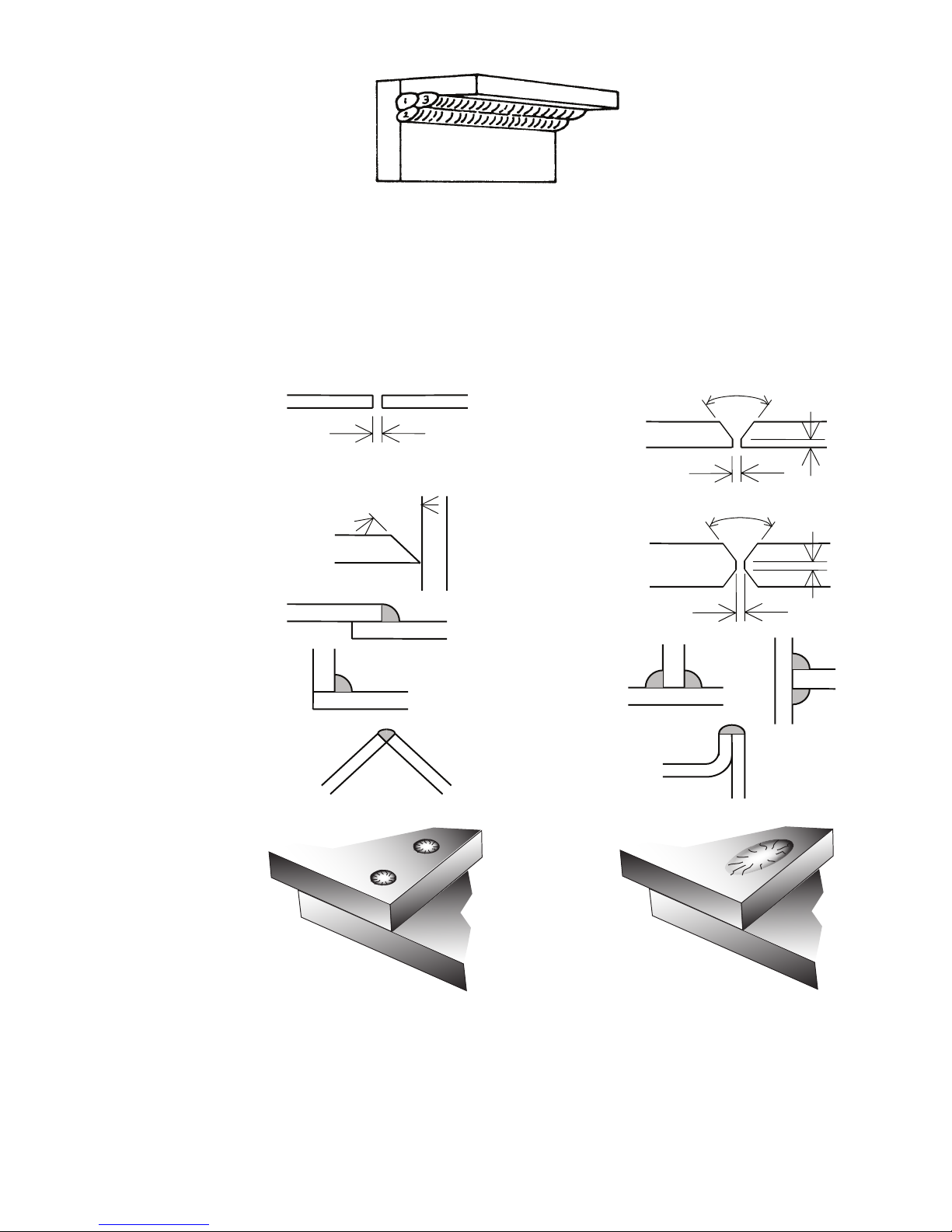
ET 220I AC/DC
Open Square Butt
x
Single Vee Butt Joint
Not less than
Art # A-07694
Figure 4-8: Overhead Position, Fillet Weld
Joint Preparations
In many cases, it will be possible to weld steel sections without any special preparation. For heavier sections and for repair work on
castings, etc., it will be necessary to cut or grind an angle between the pieces being joined to ensure proper penetration of the weld
metal and to produce sound joints.
In general, surfaces being welded should be clean and free of rust, scale, dirt, grease, etc. Slag should be removed from oxy-cut surfaces. Typical joint designs are shown in Figure 4-9.
Joint
Gap varies from
1.6mm (1/16”) to 4.8mm (3/16”)
depending on plate thickness
Single Vee Butt Joint
Lap Joint
Fillet Joint
Corner Weld
Not less than
45°
(Fillet both sides of the
1.6mm (1/16”)
Double Vee Butt Joint
1.6mm (1/16”)
Tee Joints
joint)
Edge Joint
70°
Not less than
70°
1.6mm (1/16” ) ma
1.6mm (1/16”) max
Art # A-07695_AE
Manual 0-5346 BASIC WELDING GUIDE
Plug Weld Plug Weld
Figure 4-9: Typical Joint Designs for Arc Welding
4-3
Page 50
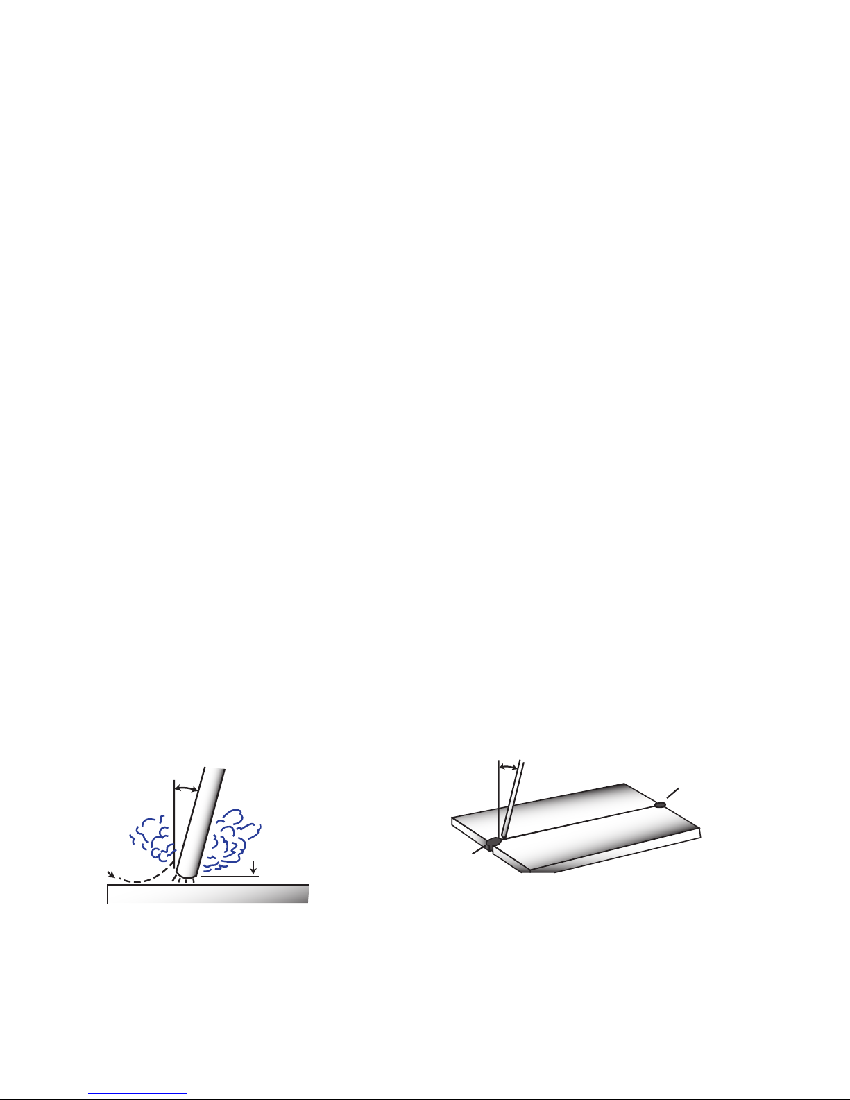
ET 220I AC/DC
20°
1.6 mm (1/16”)
T
20°-30°
Arc Welding Technique - A Word to Beginners
For those who have not yet done any welding, the simplest way
to commence is to run beads on a piece of scrap plate. Use mild
steel plate about 1/4" thick and a 1/8" electrode. Clean any
paint, loose scale or grease off the plate and set it firmly on the
work bench so that welding can be carried out in the downhand position. Make sure that the work clamp is making good
electrical contact with the work, either directly or through the
work table. For light gauge material, always clamp the work lead
directly to the job, otherwise a poor circuit will probably result.
The Welder
Place yourself in a comfortable position before beginning to weld.
Get a seat of suitable height and do as much work as possible
sitting down. Don't hold your body tense. A taut attitude of mind
and a tensed body will soon make you feel tired. Relax and you
will find that the job becomes much easier. You can add much to
your peace of mind by wearing a leather apron and gauntlets. You
won't be worrying then about being burnt or sparks setting alight
to your clothes.
Place the work so that the direction of welding is across, rather
than to or from, your body. The electrode holder lead should be
clear of any obstruction so that you can move your arm freely
along as the electrode burns down. If the lead is slung over your
shoulder, it allows greater freedom of movement and takes a
lot of weight off your hand. Be sure the insulation on your cable
and electrode holder is not faulty, otherwise you are risking an
electric shock.
Striking the Arc
Practice this on a piece of scrap plate before going on to more
exacting work. You may at first experience difficulty due to the tip
of the electrode "sticking" to the work piece. This is caused by
making too heavy a contact with the work and failing to withdraw
the electrode quickly enough. A low amperage will accentuate it.
This freezing-on of the tip may be overcome by scratching the
electrode along the plate surface in the same way as a match
is struck. As soon as the arc is established, maintain a 1/16"
to 1/8" gap between the burning electrode end and the parent
metal. Draw the electrode slowly along as it melts down.
Another difficulty you may meet is the tendency, after the arc is
struck, to withdraw the electrode so far that the arc is broken
again. A little practice will soon remedy both of these faults.
Art # A-07696_AB
blobs. The weld bead is flattened and spatter increases. A short
arc is essential if a high quality weld is to be obtained although
if it is too short there is the danger of it being blanketed by slag
and the electrode tip being solidified in. If this should happen,
give the electrode a quick twist back over the weld to detach it.
Rate of Travel
After the arc is struck, your next concern is to maintain it, and
this requires moving the electrode tip towards the molten pool at
the same rate as it is melting away. At the same time, the electrode has to move along the plate to form a bead. The electrode
is directed at the weld pool at about 20º from the vertical. The
rate of travel has to be adjusted so that a well-formed bead is
produced.
If the travel is too fast, the bead will be narrow and strung out
and may even be broken up into individual globules. If the travel
is too slow, the weld metal piles up and the bead will be too
large.
Making Welded Joints
Having attained some skill in the handling of an electrode, you
will be ready to go on to make up welded joints.
A. Butt Welds
Set up two plates with their edges parallel, as shown in Figure
4-11, allowing 1/16" to 3/32" gap between them and tack weld
at both ends. This is to prevent contraction stresses from the
cooling weld metal pulling the plates out of alignment. Plates
thicker than 1/4" should have their mating edges bevelled to
form a 70º to 90º included angle. This allows full penetration
of the weld metal to the root. Using a 1/8" electrode, deposit
weld metal on the bottom of the joint.
Do not weave the electrode, but maintain a steady rate of
travel along the joint sufficient to produce a well-formed
bead. At first you may notice a tendency for undercut to form,
but keeping the arc length short, the angle of the electrode at
about 20º from vertical, and the rate of travel not too fast, will
help eliminate this. The electrode needs to be moved along
fast enough to prevent the slag pool from getting ahead of the
arc. To complete the joint in thin plate, turn the job over, clean
the slag out of the back and deposit a similar weld.
Electrode
Tack Weld
Figure 4-10: Striking an Arc
Arc Length
The securing of an arc length necessary to produce a neat weld
soon becomes almost automatic. You will find that a long arc produces more heat. A very long arc produces a crackling or spluttering noise and the weld metal comes across in large, irregular
BASIC WELDING GUIDE Manual 0-5346
4-4
ack Weld
Art # A-07697_AB
Figure 4-11: Butt Weld
Page 51
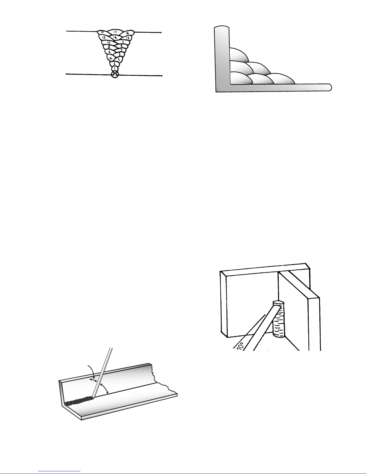
ET 220I AC/DC
Art # A-07699_AB
Art # A-07700_AB
6
Art # A-07698
Figure 4-12: Weld Build up Sequence
Heavy plate will require several runs to complete the joint.
After completing the first run, chip the slag out and clean the
weld with a wire brush. It is important to do this to prevent
slag being trapped by the second run. Subsequent runs are
then deposited using either a weave technique or single beads
laid down in the sequence shown in Figure 4-12. The width
of weave should not be more than three times the core wire
diameter of the electrode. When the joint is completely filled,
the back is either machined, ground or gouged out to remove
slag which may be trapped in the root, and to prepare a suitable joint for depositing the backing run. If a backing bar is
used, it is not usually necessary to remove this, since it serves
a similar purpose to the backing run in securing proper fusion
at the root of the weld.
B. Fillet Welds
These are welds of approximately triangular cross-section
made by depositing metal in the corner of two faces meeting
at right angles. Refer to Figure 4-4.
A piece of angle iron is a suitable specimen with which to
begin, or two lengths of strip steel may be tacked together at
right angles. Using a 1/8" electrode, position angle iron with
one leg horizontal and the other vertical. This is known as a
horizontal-vertical (HV) fillet. Strike the arc and immediately
bring the electrode to a position perpendicular to the line of the
fillet and about 45º from the vertical. Some electrodes require
to be sloped about 20º away from the perpendicular position to
prevent slag from running ahead of the weld. Refer to Figure
4-13. Do not attempt to build up much larger than 1/4" width
with a 1/8" electrode, otherwise the weld metal tends to sag
towards the base, and undercut forms on the vertical leg.
Multi-runs can be made as shown in Figure 4-14. Weaving in
HV fillet welds is undesirable.
3
1
5
2
4
Figure 4-14: Multi-runs in HV Fillet Weld
C. Vertical Welds
1. Vertical Up
Tack weld a three feet length of angle iron to your work
bench in an upright position. Use a 1/8" electrode. Make
yourself comfortable on a seat in front of the job and
strike the arc in the corner of the fillet. The electrode
needs to be about 10º from the horizontal to enable a
good bead to be deposited. Refer Figure 4-15. Use a
short arc, and do not attempt to weave on the first run.
When the first run has been completed de-slag the
weld deposit and begin the second run at the bottom.
This time a slight weaving motion is necessary to cover
the first run and obtain good fusion at the edges. At the
completion of each side motion, pause for a moment to
allow weld metal to build up at the edges, otherwise undercut will form and too much metal will accumulate in
the centre of the weld. Figure 4-16 illustrates multi-run
technique and Figure 4-17 shows the effects of pausing
at the edge of weave and of weaving too rapidly.
Art # A-07701
45° from
vertical
60° - 70° from line
of weld
Figure 4-13: Electrode Position for HV Fillet Weld
Manual 0-5346 BASIC WELDING GUIDE
Figure 4-15: Single Run Vertical Fillet Weld
4-5
Page 52
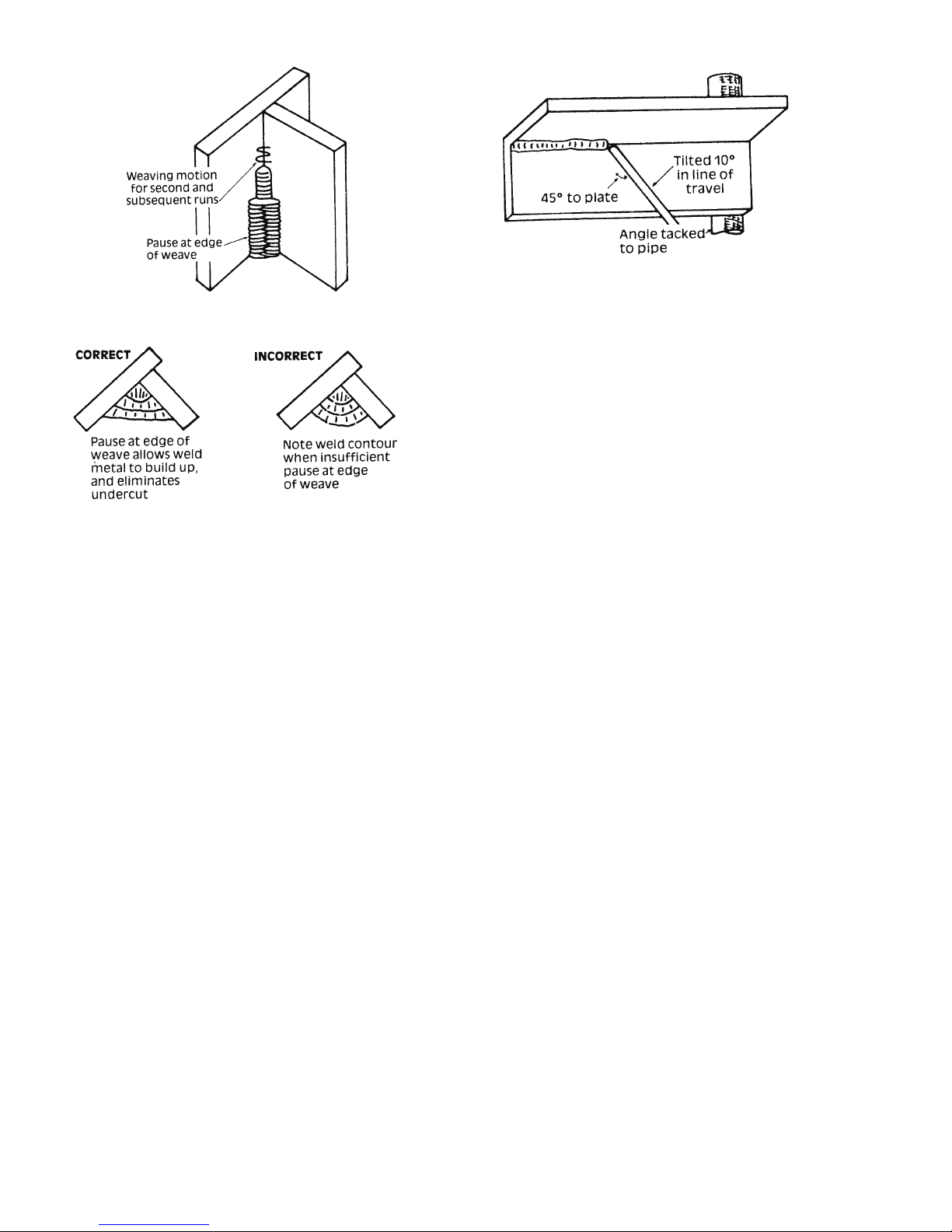
ET 220I AC/DC
Art # A-07702
Art # A-07704
Figure 4-18: Overhead Fillet Weld
Figure 4-16: Multi Run Vertical Fillet Weld
Art # A-07703
Figure 4-17: Examples of Vertical Fillet Welds
2. Vertical Down
Use an 1/8" electrode. The tip of the electrode is held in
light contact with the work and the speed of downward
travel is regulated so that the tip of the electrode just
keeps ahead of the slag. The electrode should point
upwards at an angle of about 45º.
3. Overhead Welds
Apart from the rather awkward position necessary,
overhead welding is not much more difficult that downhand welding. Set up a specimen for overhead welding
by first tacking a length of angle iron at right angles to
another piece of angle iron or a length of waste pipe.
Then tack this to the work bench or hold in a vice so
that the specimen is positioned in the overhead position
as shown in the sketch. The electrode is held at 45º to
the horizontal and tilted 10º in the line of travel (Figure
4-18). The tip of the electrode may be touched lightly
on the metal, which helps to give a steady run. A weave
technique is not advisable for overhead fillet welds. Deposit the first run by simply drawing the electrode along
at a steady rate. You will notice that the weld deposit
is rather convex, due to the effect of gravity before the
metal freezes.
Distortion
Distortion in some degree is present in all forms of welding. In
many cases it is so small that it is barely perceptible, but in other
cases allowance has to be made before welding commences for
the distortion that will subsequently occur. The study of distortion
is so complex that only a brief outline can be attempted hear.
The Cause of Distortion
Distortion is caused by:
A. Contraction of Weld Metal:
Molten steel shrinks approximately 11 per cent in volume on
cooling to room temperature. This means that a cube of molten
metal would contract approximately 2.2 per cent in each of
its three dimensions. In a welded joint, the metal becomes
attached to the side of the joint and cannot contract freely.
Therefore, cooling causes the weld metal to flow plastically,
that is, the weld itself has to stretch if it is to overcome the
effect of shrinking volume and still be attached to the edge of
the joint. If the restraint is very great, as, for example, in a heavy
section of plate, the weld metal may crack. Even in cases where
the weld metal does not crack, there will still remain stresses
"Locked-up" in the structure. If the joint material is relatively
weak, for example, a butt joint in thin sheet, the contracting
weld metal may cause the sheet to become distorted.
B. Expansion and Contraction of Parent Metal in the
Fusion Zone:
While welding is proceeding, a relatively small volume of the
adjacent plate material is heated to a very high temperature
and attempts to expand in all directions. It is able to do this
freely at right angles to the surface of the plate (i.e., "through
the weld", but when it attempts to expand "across the weld" or
"along the weld", it meets considerable resistance, and to fulfil
the desire for continued expansion, it has to deform plastically,
that is, the metal adjacent to the weld is at a high temperature
and hence rather soft, and, by expanding, pushes against the
cooler, harder metal further away, and tends to bulge (or is
"upset". When the weld area begins to cool, the "upset" metal
attempts to contract as much as it expanded, but, because it
has been "upset" it does not resume its former shape, and the
contraction of the new shape exerts a strong pull on adjacent
metal. Several things can then happen.
The metal in the weld area is stretched (plastic deformation),
the job may be pulled out of shape by the powerful contraction
BASIC WELDING GUIDE Manual 0-5346
4-6
Page 53
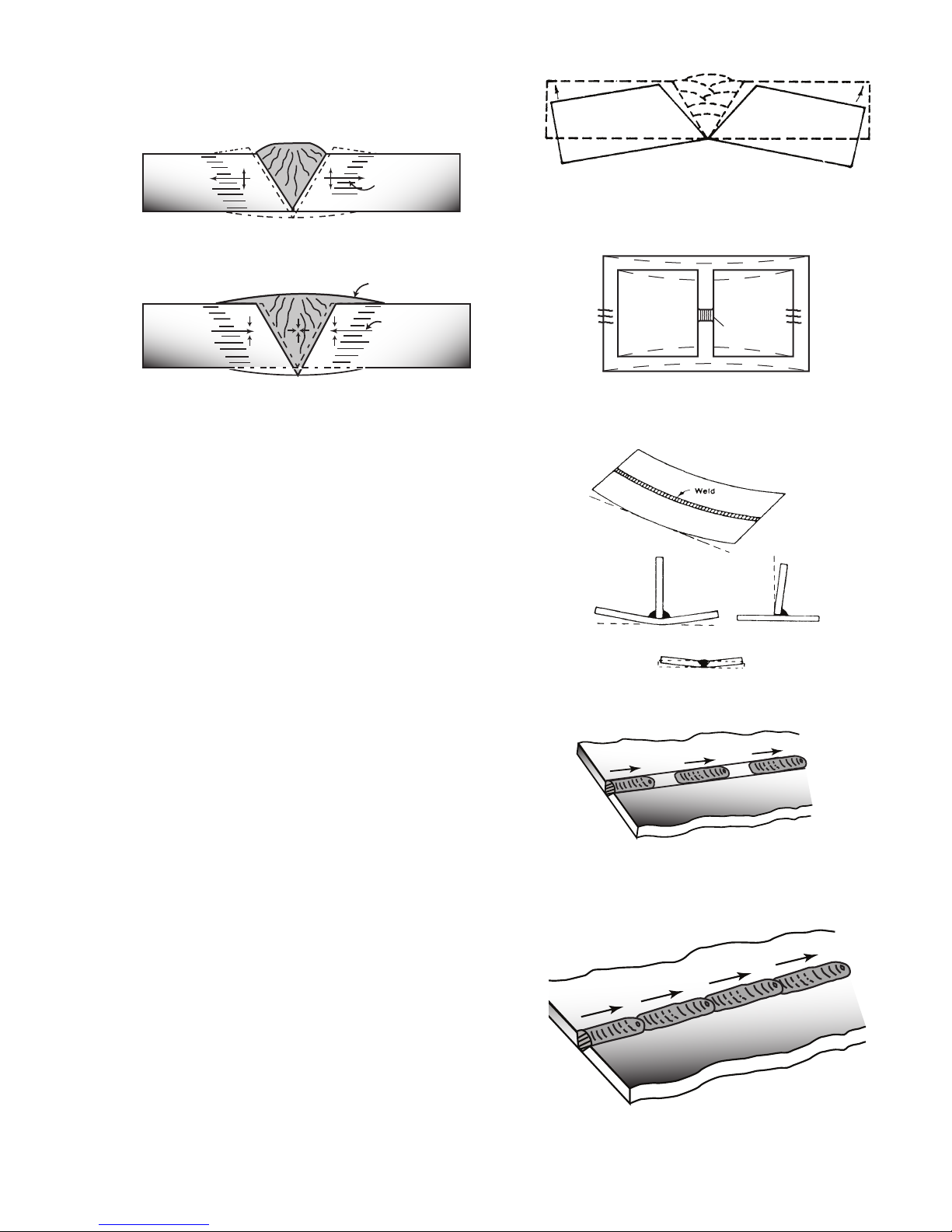
stresses (distortion), or the weld may crack, in any case, there
Art # A-07705_AB
Weld
Upsetting
Art # A-07706_AC
Weld
Permanent Upset
Contraction
with tension
Art # A-07708
Preheat
Dotted lines show effect if no preheat is used
Art # A-07710_AB
will remain "locked-up" stresses in the job. Figures 4-19 and
4- 20 illustrate how distortion is created.
ET 220I AC/DC
Hot
Hot
Figure 4-19: Parent Metal Expansion
Figure 4-20: Parent Metal Contraction
Overcoming Distortion Effects
There are several methods of minimizing distortion effects.
A. Peening
This is done by hammering the weld while it is still hot. The
weld metal is flattened slightly and because of this the tensile
stresses are reduced a little. The effect of peening is relatively
shallow, and is not advisable on the last layer.
B. Distribution of Stresses
Distortion may be reduced by selecting a welding sequence
which will distribute the stresses suitably so that they tend
to cancel each other out. See Figures 4-20 through 4-23 for
various weld sequences. Choice of a suitable weld sequence
is probably the most effective method of overcoming distortion, although an unsuitable sequence may exaggerate it.
Simultaneous welding of both sides of a joint by two welders
is often successful in eliminating distortion.
C. Restraint of Parts
Forcible restraint of the components being welded is often
used to prevent distortion. Jigs, positions, and tack welds are
methods employed with this in view.
D. Presetting
It is possible in some cases to tell from past experience or to
find by trial and error (or less frequently, to calculate) how much
distortion will take place in a given welded structure. By correct
pre-setting of the components to be welded, constructional
stresses can be made to pull the parts into correct alignment.
A simple example is shown in Figure 4-21.
E. Preheating
Suitable preheating of parts of the structure other than the
area to be welded can be sometimes used to reduce distortion. Figure 4-22 shows a simple application. By removing the
heating source from b and c as soon as welding is completed,
the sections b and c will contract at a similar rate, thus reduc-
ing distortion.
Manual 0-5346 BASIC WELDING GUIDE
Expansion with
compression
Cool
Art # A-07707
Figure 4-21: Principle of Presetting
B
Weld
C
Preheat
Figure 4-22: Reduction of Distortion by Preheating
Art # A-07709
Figure 4-23: Examples of Distortion
1
2
Block Sequence.
The spaces between the welds are
filled in when the welds are cool.
3
Figure 4-24: Welding Sequence
1
2
3
4
Figure 4-25: Step back Sequence
4-7
Page 54
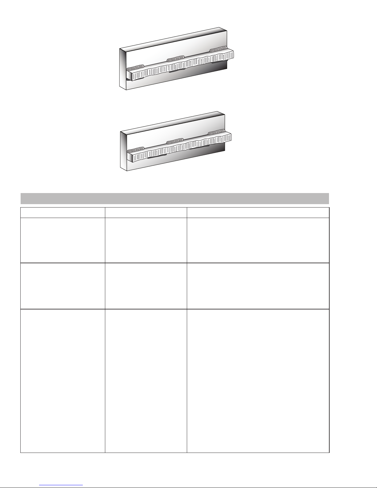
ET 220I AC/DC
Art # A-07428_AB
Figure 4-26: Chain Intermittent Welding
Art # A-07713_AB
Figure 4-27: Staggered Intermittent Welding
4.02 Stick (SMAW) Welding Troubleshooting
FAULT CAUSE REMEDY
1 Welding current varying ARC FORCE parameter is
set at a value that causes
the welding current to vary
excessively with the arc
length.
2 A gap is left by failure of the
weld metal to fill the root of
the weld.
3 Non-metallic particles are
trapped in the weld metal.
A Welding current too low A Increase welding current.
B Electrode too large for
joint.
C Insufficient gap. C Allow wider gap.
A Non-metallic particles may
be trapped in undercut
from previous run.
B Joint preparation too
restricted.
C Irregular deposits allow
slag to be trapped.
Reduce the ARC FORCE parameter until welding
current is reasonably constant while prohibiting
the electrode from sticking to the work piece
when you “dig” the electrode into the workpiece.
B Use smaller diameter electrode.
A If a bad undercut is present clean slag bout and
cover with a run from a smaller gauge electrode.
B Allow for adequate penetration and room for
cleaning out the slag.
C If very bad, chip or grind out irregularities.
D Lack of penetration with
slag trapped beneath weld
bead.
E Rust or mill scale is
D Use smaller electrode with sufficient current to
give adequate penetration. Use suitable tools to
remove all slag from comers.
E Clean joint before welding.
preventing full fusion.
F Wrong electrode for
position in which welding
is done.
BASIC WELDING GUIDE Manual 0-5346
4-8
F Use electrodes designed for position in which
welding is done, otherwise proper control of slag
is difficult.
Page 55
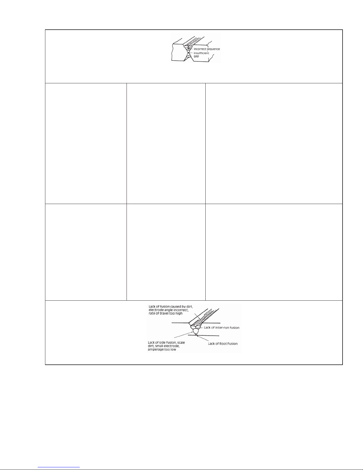
Art: A-04971
Figure 1: Example of insufficient gap or incorrect sequence
ET 220I AC/DC
4 A groove has been formed
in the base metal adjacent
to the toe of a weld and has
not been filled by the weld
metal (undercut).
5 Portions of the weld run
do not fuse to the surface
of the metal or edge of the
joint.
A Welding current is too
A Reduce welding current.
high.
B Welding arc is too long. B Reduce the length of the welding arc.
C Angle of the electrode is
incorrect.
D Joint preparation does not
allow correct electrode
C Electrode should not be inclined less than 45° to
the vertical face.
D Allow more room in joint for manipulation of the
electrode.
angle.
E Electrode too large for
E Use smaller gauge electrode.
joint.
F Insufficient deposit time at
edge of weave.
A Small electrodes used on
F Pause for a moment at edge of weave to allow
weld metal buildup.
A Use larger electrodes and preheat the plate.
heavy cold plate.
B Welding current is too low. B Increase welding current.
C Wrong electrode angle. C Adjust angle so the welding arc is directed more
into the base metal.
D Travel speed of electrode
is too high.
E Scale or dirt on joint
surface.
Figure 2: Example of Lack of Fusion
D Reduce travel speed of electrode.
E Clean surface before welding.
Art: A-04972
Manual 0-5346 BASIC WELDING GUIDE
4-9
Page 56
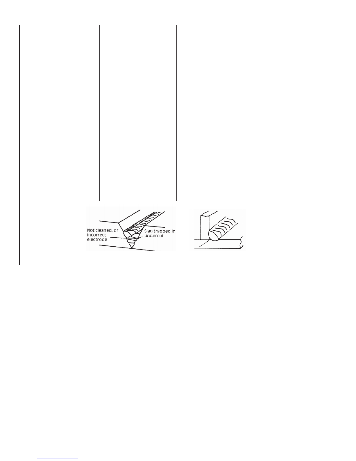
ET 220I AC/DC
6 Gas pockets or voids in
weld metal (porosity)
7 Crack occurring in
weld metal soon after
solidification commences
A High levels of sulphur in
steel.
A Use an electrode that is designed for high
sulphur steels.
B Electrodes are damp. B Dry electrodes before use.
C Welding current is too
C Reduce welding current.
high.
D Surface impurities such as
D Clean joint before welding.
oil, grease, paint, etc.
E Welding in a windy
E Shield the weld area from the wind.
environment.
F Electrode damaged ie flux
coating incomplete.
F Discard damaged electrodes and only use
electrodes with a complete flux coating.
A Rigidity of joint. A Redesign to relieve weld joint of severe stresses
or use crack resistance electrodes.
B Insufficient throat
thickness.
B Travel slightly slower to allow greater build up in
throat.
C Weld current is too high. C Decrease welding current.
Art: A-04973
Figure 3: Example of Slag Inclusion
Table 4-1: Welding Problems SMAW (Stick)
BASIC WELDING GUIDE Manual 0-5346
4-10
Page 57
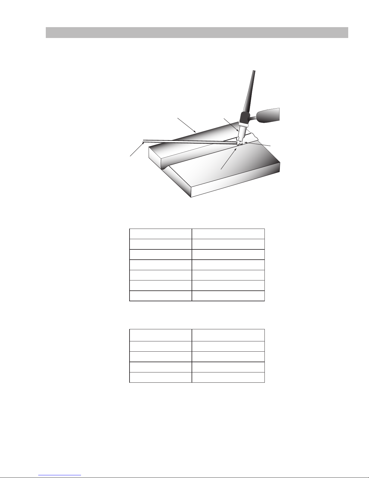
ET 220I AC/DC
Welds Made With or Without
Addition of Filler Metal
Work Piece
Can Be Any Commercial
Metal
Gas Cup
Either Ceramic,
High-lmpact or
Water Cooled
Metal
Inert Gas
Shields Electrode
and Weld Puddle
Tungsten Electrode
Non-Consumable
Art # A-09658_AC
4.03 TIG (GTAW) Basic Welding Technique
Gas Tungsten Arc Welding (GTAW) or TIG (Tungsten Inert Gas) as it is commonly referred to, is a welding process in which fusion is
produced by an electric arc that is established between a single tungsten (non-consumable) electrode and the work piece. Shielding is
obtained from a welding grade shielding gas or welding grade shielding gas mixture which is generally Argon based. A filler metal may
also be added manually in some circumstances depending on the welding application.
Tungsten Electrode Current Ranges
Guide for Selecting Filler Wire Diameter
Figure 4-28: TIG Welding Application Shot
Electrode Diameter DC Current (Amps)
0.040” (1.0mm) 30-60
1/16” (1.6mm) 60-115
3/32” (2.4mm) 100-165
1/8” (3.2mm) 135-200
5/32” (4.0mm) 190-280
3/16” (4.8mm) 250-340
Table 4-2: Current Ranges for Various Tungsten Electrode Sizes
Filler Wire Diameter DC Current Range (Amps)
1/16” (1.6mm) 20-90
3/32” (2.4mm) 65-115
1/8” (3.2mm) 100-165
3/16” (4.8mm) 200-350
Table 4-3: Filler Wire Selection Guide
Manual 0-5346 BASIC WELDING GUIDE
4-11
Page 58

ET 220I AC/DC
Tungsten Electrode Types
Electrode Type
(Ground Finish)
Thoriated 2%
Zirconated 1%
DC welding of mild steel, stainless steel
and copper
High quality AC welding of aluminium,
magnesium and their alloys.
AC & DC welding of mild steel, stainless
Ceriated 2%
steel, copper, aluminium, magnesium
and their alloys
TIG Welding Filler Rods
Welding Application Features Colour Code
Excellent arc starting, Long life, High
current carrying capacity
Red
Self cleaning, Long life, Maintains
balled end, High current carrying
White
capacity.
Longer life, More stable arc, Easier
starting, Wider current range,
Grey
Narrower more concentrated arc.
Table 4-4: Tungsten Electrode Types
AWS Std Type/Application
ER70S-4
ER70S-6
For mild-medium strength steels.
Pipes, tubing, roll cages, etc.
ER70S-2
ER80S-B2
ER90S-B3
For welding of high strength
Cr-Mo steels used at elevated
temperatures.
Base Metal
Thickness
0.040”
1.0mm
0.045”
1.2mm
1/16”
1.6mm
1/8”
3.2mm
DC Current for
Mild Steel
35-45
40-50
45-55
50-60
60-70
70-90
80-100
90-115
ER308L
ER309L
For stainless steels. Stainless pipes,
tubing, architectural uses, etc.
ER316L
R4043 For stainless steels. Stainless pipes,
tubing, architectural uses, etc.
R5356 For cast and wrought aluminium
alloys.
Table 4-5: TIG Welding Filler Rods
DC Current for
Stainless Steel
20-30
25-35
30-45
35-50
40-60
50-70
65-85
90-110
Tungsten
Electrode
Diameter
0.040”
1.0mm
0.040”
1.0mm
1/16”
1.6mm
1/16”
1.6mm
Filler Rod
Diameter (if
required)
1/16”
1.6mm
1/16”
1.6mm
1/16”
1.6mm
3/32”
2.4mm
Argon Gas Flow
Rate Litres/min
5-7 Butt/Corner
5-7 Butt/Corner
7 Butt/Corner
7 Butt/Corner
Joint Type
Lap/Fillet
Lap/Fillet
Lap/Fillet
Lap/Fillet
3/16”
4.8mm
1/4”
6.4mm
BASIC WELDING GUIDE Manual 0-5346
4-12
115-135
140-165
160-175
170-200
100-125
125-150
135-160
160-180
3/32”
2.4mm
1/8”
3.2mm
Table 4-6: Welding Rate
1/8”
3.2mm
5/32”
4.0mm
10 Butt/Corner
10 Butt/Corner
Lap/Fillet
Lap/Fillet
Page 59

ET 220I AC/DC
TIG Welding is generally regarded as a specialised process that requires operator competency. While many of the principles outlined in the previous Arc Welding section are applicable a comprehensive outline of the TIG Welding process is outside the scope of
this Operating Manual. For further information please refer to www.esab.com or contact ESAB.
4.04 TIG (GTAW) Welding Problems
FAULT CAUSE REMEDY
1 Excessive bead build up or
poor penetration or poor
fusion at edges of weld.
2 Weld bead too wide and
flat or undercut at edges
of weld or excessive burn
through.
3 Weld bead too small or
insufficient penetration or
ripples in bead are widely
spaced apart.
4
Weld bead too wide or
excessive bead build up or
excessive penetration in
butt joint.
5 Uneven leg length in fillet
joint
6 Electrode melts or oxidises
when an arc is struck.
Welding current is too
low
Welding current is too
Increase weld current and/or faulty joint
preparation.
Decrease weld current.
high
Travel speed too fast Reduce travel speed.
Travel speed too slow Increase travel speed.
Wrong placement of
Re-position filler rod.
filler rod
A Torch lead connected
to positive welding
A Connect torch lead to negative welding
terminal.
terminal.
B No gas flowing to
welding region.
C Torch is clogged with
B Check the gas lines for kinks or breaks
and gas cylinder contents.
C Clean torch.
dust or dirt.
D Gas hose is cut. D Replace gas hose.
E Gas passage contains
impurities.
E Disconnect gas hose from the rear of
Power Source then raise gas pressure
and blow out impurities.
F Gas regulator turned
F Turn on.
off.
G The electrode is too
small for the welding
G Increase electrode diameter or reduce the
welding current.
current.
H Power source is set for
Stick welding.
Manual 0-5346 BASIC WELDING GUIDE
H Set Power Source to a GTAW operating
mode.
4-13
Page 60

ET 220I AC/DC
FAULT CAUSE REMEDY
7 Dirty weld pool A Electrode contaminated
by contact with work
piece or filler rod
material.
B Work piece surface has
foreign material on it.
C Gas contaminated with
air.
8 Poor weld finish Inadequate shielding
gas.
9 Arc start is not smooth. A Tungsten electrode
is too large for the
welding current.
B The wrong electrode
is being used for the
welding job.
C Gas flow rate is too
high.
A Clean the electrode by grinding off the
contaminates.
B Clean surface.
C Check gas lines for cuts and loose fitting
or change gas cylinder.
Increase gas flow or check gas line for
gas flow problems.
A Select the right size tungsten electrode.
Refer to Table 4-3 ESAB Tungsten
Electrode Selection Chart.
B Select the right tungsten electrode
type. Refer to Table 4-5 ESAB Tungsten
Electrode Selection Chart.
C Select the right rate for the welding job.
Refer to Table 4-7.
10 Arc flutters during TIG
welding.
D Incorrect shielding gas
is being used.
E Poor work clamp
connection to work
piece.
Tungsten electrode
is too large for the
welding current.
Table 4-7
D Select the right shielding gas.
E Improve connection to work piece.
Select the right size tungsten electrode.
Refer to Table 4-3 ESAB Tungsten
Electrode Selection Chart.
BASIC WELDING GUIDE Manual 0-5346
4-14
Page 61
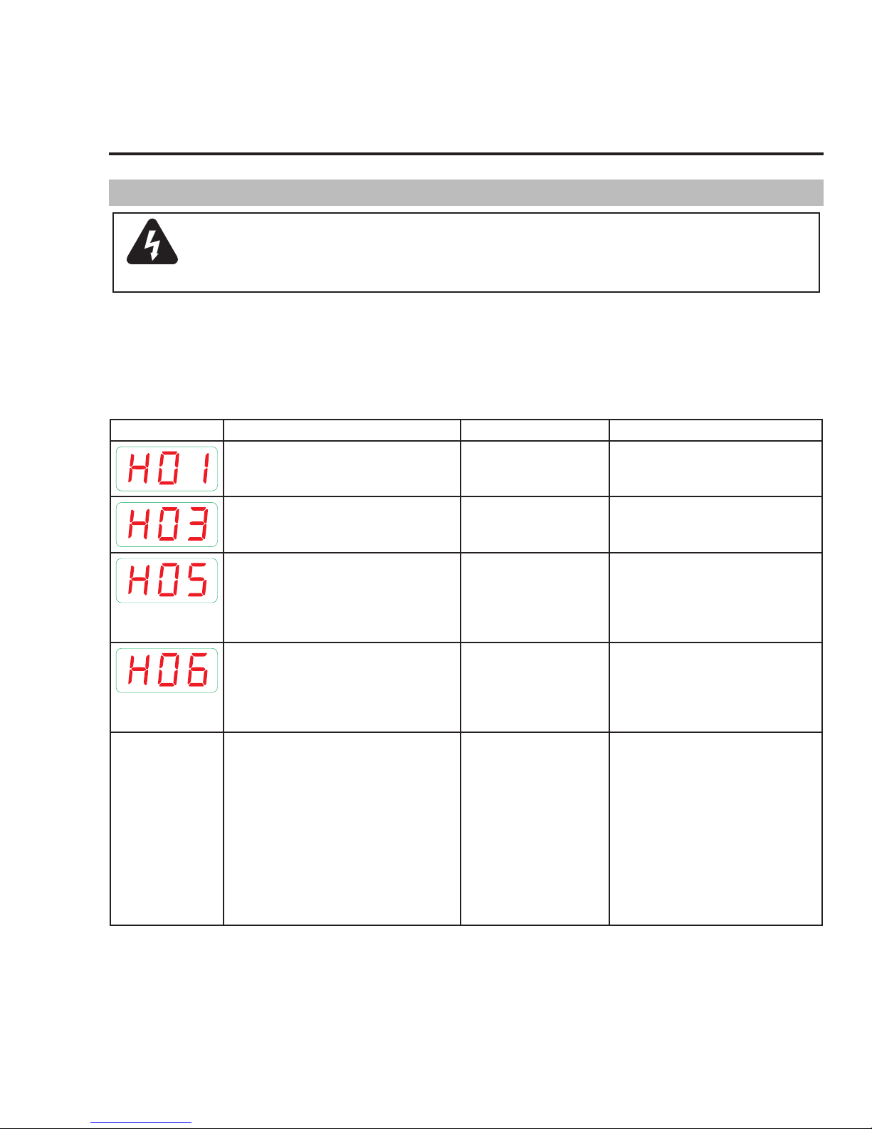
ET 220I AC/DC
SECTION 5:
POWER SOURCE PROBLEMS AND ROUTINE SERVICE
REQUIREMENTS
5.01 Basic Troubleshooting
WARNING
There are extremely dangerous voltage and power levels present inside this product. Do not attempt to
open or repair unless you are a qualified electrical tradesperson and you have had training in power measurements and troubleshooting techniques..
If major complex subassemblies are faulty, then the Welding Power Source must be returned to an accredited ESAB Service Provider for
repair. The basic level of troubleshooting is that which can be performed without special equipment or knowledge. Refer also to section
4 for solving welding problems.
Information Messages
If a message has been displayed, the power source may only function to a limited capacity. The cause of the condition must be remedied as soon as possible.
Message Code Note Cause Possible Remedy
Mains Supply Under Voltage Mains Supply Voltage is
too low
Check Mains Supply Voltage
No Display
Fans Fan Fault Have an Accredited ESAB Service
Provider check the power source.
EEProm checksum error Communication with
EEProm is faulty
EEProm read / write error Communication with
EEProm is faulty
The fuse protects the small control transformer that produces the internal supply
for the PCBs. A blown fuse might be the
result of turning the on-off switch to often
in a very short time. DO NOT flip the on-off
switch more than two times within a one
second period. This may result in no display on the machine even while turned on.
Table 5-1: Information Messages
Turning the machine off
too many times in a short
period.
Switch machine off, then back on.
Perform a master reset. If the problem
continues have an Accredited ESAB
Service Provider check the power
source.
Switch machine off, then back on.
Perform a master reset. If the problem
continues have an Accredited ESAB
Service Provider check the power
source.
Turn the machine OFF for two minutes
then switch ON again. If still no
display shows it is likely the fuse is
blown and needs to be replaced. The
fuse on the relay board is a 2.5A/500V
(slow blowing) 6.3mm x 32mm.
Note: When switching the machine
off and on again, wait 2-3 seconds
between each switch. For example
switch off, wait 3 seconds, switch on
again.
Manual 0-5346 POWER SOURCE PROBLEMS AND ROUTINE SERVICE REQUIREMENTS
5-1
Page 62
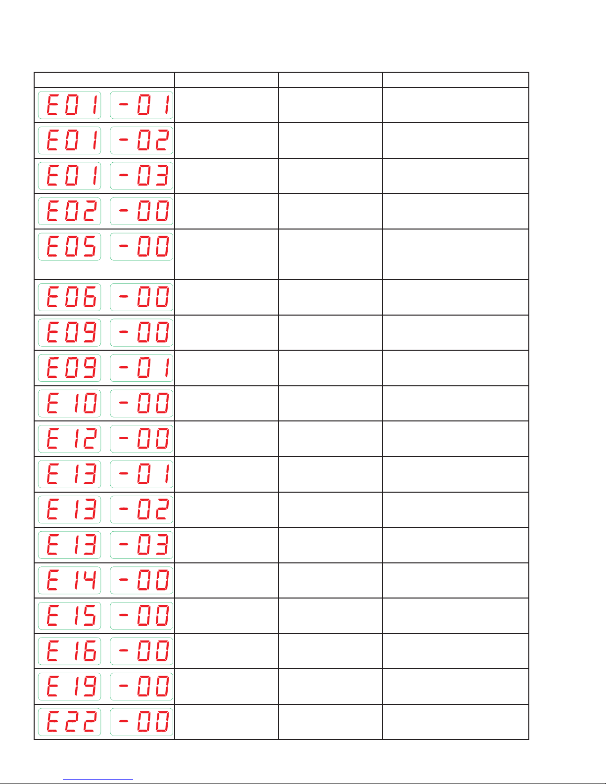
ET 220I AC/DC
Error Messages
If a message has been displayed, have an Accredited ESAB Service Provider check the power source.
Message Code Error Cause Possible Remedy
Thermal Overload of
Output Diodes
Duty Cycle has been
exceeded
Leave the power source switched ON
and allow it to cool.
Thermal Overload of
Primary Module
Thermal Overload of
Transformer
Mains Supply Over Voltage
Water Pump (in water
cooled operation)
Torch Monitor (in gas
cooled operation)
Secondary Over Voltage Initial Voltage is too high Have an Accredited ESAB Service
Voltage Detection Voltage Detection Error Have an Accredited ESAB Service
Voltage Detection plug
socket
Torch / Remote Control Remote Control, Torch or
Duty Cycle has been
exceeded
Duty Cycle has been
exceeded
Mains Supply Voltage is
too high
Defective connection
cable or water cooler
Water cooled GTAW torch
connected
Voltage Detection Error in
module 2
connections defective
Leave the power source switched ON
and allow it to cool.
Leave the power source switched ON
and allow it to cool.
Check Mains Supply Voltage
Check the Net Connection water
cooler cable and the water cooler.
Use a gas cooled torch
Provider check the power source
Provider check the power source
Have an Accredited ESAB Service
Provider check the power source
Check or replace Torch or Remote
Control
Power Section Fault Power Section start up
Fault
Temperature Sensor
Secondary Diode
Temperature Sensor
Primary Module
Temperature Sensor
Transformer
Internal Supply Voltage Internal Supply Voltage
Current Detection Current Detection Fault Have an Accredited ESAB Service
Shutdown due to over
current
HF Ignition Faulty HF Ignition Faulty Have an Accredited ESAB Service
Mains Supply Under
Voltage
Defective Thermal Sensor Have an Accredited ESAB Service
Defective Thermal Sensor Have an Accredited ESAB Service
Defective Thermal Sensor Have an Accredited ESAB Service
Fault
Mains Supply Current is
too high
Mains Supply Voltage is
too low
Have an Accredited ESAB Service
Provider check the power source
Provider check the power source
Provider check the power source
Provider check the power source
Have an Accredited ESAB Service
Provider check the power source
Provider check the power source
Have an Accredited ESAB Service
Provider check the power source
Provider check the power source
Check Mains Supply Voltage
POWER SOURCE PROBLEMS AND ROUTINE SERVICE REQUIREMENTS Manual 0-5346
5-2
Page 63
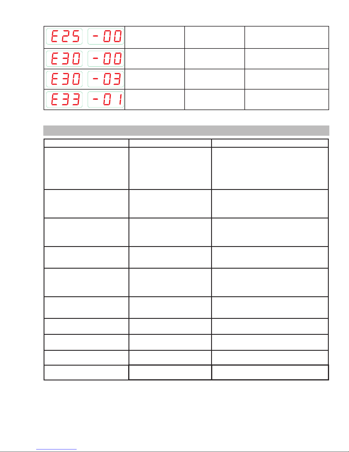
ET 220I AC/DC
The Electrode is shorted
to work piece when machine is turned ON
Configuration Error Defective PCB, incorrect
Control Panel identification
Power Module Power Module not sym-
VRD defective, or short
circuit between torch and
work piece
system software
Control Panel identification error
metrical
Switch OFF and ON the power source
to clear the error code
Have an Accredited ESAB Service
Provider check the power source
Have an Accredited ESAB Service
Provider check the power source
Have an Accredited ESAB Service
Provider check the power source
Table 5-2: Error Message
5.02 Power Source Problems
FAULT CAUSE REMEDY
1 Mains supply voltage is ON,
Control panel LED's are
illuminated however unit will
not commence welding when
the torch trigger switch is
depressed.
2 Mains supply voltage is
ON. Indicator light is not lit
and welding arc cannot be
established.
3 Error Code E01 is displayed
and unit will not commence
welding when the torch trigger
switch is depressed.
4 Welding output continues when
torch trigger released
5 Welding output voltage is
present when the torch trigger
switch is depressed but arc
cannot be established.
6 Welding output voltage is not
present when torch trigger
depressed
7 TIG electrode melts when
arc is struck.
8 Arc flutters during TIG
welding.
9 No HF output in HF mode HF Circuit faulty Have an Accredited ESAB Service Provider
10 Error Code is displayed Refer to the error code list,
A
Power source is not in the
correct mode of operation.
B
Faulty torch trigger.
A
Primary control fuse is blown.
Broken connection in primary
B
circuit.
Duty cycle of power source has
been exceeded.
A
Trigger mode selection is in 4T
(LATCH) mode
B
Torch trigger leads shorted
Poor or no work lead contact. Clean work clamp area and ensure good
Faulty trigger switch / lead Repair or replace Torch / trigger lead
TIG torch is connected to
the Worklead terminal.
Tungsten electrode is too
large for the welding current.
section 3.16
A
Set the power source to the correct mode of
operation with the process selection switch.
Repair or replace torch trigger switch/lead.
B
A
Replace primary control fuse.
B
Have an Accredited ESAB Service Provider
check primary circuit.
Leave the power source switched ON and
allow it to cool. Note that fault indicator must
be extinguished prior to commencement of
welding.
A
Change to 2T (NORMAL) mode
B
Repair or replace Torch / trigger lead
electrical contact.
Connect the TIG torch to the Electrode
terminal.
Select the correct size of tungsten
electrode.
check HF circuit.
Refer to the error code list, section 3.16
Table 5-3: Power Source Problem
Manual 0-5346 POWER SOURCE PROBLEMS AND ROUTINE SERVICE REQUIREMENTS
5-3
Page 64
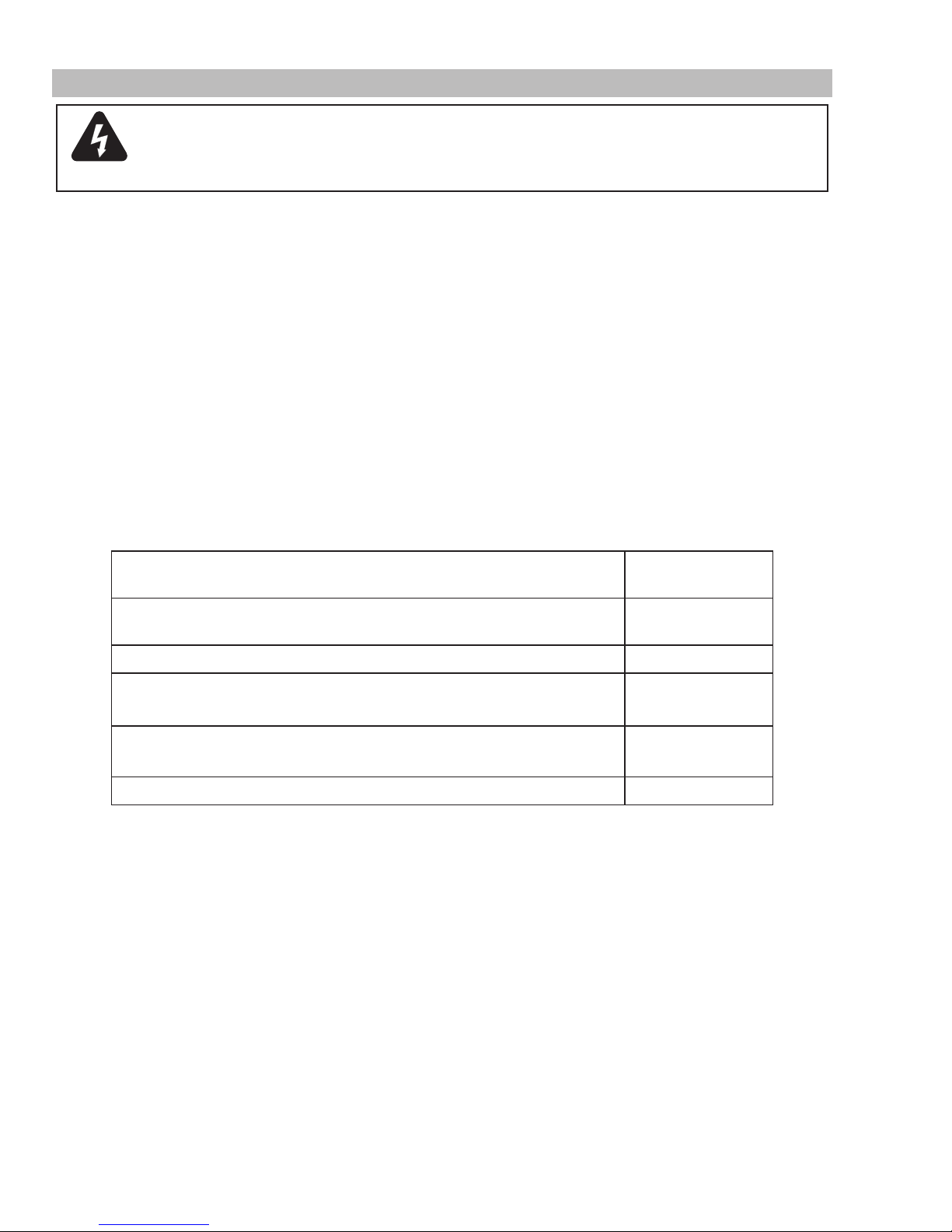
ET 220I AC/DC
5.03 Routine Service and Calibration Requirements
WARNING
There are extremely dangerous voltage and power levels present inside this Inverter Power Source. Do
not attempt to open or repair unless you are an accredited ESAB Service Provider. Disconnect the Welding
Power Source from the Mains Supply Voltage before disassembling.
Routine Inspection, Testing & Maintenance
The inspection and testing of the power source and associated accessories shall be carried out by a licensed electrician. Safety in
Welding and Allied Processes-Part 2 Electrical. This includes an insulation resistance test and an earthing test to ensure the integrity of
the unit is compliant with ESAB original specifications.
A. Testing Schedule
1. For transportable equipment, at least once every 3 months; and
2. For fixed equipment, at least once every 12 months.
The owners of the equipment shall keep a suitable record of the periodic tests and a system of tagging, including the date of the
most recent inspection.
A transportable power source is deemed to be any equipment that is not permanently connected and fixed in the position in which
it is operated.
B. Insulation Resistance
Minimum insulation resistance for in-service ESAB Inverter Power Sources shall be measured at a voltage of 500V between the parts
referred to in Table 5-2 below. Power sources that do not meet the insulation resistance requirements set out below shall be withdrawn
from service and not returned until repairs have been performed such that the requirements outlined below are met.
Components to be Tested
Input circuit (including any connected control circuits) to welding circuit
(including any connected control circuits)
All circuits to exposed conductive parts
Welding circuit (including any connected control circuits) to any auxiliary
circuit which operates at a voltage exceeding extra low voltage
Welding circuit (including any connected control circuits) to any auxiliary
circuit which operates at a voltage not exceeding extra low voltage
Separate welding circuit to separate welding circuit
Table 5-4: Minimum Insulation Resistance Requirements: ESAB Inverter Power Sources
C. Earth Grounding
The resistance shall not exceed 1Ω between any metal of a power source where such metal is required to be Earth Ground, and -
1. The Earth Ground terminal of a fixed power source; or
2. The Earth Ground terminal of the associated plug of a transportable power source
Note that due to the dangers of stray output currents damaging fixed wiring, the integrity of fixed wiring supplying ESAB welding
power sources should be inspected by a licensed electrical worker in accordance with the requirements below -
1. For outlets/wiring and associated accessories supplying transportable equipment - at least once every 3 months; and
2. For outlets/wiring and associated accessories supplying fixed equipment - at least once every 12 months.
D. General Maintenance Checks
Minimum Insulation
Resistance (MΩ)
5
2.5
10
1
1
Welding equipment should be regularly checked by an accredited ESAB Service Provider to ensure that:
1. Flexible cord is of the multi-core tough rubber or plastic sheathed type of adequate rating, correctly connected and in good
condition.
2. Welding terminals are in suitable condition and are shrouded to prevent inadvertent contact or short circuit.
3. The Welding System is clean internally, especially from metal filing, slag, and loose material.
POWER SOURCE PROBLEMS AND ROUTINE SERVICE REQUIREMENTS Manual 0-5346
5-4
Page 65
ET 220I AC/DC
E. Accessories
Accessory equipment, including output leads, electrode holders, torches, wire feeders and the like shall be inspected at least monthly
by a competent person to ensure that the equipment is in a safe and serviceable condition. All unsafe accessories shall not be used.
F. Repairs
If any parts are damaged for any reason, it is recommended that replacement be performed by an accredited ESAB Service Provider.
Power Source Calibration
A. Schedule
Output testing of all ESAB Inverter Power Sources and applicable accessories shall be conducted at regular intervals to ensure they
fall within specified levels. Calibration intervals shall be as outlined below -
1. For transportable equipment, at least once every 3 months; and
2. For fixed equipment, at least once every 12 months.
If equipment is to be used in a hazardous location or environments with a high risk of electrocution as outlined in EN 60974-1, then
the above tests should be carried out prior to entering this location.
B. Calibration Requirements
Where applicable, the tests outlined in Table 5-3 below shall be conducted by an accredited ESAB service provider.
Testing Requirements
Output current (A) to be checked to ensure it falls within applicable ESAB power source specifications
Output Voltage (V) to be checked to ensure it falls within applicable ESAB power source specifications
Accuracy of digital meters to be checked to ensure it falls within applicable ESAB power source
specifications
Table 5-5: Calibration Parameters
Periodic calibration of other parameters such as timing functions are not required unless a specific fault has been identified.
C. Calibration Equipment
All equipment used for Power Source calibration shall be in proper working condition and be suitable for conducting the measurement
in question. Only test equipment with valid calibration certificates (NATA certified laboratories) shall be utilized.
5.04 Cleaning the Welding Power Source
WARNING
There are dangerous voltage and power levels present inside this product. Do not attempt to open or
repair unless you are a qualified electrical tradesperson. Disconnect the Welding Power Source from the
Mains Supply Voltage before disassembling.
To clean the Welding Power Source, open the enclosure and use a vacuum cleaner to remove any accumulated dirt, metal filings, slag
and loose material. Keep the shunt and lead screw surfaces clean as accumulated foreign material may reduce the welders output
welding current.
Manual 0-5346 POWER SOURCE PROBLEMS AND ROUTINE SERVICE REQUIREMENTS
5-5
Page 66

ET 220I AC/DC
This Page Intentionally Blank
POWER SOURCE PROBLEMS AND ROUTINE SERVICE REQUIREMENTS Manual 0-5346
5-6
Page 67

SECTION 6:
KEY SPARE PARTS
This Page Intentionally Blank.
See next two pages.
ET 201I AC/DC
0-5346 KEY SPARE PARTS
6-1
Page 68
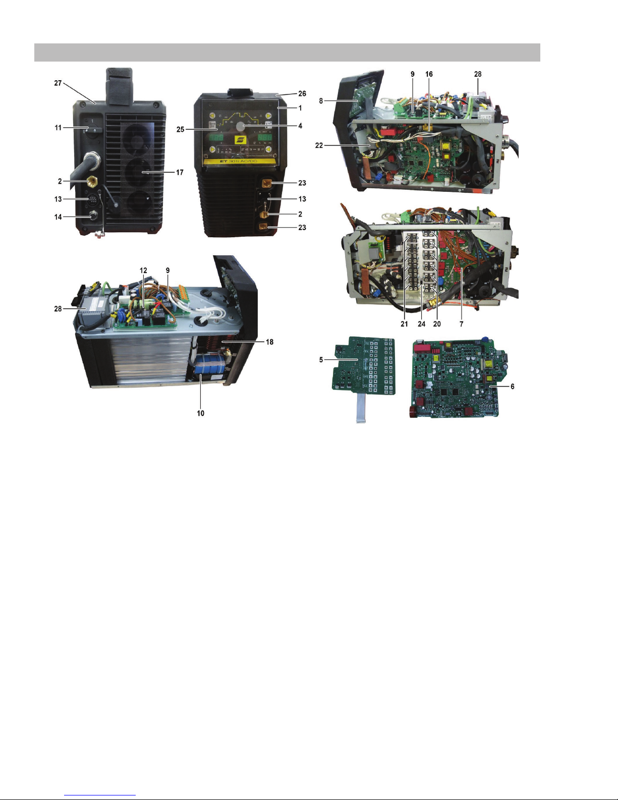
ET 201I AC/DC
A-12885_AB
6.01 Key Spare Parts
Figure 6-1: Spare Parts
KEY SPARE PARTS 0-5346
6-2
Page 69

ET 220i AC/DC Spare Parts
Item Part Number Description
1
2
2
4
5
6
7
8
9
10
11
12
13
14
13
16
17
18
20
21
22
23
24
25
26
27
28
W7006300 Clear Control Panel Cover
W7006301 Gas Outlet, Front Panel
W7006301 Gas Inlet, Rear Panel
W7006500 Knob, Control
W7006323 PCB Secondary Rectifier
W7006433 PCB Control
W7006434 PCB Primary Inverter
W7006307 PCB, Display
W7006427 REL02
W7006326 Transformer, Inverter
W7006439 Switch, On/Off
W7006426 Rectifier, Bridge, Mains Supply
W7006314 Cable Assy, 8 Pin Remote
W7006431 Cable Assy, 4 Pin CAN
667.8377.0 Cable Assy, 14 Pin Remote
W7006315 Solenoid 24VDC
W7006316 Fan 12VDC
W7006317 Inductor HF
W7006319 IGBT
W7006740 Diode, Output
W7006425 HF Filter
W7006430 Panel Mount Dinse Socket 50mm
W6000000 Thermal Sensor
W7006441 Panel, Control (User Interface)
W7006429. Panel, Front
W7006440 Panel, Rear
W7006428 Transformer, Control
2
Table 6-1: Spare Parts
ET 201I AC/DC
0-5346 KEY SPARE PARTS
6-3
Page 70

ET 201I AC/DC
This Page Intentionally Blank
KEY SPARE PARTS 0-5346
6-4
Page 71
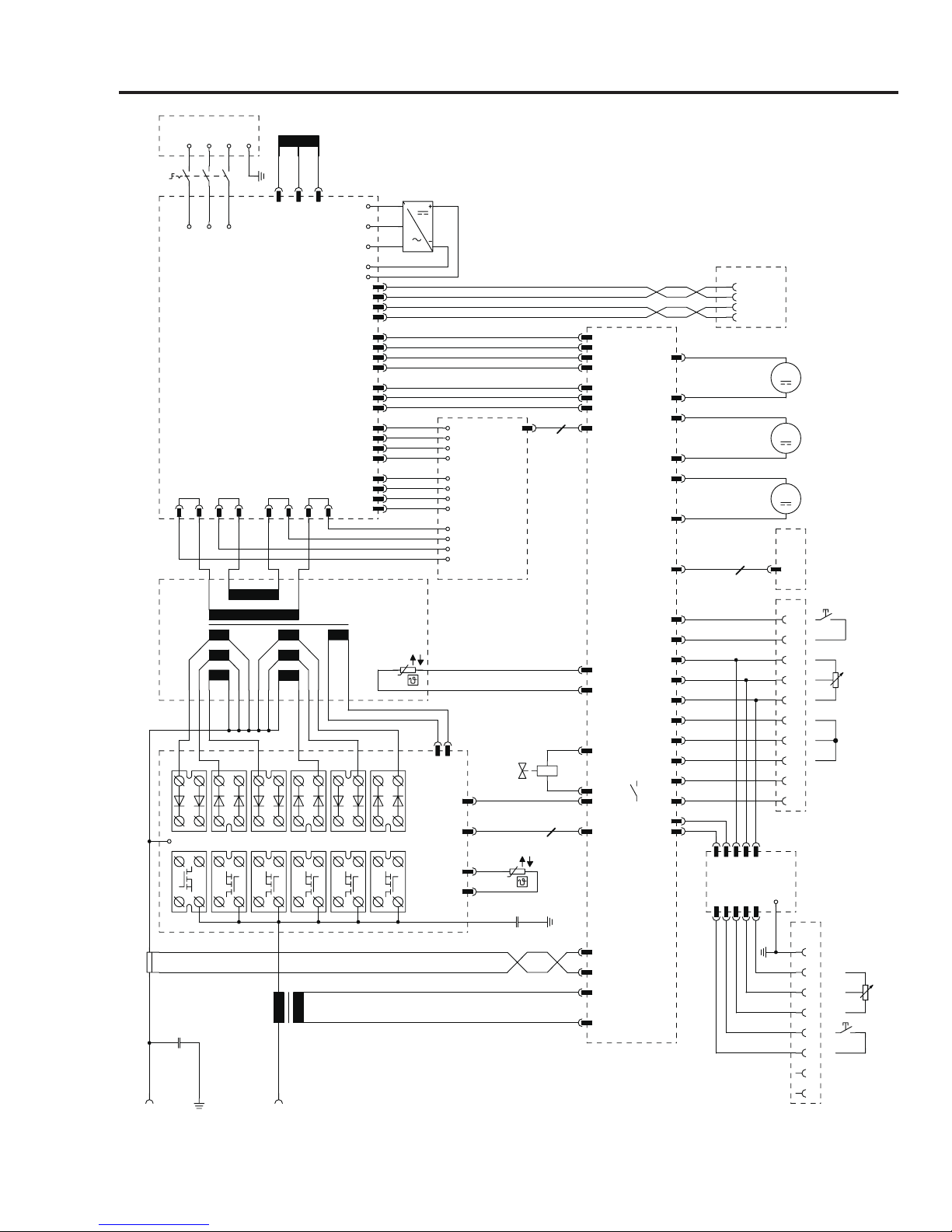
ET 220I AC/DC
Art # A-12883
20
9
14
GND
+VCC
CAN_L
CAN_H
+
-
+10V
0-10V
GND
GND
0-10V
+10V
PEL1
LP4
LP1
X2 X3
X1 X5
X8/1
X8/2
F1
C1
X7/2
X7/1
R1
X11/1
X11/2
M1
M
X13/1
X13/2
M2
M
X15/1
X15/2
M3
M
X4
A6
X3
X17/1 1
X17/2 2
X17/3 3
X17/4 4
X17/5 5
X17/6
6
X17/7 7
X17/8 8
X17/9 9
X17/10 10
3
4
X5
X3
I1
2-Takt
2-stroke
I > 0
Kennung
extern
Y1
X12/2
X12/1
L1
2
1
X4
X1
L1T1L2T2L3
T3
Q1
L2 L3
LP2
LP3
~-
~
~+
A4
AC
AC
AC
3
LP5
LP6
A1
REL02
X1
A5
Mapro
X1/7
X1/8
X12/5
A2
DRV06
LP6
LP7
LP8
X3/2
X3/3
X3/4
braun
brown
weiß
white
schwarz
black
grau
gray
T1
A3
F2
X3/1
X3/2
A1
A7
LP1
X4/1
X5/1
X5/2
X5/3
460V
230V
0V
T2
TR4
TR2
TR1
TR3
C2
X2/3
A2
A8
E1
A10
E3
A12
X2/1
A3
A9
E2
A11
A13 A14 A15 A16 A17 A18
X6
2
3
5
7
6
I1
A19
X2/3
X2/4
X2/5
X14/2
X14/1
X1/1
X1/2
X1/3
X1/5
X1/4
X2/2
X2/1
1
X6/1
X6/2
4
8
X18/1
X18/2
X18/3
X18/4
X1/6
X1/5
X1/4
X1/3
X1/2
X1/1
LP5
X3/1
X9
X8
X7
X6
LP4
LP3
LP2
LP1
LP8
LP7
X10/1X4/1
X4/2 X10/2
X4/3 X10/3
APPENDIX A: CIRCUIT DIAGRAM OF ET 220i AC/DC
Manual 0-5346 APPENDIX
A-1
Page 72

ET 220I AC/DC
REVISION HISTORY
Cover Date Rev. Change(s)
05/07/15 AA Manual release
01/15/16 AB Updated 'Liftarc TIG' wording, Section 6 art, spart parts list and Appendix
art.
APPENDIX Manual 0-5346
A-2
Page 73

Page 74

ESAB subsidiaries and representative oces
Europe
AUSTRIA
ESAB Ges.m.b.H
Vienna-Liesing
Tel: +43 1 888 25 11
Fax: +43 1 888 25 11 85
BELGIUM
S.A. ESAB N.V.
Heist-op-den-Berg
Tel: +32 70 233 075
Fax: +32 15 257 944
BULGARIA
ESAB Kft Representative Oce
Soa
Tel/Fax: +359 2 974 42 88
THE CZECH REPUBLIC
ESAB VAMBERK s.r.o.
Vamberk
Tel: +420 2 819 40 885
Fax: +420 2 819 40 120
DENMARK
Aktieselskabet ESAB
Herlev
Tel: +45 36 30 01 11
Fax: +45 36 30 40 03
FINLAND
ESAB Oy
Helsinki
Tel: +358 9 547 761
Fax: +358 9 547 77 71
FRANCE
ESAB France S.A.
Cergy Pontoise
Tel: +33 1 30 75 55 00
Fax: +33 1 30 75 55 24
GERMANY
ESAB GmbH
Solingen
Tel: +49 212 298 0
Fax: +49 212 298 218
GREAT BRITAIN
ESAB Group (UK) Ltd
Waltham Cross
Tel: +44 1992 76 85 15
Fax: +44 1992 71 58 03
ESAB Automation Ltd
Andover
Tel: +44 1264 33 22 33
Fax: +44 1264 33 20 74
HUNGARY
ESAB Kft
Budapest
Tel: +36 1 20 44 182
Fax: +36 1 20 44 186
ITALY
ESAB Saldatura S.p.A.
Bareggio (Mi)
Tel: +39 02 97 96 8.1
Fax: +39 02 97 96 87 01
THE NETHERLANDS
ESAB Nederland B.V.
Amersfoort
Tel: +31 33 422 35 55
Fax: +31 33 422 35 44
NORWAY
AS ESAB
Larvik
Tel: +47 33 12 10 00
Fax: +47 33 11 52 03
POLAND
ESAB Sp.zo.o.
Katowice
Tel: +48 32 351 11 00
Fax: +48 32 351 11 20
PORTUGAL
ESAB Lda
Lisbon
Tel: +351 8 310 960
Fax: +351 1 859 1277
ROMANIA
ESAB Romania Trading SRL
Bucharest
Tel: +40 316 900 600
Fax: +40 316 900 601
RUSSIA
LLC ESAB
Moscow
Tel: +7 (495) 663 20 08
Fax: +7 (495) 663 20 09
SLOVAKIA
ESAB Slovakia s.r.o.
Bratislava
Tel: +421 7 44 88 24 26
Fax: +421 7 44 88 87 41
SPAIN
ESAB Ibérica S.A.
Alcalá de Henares (MADRID)
Tel: +34 91 878 3600
Fax: +34 91 802 3461
SWEDEN
ESAB Sverige AB
Gothenburg
Tel: +46 31 50 95 00
Fax: +46 31 50 92 22
ESAB international AB
Gothenburg
Tel: +46 31 50 90 00
Fax: +46 31 50 93 60
SWITZERLAND
ESAB AG
Dietikon
Tel: +41 1 741 25 25
Fax: +41 1 740 30 55
UKRAINE
ESAB Ukraine LLC
Kiev
Tel: +38 (044) 501 23 24
Fax: +38 (044) 575 21 88
North and South America
ARGENTINA
CONARCO
Buenos Aires
Tel: +54 11 4 753 4039
Fax: +54 11 4 753 6313
BRAZIL
ESAB S.A.
Contagem-MG
Tel: +55 31 2191 4333
Fax: +55 31 2191 4440
CANADA
ESAB Group Canada Inc.
Missisauga, Ontario
Tel: +1 905 670 02 20
Fax: +1 905 670 48 79
MEXICO
ESAB Mexico S.A.
Monterrey
Tel: +52 8 350 5959
Fax: +52 8 350 7554
USA
ESAB Welding & Cutting Products
Florence, SC
Tel: +1 843 669 44 11
Fax: +1 843 664 57 48
Asia/Pacific
AUSTRALIA
ESAB South Pacic
Archereld BC QLD 4108
Tel: +61 1300 372 228
Fax: +61 7 3711 2328
CHINA
Shanghai ESAB A/P
Shanghai
Tel: +86 21 2326 3000
Fax: +86 21 6566 6622
INDIA
ESAB India Ltd
Calcutta
Tel: +91 33 478 45 17
Fax: +91 33 468 18 80
INDONESIA
P.T. ESABindo Pratama
Jakarta
Tel: +62 21 460 0188
Fax: +62 21 461 2929
JAPAN
ESAB Japan
Tok yo
Tel: +81 45 670 7073
Fax: +81 45 670 7001
MALAYSIA
ESAB (Malaysia) Snd Bhd
USJ
Tel: +603 8023 7835
Fax: +603 8023 0225
SINGAPORE
ESAB Asia/Pacic Pte Ltd
Singapore
Tel: +65 6861 43 22
Fax: +65 6861 31 95
SOUTH KOREA
ESAB SeAH Corporation
Kyungnam
Tel: +82 55 269 8170
Fax: +82 55 289 8864
UNITED ARAB EMIRATES
ESAB Middle East FZE
Dubai
Tel: +971 4 887 21 11
Fax: +971 4 887 22 63
Africa
EGYPT
ESAB Egypt
Dokki-Cairo
Tel: +20 2 390 96 69
Fax: +20 2 393 32 13
SOUTH AFRICA
ESAB Africa Welding & Cutting Ltd
Durbanvill 7570 - Cape Town
Tel: +27 (0)21 975 8924
Distributors
For addresses and phone numbers
to our distributors in other countries, please visit our home page
www.esab.eu
www.esab.com
©2015 ESAB Welding and Cutting Products
Printed in China
 Loading...