

Page 1
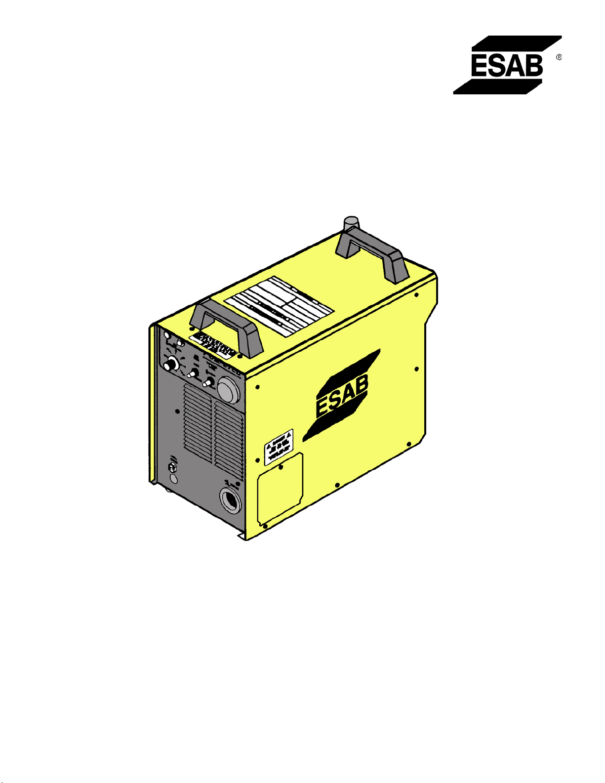
ESP-50
Plasma Arc Cutting Package
Instruction Manual
This manual provides installation and operation instructions for the following ESP-50 cutting packages starting with Serial No.: PxxJ403xxx
Consoles:
P/N 0558004371 - 208/230 V, 50/60 Hz, 1 or 3-phase
P/N 0558004372 - 400CE/460 V, 50/60 Hz, 3-phase, CE
0558004311 01 / 2006
Page 2

BE SURE THIS INFORMATION REACHES THE OPERATOR.
YOU CAN GET EXTRA COPIES THROUGH YOUR SUPPLIER.
CAUTION
These INSTRUCTIONS are for experienced operators. If you are not fully familiar with the
principles of operation and safe practices for arc welding and cutting equipment, we urge
you to read our booklet, “Precautions and Safe Practices for Arc Welding, Cutting, and
Gouging,” Form 52-529. Do NOT permit untrained persons to install, operate, or maintain
this equipment. Do NOT attempt to install or operate this equipment until you have read
and fully understand these instructions. If you do not fully understand these instructions,
contact your supplier for further information. Be sure to read the Safety Precautions before installing or operating this equipment.
USER RESPONSIBILITY
This equipment will perform in conformity with the description thereof contained in this manual and accompanying labels and/or inserts when installed, operated, maintained and repaired in accordance with the instructions provided. This equipment must be checked periodically. Malfunctioning or poorly maintained equipment
should not be used. Parts that are broken, missing, worn, distorted or contaminated should be replaced immediately. Should such repair or replacement become necessary, the manufacturer recommends that a telephone
or written request for service advice be made to the Authorized Distributor from whom it was purchased.
This equipment or any of its parts should not be altered without the prior written approval of the manufacturer.
The user of this equipment shall have the sole responsibility for any malfunction which results from improper
use, faulty maintenance, damage, improper repair or alteration by anyone other than the manufacturer or a service facility designated by the manufacturer.
2
Page 3

TABLE OF CONTENTS
SECTION TITLE PAGE
SECTION 1 SAFETY PRECAUTIONS ...................................................................................................................... 5
1.1 Safety - English ........................................................................................................................................ 5
1.2 Safety - Spanish ....................................................................................................................................... 9
1.3 Safety - French ......................................................................................................................................... 13
SECTION 2 DESCRIPTION .......................................................................................................................................... 17
2.1 General ....................................................................................................................................................... 17
2.2 Scope .......................................................................................................................................................... 17
2.3 Packages Available ................................................................................................................................. 17
2.4 Specifications ........................................................................................................................................... 17
2.5 Ordering Information ............................................................................................................................ 18
2.6 Torch Data ................................................................................................................................................. 18
2.7 Torch Specifications ............................................................................................................................... 20
2.8 Optional Accessories ............................................................................................................................. 21
2.9 Spare Parts Kits ........................................................................................................................................ 22
SECTION 3 INSTALLATION........................................................................................................................................ 23
3.1 General ....................................................................................................................................................... 23
3.2 Equipment Required ............................................................................................................................. 23
3.3 Location ..................................................................................................................................................... 23
3.4 Inspection .................................................................................................................................................. 23
3.5 Primary Electrical Input Connections .............................................................................................. 23
3.6 Secondary Electrical Output Connections .................................................................................... 24
3.7 Connecting ESP-50 for 200(208)Vac Input .................................................................................... 27
3.8 Connecting ESP-50 for 400(460)Vac Input .................................................................................... 28
SECTION 4 OPERATION ............................................................................................................................................. 29
4.1 ESP-50 Controls ....................................................................................................................................... 29
4.2 Common Cutting Problems ................................................................................................................ 31
SECTION 5 MAINTENANCE ...................................................................................................................................... 33
5.1 General ....................................................................................................................................................... 33
5.2 Inspection and Cleaning ...................................................................................................................... 33
5.3 PT-35 Torch Consumable Parts .......................................................................................................... 33
5.4 IGBT Handling and Replacement ...................................................................................................... 34
SECTION 6 TROUBLESHOOTING ........................................................................................................................... 35
6.1 Troubleshooting ..................................................................................................................................... 35
6.2 Troubleshooting Guide ........................................................................................................................ 35
6.3 Reference Voltage Checks ................................................................................................................... 39
6.4 Sequence of Operation ........................................................................................................................ 40
SECTION 7 REPLACEMENT PARTS ........................................................................................................................ 41
7.1 General ....................................................................................................................................................... 41
7.2 Ordering ..................................................................................................................................................... 41
3
Page 4

TABLE OF CONTENTS
4
Page 5
SECTION 1 SAFETY PRECAUTIONS
1.0 Safety Precautions
WARNING: These Safety Precautions are
for your protection. They summarize precautionary information from the references
listed in Additional Safety Information section. Before performing any installation or operating
procedures, be sure to read and follow the safety
precautions listed below as well as all other manuals,
material safety data sheets, labels, etc. Failure to observe
Safety Precautions can result in injury or death.
PROTECT YOURSELF AND OTHERS -Some welding, cutting, and gouging
processes are noisy and require ear
protection. The arc, like the sun, emits
ultraviolet (UV) and other radiation
and can injure skin and eyes. Hot metal can cause
burns. Training in the proper use of the processes
and equipment is essential to prevent accidents.
Therefore:
1. Always wear safety glasses with side shields in any
work area, even if welding helmets, face shields, and
goggles are also required.
2. Use a face shield fitted with the correct filter and
cover plates to protect your eyes, face, neck, and
ears from sparks and rays of the arc when operating or observing operations. Warn bystanders not
to watch the arc and not to expose themselves to
the rays of the electric-arc or hot metal.
3. Wear flameproof gauntlet type gloves, heavy long-
sleeve shirt, cuffless trousers, high-topped shoes,
and a welding helmet or cap for hair protection, to
protect against arc rays and hot sparks or hot metal.
A flameproof apron may also be desirable as protection against radiated heat and sparks.
4. Hot sparks or metal can lodge in rolled up sleeves,
trouser cuffs, or pockets. Sleeves and collars should
be kept buttoned, and open pockets eliminated from
the front of clothing.
5. Protect other personnel from arc rays and hot
sparks with a suitable non-flammable partition or
curtains.
6. Use goggles over safety glasses when chipping slag
or grinding. Chipped slag may be hot and can fly far.
Bystanders should also wear goggles over safety
glasses.
1.1 Safety - English
FIRES AND EXPLOSIONS -flames and arcs can start fires. Hot
slag or sparks can also cause fires and
explosions. Therefore:
1. Remove all combustible materials well away from
the work area or cover the materials with a protective non-flammable covering. Combustible materials
include wood, cloth, sawdust, liquid and gas fuels,
solvents, paints and coatings, paper, etc.
2. Hot sparks or hot metal can fall through cracks or
crevices in floors or wall openings and cause a hidden smoldering fire or fires on the floor below. Make
certain that such openings are protected from hot
sparks and metal.“
3. Do not weld, cut or perform other hot work until the
workpiece has been completely cleaned so that there
are no substances on the workpiece which might
produce flammable or toxic vapors. Do not do hot
work on closed containers. They may explode.
4. Have fire extinguishing equipment handy for instant
use, such as a garden hose, water pail, sand bucket,
or portable fire extinguisher. Be sure you are trained
in its use.
5. Do not use equipment beyond its ratings. For example, overloaded welding cable can overheat and
create a fire hazard.
6. After completing operations, inspect the work area
to make certain there are no hot sparks or hot metal
which could cause a later fire. Use fire watchers when
necessary.
7. For additional information, refer to NFPA Standard
51B, "Fire Prevention in Use of Cutting and Welding
Processes", available from the National Fire Protection Association, Batterymarch Park, Quincy, MA
02269.
ELECTRICAL SHOCK -- Contact with
live electrical parts and ground can
cause severe injury or death. DO NOT
use AC welding current in damp areas,
if movement is confined, or if there is
danger of falling.
Heat from
5
Page 6

SECTION 1 SAFETY PRECAUTIONS
1. Be sure the power source frame (chassis) is connected to the ground system of the input power.
2. Connect the workpiece to a good electrical
ground.
3. Connect the work cable to the workpiece. A poor
or missing connection can expose you or others
to a fatal shock.
4. Use well-maintained equipment. Replace worn or
damaged cables.
5. Keep everything dry, including clothing, work
area, cables, torch/electrode holder, and power
source.
6. Make sure that all parts of your body are insulated
from work and from ground.
7. Do not stand directly on metal or the earth while
working in tight quarters or a damp area; stand
on dry boards or an insulating platform and wear
rubber-soled shoes.
8. Put on dry, hole-free gloves before turning on the
power.
3. Welders should use the following procedures to
minimize exposure to EMF:
A. Route the electrode and work cables together.
Secure them with tape when possible.
B. Never coil the torch or work cable around your
body.
C. Do not place your body between the torch and
work cables. Route cables on the same side of
your body.
D. Connect the work cable to the workpiece as close
as possible to the area being welded.
E. Keep welding power source and cables as far
away from your body as possible.
FUMES AND GASES -- Fumes and
gases, can cause discomfort or harm,
particularly in confined spaces. Do
not breathe fumes and gases. Shielding gases can cause asphyxiation.
Therefore:
9. Turn off the power before removing your gloves.
10. Refer to ANSI/ASC Standard Z49.1 (listed on
next page) for specific grounding recommendations. Do not mistake the work lead for a ground
cable.
ELECTRIC AND MAGNETIC FIELDS
— May be dangerous. Electric current flowing through any conductor causes localized Electric and
Magnetic Fields (EMF). Welding and
cutting current creates EMF around welding cables
and welding machines. Therefore:
1. Welders having pacemakers should consult their
physician before welding. EMF may interfere with
some pacemakers.
2. Exposure to EMF may have other health effects which
are unknown.
1. Always provide adequate ventilation in the work area
by natural or mechanical means. Do not weld, cut, or
gouge on materials such as galvanized steel, stainless steel, copper, zinc, lead, beryllium, or cadmium
unless positive mechanical ventilation is provided.
Do not breathe fumes from these materials.
2. Do not operate near degreasing and spraying operations. The heat or arc rays can react with chlorinated
hydrocarbon vapors to form phosgene, a highly
toxic gas, and other irritant gases.
3. If you develop momentary eye, nose, or throat irritation while operating, this is an indication that
ventilation is not adequate. Stop work and take
necessary steps to improve ventilation in the work
area. Do not continue to operate if physical discomfort persists.
4. Refer to ANSI/ASC Standard Z49.1 (see listing below)
for specific ventilation recommendations.
6
Page 7

SECTION 1 SAFETY PRECAUTIONS
5. WARNING: This product, when used for welding
or cutting, produces fumes or gases
which contain chemicals known to
the State of California to cause birth
defects and, in some cases, cancer.
(California Health & Safety Code
§25249.5 et seq.)
CYLINDER HANDLING -- Cylinders,
if mishandled, can rupture and violently release gas. Sudden rupture
of cylinder, valve, or relief device can
injure or kill. Therefore:
1. Use the proper gas for the process and use the
proper pressure reducing regulator designed to
operate from the compressed gas cylinder. Do not
use adaptors. Maintain hoses and fittings in good
condition. Follow manufacturer's operating instructions for mounting regulator to a compressed gas
cylinder.
1. Always have qualified personnel perform the instal
lation, troubleshooting, and maintenance work.
Do not perform any electrical work unless you are
qualified to perform such work.
2. Before performing any maintenance work inside a
power source, disconnect the power source from
the incoming electrical power.
3. Maintain cables, grounding wire, connections, power
cord, and power supply in safe working order. Do
not operate any equipment in faulty condition.
4. Do not abuse any equipment or accessories. Keep
equipment away from heat sources such as furnaces,
wet conditions such as water puddles, oil or grease,
corrosive atmospheres and inclement weather.
5. Keep all safety devices and cabinet covers in position
and in good repair.
6. Use equipment only for its intended purpose. Do
not modify it in any manner.
-
2. Always secure cylinders in an upright position by
chain or strap to suitable hand trucks, undercarriages, benches, walls, post, or racks. Never secure
cylinders to work tables or fixtures where they may
become part of an electrical circuit.
3. When not in use, keep cylinder valves closed. Have
valve protection cap in place if regulator is not connected. Secure and move cylinders by using suitable
hand trucks. Avoid rough handling of cylinders.
4. Locate cylinders away from heat, sparks, and flames.
Never strike an arc on a cylinder.
5. For additional information, refer to CGA Standard P-1,
"Precautions for Safe Handling of Compressed Gases
in Cylinders", which is available from Compressed
Gas Association, 1235 Jefferson Davis Highway,
Arlington, VA 22202.
EQUIPMENT MAINTENANCE -- Faulty or
improperly maintained equipment can
cause injury or death. Therefore:
ADDITIONAL SAFETY INFORMATION -- For
more information on safe practices for
electric arc welding and cutting equipment, ask your supplier for a copy of
"Precautions and Safe Practices for Arc
Welding, Cutting and Gouging", Form
52-529.
The following publications, which are available from
the American Welding Society, 550 N.W. LeJuene Road,
Miami, FL 33126, are recommended to you:
1. ANSI/ASC Z49.1 - "Safety in Welding and Cutting"
2. AWS C5.1 - "Recommended Practices for Plasma Arc
Welding"
3. AWS C5.2 - "Recommended Practices for Plasma Arc
Cutting"
4. AWS C5.3 - "Recommended Practices for Air Carbon
Arc Gouging and Cutting"
7
Page 8
SECTION 1 SAFETY PRECAUTIONS
5. AWS C5.5 - "Recommended Practices for Gas Tungsten Arc Welding“
6. AWS C5.6 - "Recommended Practices for Gas Metal
Arc Welding"“
7. AWS SP - "Safe Practices" - Reprint, Welding Handbook.
8. ANSI/AWS F4.1, "Recommended Safe Practices for
Welding and Cutting of Containers That Have Held
Hazardous Substances."
MEANING OF SYMBOL S - As used
throughout this manual: Means Attention! Be Alert! Your safety is involved.
Means immediate hazards which,
if not avoided, will result in immediate, serious personal injury
or loss of life.
Means potential hazards which
could result in personal injury or
loss of life.
Means hazards which could result
in minor personal injury.
8
Page 9
SECTION 1 SEGURIDAD
1.2 Safety - Spanish
ADVERTENCIA: Estas Precauciones de Se-
guridad son para su protección. Ellas hacen
resumen de información proveniente de las
referencias listadas en la sección "Información Adicional Sobre La Seguridad". Antes de hacer cualquier
instalación o procedimiento de operación , asegúrese
de leer y seguir las precauciones de seguridad listadas
a continuación así como también todo manual, hoja
de datos de seguridad del material, calcomanias, etc.
El no observar las Precauciones de Seguridad puede
resultar en daño a la persona o muerte.
PROTEJASE USTED Y A LOS DEMAS-Algunos procesos de soldadura, corte
y ranurado son ruidosos y requiren
protección para los oídos. El arco,
como el sol , emite rayos ultravioleta
(UV) y otras radiaciones que pueden dañar la piel
y los ojos. El metal caliente causa quemaduras. EL
entrenamiento en el uso propio de los equipos y
sus procesos es esencial para prevenir accidentes.
Por lo tanto:
1. Utilice gafas de seguridad con protección a los lados
siempre que esté en el área de trabajo, aún cuando
esté usando careta de soldar, protector para su cara
u otro tipo de protección.
2. Use una careta que tenga el filtro correcto y lente
para proteger sus ojos, cara, cuello, y oídos de las
chispas y rayos del arco cuando se esté operando y
observando las operaciones. Alerte a todas las personas cercanas de no mirar el arco y no exponerse
a los rayos del arco eléctrico o el metal fundido.
3. Use guantes de cuero a prueba de fuego, camisa
pesada de mangas largas, pantalón de ruedo liso,
zapato alto al tobillo, y careta de soldar con capucha
para el pelo, para proteger el cuerpo de los rayos y
chispas calientes provenientes del metal fundido.
En ocaciones un delantal a prueba de fuego es
necesario para protegerse del calor radiado y las
chispas.
4. Chispas y partículas de metal caliente puede alojarse
en las mangas enrolladas de la camisa , el ruedo del
pantalón o los bolsillos. Mangas y cuellos deberán
mantenerse abotonados, bolsillos al frente de la
camisa deberán ser cerrados o eliminados.
5. Proteja a otras personas de los rayos del arco y chis
pas calientes con una cortina adecuada no-flamable
como división.
6. Use careta protectora además de sus gafas de segu
ridad cuando esté removiendo escoria o puliendo.
La escoria puede estar caliente y desprenderse con
velocidad. Personas cercanas deberán usar gafas
de seguridad y careta protectora.
FUEGO Y EXPLOSIONES -las flamas y el arco pueden ocacionar
fuegos. Escoria caliente y las chispas
pueden causar fuegos y explosiones.
Por lo tanto:
1. Remueva todo material combustible lejos del área
de trabajo o cubra los materiales con una cobija a
prueba de fuego. Materiales combustibles incluyen
madera, ropa, líquidos y gases flamables, solventes,
pinturas, papel, etc.
2. Chispas y partículas de metal pueden introducirse en
las grietas y agujeros de pisos y paredes causando
fuegos escondidos en otros niveles o espacios.
Asegúrese de que toda grieta y agujero esté cubierto
para proteger lugares adyacentes contra fuegos.
3. No corte, suelde o haga cualquier otro trabajo
relacionado hasta que la pieza de trabajo esté totalmente limpia y libre de substancias que puedan
producir gases inflamables o vapores tóxicos. No
trabaje dentro o fuera de contenedores o tanques
cerrados. Estos pueden explotar si contienen vapores
inflamables.
4. Tenga siempre a la mano equipo extintor de fuego
para uso instantáneo, como por ejemplo una
manguera con agua, cubeta con agua, cubeta con
arena, o extintor portátil. Asegúrese que usted esta
entrenado para su uso.
5. No use el equipo fuera de su rango de operación. Por
ejemplo, el calor causado por cable sobrecarga en
los cables de soldar pueden ocasionar un fuego.
6. Después de termirar la operación del equipo, inspec
cione el área de trabajo para cerciorarse de que las
chispas o metal caliente ocasionen un fuego más
tarde. Tenga personal asignado para vigilar si es
necesario.
7. Para información adicional , haga referencia a la
publicación NFPA Standard 51B, "Fire Prevention in
Use of Cutting and Welding Processes", disponible
a través de la National Fire Protection Association,
Batterymarch Park, Quincy, MA 02269.
CHOQUE ELECTRICO -- El contacto
con las partes eléctricas energizadas
-
-
de movimiento confinado en lugares estrechos o
si hay posibilidad de caer al suelo.
9
y tierra puede causar daño severo o
muerte. NO use soldadura de corri
ente alterna (AC) en áreas húmedas,
El calor de
-
-
Page 10

SECTION 1 SEGURIDAD
1. Asegúrese de que el chasis de la fuente de poder
esté conectado a tierra através del sistema de
electricidad primario.
2. Conecte la pieza de trabajo a un buen sistema de
tierra física.
3. Conecte el cable de retorno a la pieza de trabajo.
Cables y conductores expuestos o con malas
conexiones pueden exponer al operador u otras
personas a un choque eléctrico fatal.
4. Use el equipo solamente si está en buenas condiciones. Reemplaze cables rotos, dañados o con
conductores expuestos.
5. Mantenga todo seco, incluyendo su ropa, el área de
trabajo, los cables, antorchas, pinza del electrodo,
y la fuente de poder.
6. Asegúrese que todas las partes de su cuerpo están
insuladas de ambos, la pieza de trabajo y tierra.
7. No se pare directamente sobre metal o tierra mientras trabaja en lugares estrechos o áreas húmedas;
trabaje sobre un pedazo de madera seco o una
plataforma insulada y use zapatos con suela de
goma.
8. Use guantes secos y sin agujeros antes de energizar
el equipo.
9. Apage el equipo antes de quitarse sus guantes.
10. Use como referencia la publicación ANSI/ASC
Standard Z49.1 (listado en la próxima página) para
recomendaciones específicas de como conectar el
equipo a tierra. No confunda el cable de soldar a
la pieza de trabajo con el cable a tierra.
CAMPOS ELECTRICOS Y MAGNETICOS - Son peligrosos. La corriente
eléctrica fluye através de cualquier
conductor causando a nivel local
Campos Eléctricos y Magnéticos
(EMF). Las corrientes en el área de corte y soldadura,
crean EMF alrrededor de los cables de soldar y las
maquinas. Por lo tanto:
1. Soldadores u Operadores que use marca-pasos para
el corazón deberán consultar a su médico antes de
soldar. El Campo Electromagnético (EMF) puede
interferir con algunos marca-pasos.
2. Exponerse a campos electromagnéticos (EMF) puede
causar otros efectos de salud aún desconocidos.
3. Los soldadores deberán usar los siguientes proced
imientos para minimizar exponerse al EMF:
A. Mantenga el electrodo y el cable a la pieza de
trabajo juntos, hasta llegar a la pieza que usted
quiere soldar. Asegúrelos uno junto al otro con
cinta adhesiva cuando sea posible.
B. Nunca envuelva los cables de soldar alrededor
de su cuerpo.
C. Nunca ubique su cuerpo entre la antorcha y el
cable, a la pieza de trabajo. Mantega los cables a
un sólo lado de su cuerpo.
D. Conecte el cable de trabajo a la pieza de trabajo
lo más cercano posible al área de la soldadura.
E. Mantenga la fuente de poder y los cables de soldar
lo más lejos posible de su cuerpo.
HUMO Y GASES -- El humo y los
gases, pueden causar malestar o
daño, particularmente en espacios
sin ventilación. No inhale el humo
o gases. El gas de protección puede
causar falta de oxígeno.
Por lo tanto:
1. Siempre provea ventilación adecuada en el área
de trabajo por medio natural o mecánico. No solde,
corte, o ranure materiales con hierro galvanizado,
acero inoxidable, cobre, zinc, plomo, berílio, o cadmio a menos que provea ventilación mecánica
positiva . No respire los gases producidos por
estos materiales.
2. No opere cerca de lugares donde se aplique sub-
stancias químicas en aerosol. El calor de los rayos
del arco pueden reaccionar con los vapores de
hidrocarburo clorinado para formar un fosfógeno,
o gas tóxico, y otros irritant es.
3. Si momentáneamente desarrolla inrritación de
ojos, nariz o garganta mientras est á operando, es
indicación de que la ventilación no es apropiada.
Pare de trabajar y tome las medidas necesarias
para mejorar la ventilación en el área de trabajo.
No continúe operando si el malestar físico persiste.
4. Haga referencia a la publicación ANSI/ASC Standard
Z49.1 (Vea la lista a continuación) para recomendaciones específicas en la ventilación.
-
10
Page 11
SECTION 1 SEGURIDAD
5. ADVERTENCIA-- Este producto cuando se utiliza para soldaduras o cortes,
produce humos o gases, los
cuales contienen químicos
conocidos por el Estado de Cali
fornia de causar defectos en el
nacimiento, o en algunos casos,
Cancer. (California Health &
Safety Code §25249.5 et seq.)
MANEJO DE CILINDROS-- Los
cilindros, si no son manejados
correctamente, pueden romp
erse y liberar violentamente
gases. Rotura repentina del
cilindro, válvula, o válvula de
escape puede causar daño o
muerte. Por lo tanto:
1. Utilize el gas apropiado para el proceso y utilize
un regulador diseñado para operar y reducir la
presión del cilindro de gas . No utilice adaptadores. Mantenga las mangueras y las conexiones
en buenas condiciones. Observe las instrucciones
de operación del manufacturero para montar el
regulador en el cilindro de gas comprimido.
2. Asegure siempre los cilindros en posición vertical
y amárrelos con una correa o cadena adecuada
para asegurar el cilindro al carro, transportes, tablilleros, paredes, postes, o armazón. Nunca asegure
los cilindros a la mesa de trabajo o las piezas que
son parte del circuito de soldadura . Este puede ser
parte del circuito elélectrico.
3. Cuando el cilindro no está en uso, mantenga la
válvula del cilindro cerrada. Ponga el capote de
protección sobre la válvula si el regulador no
está conectado. Asegure y mueva los cilindros
utilizando un carro o transporte adecuado. Evite
el manejo brusco de los
1. Siempre tenga personal cualificado para efectuar l a instalación, diagnóstico, y mantenimiento
del equipo. No ejecute ningún trabajo eléctrico a
menos que usted esté cualificado para hacer el
-
-
trabajo.
2. Antes de dar mantenimiento en el interior de la
fuente de poder, desconecte la fuente de poder
del suministro de electricidad primaria.
3. Mantenga los cables, cable a tierra, conexciones,
cable primario, y cualquier otra fuente de poder
en buen estado operacional. No opere ningún
equipo en malas condiciones.
4. No abuse del equipo y sus accesorios. Mantenga
el equipo lejos de cosas que generen calor como
hornos, también lugares húmedos como charcos
de agua , aceite o grasa, atmósferas corrosivas y
las inclemencias del tiempo.
5. Mantenga todos los artículos de seguridad y
coverturas del equipo en su posición y en buenas
condiciones.
6. Use el equipo sólo para el propósito que fue
diseñado. No modifique el equipo en ninguna
manera.
INFORMACION ADICIONAL DE SEGURIDAD -- Para más información sobre las
prácticas de seguridad de los equipos de
arco eléctrico para soldar y cortar, pregunte
a su suplidor por una copia de "Precautions
and Safe Practices for Arc Welding, Cutting
and Gouging-Form 52-529.
Las siguientes publicaciones, disponibles através de
la American Welding Society, 550 N.W. LeJuene Road,
Miami, FL 33126, son recomendadas para usted:
1. ANSI/ASC Z49.1 - "Safety in Welding and Cutting"
2. AWS C5.1 - "Recommended Practices for Plasma Arc
Welding"
MANTENIMIENTO DEL EQUIPO -- Equipo
defectuoso o mal mantenido puede causar daño o muerte. Por lo tanto:
3. AWS C5.2 - "Recommended Practices for Plasma Arc
Cutting"
4. AWS C5.3 - "Recommended Practices for Air Carbon
Arc Gouging and Cutting"
11
Page 12

SECTION 1 SEGURIDAD
SIGNIFICADO DE LOS SIMBOLOS
-- Según usted avanza en la lectura
de este folleto: Los Símbolos Significan ¡Atención! ¡Esté Alerta! Se
trata de su seguridad.
Significa riesgo inmediato que,
de no ser evadido, puede resultar
inmediatamente en serio daño
personal o la muerte.
Significa el riesgo de un peligro
potencial que puede resultar en
serio daño personal o la muerte.
Significa el posible riesgo que
puede resultar en menores daños
a la persona.
12
Page 13
SECTION 1 SÉCURITÉ
1.3 Safety - French
AVERTISSEMENT :
ont pour but d'assurer votre protection. Ils
récapitulent les informations de précaution
provenant des références dans la section
des Informations de sécurité supplémentaires. Avant de
procéder à l'installation ou d'utiliser l'unité, assurez-vous
de lire et de suivre les précautions de sécurité ci-dessous, dans les manuels, les fiches d'information sur la
sécurité du matériel et sur les étiquettes, etc. Tout défaut
d'observer ces précautions de sécurité peut entraîner
des blessures graves ou mortelles.
PROTÉGEZ-VOUS -- Les processus de
soudage, de coupage et de gougeage
produisent un niveau de bruit élevé et
exige l'emploi d'une protection auditive. L'arc, tout
comme le soleil, émet des rayons ultraviolets en plus
d'autre rayons qui peuvent causer des blessures à la
peau et les yeux. Le métal incandescent peut causer
des brûlures. Une formation reliée à l'usage des
processus et de l'équipement est essentielle pour
prévenir les accidents. Par conséquent:
1. Portez des lunettes protectrices munies d'écrans la-
téraux lorsque vous êtes dans l'aire de travail, même
si vous devez porter un casque de soudeur, un écran
facial ou des lunettes étanches.
2. Portez un écran facial muni de verres filtrants et de
plaques protectrices appropriées afin de protéger
vos yeux, votre visage, votre cou et vos oreilles des
étincelles et des rayons de l'arc lors d'une opération
ou lorsque vous observez une opération. Avertissez
les personnes se trouvant à proximité de ne pas regarder l'arc et de ne pas s'exposer aux rayons de l'arc
électrique ou le métal incandescent.
3. Portez des gants ignifugiés à crispin, une chemise
épaisse à manches longues, des pantalons sans
rebord et des chaussures montantes afin de vous
protéger des rayons de l'arc, des étincelles et du métal
incandescent, en plus d'un casque de soudeur ou
casquette pour protéger vos cheveux. Il est également
recommandé de porter un tablier ininflammable afin
de vous protéger des étincelles et de la chaleur par
rayonnement.
4. Les étincelles et les projections de métal incandescent
risquent de se loger dans les manches retroussées,
les rebords de pantalons ou les poches. Il est recommandé de garder boutonnés le col et les manches et
de porter des vêtements sans poches en avant.
5. Protégez toute personne se trouvant à proximité des
étincelles et des rayons de l'arc à l'aide d'un rideau ou
d'une cloison ininflammable.
6. Portez des lunettes étanches par dessus vos lunettes
de sécurité lors des opérations d'écaillage ou de
meulage du laitier. Les écailles de laitier incandescent
peuvent être projetées à des distances considérables.
Les personnes se trouvant à proximité doivent également porter des lunettes étanches par dessus leur
lunettes de sécurité.
Ces règles de sécurité
INCENDIES ET EXPLOSIONS -- La
chaleur provenant des flammes ou de
l'arc peut provoquer un incendie. Le
laitier incandescent ou les étincelles
peuvent également provoquer un
incendie ou une explosion. Par conséquent :
1. Éloignez suffisamment tous les matériaux combus
tibles de l'aire de travail et recouvrez les matériaux
avec un revêtement protecteur ininflammable. Les
matériaux combustibles incluent le bois, les vêtements, la sciure, le gaz et les liquides combustibles,
les solvants, les peintures et les revêtements, le
papier, etc.
2. Les étincelles et les projections de métal incan
descent peuvent tomber dans les fissures dans
les planchers ou dans les ouvertures des murs et
déclencher un incendie couvant à l'étage inférieur
Assurez-vous que ces ouvertures sont bien protégées
des étincelles et du métal incandescent.
3. N'exécutez pas de soudure, de coupe ou autre tra
vail à chaud avant d'avoir complètement nettoyé la
surface de la pièce à traiter de façon à ce qu'il n'ait
aucune substance présente qui pourrait produire
des vapeurs inflammables ou toxiques. N'exécutez
pas de travail à chaud sur des contenants fermés
car ces derniers pourraient exploser.
4. Assurez-vous qu'un équipement d'extinction
d'incendie est disponible et prêt à servir, tel qu'un
tuyau d'arrosage, un seau d'eau, un seau de sable
ou un extincteur portatif. Assurez-vous d'être bien
instruit par rapport à l'usage de cet équipement.
5. Assurez-vous de ne pas excéder la capacité de
l'équipement. Par exemple, un câble de soudage
surchargé peut surchauffer et provoquer un incendie.
6. Une fois les opérations terminées, inspectez l'aire de
travail pour assurer qu'aucune étincelle ou projection de métal incandescent ne risque de provoquer
un incendie ultérieurement. Employez des guetteurs
d'incendie au besoin.
7. Pour obtenir des informations supplémentaires,
consultez le NFPA Standard 51B, "Fire Prevention in
Use of Cutting and Welding Processes", disponible au
National Fire Protection Association, Batterymarch
Park, Quincy, MA 02269.
CHOC ÉLECTRIQUE -- Le contact avec
des pièces électriques ou les pièces
de mise à la terre sous tension peut
causer des blessures graves ou mor
telles. NE PAS utiliser un courant de
soudage c.a. dans un endroit humide, en espace
restreint ou si un danger de chute se pose.
-
-
-
-
13
Page 14

SECTION 1 SÉCURITÉ
1. Assurez-vous que le châssis de la source
d'alimentation est branché au système de mise à
la terre de l'alimentation d'entrée.
2. Branchez la pièce à traiter à une bonne mise de
terre électrique.
3. Branchez le câble de masse à la pièce à traiter et
assurez une bonne connexion afin d'éviter le risque
de choc électrique mortel.
4. Utilisez toujours un équipement correctement
entretenu. Remplacez les câbles usés ou endommagés.
5. Veillez à garder votre environnement sec, incluant
les vêtements, l'aire de travail, les câbles, le porteélectrode/torche et la source d'alimentation.
6. Assurez-vous que tout votre corps est bien isolé
de la pièce à traiter et des pièces de la mise à la
terre.
7. Si vous devez effectuer votre travail dans un espace
restreint ou humide, ne tenez vous pas directement sur le métal ou sur la terre; tenez-vous sur
des planches sèches ou une plate-forme isolée et
portez des chaussures à semelles de caoutchouc.
8. Avant de mettre l'équipement sous tension, isolez
vos mains avec des gants secs et sans trous.
9. Mettez l'équipement hors tension avant d'enlever
vos gants.
10. Consultez ANSI/ASC Standard Z49.1 (listé à
la page suivante) pour des recommandations
spécifiques concernant les procédures de mise à
la terre. Ne pas confondre le câble de masse avec
le câble de mise à la terre.
CHAMPS ÉLECTRIQUES ET MAGNÉ
TIQUES — comportent un risque
de danger. Le courant électrique
qui passe dans n'importe quel con
ducteur produit des champs élec
triques et magnétiques localisés. Le soudage et le
courant de coupage créent des champs électriques
et magnétiques autour des câbles de soudage et
l'équipement. Par conséquent :
1. Un soudeur ayant un stimulateur cardiaque doit
consulter son médecin avant d'entreprendre une
opération de soudage. Les champs électriques et
magnétiques peuvent causer des ennuis pour certains stimulateurs cardiaques.
2. L'exposition à des champs électriques et magné-
tiques peut avoir des effets néfastes inconnus pour
la santé.
3. Les soudeurs doivent suivre les procédures suivantes
pour minimiser l'exposition aux champs électriques
et magnétiques :
A. Acheminez l'électrode et les câbles de masse
ensemble. Fixez-les à l'aide d'une bande adhésive
lorsque possible.
B. Ne jamais enrouler la torche ou le câble de masse
autour de votre corps.
C. Ne jamais vous placer entre la torche et les câbles
de masse. Acheminez tous les câbles sur le même
côté de votre corps.
D. Branchez le câble de masse à la pièce à traiter le
plus près possible de la section à souder.
E. Veillez à garder la source d'alimentation pour le
soudage et les câbles à une distance appropriée
de votre corps.
LES VAPEURS ET LES GAZ -- peuvent
causer un malaise ou des dommages
corporels, plus particulièrement
dans les espaces restreints. Ne respirez pas les vapeurs et les gaz. Le
gaz de protection risque de causer
l'asphyxie. Par conséquent :
1. Assurez en permanence une ventilation adéquate
dans l'aire de travail en maintenant une ventilation naturelle ou à l'aide de moyens mécanique.
N'effectuez jamais de travaux de soudage, de coupage ou de gougeage sur des matériaux tels que
l'acier galvanisé, l'acier inoxydable, le cuivre, le zinc,
le plomb, le berylliym ou le cadmium en l'absence
-
-
-
de moyens mécaniques de ventilation efficaces. Ne
respirez pas les vapeurs de ces matériaux.
2. N'effectuez jamais de travaux à proximité d'une
opération de dégraissage ou de pulvérisation.
Lorsque la chaleur
ou le rayonnement de l'arc entre en contact avec les
vapeurs d'hydrocarbure chloré, ceci peut déclencher
la formation de phosgène ou d'autres gaz irritants,
tous extrêmement toxiques.
3. Une irritation momentanée des yeux, du nez ou de la
gorge au cours d'une opération indique que la ventilation n'est pas adéquate. Cessez votre travail afin
de prendre les mesures nécessaires pour améliorer
la ventilation dans l'aire de travail. Ne poursuivez
pas l'opération si le malaise persiste.
4. Consultez ANSI/ASC Standard Z49.1 (à la page
suivante) pour des recommandations spécifiques
concernant la ventilation.
14
Page 15
SECTION 1 SÉCURITÉ
5. AVERTISSEMENT : Ce produit, lorsqu'il est utilisé
dans une opération de soudage ou de
coupage, dégage des vapeurs ou des
gaz contenant des chimiques consi
déres par l'état de la Californie comme
étant une cause des malformations
congénitales et dans certains cas, du
cancer. (California Health & Safety
Code §25249.5 et seq.)
MANIPULATION DES CYLINDRES --
La manipulation d'un cylindre, sans
observer les précautions nécessaires,
peut produire des fissures et un
échappement dangereux des gaz.
Une brisure soudaine du cylindre, de la soupape ou
du dispositif de surpression peut causer des blessures graves ou mortelles. Par conséquent :
1. Utilisez toujours le gaz prévu pour une opération
et le détendeur approprié conçu pour utilisation
sur les cylindres de gaz comprimé. N'utilisez jamais
d'adaptateur. Maintenez en bon état les tuyaux et
les raccords. Observez les instructions d'opération
du fabricant pour assembler le détendeur sur un
cylindre de gaz comprimé.
2. Fixez les cylindres dans une position verticale, à
l'aide d'une chaîne ou une sangle, sur un chariot
manuel, un châssis de roulement, un banc, un mur,
une colonne ou un support convenable. Ne fixez
jamais un cylindre à un poste de travail ou toute autre
dispositif faisant partie d'un circuit électrique.
3. Lorsque les cylindres ne servent pas, gardez les
soupapes fermées. Si le détendeur n'est pas branché, assurez-vous que le bouchon de protection de
la soupape est bien en place. Fixez et déplacez les
cylindres à l'aide d'un chariot manuel approprié.
Toujours manipuler les cylindres avec soin.
4. Placez les cylindres à une distance appropriée
de toute source de chaleur, des étincelles et des
flammes. Ne jamais amorcer l'arc sur un cylindre.
5. Pour de l'information supplémentaire, consultez
CGA Standard P-1, "Precautions for Safe Handling
of Compressed Gases in Cylinders", mis à votre disposition par le Compressed Gas Association, 1235
Jefferson Davis Highway, Arlington, VA 22202.
ENTRETIEN DE L'ÉQUIPEMENT -- Un équipement entretenu de façon défectueuse ou
inadéquate peut causer des blessures
-
1. Efforcez-vous de toujours confier les tâches
2. Avant de procéder à une tâche d'entretien à
3. Maintenez les câbles, les fils de mise à la terre, les
4. N'utilisez pas l'équipement de façon abusive. Gardez
5. Laissez en place tous les dispositifs de sécurité et
6. Utilisez l'équipement conformément à son usage
Les publications suivantes sont également recommandées et mises à votre disposition par l'American Welding
Society, 550 N.W. LeJuene Road, Miami, FL 33126 :
1. ANSI/ASC Z49.1 - "Safety in Welding and Cutting"
2. AWS C5.1 - "Recommended Practices for Plasma Arc
3. AWS C5.2 - "Recommended Practices for Plasma Arc
4. AWS C5.3 - "Recommended Practices for Air Carbon
graves ou mortelles. Par conséquent :
d'installation, de dépannage et d'entretien à un
personnel qualifié. N'effectuez aucune réparation
électrique à moins d'être qualifié à cet effet.
l'intérieur de la source d'alimentation, débranchez
l'alimentation électrique.
branchements, le cordon d'alimentation et la source
d'alimentation en bon état. N'utilisez jamais un
équipement s'il présente une défectuosité quelconque.
l'équipement à l'écart de toute source de chaleur,
notamment des fours, de l'humidité, des flaques
d'eau, de l'huile ou de la graisse, des atmosphères
corrosives et des intempéries.
tous les panneaux de la console et maintenez-les
en bon état.
prévu et n'effectuez aucune modification.
INFORMATIONS SUPPLÉMENTAIRES RELATIVES À LA SÉCURITÉ -- Pour obtenir de
l'information supplémentaire sur les règles
de sécurité à observer pour l'équipement
de soudage à l'arc électrique et le coupage,
demandez un exemplaire du livret "Precautions and Safe Practices for Arc Welding,
Cutting and Gouging", Form 52-529.
Welding"
Cutting"
Arc Gouging and Cutting"
15
Page 16

SECTION 1 SÉCURITÉ
SIGNIFICATION DES SYMBOLES
Ce symbole, utilisé partout dans ce manuel,
signifie "Attention" ! Soyez vigilant ! Votre
sécurité est en jeu.
DANGER
Signifie un danger immédiat. La situation peut
entraîner des blessures graves ou mortelles.
AVERTISSEMENT
Signifie un danger potentiel qui peut entraîner des
blessures graves ou mortelles.
ATTENTION
Signifie un danger qui peut entraîner des blessures
corporelles mineures.
16
Page 17
SECTION 2 DESCRIPTION
WARNING
Use only ESAB torches that
are designed for use with this
console. Use of torches not designed for use with this console
could create an ELECTRIC SHOCK
HAZARD. Do NOT use or modify
any other torch for use on this
console.
2.1 GENERAL
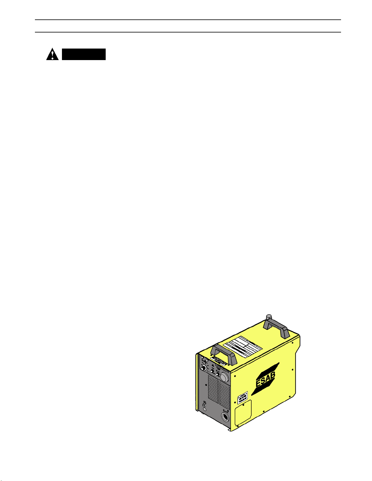
The ESP-50 is a compact, completely self-contained plasma cutting system. As
shipped, the system is ready to cut after being connected to input power, a source
of compressed air (60 - 100 psi / 4.1 - 6.9 bars) and a PT-35 torch. The ESP-50 package
uses the PT-35 torch to deliver cutting power for severing materials up to 5/8 inch
(15.9 mm) thick. Refer to the following paragraphs for descriptions of the ESP-50
packages available as well as performance specifications.
2.2 SCOPE
The purpose of this manual is to provide the operator with all the information required
to install and operate the ESP-50 plasma arc cutting package. Technical reference
material is also provided to assist in troubleshooting the cutting package.
2.3 PACKAGES AVAILABLE
2.3.1 ESP50 Mechanized Cutting Packages
The ESP-50 plasma cutting package combines the ESP-50 and PT-35 torch. A typical
package includes: ESP-50 Console/Power Source, PT-35 Torch - 25' (7.6 m) or 50' (15.2
m), Torch Spare Parts Kit and a power cable. See Section 3 for installation details.
2.4 SPECIFICATIONS: ESP50
Cuts .50 in. (12.7 mm)
1 ph. Input ...................................................................208/230 vac, 1 ph, 50/60 Hz, 46/42 A
3 ph. Input ...................................................................208/230 vac, 3 ph, 50/60 Hz, 22/20 A
....................................................................................400/460 vac, 3 ph, 50/60 Hz, 12/11 A
Output ........................................................................................... 50 amps @ 100% duty cycle
Dimensions ...................................................................................................W = 10.1” (275mm)
....................................................................................................................... H = 18.3” (465mm)
....................................................................................................................... D = 20.3” (576mm)
Weight ....................................................................................................................85 lbs. (38.6kg)
Minimum Air Requirements ...................... 250 cfh @ 60 psig (117.9 l/min @ 4.1 bars)
17
Page 18

SECTION 2 DESCRIPTION
2.5 ORDERING INFORMATION:
ESP-50, 230/230 V, 25 ft. (7.6m) PT-35 .................................................................................................................................................................................................... 0558004378
ESP-50, 208/230 V, 50 ft. (15.2m) PT-35 ...................................................................................................................................................................................................0558004379
ESP-50, 230/230 V, 25 ft. (7.6m) PT-35, without rack ....................................................................................................................................................................... 0558004973
ESP-50, 208/230 V, 50 ft. (15.2m) PT-35, without rack ......................................................................................................................................................................0558004974
ESP-50, 400CE/460 V, 25 ft. (7.6m) PT-35, with rack ......................................................................................................................................................................... 0558004376
ESP-50, 400CE/460 V, 50 ft. (15.2m) PT- 35, with rack .......................................................................................................................................................................0558004377
ESP-50, 400CE/460 V, 25 ft. (7.6m) PT-35, without rack .................................................................................................................................................................0558004374
ESP-50, 400CE/460 V, 50 ft. (15.2m) PT- 35, without rack ................................................................................................................................................................0558004375
The components that are included in the ESP-50 packages may be purchased separately by using the appropriate P/N when placing orders. Individual part
numbers are listed below:
Consoles:
ESP-50 208/230 V, 50/60 Hz, 1/3-ph ...............................................................................................................................................................................................................0558004371
ESP-50 400/460 V, 50/60 Hz, 3-ph ...................................................................................................................................................................................................................0558004372
PT-35 Torches:
PT-35 Torch, 25 ft. (7.6m), with rack ................................................................................................................................................................................................................0558004351
PT-35 Torch, 50 ft. (15.2m), with rack ..............................................................................................................................................................................................................0558004352
PT-35 Torch, 25 ft. (7.6m), without rack .........................................................................................................................................................................................................0558004353
PT-35 Torch, 50 ft. (15.2m), without rack .......................................................................................................................................................................................................0558004354
2.6 TORCH DATA
ESP-50 uses the PT-35 torch. For complete list and breakdown of parts, refer to Figure 2.1 and 2.2.
Cutting Parameters for the PT-35 Torch
CARBON STEEL
50 AMP Data, Nozzle P/N 0558004356, Heat Shield P/N 0558004357, Electrode P/N 0558005200
Metal
Thickness
in.
.625
.500
.375
.250
.125
.099
(12/13 ga.)
.059
( 16 ga.)
.042
(19 ga.)
.024
(24 ga.)
mm
15.875
12.700
9.525
6.350
3.175
2.515
1.499
1.067
0.610
Travel Speed
Optimum
ipm (mm/min)
12
25
42
82
150
225
375
450
750+
304
635
101
2082
3810
5715
9525
11430
19050+
Maximum
ipm (mm/min)
18
30
48
86
200
250
450
600
750+
457
762
1219
2184
5080
6350
11430
15240
19050+
Amps
50
50
50
50
50
50
50
50
50
Air
Pressure
psig
60
60
60
60
60
60
60
60
60
bar
4.1
4.1
4.1
4.1
4.1
4.1
4.1
4.1
4.1
Cutting
Height
in.
.125
.125
.125
.125
.125
.125
.125
.125
.125
mm
3.175
3.175
3.175
3.175
3.175
3.175
3.175
3.175
3.175
Height
in.
NR
NR
.187*
.156*
.156*
.125
.125
.125
.125
Pierce
mm
NR
NR
4.750
3.962
3.962
3.175
3.175
3.175
3.175
NR = Not Recommended
* = If using a fixed height torch or plate rider, set cutting height equal to pierce height; cutting speed may
have to be reduced due to increased cut height.
18
Page 19

SECTION 2 DESCRIPTION
Cutting Parameters for the PT-35 Torch
STAINLESS STEEL
50 AMP Data, Nozzle P/N 0558004356, Heat Shield P/N 0558004357, Electrode P/N 0558005200
Metal
Thickness
in.
.500
.375
.250
.188
.125
.105
(12/13 ga.)
.060
(16 ga.)
.043
(19 ga.)
.025
(24 ga.)
mm
12.700
9.525
6.350
4.763
3.175
2.515
1.499
1.067
0.610
Travel Speed
Optimum
ipm (mm/min)
13
22
50
70
125
172
345
750+
750+
330
558
1270
1778
3175
4368
8763
19050+
19050+
Maximum
ipm (mm/min)
18
30
60
93
162
195
390
750+
750+
457
762
1524
2362
4114
4953
9906
19050+
19050+
Amps
50
50
50
50
50
50
50
50
50
Air
Pressure
psig
bar
60
4.1
60
4.1
60
4.1
60
4.1
60
4.1
60
4.1
60
4.1
60
4.1
60
4.1
Cutting
Height
in.
.125
.125
.125
.125
.125
.125
.125
.125
.125
mm
3.175
3.175
3.175
3.175
3.175
3.175
3.175
3.175
3.175
GALVANIZED STEEL
50 AMP Data, Nozzle P/N 0558004356, Heat Shield P/N 0558004357, Electrode P/N 0558005200
Height
in.
NR
NR
.187*
.187*
.156*
.125
.125
.125
.125
Pierce
mm
NR
NR
4.750
4.750
3.962
3.175
3.175
3.175
3.175
Metal
Thickness
in.
.071
(15 ga.)
.062
(16 ga.)
.025
(25 ga.)
NR = Not Recommended
* = If using a fixed height torch or plate rider, set cutting height equal to pierce height; cutting speed may
have to be reduced due to increased cut height.
mm
1.803
1.575
0.635
Optimum
ipm (mm/min)
170
315
450
Travel Speed
4318
8001
11430
Maximum
ipm (mm/min)
210
352
750
5334
8940
19050
Amps
50
50
50
19
Air
Pressure
psig
bar
60
4.1
60
4.1
60
4.1
Cutting
Height
in.
.125
.125
.125
mm
3.175
3.175
3.175
Height
in.
.125
.125
.125
Pierce
mm
3.175
3.175
3.175
Page 20
SECTION 2 DESCRIPTION
Cutting Parameters for the PT-35 Torch
ALUMINUM
50 AMP Data, Nozzle P/N 0558004356, Heat Shield P/N 0558004357, Electrode P/N 0558005200
in.
.500
.375
.313
.250
.188
.125
.095
Metal
Thickness
12.700
mm
9.525
7.950
6.350
4.763
3.175
2.413
Travel Speed
Optimum
ipm (mm/min)
21
36
50
72
110
200
275
533
914
1270
1828
2794
5080
6985
Maximum
ipm (mm/min)
30
45
57
87
150
230
300
762
1143
1447
2209
3810
5842
7620
Amps
50
50
50
50
50
50
50
Air
Pressure
psig
60
60
60
60
60
60
60
bar
4.1
4.1
4.1
4.1
4.1
4.1
4.1
Cutting
Height
in.
.125
.125
.125
.125
.125
.125
.125
mm
3.175
3.175
3.175
3.175
3.175
3.175
3.175
Height
in.
NR
NR
.250*
.188*
.156*
.156*
.125
Pierce
mm
NR
NR
6.350
4.775
3.962
3.962
3.175
(10/11 ga.)
.049
1.245
420
10668
465
11811
50
60
4.1
.125
3.175
.125
3.175
(16 ga.)
.043
1.092
450
11430
502
12750
50
60
4.1
.125
3.175
.125
3.175
(17 ga.)
.031
0.762
750+
19050+
750+
19050+
50
60
4.1
.125
3.175
.125
3.175
(20 ga.)
NR = Not Recommended
* = If using a fixed height torch or plate rider, set cutting height equal to pierce height; cutting speed may
have to be reduced due to increased cut height.
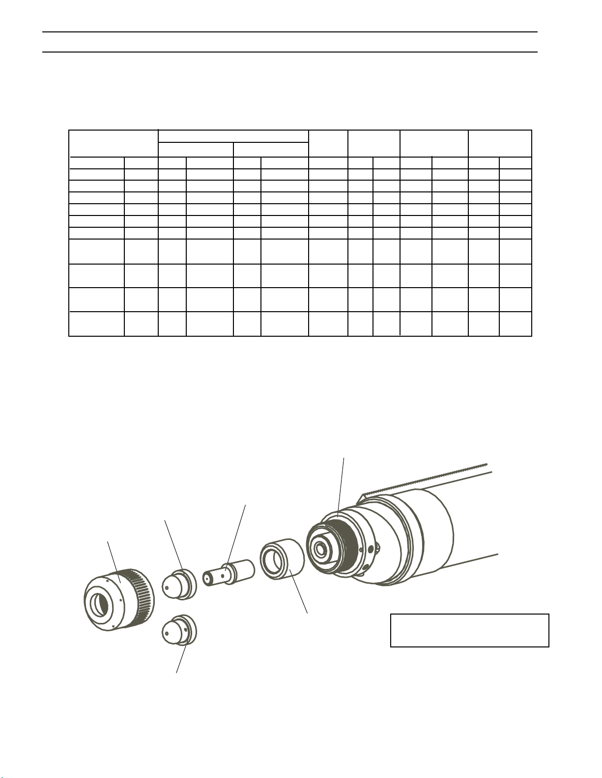
2.7 TORCH SPECIFICATIONS:
Cutting "A" Nozzle -
0558004356
Heat Shield 50A -
0558004357
Cutting "B" Nozzle -
0558004358
Electrode - 0558005200
Insulator - 0558004387
Torch Body Assembly -
0558004390
Nozzles
• 0558004356 - Standard "A" Nozzle
• 0558004358 - Special "B" Nozzle for duct
cutting & expanded metal
Figure 2-1. PT-35 Torch
20
Page 21
SECTION 2 DESCRIPTION
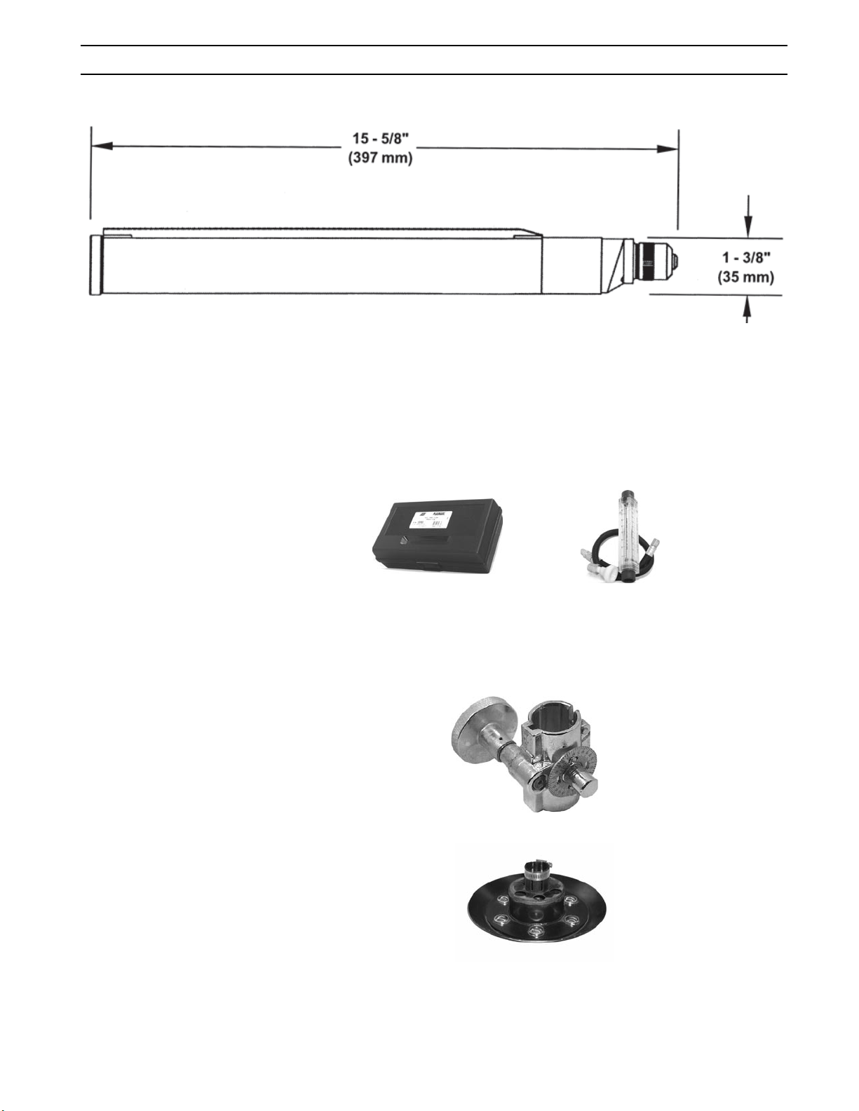
Figure 2-2. PT-35 Dimensions
2.8 OPTIONAL ACCESSORIES:
Plasma Flow Measuring Kit:
This valuable troubleshooting tool allows measurement of
the actual plasma gas flow through the torch ............................................. 19765 (0558000739)
(NOTE: Part numbers in parenthesis
apply to "CE"/European units only.)
CNC Cable 50' ..................................................................................................................0558004366
Adaptor Cable - Adaptor to directly connect HT or TD control cable to ESP-50 ..........0558004363
Torch Holder Assembly .................................................................................... 16V83 (0558004250)
Plate Rider - height control for PT-35 ........................................................................... 0560936972
Standoff Tool - Designed for use with Plate Rider for setting nozzle standoff height.
Can also be used separately. ................................................................................................................ 0558004364
21
Page 22

SECTION 2 DESCRIPTION
2.9 SPARE PARTS KITS:
50 A Spare Parts Kit ........................................................................................................0558005210
PT-35, 50 A, Spare Parts Kit, P/N 0558005210
Contents:
Description P/N Quantity
Shield, Retaining 0558004357 1
50 amp "A" Nozzle 0558004356 4
Electrode 0558005200 6
Fuse 2amp, 600vdc 0558003075 1
Insulator 0558004387 1
Consumable Value Pack .................................................................................................0558005203
Consumable Value Pack, P/N 0558005203
Contents:
Description P/N Quantity
Electrode 0558005200 10
50 amp "A" Nozzle 0558004356 15
Consumable Set ..............................................................................................................0558005201
Consumable Set, P/N 0558005201
Contents:
Description P/N Quantity
Electrode 0558005200 1
50 amp "A" Nozzle 0558004356 1
Consumable Set ..............................................................................................................0558005202
Consumable Set, P/N 0558005202
Contents:
Description P/N Quantity
Electrode 0558005200 1
50 amp "B" Nozzle 0558004358 1
22
Page 23

SECTION 3 INSTALLATION
3.1 GENERAL
CAUTION
Installing or placing any type of
filtering device will restrict the
volume of intake air, thereby sub
jecting the power source internal
components to overheating. The
warranty is void if any type of
filter device is used.
-
WARNING
ELECTRIC SHOCK CAN KILL! Precautionary measures should be taken
to provide maximum protection
against electrical shock. Be sure
that all power is off by opening the
line (wall) disconnect switch and by
unplugging the power cord to the
unit when connections are made
inside of the power source.
CAUTION
Be sure that the power source is
properly configured for your input
power supply. DO NOT connect
a power source configured for
208/230 V to a 460 V input power
supply. Damage to the machine
may occur.
Proper installation is important for satisfactory and trouble-free operation of the
ESP-50 cutting package. It is suggested that each step in this section be studied
carefully and followed closely.
3.2 EQUIPMENT REQUIRED
A source of clean, dry air that supplies 250 cfh (118.0 l/m) at 60-75 psig (4.1 - 5.2 bars)
is required for the cutting operation. The air supply should not exceed 150 psig (10.3
bars) (the maximum inlet pressure rating of the air filter-regulator supplied with the
package).
3.3 LOCATION
Adequate ventilation is necessary to provide proper cooling of the ESP-50. The
amount of dirt, dust, and excessive heat to which the equipment is exposed, should
be minimized. There should be at least one foot of clearance between the ESP-50
power source and wall or any other obstruction to allow freedom of air movement
through the power source.
3.4 INSPECTION
A. Remove the shipping container and all packing material and inspect for evidence
of concealed damage which may not have been apparent upon receipt of the
ESP-50. Notify the carrier of any defects or damage at once.
B. Check container for any loose parts prior to disposing of shipping materials.
C. Check air louvers and any other openings to ensure that any obstruction is
removed.
3.5 PRIMARY ELECTRICAL INPUT CONNECTIONS
FIGURE 32
NOTE: If using 200(208) V input power, the ESP-50 must be reconnected for 200 V
use as directed in Section 3.7 and Figure 3-4.
WARNING
The chassis must be connected to
an approved electrical ground.
Failure to do so may result in
electrical shock, severe burns
or death.
If using 400 V input power, the ESP-50 must be reconnected as directed in
Section 3.8, Figure 3-5.
NOTE: The 208/230 V models are equipped with a plug for single-phase connection
only. The plug is mounted to a 4-conductor cable. If 3-phase connection is
desired, remove the plug and proceed as described.
A line (wall) disconnect switch with fuses or circuit breakers should be provided at
the main power panel (see Table 3-1 for fuse sizes). The input power cable of the
console may be connected directly to the disconnect switch or you may purchase a
proper plug and receptacle from a local electrical supplier. If using plug/receptacle
combination, see Table 3-1 for recommended input conductors for connecting receptacle to line disconnect switch.
23
Page 24
F14-080 A
May, 1999
Installation, Operation, and Maintenance Manual for the
SHADOW
GANTRY SHAPE CUTTING MACHINE
SECTION 3 INSTALLATION
3.6 SECONDARY ELECTRICAL OUTPUT CONNECTIONS
FIGURE 32
1. For operator safety, the torch connections are located on the output terminal
board behind the lower portion of the front panel. Remove access door to
output terminal board from right panel of power source.
2. Thread the power cable & pilot arc cable of the PT-35 through the right open
bushing of the front panel. Connect power cable to the torch fitting (left-hand
threads); bolt the pilot arc cable ring connection to the copper terminal. Make
sure the power and pilot arc cable connections are wrench-tight.
3. Reassemble the access door to the power source.
4. Connect your air supply to the inlet connection of the filter-regulator.
WARNING
Before making any connections
to the power source output terminals, make sure that all primary
input power to the power source is
deenergized (off) at the main disconnect switch and that the input
power cable is unplugged.
5. Clamp the work cable to the workpiece. Be sure the workpiece is connected
to an approved earth ground with a properly sized ground cable.
Input Requirements Input & Gnd Fuse
Volts Phase Amps Conductor Size
CU/AWG Amps
208 1 55A 6 80
208 3 26A/Ph. 6 50
230 1 49A 6 80
230 3 24A/Ph. 6 50
400 3 13 10 25
460 3 11 10 25
Torch cable
Table 3-1. Recommended Sizes For Input Conductors and Line Fuses
CNC Control cable
Clamp the work cable to the
workpiece. Be sure the workpiece
is connected to an approved earth
ground with a properly sized
ground cable.
SAFETY GROUND
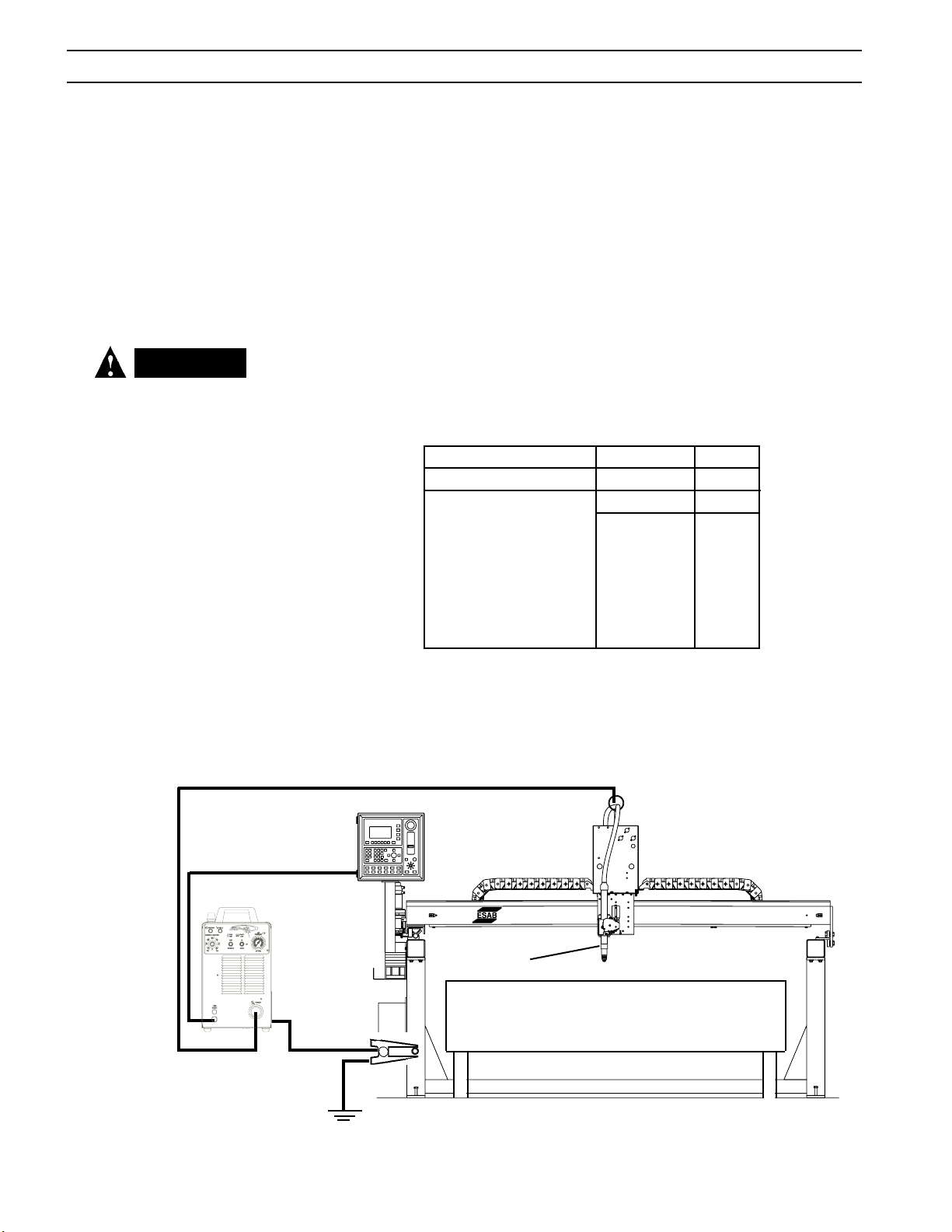
Figure 3-1. PowerCut Interconnection Diagram
24
PT-35
Page 25
SECTION 3 INSTALLATION
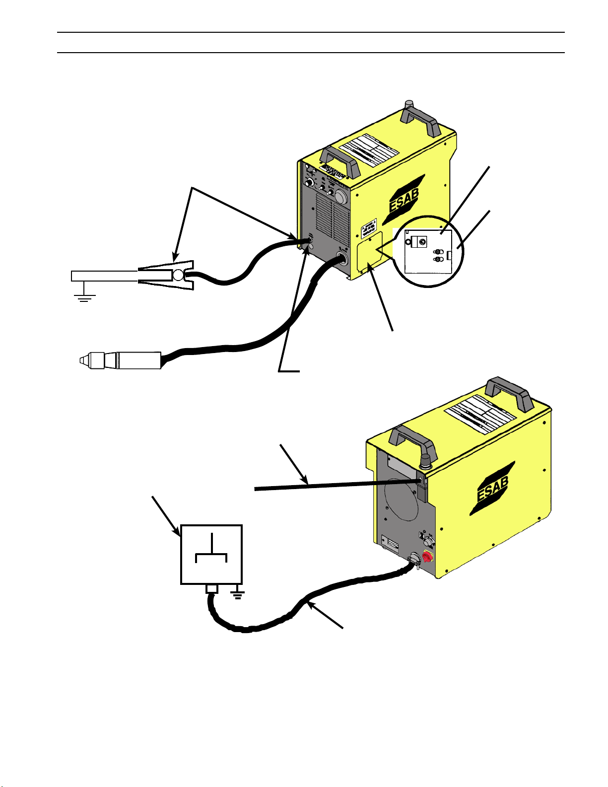
TORCH
PILOT
Allow at least 10 ft. (3m)
between work and power source
WORK
SAFETY GROUND
ARC
CONNECTION
TORCH
POWER
CABLE
CONNECTION
Prefiltered AIR SUPPLY (Customer Supplied)
(100 psig max / 6.9 bars max)
CUSTOMER FUSED LINE DISCONNECT SWITCH
(See Table 3.1 and WARNING in regards to chassis
ground in Section 3.5.)
ACCESS DOOR FOR
TORCH CONNECTION
ACCESS FOR CNC
INTERFACE CONNECTIONS.
(See Detail “A”)
INPUT POWER CABLE
(See Table 3.1)
NOTE: The 208/230 V models are equipped with a plug for single-
phase connection only. The plug is mounted to a 4-conductor
cable. If 3-phase connection is desired, remove and discard
the plug and refer to Sect. 3.5.
Figure 3-2. ESP-50 Interconnection Diagram
25
Page 26
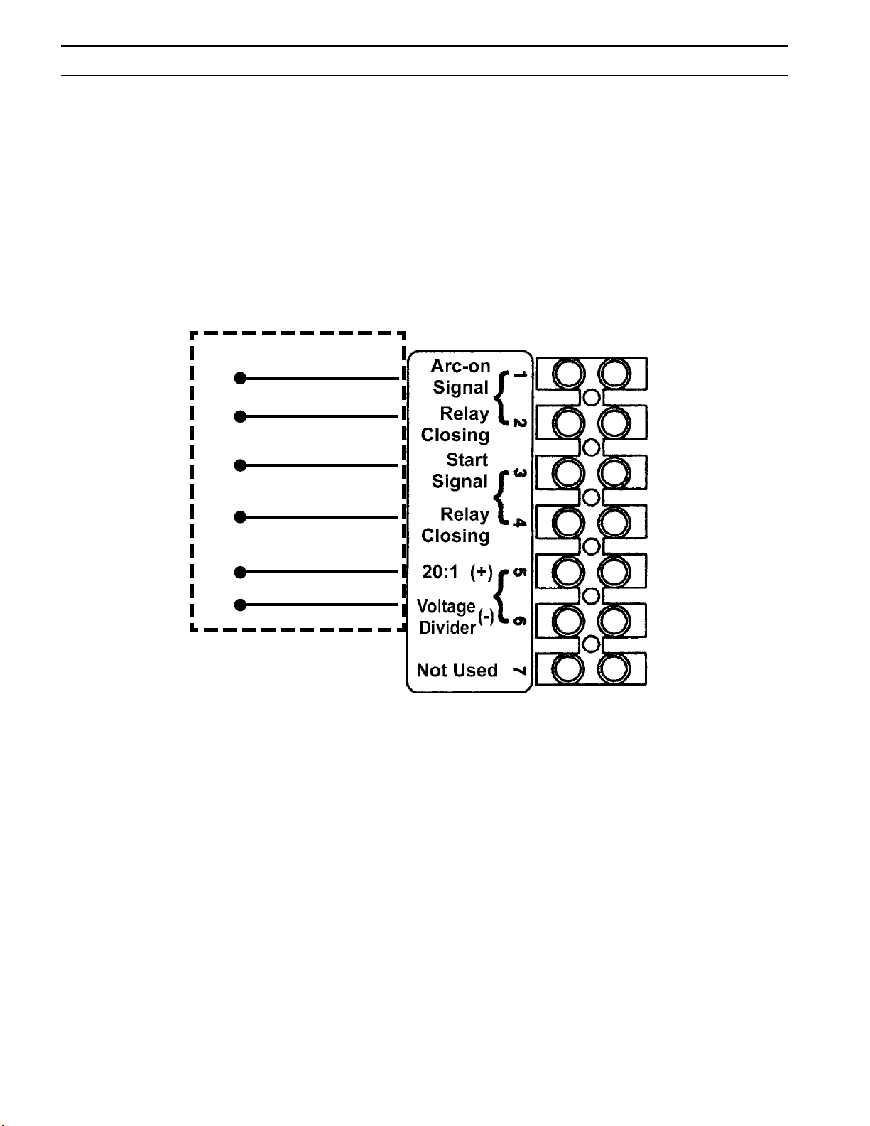
SECTION 3 INSTALLATION
FACTORY WIRED
MACHINES
BLUE
1
ORANGE
2
RED
3
4
BLACK
GREEN
5
WHITE
6
DETAIL "A"
Figure 3.3 - MECHANICAL CUTTING INTERFACE DIAGRAM
CNC Interface Connection (Located inside console, left side of base.)
26
Page 27
SECTION 3 INSTALLATION
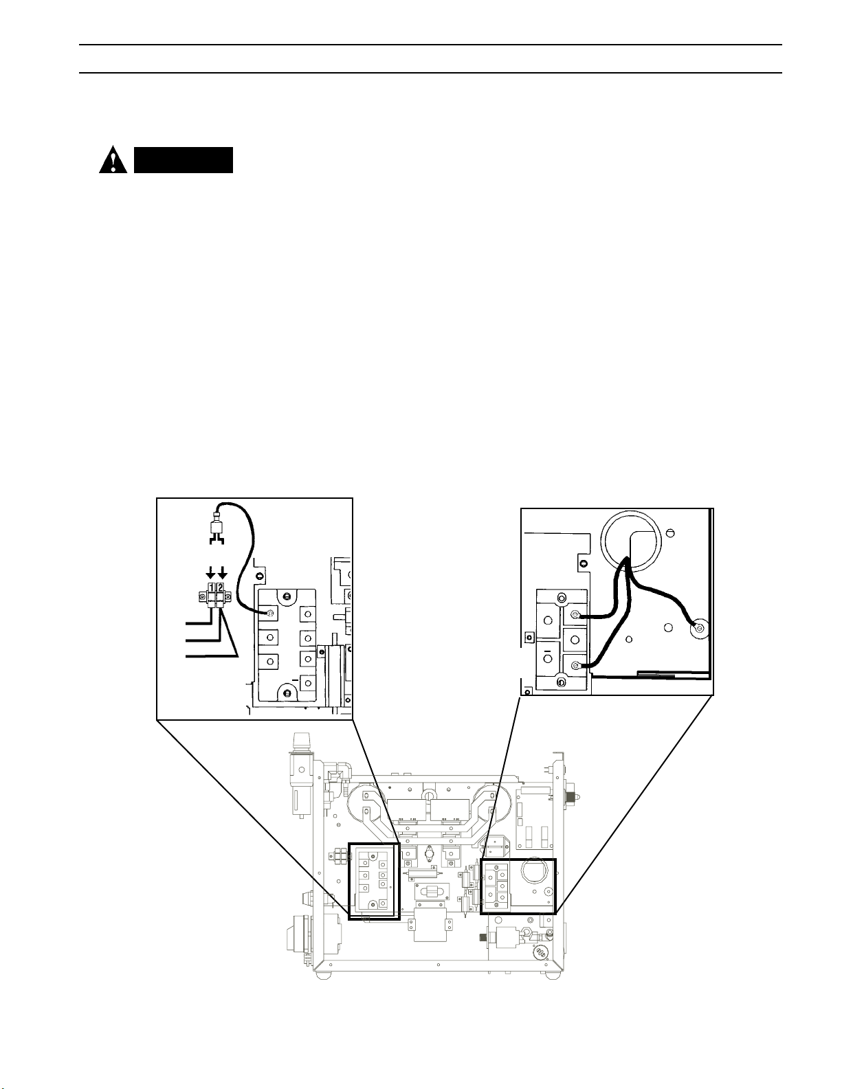
3.7 CONNECTING ESP50 FOR 200208 VAC INPUT
WARNING
ELECTRIC SHOCK CAN KILL! Precautionary measures should be
taken to provide maximum protection against electrical shock.
Be sure that all power is off by
opening the line (wall) disconnect switch and by unplugging
the power cord to the unit when
primary electrical connections
are made to the power supply.
Figure 3.4.A
GRY
208
230
VAC
VAC
TB5
BLK
BLK
GRY
The ESP-50 power source with 200/230 vac, single-phase input capability is factory
set for 230 vac input. If using 200(208) vac input, the ESP-50 must be reconnected
as follows before connecting to your input power:
1. Remove the cover from the ESP-50 power source.
2. Locate the Input Bridge (IBR) and TB5 terminal block (see Figure 3.4.A) on the
left side towards the rear panel. Disconnect the gray lead from TB5-2 and then
connect it to TB5-1.
3. Locate the output bridge (D1) on left side towards the front panel (see Figure
3.4.B). Disconnect and swap leads X2 and X3 from the main transformer. For
200(208) vac input, X2 is connected to TB3 and X3 is connected to terminal 3
of D1. Make sure the connections are firmly tightened.
4. Leave all other wires the same.
5. Reinstall the cover and connect the ESP-50 to 208 vac input power.
Note: Factory set for 230 VAC input.
For 208VAC move GRY wire from TB5-2 to TB5-1, move T1-X2 to TB3 and T1-X3 to D1-3
FROM MAIN TRANSFORMER
230 VAC
INPUT
T1-X3
INPUT
TB3
(IBR)
INPUT
BRIDGE
R
S G
+
T
R2
OUTPUT BRIDGE
(D1)
Figure 3.4.B
~
1
+
~
2
~
3
X1
208 VAC
T1-X2
Figure 3-4. Original Factory Setup for 230 Vac Input on
Power Source with 200/230 Vac Input Power Capability
27
Page 28
SECTION 3 INSTALLATION
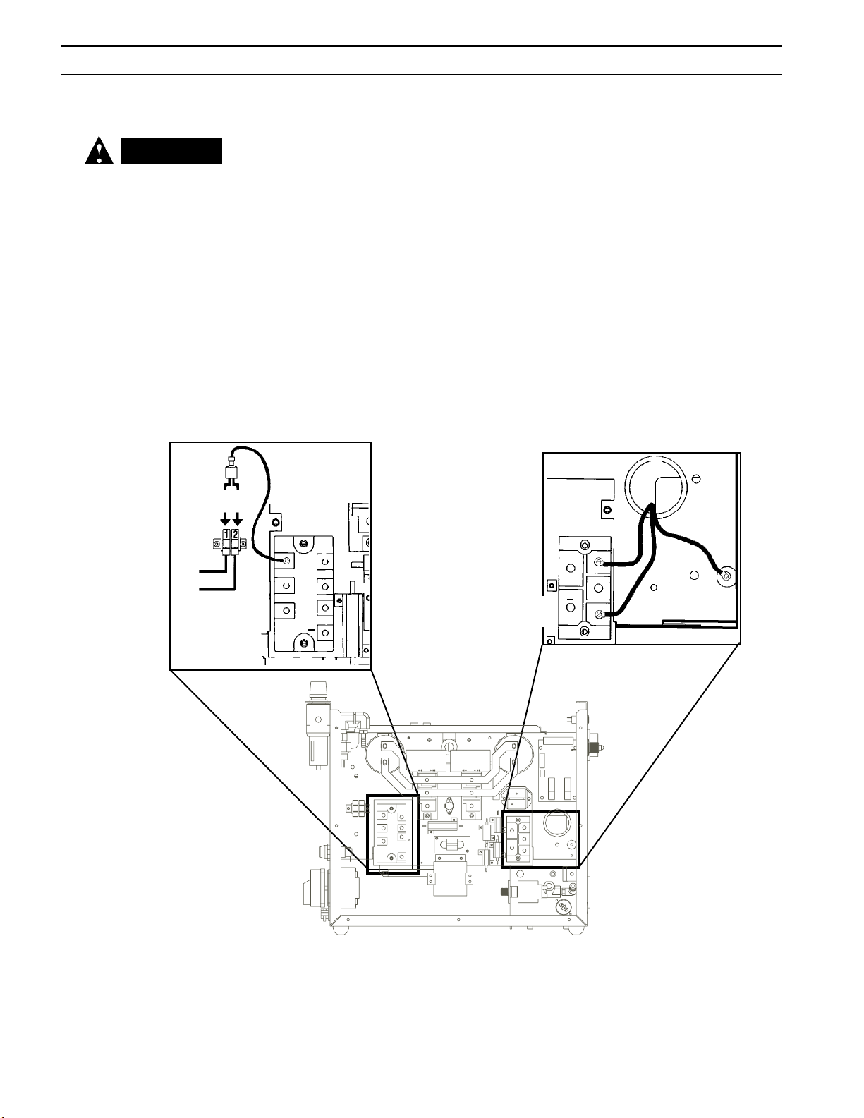
3.8 CONNECTING ESP50 FOR 400/460 VAC INPUT
WARNING
ELECTRIC SHOCK CAN KILL! Precautionary measures should be
taken to provide maximum protection against electrical shock.
Be sure that all power is off by
opening the line (wall) disconnect switch and by unplugging
the power cord to the unit when
primary electrical connections
are made to the power supply.
Figure 3.5.A
400
460
VAC
VAC
TB5
BLU
WHT
The ESP-50 power source with 400/460 vac, 3-phase input capability is factory set
for 460 vac input. If using 400 vac input, the ESP-50 must be reconnected as follows
before connecting to your input power:
1. Remove cover from the ESP-50 power source.
2. Locate the Input Bridge (IBR) and TB5 terminal block (see Figure 3.5.A) on the
left side towards the rear panel. Disconnect the gray lead from TB5-2 and then
connect it to TB5-1.
3. Locate the output bridge (D1) on left side towards the front panel (see Figure
3.5.B). Disconnect and swap leads X2 and X3 from the main transformer. For
400 vac input, X2 is connected to TB3 and X3 is connected to terminal 3 of D1.
Make sure the connections are firmly tightened.
4. Leave all other wires the same.
5. Reinstall cover and connect the ESP-50 to 400 vac input power.
FROM MAIN TRANSFORMER
460 VAC
INPUT
T1-X3
INPUT
GRY
(IBR)
INPUT
BRIDGE
R
S G
+
T
R2
OUTPUT BRIDGE
(D1)
Figure 3.5.B
~
1
+
~
2
~
3
X1
400 VAC
T1-X2
TB3
Figure 3-5. Original Factory Setup for 460 Vac Input on
Power Source with 400/460 Vac Input Power Capability
28
Page 29
SECTION 4 OPERATION
4.1 ESP-50 CONTROLS (FIGURE 4-1)
WARNING
ELECTRIC SHOCK can kill.
• Do NOT operate the unit with the
cover removed.
• Do NOT apply power to the unit
while holding or carrying the
unit.
• Do NOT touch any torch parts
forward of the torch h a n d l e
(nozzle, heat shield, electrode,
etc.) with power switch on.
WARNING
ARC RAYS can burn eyes and skin;
NOISE can damage hearing.
• Wear welding helmet with No. 6
or 7 lens shade.
• Wear eye, ear, and body protection.
A. Power Switch (located on rear panel). When placed in ON position, the white
pilot light will glow indicating control circuit is energized and the cooling fan
will run.
B. Output Current Control. Adjustable from 20 to 50 amperes.
C. Air Test Switch. When placed in Test position, air filter-regulator can be adjusted
to desired pressure (60 - 75 psig / 4.1 - 5.2 bars) before cutting operations. Allow air to flow for a few minutes. This should remove any condensation that
may have accumulated during shutdown period. Be sure to place switch in
OPERATE position before starting cutting operations.
D. Pilot Arc Select Switch.
Hi: Set pilot arc current level to "High" when improved stability is needed. May
lessen consumable life.
Low: Maintains "Low" pilot arc current level. May improve consumable life.
Auto: Adjusts pilot arc based on output current selected. Use for standard
cutting.
E. Fault Light. Will glow amber under the following conditions and opera-
tions will come to a complete stop.
CAUTION
Position the ESP-50 at least 10
feet (3 meters) from the cutting
area. Sparks and hot slag from
the cutting operation can damage
the unit.
Start Signal: On power-up, fault light will be on continuously when a start
signal is present. Remove start signal to reset.
Parts in Place Fault: The fault light will be on continuously at power-up. This
indicates missing or worn consumables. Turn power off and inspect torch.
Over Temperature: The fault light will be mostly off but will flick on for
about 1/10th of a second every second. This indicates that the duty cycle has
been exceeded. Allow the power source to cool down before continuing to
operate.
High/Low Line Voltage: The fault light will rapidly blink on and off (five
times per second). This indicates that the input voltage is outside the “+ or -”
15% range of the input rating.
Over-Current: The fault light will be on continuously. This indicates that input
current has been exceeded.
All fault signals will remain on for a minimum of 10 seconds. If fault clears,
all will reset automatically except for over-current. To clear over-current,
the power must be shut off for 5 seconds and then turned back on.
29
Page 30
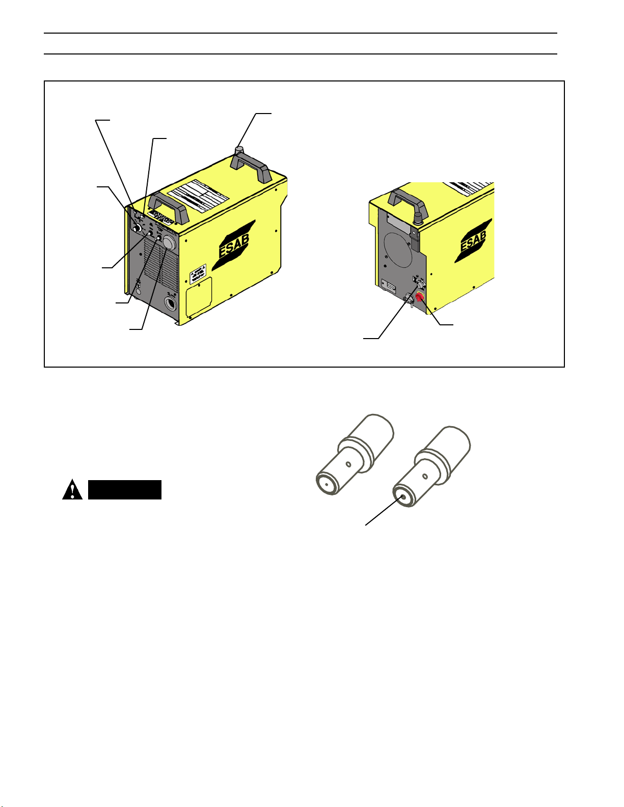
SECTION 4 OPERATION
CURRENT
CONTROL
KNOB
AIR TEST
SWITCH
PILOT ARC
SELECT SWITCH
PRESSURE
POWER LIGHT
(WHITE)
AIR
GAUGE
FAULT LIGHT
(AMBER)
AIR REGULATOR
CONTROL KNOB
FUSE (3A)
Figure 4-1. ESP-50 Controls
REAR VIEW
POWER ON-OFF
(I-O) SWITCH
CAUTION
REPLACE ELECTRODE BEFORE
LENGTH BECOMES SHORTER
THAN .060" INCH (1.5 MM)
NEW
Replace when eroded beyond
.060"(1.5mm) Depth.
WORN
Figure 4-2. Electrode Wear Limit
NOTE: When replacing the nozzle, always inspect the electrode for wear. If electrode
wear is greater than .060" (1.5 mm), replace the electrode. If the electrode
is used beyond this recommended wear limit, damage to the torch and
power source may occur. Nozzle life is also greatly reduced when using
the electrode beyond the recommended limit. Refer to Figure 4-2.
30
Page 31

SECTION 4 OPERATION
4.2 COMMON CUTTING PROBLEMS
Listed below are common cutting problems followed by the probable cause of each.
If problems are determined to be caused by the ESP-50, refer to the maintenance
section of this manual. If the problem is not corrected after referring to the maintenance section, contact your ESAB distributor.
A. Insufficient Penetration.
1. Current too low.
2. Cutting speed too fast.
3. Damaged cutting nozzle.
4. Improper air pressure.
5. Low air flow rate.
B. Main Arc Extinguishes.
1. Cutting speed too slow.
2. Worn electrode.
C. Dross Formation. (In some materials and thicknesses, it may be impossible
to get dross-free cuts.)
1. Current too low.
2. Cutting speed too fast or too slow.
3. Improper air pressure.
4. Faulty nozzle or electrode.
5. Low air flow rate.
D. Double Arcing. (Damaged Nozzle Orifice.)
1. Low air pressure.
2. Damaged cutting nozzle.
3. Loose cutting nozzle.
4. Heavy spatter accumulation on nozzle.
E. Uneven Arc.
1. Damaged cutting nozzle or worn electrode.
F. Unstable Cutting Conditions.
1. Incorrect cutting speed.
2. Loose cable or hose connections.
3. Electrode and/or cutting nozzle in poor condition.
G. Main Arc Does Not Strike.
1. Worn electrode.
2. Loose connections.
3. Work cable not attached.
H. Poor Consumable Life.
1. Improper gas pressure.
2. Contaminated air supply.
3. Low air flow rate.
31
Page 32

SECTION 4 OPERATION
32
Page 33
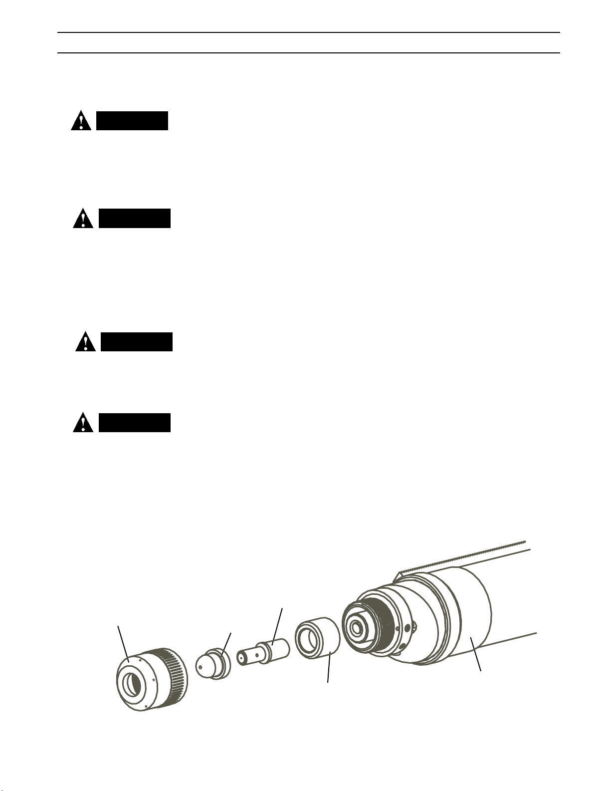
SECTION 5 MAINTENANCE
5.1 GENERAL
If this equipment does not operate properly, stop work immediately and investigate
WARNING
Be sure that the wall disconnect
switch or wall circuit breaker
is open before attempting any
inspection or work inside of the
ESP-50.
CAUTION
the cause of the malfunction. Maintenance work must be performed by an experienced person, and electrical work by a trained electrician. Do not permit untrained
persons to inspect, clean, or repair this equipment. Use only recommended replacement parts.
5.2 INSPECTION AND CLEANING
Frequent inspection and cleaning of the ESP-50 is recommended for safety and proper
operation. Some suggestions for inspecting and cleaning are as follows:
Water or oil occasionally accumulates in compressed air lines.
Be sure to direct the first blast of
air away from the equipment to
avoid damage to the ESP-50.
WARNING
Make sure power switch on
ESP-50 is in OFF position before
working on the torch.
WARNING
Always replace torch with the
proper torch manufactured by
ESAB since it alone contains ESAB's patented safety interlock.
A. Check work cable for secured connection to workpiece.
B. Check safety earth ground at workpiece and at power source chassis.
C. Check heat shield on torch. It should be replaced if damaged.
D. Check the torch electrode and cutting nozzle for wear on a daily basis. Remove
spatter or replace if necessary.
E. Make sure cable and hoses are not damaged or kinked.
F. Make sure all plugs, fittings, and ground connections are tight.
G. With all input power disconnected, and wearing proper eye and face protection,
blow out the inside of the ESP-50 using low-pressure dry compressed air.
H. Occasionally, bleed all water from the filter beneath the air filter-regulator.
5.3 PT35 TORCH CONSUMABLE PARTS
To assemble the consumable parts, refer to Figure 4-1.
A. Thread electrode into torch body, hand tighten.
B. Insert insulator into torch as shown.
C. Place nozzle into the shield.
D. Thread assembly to the torch body and hand tighten. Always make sure the
shield is tight before cutting.
SHIELD
ELECTRODE
NOZZLE
TORCH BODY
INSULATOR
IMPORTANT!
MAKE SURE SHIELD IS TIGHT!
Figure 5-1. Assembly of PT-35 Torch Front End Parts
33
Page 34
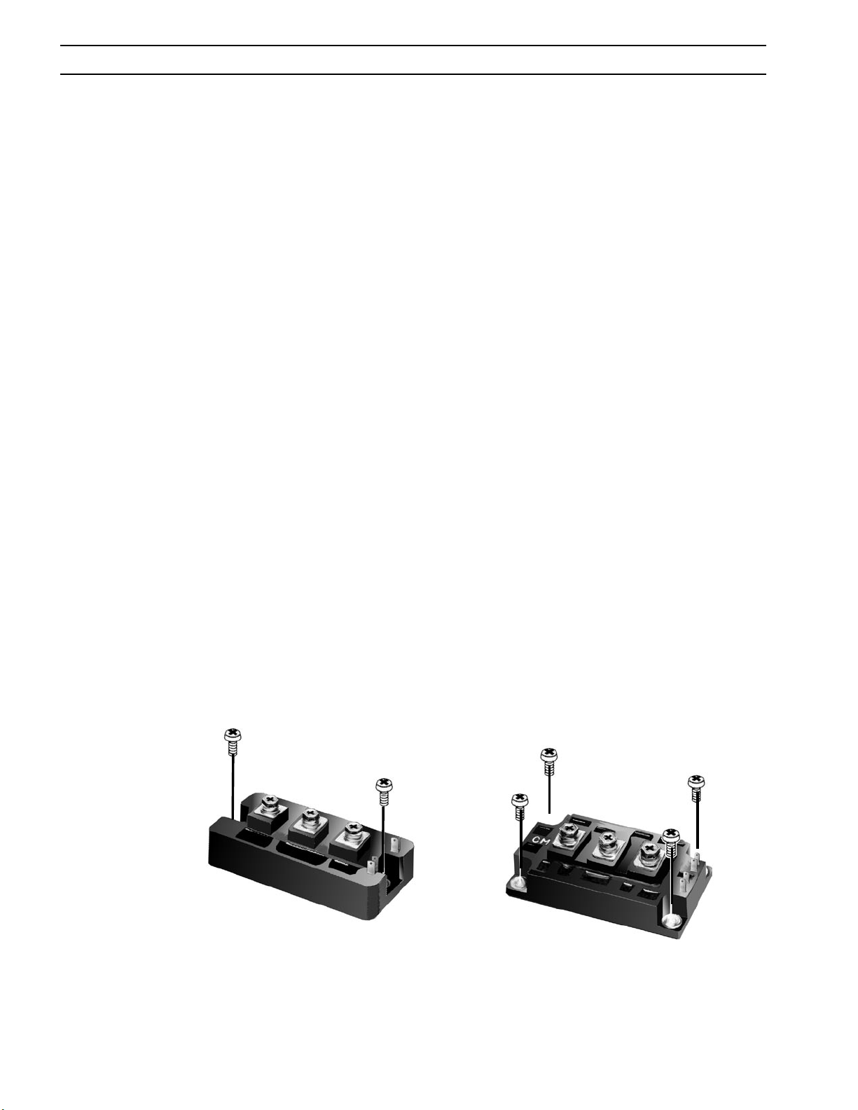
SECTION 5 MAINTENANCE
5.4 IGBT Handling & Replacement
Since IGBT gates are insulated from any other conducting region, care should be taken to prevent static build
up, which could possibly damage gate oxides. All IGBT modules are shipped from the factory with conductive
foam contacting the gate and emmiter sense pins.
Always ground parts touching gate pins during installation. In general, standard ESD precautlions application
to FETs should be followed.
Other handling precautions that should also be observed are as follows:
• Use grounded work station with grounded floors and grounded wrist straps when handling devices.
• Use a 100Ω resistor in series with the gate when performing curve tracer tests.
• Never install devices into systems with power connected to the system.
• Use soldering irons with grounded tips when soldering to gate terminals.
When mounting IGBT modules on a heatsink, certain precautions should be taken to prevent any damage against
a sudden torque. If a sudden torque (“one-sided tightening”) is applied at only one mounting terminal the ceramic
insulation plate or silicon chip inside the module may get damaged.
The mounting screws are to be fastened in the order shown in Figure 4-3. Also, care must be taken to achieve maximum contact (i.e. minimum contact thermal resistance) for the best heat dissipation.
Application of a thermal pad on the contact surface improves it thermal conductivity. See Replacement Parts section
for the required pad.
A torque wrench should be used. Tighten mounting screws to 28 in-lbs
(3.2 m-n); wire connecting screws to 19 in-lbs (2.1 m-n). If torque is too heavy, the device can damage like the above
“one-sided tightening”.
Two-Point Mounting Type
Temporary tightening Final tightening-
Four-Point Mounting Type
Temporary tightening Final tightening-
Figure 5-2. Screw Fastening Order
34
Page 35

SECTION 6 TROUBLESHOOTING
6.1 TROUBLESHOOTING
WARNING
ELECTRIC SHOCK CAN KILL! Be
sure that all primary power to
the machine has been externally disconnected. Open the
line (wall) disconnect switch or
circuit breaker before attempting inspection or work inside of
the power source.
WARNING
Voltages in plasma cutting
equipment are high enough to
cause serious injury or possibly
death. Be particularly careful
around equipment when the
covers are removed.
Check the problem against the symptoms in the following troubleshooting guide. The
remedy may be quite simple. If the cause cannot be quickly located, shut off the input
power, open up the unit, and perform a simple visual inspection of all the components
and wiring. Check for secure terminal connections, loose or burned wiring or components, bulged or leaking capacitors, or any other sign of damage or discoloration.
The cause of control malfunctions can be found by referring to the sequence of operations
and electrical schematic diagram (Figure 5-1) and checking the various components.
A volt-ohmmeter will be necessary for some of these checks.
NOTE: Before checking voltages in the circuit, disconnect the power from the high
frequency generator to avoid damaging your voltmeter.
6.2 TROUBLESHOOTING GUIDE
A. Power Light (PL1) does not come on.
1. Visually inspect the machine for any damage.
2. Check if the cooling fan is running. If not, then check the following :
a. Check if the machine power cord is plugged to the input power recep-
tacle.
b. Measure the input power at the receptacle. If not present, then check the
wall disconnect switch and it’s fuses.
c. Check Fuse (F1). If fuse is ok, then check the input switch (S1) for proper
operation. Replace if defective.
3. If above items check OK , the problem is internal. Send unit to an Authorized
Repair Station for repair.
a. If the cooling fan is running, then measure voltage between pins
P2-11 and P2-14 of the control board (should be 115 VAC). If ther
is no voltage, then replace transformer T2.
b. If the voltage is present, then the pilot light may be burnt out.
B. Fault light remains on at power-up.
1. Verify start signal is not present. If so, clear start signal, fault should
reset.
2. Switch power to OFF, verify consumables are installed correctly.
C. No Air Flow
1. Check air inlet supply. Unit requires 250 CFH (118 l/m) at 60 psig 4.1
bars).
2. Check air hose and connections. Tighten if leaking.
35
Page 36

SECTION 6 TROUBLESHOOTING
3. Does air flow when “air test” switch is in test position?
a. If not, check torch consumables, replace if necessary.
b. If above items check OK , the problem is internal. Take unit to an Authorized Repair
Station for repair.
D. The Power light is on, but nothing happens when the torch switch is depressed. Fault light
does not activate.
1. Check the following:
a. With the machine power on, depress the torch switch. On the control board the LED 1 should
be lit as long as the switch is depressed. If not then check:
i. Turn power off to the machine. Unplug control board. Put an ohmmeter across P5-1 and
P5-2 to take resistance reading. Depress torch switch. Meter should read a short. If not, then
one of the following is not working properly:
ii. Torch switch or the leads. Unplug the torch switch leads at the machine. Put a meter across
the two plug pins. Should read a short when the torch switch is depressed. If not, then either
broken switch leads or malfunctioning switch.
b. Check T2 transformer secondary voltages at the plugs P1 and P2. Refer to system schematic.
Replace the transformer if the correct secondary voltages are not present.
c. If everything above checks out all right, then the PCB1 Control Board should be replaced.
E. Fault light activates when torch switch is closed.
The Fault circuit is used to monitor conditions necessary for the safe operation of the ESP-50.
The fault light will glow amber under the following conditions and operations will come to a
complete stop:
1. High/Low line voltage. The Fault Light will rapidly blink on and off (5 times per second). This indicates
that the input voltage is outside the “+” or “-” 15% safe operating range rating.
2. Over Temperature. The fault light will be mostly off but will blink on for 1/10th of a second, every
second. This generally indicates that the duty cycle has been exceeded. Allow the power source to
cool before returning to operate.
a. Thermal switch may be open. It will open if the temperature at the IGBT base reaches 94°C. With
the machine power off, check the continuity between P1-1 and P1-2 of the control board. If the
switch is OK, then the ohmmeter should read a direct short. If not then it should read open.
b. If the switch is malfunctioning, replace it. Clean the surface of the heat sink before installing the
switch.
36
Page 37

SECTION 6 TROUBLESHOOTING
3. Over Current. The fault light will be on continuously. This indicates that the input current to
the main transformer has exceeded preset limits.
a. To check if the output is shorted, remove the heat shield and nozzle from the torch and
measure the resistance by putting the ohmmeter lead ”+” of the meter to “+” output terminal
and Work, “-” lead of the meter to the “-” output torch terminal. Reading should be about 2 K
Ohms. Reverse the voltmeter leads, the resistance reading should be less than 1.5 K Ohms.
b. If the resistance reading is different than above, check the torch and output bridge.
F. Air is On but nothing happens when torch switch is operated.
1. Check the torch. Make sure that the heat shield is very tight.
2. Any one of the following may not be working properly:
a. Check the operation of the Thermal Switch. See D.3.a. above.
b. Check Air Check switch operation. It might be stuck in On position. Pilot arc will not initiate
if this switch is in the ON position.
c. Measure voltage across C1 or C2 capacitor. It should be as follows:
approx. 325 VDC for the 208/230 volt unit.
approx. 280 VDC to 325 VDC for the 400 or 460 volt unit
If not, one of following could be malfunctioning:
1). Check the capacitors C1 and C2 for any damage.
2.) Check input bridge/SCR Module (IBR) This can be checked without taking it out of
the circuit using an volt/ohmeter. Replace it if found malfunctioning. Follow bridge
installation instructions.
3.) Check Inrush current resistor, R10, located on the input bridge heat sink. Replace it
if malfunctioning.
d. IGBTs (2 on 230 V, and 1 on the 400 V & 460 V units) may be blown. See IGBT installation pro-
cedure. Before replacing IGBTs, make sure to check the zener diodes and pico fuses on the
IGBT driver boards.
G. Pilot Arc is on but Main Arc does not transfer.
1. Make sure work clamp is connected to work material.
2. Check the torch. Replace consumables if necessary.
37
Page 38

SECTION 6 TROUBLESHOOTING
H. Poor Cutting Performance.
1. Check air supply regulator . It should be adjusted to 65 - 75 psig (4.5 - 5.2 bars).
2. The air supplied to the torch should be free of oil and water.
3. Make sure the consumables in the torch are acceptable.
4. Check the output. Use a calibrated current probe capable of measuring 100 amps.
I. Air does not shut off.
1. Check air test, the gas solenoid valve is energized when the switch is in the “on” position.
a. Check voltage to solenoid coil, if present when torch switch is unplugged, replace PCB1.
b. Turn off primary power to the power source. If gas continues to flow, replace the gas solenoid.
c. Turn on primary power and check the status of the Fault light. If the Fault light is on continuously
and gas is on continuously, turn off primary power and inspect the torch for proper assembly of
the electrode and nozzle. Press firmly on the electrode and verify that it retracts when pressed,
and returns forward when released.
d. Reassemble the electrode and nozzle and turn on primary power. After approximately two
seconds the gas should come on briefly then go off. If the Fault light comes on continuously and
gas remains off, check for defective torch trigger or shorted torch trigger leads.
J. Main arc is difficult to start.
1. The most common reason is worn or missing consumables. Check and replace if necessary.
2. Input air must be clean and dry.
3. Input air pressure must be between 65 - 75 psig (4.5 - 5.2 bars).
4. Torch connections must be tight.
5. Work cable and clamp must be in good condition and must make a good electrical connection to the
material to be cut.
6. If above items check OK , the problem may be internal.
a. Missing or weak pilot arc. Check pilot arc resistors and pilot arc wiring.
Send unit to an Authorized Repair Station for repair.
38
Page 39

SECTION 6 TROUBLESHOOTING
50 µsec
0
-13 vdc
13 vdc
40 usec - LPG50
50 usec - LPG80
6 usec - LPG50
9 usec - LPG80
6.3 REFERENCE VOLTAGE CHECKS
A. Control Board Assembly (PCB1)
1. LED’s
LED-1 - Torch Switch
LED-3 - Gas Solenoid Valve
2. Voltage Test Points
Tests are made with power on - no arc.
TP-0 - Ground
TP-1 - +15 vdc
TP-2 - +12 vdc
TP-3 - -12 vdc
TP-4 - +5 vdc
TP-9 - IGBT’s driving signal - switching frequency = 20 KHz
TP-10 - IGBT’s driving signal - switching frequency = 20 KHz
For 208/230 VAC input, the IGBT off time is 3µsec.
For 400/460 VAC input, the IGBT off time is 3µsec.
Figure 6.1 IGBT Gating Signal
39
Page 40
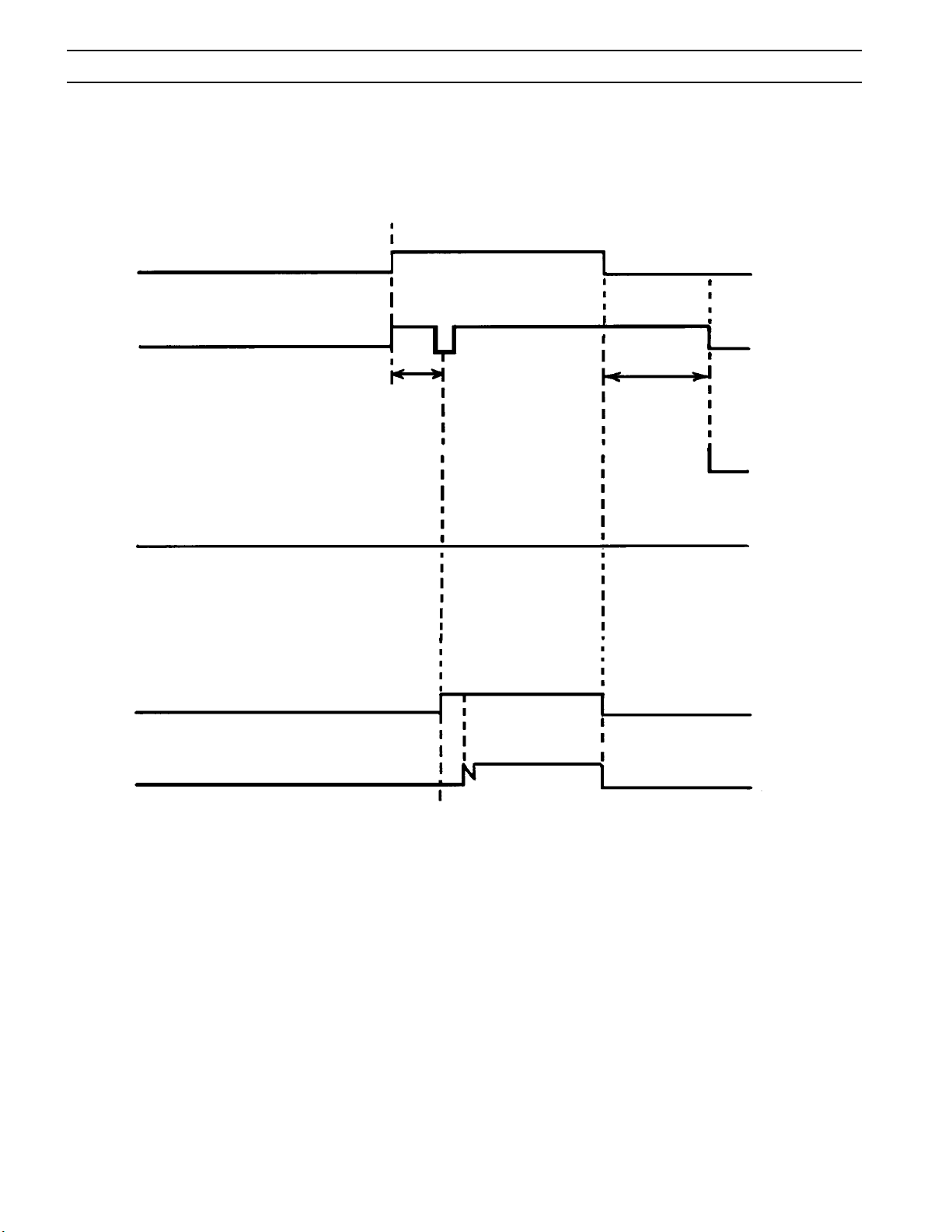
SECTION 6 TROUBLESHOOTING
6.4 SEQUENCE OF OPERATION
START SIGNAL
GAS SOLENOID VALVE
FAULT OVERLOAD LIGHT
.5 SEC.
PREFLOW
OPEN
OFFON
CLOSE
10 SEC
POSTFLOW
INVERTER
CUTTING ARC (CURRENT)
NOTES:
1. When the start signal is turned "on" during postflow period, the postflow and preflow times are canceled.
2. When the amber fault light comes on, cutting operation should be stopped. The postflow time starts from the moment
the start signal is removed.
NOTE:
Schematics and Wiring Diagrams on 11” x 17”
paper are included
inside the back cover of this manual.
40
Page 41

SECTION 7 REPLACEMENT PARTS
7.0 Replacement Parts
7.1 General
Always provide the serial number of the unit on which the parts will be used. The serial number is stamped on
the unit nameplate.
7.2 Ordering
To ensure proper operation, it is recommended that only genuine ESAB parts and products be used with this
equipment. The use of non-ESAB parts may void your warranty.
Replacement parts may be ordered from your ESAB Distributor.
Be sure to indicate any special shipping instructions when ordering replacement parts.
Refer to the Communications Guide located on the back page of this manual for a list of customer service phone
numbers.
Note
Bill of material items that have blank part numbers are provided for customer information only.
Hardware items should be available through local sources.
41
Page 42
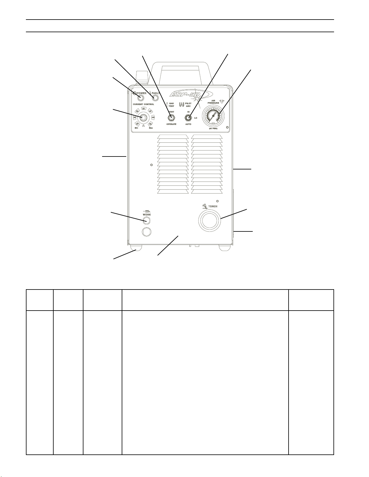
SECTION 7 REPLACEMENT PARTS
16
10, 11
1, 2
6
5, 4
7
3, 4
8, 9
15
17
14
12
13
Figure 7-1. ESP-50 Power Source, Front View
Item Qty. Part Circuit
No. Req. No. Description Symbol
1 1 137630611 KNOB
2 1 0558001176 POT. 10K 3W (NOMEX INSUL. - 676876) R1
3 1 897W65 SWITCH TOGGLE SPST 3 POS 15 A 125 V S3
4 2 951474 SWITCH SEAL BLACK
5 1 634518 SWITCH TOGGLE DPDT 2 POS 15 A 125 V S2
6 1 951754 LAMP LED YEL 12 V PL2
7 1 951814 LAMP NEON WHITE PL1
8 2 0558003378 GAUGE HOUSING
9 1 21711 GAUGE 1.50 160 PSI WHITE
10 1 23606172 STRAIN RELIEF
11 1 680560 WORK CABLE 25 FT. (Not Shown)
12 4 182W12 FOOT RUBBER
13 1 0558004314 CHASSIS ESP-50
14 1 36330YL DOOR ACCESS YEL (ESAB)
15 1 954008 LABEL WARNING HI VOLTAGE
16 2 13734588 LABEL ESAB
17 1 993426 GROMMET 1.5 X 1.75 X .06
42
Page 43
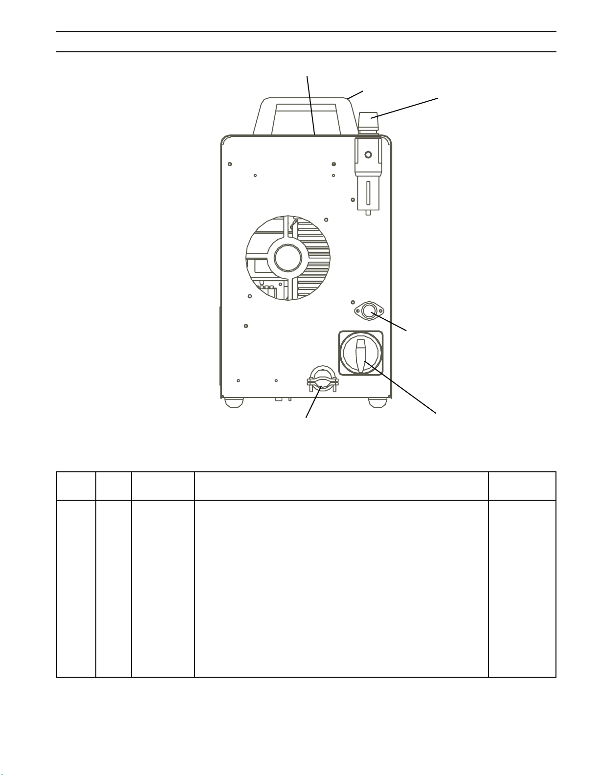
SECTION 7 REPLACEMENT PARTS
154, 155, 156, 164
153
151, 152
158, 159
162
160, 161
Figure 7-2. ESP-50 Power Source, Rear View
Item Qty. Part Circuit
No. Req. No. Description Symbol
151 1 21710 FILTER REGULATOR
152 1 10Z30 ADAPTOR B/A-WM x 1/4 NPTM
153 2 951575 HANDLE
154 1 36719YL TOP COVER YEL
155 1 2091514 LABEL WARNING
156 1 954290 LABEL WARNING
157
158 1 952136 FUSE HOLDER
159 1 952559 FUSE 3 A FAST ACTING F1
160 1 97W63 STRAIN RELIEF
161 1 37573 INPUT POWER CABLE, 6 FT (208/230 V)
1 0558001181 INPUT POWER CABLE, 10 FT (400CE/460 V)
162 1 36107 SWITCH POWER 600V 63A S1
43
Page 44
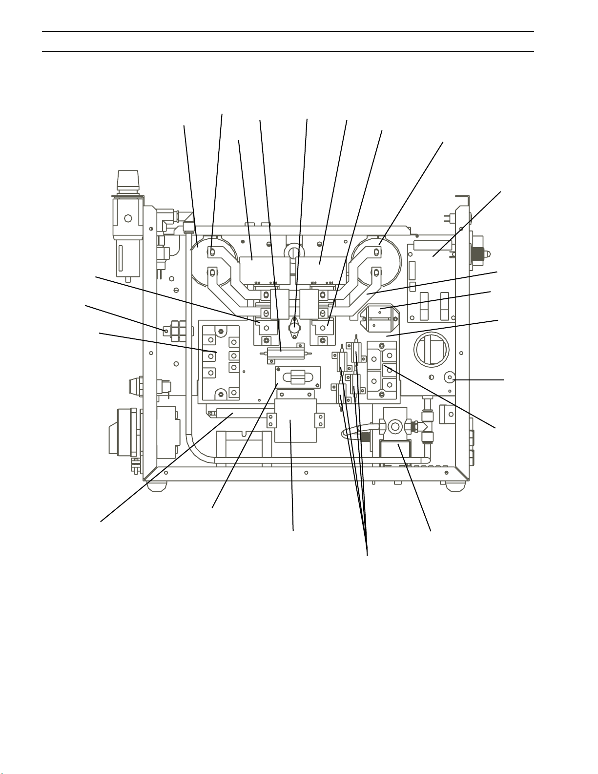
SECTION 7 REPLACEMENT PARTS
31
32, 33, 34
35
25, 26
29, 30
27
36
39
27
35
25, 26
41
24
45
43
23
46, 47
37
38
40
Figure 7-3. ESP-50 Power Source, Left Side View (208/230)
21
44
44
Page 45

SECTION 7 REPLACEMENT PARTS
Item Qty. Part Circuit
No. Req. No. Description Symbol
21 1 952150 BRIDGE 60ADC 100NS 600 V (includes PAD - 951192) D1
22 1 952002 CORE SATURABLE (Not shown - see wiring) L3
23 1 952208 STANDOFF INSULATING NYLON TB3
24 1 36731 BUSBAR NEG
25 2 952237 CAPACITOR 1800 µf 450VDC C1, 2
26 2 994674 GROMMET STRIP
27 2 0558001177 PCB ASS'Y MOSFET IGBT DRIVER BOARD PCB2, 3
28
29 1 36730 BUSBAR POS
30 1 951028 CAPACITOR 1µf 630VDC (Not shown - see wiring) C3
31 1 950487 TERM BLOCK 2 POS TB5
32 1 952235 MODULE INPUT BRIDGE/SCR (includes PAD - 952280) IBR
33 1 2062282 CAPACITOR .22µf 1KV (See wiring) C19
34 3 951321 METAL OXIDE VARISTOR 275 V (See wiring) MOV1, 2, 3
35 2 951205 IGBT 600 V 100 A (includes PAD - 951190) Q1, 2
36 1 17750010 RESISTOR 50 W 10 OHM (PAD - 951194) R7
37 1 32958 CURRENT TRANSFORMER ASS'Y T4
38 1 952255 CAPACITOR 40 µf 400 VDC C4
39 1 950711 THERMAL SWITCH 194°F TS1
40 4 17721020 RESISTOR 24 W 20 OHMS (PAD 951193) R3, 4, 5, 6
41 1 0558038258 PILOT ARC CONTROL PCB PCB4
42 2 951940 CAPACITOR 1µf 630W VDC C15, 16
43 1 952558 HEATSINK
44 1 0558004447 SOLENOID VALVE 1/4NPT NC 24 VAC SOL1
45 1 0558002436 DIODE SINGLE FAST RECOV D2
46 1 17250010 RESISTOR WW FIXED 50W 10 OHM R10
47 2 99512068 RESISTOR BRACKET
48 1 0558003105 PRESSURE SWITCH PS1
45
Page 46
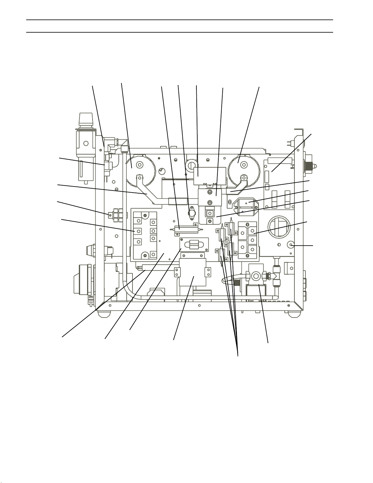
SECTION 7 REPLACEMENT PARTS
48
62
63
64, 65, 66
61
56, 57, 58
67
71
59
60
56, 57, 58
73
55
76
53
51
54
77, 78
68
74
69
75
72
Figure 7-4. ESP-50 Power Source, Left Side View (400CE/460)
46
Page 47

SECTION 7 REPLACEMENT PARTS
Item Qty. Part Circuit
No. Req. No. Description Symbol
51 1 952150 BRIDGE 60 ADC 100NS 600 V (includes PAD - 951192) D1
52 1 952002 CORE SATURABLE (Not shown - see wiring) L3
53 1 951800 MODULE DUAL IGBT 150 A, 1200 V
(includes PAD - 951191) Q1
54 1 952208 STANDOFF INSULATING NYLON TB3
55 1 36732 BUSBAR POS
56 2 952237 CAPACITOR 1800µf 450 VDC (400CE/460 V) C1, 2
2 952562 CAPACITOR 1800µf 500 VDC (575 V) C1, 2
57 2 994674 GROMMET STRIP
58 2 951028 CAPACITOR 1µf 630 VDC (See wiring) C3, 15
59 1 0558001178 PCB ASS'Y IGBT DRIVER BOARD PCB2
60 1 951964 CAPACITOR 2µf 800 VDC (400CE/460V) C16
61 1 36822 HOSE ASS'Y B/A x 1/4 NPT RUB
62 1 36733 BUSBAR NEG
63 1 950487 TERM BLOCK 2 POS TB5
64 1 952235 MODULE INPUT BRIDGE/SCR
(includes PAD - 952280) IBR
65 1 2062282 CAPACITOR .22µf 1KV C19
66 3 950591 METAL OXIDE VARISTOR 510 V (400CE/460 V) MOV1, 2, 3
67 2 17750010 RESISTOR 50W 10 OHM (PAD - 951194) R7
68 1 32958 CURRENT TRANSFORMER ASS'Y T4
69 1 952255 CAPACITOR 40µf 400 VDC (400CE/460 V) C4
70 1 058004394 INDUCTOR, PILOT ARC L4
71 1 950711 THERMAL SWITCH 194°F TS1
72 4 17721020 RESISTOR 25W 20 OHMS (PAD - 951193) R3, 4, 5, 6
73 1 0558038258 PILOT ARC CONTROL PCB PCB4
74 1 952558 HEATSINK
75 1 950249 SOLENOID VALVE 1/4 NPT 165 PSI 24 VAC SOL1
76 1 0558002436 DIODE SINGLE FAST RECOV D2
77 1 17250010 RESISTOR WW FIXED 50W 10 OHM R10
78 2 99512068 RESISTOR BRACKET
47
Page 48
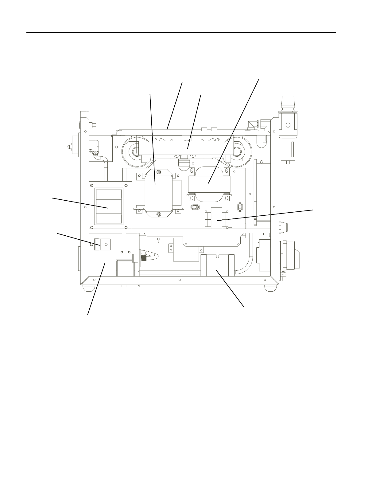
SECTION 7 REPLACEMENT PARTS
93
94
88
87
86
81
80
96
Figure 7-5. ESP-50 Power Source, Right Side View (208/230)
48
70
Page 49

SECTION 7 REPLACEMENT PARTS
Item Qty. Part Circuit
No. Req. No. Description Symbol
80 1 35940 CONTROL TRANSFORMER ASS'Y T2
81 2 17300008 RESISTOR 300W 8 OHM R11,12
82 1 0558004394 INDUCTOR, PILOT ARC L4
83
84
85 1 23604891 LABEL WARNING HI VOLTAGE RED
86 1 952232 INDUCTOR PFC L2
87 1 0558038261 CONTROL BOARD ASS'Y PCB1
88 1 0558004395 MAIN TRANSFORMER ASS'Y T1
89 2 951469 CAPACITOR .022µf 250 VAC (See Wiring) C17, 18
90
91 2 951515 CAPACITOR .047µf 660 VAC C21,C23
92
93 1 952233 INDUCTOR OUTPUT L1
94 1 36721 BUSBAR OUTPUT
95
96 1 36717 BRACKET OUTPUT
97
98
99
100
101
102 2 672348 CAPACITOR .01µf 1KV (See wiring) C11, 12
103 1 952204 CAPACITOR .01µf 250 VAC (See wiring) C9
104
105
49
Page 50
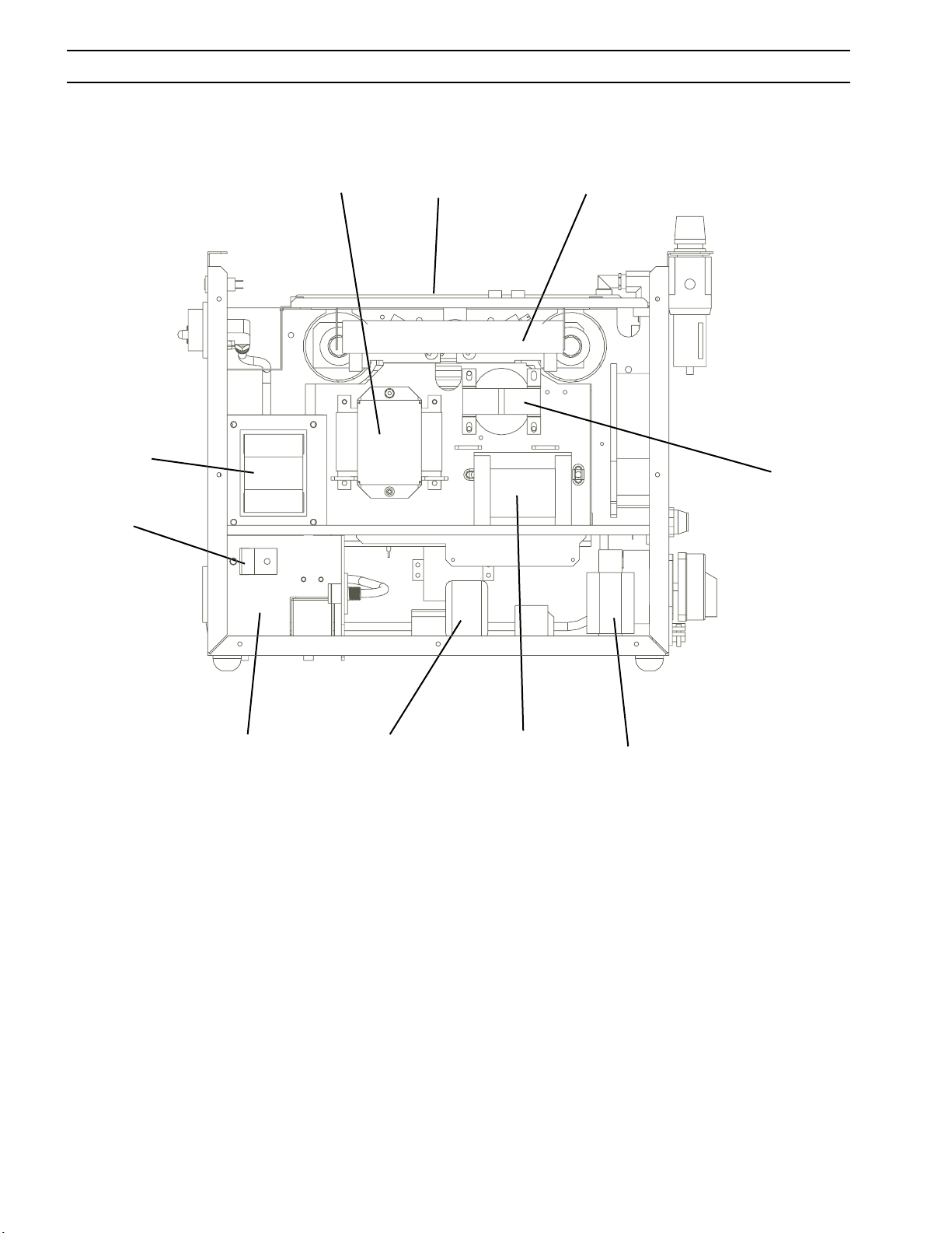
SECTION 7 REPLACEMENT PARTS
123, 135
122
117
116
111
82
125
121
110
133
Figure 7-6. ESP-50 Power Source, Right Side View (400CE/460)
50
Page 51

SECTION 7 REPLACEMENT PARTS
Item Qty. Part Circuit
No. Req. No. Description Symbol
110 1 32914 CONTROL TRANSFORMER ASS'Y T2
111 1 17300008 RESISTOR 300W 8 OHM R11,12
112
113
114
115 1 23604891 LABEL WARNING HI VOLTAGE RED
116 1 0558038261 CONTROL BOARD ASS'Y PCB1
117 1 0558004395 MAIN TRANSFORMER ASS'Y (400CE/460 V) T1
118 2 951469 CAPACITOR .022µf 250 VAC (See wiring) C17, 18
119
120 1 951515 CAPACITOR .047µf 660 VAC C23
121 1 0455803881 EMF FILTER BOARD PCB5
122 1 952233 INDUCTOR OUTPUT L1
123 1 36721 BUSBAR OUTPUT
124
125 1 36717 BRACKET OUTPUT KYDEX
126
127
128
129
130 1 950487 TERM BLOCK 2 POS 20 A TB1
131 2 672348 CAPACITOR .01µf 1KV (See wiring) C11, 12
132 1 952204 CAPACITOR .01µf 250 VAC (See wiring) C9
133 1 952213 REACTOR 3PH LINE 12 A L2
134
135 1 951314 CAPACITOR .022µf 1KV (See wiring) C20
51
Page 52
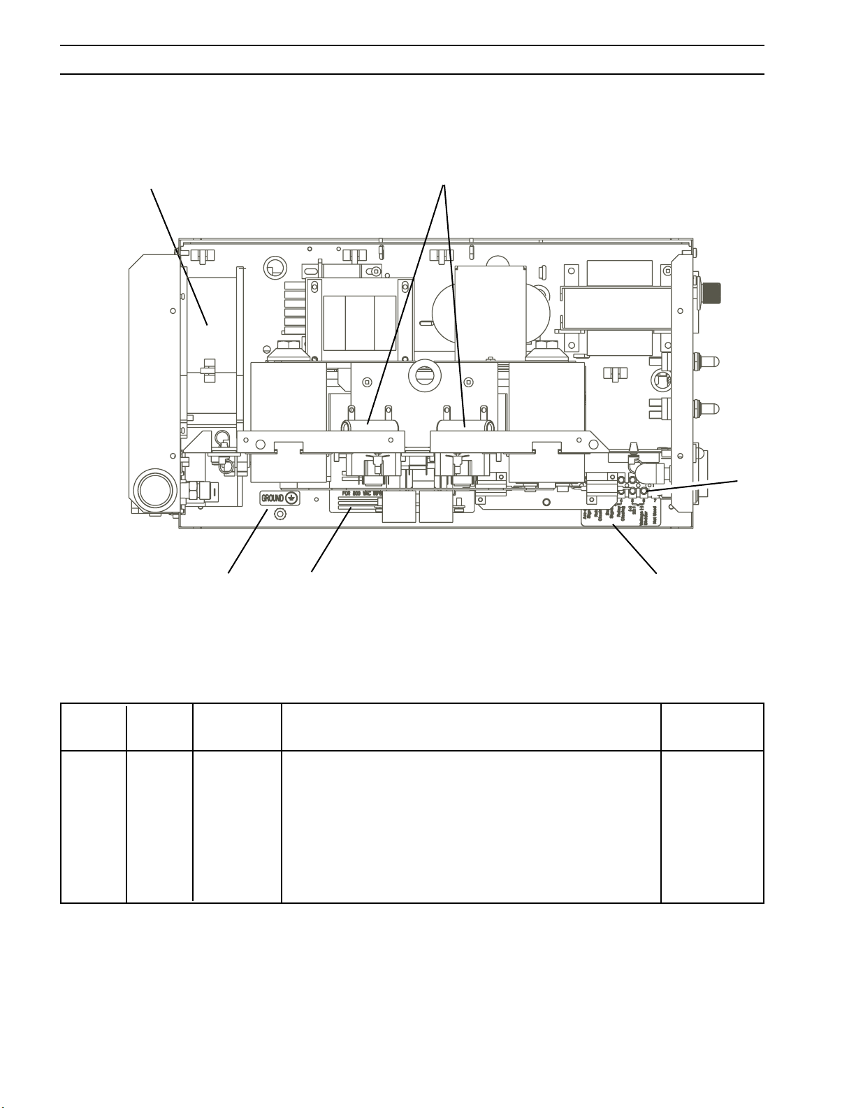
SECTION 7 REPLACEMENT PARTS
143
142
140
144
145
141
Figure 7-7. ESP-50 (208/230V) Power Source, Top View with PCB1 and Shelf Removed
Item Qty. Part Circuit
No. Req. No. Description Symbol
140 1 954673 LABEL CNC INTERFACE
141 1 952026 TERM BLOCK 7 POS 25 A TB4
142 2 17240310 RESISTOR 10 K 25 W R2, 15
143 1 951182 FAN AC AXIAL M1
144 1 2091558 LABEL GROUND BLACK
145 1 954700 LABEL INPUT (208/230 V)
1 954681 LABEL INPUT (400CE/460 V)
52
Page 53

SECTION 7 REPLACEMENT PARTS
53
Page 54

NOTES
54
Page 55

REVISION HISTORY
Original release of this manual: 02/2004.
1.
04/2004 Revision - added Pierce Height to cut data charts.
2.
01/2005 Revision - Section 2 - Chgd electrode p/n from: 0558004355 to: 0558005200 in cut
3.
data charts. Added p/n's 0558004973 & 0558004974 for ESP-50 208/230 V PT-35 packages without rack. |Updated torch specifications figure 2-1 & 2-2 drawing. Updated spare parts kits with
new p/n 0558005210, consumable value pack p/n 0558005203, consumable set p/n 0558005201
& consumable set p/n 0558005202. Section 4 - Updated figure 4-2 to show new electrode drawing. Created schematic pack (with new p/n's 0558004710 & 0558004711) for back cover insert.
Revision - 05/2005 - added Air Line Filter Regulator p/n 0558005394 note in Replacement Parts section
4.
per CN #053013.
Revision - 01/2006 - Removed filter regulator, item 151, p/n 0558005394 note, in replacement parts
5.
section per D. Smith.
55
Page 56

ESAB Welding & Cutting Products, Florence, SC Welding Equipment
COMMUNICATION GUIDE - CUSTOMER SERVICES
A. CUSTOMER SERVICE QUESTIONS:
Telephone: (800)362-7080 / Fax: (800) 634-7548 Hours: 8:00 AM to 7:00 PM EST
Order Entry Product Availability Pricing Order Information Returns
B. ENGINEERING SERVICE:
Telephone: (843) 664-4416 / Fax : (800) 446-5693 Hours: 7:30 AM to 5:00 PM EST
Warranty Returns Authorized Repair Stations Welding Equipment Troubleshooting
C. TECHNICAL SERVICE:
Telephone: (800) ESAB-123/ Fax: (843) 664-4452 Hours: 8:00 AM to 5:00 PM EST
Part Numbers Technical Applications Specifications Equipment Recommendations
D. LITERATURE REQUESTS:
Telephone: (843) 664-5562 / Fax: (843) 664-5548 Hours: 7:30 AM to 4:00 PM EST
E. WELDING EQUIPMENT REPAIRS:
Telephone: (843) 664-4487 / Fax: (843) 664-5557 Hours: 7:30 AM to 3:30 PM EST
Repair Estimates Repair Status
F. WELDING EQUIPMENT TRAINING
Telephone: (843)664-4428 / Fax: (843) 679-5864 Hours: 7:30 AM to 4:00 PM EST
Training School Information and Registrations
G. WELDING PROCESS ASSISTANCE:
Telephone: (800) ESAB-123 Hours: 7:30 AM to 4:00 PM EST
H. TECHNICAL ASST. CONSUMABLES:
Telephone : (800) 933-7070 Hours: 7:30 AM to 5:00 PM EST
IF YOU DO NOT KNOW WHOM TO CALL
Telephone: (800) ESAB-123
Fax: (843) 664-4462
Hours: 7:30 AM to 5:00 PM EST
or
visit us on the web at http://www.esabna.com
The ESAB web site offers
Comprehensive Product Information
Material Safety Data Sheets
Warranty Registration
Instruction Literature Download Library
Distributor Locator
Global Company Information
Press Releases
Customer Feedback & Support
0558004311 01 / 2006
Page 57
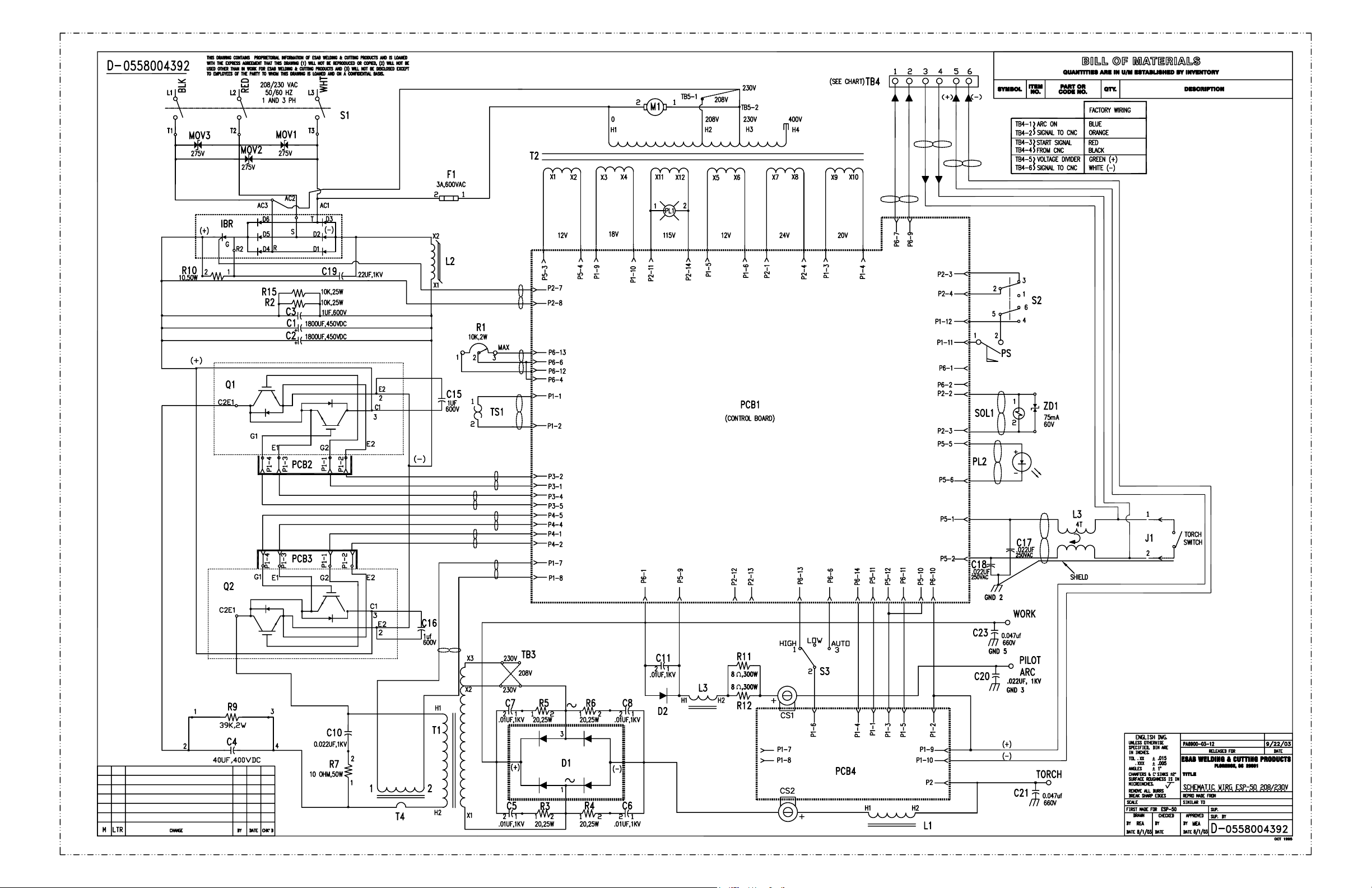
Page 58
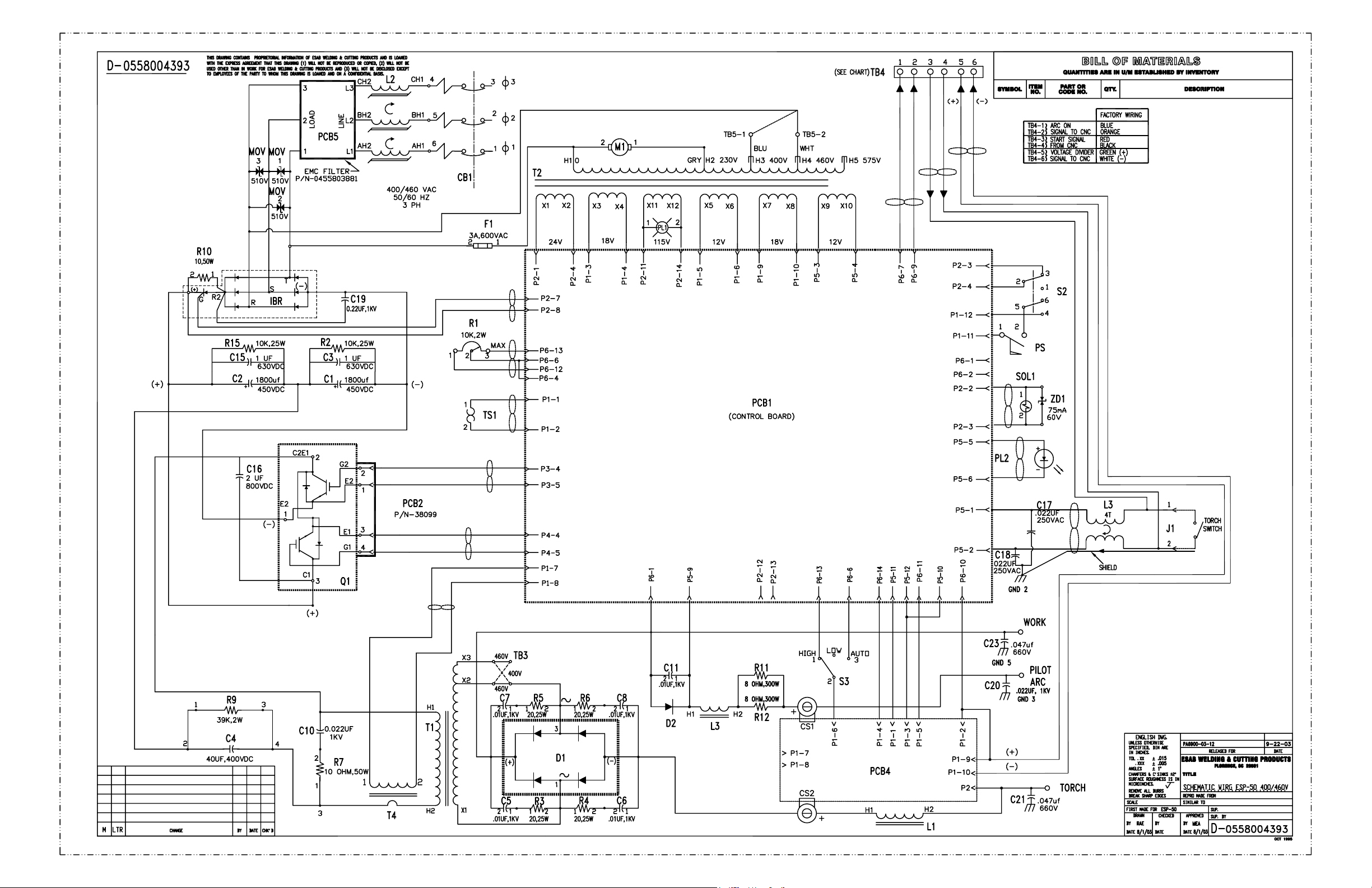
Page 59
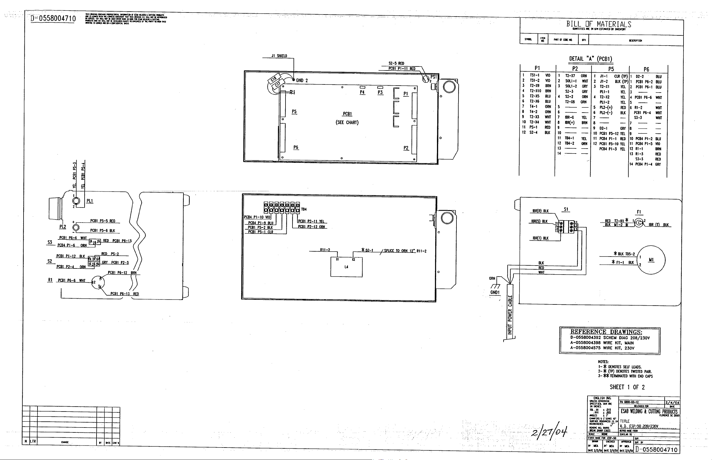
Page 60
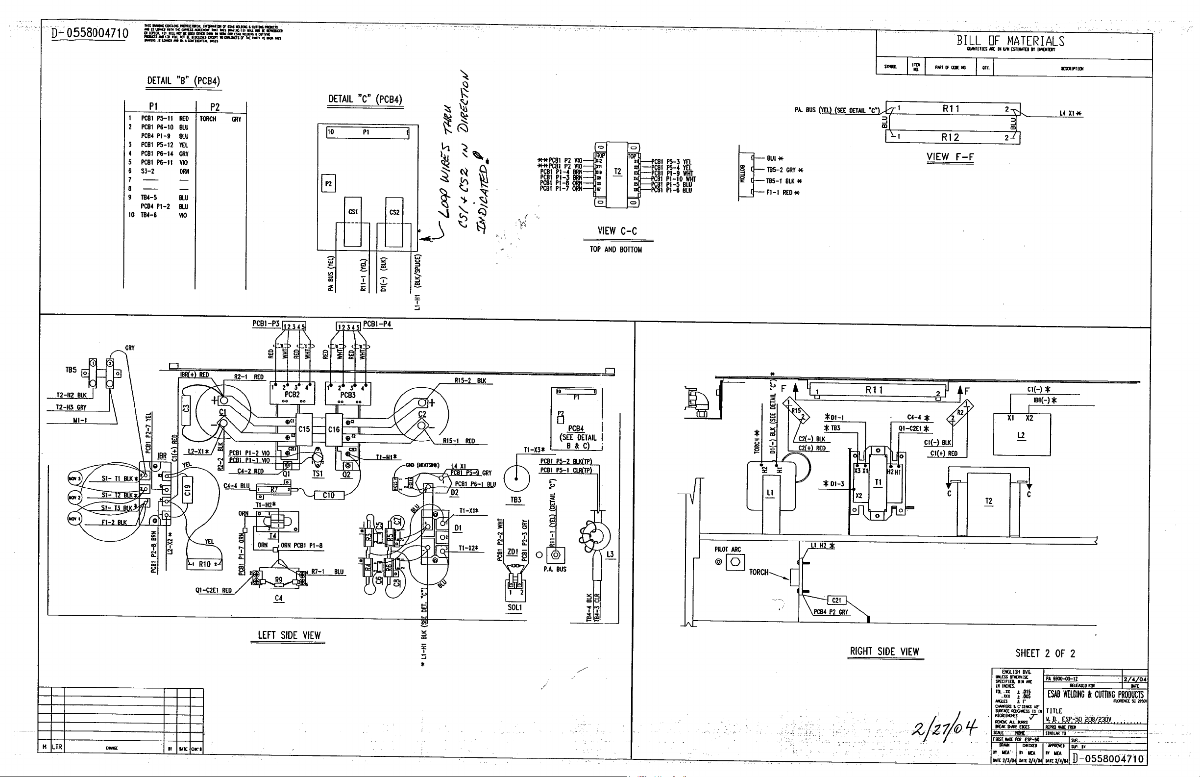
Page 61
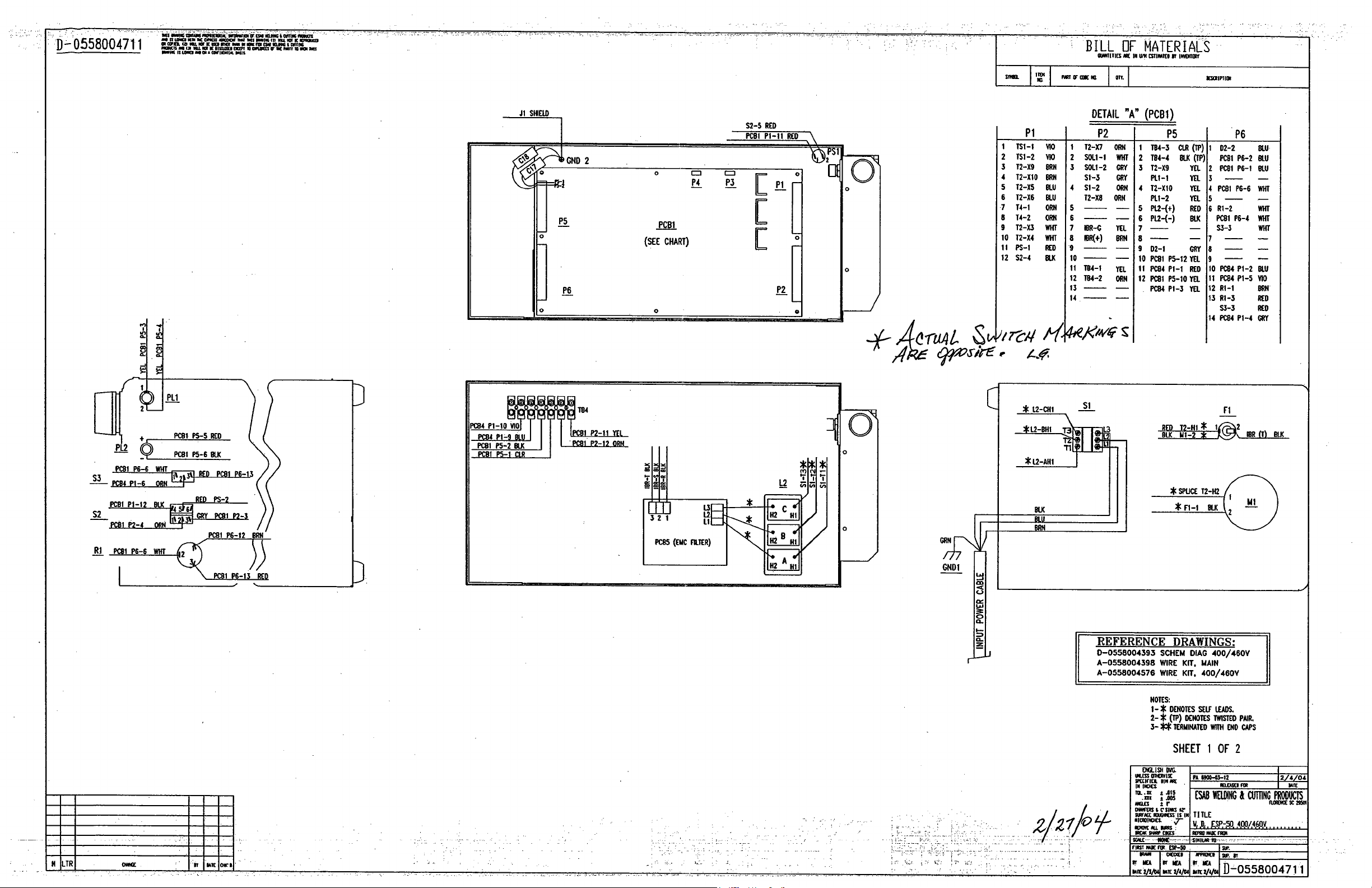
Page 62
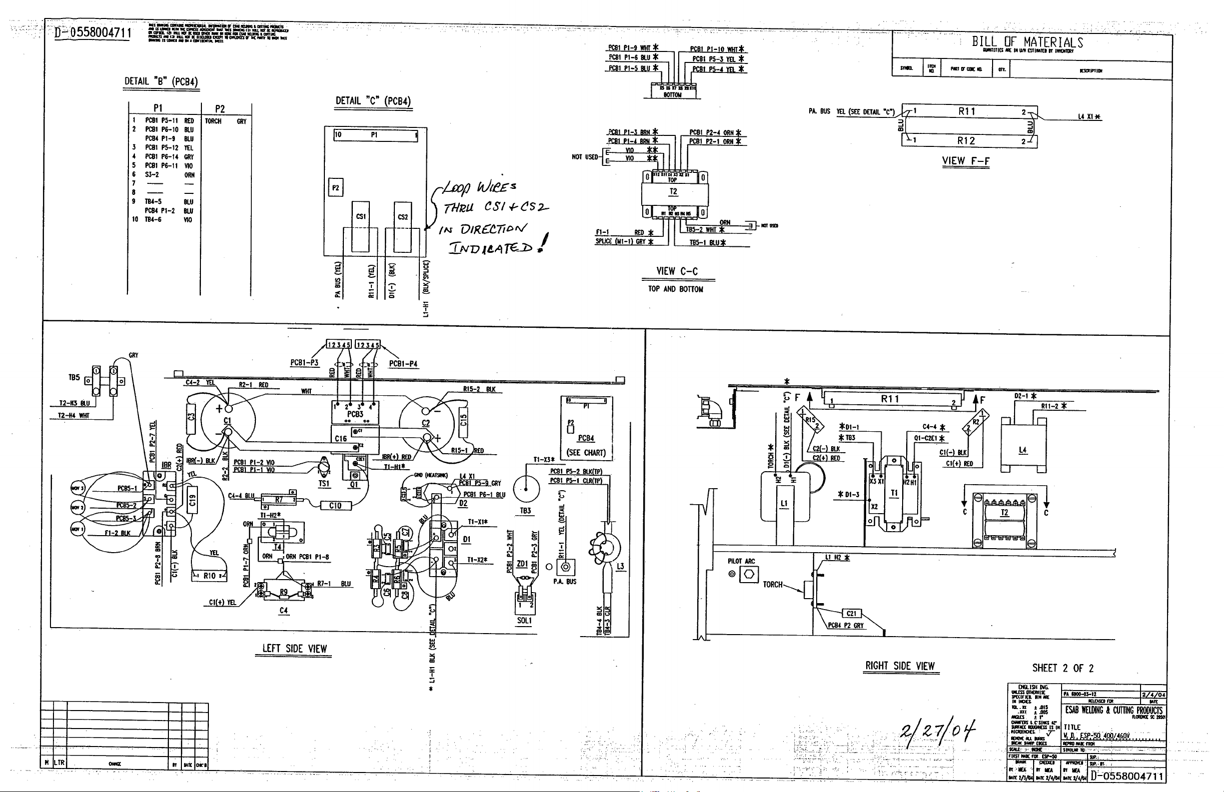
 Loading...