


Installation, Operation, and Maintenance for the
ESP-400C
Plasma Power Source
F-15-657
Jun, 2005

The equipment described in this manual is
potentially hazardous. Use caution when installing,
operating and maintaining this equipment.
Purchaser is solely responsible for the safe
operation and use of all products purchased,
including compliance with OSHA and other
government standards. ESAB Cutting
Systems has no liability for personal injury or
other damage arising out of the use of any
product manufactured or sold by ESAB. See
standard ESAB terms and conditions of sale
for a specific statement of ESAB’s
responsibilities and limitations on its liability.
ESAB Cutting Systems first priority is total
customer satisfaction. We constantly look for
ways to improve our products, service and
documentation. As a result, we make
enhancements and/or design changes as
required. ESAB makes every possible effort to
ensure our documentation is current. We
cannot guarantee that each piece of
documentation received by our customers
reflects the latest design enhancements.
Therefore, the information contained in this
document is subject to change without notice.
This manual is ESAB Part Number F15657
This manual is ESAB Part Number F15657
This manual is ESAB Part Number F15657This manual is ESAB Part Number F15657
This manual is for the convenience and use of the
cutting machine purchaser. It is not a contract or
other obligation on the part of ESAB Cutting
Systems.
©©©© ESAB Cutting Systems, 2000
Printed in U.S.A.

ESP-400C Plasma Power Source Table of Contents
Page
Section 1 Safety
1.1 Introduction 1
1.2 Safety Notations And Symbols 1
1.3 General Safety Information 2
1.4 Installation Precautions 3
1.5 Electrical Grounding 4
1.6 Operating A Plasma Cutting Machine 4-7
1.7 Service Precautions 8
1.8 Safety References 9
Section 2 Description
2.1 General 1
2.2 General Specifications 1
2.3 Dimensions and Weight 2
Section 3 Installation
3.1 General 1
3.2 Unpacking 1
3.3 Placement 2
3.4 Input Power Connections 2-5
3.4.1 Primary Power 3
3.4.2 Input Conductors 4
3.4.3 Input Connection Procedure 4-5
3.5 Output Connections 5-6
3.5.1 Output Cables 5
3.5.2 Output Connection Procedure 5
3.6 Parallel Installation 6-7
3.7 System Interconnecting Block Diagram with Smart Flow II 8
3.8 System Interconnecting Block Diagram without Smart Flow II 9
Section 4 Operation
4.1 Introduction 1
4.2 Control Panel 1-3
4.3 Sequence of Operation 4
4.4 Arc Initiation Settings 4-7
4.4.1 Enable/Disable Arc Initiation Timer 6
4.4.2 Adjusting Arc Initiation Timer 6
4.4.3 Arc Initiation Controls 7
4.4.4 Start Current and Up-slope Timer 7
4.5 V-I Curve 8
i

ESP-400C Plasma Power Source Table of Contents
Section 5 Maintenance
5.1 General 1
5.2 Cleaning 1
5.3 Fan Lubrication 2
Section 6 Troubleshooting
6.1 General 1
6.2 Fault Indicators 1-3
6.3 Fault Isolation (Diagnostics) 4-10
6.3.1 Fans 4
6.3.2 Power not on or Low Voltage 4
6.3.3 Fault Light Illumination 5-8
6.3.4 Torch will not Fire 9
6.3.5 Fuses 1 and 2 Blown 10
6.3.6 Intermittent, interrupted or Partial Operation 10-12
6.4 Testing and Replacing Components 13
6.4.1 Power Rectifiers 14
Negative Plate 14
Positive Plate 15
Electrode Plate 15
6.4.2 Freewheeling Diodes and IGBTs 16-18
6.4.3 Power Shunt Installation 18
6.4.4 Procedure for Verifying Calibration of Digital Meters 19
6.5 ESP-400C Schematic Diagrams 20-27
6.6 Wiring Diagrams 28-35
6.7 PC Controller Board (PCB1 - P/N 38032) Schematics 36-40
6.8 PCB Digital Meter Board (PCB4 – P/N 38139) Schematics 41-43
6.9 IGBT Driver Board (PCB2,3 – P/N 38030) Schematics 44-46
ii

ESP-400C Plasma Power Source Table of Contents
Section 7 Replacement Parts
7.1 General 1
7.2 Ordering 1
7.3 Outside View - Front and Back 2-3
7.4 Front View With PCBs Exposed 4-5
7.5 Right Side View 6-7
7.6 Left Side View 8-9
7.7 Top View 10-11
7.8 Back Inside View 12-13
7.9 Middle Cross Section 14-15
7.10 Front Cross Section – Behind Front Panel 16-17
Customer/Technical Information Back Manual Cover
iii

ESP-400C Plasma Power Source Table of Contents
This page intentionally left blank.
iv

SECTION 1 SAFETY
1.1 Introduction
The process of cutting metals with plasma equipment
provides industry with a valuable and versatile tool.
ESAB cutting machines are designed to provide both
operation safety and efficiency. However, as with any
machine tool, sensible attention to operating
procedures, precautions, and safe practices is
necessary to achieve a full measure of usefulness.
Whether an individual is involved with operation,
servicing, or as an observer, compliance with
established precautions and safe practices must be
accomplished. Failure to observe certain precautions
could result in serious personnel injury or severe
equipment damage. The following precautions are
general guidelines applicable when working with
cutting machines. More explicit precautions pertaining
to the basic machine and accessories are found in the
instruction literature. For a wide scope of safety
information on the field of cutting and welding
apparatus, obtain and read the publications listed in
the Recommended References.
1.2 Safety Notations And Symbols
!
DANGER
!
WARNING
!
CAUTION
!
CAUTION
The following words and symbols are used throughout
this manual. They indicate different levels of required
safety involvement.
ALERT or ATTENTION. Your safety is involved
or potential equipment failure exists. Used with
other symbols and information.
Used to call attention to immediate hazards
which, if not avoided, will result in serious
personal injury or loss of life.
Used to call attention to potential hazards
that could result in personal injury or loss of
life.
Used to call attention to hazards that could
result in minor personal injury or equipment
damage.
Used to call attention to minor hazards to
equipment.
NOTICE
Used to call attention to important
installation, operation or maintenance
information not directly related to safety
hazards.
ESP-400CPlasma Power Source
ESP-400CPlasma Power Source
ESP-400CPlasma Power SourceESP-400CPlasma Power Source
1-1

SECTION 1 SAFETY
1.3 General Safety Information
Machinery often starts automatically.
WARNING
!
This equipment moves in various directions and
This equipment moves in various directions and
This equipment moves in various directions andThis equipment moves in various directions and
speeds.
speeds.
speeds.speeds.
Moving machinery can crush.
Moving machinery can crush.
Moving machinery can crush.Moving machinery can crush.
Only qualified personnel should operate or service
Only qualified personnel should operate or service
Only qualified personnel should operate or serviceOnly qualified personnel should operate or service
this power source.
this power source.
this power source.this power source.
Keep all personnel, materials, and equipment not
Keep all personnel, materials, and equipment not
Keep all personnel, materials, and equipment notKeep all personnel, materials, and equipment not
involved in production process clear of entire
involved in production process clear of entire
involved in production process clear of entireinvolved in production process clear of entire
system area.
system area.
system area.system area.
Fence off entire work cell to prevent personnel
Fence off entire work cell to prevent personnel
Fence off entire work cell to prevent personnelFence off entire work cell to prevent personnel
from passing through area or standing in the
from passing through area or standing in the
from passing through area or standing in thefrom passing through area or standing in the
working envelope of the equipment.
working envelope of the equipment.
working envelope of the equipment.working envelope of the equipment.
Post appropriate WARNING signs at every work
Post appropriate WARNING signs at every work
Post appropriate WARNING signs at every workPost appropriate WARNING signs at every work
cell entrance.
cell entrance.
cell entrance.cell entrance.
WARNING
!
Follow lockout procedure before servicing any
Follow lockout procedure before servicing any
Follow lockout procedure before servicing anyFollow lockout procedure before servicing any
equipment.
equipment.
equipment.equipment.
Failure to follow operating instructions
could result in death or serious injury.
Read and understand this operator’s manual before
Read and understand this operator’s manual before
Read and understand this operator’s manual beforeRead and understand this operator’s manual before
using machine.
using machine.
using machine.using machine.
Read entire procedure before operating or
Read entire procedure before operating or
Read entire procedure before operating orRead entire procedure before operating or
performing any system maintenance.
performing any system maintenance.
performing any system maintenance.performing any system maintenance.
Special attention must be given to all hazard
Special attention must be given to all hazard
Special attention must be given to all hazardSpecial attention must be given to all hazard
warnings that provide essential information
warnings that provide essential information
warnings that provide essential informationwarnings that provide essential information
regarding personnel safety and/or possible
regarding personnel safety and/or possible
regarding personnel safety and/or possibleregarding personnel safety and/or possible
equipment damage.
equipment damage.
equipment damage.equipment damage.
All safety precautions relevant to electrical
All safety precautions relevant to electrical
All safety precautions relevant to electricalAll safety precautions relevant to electrical
equipment and process operations must be
equipment and process operations must be
equipment and process operations must beequipment and process operations must be
strictly observed by all having system
strictly observed by all having system
strictly observed by all having systemstrictly observed by all having system
responsibility or access.
responsibility or access.
responsibility or access.responsibility or access.
1-2
Read all safety publications made available by
Read all safety publications made available by
Read all safety publications made available byRead all safety publications made available by
your company.
your company.
your company.your company.
ESP-400CPlasma Power Source
ESP-400CPlasma Power Source
ESP-400CPlasma Power SourceESP-400CPlasma Power Source

SECTION 1 SAFETY
Failure to follow safety warning label
WARNING
!
1.4 Installation Precautions
instructions could result in death or
serious injury.
Read and understand all safety warning labels on
Read and understand all safety warning labels on
Read and understand all safety warning labels onRead and understand all safety warning labels on
machine.
machine.
machine.machine.
Refer to operator’s manual for additional safety
Refer to operator’s manual for additional safety
Refer to operator’s manual for additional safetyRefer to operator’s manual for additional safety
information.
information.
information.information.
WARNING
!
Improperly Installed Equipment Can Cause
Injury Or Death.
Follow these guidelines while installing machine:
Follow these guidelines while installing machine:
Follow these guidelines while installing machine:Follow these guidelines while installing machine:
Contact your ESAB representative before
Contact your ESAB representative before
Contact your ESAB representative beforeContact your ESAB representative before
installation. He can suggest certain precautions
installation. He can suggest certain precautions
installation. He can suggest certain precautionsinstallation. He can suggest certain precautions
regarding piping installation and machine lifting,
regarding piping installation and machine lifting,
regarding piping installation and machine lifting,regarding piping installation and machine lifting,
etc. to ensure maximum security.
etc. to ensure maximum security.
etc. to ensure maximum security.etc. to ensure maximum security.
Never attempt any machine modifications or
Never attempt any machine modifications or
Never attempt any machine modifications orNever attempt any machine modifications or
apparatus additions without first consulting a
apparatus additions without first consulting a
apparatus additions without first consulting aapparatus additions without first consulting a
qualified ESAB representative.
qualified ESAB representative.
qualified ESAB representative.qualified ESAB representative.
Observe machine clearance requirements for
Observe machine clearance requirements for
Observe machine clearance requirements forObserve machine clearance requirements for
proper operation and personnel safety.
proper operation and personnel safety.
proper operation and personnel safety.proper operation and personnel safety.
Always have qualified personnel
Always have qualified personnel perform
Always have qualified personnel Always have qualified personnel
installation, troubleshooting and maintenance of
installation, troubleshooting and maintenance of
installation, troubleshooting and maintenance ofinstallation, troubleshooting and maintenance of
this equipment.
this equipment.
this equipment.this equipment.
Provide a wall mounted disconnect switch with
Provide a wall mounted disconnect switch with
Provide a wall mounted disconnect switch withProvide a wall mounted disconnect switch with
proper fuse sizes close to the power supply.
proper fuse sizes close to the power supply.
proper fuse sizes close to the power supply.proper fuse sizes close to the power supply.
perform
performperform
ESP-400CPlasma Power Source
ESP-400CPlasma Power Source
ESP-400CPlasma Power SourceESP-400CPlasma Power Source
1-3
SECTION 1 SAFETY
1.5 Electrical Grounding
Electrical grounding is imperative for proper machine
operation and SAFETY. Refer to this manual’s
Installation section for detailed grounding instructions.
Electric shock hazard.
WARNING
!
Improper grounding can cause severe injury or death.
Improper grounding can cause severe injury or death.
Improper grounding can cause severe injury or death.Improper grounding can cause severe injury or death.
Machine must be properly grounded before put into
Machine must be properly grounded before put into
Machine must be properly grounded before put intoMachine must be properly grounded before put into
service.
service.
service.service.
1.6 Operating A Plasma Cutting Machine
WARNING
!
WARNING
!
Flying debris and loud noise hazards.
Hot spatter can burn and injure eyes. Wear
Hot spatter can burn and injure eyes. Wear
Hot spatter can burn and injure eyes. WearHot spatter can burn and injure eyes. Wear
goggles to protect eyes from burns and flying
goggles to protect eyes from burns and flying
goggles to protect eyes from burns and flyinggoggles to protect eyes from burns and flying
debris generated during operation.
debris generated during operation.
debris generated during operation.debris generated during operation.
Chipped slag may be hot and fly far. Bystanders
Chipped slag may be hot and fly far. Bystanders
Chipped slag may be hot and fly far. BystandersChipped slag may be hot and fly far. Bystanders
should also wear goggles and safety glasses.
should also wear goggles and safety glasses.
should also wear goggles and safety glasses.should also wear goggles and safety glasses.
Noise from plasma arc can damage hearing. Wear
Noise from plasma arc can damage hearing. Wear
Noise from plasma arc can damage hearing. WearNoise from plasma arc can damage hearing. Wear
correct ear protection when cutting above water.
correct ear protection when cutting above water.
correct ear protection when cutting above water.correct ear protection when cutting above water.
Burn hazard.
Hot metal can burn.
Hot metal can burn.
Hot metal can burn.Hot metal can burn.
Do not touch metal plate or parts immediately after
Do not touch metal plate or parts immediately after
Do not touch metal plate or parts immediately afterDo not touch metal plate or parts immediately after
cutting. Allow metal time to cool, or douse with
cutting. Allow metal time to cool, or douse with
cutting. Allow metal time to cool, or douse withcutting. Allow metal time to cool, or douse with
water.
water.
water.water.
Do not touch plasma torch immediately after
Do not touch plasma torch immediately after
Do not touch plasma torch immediately afterDo not touch plasma torch immediately after
cutting. Allow torch time to cool.
cutting. Allow torch time to cool.
cutting. Allow torch time to cool.cutting. Allow torch time to cool.
1-4
ESP-400CPlasma Power Source
ESP-400CPlasma Power Source
ESP-400CPlasma Power SourceESP-400CPlasma Power Source
SECTION 1 SAFETY
WARNING
!
Hazardous voltages. Electric shock
can kill.
Do NOT touch plasma torch, cutting table or cable
Do NOT touch plasma torch, cutting table or cable
Do NOT touch plasma torch, cutting table or cableDo NOT touch plasma torch, cutting table or cable
connections during plasma cutting process.
connections during plasma cutting process.
connections during plasma cutting process.connections during plasma cutting process.
Always turn power off to plasma power supplies
Always turn power off to plasma power supplies
Always turn power off to plasma power suppliesAlways turn power off to plasma power supplies
before touching or servicing plasma torch.
before touching or servicing plasma torch.
before touching or servicing plasma torch.before touching or servicing plasma torch.
Always turn power off to plasma power supplies
Always turn power off to plasma power supplies
Always turn power off to plasma power suppliesAlways turn power off to plasma power supplies
before servicing any system component.
before servicing any system component.
before servicing any system component.before servicing any system component.
Do not touch live electrical parts.
Do not touch live electrical parts.
Do not touch live electrical parts.Do not touch live electrical parts.
Keep all panels and covers in place when machine
Keep all panels and covers in place when machine
Keep all panels and covers in place when machineKeep all panels and covers in place when machine
is connected to power source.
is connected to power source.
is connected to power source.is connected to power source.
Wear insulating gloves, shoes and clothing to
Wear insulating gloves, shoes and clothing to
Wear insulating gloves, shoes and clothing toWear insulating gloves, shoes and clothing to
insulate yourself from
insulate yourself from workpiece and electrical
insulate yourself from insulate yourself from
ground.
ground.
ground.ground.
Keep gloves, shoes, clothing, work area, and
Keep gloves, shoes, clothing, work area, and
Keep gloves, shoes, clothing, work area, andKeep gloves, shoes, clothing, work area, and
equipment dry.
equipment dry.
equipment dry.equipment dry.
Replace worn or damaged cables.
Replace worn or damaged cables.
Replace worn or damaged cables.Replace worn or damaged cables.
workpiece and electrical
workpiece and electricalworkpiece and electrical
WARNING
!
Fume hazard.
Fumes and gases generated by the plasma cutting
Fumes and gases generated by the plasma cutting
Fumes and gases generated by the plasma cuttingFumes and gases generated by the plasma cutting
process can be hazardous to your health.
process can be hazardous to your health.
process can be hazardous to your health.process can be hazardous to your health.
Do NOT breathe fumes.
Do NOT breathe fumes.
Do NOT breathe fumes.Do NOT breathe fumes.
Do not operate plasma torch without fume removal
Do not operate plasma torch without fume removal
Do not operate plasma torch without fume removalDo not operate plasma torch without fume removal
system operating properly.
system operating properly.
system operating properly.system operating properly.
Use additional ventilation to remove fumes if
Use additional ventilation to remove fumes if
Use additional ventilation to remove fumes ifUse additional ventilation to remove fumes if
necessary.
necessary.
necessary.necessary.
Use approved respirator if ventilation is not
Use approved respirator if ventilation is not
Use approved respirator if ventilation is notUse approved respirator if ventilation is not
adequate.
adequate.
adequate.adequate.
Provide positive mechanical ventilation when
Provide positive mechanical ventilation when
Provide positive mechanical ventilation whenProvide positive mechanical ventilation when
cutting galvanized steel, stainless steel, copper,
cutting galvanized steel, stainless steel, copper,
cutting galvanized steel, stainless steel, copper,cutting galvanized steel, stainless steel, copper,
zinc, beryllium, or cadmium. Do not breathe these
zinc, beryllium, or cadmium. Do not breathe these
zinc, beryllium, or cadmium. Do not breathe thesezinc, beryllium, or cadmium. Do not breathe these
fumes.
fumes.
fumes.fumes.
Do not operate near degreasing and spraying
Do not operate near degreasing and spraying
Do not operate near degreasing and sprayingDo not operate near degreasing and spraying
operations. Heat or arc rays can react with
operations. Heat or arc rays can react with
operations. Heat or arc rays can react withoperations. Heat or arc rays can react with
chlorinated hydrocarbon vapors to form phosgene,
chlorinated hydrocarbon vapors to form phosgene,
chlorinated hydrocarbon vapors to form phosgene,chlorinated hydrocarbon vapors to form phosgene,
a highly toxic gas and other irritant gases.
a highly toxic gas and other irritant gases.
a highly toxic gas and other irritant gases.a highly toxic gas and other irritant gases.
ESP-400CPlasma Power Source
ESP-400CPlasma Power Source
ESP-400CPlasma Power SourceESP-400CPlasma Power Source
1-5
SECTION 1 SAFETY
WARNING
!
Radiation hazard.
Arc rays can injure eyes and burn
Arc rays can injure eyes and burn skin.
Arc rays can injure eyes and burn Arc rays can injure eyes and burn
Wear correct eye and body protection.
Wear correct eye and body protection.
Wear correct eye and body protection.Wear correct eye and body protection.
Wear dark safety glasses or goggles with
Wear dark safety glasses or goggles with side
Wear dark safety glasses or goggles with Wear dark safety glasses or goggles with
shields. Refer to following chart for recommended
shields. Refer to following chart for recommended
shields. Refer to following chart for recommendedshields. Refer to following chart for recommended
lens shades for plasma cutting:
lens shades for plasma cutting:
lens shades for plasma cutting:lens shades for plasma cutting:
Arc Current
Arc Current Lens Shade
Arc CurrentArc Current
Up to 100 Amps
Up to 100 Amps Shade No. 8
Up to 100 AmpsUp to 100 Amps
100-200 Amps
100-200 AmpsShade No. 10
100-200 Amps100-200 Amps
200-400 Amps
200-400 AmpsShade No. 12
200-400 Amps200-400 Amps
Over 400 Amps
Over 400 Amps Shade No. 14
Over 400 AmpsOver 400 Amps
Replace glasses/goggles when lenses are pitted or
Replace glasses/goggles when lenses are pitted or
Replace glasses/goggles when lenses are pitted orReplace glasses/goggles when lenses are pitted or
broken
broken
brokenbroken
Warn others in area not to look directly at the arc
Warn others in area not to look directly at the arc
Warn others in area not to look directly at the arcWarn others in area not to look directly at the arc
unless wearing appropriate safety glasses.
unless wearing appropriate safety glasses.
unless wearing appropriate safety glasses.unless wearing appropriate safety glasses.
Prepare cutting area to reduce reflection and
Prepare cutting area to reduce reflection and
Prepare cutting area to reduce reflection andPrepare cutting area to reduce reflection and
transmission of ultraviolet light.
transmission of ultraviolet light.
transmission of ultraviolet light.transmission of ultraviolet light.
§ Use special paint on walls to absorb UV
Use special paint on walls to absorb UV
Use special paint on walls to absorb UVUse special paint on walls to absorb UV
light.
light.
light.light.
Lens Shade
Lens Shade Lens Shade
Shade No. 10
Shade No. 10Shade No. 10
Shade No. 12
Shade No. 12Shade No. 12
skin.
skin.skin.
Shade No. 8
Shade No. 8Shade No. 8
Shade No. 14
Shade No. 14Shade No. 14
side
sideside
WARNING
!
§ Install protective screens or curtains to
Install protective screens or curtains to
Install protective screens or curtains toInstall protective screens or curtains to
reduce ultraviolet transmission.
reduce ultraviolet transmission.
reduce ultraviolet transmission.reduce ultraviolet transmission.
Burn Hazard.
Heat, spatter, and sparks cause fire and burns.
Heat, spatter, and sparks cause fire and burns.
Heat, spatter, and sparks cause fire and burns.Heat, spatter, and sparks cause fire and burns.
Do not cut near combustible material.
Do not cut near combustible material.
Do not cut near combustible material.Do not cut near combustible material.
Do not have on your person any combustibles (e.g.
Do not have on your person any combustibles (e.g.
Do not have on your person any combustibles (e.g.Do not have on your person any combustibles (e.g.
butane lighter).
butane lighter).
butane lighter).butane lighter).
Pilot arc can cause burns. Keep torch nozzle
Pilot arc can cause burns. Keep torch nozzle
Pilot arc can cause burns. Keep torch nozzlePilot arc can cause burns. Keep torch nozzle
away from yourself and others when activating
away from yourself and others when activating
away from yourself and others when activatingaway from yourself and others when activating
plasma process.
plasma process.
plasma process.plasma process.
Wear correct eye and body protection.
Wear correct eye and body protection.
Wear correct eye and body protection.Wear correct eye and body protection.
Wear gauntlet gloves, safety shoes and hat.
Wear gauntlet gloves, safety shoes and hat.
Wear gauntlet gloves, safety shoes and hat.Wear gauntlet gloves, safety shoes and hat.
Wear flame-retardant clothing covering all exposed
Wear flame-retardant clothing covering all exposed
Wear flame-retardant clothing covering all exposedWear flame-retardant clothing covering all exposed
areas.
areas.
areas.areas.
Wear
Wear cuffless trousers to prevent entry of sparks
cuffless trousers to prevent entry of sparks
Wear Wear
cuffless trousers to prevent entry of sparkscuffless trousers to prevent entry of sparks
and slag.
and slag.
and slag.and slag.
1-6
Have
Have fire extinguishing equipment available for use.
fire extinguishing equipment available for use.
Have Have
fire extinguishing equipment available for use.fire extinguishing equipment available for use.
ESP-400CPlasma Power Source
ESP-400CPlasma Power Source
ESP-400CPlasma Power SourceESP-400CPlasma Power Source

SECTION 1 SAFETY
WARNING
!
Explosion hazard.
Certain molten aluminum-lithium (Al-
Certain molten aluminum-lithium (Al-Li) alloys can
Certain molten aluminum-lithium (Al-Certain molten aluminum-lithium (Alcause explosions when plasma cut OVER water.
cause explosions when plasma cut OVER water.
cause explosions when plasma cut OVER water.cause explosions when plasma cut OVER water.
§ These alloys should only be dry cut on a dry
These alloys should only be dry cut on a dry
These alloys should only be dry cut on a dryThese alloys should only be dry cut on a dry
table.
table.
table.table.
§ DO NOT dry cut over water.
DO NOT dry cut over water.
DO NOT dry cut over water.DO NOT dry cut over water.
§ Contact your aluminum supplier for
Contact your aluminum supplier for
Contact your aluminum supplier forContact your aluminum supplier for
additional safety information regarding
additional safety information regarding
additional safety information regardingadditional safety information regarding
hazards associated with these alloys
hazards associated with these alloys
hazards associated with these alloyshazards associated with these alloys
Do not cut in atmospheres containing explosive
Do not cut in atmospheres containing explosive
Do not cut in atmospheres containing explosiveDo not cut in atmospheres containing explosive
dust or vapors.
dust or vapors.
dust or vapors.dust or vapors.
Do not carry any combustibles on your person
Do not carry any combustibles on your person
Do not carry any combustibles on your personDo not carry any combustibles on your person
(e.g. butane lighter)
(e.g. butane lighter)
(e.g. butane lighter)(e.g. butane lighter)
Do not cut containers that have held combustibles.
Do not cut containers that have held combustibles.
Do not cut containers that have held combustibles.Do not cut containers that have held combustibles.
Li) alloys can
Li) alloys canLi) alloys can
.
ESP-400CPlasma Power Source
ESP-400CPlasma Power Source
ESP-400CPlasma Power SourceESP-400CPlasma Power Source
1-7
SECTION 1 SAFETY
1.7 Service Precautions
WARNING
!
Hazardous voltages. Electric shock
can kill.
Do NOT touch plasma torch, cutting table or cable
Do NOT touch plasma torch, cutting table or cable
Do NOT touch plasma torch, cutting table or cableDo NOT touch plasma torch, cutting table or cable
connections during plasma cutting process.
connections during plasma cutting process.
connections during plasma cutting process.connections during plasma cutting process.
Always turn power off to plasma power supplies
Always turn power off to plasma power supplies
Always turn power off to plasma power suppliesAlways turn power off to plasma power supplies
before touching or servicing plasma torch.
before touching or servicing plasma torch.
before touching or servicing plasma torch.before touching or servicing plasma torch.
Always turn power off to plasma power supplies
Always turn power off to plasma power supplies
Always turn power off to plasma power suppliesAlways turn power off to plasma power supplies
before removing covers or panels to service any
before removing covers or panels to service any
before removing covers or panels to service anybefore removing covers or panels to service any
system component.
system component.
system component.system component.
Do not touch live electrical parts.
Do not touch live electrical parts.
Do not touch live electrical parts.Do not touch live electrical parts.
Keep all panels and covers in place when machine
Keep all panels and covers in place when machine
Keep all panels and covers in place when machineKeep all panels and covers in place when machine
is connected to power source.
is connected to power source.
is connected to power source.is connected to power source.
Keep gloves, shoes, clothing, work area, and
Keep gloves, shoes, clothing, work area, and
Keep gloves, shoes, clothing, work area, andKeep gloves, shoes, clothing, work area, and
equipment dry.
equipment dry.
equipment dry.equipment dry.
Inspect power and ground leads cables for wear or
Inspect power and ground leads cables for wear or
Inspect power and ground leads cables for wear orInspect power and ground leads cables for wear or
cracking. Replace worn or damaged cables. Do
cracking. Replace worn or damaged cables. Do
cracking. Replace worn or damaged cables. Docracking. Replace worn or damaged cables. Do
not use if damaged.
not use if damaged.
not use if damaged.not use if damaged.
Never bypass safety interlocks.
Never bypass safety interlocks.
Never bypass safety interlocks.Never bypass safety interlocks.
CAUTION
CAUTION
!
Follow
Follow lock-out procedures.
Follow Follow
Establish and adhere to preventive maintenance. A
Establish and adhere to preventive maintenance. A
Establish and adhere to preventive maintenance. AEstablish and adhere to preventive maintenance. A
composite program can be established from
composite program can be established from
composite program can be established fromcomposite program can be established from
recommended schedules.
recommended schedules.
recommended schedules.recommended schedules.
Avoid leaving test equipment or hand tools on
Avoid leaving test equipment or hand tools on
Avoid leaving test equipment or hand tools onAvoid leaving test equipment or hand tools on
machine. Severe electrical or mechanical damage
machine. Severe electrical or mechanical damage
machine. Severe electrical or mechanical damagemachine. Severe electrical or mechanical damage
could occur to equipment or machine.
could occur to equipment or machine.
could occur to equipment or machine.could occur to equipment or machine.
Extreme caution should be used when probing
Extreme caution should be used when probing
Extreme caution should be used when probingExtreme caution should be used when probing
circuitry with an oscilloscope or voltmeter. Integrated
circuitry with an oscilloscope or voltmeter. Integrated
circuitry with an oscilloscope or voltmeter. Integratedcircuitry with an oscilloscope or voltmeter. Integrated
circuits are susceptible to over voltage damage.
circuits are susceptible to over voltage damage.
circuits are susceptible to over voltage damage.circuits are susceptible to over voltage damage.
Power off before using test probes to prevent
Power off before using test probes to prevent
Power off before using test probes to preventPower off before using test probes to prevent
accidental shorting of components.
accidental shorting of components.
accidental shorting of components.accidental shorting of components.
All circuit boards securely seated in sockets, all cables
All circuit boards securely seated in sockets, all cables
All circuit boards securely seated in sockets, all cablesAll circuit boards securely seated in sockets, all cables
properly connected, all cabinets closed and locked, all
properly connected, all cabinets closed and locked, all
properly connected, all cabinets closed and locked, allproperly connected, all cabinets closed and locked, all
guards and covers replaced before power is turned
guards and covers replaced before power is turned
guards and covers replaced before power is turnedguards and covers replaced before power is turned
on.
on.
on.on.
lock-out procedures.
lock-out procedures.lock-out procedures.
1-8
ESP-400CPlasma Power Source
ESP-400CPlasma Power Source
ESP-400CPlasma Power SourceESP-400CPlasma Power Source

SECTION 1 SAFETY
1.8 Safety References
The following nationally recognized publications on safety in welding
and cutting operations are recommended. These publications have
been prepared to protect persons from injury or illness and to protect
property from damage, which could result from unsafe practices.
Although some of these publications are not related specifically to this
type of industrial cutting apparatus, the principles of safety apply
equally.
“Precautions and Safe Practices in Welding and Cutting with
Oxygen-Fuel Gas Equipment,” Form 2035. ESAB Cutting
Systems.
“Precautions and Safe Practices for Electric Welding and Cutting,”
Form 52-529. ESAB Cutting Systems.
“Safety in Welding and Cutting” - ANSI Z 49.1, American Welding
Society, 2501 NW 7th Street, Miami, Florida, 33125.
“Recommended Safe Practices for Shielded Gases for Welding and
Plasma Arc Cutting” - AWS C5.10-94, American Welding Society.
“Recommended Practices for Plasma Arc Welding” - AWS C5.1,
American Welding Society.
“Recommended Practices for Arc Cutting” - AWS C5.2, American
Welding Society.
“Safe Practices” - AWS SP, American Welding Society.
“Standard for Fire Protection in Use of Cutting and Welding
Procedures” - NFPA 51B, National Fire Protection Association, 60
Batterymarch Street, Boston, Massachusetts, 02110.
“Standard for Installation and Operation of Oxygen - Fuel Gas
Systems for Welding and Cutting” - NFPA 51, National Fire
Protection Association.
“Safety Precautions for Oxygen, Nitrogen, Argon, Helium, Carbon
Dioxide, Hydrogen, and Acetylene,” Form 3499. ESAB Cutting
Systems. Obtainable through your ESAB representative or local
distributor.
"Design and Installation of Oxygen Piping Systems," Form 5110.
ESAB Cutting Systems.
“Precautions for Safe Handling of Compressed Gases in
Cylinders”, CGA Standard P-1, Compressed Gas Association.
Literature applicable to safe practices in welding and cutting with
gaseous materials is also available from the Compressed Gas
Association, Inc., 500 Fifth Ave., New York, NY 10036.
ESP-400CPlasma Power Source
ESP-400CPlasma Power Source
ESP-400CPlasma Power SourceESP-400CPlasma Power Source
1-9

SECTION 1 SAFETY
This page intentionally left blank.
1-10
ESP-400CPlasma Power Source
ESP-400CPlasma Power Source
ESP-400CPlasma Power SourceESP-400CPlasma Power Source
SECTION 2 Description
2.1 Introduction
The ESP power Source is designed for high speed
plasma mechanized cutting applications. It can be
used with other ESAB products such as the PT-15
and PT-600 torches along with the Smart Flow II, a
computerized gas regulation and switching system.
50 to 400 Amperes cutting current range
Forced air cooled
Solid state DC power
Input voltage protection
Local or remote front panel control
Thermal switch protection for main transformer
and power semiconductor components
Top lifting rings or base forklift clearance for
transport
2.2 General Specifications
Part Number
Part Number 0558001730
Part NumberPart Number
Voltage
Voltage
VoltageVoltage
Current range
Current range
Current rangeCurrent range
DC
OUTPUT (100
OUTPUT (100
OUTPUT (100OUTPUT (100
% duty cycle)
% duty cycle)
% duty cycle)% duty cycle)
INPUT
INPUT
INPUTINPUT
DC
DCDC
Power
Power
PowerPower
Open Circuit
Open Circuit
Open CircuitOpen Circuit
Voltage (OCV)
Voltage (OCV)
Voltage (OCV)Voltage (OCV)
Voltage
Voltage
VoltageVoltage
(3-phase)
(3-phase)
(3-phase)(3-phase)
Current
Current
CurrentCurrent
(3- phase)
(3- phase)
(3- phase)(3- phase)
Frequency
Frequency
FrequencyFrequency
KVA
KVA
KVAKVA
Parallel secondary power source capabilities to
extend current output range.
ESP-400C 400V,
ESP-400C 400V,
ESP-400C 400V,ESP-400C 400V,
50Hz
50Hz
CE
CE
50Hz 50Hz
CECE
0558001730 0558001729
05580017300558001730
410 V dc 427 V dc 427 V dc
400 V 460 V 575 V
138 A RMS 120 A RMS 96 A RMS
50/60 HZ 60 Hz 60 Hz
95.6 KVA 95.6 KVA 95.6 KVA
ESP-400C 460V,
ESP-400C 460V,
ESP-400C 460V,ESP-400C 460V,
60Hz
60Hz
60Hz60Hz
0558001729 0558001731
05580017290558001729
ESP-400C 575V,
ESP-400C 575V,
ESP-400C 575V,ESP-400C 575V,
60Hz
60Hz
60Hz60Hz
0558001731
05580017310558001731
200 V dc
50A to 400A
80 KW
Power
Power
PowerPower
Power Factor
Power Factor
Power FactorPower Factor
Input Fuse
Input Fuse
Input FuseInput Fuse
Rec.
Rec.
Rec.Rec.
87 KW 87 KW 87 KW
91.0 %
200A 150A 125A
ESP 400C Plasma Power Source
ESP 400C Plasma Power Source
ESP 400C Plasma Power SourceESP 400C Plasma Power Source
2-1

SECTION 2 Description
3
2.3 Dimensions and Weight
40.25 inches
102.2 mm
45 inches
mm
114.
37.25 inches
94.6 mm
Weight = 2040 lbs.
(925.34 kg.)
2-2
ESP 400C Plasma Power Source
ESP 400C Plasma Power Source
ESP 400C Plasma Power SourceESP 400C Plasma Power Source

SECTION 3 Installation
3.1 General
WARNING
!
Failure To Follow Instructions Could
Lead To Death, Injury Or Damaged
Property
Follow these instructions to prevent injury
or property damage.
You must comply with local, state and
national electrical and safety codes.
3.2 Unpacking
CAUTION
Using One Lifting Eye Will Damage
Sheet Metal And Frame
Use both lifting eyes when transporting
with overhead method.
600C
Unit weighs over 2000 lbs. Use approved
straps or cables in good condition.
• Inspect for transit damage immediately upon
receipt.
• Remove all components from shipping
container and check for loose parts in container.
• Inspect louvers for air obstructions.
ESP-400C Plasma Power Source
3-1

SECTION 3 Installation
3.3 Placement
Note: Use both lifting eyes when transporting
from overhead.
• A minimum of 2 ft. clearance on front and back
for cooling air flow.
Power
Source
• Plan for top panel and side panels having to be
removed for maintenance, cleaning and
inspection.
• Locate the ESP-400C relatively close to a
properly fused electrical power supply.
• Keep area beneath power source clear for
cooling air flow.
• Environment should be relatively free of dust,
fumes and excessive heat. These factors will
affect cooling efficiency.
Conductive Dust And Dirt Inside
CAUTION
Power Source May Cause Arc FlashOver
Equipment damage may occur. Electrical
shorting may occur if dust is allowed to build-up
inside power source. See maintenance section.
3.4 Input Power Connection
WARNING
!
Electric Shock Can Kill!
Provide maximum protection against
electrical shock.
Before any connections are made inside
the machine, open the line wall disconnect
switch to turn power off.
3-2
ESP-400C Plasma Power Source

SECTION 3 Installation
3.4.1 Primary Power
ESP-400C is a 3-phase unit. Input power must be
Rated Load
Volts Amperes
400
*Sizes per National Electrical Code for a 90 °C rated
provided from a line (wall) disconnect switch that
contains fuses or circuit breakers in accordance to
local or state regulations.
Recommended input conductor and line fuse sizes:
Input and
Ground
conductor*
CU/AWG
138
460
575
copper conductors @ 40 °C ambient. Not more than
three conductors in raceway or cable. Local codes
should be followed if they specify sizes other than those
120
96
listed above.
4/0
3/0
1/0
Time delay
Fuse size
(amperes)
200
150
125
Input current =
(V arc) x (I arc) x 0.688
(V line)
Dedicated power line may be necessary.
NOTICE
ESP-400C is equipped with line voltage
compensation but to avoid impaired performance
due to an overloaded circuit, a dedicated power
line may be required.
ESP-400C Plasma Power Source
3-3

SECTION 3 Installation
3.4.2 Input Conductors
NOTICE
3.4.3 Input Connection Procedure
• Customer supplied
• May consist either of heavy rubber covered
copper conductors (three power and one
ground) or run in solid or flexible conduit.
• Sized according to the chart.
Input conductors must be terminated with
ring terminals.
Input conductors must be terminated with ring
terminals sized for ½" hardware before being
attached to the ESP-400C.
1
3
1 Primary Terminals
2 Chassis Ground
3 Power Input Cable Access Opening (Rear Panel)
2
1. Remove left side panel of the ESP-400C
2. Thread cables through the access opening in
the rear panel.
3. Secure cables with a strain relief or conduit
coupling (not supplied) at the access opening.
4. Connect the ground lead to the stud on the
chassis base.
5. Connect the power lead ring terminals to the
primary terminals with supplied bolts, washers
and nuts.
6. Connect the input conductors to the line (wall)
disconnect.
3-4
ESP-400C Plasma Power Source

SECTION 3 Installation
WARNING
!
WARNING
!
Electric Shock Can Kill!
Ring terminals must have clearance between
side panel and main transformer. Clearance
must be sufficient to prevent possible arcing
Make sure cables do not interfere with cooling
fan rotation.
Improper Grounding Can Result In
Death or Injury.
Chassis must be connected to an approved
electrical ground.
Be sure ground lead is NOT connected to any
primary terminal.
3.5 Output Connections
WARNING
!
3.5.1 Output Cables (customer supplied)
Electric Shock Can Kill! Dangerous
Voltage And Current!
Any time working around a plasma power
source with covers removed:
• Disconnect power source at the line(wall)
disconnect.
• Have a qualified person check the output
bus bars (positive and negative) with a
voltmeter.
Choose plasma cutting output cables (customer
supplied) on the basis of one 4/0 AWG, 600 volt
insulated copper cable for each 400 amps of output
current.
Note: Do not use 100 volt insulated welding
cable.
ESP-400C Plasma Power Source
3-5

SECTION 3 Installation
3.5.2 Output Connection Procedure
Access Panel
1. Remove access panel on the lower front of the
power source.
2. Thread output cables through the openings at
the bottom of the front panel or at the bottom of
the power source immediately behind the front
panel.
3. Connect cables to designated terminals
mounted inside the power source using UL
listed pressure wire connectors.
4. Replace panel removed during the first step.
3.6 Parallel Installation
Two 400A power sources may be connected
together to extend the output current range.
Parallel power source start currents
CAUTION
exceed recommended amounts when
cutting below 100A.
Use Only One Power Source For Currents
Below 100A.
We recommend disconnecting the negative
lead from the secondary power source when
changing to currents below 100 amperes.
This lead should be safely terminated to
protect against electric shock.
3-6
ESP-400C Plasma Power Source

SECTION 3 Installation
x
g
)
Connections for Parallel Installation
of 2 Power sources
Secondary Power
Source
work
(+)
3 - 4/0 600V
positive
leads
to
workpiece
electrode
(-)
4/0 600V
Cable jumpers
between units
Primary Power
work
(+)
1 - 14 AWG 600V
lead to pilot arc
connection in
plumbing box
(h.f. generator)
Source
pilot arc
electrode
3 - 4/0 600V
negative
leads in
plumbing
box (h.f.
(-)
enerator
WARNING
!
Secondary Power
Source
work
(+)
3 - 4/0 600V
positive leads to
workpiece
electrode
(-)
Disconnect
negative
connection from
secondary power source
and insulate to
convert from two
to one power
sources
Primary Power
Source
work
(+)
negative leads
to plumbing bo
electrode
(-)
3 - 4/0 600V
(high freq.
generator)
ESP-400C Plasma Power Source
Note: Primary power source has the electrode
(-) conductor jumpered. The secondary power
source has the work (+) jumpered.
1. Connect the negative (-) output cables to the
plumbing box (high frequency generator).
2. Connect the positive (+) output cables to the
workpiece.
3. Connect the positive (+) and negative (-)
conductors between the power sources.
4. Connect the pilot arc cable to the pilot arc
terminal in the primary power source. The pilot
arc connection in the secondary power source
is not used. The pilot arc circuit is not run in
parallel.
5. Set the Pilot Arc HIGH/LOW switch on the
secondary power source to “LOW”.
6. Set the Pilot Arc HIGH/LOW switch on the
primary power source to “HIGH”.
Electric Shock Can Kill!
Exposed Electrical Conductors Can
Be Hazardous!
Do not leave electrically “hot “ conductors
exposed. When disconnecting the
secondary power source from the primary,
verify the correct cables were
disconnected. Insulate the disconnected
ends.
When using only one power source in a
parallel configuration, the negative
electrode conductor must be disconnected
from the secondary power source and the
plumbing box. Failure to do this will leave
the secondary electrically “hot”.
3-7

SECTION 3 Installation
3.7 System Interconnecting Block Diagram with Smart Flow II
1
5
4
2
4
0
0
C
3
6
7
N2
O2
Air
H-35
8
17
9
10
18
3-8
11
12
13
14
15
16
ESP-400C Plasma Power Source

SECTION 3 Installation
System Interconnecting Block Diagram with Smart Flow II
1
3 phase with ground (wall disconnect)
2
Front view
3
Rear view
4
Remote to CNC
5
CNC
6
CNC Input/Output to Smart Flow II
7
Torch Lead (-)
8
Pilot Arc Lead
9
Work Lead (+)
10
11
12
13
14
15
16
17
18
SmartFlow II
Cut Water Pump (required for PT-15)
Cooling Water to Torch
Cooling Water from Torch
Voltage Height Control
Plasma Torch Lead Bundle and Torch
Earth Ground
On/Off Control
WC-7C Water Cooling
ESP-400C Plasma Power Source
3-9

SECTION 3 Installation
3.8 System Interconnecting Block Diagram with Manual Flow Control
1
2
3
4
5
6
5
7
27
26
23
19
20
28
29
30
31
25
24
22
21
35
18
32
33
34
17
8
9
10
12
46
47
11
14
13
16
15
36
37
38
39
40
41
42
43
44
45
3-10
ESP-400C Plasma Power Source
SECTION 4 Operation
4.1 Introduction
The ESP-400C does not have an ON/OFF switch.
The main power is controlled through the line(wall)
disconnect switch.
Do not operate the ESP-400C with
WARNING
!
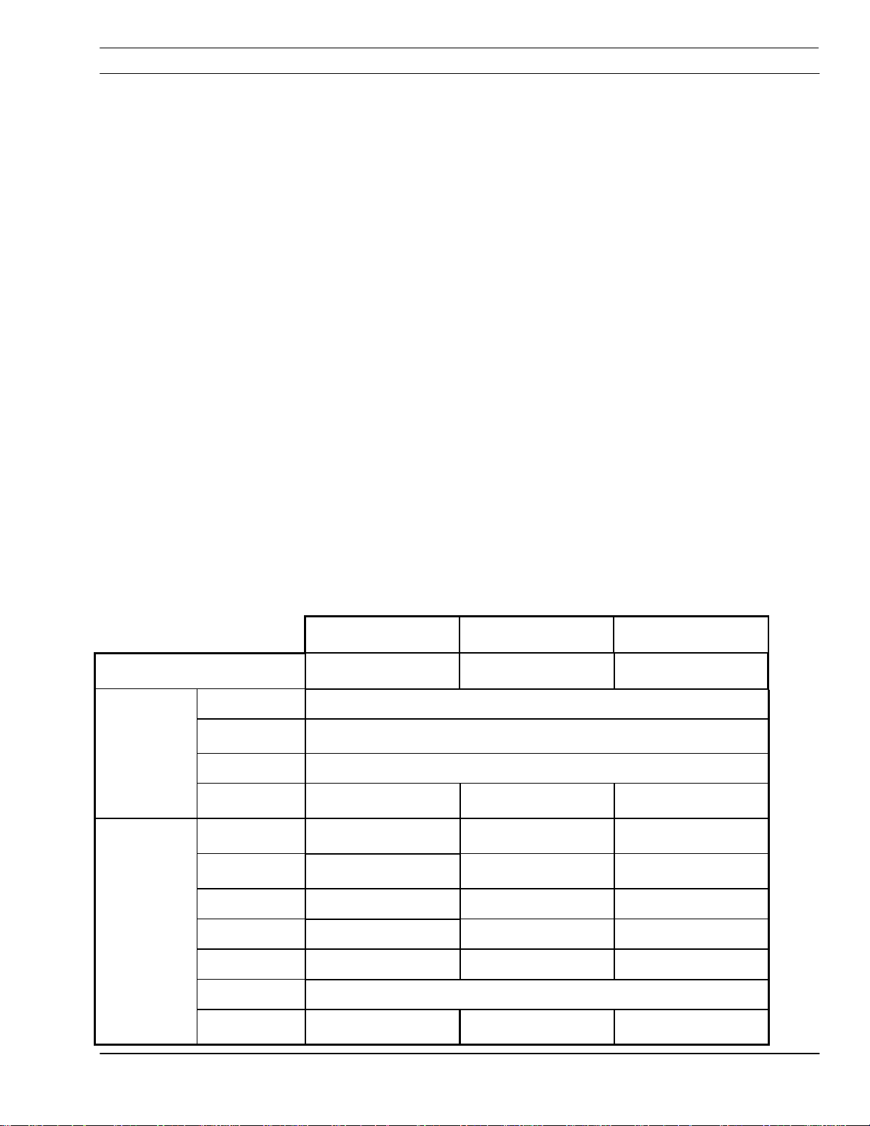
4.2 Control Panel
Covers Removed.
High voltage components are exposed
increasing shock hazard.
Internal component may be damaged
because cooling fans will lose efficiency.
Main Power
Main Power
Main PowerMain Power
Indicator illuminates when input power is applied to
the power source.
Over Temp
Over Temp
Over TempOver Temp
Indicator illuminates when power source has
overheated.
Contactor On
Contactor On
Contactor OnContactor On
Indicator illuminates when the main contactor is
energized.
ESP 400C Plasma Power Source
ESP 400C Plasma Power Source
ESP 400C Plasma Power SourceESP 400C Plasma Power Source
4-1
SECTION 4 Operation
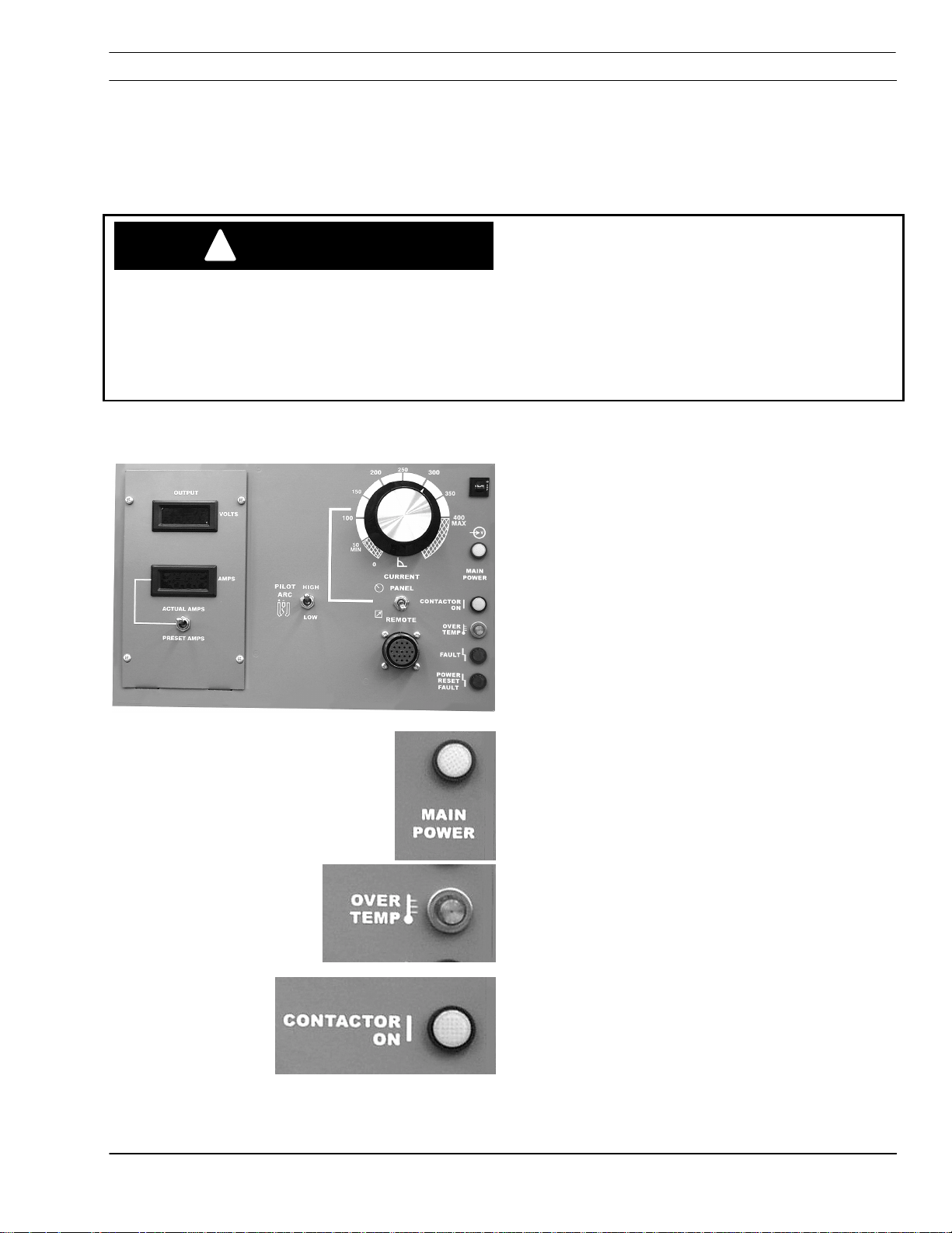
Fault
Fault
FaultFault
Indicator illuminates when there are abnormalities in
the cutting process or when the input line voltage
falls outside of the required nominal value by ±10%.
Power Reset Fault
Power Reset Fault
Power Reset FaultPower Reset Fault
Indicator illuminates when a serious fault is
detected. Input power must be disconnected for at
least 5 seconds and then reapplied.
Current Dial (Potentiometer)
Current Dial (Potentiometer)
Current Dial (Potentiometer)Current Dial (Potentiometer)
ESP-400C dial shown. ESP-400C has a range of
50 to 600 A. Used only in panel mode.
Panel Remote Switch
Panel Remote Switch
Panel Remote SwitchPanel Remote Switch
Controls the location of current control.
Place in the PANEL position for control using
the current potentiometer.
Place in REMOTE position for control from an
external signal (CNC).
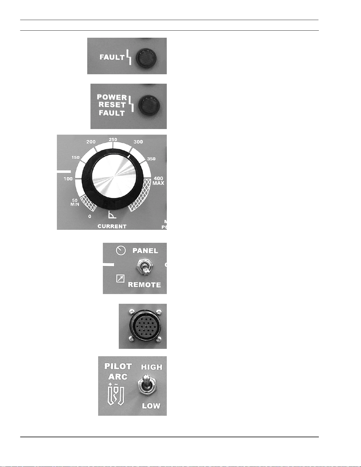
Remote Connection
Remote Connection
Remote ConnectionRemote Connection
Amphenol 19 pin plug for connecting power source
to CNC.
Pilot Arc HIGH/LOW Switch
Pilot Arc HIGH/LOW Switch
Pilot Arc HIGH/LOW SwitchPilot Arc HIGH/LOW Switch
Used to select amount of pilot arc current desired.
As a general rule, for 100 amperes and below, a
setting of LOW is used. This can vary depending
on gas, material and torch used. High/Low settings
are specified in cutting data included in the torch
manual.
4-2
ESP 400C Plasma Power Source
ESP 400C Plasma Power Source
ESP 400C Plasma Power SourceESP 400C Plasma Power Source
 Loading...