

Page 1
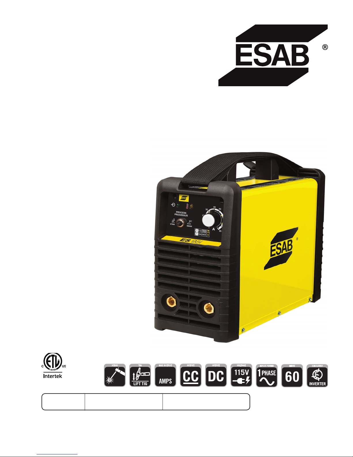
A-13026
95
ESAB ES 95i
Inverter Arc Welder
Operating
Manual
3163339
Révision : AA Issue Date: June 8, 2016 Manual No.: 0-5458
esab.com
Page 2

WE APPRECIATE YOUR BUSINESS!
Congratulations on your new ESAB product. We are proud to have you as our customer and will strive to
provide you with the best service and reliability in the industry. This product is backed by our extensive
warranty and world-wide service network. To locate your nearest distributor or service agency, visit us on
the web at www.esab.com.
This Operating Manual has been designed to instruct you on the correct use and operation of your ESAB
product. Your satisfaction with this product and its safe operation is our ultimate concern. Therefore please
take the time to read the entire manual, especially the Safety Precautions. They will help you to avoid potential
hazards that may exist when working with this product.
YOU ARE IN GOOD COMPANY!
The Brand of Choice for Contractors and Fabricators Worldwide.
ESAB is a Global Brand of manual and automation Plasma Cutting Products.
We distinguish ourselves from our competition through market-leading, dependable products that have stood
the test of time. We pride ourselves on technical innovation, competitive prices, excellent delivery, superior
customer service and technical support, together with excellence in sales and marketing expertise.
Above all, we are committed to developing technologically advanced products to achieve a safer working
environment within the welding industry.
Page 3
WARNING
!
Plasma Cutting Power Supply
ESAB ES95i with Stick Kit
ESAB ES95i with Stick/TIG Kit
Operating Manual Number 0-5458
Published by:
ESAB
2800 Airport Rd.
Denton, TX 76208
www.esab.com
Read and understand this entire Manual and your employer’s safety practices before installing, operating, or servicing the equipment.
While the information contained in this Manual represents the Manufacturer's best judgement,
the Manufacturer assumes no liability for its use.
Copyright 2015 by ESAB
All rights reserved.
Reproduction of this work, in whole or in part, without written permission of the
publisher is prohibited.
The publisher does not assume and hereby disclaims any liability to any party for
any loss or damage caused by any error or omission in this Manual, whether such
error results from negligence, accident, or any other cause.
For Printing Material Specification refer to document: 47x1909
Original Publication Date: June 8, 2016
Revision Date:
Record the following information for Warranty purposes:
Where Purchased:_______________________________ __________
Purchase Date:__________________________________ __________
Power Supply Serial #:___________________________ __________
Torch Serial #:___________________________________ __________
i
Page 4
Be sure this information reaches the operator.
You can get extra copies through your supplier.
CAUTION
These INSTRUCTIONS are for experienced operators. If you are not fully familiar
with the principles of operation and safe practices for arc welding and cutting equipment, we urge you to read our booklet, “Precautions and Safe Practices for Arc
Welding, Cutting, and Gouging,” Form 52-529. Do NOT permit untrained persons to
install, operate, or maintain this equipment. Do NOT attempt to install or operate this
equipment until you have read and fully understand these instructions. If you do not
fully understand these instructions, contact your supplier for further information. Be
sure to read the Safety Precautions before installing or operating this equipment.
USER RESPONSIBILITY
This equipment will perform in conformity with the description thereof contained in this manual and accompanying labels and/or inserts when installed, operated, maintained and repaired in accordance with the instructions
provided. This equipment must be checked periodically. Malfunctioning or poorly maintained equipment should not be
used. Parts that are broken, missing, worn, distorted or contaminated should be replaced immediately. Should such repair or replacement become necessary, the manufacturer recommends that a telephone or written request for service
advice be made to the Authorized Distributor from whom it was purchased.
This equipment or any of its parts should not be altered without the prior written approval of the manufacturer.
The user of this equipment shall have the sole responsibility for any malfunction which results from improper use,
faulty maintenance, damage, improper repair or alteration by anyone other than the manufacturer or a service facility
designated by the manufacturer.
READ AND UNDERSTAND THE INSTRUCTION MANUAL BEFORE INSTALLING OR
PROTECT YOURSELF AND OTHERS!
!
OPERATING.
Page 5

EU DECLARATION OF CONFORMITY
According to
The Low Voltage Directive 2014/35/EU, entering into force 20 April 2016
The EMC Directive 2014/30/EU, entering into force 20 April 2016
The RoHS Directive 2011/65/EU, entering into force 2 January 2013
Type of equipment
WELDING POWER SUPPLY
Type designation etc.
ESAB ES 95i
Brand name or trade mark
ESAB
Manufacturer or his authorised representative established within the EEA
Name, address, telephone No:
ESAB Group Inc.
2800 Airport Rd
Denton TX 76207
Phone: +01 800 426 1888, FAX +01 603 298 7402
The following harmonised standard in force within the EEA has been used in the design:
EN 60974-1:2012 Arc Welding Equipment - Part 1: Welding power sources.
EN 60974-10:2007 Arc Welding Equipment - Part 10: Electromagnetic compatibility (EMC) requirements
Additional Information: Restrictive use, Class A equipment, intended for use in location other than residential.
By signing this document, the undersigned declares as manufacturer, or the manufacturer’s authorised
representative established within the EEA, that the equipment in question complies with the safety requirements stated above.
Date Signature Position
1 November 2015 Vice President,
Antonio Leon Brand Management
Manual Cutting Equipment
2016
Page 6

Page 7

TABLE OF CONTENTS
SECTION 1: SAFETY ........................................................................................ 1-1
1.01 Safety Precautions .......................................................................................... 1-1
SECTION 2:
INTRODUCTION ...................................................................................... 2-1
2.01 How To Use This Manual ................................................................................ 2-1
2.02 Equipment Identification ................................................................................. 2-1
2.03 Receipt Of Equipment ..................................................................................... 2-1
2.04 Description ..................................................................................................... 2-1
2.05 Transportation Methods .................................................................................. 2-2
2.06 Duty Cycle ....................................................................................................... 2-2
SECTION 3:
INSTALLATION ....................................................................................... 3-1
3.01 Environment ................................................................................................... 3-1
3.02 Location .......................................................................................................... 3-1
3.03 Electrical Input Connections ........................................................................... 3-1
3.04 Electromagnetic Compatibility ........................................................................ 3-4
3.05 Setup for Welding ........................................................................................... 3-5
3.06 SMAW (Stick) Setup ....................................................................................... 3-6
3.07 GTAW (Lift TIG) Setup .................................................................................... 3-7
SECTION 4:
OPERATION ........................................................................................... 4-1
4.01 Front Panel ..................................................................................................... 4-1
4.02 SMAW Electrode Polarity ................................................................................ 4-2
4.03 Effects of SMAW (Stick) Welding Various Materials ....................................... 4-2
4.04 GTAW (Lift TIG) Electrode Polarity .................................................................. 4-3
4.05 Guide for Selecting Filler Wire ........................................................................ 4-3
4.06 Tungsten Electrode Current Ranges ................................................................ 4-3
4.07 Shielding Gas Selection .................................................................................. 4-3
4.08 Tungsten Electrode Types ............................................................................... 4-3
4.09 GTAW (Lift TIG) Welding Parameters for Steel ............................................... 4-3
4.10 Arc Welding Practice ....................................................................................... 4-4
4.11 Welding Position ............................................................................................. 4-4
4.12 Joint Preparations ........................................................................................... 4-5
4.13 Arc Welding Technique ................................................................................... 4-6
4.14 The Welder ...................................................................................................... 4-6
4.15 Striking the Arc ............................................................................................... 4-6
4.16 Arc Length ...................................................................................................... 4-6
4.17 Rate of Travel .................................................................................................. 4-6
4.18 Making Welded Joints ..................................................................................... 4-6
4.19 Distortion ........................................................................................................ 4-8
4.20 The Cause of Distortion .................................................................................. 4-8
4.21 Overcoming Distortion Effects ........................................................................ 4-9
Page 8

TABLE OF CONTENTS
SECTION 5:
SERVICE ............................................................................................... 5-1
5.01 Maintenance and Inspection ........................................................................... 5-1
5.02 SMAW (Stick) Welding Problems .................................................................. 5-2
5.03 GTAW (Lift TIG) Welding Problems ............................................................... 5-3
5.04 Power Source Problems ................................................................................ 5-4
APPENDIX 1: REPLACEMENT PARTS .................................................................... A-1
APPENDIX 2: OPTIONS AND ACCESSORIES ............................................................ A-2
APPENDIX 3: system schematic ......................................................................... A-3
INTERNATIONAL CONTACT INFORMATION ................................................. REAR COVER
Page 9
ESAB ES 95i
SECTION 1: SAFETY
1.01 Safety Precautions
Users of ESAB welding and plasma cutting equipment have the ultimate responsibility for ensuring that anyone who works
on or near the equipment observes all the relevant safety precautions. Safety precautions must meet the requirements that
apply to this type of welding or plasma cutting equipment. The following recommendations should be observed in addition to
the standard regulations that apply to the workplace.
All work must be carried out by trained personnel well acquainted with the operation of the welding or plasma cutting
equipment. Incorrect operation of the equipment may lead to hazardous situations which can result in injury to the operator
and damage to the equipment.
1. Anyone who uses welding or plasma cutting equipment must be familiar with:
- its operation
- location of emergency stops
- its function
- relevant safety precautions
- welding and / or plasma cutting
2. The operator must ensure that:
- no unauthorized person stationed within the working area of the equipment when it is started up.
- no one is unprotected when the arc is struck.
3. The workplace must:
- be suitable for the purpose
- be free from drafts
4. Personal safety equipment:
- Always wear recommended personal safety equipment, such as safety glasses, flame proof
clothing, safety gloves.
- Do not wear loose fitting items, such as scarves, bracelets, rings, etc., which could become
trapped or cause burns.
5. General precautions:
- Make sure the return cable is connected securely.
- Work on high voltage equipment may only be carried out by a qualified electrician.
- Appropriate fire extinguishing equipment must be clearly marked and close at hand.
- Lubrication and maintenance must not be carried out on the equipment during operation.
Dispose of electronic equipment at the recycling facility!
In observance of European Directive 2002/96/EC on Waste Electrical and Electronic Equipment and its
implementation in accordance with national law, electrical and/or electronic equipment that has reached
the end of its life must be disposed of at a recycling facility.
As the person responsible for the equipment, it is your responsibility to obtain information on approved
collection stations.
For further information contact the nearest ESAB dealer.
ESAB can provide you with all necessary cutting protection and accessories.
Manual 0-5458 1-1 SAFETY INSTRUCTIONS AND WARNINGS
Page 10
ESAB ES 95i
WARNING
ELECTRIC SHOCK - Can kill.
- Install and earth (ground) the welding or plasma cutting unit in accordance with applicable standards.
- Do not touch live electrical parts or electrodes with bare skin, wet gloves or wet clothing.
- Insulate yourself from earth and the workpiece.
- Ensure your working stance is safe.
FUMES AND GASES - Can be dangerous to health.
- Keep your head out of the fumes.
- Use ventilation, extraction at the arc, or both, to take fumes and gases away from your
breathing zone and the general area.
ARC R AYS - Can injure eyes and burn skin.
- Protect your eyes and body. Use the correct welding / plasma cutting screen and filter
lens and wear protective clothing.
- Protect bystanders with suitable screens or curtains.
FIRE HAZARD
- Sparks (spatter) can cause fire. Make sure therefore that there are no inflammable materials nearby.
Arc welding and cutting can be injurious to yourself and others. Take
precautions when welding and cutting. Ask for your employer's safety
practices which should be based on manufacturers' hazard data.
NOISE - Excessive noise can damage hearing.
- Protect your ears. Use earmuffs or other hearing protection.
- Warn bystanders of the risk.
MALFUNCTION - Call for expert assistance in the event of malfunction.
READ AND UNDERSTAND THE INSTRUCTION MANUAL BEFORE INSTALLING OR OPERATING.
PROTECT YOURSELF AND OTHERS!
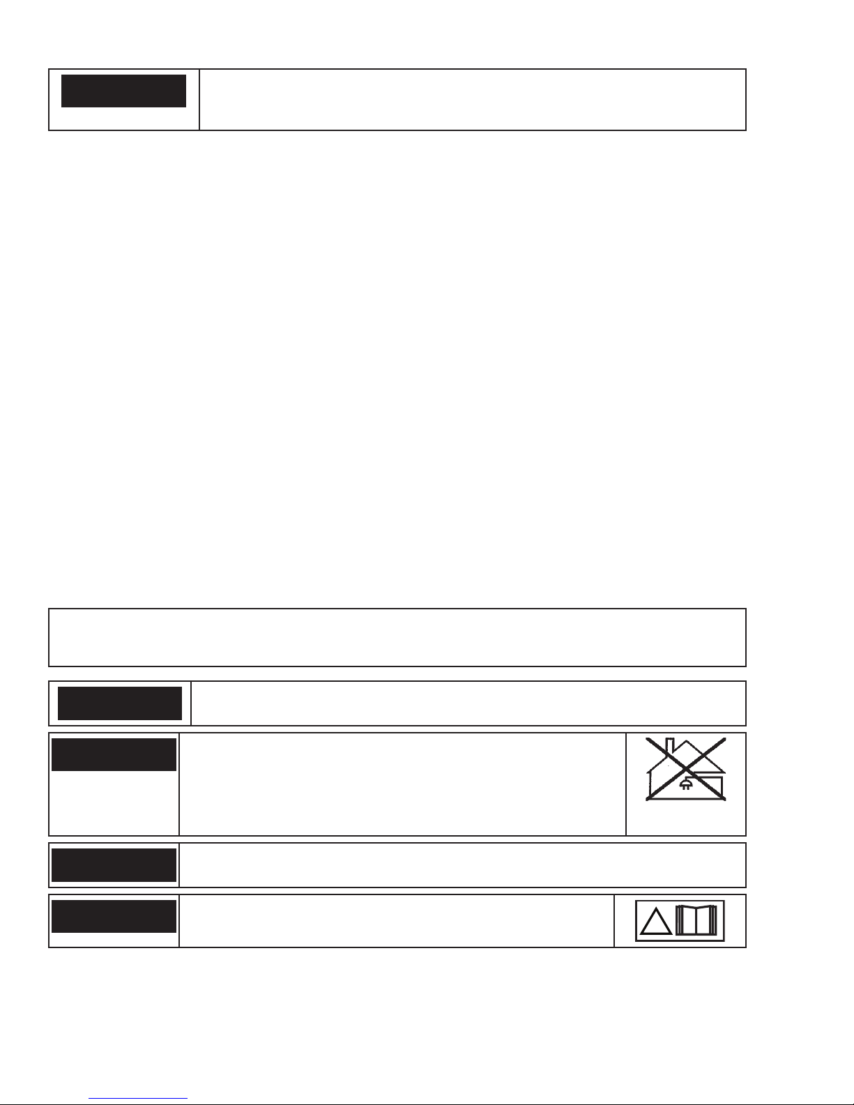
Do not use the power source for thawing frozen pipes.
WARNING
CAUTION
CAUTION
CAUTION
Class A equipment is not intended for use in residential locations
where the electrical power is provided by the public low-voltage
supply system. There may be potential difficulties in ensuring
electromagnetic compatibility of class A equipment in those locations, due to conducted as well as radiated disturbances.
This product is solely intended for metal removal. Any other use may
result in personal injury and / or equipment damage.
Read and understand the instruction manual before
installing or operating.
!
SAFETY INSTRUCTIONS AND WARNINGS 1-2 Manual 0-5458
Page 11
SECTION 2:
!
INTRODUCTION
ESAB ES 95i
2.01 How To Use This Manual
This Owner’s Manual applies to just specification or part numbers
listed on page i.
To ensure safe operation, read the entire manual, including the
chapter on safety instructions and warnings.
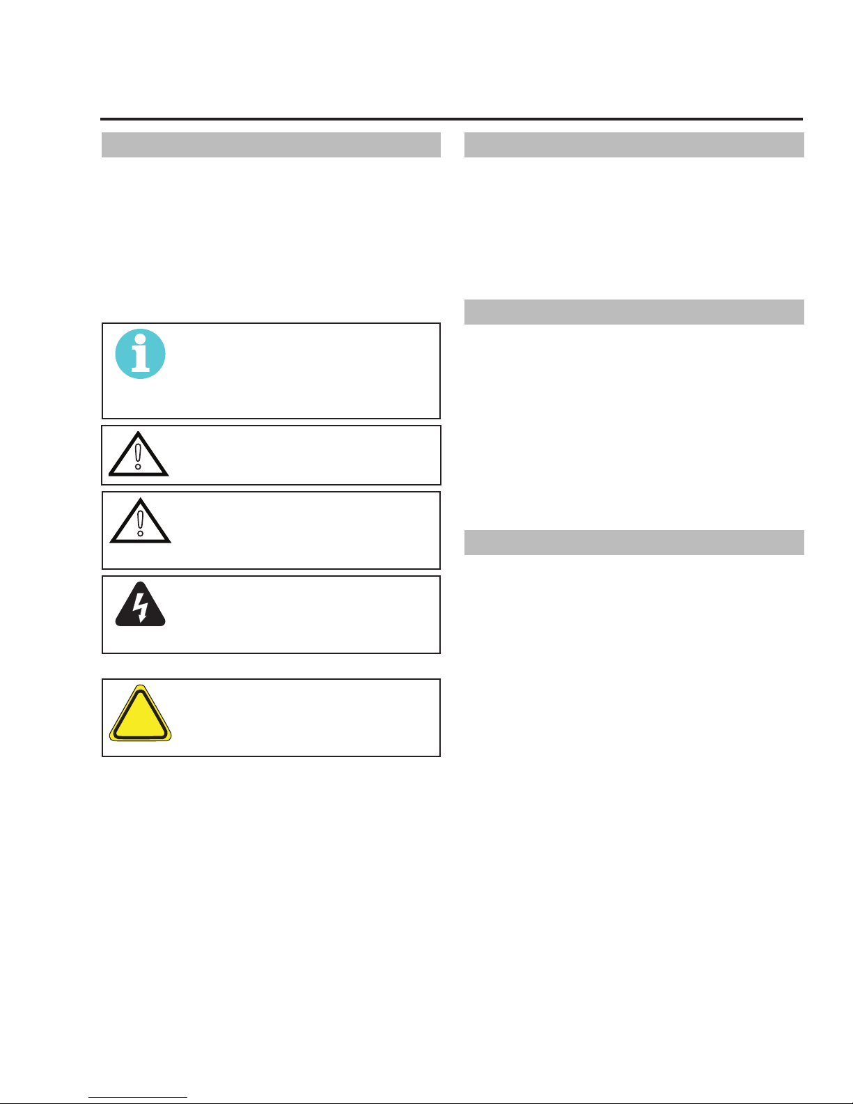
Throughout this manual, the words WARNING, CAUTION, DANGER,
and NOTE may appear. Pay particular attention to the information
provided under these headings. These special annotations are
easily recognized as follows:
NOTE!
An operation, procedure, or background
information which requires additional emphasis or is helpful in efficient operation of
the system.
CAUTION
!
!
A procedure which, if not properly followed,
may cause damage to the equipment.
WARNING
A procedure which, if not properly followed,
may cause injury to the operator or others
in the operating area.
WARNING
Gives information regarding possible electrical shock injury. Warnings will be enclosed
in a box such as this.
DANGER
Means immediate hazards which, if not
avoided, will result in immediate, serious
personal injury or loss of life.
2.02 Equipment Identification
The unit’s identification number (specification or part number),
model, and serial number usually appear on a data tag attached
to the rear panel. Equipment which does not have a data tag
such as torch and cable assemblies are identified only by the
specification or part number printed on loosely attached card or
the shipping container. Record these numbers on the bottom of
page i for future reference.
2.03 Receipt Of Equipment
When you receive the equipment, check it against the invoice to
make sure it is complete and inspect the equipment for possible
damage due to shipping. If there is any damage, notify the carrier
immediately to file a claim. Furnish complete information concerning damage claims or shipping errors to the location in your
area listed in the inside back cover of this manual.
Include all equipment identification numbers as described above
along with a full description of the parts in error.
Move the equipment to the installation site before un-crating the
unit. Use care to avoid damaging the equipment when using bars,
hammers, etc., to un-crate the unit.
2.04 Description
This compact inverter welding machine has infinitely adjustable
welding current from 5 to 95 amps. It uses standard general
purpose SMAW 3/32” (2.5mm) electrodes for light gauge work,
generally less than 1/8” (3.2mm) thick. The unit also has a
GTAW (Lift TIG) welding mode that offers stable TIG welding
characteristics when used with a suitable TIG torch and shielding
gas.
Additional copies of this manual may be purchased by contacting
ESAB at the address and phone number in your area listed on
back cover of this manual. Include the Owner’s Manual number
and equipment identification numbers.
Electronic copies of this manual can also be downloaded at no
charge in Acrobat PDF format by going to the ESAB web site
listed below
http://www.esab.com
Manual 0-5458 2-1 INTRODUCTION
Page 12
ESAB ES 95i
!
2.05 Transportation Methods
CAUTION
!
Lift unit with handle on top of case. Use handcart or similar device of adequate capacity. If using a fork lift vehicle, place secure unit on
a proper skid before transporting.
2.06 Duty Cycle
The rated duty cycle of a Welding Power Source, is a statement of the time it may be operated at its rated welding current output
without exceeding the temperature limits of the insulation of the component parts. To explain the 10 minute duty cycle period the
following example is used. Suppose a Welding Power Source is designed to operate at a 40% duty cycle, 75 amperes at 23 volts. This
means that it has been designed and built to provide the rated amperage (75A) for 4 minutes, i.e. arc welding time, out of every 10
minute period (40% of 10 minutes is 4 minutes). During the other 6 minutes of the 10 minute period the Welding Power Source must
idle and allowed to cool.
ELECTRIC SHOCK can kill. DO NOT TOUCH live electric parts. Disconnect input power conductors from deenergized supply line before moving the welding power source.
WARNING
FALLING EQUIPMENT can cause serious personal injury and equipment damage.
INTRODUCTION 2-2 Manual 0-5458
Page 13
!
SECTION 3:
!
INSTALLATION
ESAB ES 95i
3.01 Environment
These units are designed for use in environments with increased
hazard of electric shock. Examples of environments with
increased hazard of electric shock are:
A. In locations in which freedom of movement is restricted, so
that the operator is forced to perform the work in a cramped
(kneeling, sitting or lying) position with physical contact
with conductive parts.
B. In locations which are fully or partially limited by conductive
elements, and in which there is a high risk of unavoidable
or accidental contact by the operator.
C. In wet or damp hot locations where humidity or perspiration
considerably reduces the skin resistance of the human body
and the insulation properties of accessories.
Environments with increased hazard of electric shock do not
include places where electrically conductive parts in the near
vicinity of the operator, which can cause increased hazard, have
been insulated.
3.02 Location
Be sure to locate the welder according to the following guidelines:
• In areas, free from moisture and dust.
• Ambient temperature between 32°F (0°C) to 104° F (40°
C).
• In areas, free from oil, steam and corrosive gases.
• In areas, not subjected to abnormal vibration or shock.
• In areas, not exposed to direct sunlight or rain.
• Place at a distance of 12” (300mm) or more from walls or
similar that could restrict natural air flow for cooling
3.03 Electrical Input Connections
WARNING
ELECTRIC SHOCK can kill; SIGNIFICANT DC
VOLTAGE is present after removal of input
power.
DO NOT TOUCH live electrical parts.
SHUT DOWN welding power source, disconnect input power em-
ploying lockout/tagging procedures. Lock-out/tagging procedures
consist of padlocking line disconnect switch in open position,
removing fuses from fuse box, or shutting off and red-tagging
circuit breaker or other disconnecting device.
Electrical Input Requirements
Operate the welding power source from a single-phase 60 Hz, AC
power supply. The input voltage must match one of the electrical input voltages shown on the input data label on the unit
nameplate. Contact the local electric utility for information about
the type of electrical service available, how proper connections
should be made, and inspection required. The line disconnect
switch provides a safe and convenient means to completely
remove all electrical power from the welding power supply
whenever necessary to inspect or service the unit.
Do not connect an input (WHITE or BLACK) conductor to the
ground terminal.
Do not connect the ground (GREEN) conductor to an input line
terminal.
WARNING
ESAB advises that this equipment be electrically connected by a qualified electrician.
Manual 0-5458 3-1 INSTALLATION
Page 14
ESAB ES 95i
Art #: A-08473_AB
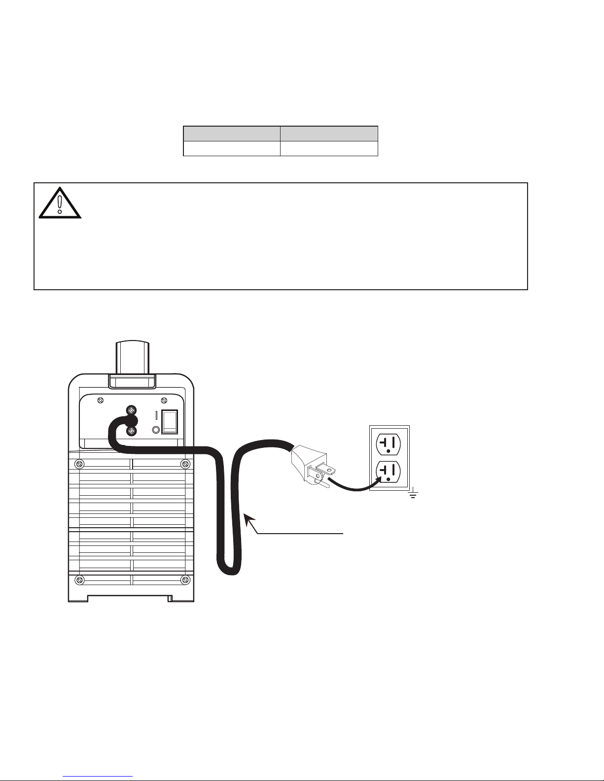
Refer to Figure 3-1:
1. Connect end of ground (GREEN or GREEN/YELLOW) conductor to a suitable ground. Use a grounding method that complies
with all applicable electrical codes.
2. Connect ends of line 1 (BLACK) and line 2 (WHITE) input conductors to a de-energized line disconnect switch.
3. Use Table 3-1 as a guide to select line fuses for the disconnect switch.
Input Voltage Fuse Size
115V 20 Amps
Table 3-1: Fuse Guide
CAUTION
!
The time-delay fuses or circuit breaker of an individual branch circuit may have nuisance tripping when
welding with this product due to the amperage rating of the time-delay fuses or circuit breaker.
The recommended time-delay fuses or circuit breaker size is 20 amperes. Fuse/circuit breaker size is
based on not more than 200 percent of the rated input amperage of the welding power source (Based on
Article 630, National Electrical Code).
An individual branch circuit capable of carrying 20 amperes and time-delay fuses or circuit breaker protection is recommended for this application.
Welding Power Supply
Figure 3-1: Electrical Input Connections
120 V, 20A, 1Ø
Primary Power Cable
INSTALLATION 3-2 Manual 0-5458
Page 15
ESAB ES 95i
Input Power
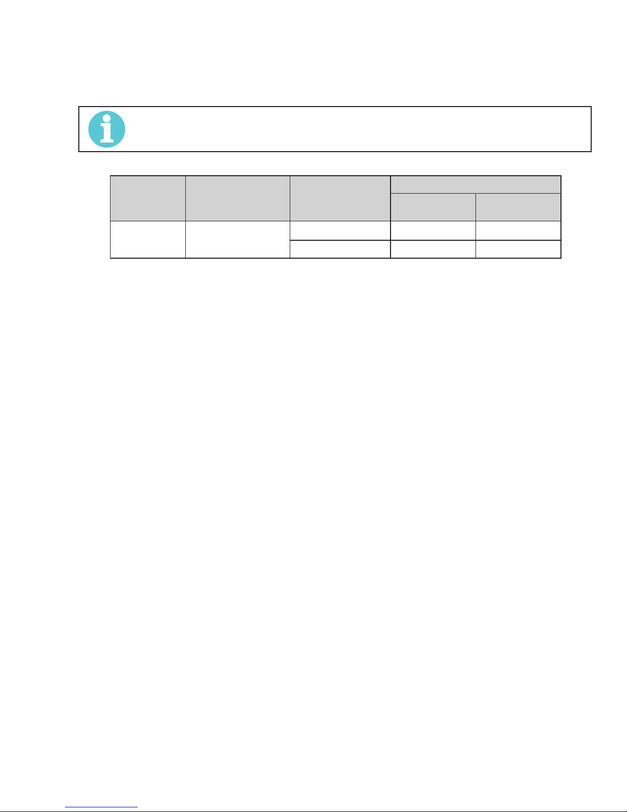
Each unit incorporates an INRUSH circuit. When the MAIN CIRCUIT SWITCH is turned on, the inrush circuit provides pre-charging for the
input capacitors. A relay in the Power Control Assembly (PCA) will turn on after the input capacitors have charged to operating voltage
(after approximately 5 seconds)
NOTE!
Damage to the PCA could occur if 133 VAC or higher is applied to the Primary Power Cable.
Primary Supply Lead Size
Model
ESAB ES95i 12 AWG (3.3mm²)
(Factory Fitted)
Table 3-2: Primary Circuit Sizes to Achieve Maximum Current
Minimum Primary
Current Circuit Size
(Vin/Amps)
115V/20A - 75A / 23V @ 40%
115V/21A 95A / 13.8V @ 20% -
GTAW (Lift TIG) SMAW (Stick)
Current & Duty Cycle
Manual 0-5458 3-3 INSTALLATION
Page 16
ESAB ES 95i
3.04 Electromagnetic Compatibility
WARNING
!
A. Installation and Use - Users Responsibility
The user is responsible for installing and using the welding equipment according to the manufacturer’s instructions. If electromagnetic
disturbances are detected then it shall be the responsibility of the user of the welding equipment to resolve the situation with the
technical assistance of the manufacturer. In some cases this remedial action may be as simple as earthing the welding circuit, see
NOTE below. In other cases it could involve constructing an electromagnetic screen enclosing the Welding Power Source and the work,
complete with associated input filters. In all cases, electromagnetic disturbances shall be reduced to the point where they are no longer
Trouble-some.
B. Assessment of Area
Before installing welding equipment, the user shall make an assessment of potential electromagnetic problems in the surrounding area.
The following shall be taken into account.
1. Other supply cables, control cables, signaling and telephone cables; above, below and adjacent to the welding equipment.
2. Radio and television transmitters and receivers.
3. Computer and other control equipment.
4. Safety critical equipment, e.g. guarding of industrial equipment.
Extra precautions for Electromagnetic Compatibility may be required when this Welding Power Source is
used in a domestic situation.
5. The health of people around, e.g. the use of pace-makers and hearing aids.
6. Equipment used for calibration and measurement.
7. The time of day that welding or other activities are to be carried out.
8. The immunity of other equipment in the environment: the user shall ensure that other equipment being used in the environment
is compatible: this may require additional protection measures.
The size of the surrounding area to be considered will depend on the structure of the building and other activities that are taking place.
The surrounding area may extend beyond the boundaries of the premises.
C. Methods of Reducing Electromagnetic
Emissions
1. Mains Supply
Welding equipment should be connected to the mains supply according to the manufacturer’s recommendations. If interference
occurs, it may be necessary to take additional precautions such as filtering of the mains supply. Consideration should be given
to shielding the supply cable of permanently installed welding equipment in metallic conduit or equivalent. Shielding should
be electrically continuous throughout its length. The shielding should be connected to the Welding Power Source so that good
electrical contact is maintained between the conduit and the Welding Power Source enclosure.
2. Maintenance of Welding Equipment
The welding equipment should be routinely maintained according to the manufacturer’s recommendations. All access and
service doors and covers should be closed and properly fastened when the welding equipment is in operation. The welding
equipment should not be modified in any way except for those changes and adjustments covered in the manufacturer’s
instructions. In particular, the spark gaps of arc striking and stabilizing devices should be adjusted and maintained according
to the manufacturer’s recommendation
3. Welding Cables
The welding cables should be kept as short as possible and should be positioned close together, running at or close to the
floor level.
INSTALLATION 3-4 Manual 0-5458
Page 17
ESAB ES 95i
!
4. Equipotential Bonding
Bonding of all metallic components in the welding installation and adjacent to it should be considered. However, metallic
components bonded to the work piece will increase the risk that the operator could receive a shock by touching the metallic
components and the electrode at the same time. The operator should be insulated from all such bonded metallic components.
5. Earthing of the Work Piece
Where the work piece is not bonded to earth for electrical safety, nor connected to earth because of its size and position, e.g.
ship’s hull or building steelwork, a connection bonding the work piece to earth may reduce emissions in some, but not all
instances. Care should be taken to prevent the earthing of the work piece increasing the risk of injury to users, or damage to
other electrical equipment. Where necessary, the connection of the work piece to earth should be made by direct connection
to the work piece, but in some countries where direct connection is not permitted, the bonding should be achieved by suitable
capacitance, selected according to national regulations.
6. Screening and Shielding
Selective screening and shielding of other cables and equipment in the surrounding area may alleviate problems of interference.
Screening the entire welding installation may be considered for special applications.
3.05 Setup for Welding
NOTE!
Conventional operating procedures apply when using the Welding Power Source, i.e. connect work lead
directly to work piece and electrode lead is used to hold electrode. Wide safety margins provided by the design ensure that the Welding Power Source will withstand short-term overload without adverse effects. The
welding current range values should be used as a guide only. Current delivered to the arc is dependent on
the welding arc voltage, and as welding arc voltage varies between different classes of electrodes, welding
current at any one setting would vary according to the type of electrode in use. The operator should use the
welding current range values as a guide then fine tune the welding current to suit the application.
WARNING
Before connecting the work clamp to the work and inserting the electrode in the electrode holder make
sure the Primary power supply is switched off.
CAUTION
!
Remove any packaging material prior to use. Do not block the air vents at the front or rear of the Welding
Power Source.
Manual 0-5458 3-5 INSTALLATION
Page 18
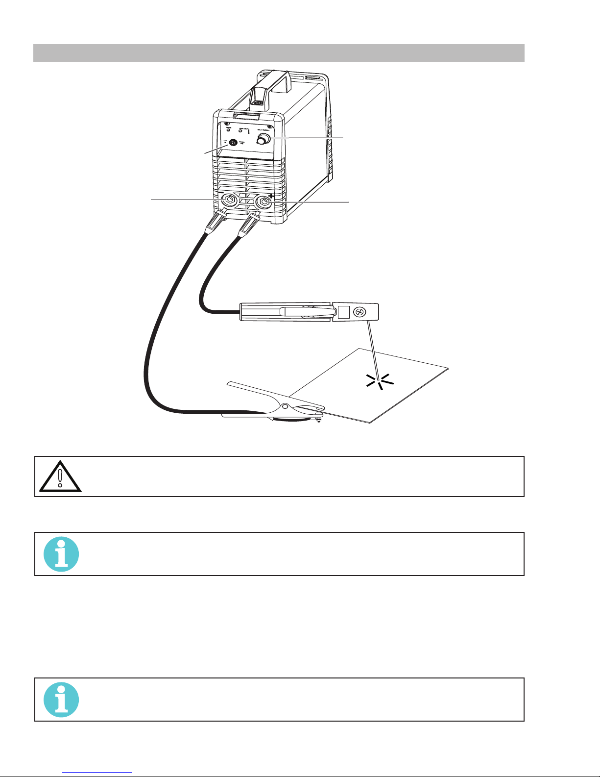
ESAB ES 95i
200A
Set Welding Current
as specified by the
Electrode Manufacturer.
Set Process Selection
Switch to SMAW (Stick)
Positive Output
Terminal
(Dinse™ 25)
Negative Output
Terminal
(Dinse™ 25)
Art #: A-08602_AC
3.06 SMAW (Stick) Setup
Figure 3-2: Setup for SMAW (Stick) Welding
SMAW (Stick) Mode Sequence of Operation
CAUTION
!
1. Switch the ON/OFF Switch (located on the rear panel) to OFF.
2. Connect the ground clamp cable to the negative output terminal, and the electrode holder cable to the positive output terminal.
3. Connect the ground clamp to your workpiece.
4. Plug the power cable into the appropriate outlet, and turn the switch to the “ON” position. The power L.E.D light should
illuminate.
5. Set the “Process Selection Switch” to SMAW (Stick)
6. Set the weld current control knob to the desired amperage.
7. Install a stick electrode in the electrode holder.
8. You are now ready to begin SMAW (Stick) Welding
Before any welding is to begin, be sure to wear all appropriate and recommended safety equipment.
NOTE!
This set up is known as DC Electrode Positive or reverse polarity. Please consult with the stick electrode
manufacturer for specific polarity recommendations.
NOTE!
Gently strike the electrode on the work piece to generate a welding arc, and slowly move along the work
piece while holding a consistent arc length above base metal.
INSTALLATION 3-6 Manual 0-5458
Page 19
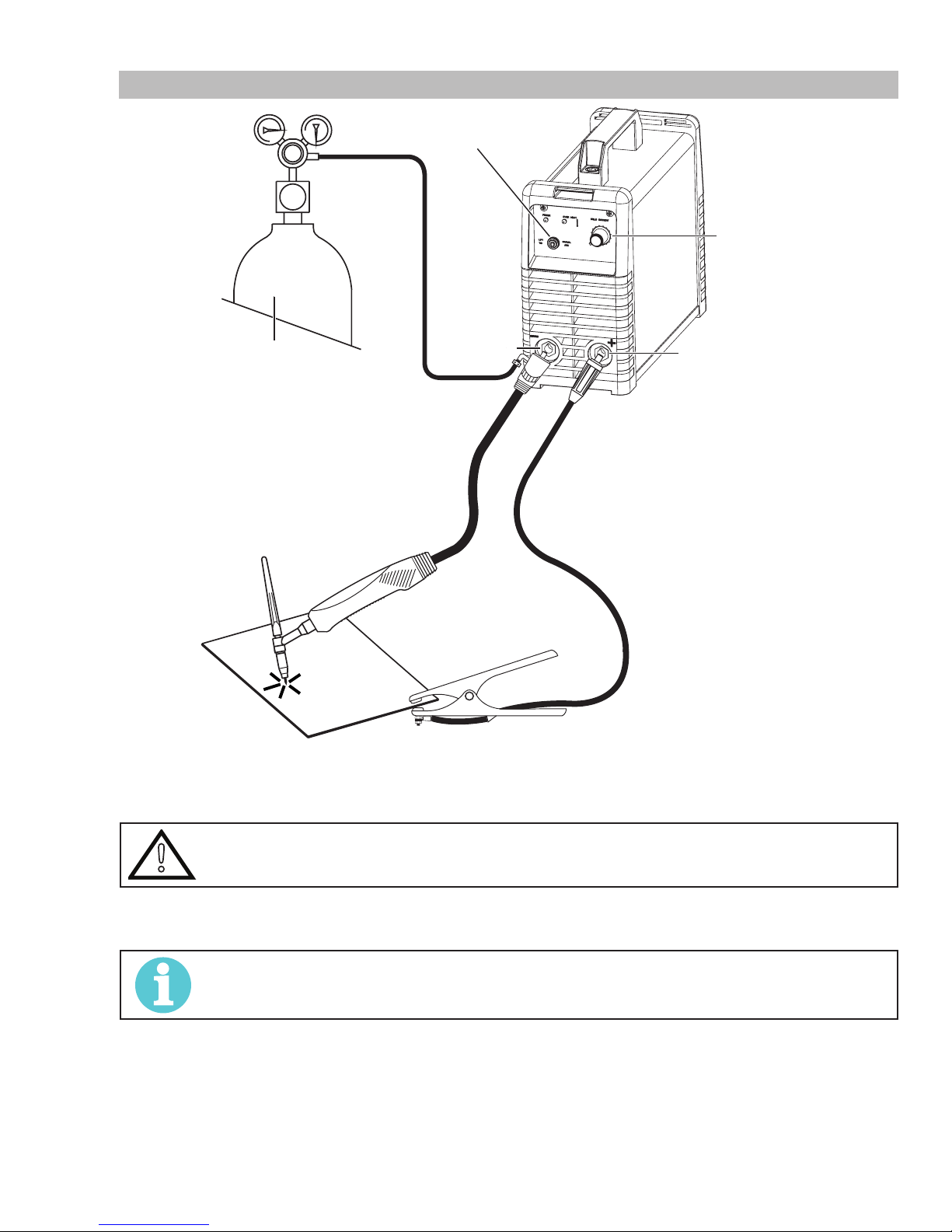
3.07 GTAW (Lift TIG) Setup
Secure the gas cylinder in an
upright position by chaining it
to a stationary support to prevent
falling or tipping.
Set Process Selection
Switch to GTAW (Lift TIG).
Negative
Output
Terminal
(Dinse™ 25)
ESAB ES 95i
Set Welding Current
as specified by the
Electrode Manufacturer.
Positive Output
Terminal
(Dinse™ 25)
Art #: A-08603_AC
Figure 3-3: Setup for GTAW (Lift TIG) Welding
GTAW (Lift TIG) Sequence of Operation
CAUTION
!
1. Switch the ON/OFF Switch (located on the rear panel) to OFF.
2. Connect the ground clamp cable to positive output terminal, and the TIG torch cable to the negative output terminal.
Before any welding is to begin, be sure to wear all appropriate and recommended safety equipment.
NOTE!
This set up is known as Straight Polarity or DC Electrode Negative. This is commonly used for DC TIG welding on most materials such as steel and stainless steel.
3. Using a secured Argon cylinder, slowly crack open then close the cylinder valve while standing off to the side of the valve.
This will remove any debris that may be around the valve & regulator seat area.
4. Install the regulator and tighten with a wrench.
5. Connect the gas hose to the outlet of the Argon regulator, and tighten with a wrench.
6. Be sure the gas valve on the torch is closed, and slowly open the Argon Cylinder Valve to the fully open position.
7. Connect the ground clamp to your work piece.
Manual 0-5458 3-7 INSTALLATION
Page 20
ESAB ES 95i
8. Plug the power cable into the appropriate outlet, and turn the switch to the “ON” position. The power L.E.D. light should
illuminate.
9. Set the “Process Selection Switch” to GTAW (Lift TIG)
10. Set the weld current control knob to the desired amperage.
11. The tungsten must be ground to a blunt point in order to achieve optimum welding results. It is critical to grind the tungsten
electrode in the direction the grinding wheel is turning.
12. Install the tungsten with approximately 1/8” to ¼” sticking out from the gas cup, ensuring you have correct sized collet.
13. Tighten the back cap.
14. You are now ready to begin TIG Welding
NOTE!
Open the gas valve on TIG torch handle, and adjust the pressure of regulator to 15-25 cubic feet per hour.
This gas flow should be sufficient for most TIG welding applications.
ii. Touch the tungsten to the work piece. This closes the welding circuit, and the arc starts by slowly
LIFTING the torch off the base metal. Keep a consistent arc length of about 1/8-1/4”.
iii. If necessary re-adjust the amperage setting to an appropriate level.
.
INSTALLATION 3-8 Manual 0-5458
Page 21
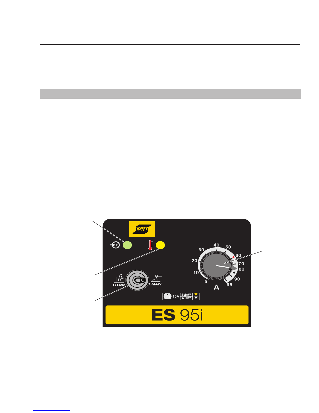
ESAB ES 95i
Art # A-13030
(A) Process
Selection
Switch
(C) Warning
Indicator
(B) Power On
Indicator
(D) Welding
Current
Control
SECTION 4:
OPERATION
Conventional operating procedures apply when using the Welding Power Source, i.e. connect work lead directly to work piece and
electrode lead is used to hold the electrode. The welding current range values should be used as a guide only. Current delivered to the
arc is dependent on the welding arc voltage, and as welding arc voltage varies between different classes of electrode, welding current
at any one setting would vary according to the type of electrode in use. The operator should use the welding current range values as
a guide then fine tune the welding current to suit the specific application. Refer to the electrode manufacture's literature for further
information.
4.01 Front Panel
(A) Process Selection Switch
Switches between GTAW (Lift TIG) and SMAW (Stick) Welding modes.
(B) Power On Indicator
The Power ON Indicator illuminates when the ON/OFF switch is in the ON position and the nominal mains voltage is present.
(C) Over Heat Indicator
The welding power source is protected by a self resetting thermostat. The indicator will illuminate if the duty cycle of the power source
has been exceeded. If the Over Heat light illuminates wait for the Over Heat light to extinguish before resuming welding.
(D) Welding Current Control
The welding current is increased by turning the Weld Current control knob clockwise or decreased by turning the Weld Current control
knob counterclockwise. The welding current should be set according to the specific application. Refer to the electrode manufacture's
literature for further information.
(E) ON/OFF Switch (located on rear panel - not shown)
This switch controls the Mains Supply Voltage to the Power Source.
Manual 0-5458 4-1 OPERATION
Figure 4-1: 95i DC Controls
Page 22
ESAB ES 95i
4.02 SMAW Electrode Polarity
Stick electrodes are generally connected to the "+" Positive Output Terminal and the work lead to the "−" Negative Output Terminal but
if in doubt consult the electrode manufacturers literature for further information.
4.03 Effects of SMAW (Stick) Welding Various Materials
High Tensile and Alloy Steels
The two most prominent effects of welding these steels are the formation of a hardened zone in the weld area, and, if suitable
precautions are not taken, the occurrence in this zone of under-bead cracks. Hardened zone and under-bead cracks in the weld area
may be reduced by using the correct electrodes, preheating, using higher current settings, using larger electrodes sizes, short runs for
larger electrode deposits or tempering in a furnace.
Manganese Steels
The effect on manganese steel of slow cooling from high temperatures is to embrittle it. For this reason it is absolutely essential to keep
manganese steel cool during welding by quenching after each weld or skip welding to distribute the heat.
Cast Iron
Most types of cast iron, except white iron, are weldable. White iron, because of its extreme brittleness, generally cracks when attempts
are made to weld it. Trouble may also be experienced when welding white-heart malleable, due to the porosity caused by gas held in
this type of iron.
Copper and Alloys
The most important factor is the high rate of heat conductivity of copper, making pre-heating of heavy sections necessary to give
proper fusion of weld and base metal.
Types of Electrodes
Arc Welding electrodes are classified into a number of groups depending on their applications. There are a great number of electrodes
used for specialized industrial purposes which are not of particular interest for everyday general work. These include some low
hydrogen types for high tensile steel, cellulose types for welding large diameter pipes, etc The range of electrodes dealt with in this
publication will cover the vast majority of applications likely to be encountered; are all easy to use.
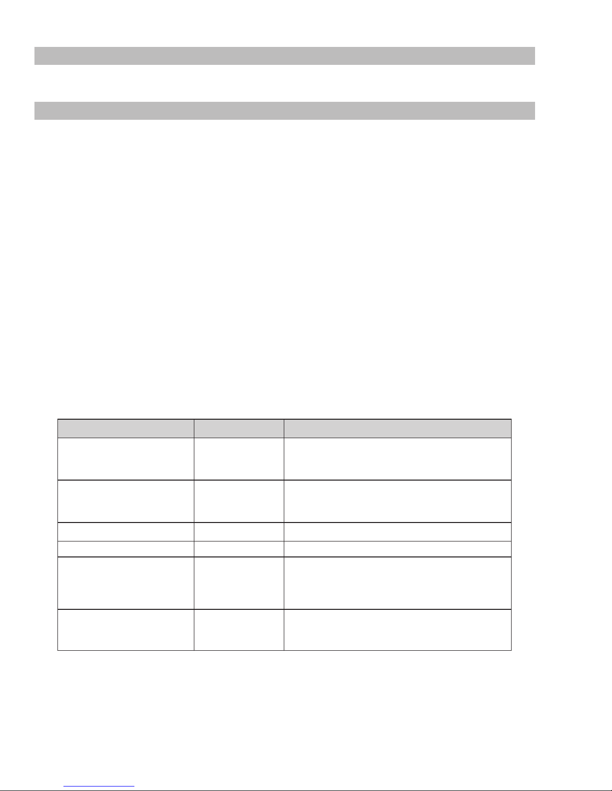
Metal Being Joined Electrode Comments
Ideal electrodes for all general purpose work, features
Mild Steel 6013
Mild Steel 7014
Cast Iron 99% Nickel Suitable for joining all cast irons except white cast iron.
Stainless Steel 318L-16 High corrosion resistances. Ideal for dairy work etc.
Copper, Bronze, Etc.
Copper, Bronze, Dissimilar Metals,
Crack Resistance, All Hard-to Weld
Jobs
Bronze
5.7 ERCUSI-A
312-16
include outstanding operator appeal, easy arc starting, and
All positional eletrode for use on mild and galvanized steel
furniture, plates, fences, gates, piples and tanks, etc. Espe-
cially suitable for vertical-down welding.
Easy to use electrode for marine fittings, water taps and
valves, water through floats arms, etc. Also for joining cop-
per to steel and for bronze overlays on steel shafts.
It will weld most problematic jobs such as springs, shafts,
broken joins, mild steel to stainless and alloy steels. Not
suitable for aluminum.
low spatter.
OPERATION 4-2 Manual 0-5458
Page 23
ESAB ES 95i
4.04 GTAW (Lift TIG) Electrode Polarity
Connect the TIG torch to the "-" Negative Output Terminal and
the work lead to the "+" Positive Output Terminal for direct
current straight polarity. Direct current straight polarity is the
most widely used polarity for DC TIG welding. It allows limited
wear of the electrode since 70% of the heat is concentrated at
the work piece.
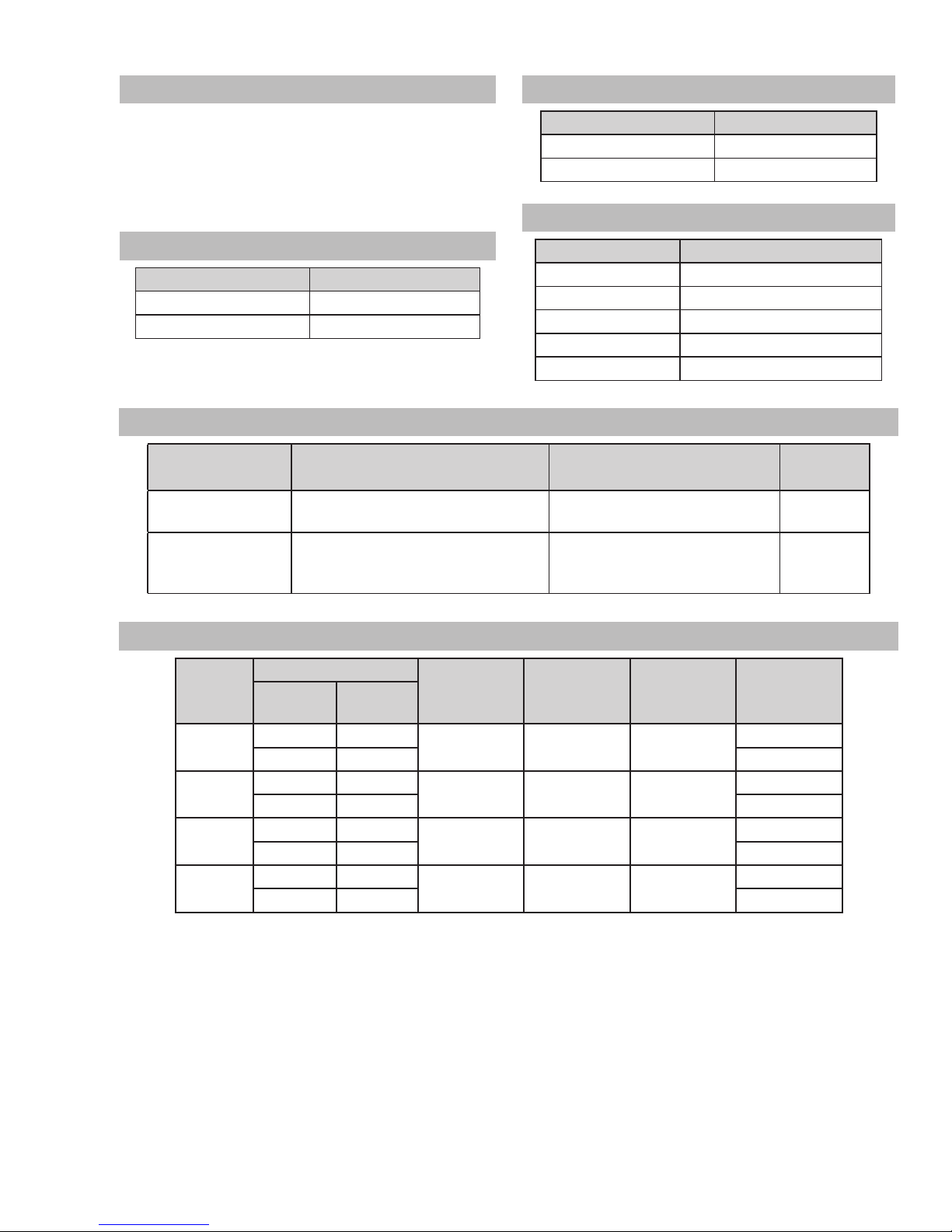
4.05 Guide for Selecting Filler Wire
Filler Wire Diameter DC Current (Amps)
1/16" (1.6mm) 20 - 90
3/32" (2.4mm) 60 - 115
4.08 Tungsten Electrode Types
Electrode Type
(Ground Finish)
Thoriated 2%
Ceriated 2%
DC welding of mild steel, stainless steel and
AC & DC welding of mild steel, stainless
steel, copper, aluminum, magnesium and
Welding Application Features Color Code
copper.
their alloys.
4.06 Tungsten Electrode Current Ranges
Electrode Diameter DC Current
.040" (1.0mm) 20 - 90
1/16" (1.6mm) 60 - 115
4.07 Shielding Gas Selection
Alloy Shielding Gas
Carbon Steel Welding Argon
Stainless Steel Welding Argon
Nickel Alloy Welding Argon
Copper Welding Argon
Titanium Welding Argon
Excellent arc starting, long life, high
current carrying capacity.
Longer life, more stable arc, easier
starting, wider current range, narrower
& more concentrated arc.
Red
Grey
4.09 GTAW (Lift TIG) Welding Parameters for Steel
Base
Metal
Thickness
0.040”
(1.0mm)
0.045”
(1.22mm)
1/16”
(1.6mm)
1/8”
(3.2mm)
DC Current Electrode
Mild Steel Stainless
Steel
35-45 20-30 0.040”
40-50 25-35 Lap/Filler
45-55 30-45 0.040”
50-60 35-50 Lap/Filler
60-70 40-60 1/16”
70-90 50-70 Lap/Filler
80-100 65-85 1/16” (1.16mm) 3/32” (2.4mm) 15CFH
90-115 90-110 Lap/Filler
Diameter
(1.0mm)
(1.0mm)
(1.6mm)
Filler Rod
Diameter
1/16”
(1.6mm)
1/16”
(1.6mm)
1/16”
(1.6mm)
Argon Gas
Flow Rate
10 CFH
(5 LPM)
13 CFH
(6 LPM)
15 CFH
(7 LPM)
(7 LPM)
Joint / Type
Butt/Corner
Butt/Corner
Butt/Corner
Butt/Corner
Manual 0-5458 4-3 OPERATION
Page 24
ESAB ES 95i
4.10 Arc Welding Practice
The techniques used for arc welding are almost identical regardless of what types of metals are being joined. Naturally enough,
different types of electrodes would be used for different metals as described in the preceding section.
4.11 Welding Position
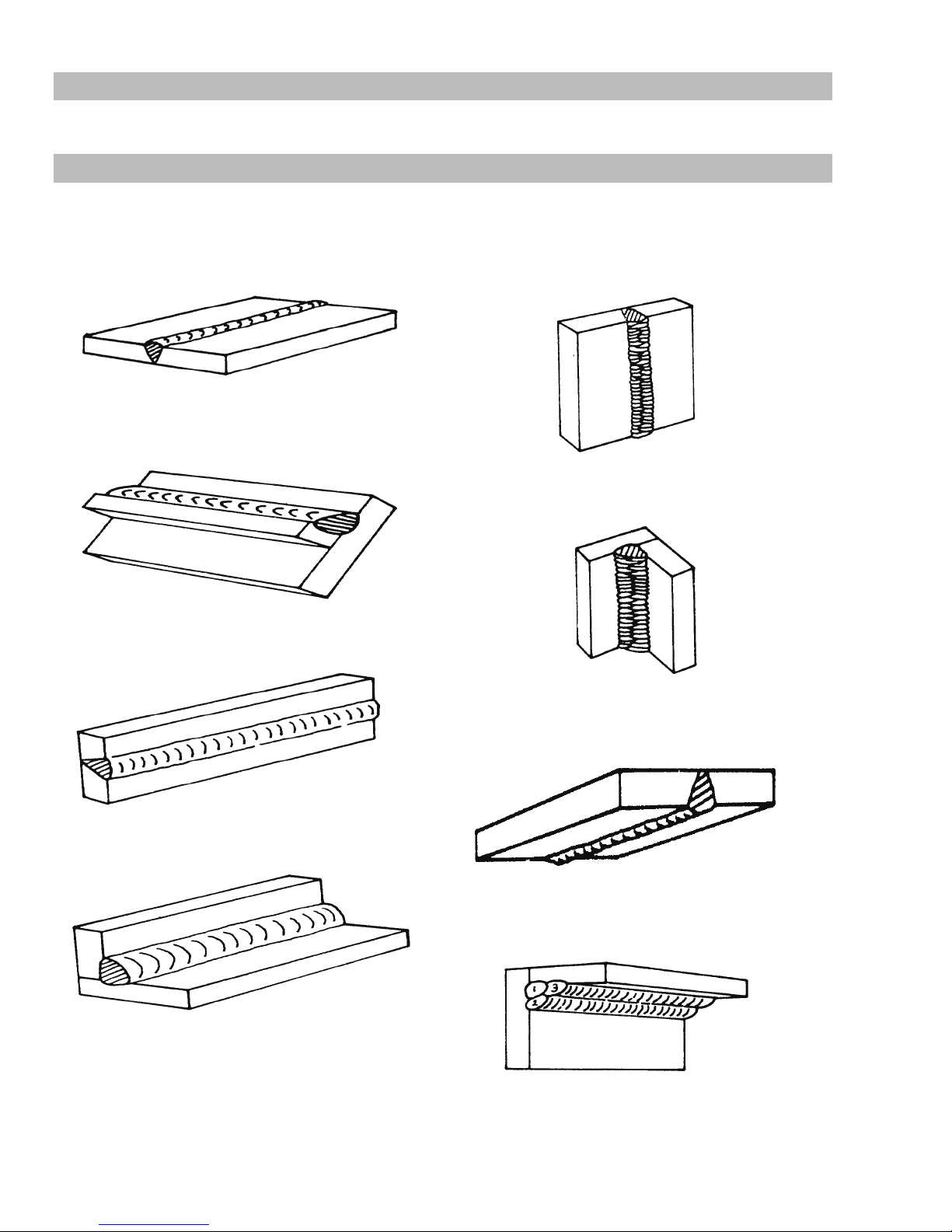
The electrodes dealt with in this publication can be used in most positions, i.e. they are suitable for welding in flat, horizontal, vertical
and overhead positions. Numerous applications call for welds to be made in positions intermediate between these. Some of the
common types of welds are shown in Figures 4-2 through 4-9.
Art # A-07687
Figure 4-2: Flat position, down hand butt weld
Art A-07691
Figure 4-6: Vertical position, butt weld
Art # A-07688
Figure 4-3: Flat position, gravity fillet weld
Art # A-07689
Figure 4-4: Horizontal position, butt weld
Figure 4-5: Horizontal - Vertical (HV) position
Art # A-07692
Figure 4-7: Vertical position, fillet weld
Art# A-07693
Figure 4-8: Overhead position, butt weld
Art # A-07690
OPERATION 4-4 Manual 0-5458
Art # A-07694
Figure 4-9: Overhead position, fillet weld
Page 25
ESAB ES 95i
Open Square Butt
x
Single Vee Butt Joint
Not less than
4.12 Joint Preparations
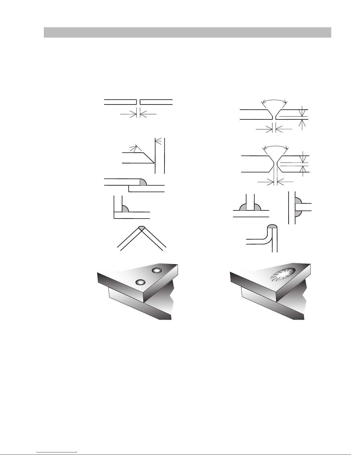
In many cases, it will be possible to weld steel sections without any special preparation. For heavier sections and for repair work on
castings, etc., it will be necessary to cut or grind an angle between the pieces being joined to ensure proper penetration of the weld
metal and to produce sound joints.
In general, surfaces being welded should be clean and free of rust, scale, dirt, grease, etc. Slag should be removed from oxy-cut
surfaces. Typical joint designs are shown in Figure 4-10.
Joint
Gap varies from
1.6mm (1/16”) to 4.8mm (3/16”)
depending on plate thickness
Single Vee Butt Joint
Lap Joint
Fillet Joint
Corner Weld
Not less than
45°
Double Vee Butt Joint
(Fillet both sides of the
Tee Joints
joint)
Edge Joint
1.6mm (1/16”)
1.6mm (1/16”)
70°
Not less than
70°
1.6mm (1/16” ) ma
1.6mm (1/16”) max
Plug Weld Plug Weld
Art # A-07695_AE
Figure 4-10: Typical joint designs for arc welding
Manual 0-5458 4-5 OPERATION
Page 26

ESAB ES 95i
20°
4.13 Arc Welding Technique
A Word to Beginners
For those who have not yet done any welding, the simplest way
to commence is to run beads on a piece of scrap plate. Use mild
steel plate about 6.0mm thick and a 3.2mm electrode. Clean any
paint, loose scale or grease off the plate and set it firmly on the
work bench so that welding can be carried out in the downhand
position. Make sure that the work clamp is making good
electrical contact with the work, either directly or through the
work table. For light gauge material, always clamp the work lead
directly to the job, otherwise a poor circuit will probably result.
4.14 The Welder
Place yourself in a comfortable position before beginning to weld.
Get a seat of suitable height and do as much work as possible
sitting down. Don’t hold your body tense. A taut attitude of mind
and a tensed body will soon make you feel tired. Relax and you
will find that the job becomes much easier. You can add much to
your peace of mind by wearing a leather apron and gauntlets. You
won’t be worrying then about being burnt or sparks setting alight
to your clothes.
Place the work so that the direction of welding is across, rather
than to or from, your body. The electrode holder lead should be
clear of any obstruction so that you can move your arm freely
along as the electrode burns down. If the lead is slung over your
shoulder, it allows greater freedom of movement and takes a
lot of weight off your hand. Be sure the insulation on your cable
and electrode holder is not faulty, otherwise you are risking an
electric shock.
4.15 Striking the Arc
Practice this on a piece of scrap plate before going on to more
exacting work. You may at first experience difficulty due to the tip
of the electrode “sticking” to the work piece. This is caused by
making too heavy a contact with the work and failing to withdraw
the electrode quickly enough. A low amperage will accentuate it.
This freezing-on of the tip may be overcome by scratching the
electrode along the plate surface in the same way as a match
is struck. As soon as the arc is established, maintain a 1/16"
(1.6mm) to 1/8" (3.2mm) gap between the burning electrode end
and the parent metal. Draw the electrode slowly along as it melts
down.
Another difficulty you may meet is the tendency, after the arc is
struck, to withdraw the electrode so far that the arc is broken
again. A little practice will soon remedy both of these faults.
Art # A-07696_AB
4.16 Arc Length
The securing of an arc length necessary to produce a neat weld
soon becomes almost automatic. You will find that arc produces
a crackling or spluttering noise and the weld metal comes across
in large, irregular blobs. The weld bead is flattened and spatter
increases. A short arc is essential if a high quality weld is to be
obtained although if it is too short there is the danger of it being
blanketed by slag and the electrode tip being solidified in. If
this should happen, give the electrode a quick twist back over
the weld to detach it. Contact or “touch-weld” electrodes such
as E7014 electrode do not stick in this way, and make welding
much easier.
4.17 Rate of Travel
After the arc is struck, your next concern is to maintain it, and
this requires moving the electrode tip towards the molten pool
at the same rate as it is melting away. At the same time, the
electrode has to move along the plate to form a bead. The
electrode is directed at the weld pool at about 20° from the
vertical. The rate of travel has to be adjusted so that a wellformed bead is produced.
If the travel is too fast, the bead will be narrow and strung out
and may even be broken up into individual globules. If the travel
is too slow, the weld metal piles up and the bead will be too
large.
4.18 Making Welded Joints
Having attained some skill in the handling of an electrode, you
will be ready to go on to make up welded joints.
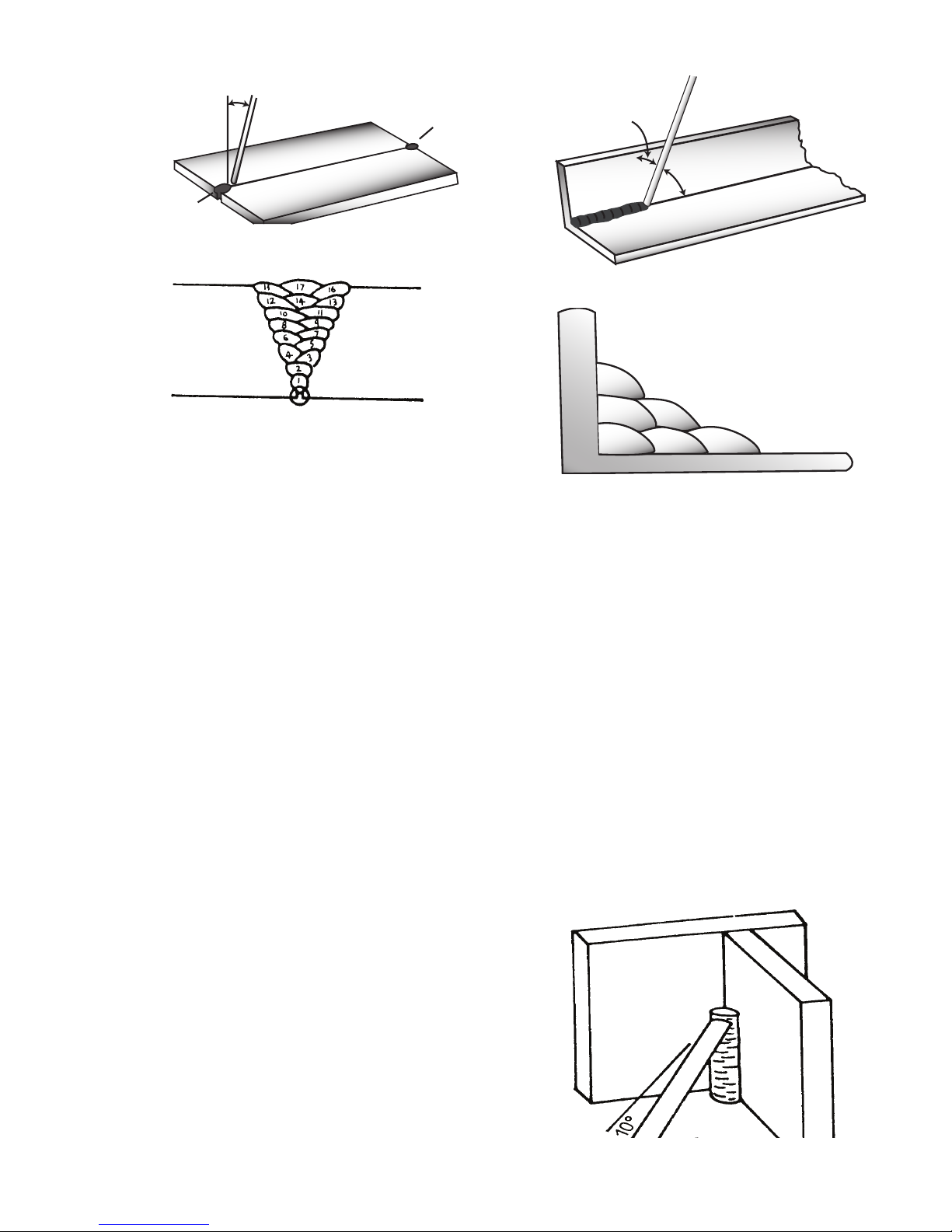
A. Butt Welds
Set up two plates with their edges parallel, as shown in Figure
4-12, allowing 1/15" (1.6mm) to 3/32" (2.4mm) gap between
them and tack weld at both ends. This is to prevent contraction
stresses from the cooling weld metal pulling the plates out of
alignment. Plates thicker than 1/4" (6.0mm) should have their
mating edges beveled to form a 70° to 90° included angle. This
allows full penetration of the weld metal to the root. Using a 1/8"
(3.2mm) E7014 electrode at 120 amps, deposit a run of weld
metal on the bottom of the joint.
Do not weave the electrode, but maintain a steady rate of travel
along the joint sufficient to produce a well-formed bead. At first
you may notice a tendency for undercut to form, but keeping the
arc length short, the angle of the electrode at about 20° from
vertical, and the rate of travel not too fast, will help eliminate this.
The electrode needs to be moved along fast enough to prevent
the slag pool from getting ahead of the arc. To complete the joint
in thin plate, turn the job over, clean the slag out of the back and
deposit a similar weld.
1.6 mm (1/16”)
Figure 4-11: Striking an arc
OPERATION 4-6 Manual 0-5458
Page 27
Art # A-07697_AB
T
ack Weld
20°-30°
Art # A-07699_AB
Electrode
Figure 4-12: Butt weld
Tack Weld
ESAB ES 95i
45° from
vertical
60° - 70° from line
of weld
Figure 4-14: Electrode position for HV fillet weld
Art # A-07700_AB
Art # A-07698
Figure 4-13: Weld build up sequence
Heavy plate will require several runs to complete the joint. After
completing the first run, chip the slag out and clean the weld
with a wire brush. It is important to do this to prevent slag being
trapped by the second run. Subsequent runs are then deposited
using either a weave technique or single beads laid down in the
sequence shown in Figure 4-13. The width of weave should not
be more than three times the core wire diameter of the electrode.
When the joint is completely filled, the back is either machined,
ground or gouged out to remove slag which may be trapped in
the root, and to prepare a suitable joint for depositing the backing
run. If a backing bar is used, it is not usually necessary to remove
this, since it serves a similar purpose to the backing run in
securing proper fusion at the root of the weld.
B. Fillet Welds
These are welds of approximately triangular cross-section made
by depositing metal in the corner of two faces meeting at right
angles. Refer to Figure 4-5.
A piece of angle iron is a suitable specimen with which to begin,
or two lengths of strip steel may be tacked together at right
angles. Using a 1/8" (3.2mm) E7014 electrode at 120 amps,
position angle iron with one leg horizontal and the other vertical.
This is known as a horizontal-vertical (HV) fillet. Strike the arc
and immediately bring the electrode to a position perpendicular
to the line of the fillet and about 45° from the vertical. Some
electrodes require to be sloped about 20° away from the
perpendicular position to prevent slag from running ahead of
the weld. Refer to Figure 4-14. Do not attempt to build up much
larger than 1/4" (6.4mm) width with a 1/8" (3.2mm) electrode,
otherwise the weld metal tends to sag towards the base, and
undercut forms on the vertical leg. Multi-runs can be made as
shown in Figure 4-15. Weaving in HV fillet welds is undesirable.
6
3
1
5
2
4
Figure 4-15: Multi-runs in HV fillet weld
C. Vertical Welds
1. Vertical Up
Tack weld a three feet length of angle iron to your
work bench in an upright position. Use a 1/8" (3.2mm)
E7014 electrode and set the current at 120 amps. Make
yourself comfortable on a seat in front of the job and
strike the arc in the corner of the fillet. The electrode
needs to be about 10° from the horizontal to enable a
good bead to be deposited. Refer Figure 4-16. Use a
short arc, and do not attempt to weave on the first run.
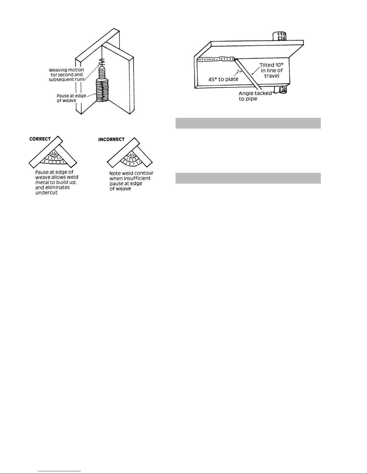
When the first run has been completed de-slag the
weld deposit and begin the second run at the bottom.
This time a slight weaving motion is necessary to cover
the first run and obtain good fusion at the edges. At the
completion of each side motion, pause for a moment
to allow weld metal to build up at the edges, otherwise
undercut will form and too much metal will accumulate
in the centre of the weld. Figure 4-17 illustrates
multi-run technique and Figure 4-18 shows the effects
of pausing at the edge of weave and of weaving too
rapidly.
Art # A-07701
Manual 0-5458 4-7 OPERATION
Figure 4-16: Single run vertical fillet weld
Page 28
ESAB ES 95i
Art # A-07702
Figure 4-17: Multi run vertical fillet weld
Art # A-07703
Figure 4-18: Examples of vertical fillet welds
2. Vertical Down
The E7014 electrode makes welding in this position
particularly easy. Use a 1/8" (3.2mm) electrode at 120
amps. The tip of the electrode is held in light contact
with the work and the speed of downward travel is
regulated so that the tip of the electrode just keeps
ahead of the slag. The electrode should point upwards
at an angle of about 45°.
3. Overhead Welds
Apart from the rather awkward position necessary,
overhead welding is not much more difficult that
downhand welding. Set up a specimen for overhead
welding by first tacking a length of angle iron at right
angles to another piece of angle iron or a length of
waste pipe. Then tack this to the work bench or hold in a
vice so that the specimen is positioned in the overhead
position as shown in the sketch. The electrode is held at
45° to the horizontal and tilted 10° in the line of travel
(Figure 4-19). The tip of the electrode may be touched
lightly on the metal, which helps to give a steady run.
A weave technique is not advisable for overhead fillet
welds. Use a 1/8" (3.2mm) E6012 electrode at 120
amps, and deposit the first run by simply drawing the
electrode along at a steady rate. You will notice that
the weld deposit is rather convex, due to the effect of
gravity before the metal freezes.
Art # A-07704
Figure 4-19: Overhead fillet weld
4.19 Distortion
Distortion in some degree is present in all forms of welding. In
many cases it is so small that it is barely perceptible, but in other
cases allowance has to be made before welding commences for
the distortion that will subsequently occur. The study of distortion
is so complex that only a brief outline can be attempted hear.
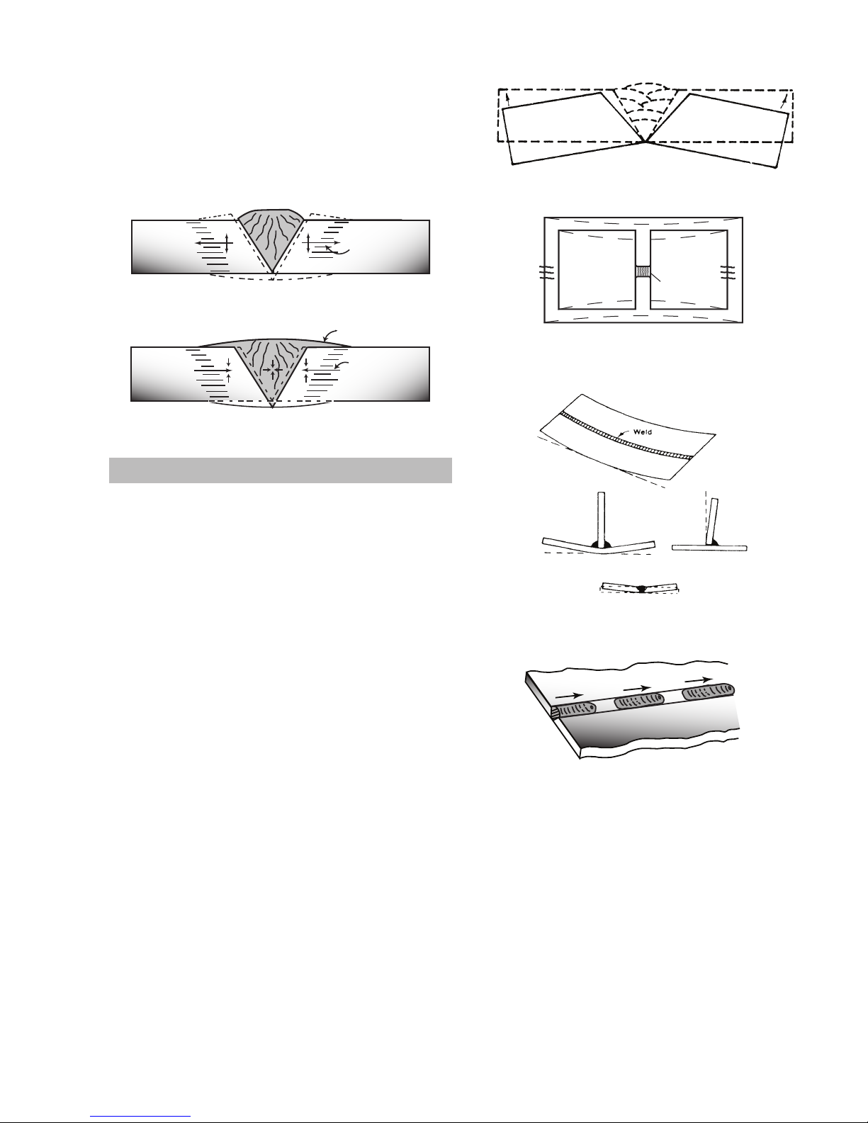
4.20 The Cause of Distortion
Distortion is cause by:
A. Contraction of Weld Metal:
Molten steel shrinks approximately 11 per cent in volume on
cooling to room temperature. This means that a cube of molten
metal would contract approximately 2.2 per cent in each of
its three dimensions. In a welded joint, the metal becomes
attached to the side of the joint and cannot contract freely.
Therefore, cooling causes the weld metal to flow plastically, that
is, the weld itself has to stretch if it is to overcome the effect of
shrinking volume and still be attached to the edge of the joint. If
the restraint is very great, as, for example, in a heavy section of
plate, the weld metal may crack. Even in cases where the weld
metal does not crack, there will still remain stresses “lockedup” in the structure. If the joint material is relatively weak, for
example, a butt joint in 2.0mm sheet, the contracting weld metal
may cause the sheet to become distorted.
B. Expansion and Contraction of Parent Metal in the
Fusion Zone:
While welding is proceeding, a relatively small volume of the
adjacent plate material is heated to a very high temperature and
attempts to expand in all directions. It is able to do his freely at
right angles to the surface of the plate (i.e., “through the weld”),
but when it attempts to expand “across the weld” or “along the
weld”, it meets considerable resistance, and to fulfil the desire
for continued expansion, it has to deform plastically, that is, the
metal adjacent to the weld is at a high temperature and hence
rather soft, and, by expanding, pushes against the cooler, harder
metal further away, and tends to bulge (or is “upset”). When the
weld area begins to cool, the “upset” metal attempts to contract
as much as it expanded, but, because it has been “upset”, it
does not resume its former shape, and the contraction of the new
OPERATION 4-8 Manual 0-5458
Page 29
Art # A-07708
B
PreheatPreheat
Dotted lines show effect if no preheat is used
Weld
C
Art # A-07710_AB
filled in when the welds are cool.
shape exerts a strong pull on adjacent metal. Several things can
Art # A-07705_AB
then happen.
The metal in the weld area is stretched (plastic deformation),
the job may be pulled out of shape by the powerful contraction
stresses (distortion), or the weld may crack, in any case, there
will remain “locked-up” stresses in the job. Figures 4-20 and 421 illustrate how distortion is created.
Upsetting
Expansion with
compression
Cool
Hot
Weld
Hot
Figure 4-20: Parent metal expansion
ESAB ES 95i
Art # A-07707
Figure 4-22: Principle of presetting
Art # A-07706_AC
Weld
Figure 4-21: Parent metal contraction
4.21 Overcoming Distortion Effects
There are several methods of minimizing distortion effects.
A. Peening
This is done by hammering the weld while it is still hot. The weld
metal is flattened slightly and because of this the tensile stresses
are reduced a little. The effect of peening is relatively shallow,
and is not advisable on the last layer.
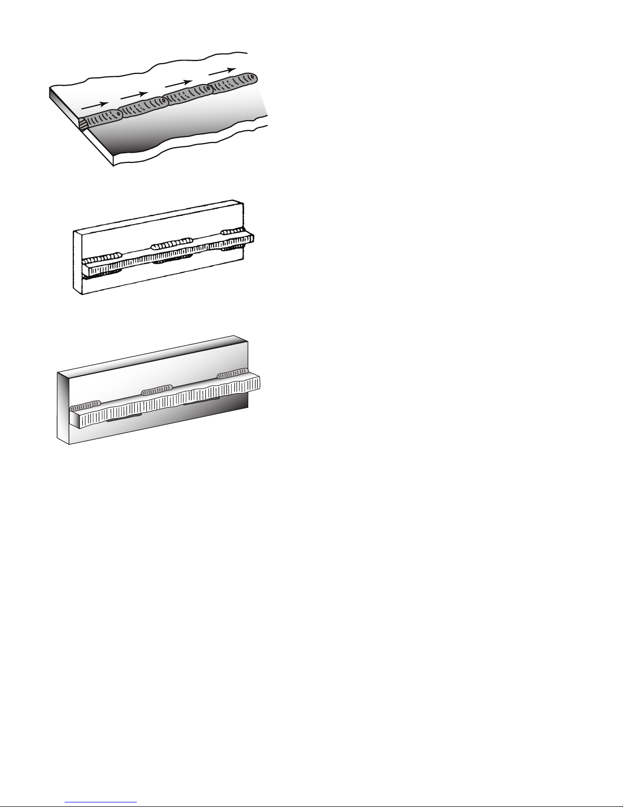
B. Distribution of Stresses
Distortion may be reduced by selecting a welding sequence
which will distribute the stresses suitably so that they tend to
cancel each other out. See Figures 4-25 through 4-28 for various
weld sequences. Choice of a suitable weld sequence is probably
the most effective method of overcoming distortion, although an
unsuitable sequence may exaggerate it. Simultaneous welding
of both sides of a joint by two welders is often successful in
eliminating distortion.
C. Restraint of Parts
Forcible restraint of the components being welded is often used
to prevent distortion. Jigs, positions, and tack welds are methods
employed with this in view.
D. Presetting
It is possible in some cases to tell from past experience or to
find by trial and error (or less frequently, to calculate) how much
distortion will take place in a given welded structure. By correct
pre-setting of the components to be welded, constructional
stresses can be made to pull the parts into correct alignment. A
simple example is shown in Figure 4-22.
E. Preheating
Suitable preheating of parts of the structure other than the area
to be welded can be sometimes used to reduce distortion. Figure
4-23 shows a simple application. By removing the heating source
from b and c as soon as welding is completed, the sections b and
c will contract at a similar rate, thus reducing distortion.
Manual 0-5458 4-9 OPERATION
Permanent Upset
Contraction
with tension
Figure 4-23: Reduction of distortion by preheating
Art # A-07709
Figure 4-24: Examples of distortion
1
2
Block Sequence.
The spaces between the welds are
3
Figure 4-25: Welding sequence
Page 30
ESAB ES 95i
Art # A-07711_AB
4
Figure 4-26: Step back sequence
Art # A-07712
Figure 4-27: Chain intermittent welding
1
2
3
Art # A-07713_AB
Figure 4-28: Staggered intermittent welding
OPERATION 4-10 Manual 0-5458
Page 31
ESAB ES 95i
!
SECTION 5:
SERVICE
5.01 Maintenance and Inspection
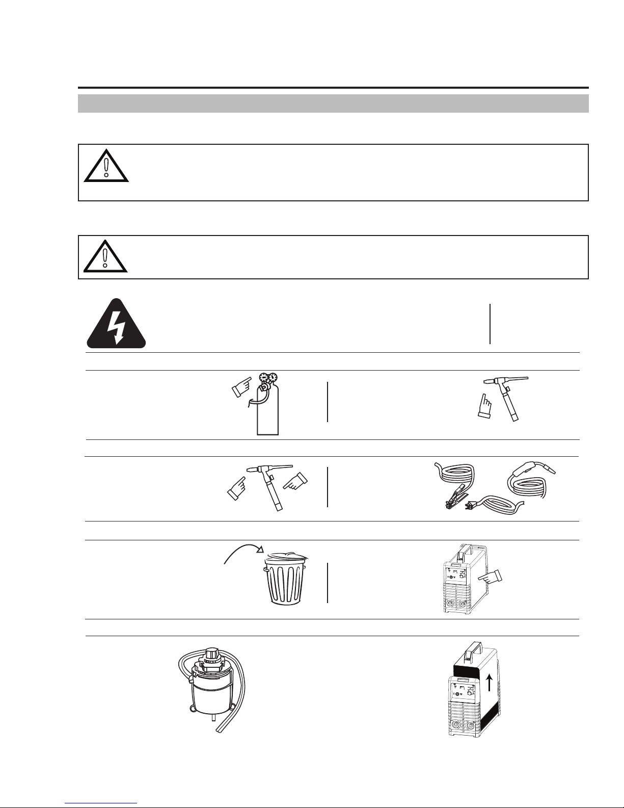
The only routine maintenance required for the power supply is a thorough cleaning and inspection, with the frequency depending on the
usage and the operating environment.
WARNING
There are extremely dangerous voltages and power levels present inside this product. Disconnect primary
power at the source before opening the enclosure. Wait at least two minutes before opening the enclosure
to allow the primary capacitors to discharge.
To clean the unit, open the enclosure and use a vacuum cleaner to remove any accumulated dirt and dust. The unit should also be
wiped clean, if necessary; with solvents that are recommended for cleaning electrical apparatus.
CAUTION
!
Do not blow air into the power supply during cleaning. Blowing air into the unit can cause metal particles to
interfere with sensitive electrical components and cause damage to the unit.
Warning!
Disconnect input power before maintaining.
Each Use
Visual check of
regulator and pressure
Weekly
Visually inspect
the torch body
and consumables
3 Months
Replace all
broken parts
Visual check of torch
Consumable parts
Visually inspect the
cables and leads.
Replace as needed
Clean
exterior
of power supply
Maintain more often
if used under severe
conditions
Art # A-08549_AD
Manual 0-5458 5-1 SERVICE
6 Months
Bring the unit to an authorized
Tweco Service Centre
to remove any accumulated dirt
and dust from the interior.
This may need to be done more
frequently under exceptionally
dirty conditions.
Page 32
ESAB ES 95i
Lack of side fusion,
scale dirt, small electrode,
amperage too lo
Not cleaned,
or incorrect
electrode
Slag
trapped in
undercut
Slag trapped in root
Art # A-05868_AC
Insufficient Gap
Incorrect Sequence
Art # A-05866_AC
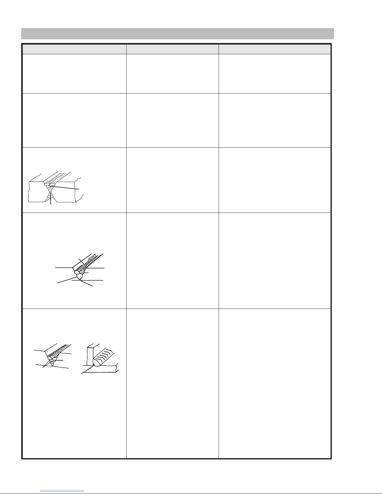
5.02 SMAW (Stick) Welding Problems
Description Possible Cause Remedy
1. Gas pockets or voids in weld metal
(Porosity).
A. Electrodes are damp.
B. Welding current is too high.
A. Dry electrodes before use.
B. Reduce welding current.
2. Crack occurring in weld metal soon
after solidification commences.
3. A gap is left by failure of the weld
metal to fill the root of the weld.
4. Portions of the weld run do not
fuse to the surface of the metal or
edge of the joint
Lack of fusion caused by dirt,
electrode angle incorrect,
rate of travel too high
Art # A-05867_AC
w
Lack of
inter-run fusion
Lack of root fusion
C. Surface impurities such as oil,
grease, paint, etc.
A. Rigidity of joint.
B. Insufficient throat thickness.
C. Cooling rate is too high.
A. Welding current is too low.
B. Electrode too large for joint.
C. Insufficient gap.
D. Incorrect sequence.
A. Small electrodes used on heavy
cold plate.
B. Welding current is too low.
C. Wrong electrode angle.
D. Travel speed of electrode is too
high.
E. Scale or dirt on joint surface.
C. Clean joint before welding
A. Redesign to relieve weld joint of severe
stresses or use crack resistance
electrodes.
B. Travel slightly slower to allow greater
build up in throat.
C. Preheat plate and cool slowly.
A. Increase welding current
B. Use smaller diameter electrode.
C. Allow wider gap.
D. Use correct build-up sequence.
A. Use larger electrodes and preheat the
plate.
B. Increase welding current
C. Adjust angle so the welding arc is
directed more into the base metal
D. Reduce travel speed of electrode
E. Clean surface before welding.
5. Non-metallic particles are trapped
in the weld metal (slag inclusion).
SERVICE 5-2 Manual 0-5458
A. Non-metallic particles may
be trapped in undercut from
previous run.
B. Joint preparation too restricted.
C. Irregular deposits allow slag to
be trapped.
D. Lack of penetration with slag
trapped beneath weld bead.
E. Rust or mill scale is preventing
full fusion.
F. Wrong electrode for position in
which welding is done.
A. If bad undercut is present, clean slag
out and cover with a run from a smaller
diameter electrode.
B. Allow for adequate penetration and
room for cleaning out the slag.
C. If very bad, chip or grind out
irregularities.
D. Use smaller electrode with sufficient
current to give adequate penetration.
Use suitable tools to remove all slag
from corners.
E. Clean joint before welding.
F. Use electrodes designed for position
in which welding is done, otherwise
proper control of slag is difficult.
Page 33

ESAB ES 95i
5.03 GTAW (Lift TIG) Welding Problems
Weld quality is dependent on the selection of the correct consumables, maintenance of equipment and proper welding technique.
Description Possible Cause Remedy
1. Excessive beard build-up or poor
penetration or poor fusion at
edges of weld.
2. Weld bead too wide and flat or
undercut at edges of weld or
excessive burn through.
3. Weld bead too small or
insufficient penetration or ripples
in bead are widely spaced apart.
4. Weld bead too wide or excessive
bead build up or excessive
penetration in butt joint.
5. Uneven leg length in fillet joint. Wrong placement of filler rod. Re-position filler rod.
6. Electrode melts when arc is
struck.
7. Dirty weld pool. A. Electrode contaminated through
8. Poor weld finish. Inadequate shielding gas. Increase gas flow or check gas line
9. Arc flutters during TIG welding. Tungsten electrode is too large
10. Welding arc cannot be
established.
11. Electrode melts or oxidizes when
an arc is struck.
Welding current is too low Increase weld current and/or change
joint preparation.
Welding current is too high. Decrease welding current.
Travel speed too fast. Reduce travel speed.
Travel speed is too slow. Increase travel speed.
Electrode is connected to the "+"
Positive Output Terminal.
contact with work piece or filler
rod material.
B. Gas contaminated with air.
for the welding current.
A. Work clamp is not connected to
the work piece or the work/torch
leads are not connected to the
correct welding terminals.
B. Torch lead is disconnected.
C. Gas flow incorrectly set, cylinder
empty or the torch valve is off.
A. No gas is flowing to welding
region.
B. Torch is clogged with dust.
C. Gas hose is cut.
D. Gas passage contains impurities.
E. Gas regulator turned off.
F. Torch valve is turned off.
G. The electrode is too small for the
welding current.
Connect the electrode to the
"-" Negative Output Terminal.
A. Clean the electrode by grinding
contaminates off.
B. Check gas lines for cuts and loose
fitting or change gas cylinder.
for problems
Select the right size electrode. Refer
to section Tungsten Electrode Current
Ranges.
A. Connect the work clamp to the work
piece or connect the work/torch leads
to the correct welding terminals.
B. Connect it to the "-" Negative Output
Terminal.
C. Select the right flow rate, change
cylinder or turn torch valve on.
A. Check the gas lines for kinks or
breaks or cylinder contains gas.
B. Clean torch.
C. Replace gas hose.
D. Disconnect gas hose from torch
then raise gas pressure and blow out
impurities.
E. Turn on.
F. Turn on.
G. Increase electrode diameter or reduce
the welding current.
Manual 0-5458 5-3 SERVICE
Page 34
ESAB ES 95i
!
Description Possible Cause Remedy
12. Arc start is not smooth. A. Tungsten electrode is too large
for the welding current.
B. The wrong electrode is being
used for the welding job.
C. Gas flow rate is too high.
D. Incorrect shield gas is being
used.
E. Poor work clamp connection
to work piece.
GTAW (Lift TIG) Welding Problems (Continued)
WARNING
There are extremely dangerous voltages and power levels present inside this product. Do not attempt to repair unless you are an Accredited Thermal Arc Service Agent and you have had training in power measurements and troubleshooting techniques. If major complex subassemblies are faulty, then the Welding Power
Source must be returned to an Accredited Thermal Arc Service Agent for repair.
5.04 Power Source Problems
Description Possible Cause Remedy
1. The welding arc cannot be
established.
A. The Primary supply voltage
has not been switched ON.
B. The Welding Power Source
switch is switched OFF.
C. Loose connections internally.
A. Refer to section Tungsten Electrode
Current Ranges for the correct size.
B. Refer to section Tungsten Electrode Types
for the correct electrode type.
C. Select the correct flow rate for the welding
job.
D. Use 100% argon for TIG welding.
E. Improve connection to work piece.
A. Switch ON the Primary supply
voltage.
B. Switch ON the Welding Power
Source.
C. Have an Accredited Thermal
Arc Service Provider repair the
connection.
2. The welding arc cannot be
established when the Over Heat
Indicator is illuminated
3. Maximum output welding
current cannot be achieved with
nominal Mains supply voltage.
4. Welding current reduces when
welding.
5. Circuit breaker (or fuse) trips
during welding.
The machines duty cycle has been
exceeded
Defective control circuit Have an Accredited Thermal Arc
Poor work lead connection to the
work piece.
The circuit breaker (or fuse) is
under size.
Wait for the Over Heat Indicator
to extinguish before resuming
welding
Service Provider inspect then
repair the welder.
Ensure that the work lead has a
positive electrical connection to
the work piece.
The recommended circuit breaker
(or fuse) size is 20 amp. An
individual branch circuit capable
of carrying 20 amperes and
protected by fuses or circuit
breaker is recommended for this
application.
SERVICE 5-4 Manual 0-5458
Page 35

APPENDIX 1: REPLACEMENT PARTS
Description Part No.
Case Toolbox, 95i W4012801
Fan, 24V DC, 95i W7003004
Rectifier Bridge, 700V, 50A, 95i W7003010
Current Sensor, 95i CSA W7003077
Thermistor, 95i W7003016
Terminal, Output, 95i W7003019
Handle, 95i CSA W7003078
Knob, Control, Red, 20 OD x 6 ID W7003079
Panel, Base, 95i CSA W7003080
Panel, Cover, 95i W7003043
Panel, Front, 95i CSA W7003081
Panel, Rear, 95i CSA W7003082
PCB, Control, 95i W7003046
PCB, Front Control, 95i CSA W7003083
PCB, Power, 95i CSA W7003084
Strap, Shoulder, 95i W7003049
Switch, On/Off, 95i W7003050
ESAB ES 95i
Manual 0-5458 A-1 APPENDIX
Page 36
ESAB ES 95i
17V style TIG Torch with 3m lead, gas valve, 25mm dinse connection and accessory kit W4012500
Argon Shielding Gas Regulator with 5/8"-18 UNF Hose Connection 600300
Power Adapter-115V,20A Socket to 15A Plug W4013300
USA Graphics Auto-Darkening welding helmet, spare cover lens and operating manual W4011700
Canadian Graphics Auto-Darkening welding helmet, spare cover lens and operating manual W4011800
Claret Color Auto-Darkening welding helmet, spare cover lens and operating manual W4011900
Black Graphics Auto-Darkening welding helmet, spare cover lens and operating manual W4012000
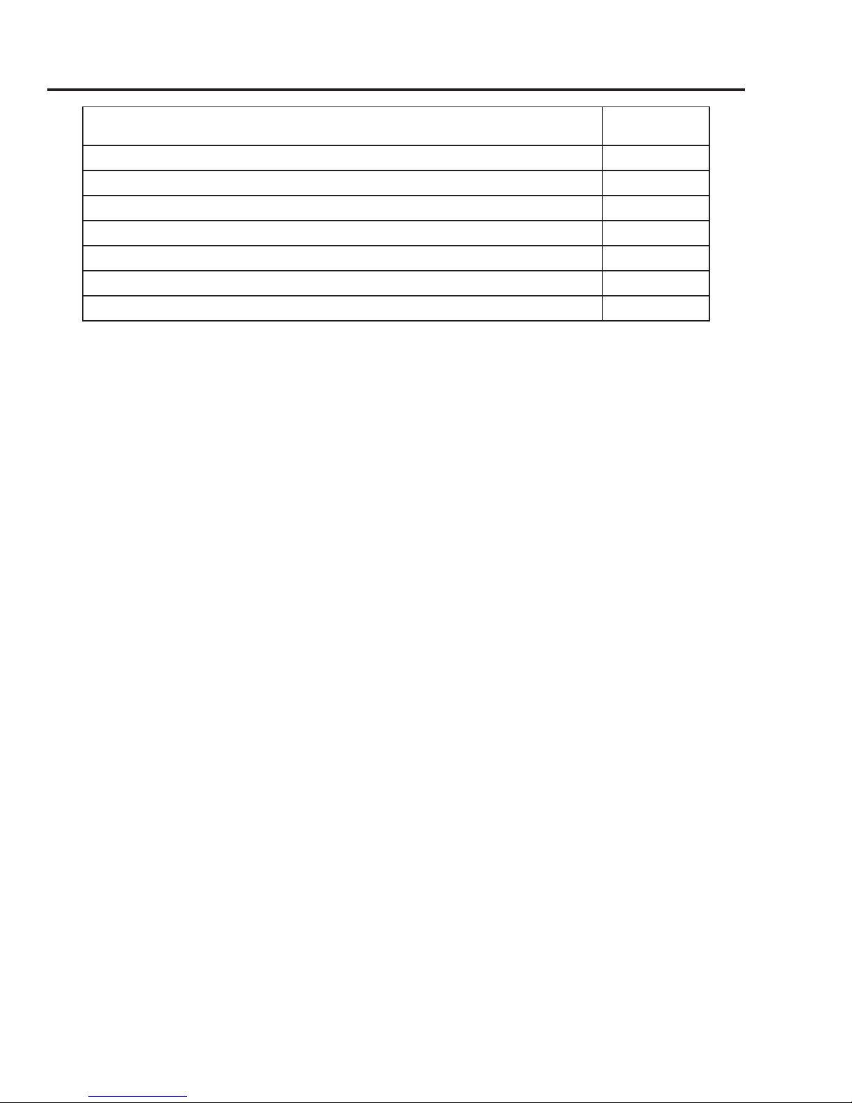
APPENDIX 2: OPTIONS AND ACCESSORIES
Description Part Number
APPENDIX A-2 Manual 0-5458
Page 37
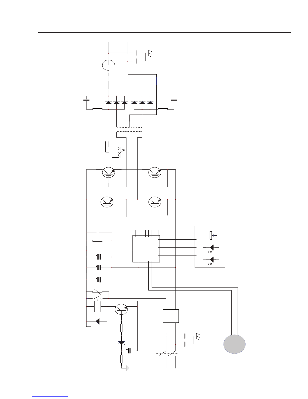
APPENDIX 3: SYSTEM SCHEMATIC
AC1AC
3
+
2
-
4
-24V
L?
TRANS2
OC
Pr2
OC1
OC2
Pr1
DR1
DR2
DR5
DR6
DR3
DR4
DR7
DR8
DR1
DR2
DR3
DR4
DR5
DR8
DR6
DR7
OC1OC2
K1 AC 115V/60HZ
OUT
OUT
FAN
LED1
LED2
VR1
PTC
IGBT
IGBT
IGBT
IGBT
FJ
Art # A-09016
ESAB ES 95i
Manual 0-5458 A-3 APPENDIX
Page 38

ESAB ES 95i
This Page Intentionally Blank
APPENDIX A-4 Manual 0-5458
Page 39

Page 40

ESAB subsidiaries and representative offices
Europe
AUSTRIA
ESAB Ges.m.b.H
Vienna-Liesing
Tel: +43 1 888 25 11
Fax: +43 1 888 25 11 85
BELGIUM
S.A. ESAB N.V.
Heist-op-den-Berg
Tel: +32 70 233 075
Fax: +32 15 257 944
BULGARIA
ESAB Kft Representative Office
Sofia
Tel/Fax: +359 2 974 42 88
THE CZECH REPUBLIC
ESAB VAMBERK s.r.o.
Vamberk
Tel: +420 2 819 40 885
Fax: +420 2 819 40 120
DENMARK
Aktieselskabet ESAB
Herlev
Tel: +45 36 30 01 11
Fax: +45 36 30 40 03
FINLAND
ESAB Oy
Helsinki
Tel: +358 9 547 761
Fax: +358 9 547 77 71
FRANCE
ESAB France S.A.
Cergy Pontoise
Tel: +33 1 30 75 55 00
Fax: +33 1 30 75 55 24
GERMANY
ESAB GmbH
Solingen
Tel: +49 212 298 0
Fax: +49 212 298 218
GREAT BRITAIN
ESAB Group (UK) Ltd
Waltham Cross
Tel: +44 1992 76 85 15
Fax: +44 1992 71 58 03
ESAB Automation Ltd
Andover
Tel: +44 1264 33 22 33
Fax: +44 1264 33 20 74
HUNGARY
ESAB Kft
Budapest
Tel: +36 1 20 44 182
Fax: +36 1 20 44 186
ITALY
ESAB Saldatura S.p.A.
Bareggio (Mi)
Tel: +39 02 97 96 8.1
Fax: +39 02 97 96 87 01
THE NETHERLANDS
ESAB Nederland B.V.
Amersfoort
Tel: +31 33 422 35 55
Fax: +31 33 422 35 44
NORWAY
AS ESAB
Larvik
Tel: +47 33 12 10 00
Fax: +47 33 11 52 03
POLAND
ESAB Sp.zo.o.
Katowice
Tel: +48 32 351 11 00
Fax: +48 32 351 11 20
PORTUGAL
ESAB Lda
Lisbon
Tel: +351 8 310 960
Fax: +351 1 859 1277
ROMANIA
ESAB Romania Trading SRL
Bucharest
Tel: +40 316 900 600
Fax: +40 316 900 601
RUSSIA
LLC ESAB
Moscow
Tel: +7 (495) 663 20 08
Fax: +7 (495) 663 20 09
SLOVAKIA
ESAB Slovakia s.r.o.
Bratislava
Tel: +421 7 44 88 24 26
Fax: +421 7 44 88 87 41
SPAIN
ESAB Ibérica S.A.
Alcalá de Henares (MADRID)
Tel: +34 91 878 3600
Fax: +34 91 802 3461
SWEDEN
ESAB Sverige AB
Gothenburg
Tel: +46 31 50 95 00
Fax: +46 31 50 92 22
ESAB international AB
Gothenburg
Tel: +46 31 50 90 00
Fax: +46 31 50 93 60
SWITZERLAND
ESAB AG
Dietikon
Tel: +41 1 741 25 25
Fax: +41 1 740 30 55
UKRAINE
ESAB Ukraine LLC
Kiev
Tel: +38 (044) 501 23 24
Fax: +38 (044) 575 21 88
North and South America
ARGENTINA
CONARCO
Buenos Aires
Tel: +54 11 4 753 4039
Fax: +54 11 4 753 6313
BRAZIL
ESAB S.A.
Contagem-MG
Tel: +55 31 2191 4333
Fax: +55 31 2191 4440
CANADA
ESAB Group Canada Inc.
Missisauga, Ontario
Tel: +1 905 670 02 20
Fax: +1 905 670 48 79
MEXICO
ESAB Mexico S.A.
Monterrey
Tel: +52 8 350 5959
Fax: +52 8 350 7554
USA
ESAB Welding & Cutting Products
Florence, SC
Tel: +1 843 669 44 11
Fax: +1 843 664 57 48
Asia/Pacific
AUSTRALIA
ESAB South Pacific
Archerfield BC QLD 4108
Tel: +61 1300 372 228
Fax: +61 7 3711 2328
CHINA
Shanghai ESAB A/P
Shanghai
Tel: +86 21 2326 3000
Fax: +86 21 6566 6622
INDIA
ESAB India Ltd
Calcutta
Tel: +91 33 478 45 17
Fax: +91 33 468 18 80
INDONESIA
P.T. ESABindo Pratama
Jakarta
Tel: +62 21 460 0188
Fax: +62 21 461 2929
JAPAN
ESAB Japan
Tokyo
Tel: +81 45 670 7073
Fax: +81 45 670 7001
MALAYSIA
ESAB (Malaysia) Snd Bhd
USJ
Tel: +603 8023 7835
Fax: +603 8023 0225
SINGAPORE
ESAB Asia/Pacific Pte Ltd
Singapore
Tel: +65 6861 43 22
Fax: +65 6861 31 95
SOUTH KOREA
ESAB SeAH Corporation
Kyungnam
Tel: +82 55 269 8170
Fax: +82 55 289 8864
UNITED ARAB EMIRATES
ESAB Middle East FZE
Dubai
Tel: +971 4 887 21 11
Fax: +971 4 887 22 63
Africa
EGYPT
ESAB Egypt
Dokki-Cairo
Tel: +20 2 390 96 69
Fax: +20 2 393 32 13
SOUTH AFRICA
ESAB Africa Welding & Cutting
Ltd
Durbanvill 7570 - Cape Town
Tel: +27 (0)21 975 8924
Distributors
For addresses and phone numbers to our distributors in other
countries, please visit our home
page
www.esab.eu
www.esab.eu
©2015 ESAB Welding and Cutting Products
Printed in China
 Loading...