

Page 1
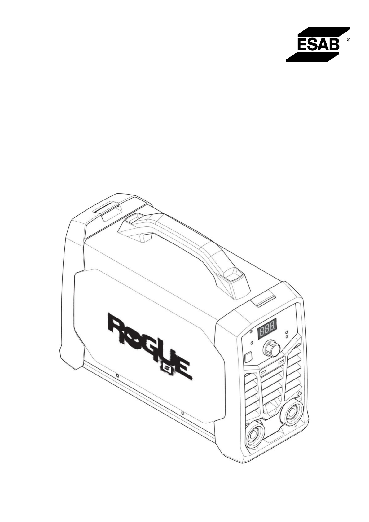
Rogue
ES 150i, ES 180i
Instruction manual
0463 732 201 GB 20220318
Valid for: HA017-, HA018-xxxx-xxxx
Page 2
Page 3
Page 4

TABLE OF CONTENTS
1
SAFETY
1.1 Meaning of symbols
1.2 Safety precautions
2
INTRODUCTION
2.1 Equipment
3
TECHNICAL DATA
4
INSTALLATION
4.1 Location
4.2 Lifting instructions
4.3 Mains supply
5
OPERATION
5.1 Overview
5.2 Connections and control devices
5.3 Connecting welding and return cables
5.4 Turning the power on/off
5.5 Fan control
5.6 Thermal protection
5.7 Functions and symbols
5.8 Setting panel
.......................................................................................................
...............................................................................
.................................................................................
..........................................................................................
...............................................................................................
......................................................................................
............................................................................................
...................................................................................................
.................................................................................
...........................................................................................
................................................................................................
.................................................................................................
.......................................................................
..............................................................................................
.................................................................................
.........................................................................
...........................................................................................
.........................................................
................................................
5
5
5
9
9
10
12
12
12
13
15
15
15
15
16
16
16
16
18
6
MAINTENANCE
6.1 Routine maintenance
6.2 Cleaning instruction
7
TROUBLESHOOTING
8
ORDERING SPARE PARTS
DIAGRAM
............................................................................................................
...........................................................................................
ORDERING NUMBERS
ACCESSORIES
...................................................................................................
.............................................................................
...............................................................................
.................................................................................
........................................................................
.......................................................................................
19
19
19
21
22
23
24
25
Rights reserved to alter specifications without notice.
0463 732 201 © ESAB AB 2022
Page 5
1 SAFETY
1 SAFETY
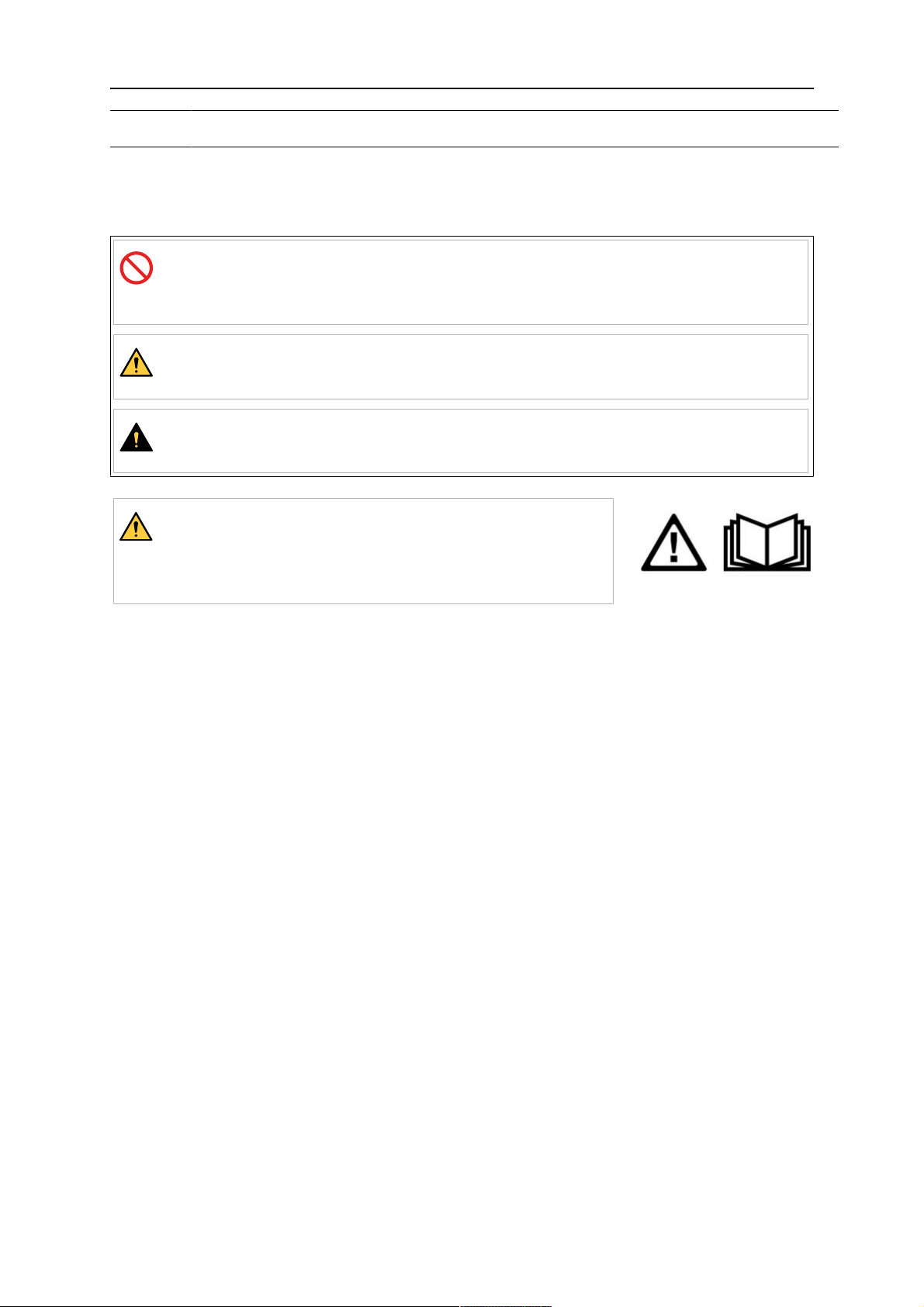
1.1 Meaning of symbols
As used throughout this manual: Means Attention! Be Alert!
DANGER!
Means immediate hazards which, if not avoided, will result in immediate,
serious personal injury or loss of life.
WARNING!
Means potential hazards which could result in personal injury or loss of life.
CAUTION!
Means hazards which could result in minor personal injury.
WARNING!
Before use, read and understand the instruction manual
and follow all labels, employer´s safety practices and
Safety Data Sheets (SDSs).
1.2 Safety precautions
Users of ESAB equipment have the ultimate responsibility for ensuring that anyone who
works on or near the equipment observes all the relevant safety precautions. Safety
precautions must meet the requirements that apply to this type of equipment. The following
recommendations should be observed in addition to the standard regulations that apply to
the workplace.
All work must be carried out by trained personnel well-acquainted with the operation of the
equipment. Incorrect operation of the equipment may lead to hazardous situations which can
result in injury to the operator and damage to the equipment.
1. Anyone who uses the equipment must be familiar with:
○ its operation
○ location of emergency stops
○ its function
○ relevant safety precautions
○ welding and cutting or other applicable operation of the equipment
2. The operator must ensure that:
○ no unauthorised person is stationed within the working area of the equipment
when it is started up
○ no-one is unprotected when the arc is struck or work is started with the
equipment
3. The workplace must:
○ be suitable for the purpose
○ be free from drafts
0463 732 201
- 5 -
© ESAB AB 2022
Page 6
1 SAFETY
4. Personal safety equipment:
○ Always wear recommended personal safety equipment, such as safety glasses,
flame-proof clothing, safety gloves
○ Do not wear loose-fitting items, such as scarves, bracelets, rings, etc., which
could become trapped or cause burns
5. General precautions:
○ Make sure the return cable is connected securely
○ Work on high voltage equipment may only be carried out by a qualified
electrician
○ Appropriate fire extinguishing equipment must be clearly marked and close at
hand
○ Lubrication and maintenance must not be carried out on the equipment during
operation
If equipped with ESAB cooler
Use ESAB approved coolant only. Non-approved coolant might damage the equipment and
jeopardize product safety. In case of such damage, all warranty undertakings from ESAB
cease to apply.
Recommended ESAB coolant ordering number: 0465720002.
For ordering information, see the "ACCESSORIES" chapter in the instruction manual.
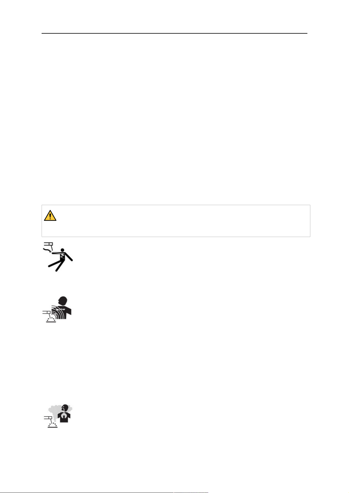
WARNING!
Arc welding and cutting can be injurious to yourself and others. Take precautions
when welding and cutting.
ELECTRIC SHOCK - Can kill
• Install and ground the unit in accordance with instruction manual.
• Do not touch live electrical parts or electrodes with bare skin, wet gloves or
wet clothing.
• Insulate yourself from work and ground.
• Ensure your working position is safe
ELECTRIC AND MAGNETIC FIELDS - Can be dangerous to health
• Welders having pacemakers should consult their physician before welding.
EMF may interfere with some pacemakers.
• Exposure to EMF may have other health effects which are unknown.
• Welders should use the following procedures to minimize exposure to
EMF:
○ Route the electrode and work cables together on the same side of
your body. Secure them with tape when possible. Do not place your
body between the torch and work cables. Never coil the torch or work
cable around your body. Keep welding power source and cables as
far away from your body as possible.
○ Connect the work cable to the workpiece as close as possible to the
area being welded.
0463 732 201
FUMES AND GASES - Can be dangerous to health
• Keep your head out of the fumes.
• Use ventilation, extraction at the arc, or both, to take fumes and gases
away from your breathing zone and the general area.
- 6 -
© ESAB AB 2022
Page 7
1 SAFETY
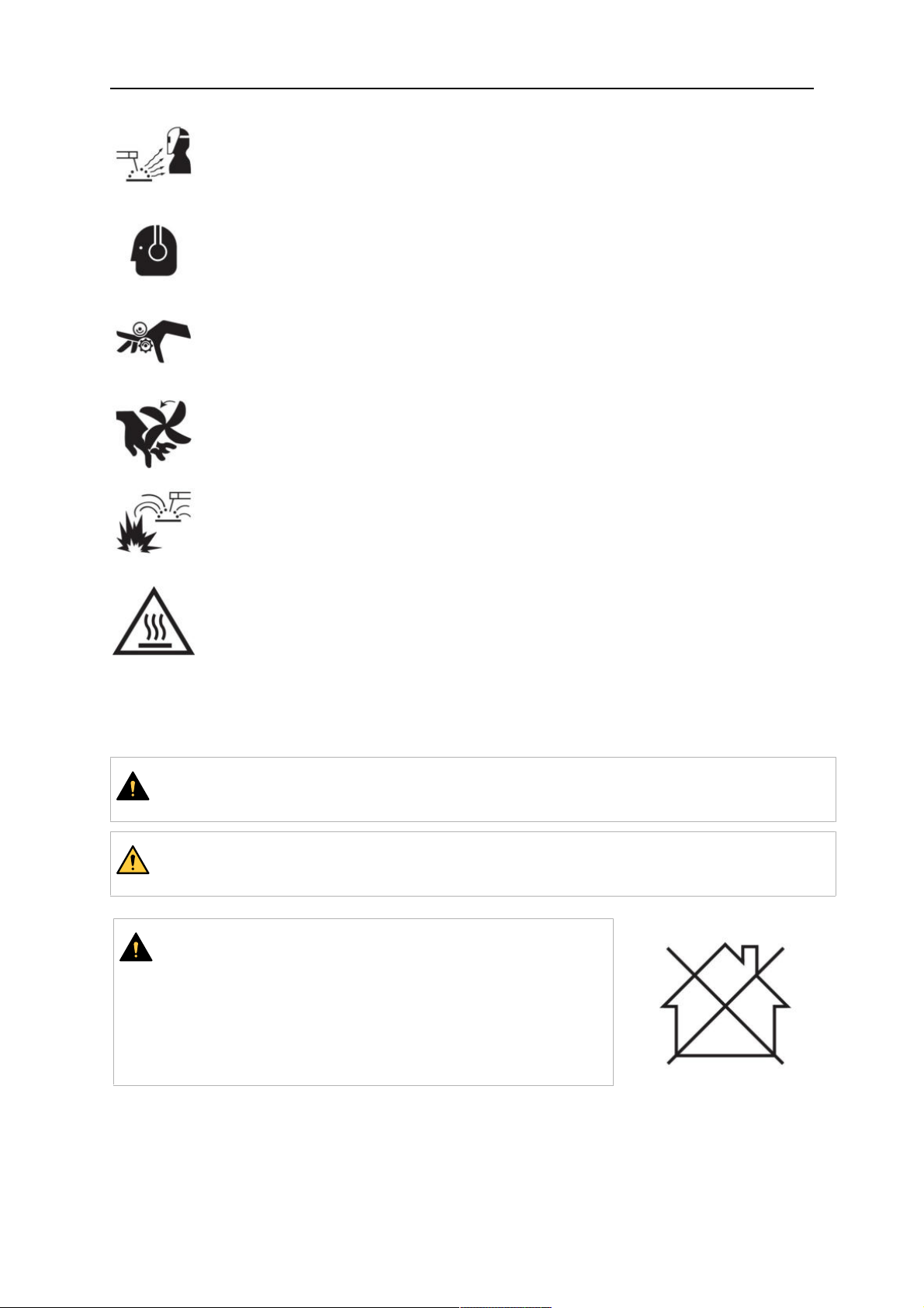
ARC RAYS - Can injure eyes and burn skin
• Protect your eyes and body. Use the correct welding screen and filter lens
and wear protective clothing.
• Protect bystanders with suitable screens or curtains.
NOISE - Excessive noise can damage hearing
Protect your ears. Use earmuffs or other hearing protection.
MOVING PARTS - Can cause injuries
• Keep all doors, panels and covers closed and securely in place. Have only
qualified people remove covers for maintenance and troubleshooting as
necessary. Reinstall panels or covers and close doors when service is
finished and before starting engine.
• Stop engine before installing or connecting unit.
• Keep hands, hair, loose clothing and tools away from moving parts.
FIRE HAZARD
• Sparks (spatter) can cause fire. Make sure that there are no inflammable
materials nearby.
• Do not use on closed containers.
HOT SURFACE - Parts can burn
• Do not touch parts bare handed.
• Allow cooling period before working on equipment.
• To handle hot parts, use proper tools and/or insulated welding gloves to
prevent burns.
MALFUNCTION - Call for expert assistance in the event of malfunction.
PROTECT YOURSELF AND OTHERS!
CAUTION!
This product is solely intended for arc welding.
WARNING!
Do not use the power source for thawing frozen pipes.
CAUTION!
Class A equipment is not intended for use in residential
locations where the electrical power is provided by the
public low-voltage supply system. There may be
potential difficulties in ensuring electromagnetic
compatibility of class A equipment in those locations,
due to conducted as well as radiated disturbances.
0463 732 201
- 7 -
© ESAB AB 2022
Page 8

1 SAFETY
NOTE!
Dispose of electronic equipment at the recycling
facility!
In observance of European Directive 2012/19/EC on
Waste Electrical and Electronic Equipment and its
implementation in accordance with national law,
electrical and/or electronic equipment that has reached
the end of its life must be disposed of at a recycling
facility.
As the person responsible for the equipment, it is your
responsibility to obtain information on approved
collection stations.
For further information contact the nearest ESAB dealer.
ESAB has an assortment of welding accessories and personal protection equipment
for purchase. For ordering information contact your local ESAB dealer or visit us on
our website.
0463 732 201
- 8 -
© ESAB AB 2022
Page 9

2 INTRODUCTION
2 INTRODUCTION
Overview
Rogue ES 150i, ES 180i are an inverter-based power source intended for MMA (Manual
Metal Arc) and TIG (Tungsten Inert Gas) welding.
ESAB accessories for the product can be found in the "ACCESSORIES" chapter of
this manual.
2.1 Equipment
Rogue ES 150i, ES 180i includes:
• Power Source
• Work Clamp Leadset
• Electrode Holder Leadset
• Safety Manual
• Quick Start Guide
• Shoulder Strap
0463 732 201
- 9 -
© ESAB AB 2022
Page 10

3 TECHNICAL DATA
3 TECHNICAL DATA
Technical data
Rogue ES 180i Rogue ES 150i
Outlet voltage 230V±15%
1~ 50/60Hz
230V±15%
1~ 50/60Hz
Primary current
I
max
I
max
MMA
LiveTIG
36A 30A
24A 18.5A
No-loadpower demand when in
energy saving mode 30W 30W
Setting range
MMA 20-180A 20-150A
Live TIG 10-180A 10-150A
Permissible load at MMA
20%dutycycle 170A/ 26.8V
25% duty cycle 150A/ 26V
60% duty cycle 97A/ 23.9V 97A/ 23.9V
100% duty cycle 75A/ 23V 75A/ 23V
Permissible load at Live TIG
25% duty cycle 180A/ 17.2V 150A/ 16V
60% duty cycle 116A/ 14.6V 97A/ 13.9V
100% duty cycle 90A/ 13.6V 75A/ 13V
Apparent power I2at maximum
current 8.7kVA 6.9kVA
Active
power I
2
at maximum current 5.5kW 4.35kW
Power factor at maximum current
Live TIG 0.63 0.63
MMA 0.63 0.63
Efficiency at maximum current
MMA 89% 89%
Live TIG 89% 89%
Open-circuit voltage U0max
VRD 35 V deactivated 63VDC 63VDC
VRD 35 V activated <30V <30V
Operating temperature -10to+40°C
-10to+40°C
(+14to 104°F)
Transportation temperature -20 to +55°C
(-4 to +131°F)
0463 732 201
- 10 -
(+14to 104°F)
-20 to +55°C
(-4 to +131°F)
© ESAB AB 2022
Page 11

3 TECHNICAL DATA
Rogue ES 180i Rogue ES 150i
Continual sound pressure at
<70dB <70dB
no-load
Dimensions l×w×h 403×153×264mm
(15.8×6×10.4in.)
403×153×264mm
(15.8×6×10.4in.)
Weight 6.8kg 6.8kg
Insulation class transformer H H
Enclosure class IP23S IP23S
Application class
Mains supply, S
sc min
Minimum short circuit power on the network in accordance with IEC 61000-3-12.
Duty cycle
The duty cycle refers to the time as a percentage of a ten-minute period that you can weld or
cut at a certain load without overloading. The duty cycle is valid for 40°C/104°F, or below.
Enclosure class
The IP code indicates the enclosure class, i.e. the degree of protection against penetration
by solid objects or water.
Equipment marked IP23S is intended for indoor and outdoor use; however, should not be
operated in precipitation.
Application class
The symbol
indicates that the power source is designed for use in areas with increased
electrical hazard.
0463 732 201
- 11 -
© ESAB AB 2022
Page 12
4 INSTALLATION
4 INSTALLATION
The installation must be carried out by a professional.
CAUTION!
This product is intended for industrial use. In a domestic environment this product may
cause radio interference. It is the user's responsibility to take adequate precautions.
4.1 Location
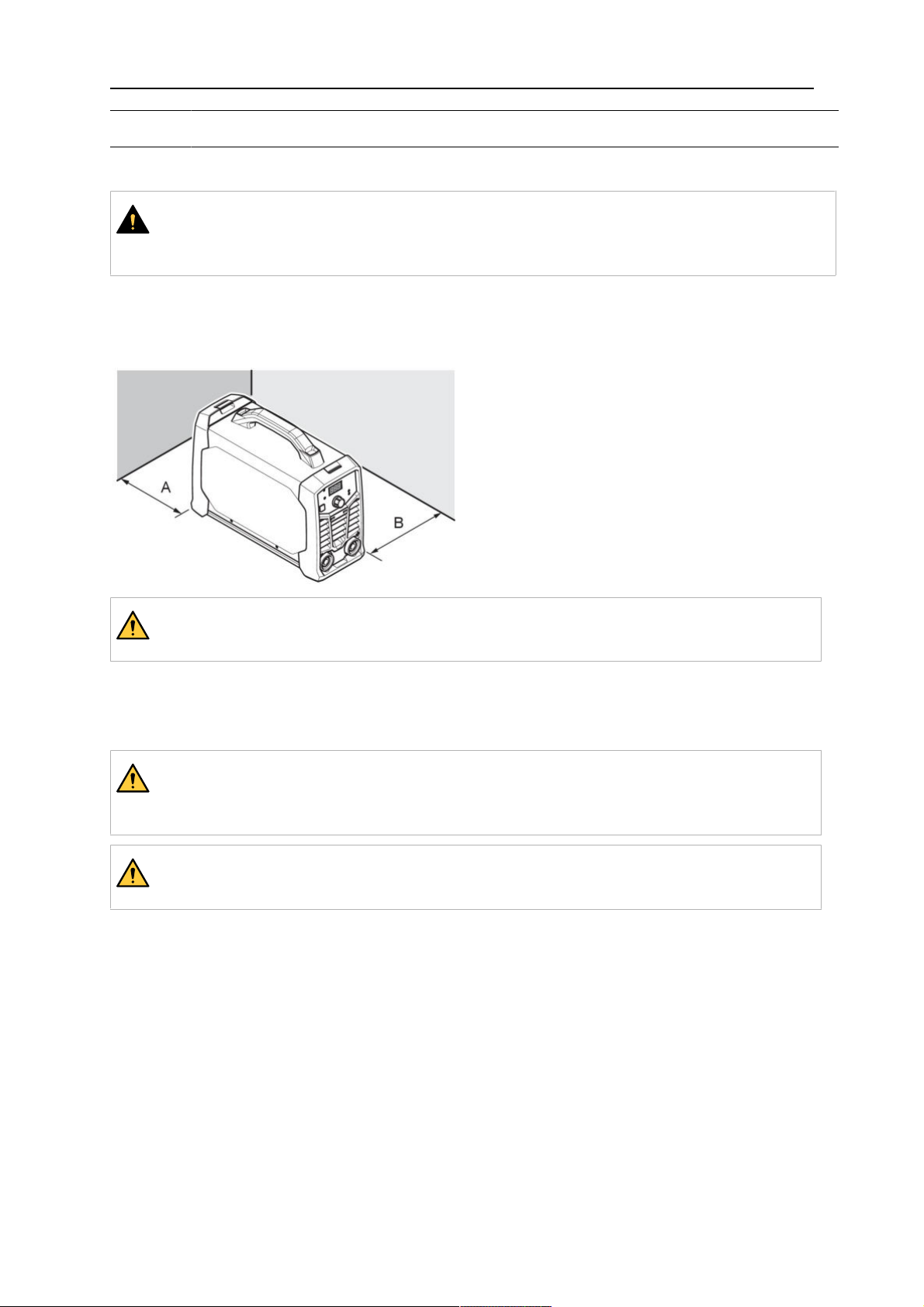
Position the power source so that cooling air inlets and outlets are not obstructed.
A. Minimum 200 mm (8 in.)
B. Minimum 200 mm (8 in.)
WARNING!
Secure the equipment - particularly if the ground is uneven or sloping.
4.2 Lifting instructions
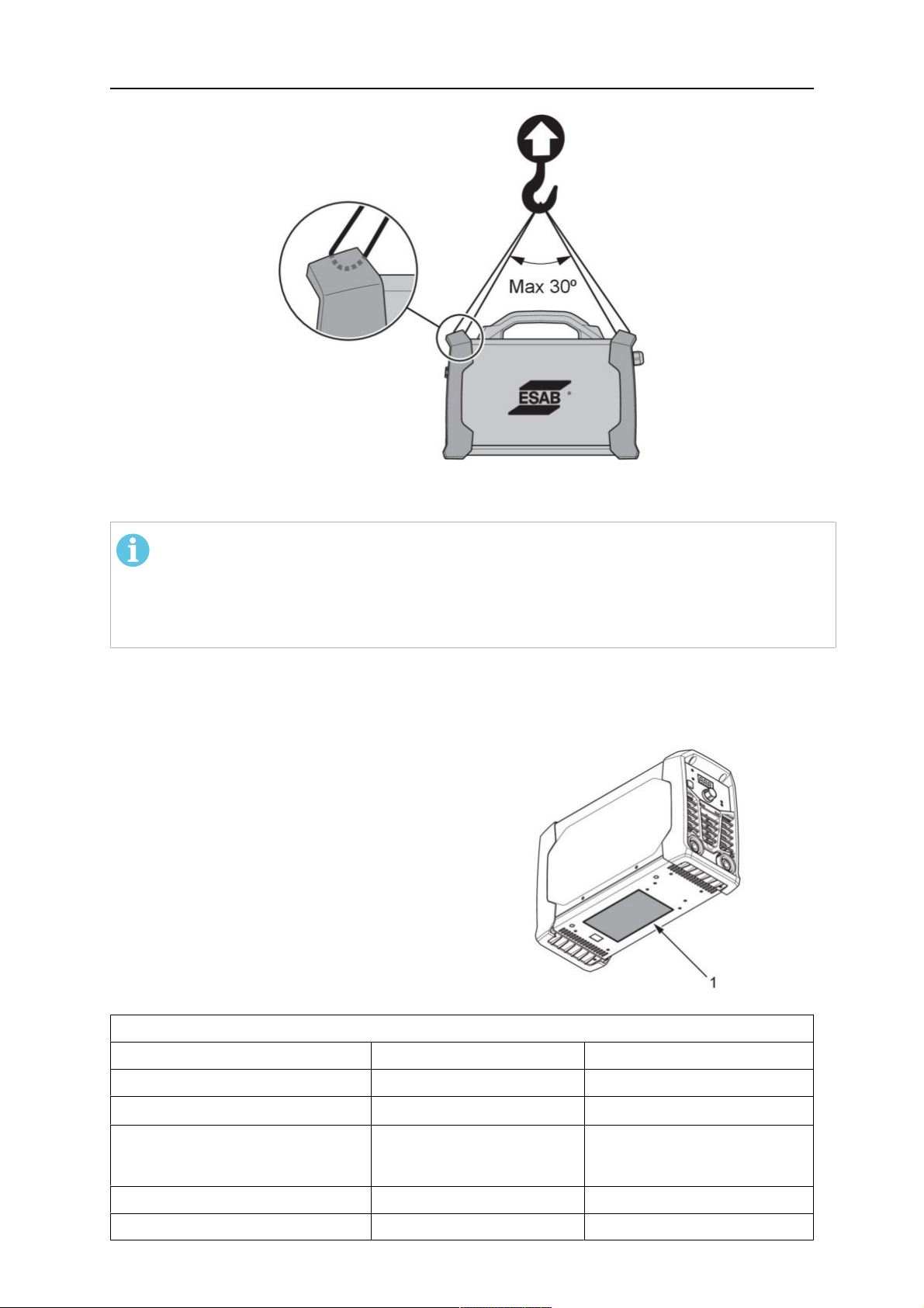
These units are equipped with a handle for carrying purposes.
WARNING!
Electric shock can kill. Do not touch live electrical parts. Disconnect input power
conductors from de-energized supply line before moving the welding power source.
WARNING!
Falling equipment can cause serious personal injury and equipment damage.
Lift the unit with handle on top of case.
0463 732 201
- 12 -
© ESAB AB 2022
Page 13
4 INSTALLATION
4.3 Mains supply
NOTE!
Rogue ES 150i and ES 180i do not comply with IEC 61000-3-12. If it is connected to
a public low voltage system, it is the responsibility of the installer or user of the
equipment to ensure, by consultation with the distribution network operator if
necessary, that the equipment may be connected.
The power source will automatically adjust to the supplied input voltage. Make sure that it is
protected by the correct fuse rating. A protective ground connection must be made, in
accordance with regulations.
Rating plate with supply connection
1.
data.
Recommended fuse sizes and minimum cable area for the Rogue ES 150i, ES 180i
Rogue ES 150i ES 180i
Supply voltage 230VAC 230VAC
Electrical cable area 2.5mm
2
2.5mm
2
Maximal current rating
I
MMA/Stick (SMAW)
max
30A 36A
I1eff MMA/Stick (SMAW) 15A 16A
Fuse anti-surge type D MCB 20A 25A
0463 732 201
- 13 -
© ESAB AB 2022
Page 14
4 INSTALLATION
Recommended fuse sizes and minimum cable area for the Rogue ES 150i, ES 180i
Supply voltage 230VAC
Maximum recommended extension cord
length 100m(328ft)
Minimum recommended extension cord size 4mm
2
NOTE!
Different variants of Rogue ES 150i, ES 180i are certified for different outlet
voltages. Always refer to the rating plate for the specification of the power source in
use.
NOTE!
Use the power source in accordance with the relevant national regulations.
Supply from power generators
The power source can be supplied from different types of generators. However, some
generators may not provide sufficient power for the welding power source to operate
correctly. Generators with Automatic Voltage Regulation (AVR) or with equivalent or better
type of regulation, with rated power 8 kW, are recommended.
0463 732 201
- 14 -
© ESAB AB 2022
Page 15
5 OPERATION
5 OPERATION
5.1 Overview
General safety regulations for handling the equipment can be found in the "SAFETY"
chapter of this manual. Read it through before you start using the equipment!
NOTE!
When moving the equipment use intended handle. Never pull the cables.
WARNING!
Electric shock! Do not touch the workpiece or the welding head during operation!
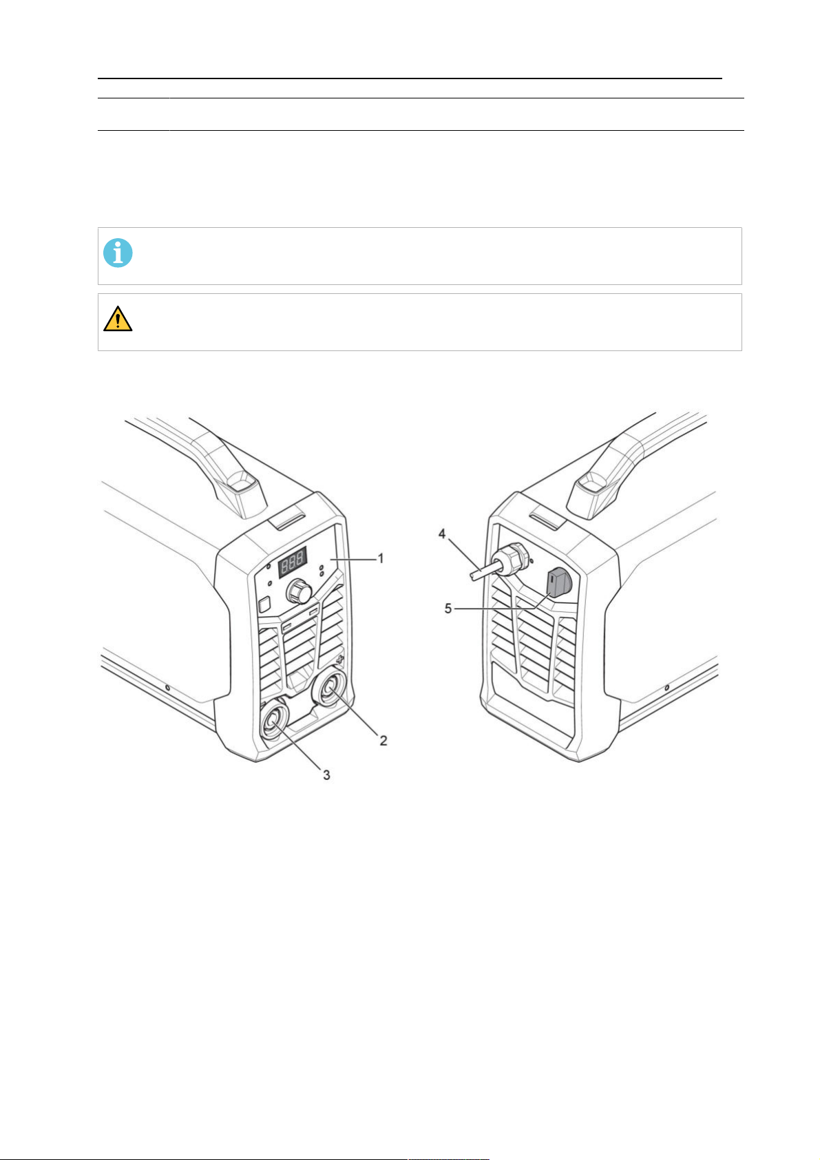
5.2 Connections and control devices
1. Setting Panel 4. Power Cable
2. Positive welding terminal 5. Mains power supply switch, I/O
3. Negative welding terminal
5.3 Connecting welding and return cables
The power source has two outputs, a positive welding terminal (+) and a negative welding
terminal (-), for connecting welding and return cables. The output to which the welding cable
is connected depends on the welding method or type of electrode used.
Connect the return cable to the other output on the power source. Secure the return cable’s
contact clamp to the workpiece, and make sure that there is a good contact between the
workpiece and the output for the return cable on the power source.
0463 732 201
- 15 -
© ESAB AB 2022
Page 16
5 OPERATION
• For TIG welding, the negative welding terminal (-) is used for the welding torch and the
positive welding terminal (+) is used for the return cable.
• For MMA welding, the welding cable can be connected to the positive welding terminal
(+) or negative welding terminal (-), depending on the type of electrode used. The
connection polarity is stated on the electrode packaging.
5.4 Turning the power on/off
Turn on the power by turning the switch to the “ON” (I) position.
Turn the unit off by turning the switch to the “O” position.
Whether the power supply is interrupted or the power source is switched off in the normal
manner, weld programs are stored so that they are available the next time the unit is started.
CAUTION!
Do not turn off the power source during welding (with load).
5.5 Fan control
The Rogue ES 150i, ES 180i is fitted with a fan as needed feature. Fan as needed
automatically switches the cooling fan off when it is not required. This has two main
advantages; (1) to minimize power consumption, and (2) to minimize the amount of
contaminants such as dust that are drawn into the power source.
Note that the fan will only operate when required for cooling purposes and will automatically
switch off when not required.
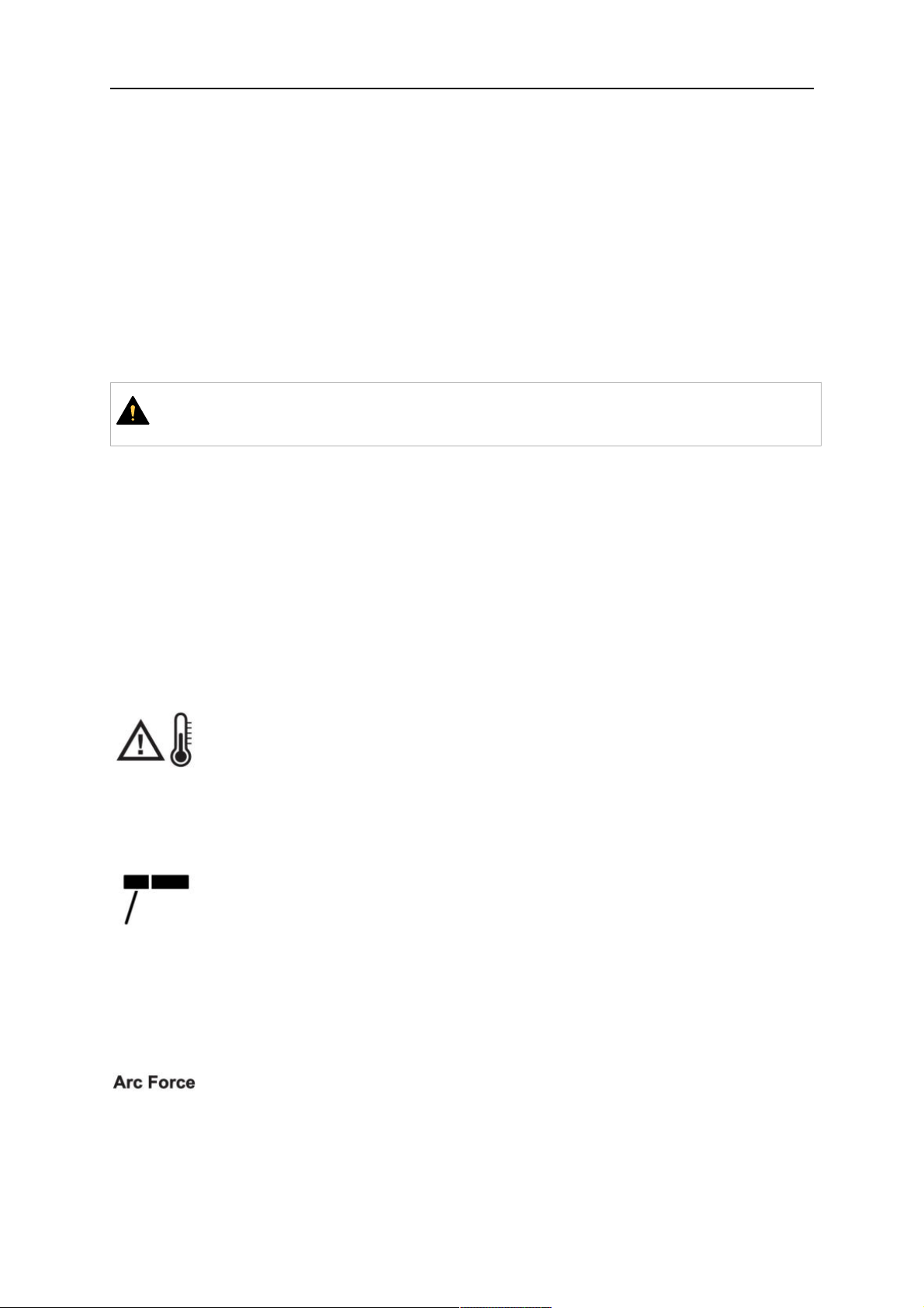
5.6 Thermal protection
The power source includes thermal protection against overheating. When
overheating occurs the welding is stopped and overheating indicator on the
panel will be lit and an error message shows in the display. The protection is
automatically reset when the temperature has been sufficiently reduced.
5.7 Functions and symbols
MMA welding
MMA welding may also be referred to as welding with coated electrodes. Striking
the arc melts the electrode, and its coating forms protective slag.
For MMA welding the power source shall be supplemented with:
• welding cable with electrode holder
• return cable with clamp
Arc force
0463 732 201
The arc force function determines how the current changes in response to
variations in arc length during welding. Use a low value of arc force to get a calm
arc with little spatter and use a high value to get a hot and digging arc.
Arc force only applies to MMA welding.
- 16 -
© ESAB AB 2022
Page 17
5 OPERATION
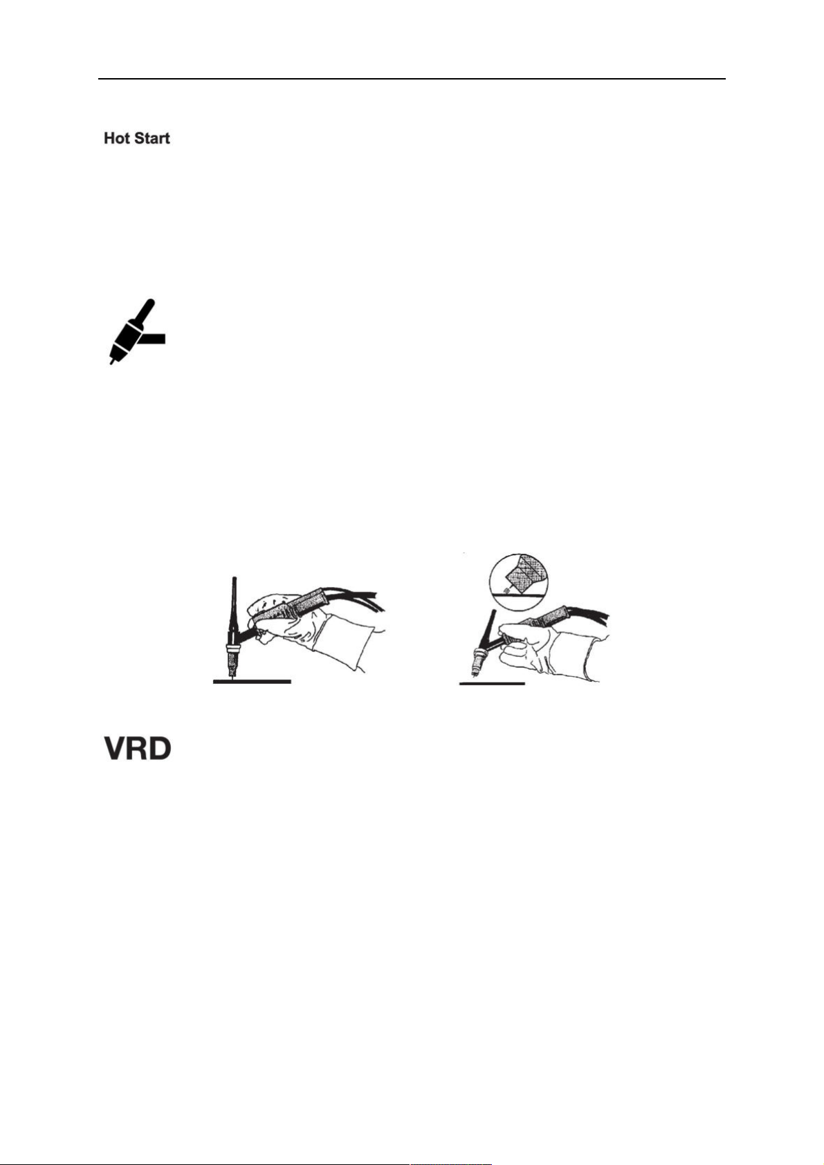
Hot start
The hot start function temporarily increases the current in the beginning of the
weld. Use this function to reduce risk of insufficient fusion and electrode sticking
and scratching. Hold process selection button and the display switches to "HS"
(Hot Start). Turn the current control knob, the display shows 0 or -1 to -10 or 1 to
10 (-10 to +10).
Press the process selection button again the display switches to AF (Arc Force).
Hot start only applies to MMA welding.
TIG welding
TIG welding melts the metal of the workpiece, using an arc struck from a
tungsten electrode that does not melt. The weld pool and electrode are
protected by shielding gas.
For TIG welding, the welding power source shall be supplemented with:
• a TIG torch with gas valve
• an argon gas cylinder
• an argon gas regulator
• tungsten electrode
This power source performs Live TIG start.
The tungsten electrode is placed against the workpiece. When lifted away from
workpiece the arc is struck at a limited current level.
Voltage Reduction Device (VRD)
The VRD function ensures that the open-circuit voltage does not exceed 35V
when welding is not being carried out. This is indicated by a lit VRD indicator on
the panel. Contact an authorised ESAB service technician to activate this
function.
0463 732 201
- 17 -
© ESAB AB 2022
Page 18
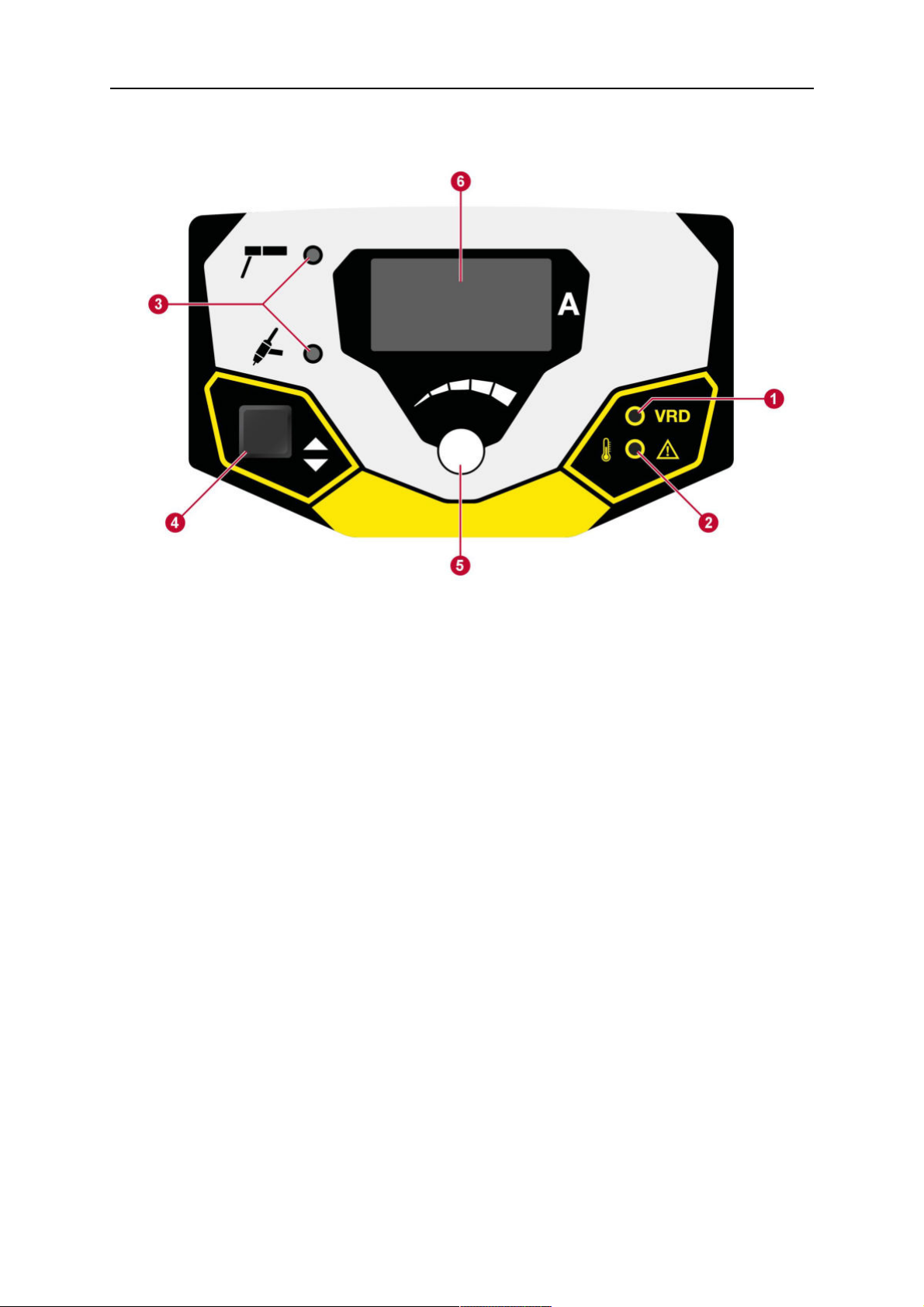
5 OPERATION
5.8 Setting panel
1. VRD function (reduced open-circuit
4. Select welding method, indicated by (3).
voltage) indicator.
2. Overheating indication. 5. Welding current control knob / HS (Hot
Start) / AF (Arc Force) control.
3. Indication of welding method: MMA or
6. Display, shows set or measured value.
Live TIG.
0463 732 201
- 18 -
© ESAB AB 2022
Page 19
6 MAINTENANCE
6 MAINTENANCE
WARNING!
The mains supply must be disconnected during cleaning and maintenance.
CAUTION!
Only persons with the appropriate electrical knowledge (authorised personnel) may
remove the safety plates.
CAUTION!
The product is covered by manufacturer's warranty. Any attempt to carry out repair
work by non-authorised service centers or personnel will invalidate the warranty.
NOTE!
Regular maintenance is important for safe and reliable operation.
NOTE!
Perform maintenance more often during severe dusty conditions.
Before each use - make sure that:
• Product and cables are not damaged,
• The torch is clean and not damaged.
6.1 Routine maintenance
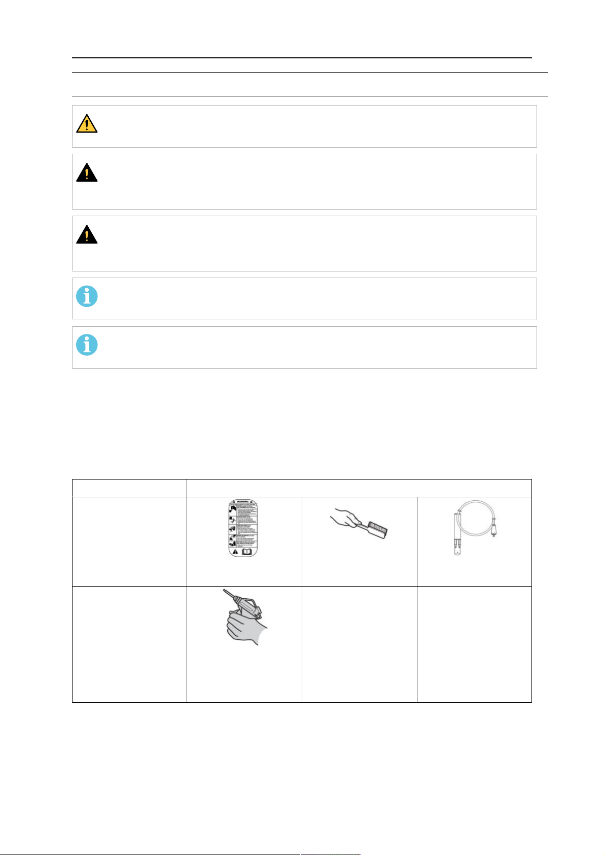
Maintenance schedule during normal conditions. Check equipment prior to every use.
Interval Area to maintain
Every 3 months
Clean or replace
unreadable labels.
Every 6 months
Clean inside
equipment. Use dry
compressed air with
reduced pressure.
Clean weld terminals. Check or replace weld
cables.
6.2 Cleaning instruction
To maintain the performance and increase the lifetime of the power source it is mandatory to
clean it regularly. How often depends on:
0463 732 201
- 19 -
© ESAB AB 2022
Page 20

6 MAINTENANCE
• the welding process
• the arc time
• the working environment
CAUTION!
Make sure that the cleaning procedure is done in a suitable prepared workspace.
CAUTION!
During cleaning, always wear recommended personal safety equipment, such as
ear plugs, safety glasses, masks, gloves and safety shoes.
1. Disconnect the power source from the mains supply.
2. Open the enclosure and use a vacuum cleaner to remove any accumulated dirt, metal
filings, slag and loose material. Keep the shunt and lead screw surfaces clean as
accumulated foreign material may reduce the welders output welding current.
0463 732 201
- 20 -
© ESAB AB 2022
Page 21

7 TROUBLESHOOTING
7 TROUBLESHOOTING
Perform these checks and inspections before sending for an authorised service technician.
• Check that the mains voltage is disconnected before starting any type of repair action.
Type of fault Corrective action
MMA welding problems Check the welding process is set for MMA.
Check that the welding and return cables are correctly
connected to the power source.
Make sure that the return clamp has good contact with the
workpiece.
Check that the correct electrodes and polarity are being used.
For polarity, check electrode packaging.
Check that the correct Welding current (A) is set.
Adjust Arc Force and Hot start.
TIG welding problems Check the welding process is set for Live TIG as necessary.
Check that the TIG torch and return cables are correctly
connected to the power source.
Make sure that the return clamp has good contact with the
workpiece.
Make sure that the TIG torch lead is connected to the negative
welding terminal.
Make sure that the correct shielding gas, gas flow, welding
current, filler rod placement, electrode diameter and welding
mode on power source is used.
Make sure that the gas valve on the TIG torch is ON.
No arc Check that the electrical power supply switch is turned on.
Check that the display is on to verify that the power source has
power.
Check that the setting panel is displaying correct values.
Check that the welding and return cables are correctly
connected.
Check the electrical power supply fuses.
Welding current is
interrupted during welding
Check whether the Over Temperature LED (Thermal Protection)
on the setting panel is on.
Continue with Troubleshooting “No Arc”.
The thermal protection
trips frequently
Make sure that the recommended duty cycle for the weld
current has not been exceeded.
0463 732 201
Refer to power source “Duty cycle” section in "TECHNICAL
DATA", page10.
Make sure that the air inlets or outlets are not clogged.
Clean the inside of the machine using routine maintenance
methods.
- 21 -
© ESAB AB 2022
Page 22

8 ORDERING SPARE PARTS
8 ORDERING SPARE PARTS
CAUTION!
Repair and electrical work should be performed by an authorised ESAB service
technician. Use only ESAB original spare and wear parts.
The Rogue ES 150i, ES 180i is designed and tested in accordance with the international
and European standards EN60974-1 and EN60974-10. On completion of service or repair
work, it is the responsibility of the person(s) performing the work to ensure that the product
still complies with the requirements of the above standards.
Spare parts and wear parts can be ordered through your nearest ESAB dealer, see
esab.com. When ordering, please state product type, serial number, designation and spare
part number in accordance with the spare parts list. This facilitates dispatch and ensures
correct delivery.
0463 732 201
- 22 -
© ESAB AB 2022
Page 23
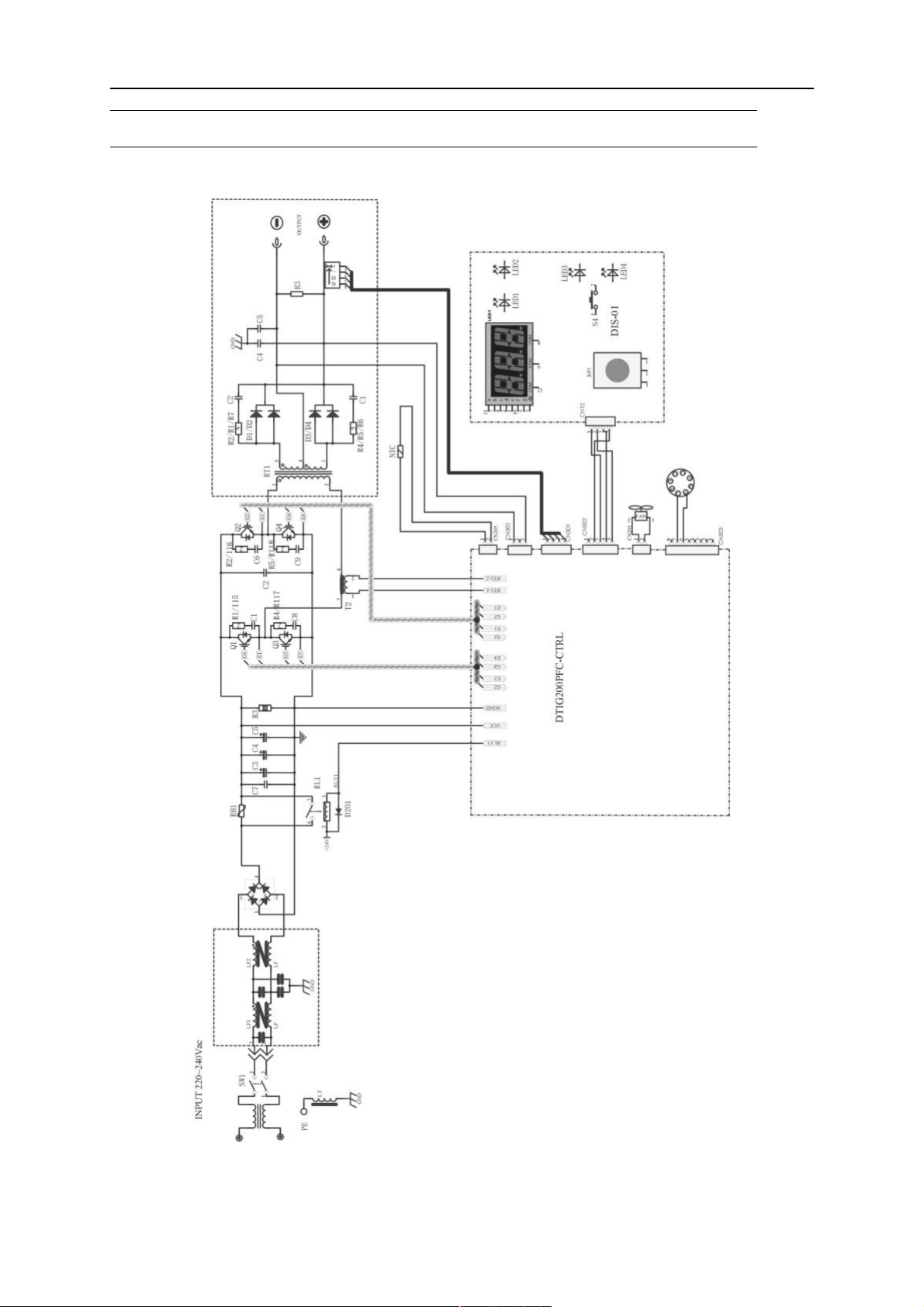
DIAGRAM
DIAGRAM
For serial number HA017-xxxx-xxxx, HA18-xxxx-xxxx
0463 732 201
- 23 -
© ESAB AB 2022
Page 24
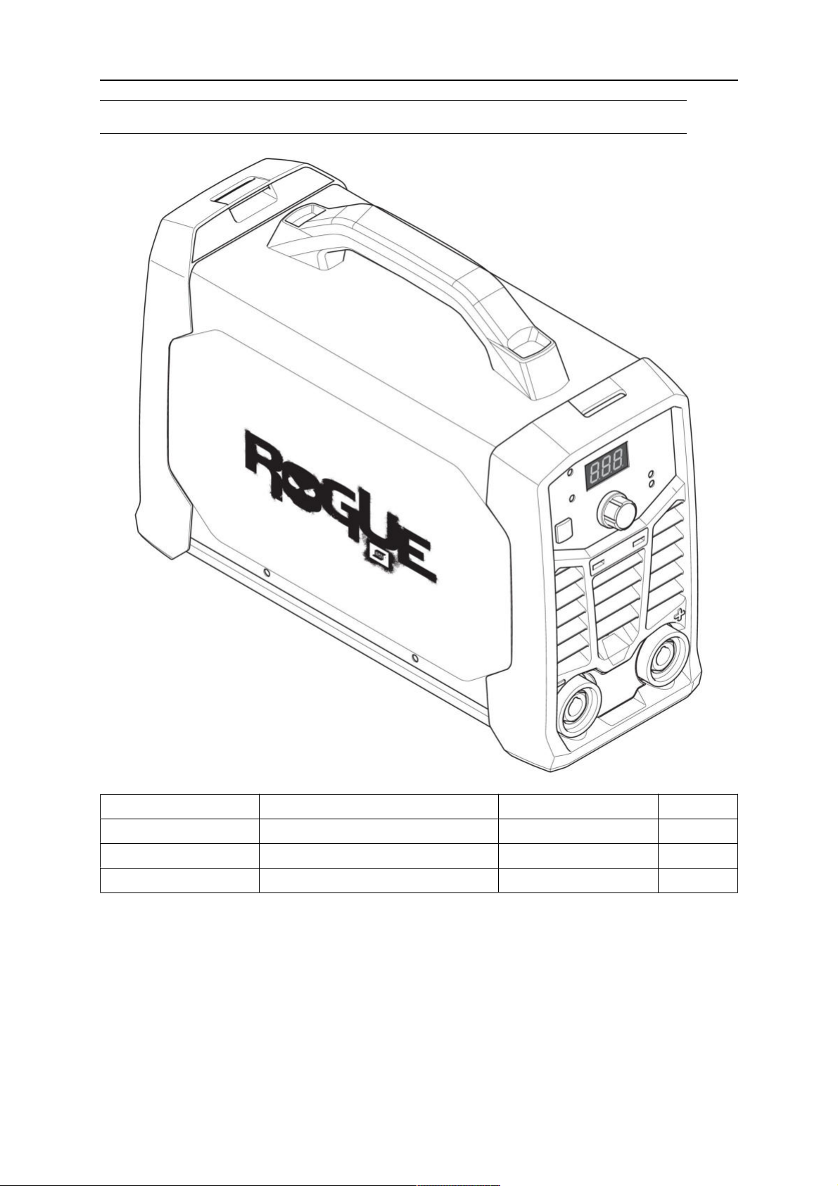
ORDERING NUMBERS
ORDERING NUMBERS
Ordering number Denomination Type Notes
0700 500 076 Power source ES 150i
0700 500 077 Power source ES 180i
0463 732 101 Instruction manual
Technical documentation is available on the Internet at: www.esab.com
The three last digits in the document number of the manual show the version of the manual.
Therefore they are replaced with * here. Make sure to use a manual with a serial number or
software version that corresponds with the product, see the front page of the manual.
0463 732 201
- 24 -
© ESAB AB 2022
Page 25
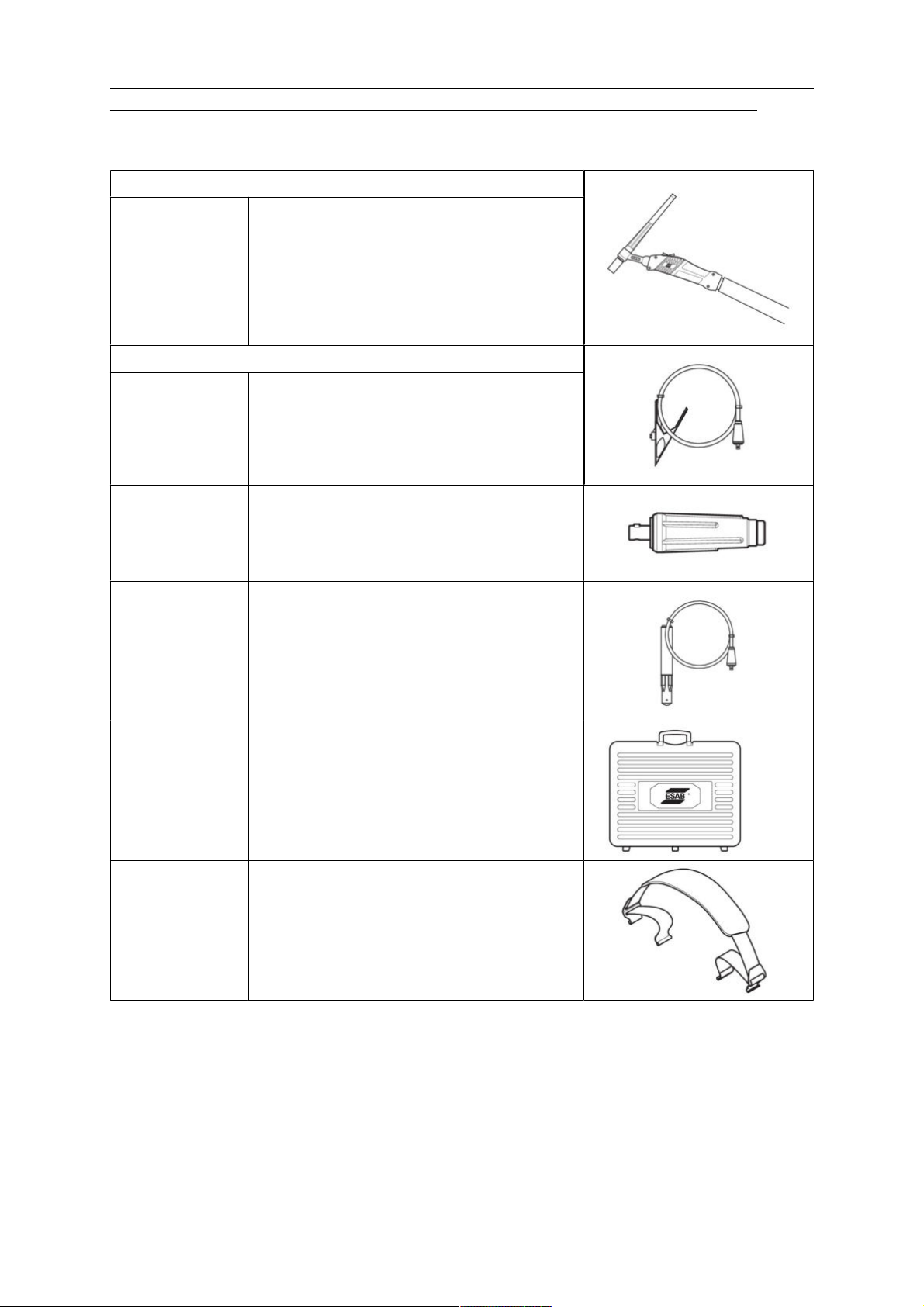
ACCESSORIES
ACCESSORIES
TIG torches
0700 025 514
0700 025 522
SR-B 17V, OKC 50, 4m
SR-B 26V, OKC 50, 4m
Return cable kits
0700 006 889
0700 006 903
Return cable kit, OKC 50, 5m
Return cable kit, OKC 50, 3m
0160 360 881 OKC 50 male cable connector, 1/0-4/0
cable (50mm²) EU
0700 006 900 Electrode holder Handy 200A with25mm²,
3m, OKC 50
0700 500 085 Rogue plastic case (Toolbox)
0700 500 086 Shoulder strap
0463 732 201
- 25 -
© ESAB AB 2022
Page 26

ESAB AB, Lindholmsallén 9, Box 8004, 402 77 Gothenburg, Sweden, Phone +46 (0) 31 50 90 00
http://manuals.esab.com
For contact information visit esab.com
 Loading...