

ESAB EMP 255ic, EMP 320ic Instruction Manual

EMP 255ic & EMP 320ic
Instruction manual
0463 605 001 GB 20181217
Valid for: serial no. 730-xxx-xxxx, 735-xxx-xxxx

TABLE OF CONTENTS
1
SAFETY ....................................................................................................... 5
1.1 Meaning of symbols ............................................................................... 5
1.2 Safety precautions ................................................................................. 5
2
INTRODUCTION.......................................................................................... 8
2.1 Overview ................................................................................................. 8
2.2 Equipment ............................................................................................... 8
3
TECHNICAL DATA ...................................................................................... 9
4
INSTALLATION............................................................................................ 11
4.1 Location................................................................................................... 11
4.2 Lifting instructions ................................................................................. 11
4.3 Mains supply........................................................................................... 12
5
OPERATION ................................................................................................ 14
5.1 User connections and controls............................................................. 15
5.2 Connection of welding and return cables ............................................ 16
5.2.1 For MIG/MMA process ........................................................................ 16
5.2.2 For TIG process.................................................................................... 17
5.3 Polarity change....................................................................................... 17
5.4 Shielding gas .......................................................................................... 17
5.5 Volt-ampere curves ................................................................................ 17
5.5.1 SMAW (Stick) 400 V............................................................................. 18
5.5.2 GMAW (MIG) 400 V ............................................................................. 18
5.5.3 GTAW (TIG) 400 V ............................................................................... 19
5.6 Duty cycle ............................................................................................... 19
5.7 Removing/installing bobbin .................................................................. 20
5.8 Removing/installing wire ....................................................................... 21
5.8.1 Removing wire...................................................................................... 23
5.8.2 Installing wire........................................................................................ 25
5.9 Welding with aluminum wire ................................................................. 25
5.10 Setting wire-feed pressure .................................................................... 26
5.11 Removing/installing wire-feed rollers .................................................. 27
5.11.1 Removing wire-feed rollers................................................................... 27
5.11.2 Installing wire-feed rollers..................................................................... 29
5.12 Removing/installing/adjusting wire-guides ......................................... 30
5.12.1 Output wire-guide removal/installation ................................................. 32
5.12.2 Center wire-guide removal/installation ................................................. 33
5.12.3 Adjusting wire guides ........................................................................... 33
5.13 Overheating protection .......................................................................... 34
5.14 Lift-TIG welding ...................................................................................... 34
6
CONTROL PANEL....................................................................................... 36
6.1 How to navigate ...................................................................................... 36
6.2 Main menu............................................................................................... 36
0463 605 001 © ESAB AB 2018

TABLE OF CONTENTS
6.3 sMIG mode: Basic .................................................................................. 36
6.4 sMIG mode: Advanced........................................................................... 37
6.5 Manual MIG mode: Basic ....................................................................... 37
6.6 Manual MIG mode: Advanced ............................................................... 37
6.7 Flux cored wire mode: Basic................................................................. 37
6.8 Flux cored wire mode: Advanced ......................................................... 38
6.9 MMA mode: Basic................................................................................... 38
6.10 MMA mode: Advanced ........................................................................... 38
6.11 Lift-TIG mode: Basic .............................................................................. 39
6.12 Lift-TIG mode: Advanced....................................................................... 39
6.13 Settings ................................................................................................... 39
6.14 User manual information ....................................................................... 39
6.15 Icon reference guide .............................................................................. 40
7
MAINTENANCE........................................................................................... 43
7.1 Routine maintenance ............................................................................. 43
7.2 Wire-feeder assembly maintenance ..................................................... 43
7.2.1 Wire-feeder assembly cleaning ............................................................ 44
7.3 EMP-unit power side maintenance ....................................................... 47
7.4 Torch liner maintenance ........................................................................ 47
7.4.1 Torch liner cleaning .............................................................................. 47
8
TROUBLESHOOTING ................................................................................. 48
8.1 Preliminary checks................................................................................. 48
8.2 User interface (UI) software displayed error codes ............................ 49
9
ORDERING SPARE PARTS ........................................................................ 51
DIAGRAM ............................................................................................................ 52
ORDERING NUMBERS....................................................................................... 54
WEAR PARTS...................................................................................................... 55
ACCESSORIES ................................................................................................... 56
REPLACEMENT PARTS ..................................................................................... 57
ROLLER & WIRE-GUIDE SELECTION .............................................................. 58
Rights reserved to alter specifications without notice.
0463 605 001 © ESAB AB 2018
1 SAFETY
1 SAFETY
1.1 Meaning of symbols
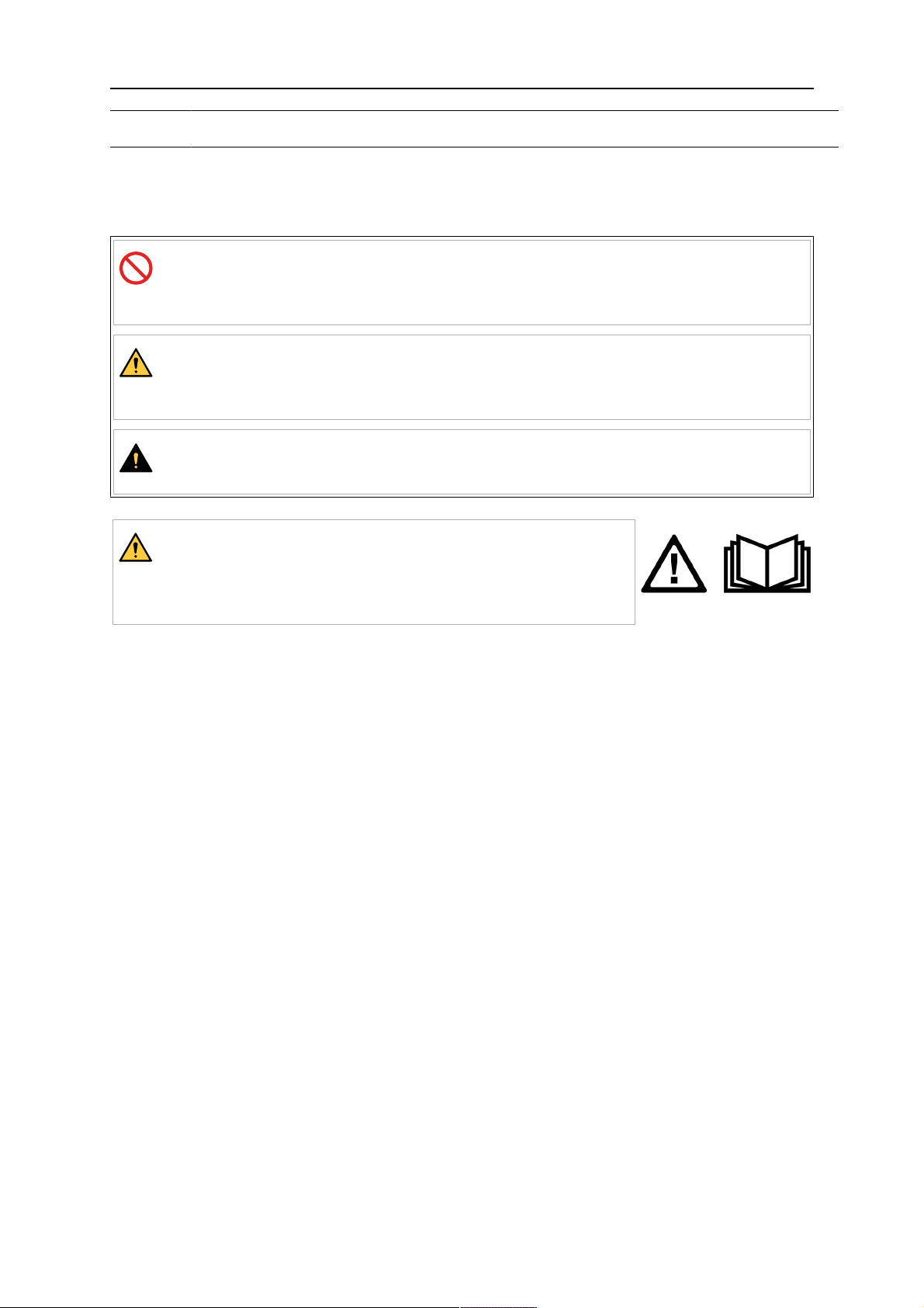
As used throughout this manual: Means Attention! Be Alert!
DANGER!
Means immediate hazards which, if not avoided, will result in
immediate, serious personal injury or loss of life.
WARNING!
Means potential hazards which could result in personal injury or loss
of life.
CAUTION!
Means hazards which could result in minor personal injury.
WARNING!
Before use, read and understand the instruction manual
and follow all labels, employer´s safety practices and
Safety Data Sheets (SDSs).
1.2 Safety precautions
Users of ESAB equipment have the ultimate responsibility for ensuring that anyone who
works on or near the equipment observes all the relevant safety precautions. Safety
precautions must meet the requirements that apply to this type of equipment. The following
recommendations should be observed in addition to the standard regulations that apply to
the workplace.
All work must be carried out by trained personnel well-acquainted with the operation of the
equipment. Incorrect operation of the equipment may lead to hazardous situations which can
result in injury to the operator and damage to the equipment.
1. Anyone who uses the equipment must be familiar with:
○ its operation
○ location of emergency stops
○ its function
○ relevant safety precautions
○ welding and cutting or other applicable operation of the equipment
2. The operator must ensure that:
○ no unauthorised person is stationed within the working area of the equipment
when it is started up
○ no-one is unprotected when the arc is struck or work is started with the
equipment
3. The workplace must:
○ be suitable for the purpose
○ be free from drafts
0463 605 001
- 5 -
© ESAB AB 2018

1 SAFETY
4. Personal safety equipment:
○ Always wear recommended personal safety equipment, such as safety glasses,
flame-proof clothing, safety gloves
○ Do not wear loose-fitting items, such as scarves, bracelets, rings, etc., which
could become trapped or cause burns
5. General precautions:
○ Make sure the return cable is connected securely
○ Work on high voltage equipment may only be carried out by a qualified
electrician
○ Appropriate fire extinguishing equipment must be clearly marked and close at
hand
○ Lubrication and maintenance must not be carried out on the equipment during
operation
WARNING!
Arc welding and cutting can be injurious to yourself and others. Take precautions
when welding and cutting.
ELECTRIC SHOCK - Can kill
• Install and ground the unit in accordance with instruction manual.
• Do not touch live electrical parts or electrodes with bare skin, wet gloves or
wet clothing.
• Insulate yourself from work and ground.
• Ensure your working position is safe
ELECTRIC AND MAGNETIC FIELDS - Can be dangerous to health
• Welders having pacemakers should consult their physician before welding.
EMF may interfere with some pacemakers.
• Exposure to EMF may have other health effects which are unknown.
• Welders should use the following procedures to minimize exposure to
EMF:
○ Route the electrode and work cables together on the same side of
your body. Secure them with tape when possible. Do not place your
body between the torch and work cables. Never coil the torch or work
cable around your body. Keep welding power source and cables as
far away from your body as possible.
○ Connect the work cable to the workpiece as close as possible to the
area being welded.
FUMES AND GASES - Can be dangerous to health
• Keep your head out of the fumes.
• Use ventilation, extraction at the arc, or both, to take fumes and gases
away from your breathing zone and the general area.
ARC RAYS - Can injure eyes and burn skin
• Protect your eyes and body. Use the correct welding screen and filter lens
and wear protective clothing.
• Protect bystanders with suitable screens or curtains.
0463 605 001
NOISE - Excessive noise can damage hearing
Protect your ears. Use earmuffs or other hearing protection.
- 6 -
© ESAB AB 2018

1 SAFETY
MOVING PARTS - Can cause injuries
• Keep all doors, panels and covers closed and securely in place. Have only
qualified people remove covers for maintenance and troubleshooting as
necessary. Reinstall panels or covers and close doors when service is
finished and before starting engine.
• Stop engine before installing or connecting unit.
• Keep hands, hair, loose clothing and tools away from moving parts.
FIRE HAZARD
• Sparks (spatter) can cause fire. Make sure that there are no inflammable
materials nearby.
• Do not use on closed containers.
MALFUNCTION - Call for expert assistance in the event of malfunction.
PROTECT YOURSELF AND OTHERS!
CAUTION!
This product is solely intended for arc welding.
WARNING!
Do not use the power source for thawing frozen pipes.
CAUTION!
Class A equipment is not intended for use in residential
locations where the electrical power is provided by the
public low-voltage supply system. There may be
potential difficulties in ensuring electromagnetic
compatibility of class A equipment in those locations,
due to conducted as well as radiated disturbances.
NOTE!
Dispose of electronic equipment at the recycling
facility!
In observance of European Directive 2012/19/EC on
Waste Electrical and Electronic Equipment and its
implementation in accordance with national law,
electrical and/or electronic equipment that has reached
the end of its life must be disposed of at a recycling
facility.
As the person responsible for the equipment, it is your
responsibility to obtain information on approved
collection stations.
For further information contact the nearest ESAB dealer.
ESAB has an assortment of welding accessories and personal protection equipment
for purchase. For ordering information contact your local ESAB dealer or visit us on
our website.
0463 605 001
- 7 -
© ESAB AB 2018

2 INTRODUCTION
2 INTRODUCTION
2.1 Overview
The ESAB, EMP 255ic and EMP 320ic product family is a new generation of multi-process
(MIG, TIG, MMA) welding power sources designed to match the needs of the user across a
variety of welding applications.
The EMP features a 11 cm (4.3 in.) color TFT (Thin Film Transistor) user interface (UI)
display which provides quick and easy selection of weld process and parameters, suitable for
both newly trained and intermediate-level users. For more advanced users, any number of
functions could be introduced and customized to give maximum flexibility.
ESAB accessories for the product can be found in the "ACCESSORIES" chapter of
this manual.
2.2 Equipment
The power source is supplied with:
• USB stick including instruction manual
• Safety manual
• 3 m (9.8 ft) mains cable with CEE 16A plug
• Gas hose for with Quick Connector
• Return cable with ground clamp, 4.5 m, 300A
• Guide tubes: 0.8 mm (0.030 in) – 1.2 mm (0.045 in)
• Drive rolls
○ 1.0 mm (0.040 in)/1.2 mm (0.045 in)
○ 0.8 mm (0.030 in)/1.0 mm (0.040 in)
• Thickness gauge tool
0463 605 001
- 8 -
© ESAB AB 2018

3 TECHNICAL DATA
3 TECHNICAL DATA
EMP 320ic (0700 300 991) EMP 255ic (0700 300 992)
Mains voltage 400 V ±10%, 3~ 50/60 Hz 400 V ±10%, 3~ 50/60 Hz
Primary current
I
MMA / I
max
I
TIG / I
max
I
MIG / I
max
No-load power demand when in the energy-saving mode
Uin400 V 68 W
Setting range
MMA 16 A / 20 V - 300 A / 32 V 16 A / 20 V - 255 A / 30 V
TIG 5 A / 10 V - 320 A / 23 V 5 A / 10 V - 255 A / 20 V
MIG 15 A / 15 V – 320 A / 34 V 15 A / 15 V – 300 A / 34 V
Permissible load at MMA
MMA 18.0 A / 11.4 13.0 A / 9.4 A
eff
TIG 16.0 A / 10.1 15.0 A / 6.3 A
eff
MIG 18.0 A / 11.4 17.0 A / 8.5 A
eff
40% duty cycle 300 A / 32.0 V 255 A / 30.0 V
60% duty cycle 255 A / 30.0 V 170 A / 27.0 V
100% duty cycle 180 A / 27.0 V 130 A / 25.0 V
Permissible load at TIG
40% duty cycle 320 A / 23.0 V 255 A / 30.0 V
60% duty cycle 265 A / 21.0 V 215 A / 19.0 V
100% duty cycle 220 A / 19.0 V 170 A / 17.0 V
Permissible load at MIG
40% duty cycle 320 A / 23.0 V 255 A / 27.0 V
60% duty cycle 265 A / 27.0 V 200 A / 24.0 V
100% duty cycle 200 A / 24.0 V 160 A / 22.0 V
Efficiency 86% 86%
Power factor 0.87 0.87
Open-circuit voltage U
0
68 V 68 V
max
Open-circuit voltage U
0
35 V 35 V
max with VRD activated
Wire feed speed 1.3 – 20 m/min (50 – 800 in./min)
Wire diameter
Mild steel solid wire 0.8 – 1.2 mm (0.030 – 0.045 in.)
Stainless steel solid wire 0.8 – 1.2 mm (0.030 – 0.045 in.)
Flux-cored wire 0.8 – 1.6 mm (0.030 - 0.045 in.)
Aluminum 0.8 – 1.2 mm (0.030 – 0.045 in.)
Operating temperature -10 to +40 °C (+14 to +104 °F)
Transportation temperature -20 to +55 °C (-4 to +131 °F)
Bobbin size 100 – 300 mm (4 – 12 in.)
0463 605 001
- 9 -
© ESAB AB 2018

3 TECHNICAL DATA
Dimensions l × w × h 686 × 292 × 495 mm (27.0 × 11.5 × 19.5 in.)
Weight 31.75 kg (70.0 lb)
Enclosure class IP23
Duty cycle
The duty cycle refers to the time as a percentage of a ten-minute period that you can weld or
cut at a certain load without overloading. The duty cycle is valid for 40°C(104°F).
Enclosure class
The IP code indicates the enclosure class, i.e. the degree of protection against penetration
by solid objects or water.
Equipment marked IP 23S is intended for indoor and outdoor use; however, should not be
operated in precipitation.
Application class
The symbol indicates that the power source is designed for use in areas with increased
electrical hazard.
0463 605 001
- 10 -
© ESAB AB 2018
4 INSTALLATION
4 INSTALLATION
The installation must be carried out by a professional.
CAUTION!
This product is intended for industrial use. In a domestic environment this product may
cause radio interference. It is the user's responsibility to take adequate precautions.
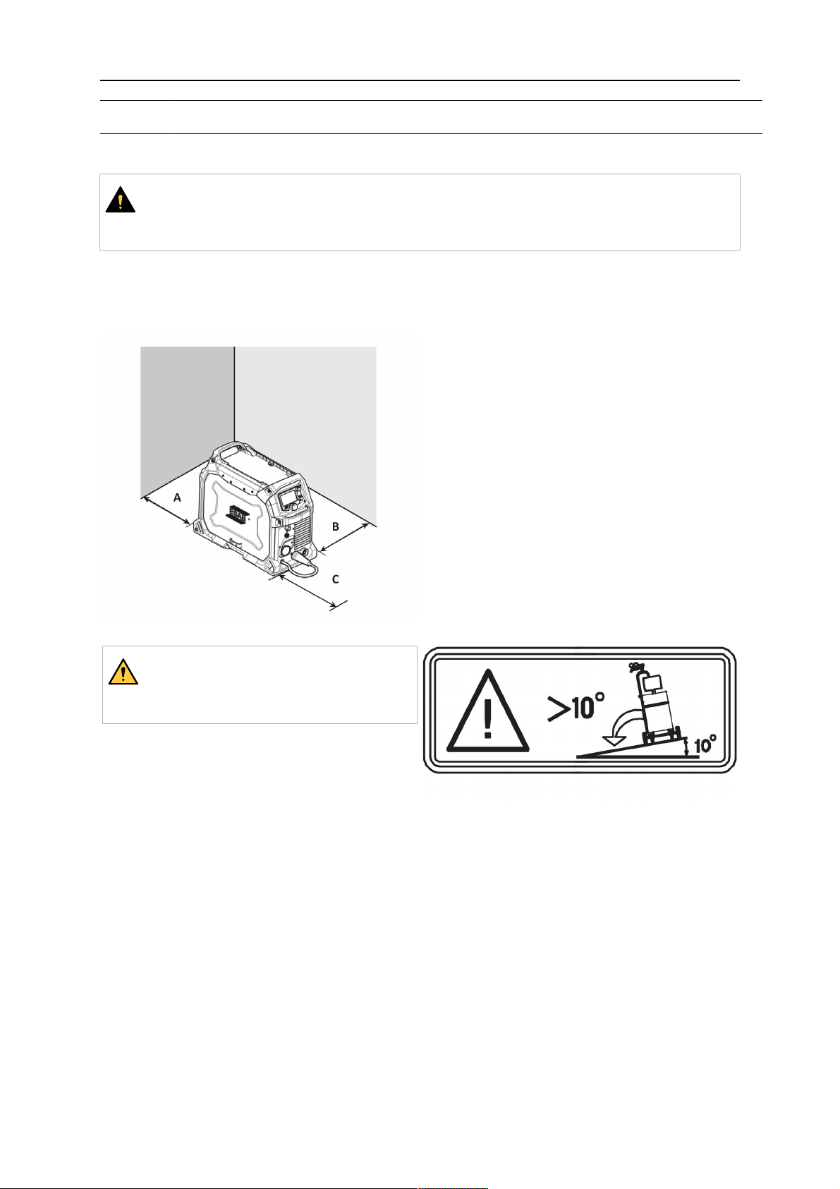
4.1 Location
Position the power source so that its cooling air inlets and outlets are not obstructed.
A. 152 mm (6 in.)
B. 100 mm (4 in.)
C. 152 mm (6 in.)
WARNING!
Secure the equipment - particularly
if the ground is uneven or sloping.
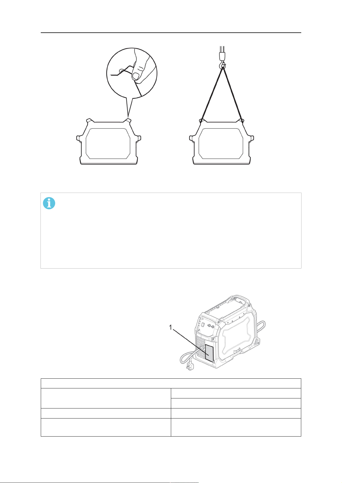
4.2 Lifting instructions
The power source can be lifted using any of the handles. Mechanical lifting must be done
with both outer handles.
0463 605 001
- 11 -
© ESAB AB 2018
4 INSTALLATION
4.3 Mains supply
NOTE!
Mains supply requirements
This equipment complies with IEC 61000-3-12 provided that the short-circuit power is
greater than or equal to S
at the interface point between the user's supply and
scmin
the public system. It is the responsibility of the installer or user of the equipment to
ensure, by consultation with the distribution network operator if necessary, that the
equipment is connected only to a supply with a short-circuit power greater than or
equal to S
. Refer to the technical data in the TECHNICAL DATA chapter.
scmin
The power source is delivered with a 4×2.5 mm2 mains cable and 16 A mains plug which in
combination can handle the rated data given for 3-phase 380–415 V mains supply.
1. Rating plate with supply
connection data
Recommended fuse sizes and minimum cable area
Mains voltage 3~ 50/60 Hz
400 V ±10%
Input current at maximum output 18 A
Maximum recommended fuse1)or circuit
16 A
breaker rating
0463 605 001
- 12 -
© ESAB AB 2018

4 INSTALLATION
Mains cable area
Maximum recommended extension cord
4 x 2.5 mm2(13 AWG)
15 m (50ft)
length
1)
Time delay fuse.
Supply from power generators
The power source can be supplied from different types of generators. However, some
generators may not provide sufficient power for the welding power source to operate
correctly. Generators with Automatic Voltage Regulation (AVR) or with equivalent or better
type of regulation, with rated power 15 kW 3-phase, are recommended.
0463 605 001
- 13 -
© ESAB AB 2018
5 OPERATION
5 OPERATION
General safety regulations for handling the equipment can be found in the chapter
"Safety". Read it through before you start the equipment.
NOTE!
When moving the equipment use intended handle. Never pull the cables.
WARNING!
Rotating parts can cause injury, take great care.
WARNING!
Electric shock! Do not touch the workpiece or the welding head during operation!
WARNING!
Assure that the side covers are closed during operation.
WARNING!
Tighten the bobbin bolt to prevent it from sliding off the hub.
0463 605 001
- 14 -
© ESAB AB 2018
5 OPERATION
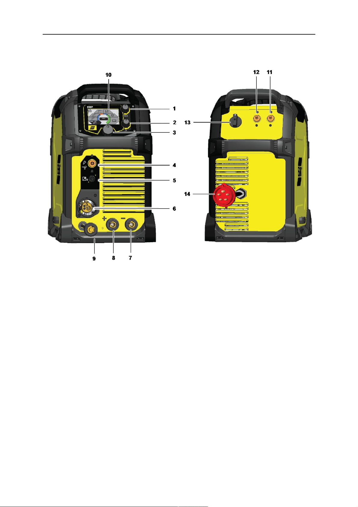
5.1 User connections and controls
Figure 1. Front & rear views: Model EMP 255ic & EMP 320ic
1. Knob for current or wire feed speed
8. Positive output [+]
selection
2. Knob for voltage selection 9. Polarity changeover cable
3. Main knob for navigation and parameter
10. Display
selection
4. Gas outlet for TIG & spool torch 11. Gas inlet for MIG/MAG
5. Torch/remote control connection 12. Gas inlet for TIG
6. Torch connection and MIG/MAG gas
13. Main power switch ON/OFF
outlet
7. Negative output [-] 14. Main power cable
0463 605 001
- 15 -
© ESAB AB 2018

5 OPERATION
1. Upper control knob:
(a)Setcurrentoutputvalue
3. Menu navigation:
Rotateandpushtoselectmenu option.
(b)Setwirefeedspeed
2. Lower control knob:
(a)MIGvoltageselection
(b)SMIGvoltagetrim
(c)MMAmode:ArcON/OFF
NOTE!
Lower control knob in MMA Mode turns output power ON/OFF. When output power is
ON, background of display turns orange (see "CONTROL PANEL" chapter).
5.2 Connection of welding and return cables
The power source has two outputs for connecting welding and return cables: a negative [-]
terminal (7) and a positive [+] terminal (8).
5.2.1 For MIG/MMA process
For MIG/MMA process, the output to which the welding cable is connected depends on the
type of electrode. Refer to electrode packaging for information relating to the correct
electrode polarity. Connect the return cable to the remaining welding terminal (9) on the
power source.
Secure the return cable's contact clamp to the work piece and ensure that there is good
electrical contact.
NOTE!
MIG welding guidance chart:
The backside of the door on the bobbin side displays a MIG welding guidance chart
for initial selection of welding controls. This is intended as a guide for setting
parameters on this equipment.
0463 605 001
- 16 -
© ESAB AB 2018

5 OPERATION
5.2.2 For TIG process
For TIG process (requires optional TIG accessories: see "ACCESSORIES" chapter), connect
the TIG torch power cable to the negative [-] terminal (7). Connect the gas inlet nut on the
TIG torch to the gas outlet connector (4) located on the front of the power source. Connect
the gas inlet nut (12), on rear panel, to a regulated shielding gas supply. Connect the work
return lead to the return-cable terminal (9). Connect the torch connector to the Euro-torch
connection (6).
5.3 Polarity change
The unit’s power source is delivered with the polarity changeover cable connected to the
positive terminal. Some wires, e.g. self-shielded cored wires, are recommended to be welded
with negative polarity. Negative polarity means that the polarity changeover cable is
connected to the negative terminal and the return cable remains as the connection for the
torch return-cable.
Check the recommended polarity for the welding wire you want to use. Refer to
electrode packaging for information relating to the correct electrode polarity. The
polarity can be changed by moving the polarity changeover cable to suit the
applicable welding process.
5.4 Shielding gas
The choice of suitable shielding gas depends on the material and weld process. Typically, in
MIG/MAG process, mild steel is welded with mixed gas (Ar + CO2) or 100% carbon dioxide
(CO2). Stainless steel can be welded with mixed gas (Ar + CO2) or trimix (He + Ar + CO2).
Aluminum and silicon bronze use pure argon gas (Ar). In the sMIG mode (see "sMIG mode"
section in the "CONTROL PANEL" chapter), the optimal welding arc with the gas used will be
automatically set. In TIG process 100% argon is typically used.
5.5 Volt-ampere curves
The curves below show the maximum voltage and amperage output capabilities of the power
source for three common welding process settings. Other settings result in curves that fall
between these curves.
A= Welding current (AMPS), V = Output voltage
0463 605 001
- 17 -
© ESAB AB 2018

5 OPERATION
5.5.1 SMAW (Stick) 400 V
V = Output voltage
A = Welding current (Amps)
5.5.2 GMAW (MIG) 400 V
V = Output voltage
A = Welding current (Amps)
0463 605 001
- 18 -
© ESAB AB 2018
 Loading...