


104
DTB 250
Инструкция по эксплуатации
Instruction manual
Valid for Serial NO 548 XXX--XXXX0456 267 027 99.03.08

Русский 3...............................................
ENGLISH 11..............................................
Rights reserved to alter specifications without notice.
Оставляемза собой право изменять спецификацию без предупреждения.
-- 2 --

Русский
1 ТЕХНИКА БЕЗОПАСНОСТИ 4........................................
2 ВВЕДЕНИЕ 4.......................................................
2.1 ТЕХНИЧЕСКИЕ ДАННЫЕ 5.................................................
3УСТАНОВКА 6.......................................................
3.1 Подсоединение к электросети 6............................................
3.2 Инструкция по монтажу 6..................................................
4РАБОТА 7...........................................................
4.1 Сварка ТIG на постоянном токе 9..........................................
4.2 Сварка ТIG на переменном токе 9..........................................
4.3 Сварка ММА на постоянном или переменном токе 10........................
5 ОБСЛУЖИВАНИЕ 10.................................................
5.1 Общее 10..................................................................
6 ЗАКАЗ ЗАПАСНЫХ ЧАСТЕЙ 10.......................................
СХЕМА 20..............................................................
ДОПОЛНИТЕЛЬНЫЕ ПРИНАДЛЕЖНОСТИ 21...........................
СПИСОК ЗАПАСНЫХ ЧАСТЕЙ 23........................................
TOCr
-- 3 --

1 ТЕХНИКА БЕЗОПАСНОСТИ
ПРЕДУПРЕЖДЕНИЕ !
ДУГОВАЯ СВАРКА И РЕЗКА МОГУТ ПРИЧИНИТЬ ВРЕД ВАМ И ОКРУЖАЮЩИМ. ПРИМИТЕ
НЕОБХОДИМЫЕ МЕРЫ БЕЗОПАСНОСТИ ПРИ ПРОВЕДЕНИИ СВАРОЧНЫХ РАБОТ.
ОЗНАКОМЬТЕСЬ С ТЕХНИКОЙ БЕЗОПАСНОСТИ, РАЗРАБОТАННОЙ НА ВАjЕМ ПРЕДПРИЯТИИ.
ПОР АЖЕНИЕ ЭЛЕКТРИЧЕСКИМ ТОК ОМ ОПАСНО ДЛЯ ЖИЗНИ !
S Установите и заземлите сварочный аппарат в соответствии с применяемыми стандартами.
S Не касайтесь оголенных электрических частей или электродов голыми руками, мокрыми перчатками
илимокройодеждой.
S Изолируйте себя от земли и заготовки.
S Обеспечь те безопасность на своем рабочем месте.
ÑÂАРОЧНЫЕ ДЫМЫ И АЭРОЗОЛИ - могут быть опасны для здоровья.
S Старайтесь, чтобы ваша голова находилась вне зоны дыма..
S Используйте вентиляцию и дымоотсосы для удаления дымов и аэрозолей из зоны дыхания и
окружающегопространства
ИЗЛУЧЕНИЕ ДУГИ - может нанести вред глазам и коже.
S Защищайте ваши глаза и кожу. Используйте маску с правильно подобранным защитнымстеклом и
спецодежду
S Защищайте окружающих посредством стенок и занавесок.
ПОЖАРООПАСНОСТЬ
S Искры при сварке могут стать причиной пожара. Обеспечьт еотсутствие пожароопасных материалов
в близлежащей зоне.
ШУМ - Повышенный шум может повредить слух
S Защитите свои уши с помощью наушников или берушей.
S Предупредите о риске окружающих.
СБОЙ В РАБОТЕ - При сбоях в работе обратитесь за помощью к специалисту.
ПРОЧТИТЕ И ПОЙМИТЕ ИНСТРУКЦИЮ ПО ЭКСПЛУАТАЦИИ ПЕРЕД ТЕМ, КАК ПОДКЛЮЧИТЬ
ОБОРУДОВАНИЕ И НА ЧАТЬ РА БОТУ
ЗАЩИТИТЕ СЕБЯ И ОКРУЖАЮЩИХ !
2 ВВЕДЕНИЕ
DTB 250 является источником питания с тиристорным управлением,
предназначенным для сварки на постоянном(АС) и переменном(DC) токе.
Можно использовать два способа сварки: неплавящимся электродом в
защитных газах (в дальнейшем ÒIG)и штучнымэлектродом(вдальнейшем
ÌÌÀ).
DTB 250 поставляется с задними колесами, передними роликами, полкой для
газового баллона и блока водяного охлаждения, разъемом ОКС и сетевым
кабелем*.
(* сетевой кабель рассчитан на напряжение 400V и выше).
bt10d2r -- 4 --

2.1 ТЕХНИЧЕСКИЕ ДАННЫЕ
Максимальная нагрузка
MMA AC/DC
100% ÏÂ 95A/24V
60% ÏÂ 145A/26V
35% ÏÂ 200A/28V
Максимальная нагрузка
AC/DC ÒIG
100% ÏÂ 95A/14V
35% ÏÂ 200A/18V
20% ÏÂ 250A/20V
Диапазон тока ТIG 5A/10V-250A/20V
Диапазон тока MMA 20A/21V-200A/28V
Макс.напряжение хол.хода 65VAC, 71V DC
MMA 200A AC
Коэф.мощности 0.69
ÊÏÄ 0.63
TIG 250A AC
Коэф.мощности 0.62
ÊÏÄ 0.51
Мощность хол.хода 300W
Баланс волны тока 40-60%
Время нарастания тока 0.5-10 сек
Время нарастания тока 0.5-10 сек
Время продувки газа 0.5-30 сек
Класс защиты IP 21
Масса 145 kg
Габариты ДхjхВ 1180/745/965
-- -- -- -- -- -- -- -- -- -- -- -- -- -- -- -- -- -- -- -- -- -- -- -- -- -- -- -- -- -- -- -- -- -- -- -- -- -- -- -- -- -- -- -- -- -- -- -- -- -- -- -- -- -- -- -- -- -- -- -- -- -- -- --------
Эти сварочные аппараты отвечают требованиям IEC 974-1 è EN 60974-1.
Оборудование, промаркированное кодом IP21, предназначено для работы
внутри помещений.
bt10d2r -- 5 --

3ÓÑÒÀÍÎÂÊÀ
ПРЕДУПРЕЖДЕНИЕ !
Это оборудование предназначено для промышленного использования.
При применении в домашних условиях оно может вызвать радиопомехи.
Ответственность несет пользователь оборудования.
DTB 250 может быть подключен к сетям::
230/400 и 500 V, 50 Hz
230/440 и 550 V, 60 Hz
1. Убедитесь, что конфигурация выпрямителя соответствует напряжению
электросети.См.”Инструкция по монтажу”. Конфигурация выпрямителя
может быть изменена на клеммной колодке XT1.
2. Выберите сечения кабелей и величины предохранителей в соответствие с
табл. ”Подсоединение к электросети”.
3. При сварке штучным электродом (MMA) подсоедините сварочный и
обратный кабели к разъемам ”+” и ”-” в зависимости от полярности
сварки.
4. Подсоедините горелку ТIG к центральному разъему.
5. Подсоедините обратный кабель к разъему, обозначенному ”+”.
6. Подсоедините газ и установите необходимый расход.
7. Если необходимо, подсоедините блок водяного охлаждения горелки.
Кабель подключается к клеммной колодке XT5.
3.1 Подсоединение к электросети
DTB 250 60Hz 50Hz 50Hz 60Hz 50Hz 60Hz
Напряжение (В) 1x230 1x230 1x400 1x440 1x500 1x550
Первичный ток (А) 62 68 43 40 34 33
Предохранитель
(А), с задержкой
Сечение кабеля мм210 10 4 4 4 4
Предохранитель (А),
быстродействующий
Сечение кабеля мм216 16 6 6 6 6
Сечение сет е вого кабеля соответствует jведским нормам.
3.2 Инструкция по монтажу
В состоянии поставки конфигурация DTB 250
соответствует 400 V напряжения сети, если иное
не обозначено. Если требуется подключиться к
другому напряжению, необходимо переподключить
трансформатор как показано на Рис.
На клеммной колодке имеется инструкция.
50 50 25 25 20 25
63 63 35 35 25 35
Подсоединение к
электросети
230V,60Hz
230V,50Hz
400V,50Hz
440V,60Hz
500V,50Hz
550V,60Hz
bt10d2r -- 6 --
fig.1
bt10d001

4ÐÀÁÎÒÀ
S Выключатель аппарата QO1: При включении в положении ”I” загорается
индикаторная лампа и н ачинает вращаться вентилятор.
S Индикаторная лампа HL1: загорается при включении аппарата
S Индикаторная лампа HL2: загорается, ког да происходит отключение
аппарата из-за перегрева
S Потенциометр RP01: для регулировки сварочного тока в диапазоне
5-250A.
S Переключатель SA4: для выбора способа сварки (ТIG или ММА на
постоянном или переменном токе).
S Потенциометр RPO4: для регулировки времени нарастания тока, 0.5-10
сек, в течение которого ток плавно увеличивается от минимального до
установленного значения.
S Потенциометр RPO3: для регулировки времени снижения тока, 0.5-10 сек,
в течение которого ток плавно уменьшается от установленного до
минимального значения.
S Потенциометр RPO2: для регулировки времени продувки газа , 0.5-30 сек,
время, в течение которого газ продолжает подаваться после гашения дуги.
S Переключатель SA2: для выбора способа зажигания дуги -
высокочастотный (HF) или отрывом.
S Переключатель SA1: для выбора местного или дистанционного
управления.
Местное управление означает, что регулировка тока производится н а
аппарате потенциометром RPO1
Дистанционное управление означает, что регулировка тока производится на
пульте д/у или на блоке наложения импульсов.
Если переключатель находится в этом положении, то регулировка тока на
аппарате невозможна, даже если д/у не подключено.
S Разъем XS1: для подсоединения пульта д/у или блока наложения
импульсов.
S Переключатель SA3: 2-х или 4-х тактный режим работы горелки.
2-х тактный - при нажатии на кнопку горелки дуга зажигается, а при
отпускании кнопки гаснет.
4-х тактный - в этом случае нет необходимости держать кнопку нажатой в
течение всего цикла сварки. Нажмите и отпустите кнопку для зажигания дуги.
Нажмите и отпустите кнопку еще раз для гашения дуги.
S Разъем XS2: для подсоединения горелки ТIG с центральным (евро-)
разъемом.
S Разъем OKC XS3. XS4: для подсоединения обратного кабеля или
электрододержателя.
S Потенциометр RP05: для регулировки баланса волны при сварке на
переменном токе.
Обычно этот регулятор устанавливается в среднее положение, тем самым
длительности положительной и отрицательной полуволн равны между
собой.При повороте по часовой стрелке увеличивается эффект очистки от
оксидной пленки, а против часовой - снижается нагрузка на электрод.
bt10d2r -- 7 --

a- Место для аналоговых или цифровых вольт-/амперметров (поставляются
дополнительно)..
b- RP01: Регулировка сварочного тока:
MMA (A) 20-250
ÒIG (A) 5-250
c- RP05: Баланс волны переменного тока 40-60%.
d- Q01: Выключатель питания и лампа, HL1: При включении в положении ”I”
загорается индикаторная лампа и начинает вращаться вентилятор
e- HL2: Индикаторная лампа перегрева.
f- RP03: Регулировка времени снижения тока, 0.5-10 сек.
g- RP04: Регулировка времени нарастания тока, 0.5-10 сек.
h- SA3: 2-х или 4-х тактный режим работы горелки.
i- SA2: Переключатель способа зажигания дуги.
j- RP02: Регулировка времени продувки газа, 0.5-30 сек.
k- SA4: Переключатель способа сварки и вида сварочного тока.
Имеются следующие комбинации:
-MMA, постоянный ток (DC)
-MMA, переменный ток (AC)
-ТIG, постоянный ток (DC)
-ТIG, переменный ток (AC)
l- SA1: переключатель с местного на дистанционное управление.
m- XS1: Разъем пульта д/у или блока наложения импульсов.
n- XS2: Центральный разъем для подключения горелки ТIG.
o- XS3: Разъем OKC для подсоединения электрододержателя.
p- XS4: Разъем OKC для подсоединения обратного кабеля.
e
d
h
i
j
bt10d2r -- 8 --
cgbfa
n
o
k
m
l
p
bt10
d002

4.1 Сварка ТIG на постоянном токе
1. Убедитесь, что горелка ТIG, газовый шланг и обратный кабель надежно
подсоединены.
2. Установите в горелку вольфрамовый электрод, заточенный под углом,
соответствующим выполняемой работе.
3. Установите расход газа в пределах 5 - 10 л/мин.
4. Установите переключатель SA4 в положение “TIG-DC”
5. Установите переключатель Q01 в положение “1”и убедитесь, что свободен
доступ охлаждающего воздуха.
6. Установите метод зажигания дуги: ВЧ(высокочастотный) или отрывом.
7. Выберите переключателем SA1 местное или дистанционное управление.
8. Установитенеобходимые величины силы тока(RP01), времени нарастания
и снижения тока (RP04 и RP03) и времени продувки газа (RP02).
9. Аппарат готов к работе.
4.2 Сварка ТIG на переменном токе
1. Убедитесь, что горелка ТIG, газовый шланг и обратный кабель надежно
подсоединены.
2. Установите в горелку вольфрамовый или циркониевый электрод,.
3. Установите расход газа в пределах 5 - 10 л/мин..
4. Установите переключатель SA4 в положение “TIG-AC”.
5. Установите переключатель Q01 в положение “1” и убедитесь, что свободен
доступ охлаждающего воздуха.
6. Установите переключате ль SA2 в положение HF (высокочастотное
зажигание).
7. Выберите переключателем SA1 местное или дистанционное управление.
8. Установитенеобходимые величины силы тока(RP01), времени нарастания
и снижения тока (RP04 и RP03) и времени продувки газа (RP02).
9. Регулировка баланса волны
В большинстве случаев регулятор RP05 устанавливается в среднее
положение, тем самым длительности положительной и отрицательной
полуволн равны между собой.При повороте по часовой стрелке
увеличивается эффект очистки от оксидной пленки, а против часовой снижается нагрузка на электрод. Для каждого случая необходимо
подобрать оптимальное значение баланса волны.
1 0. Аппарат готов к работе.
bt10d2r -- 9 --

4.3 Сварка ММА на постоянном или переменном токе
1. Убедитесь, что сварочный и обратный кабели надежно подсоединены.
2. Убедитесь, используется правильный тип электрода д ля данного вида
тока
3. Установитепереключатель SA4 в положение, соответствующее
используемому электроду.
4. Установите переключатель Q01 в положение “1” и убедитесь, что свободен
доступ охлаждающего воздуха.
5. Выберитепереключателем SA1 местное или дистанционноеуправление.
6. Установите необходимую величину силы тока(RP01).
7. Аппарат готов к работе.
5 ОБСЛУЖИВАНИЕ
DTB 250 обычно не требует обслуживания. Достаточно ежегодно производить
продувкуаппарата сухим сжатым воздухом при пониженном давлении. Если
аппарат работ ает в очень пыльных условиях, рек омендуется чаще
производить продувку.
5.1 Общее
Внимание:
Поставщик снимает с себя все гарантийные обязательства, если
потребитель попытается самостоятельно отремонтировать оборудование в
течение гарантий-ного периода.
6 ЗАКАЗ ЗАПАСНЫХ ЧАСТЕЙ
При заказе запасных частей, пожалуйста, указывайте модель аппарата,
серийный номер, название и номер артикула запасной части.
Это упростит обработку заказа и обеспечит получение вами необходимой
детали.
bt10d2r -- 1 0 --

ENGLISH
1SAFETY 12...........................................................
2 INTRODUCTION 12...................................................
2.1 TECHNICAL DA TA 13........................................................
3 INSTALLATION 14....................................................
3.1 Connecting to supply 14.......................................................
3.2 Wiring instructions 14.........................................................
4 OPERATION 15.......................................................
4.1 TIG welding with DC 17.......................................................
4.2 TIG welding with AC 17.......................................................
4.3 MMA welding with AC or DC 18................................................
5 MAINTENANCE 18....................................................
5.1 General 18..................................................................
6 ORDERING OF SPARE PARTS 18......................................
ASSEMBLY INSTRUCTIONS 19...........................................
DIAGRAM 20............................................................
ACCESSORIES 21.......................................................
SPARE PARTS LIST 23...................................................
TOCe
-- 1 1 --

1SAFETY
WARNING
ARC WELDING AND CUTTING CAN BE INJURIOUS TO YOURSELF AND OTHERS. TAKE PRECAUTIONS WHEN WELDING. ASK FOR YOUR EMPLOYER’S SAFETY PRACTICES WHICH SHOULD BE
BASED ON MANUFACTURERS’ HAZARD DATA.
ELECTRIC SHOCK -- Can kill
S Install and earth the welding unit in accordance with applicable s tandards.
S Do not touch live electrical parts or electrodes with bare skin, wet gloves or wet clothing.
S Insulate yourself from earth and the workpiece.
S Ensure your working stance is safe.
FUMES AND GASES -- Can be dangerous to health
S Keep your head out of the fumes.
S Use ventilation, extraction at the arc, or both, to keep fumes and gases from your breathing zone and
the general area.
ARC RAYS -- Can injure eyes and burn skin.
S Protect your eyes and body. Use the correct welding screen and filter lens and wear protective
clothing.
S Protect bystanders with suitable screens or curtains.
FIRE HAZARD
S Sparks (spatter) can cause fire. Make sure therefore that there are no inflammable materials nearby.
NOISE -- Excessive noise can damage hearing
S Protect your ears. Use ear defenders or other hearing protection.
S Warn bystanders of the risk.
MALFUNCTION -- Call for expert assistance in the event of malfunction.
READ AND UNDERSTAND THE INSTRUCTION MANUAL BEFORE INSTALLING OR OPERATING.
PROTECT YOURSELF AND OTHERS!
2 INTRODUCTION
DTB 250 is a thyristor controlled dual power source, for AC and DC welding.
Two welding methods can be used: TIG or MMA.
DTB 250 is supplied with wheels at the rear and castors at the front, plus a shelf for
a gas bottle and a water cooling unit.
OKC coupling and power cable*.
(* Power cable for 400V mains supply or higher).
bt10d2e
-- 1 2 --

2.1 TECHNICAL DATA
Maximum load
AC/DC MMA
100% duty cycle 95A/24V
60% duty cycle 145A/26V
35% duty cycle 200A/28V
Maximum load
AC/DC TIG
100% duty cycle 95A/14V
35% duty cycle 200A/18V
20% duty cycle 250A/20V
Settings range TIG 5A/10V-- 250A/20V
Settings range MMA 20A/21V-- 200A/28V
Max. open circuit voltage 65V AC, 71V DC
MMA 200A AC
Power factor 0.69
Efficiency 0.63
TIG 250A AC
Power factor 0.62
Efficiency 0.51
Open circuit power 300W
AC balance 40--60%
Slope--up 0.5--10s
Slope--down 0.5--10s
Gas post--flow 0.5--30s
Enclosure class IP 21
Weight 145 kg
Dimensions lxbxh 1180/745/965
-- -- -- -- -- -- -- -- -- -- -- -- -- -- -- -- -- -- -- -- -- -- -- -- -- -- -- -- -- -- -- -- -- -- -- -- -- -- -- -- -- -- -- -- -- -- -- -- -- -- -- -- -- -- -- -- -- -- -- -- -- -- -- --------
This power source complies with the requirements of IEC 974--1 and EN 60974--1.
Equipment marked IP 21 is intended for indoor use.
-- 1 3 --bt10d2e
3 INSTALLATION
WARNING
This product is intended for industrial use. In a domestic environment this
product may cause radio interference. It is the user’s responsibility to take
adequate precautions.
DTB 250 can be configured for the following supply voltages:
230/400 and 500 V, 50 Hz
230/440 and 550 V, 60 Hz
1. Check that the welding power source is configured for the available supply
voltage. See the wiring instructions. The voltage is set at terminal block XT1.
2. For mains cable r ating and fuse ratings, see Connecting to supply.
3. For manual metal arc welding (MMA) connect the welding cable and return cable
to the + and -- terminals to provide the electrode polarity required.
4. For TIG welding, connect the torch to the central socket.
5. Connect the return cable to the OKC terminal marked +.
6. Connect the gas and adjust to the desired flow rate.
7. If required, connect the water--cooling unit. Connect the cable to terminal block
XT5.
3.1 Connecting to supply
DTB 250 60Hz 50Hz 50Hz 60Hz 50Hz 60Hz
Voltage (V) 1x230 1x230 1x400 1x440 1x500 1x550
Primary current (A) 62 68 43 40 34 33
Fuse, slow (A) 50 50 25 25 20 25
Cable (mm2) 10 10 4 4 4 4
Fuse,fast(A) 63 63 35 35 25 35
Cable (mm2) 16 16 6 6 6 6
Mains cable rating in accordance with Swedish regulations.
3.2 Wiring instructions
DTB 250 is wired up for 400 V on
delivery, unless stated otherwise. If
any other voltage is used the
transformer must be reconnected as
showninfig.1.
Instructions are given alongside the
terminal block.
Connecting to supply
230V,60Hz
230V,50Hz
400V,50Hz
440V,60Hz
500V,50Hz
550V,60Hz
bt10d2e
-- 1 4 --
fig.1
bt10d001

4OPERATION
S Power switch Q01 for switching power on and off. Indicator lamp lights up and
fanstartsinposition”1”.
S Indicator lamp HL1: indicates that power is on.
S Indicator lamp HL2: indicates that thermal cut--out has tripped.
S Potentiometer RP01: for adjusting welding current in range 5--250A.
S Selector switch SA4: for selecting welding method (TIG or manual metal arc
welding AC or DC).
S Potentiometer RP04: for adjusting slope--up time 0.5 --10 s, during which current
is gradually increased from the minimum current to the set current.
S Potentiometer RP03: for adjusting slope--down time 0.5 --10 s, during which
current is gradually decreased from the set current to the minimum current.
S Potentiometer RP02: for adjusting the gas post--flow 0.5--30 s, i.e. the time the
gas continues to flow after the arc has died.
S Selector switch SA2: for choosing between HF start o r touch start.
S Selector switch SA1: for choosing between local or remote control.
Local setting: welding is controlled by power source settings.
Remote setting: welding is controlled by pulse unit or remote unit settings.
S Remote socket XS1: for connecting remote unit or pulse unit.
S Selector switch SA3: for 2 stroke/4 stroke.
2 stroke: arc is struck when the torch switch is depressed and extinguished when the
switch is released.
4 stroke: there is no need to keep the torch switch depressed during the welding sequence. Press and release the switch to strike the arc. Press and release the switch
again to extinguish the arc.
S TIG connection XS2 in quick connector for TIG torch, gas and controls.
S OKC connector XS3. XS4 for return cable and electrode cable.
S Potentiometer RP05 for balancing square wave output during AC welding.
In most situations the balance control can be set to the midway position, so that
the negative and positive half cycles have the same duration. If the knob is
turned clockwise it increases the oxide removal effect of the arc. If it is turned
anticlockwise it reduces the load on the electrode.
-- 1 5 --bt10d2e

a-- Option for connecting digital or analogue voltmeter and ammeter.
b-- RP01: Current setting
MMA (A) 20-- 250
TIG (A) 5--250
c-- RP05: Balance control 40--60%.
d-- Q01: Power switch and lamp, HL1: The lamp light up and the fan starts at
setting ”1”.
e-- HL2: Indicates that thermal cut--out has tripped.
f-- RP03: Choice of slope--down time 0.5--10 sec.
g-- RP04: Choice of slope--up time 0.5--10 sec.
h-- SA3: Switch for selecting 2 or 4 stroke operation.
i-- SA2: Switch for selecting HF on or off.
j-- RP02: Selection of gas post--flow time 0.5--30 sec.
k-- SA4: Switch for selecting welding method and current type.
Following combinations available:
--MMA DC
--MMA AC
-- T I G D C
-- T I G A C
l-- SA1: Switch for selecting remote or local control of welding current.
m-- XS1: Socket for remote control or pulse unit.
n-- XS2: Central connector intended for TIG torch, providing current supply, gas
and switch in single unit.
o-- XS3: Socket for electrode holder.
p-- XS4: Socket for return cable.
e
d
h
i
j
cgbfa
k
m
l
bt10d2e
n
o
-- 1 6 --
p
bt10
d002

4.1 TIG welding with DC
1. Check that the TIG torch, gas hose and return cable are properly connected.
2. Check that a correctly ground thoriated tungsten electrode is fitted to the torch.
3. Use the correct gas and adjust the gas flow to 5--10 l/min.
4. Set the polarity switch SA4 to ”TIG--DC”
5. Set the power switch Q01 to setting ”1” and make sure the flow of cooling air is
not obstructed.
6. Select the start method, HF or tough start.
7. Select local or remote current control using switch SA1.
8. Set the desired current (RP01), slope--up and slope--down times (RP04 and
RP03) and gas post--flow time (RP02).
9. The power source is now ready for welding.
4.2 TIG welding with AC
1. Check that the TIG torch, gas hose and return cable are properly connected.
2. Check that a tungsten or zirconium electrode is fitted to the torch.
3. Use the correct gas and adjust the gas flow to 5--10 l/min.
4. Set the polarity switch SA4 to ”TIG--AC”.
5. Set the power switch Q01 to setting ”1” and make sure the flow of cooling air is
not obstructed.
6. Set switch SA2 to the HF setting.
7. Select local or remote current control using switch SA1.
8. Set the desired current (RP01), slope--up and slope--down times (RP04 and
RP03) and gas post--flow time (RP02).
9. Adjusting the balance control.
In most situations the balance control can be set to the midway position, so that
the negative and positive half cycles have the same duration. If the knob is
turned clockwise it increases the oxide removal effect of the arc. If it is turned
anticlockwise it reduces the load on the electrode. The setting of the balance
control should be optimised for each individual welding situation.
10. The power source is now ready for welding.
-- 1 7 --bt10d2e

4.3 MMA welding with AC or DC
1. Check that the electrode and return cable are properly connected.
2. Check that the correct electrode is being used for the current type.
3. Set the polarity switch SA4 to the ”correct” setting to suit the type of electrode
that is being used.
4. Set the power switch Q01 to setting ”1” and make sure the flow of cooling air is
not obstructed.
5. Select local or remote current control using switch SA1.
6. Set the chosen welding current using potentiometer (RP01).
7. The power source is now ready for welding.
5 MAINTENANCE
DTB 250 requires very little maintenance. Normally all that is required is to blow the
power source clean with dry compressed air at reduced pressure once a year. If the
power source is used in dusty or dirty premises it should be cleaned more often.
5.1 General
Note:
All warranty undertakings given by the supplier cease to apply if the customer
attempts to rectify any faults on the machine during the warranty period.
6 ORDERING OF SPARE PARTS
When ordering spare parts please state the machine model, designation, serial
number and the name and number of the spare part as shown in the list of spare
parts.
This will simplify dispatch and ensure correct delivery.
bt10d2e
-- 1 8 --

A
ssembly instructions Соединения ПДЗГ ЙЕУ УХНДЕУЗУ
-- 1 9 --bt10m12a

Diagram Схема
-- 2 0 --bt10e2a

Accessories Дополнительные принадлежности
Self--cooled TIG--torch
-- 2 1 --bt10t2a

Water--cooled TIG--torch
-- 2 2 --bt10t2a

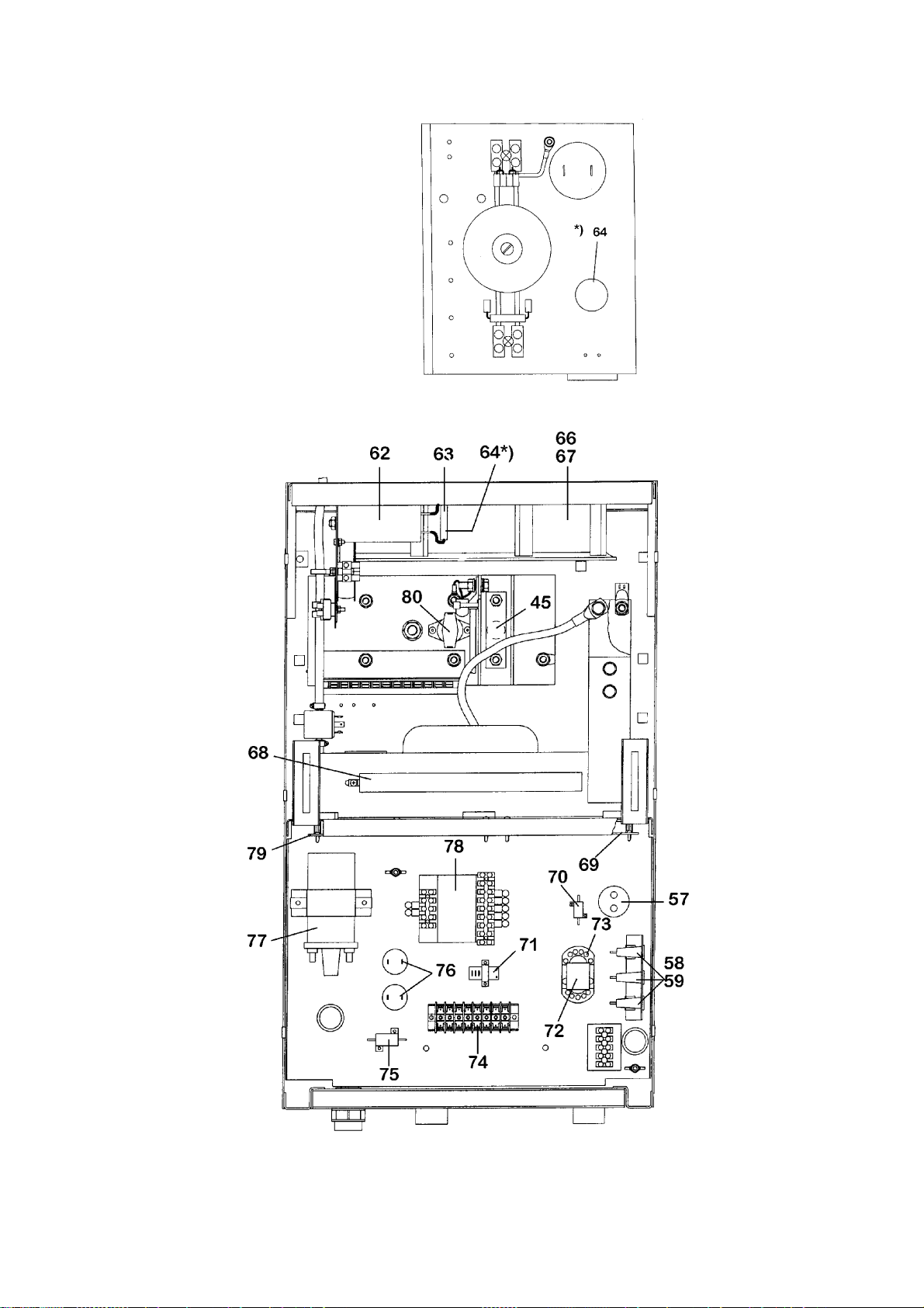
Spare parts list Список запасных частей
Edition 95.10.25
C = Component designation in the circuit diagram
Item no. Qty Orderingno. Denomination Remarks
1 1 192 576--004 Indicator lamp HL1
2 1 191 510--106 Knob
3 1 191 870--216 Potentiometer RP05
4 1 321 475--882 Knob
5 1 191 870--512 Potentiometer RP01
6 2 191 510--106 Knob
7 2 191 870--228 Potentiometer RP03,RP04
8 1 191 510--104 Knob
9 1 466 657--880 Switch SA4
10 1 368 544--003 Socket XS1
11 1 347 319 --001 Switch SA1
12 1 191 510--106 Knob
13 1 191 870--230 Potentiometer RP02
14 2 466 932--001 Side plate
15 1 160 362--881 Socket XS4
16 1 156 868--880 Socket XS3
17 1 367 258--880 Centralconnection XS2
18 1 366 285--001 Cover
19 1 347 319--001 Switch SA2
20 1 466 484--001 Fuse holder
21 1 567 900--102 Fuse FU1
22 1 347 319--001 Switch SA3
23 1 349 062--001 Switch Q01
24 1 368 708--001 Cover
25 1 193 666--003 Indicator lamp HL2
26 1 156 867--001 Grommet
27 1 2521 035--01 Nipple
28 1 5385 009--02 Sleeve socket 2 --pol.
-- 2 3 --bt10s2a

Item no. Qty Orderingno. Denomination Remarks
29 2 347 092--002 Resistor RP01,RP02
30 1 466 649--880 HF--coil L03
31 1 349 217--001 Sparkgap E1
32 1 349 218--001 Nut
33 2 152 648--001 Capacitor C20,C21
34 1 192 753--012 Connection block XT8
35 1 193 054--002 Solenoid valve YV1
36 4 349 054--001 Thyristor V02,V03
37 1 349 130--003 Bottle holder left
38 1 320 378--011 Connection block XT1
39 1 469 950--880 Cable clamp
40 1 193 655--003 Connection block XT5
41 1 349 096--001 Support
42 1 321 173--001 Chain L=700
43 1 456 194--001 Rear end plate
44 1 190 315--104 Gas hose L=2000
45 1 320 028--002 Thyristor V01
46 1 349 130--004 Bottle holder right
47 1 349 099--002 Gas shelf
48 1 469 516--004 Wheel axel L=742
49 2 469 872--001 Wheel
50 1 349 059--880 Thyristor bridge
51 1 347 496--004 Cover plate
52 1 468 480--880 Inductor compl.
53 2 469 873--001 Link wheel
54 1 349 057--001 Connection block
55 1 467 371--880 Main transformer TM1
56 1 347 597--882 Cover plate, front
57 1 192 903--045 Capacitor C10
58 3 466 484--001 Fuse holder
59 3 567 900--120 Fuse FU2,FU3,FU4
60 1 349 042--881 Handle
-- 2 4 --bt10s2a

Item no. Qty Orderingno. Denomination Remarks
61 1 369 945--880 Supressior unit
62 1 193 545--107 Capacitor CO3
63 1 191 094--160 Resistor R06
64 1 191 085--202 Capacitor C25
65 2 192 859--126 Locking washer
66 1 319 838--001 Fan cover
67 1 162 430--001 Fan EV1
68 1 349 061--001 Resistor R05
69 1 481 635--880 PC--board AP02
70 1 192 579--009 Resistor R04
71 1 193 670--003 Relay KM2
72 1 143 843--005 Relay KM1
73 1 143 843--006 Socket
74 1 466 884--008 Connection block XT4
75 1 192 579--111 Resistor R03
76 2 498 400--104 Capacitor C18,C19
77 1 156 900--002 Ignition coil GF1
78 1 349 060--880 Transformer TC1
79 1 481 366--880 PC--board AP01
80 1 368 020--001 Thermostat ST1
81 2 468 797--001 Gasket
82 2 468 796--001 Support plate
83 2 2111 030--05 Cylindrical pin
-- 2 5 --bt10s2a

OKC
-- 2 6 --bt10s2a
bt10s001
bt10s002

34
bt10s003
-- 2 7 --bt10s2a
bt10s005
bt10s004
-- 2 8 --bt10s2a


ESAB subsidiaries and representative offices
Europe
AUSTRIA
ESAB Ges.m.b.H
Vienna--Liesing
Tel: +43 1 888 25 11
Fax: +43 1 888 25 11 85
BELGIUM
S.A. ESAB N.V.
Brussels
Tel: +32 2 745 11 00
Fax: +32 2 726 80 05
THE CZECH REPUBLIC
ESAB VAMBERK s.r.o.
Prague
Tel: +420 2 819 40 885
Fax: +420 2 819 40 120
DENMARK
Aktieselskabet ESAB
Copenhagen--Valby
Tel:+4536300111
Fax:+4536304003
FINLAND
ESAB Oy
Helsinki
Tel: +358 9 547 761
Fax: +358 9 547 77 71
FRANCE
ESAB France S.A.
Cergy Pontoise
Tel:+33130755500
Fax:+33130755524
GERMANY
ESAB GmbH
Solingen
Tel: +49 212 298 0
Fax: +49 212 298 204
GREAT BRITAIN
ESAB Group (UK) Ltd
Waltham Cross
Tel: +44 1992 76 85 15
Fax: +44 1992 71 58 03
ESAB Automation Ltd
Andover
Tel: +44 1264 33 22 33
Fax: +44 1264 33 20 74
HUNGARY
ESAB Kft
Budapest
Tel:+3612044182
Fax:+3612044186
ITALY
ESAB Saldatura S.p.A.
Mesero (Mi)
Tel:+3902979681
Fax:+390297289181
THE NETHERLANDS
ESAB Nederland B.V.
Utrecht
Tel: +31 30 248 59 22
Fax: +31 30 248 52 60
NORWA Y
AS ESAB
Larvik
Tel:+4733121000
Fax:+4733115203
POLAND
ESAB Sp.z.o.o
Warszaw
Tel: +48 22 813 99 63
Fax: +48 22 813 98 81
PORTUGAL
ESAB Lda
Lisbon
Tel: +351 1 837 1527
Fax: +351 1 859 1277
SLOVAKIA
ESAB Slovakia s.r.o.
Bratislava
Tel:+421744882426
Fax:+421744888741
SPAIN
ESAB Ibérica S.A.
Alcobendas (Madrid)
Tel: +34 91 623 11 00
Fax: +34 91 661 51 83
SWEDEN
ESAB Sverige AB
Gothenburg
Tel:+4631509500
Fax:+4631509222
ESAB International AB
Gothenburg
Tel:+4631509000
Fax:+4631509360
SWITZERLAND
ESAB AG
Dietikon
Tel: +41 1 741 25 25
Fax: +41 1 740 30 55
North and South America
ARGENTINA
CONARCO
Buenos Aires
Tel: +54 11 4 753 4039
Fax: +54 11 4 753 6313
BRAZIL
ESAB S.A.
Contagem--MG
Tel: +55 31 333 43 33
Fax: +55 31 361 31 51
CANADA
ESAB Group Canada Inc.
Missisauga, Ontario
Tel: +1 905 670 02 20
Fax: +1 905 670 48 79
MEXICO
ESAB Mexico S.A.
Monterrey
Tel: +52 8 350 5959
Fax: +52 8 350 7554
USA
ESAB Welding & Cutting Products
Florence, SC
Tel: +1 843 669 44 11
Fax: +1 843 664 44 58
Asia/Pacific
AUSTRALIA
ESAB Australia Pty Ltd
Ermington
Tel: +61 2 9647 1232
Fax: +61 2 9748 1685
CHINA
Shanghai ESAB A/P
Shanghai
Tel: +86 21 6539 7124
Fax: +86 21 6543 6622
INDIA
ESAB India Ltd
Calcutta
Tel: +91 33 478 45 17
Fax: +91 33 468 18 80
INDONESIA
P.T. Esabindo Pratama
Jakarta
Tel: +62 21 460 01 88
Fax: +62 21 461 29 29
MALAYSIA
ESAB (Malaysia) Snd Bhd
Selangor
Tel: +60 3 703 36 15
Fax: +60 3 703 35 52
SINGAPORE
ESAB Singapore Pte Ltd
Singapore
Tel: +65 861 43 22
Fax: +65 861 31 95
ESAB Asia/Pacific Pte Ltd
Singapore
Tel: +65 861 74 42
Fax: +65 863 08 39
SOUTH KOREA
ESAB SeAH Corporation
Kyung--Nam
Tel:+825512898111
Fax: +82 551 289 88 63
THAILAND
ESAB (Thailand) Ltd
Samutprakarn
Tel: +66 2 393 60 62
Fax: +66 2 748 71 11
UNITED ARAB EMIRATES
ESAB Middle East
Dubai
Tel: +971 4 338 88 29
Fax: +971 4 338 87 29
Representative offices
BULGARIA
ESAB Representative Office
Sofia
Tel/Fax: +359 2 974 42 88
EGYPT
ESAB Egypt
Dokki--Cairo
Tel: +20 2 390 96 69
Fax: +20 2 393 32 13
ROMANIA
ESAB Representative Office
Bucharest
Tel/Fax: +40 1 322 36 74
RUSSIA--CIS
ESAB Representative Office
Moscow
Tel: +7 095 937 98 20
Fax: +7 095 937 95 80
ESAB Representative Office
St Petersburg
Tel: +7 812 325 43 62
Fax: +7 812 325 66 85
Distributors
For addresses and phone
numbers to our distrubutors in
other countries, please visit our
home page
www.esab.com
ESAB Welding Equipment AB
SE--695 81 LAXÅ
SWEDEN
Phone +46 584 81 000
Fax +46 584 123 08
www.esab.com
000930
 Loading...