


INSTRUCTIONS for
DIGIPULSE WIRE FEEDERS
DIGIPULSE 2 Roll Drive Wire Feeder, P/N 30680* (ESAB); 35640 (L-TEC)
DIGIPULSE 4 Roll Drive Wire Feeder, P/N 31821* (ESAB); 35658 (L-TEC)
Optional DIGIPULSE Teach Kit, P/N 35638**
* These Digipulse Wire Feeders provide preprogrammed Wire Type Material Codes 1
thru 6 (see Specifications), plus codes 7 thru 10 which are reserved for custom
applications where you can add programs for alloys such as inconel, titanium, metal
cored wire, flux cored wire, etc.
** This field-installed Teach Kit (see II-B-1) allows you to quickly develop pulse parameters
for any weldable alloy and storing up to 5 teach conditions in Material Codes 11 thru
15. The teach portion of the Digipulse is covered in booklet F-15-013.
F-15-012-B
November, 1996
SPECIFICATIONS
Input Power Required ........................................ 7 Amp., 115 vac, 1 ph, 50/60 Hz
Wire Feed Speed Range ................................... 20-999 in/min (.5-25.2 m/min)
Wire Sizes Preprogrammed .............................. .023-in. (.7 mm), .030-in. (.76 mm), .035-in. (.9 mm), .045-in. (1.2 mm), and .063-
in. ( 1.6 mm)
Wire Type (Mat.) Preprogrammed ..................... 1. Carbon Steel, 2. Alternate Steel, 3. 4043 Alum., 4. 5356 Alum., 5. Stainless
Steel, 6. Silicon Bronze, and 7. thru 10 reserved for custom application
Dimensions ........................................................ 18.5-in. (470 mm) l.,13.0-in. (330 mm) w, 16.5-in. (419 mm) h
Weight (less wire) .............................................. 46 Ibs (21 kg)
Note: This manual provides complete coverage on the Digipulse Wire Feeders starting with Serial No. WF-I512043
These INSTRUCTIONS are for experienced operators. If you are not fully familiar with the principles of operation and safe
practices for arc welding equipment, we urge you to read our booklet, Precautions and Safe Practices for Arc Welding, Cutting
and Gouging", Form 52-529. Do NOT permit untrained persons to install, operate, or maintain this equipment. Do NOT attempt
to install or operate this equipment until you have read and fully understand these instructions. If you do not fully understand
these instructions, contact your supplier for further information. Be sure to read the Safety Precautions on page 3 before
installing or operating this equipment.
Be sure this information reaches the operator.
You can get extra copies through your supplier.

CONTENTS
Specifications .................................................................................... 1
Safety Precautions ......................................................................... 3/4
I. INTRODUCTION ............................................................... 5
II. SYSTEM REQUIREMENTS .............................................. 6
A. Required Equipment ............................................................... 6
B. Optional Accessories .............................................................. 6
III. INSTALLATION ........................................................ 7
A. Unpacking and Placement ...................................................... 7
B. Power Source/Wire Feeder Control Interconnection .............. 8
C. Wire Feeder Installation Requirements .................................. 8
IV. OPERATING INSTRUCTIONS ....................................... 10
A. Power Source Welding Controls ................... Refer to F-15-014
B. Wire Feeder Control Functions ............................................. 10
C. Gas/Wire Adjustments .......................................................... 14
V. SETTING UP PROGRAM PARAMETERS ...................... 14
A. Typical Welding Conditions ................................................... 15
B. Preliminary Power Source Checks ........................................ 15
C. Program Control Parameters
(includes Hot Start Setting information) ................................ 15
Vl. WELDING OPERATION ................................................. 18
A. Pulse/Spray/Short Arc Wire Speed Recommendations ........ 18
B. Welding in Pulse or Spray or Short Arc Mode ...................... 19
C. Spot Welding ......................................................................... 18
Vll. MAINTENANCE ............................................................. 19
Vlll. TROUBLESHOOTING.................................................. 20
A. Digipulse 450 Power Source ......................... Refer to F-15-014
B. Digipulse Wire Feeder .......................................................... 20
IX. REPLACEMENT PARTS DATA ....................................22
Figure 1- Operational Sequence .................................................. 5
Figure 2 - Digipulse Interconnection Diagram ............................. 9
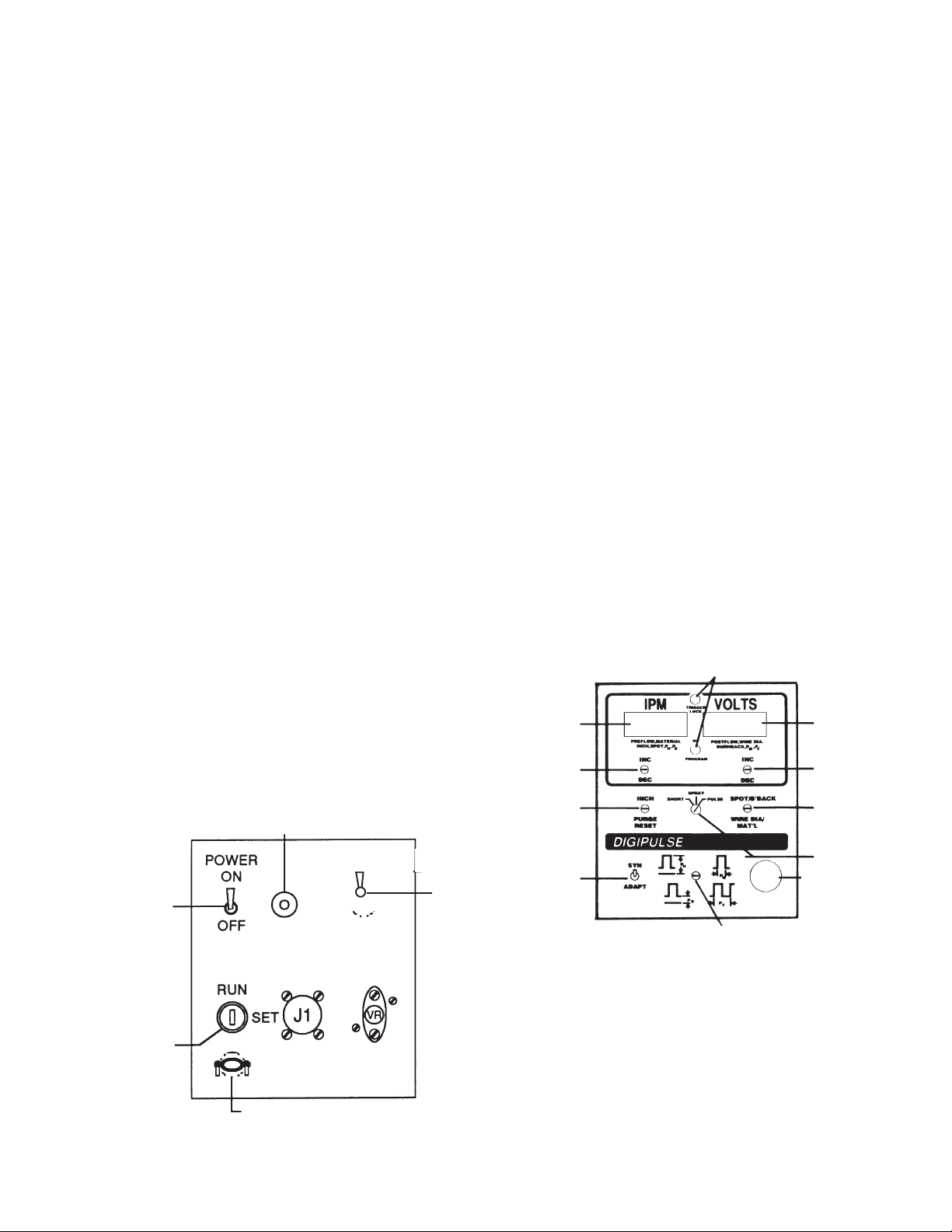
Figure 3 - Rear Panel Controls .................................................. 10
Figure 4 - Front Panel Controls .................................................. 11
Figure 5 - MPU PC Board - Dip Switch location ........................ 18
Figure 5A - Input/Output (I/O) P.C. Board .................................. 20
Figure 6 - Typical Digipulse Wire Feeder .................................. 22
Figure 7 - EH-10A Digital Motor-Gear Unit Assembly ................ 22
Figure 7A - EH-10A Motor-Gear Unit Parts Breakdown ............ 23
Figure 8 - Accessory Support Assembly .................................... 23
Figure 9 - Digipulse Control Assembly. ..................................... 24
Figure 10 - Spindle Assembly/Optional Wire reel ...................... 24
Figure 11 - Water Kit with/without Solenoid Valve ..................... 24
Figure 12 - Schematic Diagram - Digipulse XR and XRT .......... 25
Figure 13 - Wiring Diagram, Digipulse
TABLES
Table 1. - Feed rolls, feed roll kit and outlet guides ..................... 6
Table 11. - Recommended Shielding Gases ............................. 15
Table III. - Typical "Short Arc" Wire Speed Ranges .................. 17
Table IV. - Typical "Spray Arc Wire Speed Ranges ................. 17
Table V - Typical "Pulse Arc" Wire Speed Ranges ................... 17
2

SAFETY PRECAUTIONS
WARNING: These Safety Precautions are for
your protection. They summarize precautionary information from the references listed in
Additional Safety Information section. Before
performing any installation or operating procedures, be
sure to read and follow the safety precautions listed below
as well as all other manuals, material safety data sheets,
labels, etc. Failure to observe Safety Precautions can result
in injury or death.
PROTECT YOURSELF AND OTHERS --
Some welding, cutting, and gouging
processes are noisy and require ear
protection. The arc, like the sun, emits
ultraviolet (UV) and other radiation and
can injure skin and eyes. Hot metal can cause burns.
Training in the proper use of the processes and equipment is essential to prevent accidents. Therefore:
1. Always wear safety glasses with side shields in any work
area, even if welding helmets, face shields, and goggles
are also required.
2. Use a face shield fitted with the correct filter and cover
plates to protect your eyes, face, neck, and ears from
sparks and rays of the arc when operating or observing
operations. Warn bystanders not to watch the arc and
not to expose themselves to the rays of the electric-arc
or hot metal.
3. Wear flameproof gauntlet type gloves, heavy long-sleeve
shirt, cuffless trousers, high-topped shoes, and a welding helmet or cap for hair protection, to protect against
arc rays and hot sparks or hot metal. A flameproof apron
may also be desirable as protection against radiated
heat and sparks.
4. Hot sparks or metal can lodge in rolled up sleeves,
trouser cuffs, or pockets. Sleeves and collars should be
kept buttoned, and open pockets eliminated from the
front of clothing
5. Protect other personnel from arc rays and hot sparks
with a suitable non-flammable partition or curtains.
6. Use goggles over safety glasses when chipping slag or
grinding. Chipped slag may be hot and can fly far.
Bystanders should also wear goggles over safety glasses.
FIRES AND EXPLOSIONS -- Heat from
flames and arcs can start fires. Hot slag
or sparks can also cause fires and explosions. Therefore:
1. Remove all combustible materials well away from the
work area or cover the materials with a protective nonflammable covering. Combustible materials include wood,
cloth, sawdust, liquid and gas fuels, solvents, paints and
coatings, paper, etc.
2. Hot sparks or hot metal can fall through cracks or
crevices in floors or wall openings and cause a hidden
smoldering fire or fires on the floor below. Make certain
that such openings are protected from hot sparks and
metal.“
3. Do not weld, cut or perform other hot work until the
workpiece has been completely cleaned so that there
are no substances on the workpiece which might produce flammable or toxic vapors. Do not do hot work on
closed containers. They may explode.
4. Have fire extinguishing equipment handy for instant use,
such as a garden hose, water pail, sand bucket, or
portable fire extinguisher. Be sure you are trained in its
use.
5. Do not use equipment beyond its ratings. For example,
overloaded welding cable can overheat and create a fire
hazard.
6. After completing operations, inspect the work area to
make certain there are no hot sparks or hot metal which
could cause a later fire. Use fire watchers when necessary.
7. For additional information, refer to NFPA Standard 51B,
"Fire Prevention in Use of Cutting and Welding Processes", available from the National Fire Protection Association, Batterymarch Park, Quincy, MA 02269.
ELECTRICAL SHOCK -- Contact with live
electrical parts and ground can cause
severe injury or death. DO NOT use AC
welding current in damp areas, if movement is confined, or if there is danger of
falling.
1. Be sure the power source frame (chassis) is connected
to the ground system of the input power.
2. Connect the workpiece to a good electrical ground.
3. Connect the work cable to the workpiece. A poor or
missing connection can expose you or others to a fatal
shock.
4. Use well-maintained equipment. Replace worn or damaged cables.
5. Keep everything dry, including clothing, work area, cables,
torch/electrode holder, and power source.
6. Make sure that all parts of your body are insulated from
work and from ground.
7. Do not stand directly on metal or the earth while working
in tight quarters or a damp area; stand on dry boards or
an insulating platform and wear rubber-soled shoes.
8. Put on dry, hole-free gloves before turning on the power.
9. Turn off the power before removing your gloves.
10. Refer to ANSI/ASC Standard Z49.1 (listed on next page)
for specific grounding recommendations. Do not mistake
the work lead for a ground cable.
ELECTRIC AND MAGNETIC FIELDS —
May be dangerous. Electric current flowing through any conductor causes localized Electric and Magnetic Fields
(EMF). Welding and cutting current creates EMF around welding cables and
welding machines. Therefore:
1. Welders having pacemakers should consult their physician before welding. EMF may interfere with some pacemakers.
2. Exposure to EMF may have other health effects which are
unknown.
3. Welders should use the following procedures to minimize
exposure to EMF:
A. Route the electrode and work cables together. Secure
them with tape when possible.
B. Never coil the torch or work cable around your body.
C. Do not place your body between the torch and work
cables. Route cables on the same side of your body.
D. Connect the work cable to the workpiece as close as
possible to the area being welded.
E. Keep welding power source and cables as far away
3
from your body as possible.
11/95

FUMES AND GASES -- Fumes and
gases, can cause discomfort or harm,
particularly in confined spaces. Do
not breathe fumes and gases. Shielding gases can cause asphyxiation.
Therefore:
1. Always provide adequate ventilation in the work area by
natural or mechanical means. Do not weld, cut, or gouge
on materials such as galvanized steel, stainless steel,
copper, zinc, lead, beryllium, or cadmium unless positive
mechanical ventilation is provided. Do not breathe fumes
from these materials.
2. Do not operate near degreasing and spraying operations. The heat or arc rays can react with chlorinated
hydrocarbon vapors to form phosgene, a highly toxic
gas, and other irritant gases.
3. If you develop momentary eye, nose, or throat irritation
while operating, this is an indication that ventilation is not
adequate. Stop work and take necessary steps to improve ventilation in the work area. Do not continue to
operate if physical discomfort persists.
4. Refer to ANSI/ASC Standard Z49.1 (see listing below)
for specific ventilation recommendations.
CYLINDER HANDLING -- Cylinders, if
mishandled, can rupture and violently
release gas. Sudden rupture of cylinder, valve, or relief device can injure or
kill. Therefore:
1. Use the proper gas for the process and use the proper
pressure reducing regulator designed to operate from
the compressed gas cylinder. Do not use adaptors.
Maintain hoses and fittings in good condition. Follow
manufacturer's operating instructions for mounting regulator to a compressed gas cylinder.
2. Always secure cylinders in an upright position by chain
or strap to suitable hand trucks, undercarriages, benches,
walls, post, or racks. Never secure cylinders to work
tables or fixtures where they may become part of an
electrical circuit.
3. When not in use, keep cylinder valves closed. Have
valve protection cap in place if regulator is not connected. Secure and move cylinders by using suitable
hand trucks. Avoid rough handling of cylinders.
4. Locate cylinders away from heat, sparks, and flames.
Never strike an arc on a cylinder.
5. For additional information, refer to CGA Standard P-1,
"Precautions for Safe Handling of Compressed Gases in
Cylinders", which is available from Compressed Gas
Association, 1235 Jefferson Davis Highway, Arlington,
VA 22202.
EQUIPMENT MAINTENANCE -- Faulty or improperly maintained equipment can cause
injury or death. Therefore:
1. Always have qualified personnel perform the installation, troubleshooting, and maintenance work. Do not
perform any electrical work unless you are qualified to
perform such work.
2. Before performing any maintenance work inside a power
source, disconnect the power source from the incoming
electrical power.
3. Maintain cables, grounding wire, connections, power
cord, and power supply in safe working order. Do not
operate any equipment in faulty condition.
4. Do not abuse any equipment or accessories. Keep
equipment away from heat sources such as furnaces,
wet conditions such as water puddles, oil or grease,
corrosive atmospheres and inclement weather.
5. Keep all safety devices and cabinet covers in position
and in good repair.
6. Use equipment only for its intended purpose. Do not
modify it in any manner.
ADDITIONAL SAFETY INFORMATION -- For
more information on safe practices for electric arc welding and cutting equipment, ask
your supplier for a copy of "Precautions and
Safe Practices for Arc Welding, Cutting and
Gouging", Form 52-529.
The following publications, which are available from the
American Welding Society, 550 N.W. LeJuene Road, Miami, FL 33126, are recommended to you:
1. ANSI/ASC Z49.1 - "Safety in Welding and Cutting"
2. AWS C5.1 - "Recommended Practices for Plasma Arc
Welding"
3. AWS C5.2 - "Recommended Practices for Plasma Arc
Cutting"
4. AWS C5.3 - "Recommended Practices for Air Carbon
Arc Gouging and Cutting"
5. AWS C5.5 - "Recommended Practices for Gas Tungsten
Arc Welding“
6. AWS C5.6 - "Recommended Practices for Gas Metal Arc
Welding"“
7. AWS SP - "Safe Practices" - Reprint, Welding Handbook.
8. ANSI/AWS F4.1, "Recommended Safe Practices for
Welding and Cutting of Containers That Have Held
Hazardous Substances."
This symbol appearing throughout this manual
means Attention! Be Alert! Your safety is
involved.
The following definitions apply to DANGER, WARNING,
CAUTION found throughout this manual:
Used to call attention to immediate hazards which, if not avoided, will result in
immediate, serious personal injury or loss
of life.
Used to call attention to potential hazards which could result in personal injury
or loss of life.
Used to call attention to hazards which
could result in minor personal injury.
4

I. INTRODUCTION
Through the use of advanced electronics and state-ofthe-art technology, ESAB has created in the Digipulse a
high performance welding system that is extremely simple
to operate, yet much more versatile than anything previously available. The Digipulse system automatically determines all critical welding parameters in pulsed and
conventional mig short and spray arc welding applications-simply select wire type, diameter, wire feed speed,
and the Digipulse control does the rest. Note that the
power source used in this system is also suitable for
stick, scratch-start tig and air carbon arc applications
(see F-15-014).
These features are provided by advanced Digipulse
systems which combine a special Digipulse 450 ampere
inverter-type power source, and a microprocessor-based
Digipulse wire feeder/control. These system components work together to provide a pulsed or nonpulsed mig
set-up using synergic/adaptive logic that self-adjusts
while welding for optimum arc performance.
In the synergic mode, the control selects an appropriate
arc length, based on weld mode (short, pulse or spray),
for a given wire type, size and feed rate. The pulse
frequency in pulse mode remains constant regardless of
torch manipulation. This pulse logic offers many advantages to the welder, particularly where joint geometry
caused rapid changes in torch stickout resulting in unstable puddle conditions.
In the adaptive mode, the control varies the frequency
during pulse welding to maintain a constant arc voltage
regardless of changes in torch stickout or angle. This
logic is very useful where joint geometry is clean.
Heres how it works for Pulse arc operation (Fig. 1). The
Digipulse wire feeder control is preprogrammed to accommodate a wide variety of welding combinations.
These combinations are derived by selecting one of the
wire diameter sizes and wire material type that are
preprogrammed in the controls memory (available selections depend on the specific model purchased). The
operator programs one of these combinations (electing
a particular wire size and type), and a wire feed speed
(ipm) for the desired welding condition. The microcomputer then, automatically calculates the required pulse
characteristic and arc voltage, and commands the inverter power source to produce the proper output. While
welding, the microcomputer constantly monitors arc
parameters and wire feed speed, and automatically
adjusts the pulse rate to changing arc conditions. Although arc length/voltage is automatically computed for
each welding condition, this parameter can be fine-tuned
from its computed value to accommodate unique applications or operator preferences.
For conventional (non-pulsed) mig spray or short arc
applications (Fig. 1), the welding setup procedure is
exactly the same as that described for the pulse welding
mode. That is, the operator still presets a wire type
(material), wire size (diameter) and wire feed speed
(ipm) parameter from one of the available preprogrammed
welding conditions. Once these parameters are programmed, the microprocessor automatically provides
the correct arc length (for synergic operation) or arc
voltage (for adaptive operation) for a stable welding
condition. For further information regarding synergic and
adaptive mode operation, see sections IV-B-4-b., IV- B7-b., Vl-B and VI-D.
Two digital readout windows (1/2-in. high) on the control
continuously display the preset welding parameters
(speed and arc length for synergic mode; or arc voltage
for adaptive mode) as determined by the Pulse/Spray/
Short Arc mode switch. After the arc is struck, they
automatically display the actual wire feed speed and arc
WELD SET-UP PROCEDURE
As Easy As 1-2-3!
1. Select your welding processShort, Spray or Pulse.
2. Depress this key to access wire type MATERIAL
in IPM window and wire size DIAMETER in
VOLTS window select by simultaneously using
INC/DEC keys.
3. Use this key to set your wire feed speed in the
IPM window and your ready to weld!
Other parameterspre/postflow gas, spotweld,
burnback, cold inch, etc. are just as easy to add
read on!
Fig. 1- Operational Sequence
5

voltage conditions for the selected mode. The readouts
can also provide selectable displays of other applicable
welding parameters (depending on the specific model)
such as wire inch speed, spot time in cycles, manual
burnback time in cycles, gas pre- and postflow times in
tenth of a second increments. In addition, average current is displayed on the power source digital ammeter
window.
The wire feeder uses a heavy duty EH-10A wire drive
motor designed to feed hard or soft wires. Rate of wire
feed (20-999 ipm) is precisely controlled by using a
closed-loop digital feed back circuit that employs an
optical tachometer to monitor the motor speed. Arc
Voltage regulation is also controlled by a closed-loop
digital feedback circuit that monitors the arc voltage and
automatically adjusts the power source output to maintain the preset condition.
All interconnecting cable, hose and auxiliary equipment
connections are easy to install to provide quick setup as
shown in the Installation section. A water kit with or
without solenoid valve may be purchased, as an optional
accessory, for use with water cooled torches.
thickness on all materials, a water cooled torch is
recommended.
When using a water-cooled torch it will be necessary
to connect the torch water hose to either a continuous
water supply or to the wire feeder base by using an
optional water kit.
5. Gas Regulation. Shielding gas regulator/flowmeter
and fitted hose to bring gas from flowmeter to wire
feeder. Such as:
Regulator/Flowmeters:
R-5007 Argon/Helium/Nitrogen, P/N 998124.
R-5008 CO2, P/N 998125.
Standard Duty, P/N 40V77 (12-1/2-ft.) or P/N 34V38
(25-ft.)
Heavy Duty*, P/N 19416 (12-1/2-ft.) or P/N 19415 (25ft.)
* Must be used for CO2.
6. Feed Roll. The Digipulse 2-Roll Drive comes equipped
with a pressure roll but NOT a feed roll. Select the
proper feed roll from Table 1 for the wire size and type
to be used. To convert the 2-Roll to 4-Roll Drive; order
Table 1
II. SYSTEM REQUIREMENTS
A. REQUIRED EQUIPMENT
A typical Digipulse Pulsed-Mig Welding Package
requires:
1. One of the following Digipulse Wire Feeders;
a. Digipulse, 2 Roll Drive, P/N 30680.
b. Digipulse, 4 Roll Drive, P/N 31821.
2. One of the following three-phase Digipulse Power
Sources;
a. Digipulse 450i cvcc for 230/460-volt, 60 Hz service
P/N 31120, covered in booklet F-15-014.
b. Digipulse 450i cvcc for 575-volt, 60 Hz service P/N
31238, covered in booklets F-15-014 and Supplement F-15-015.
c. Digipulse 450i cvcc for 50 Hz. service P/N 31690,
covered in booklets F-15-014 and Supplement F15-039.
3. Control cable assembly as follows:
a. A 6-ft. control cable (19/c) with 19-pin amphenol
connectors each end, P/N 30686 is supplied as
part of the package. For longer length assemblies,
order one of the following:
b. 30-ft. long, control cable P/N 30780.
c. 60-ft. long, control cable P/N 30781.
4. Welding Torch. A mig welding torch, with contact tip,
wire conduit and outlet guide for wire size/type to be
employed, will be required. A suitable air (MT-400) or
water- cooled (ST-16) torch may be used with the
Digipulse. When using Digipulse systems to weld
aluminum, we strongly recommend using a MIG-41
Push-Pull Torch. For applications above 1/8-inch metal
Wire/Size Two Roll Drive Four Roll Drive Outlet
in. (mm) Feed Roll Feed Roll Kit* Guide
Soft
.030 (.8) 2075304 (U) 999320 (U) 29N13**
.035 (.9) 2075304 (U) 999321 (U) 29N13**
3/64 (1.2) 2075301 (U) 999322 (U) 29N13**
1/16 (1.6) 2075298 (U) 999323 (U) 29N13**
Hard
.023 (.6) 17998 (V) 999745 (c)
.030 (.8) 2075300 (V) 999325 (V) 993860 (a)
.035 (.9) 2075303 (V) 999326 (V) 993860 (a)
.045 (1.2) 2075302 (V) 999327 (V) 39N15 (b)
.052 (1.4) 2075330 (V) 999328 (V) 39N15 (b)
.063,1/16 (1.6) 2075299 (V) 999329 (V) 39N15 (b)
Cored Hard
.035 (.9) 19761 (Serr.) 993860 (a)
.045 (1.2) 19761 (Serr.) 999330 (Serr.) 39N15 (b)
.052 (1.4) 2075261 (Serr.) 999331 (Serr.) 39N15 (b)
.063,1/16 (1.6) 2075261 (Serr.) 999332 (Serr.) 39N15 (b)
optional 4- Roll Drive Accessory Support, P/N 600216,
and the appropriate kit listed in Table 1.
U= U-groove, V = V-groove, Serr. = serrated
(a) Includes replaceable sleeve (995651).
(b) Includes replaceable sleeve (995692).
(c) Requires guide bushing 17997.
* Includes a center wire guide and 2 upper and 2 lower feed rolls.
** Requires outlet guide as follows: For .030/.035 wire use
993902, For 3/64 wire use 05N57, For 1/16 wire use 12N57.
Recommended U-Groove Pressure Roll 2075346 be used.
B. OPTIONAL ACCESSORIES
1. Digipulse Teach Kit (P/N 35638). This field-in-
stalled kit adds pulse teach functions which allow the
operator to set unique pulse conditions by setting
pulse height (PH), pulse with (PW), pulse frequency
(PF) and background current (PB). Up to five sets of
unique pulse conditions can be stored in memory.
6

The kit includes software (EPROM), hardware (switch
and simple wire harness assembly) and installation
instructions (F-15-233).
2. Water Kit (P/N 994466). Permits the convenient
connection of a water-cooled torch and continuous
water supply or water cooler to the wire feeder.
The kit consists of a coupling, two adaptors and a
fitting. A dependable cooling water supply, delivery
and return water hoses (P/N 40V76, 2 required) will
also be required. Note that Fig. 2 illustrated the use
of power cable adaptor P/N 634693, in addition to the
kit. If adaptor (634693) is not used, adaptor (45V11
supplied with kit) can be connected to the output
terminal of the power source. Install the kit in accordance with Fig. 11 and Sec. Ill-C-7. Connect the
water-cooled torch as shown in Fig. 2.
3. Lifting Bracket (P/N 634287). Mounts on the wire
feeder spool support between the support and the
spindle assembly. Enables you to mount the wire
feeder over head on a boom.
4. Spool Enclosure Kit (P/N 600240). Provides protection of spool of wire against dust and dirt. For
installation instructions refer to Form 12-824.
5. Standard Wire Reel Assembly (P/N 995570). R e e l
slips over spindle to allow use of coiled wire, see Fig.
10.
6. Heavy Duty Wire Reel Assembly (P/N 19V89).
Spoke-type wire reel includes a four spoke aluminum alloy casting mounted on a lightweight support
shaft of steel tubing. The reel will handle all wire coils
from 2 to 4-5/8-in. wide The finger design permits
quick and easy accommodation of different coil
widths by simply rotating from one finger position to
the other.
7. Wire Straightener, (P/N 34V74). Reduces wire cast
to improve feedability and increase service life of
torch liners and contact tips. Mounts to the accessory support inlet guide.
Wire Inlet Guide, P/N 11N53 is required to complete
the installation on the wire inlet side of the straightener.
8. Four Roll Drive Accessory Support Assembly
(P/N 600216). This assembly (illustrated in booklet
F-12-821) utilizes four feed rolls to provide the backup force necessary for positive nonslip wire feed. It
is designed for feeding .030 through 1/8-in. diameter
wire(s). Feed rates using the four roll drive assembly
are virtually the same as with the two roll assembly.
For feed roll/outlet guide accessories refer to F-12821 or Table 1.
9. Cart, P/N 31700. Provides complete mobility for
Digipulse power source and wire feeder. The cart
also includes a support for gas cylinder(s) and WC8C water cooler.
10. Wire Feeder Mobile Undercarriage Kit, P/N
680005. This kit includes a mounting plate and
caster type wheels to provide complete mobility for
the wire feeder (see F-14-322).
11. Wire Feeder Turntable, P/N 678940, allows rotation of wire feeder as operator changes work positions. This reduces strain and bending of torch
cables (see F-12-984).
III. INSTALLATION
Proper installation contributes materially to the satisfactory and troublefree operation of the welding system. It is
suggested that each step in this section be studied
carefully and followed as closely as possible.
A. UNPACKING AND PLACEMENT
1. Immediately upon receipt of the equipment, inspect for
damage which may have occurred in transit. Notify the
carrier of any defects or damage at once.
2. After removing the components from the shipping
container(s), check the container for any loose parts.
Remove all packing materials.
3. Check air passages of power source for any packing
materials that may obstruct air flow through the power
source.
4. If the equipment is not to be installed immediately,
store it in a clean, dry, well-ventilated area.
5. The location of the welding equipment should be care
fully selected to insure satisfactory and dependable
service. The maximum separation between the power
source and the wire feeder should be less than 60-feet
for best performance. Choose a location relatively
close to a properly fused source of electrical power.
6. The machine components are maintained at proper
operating temperatures by forced air which is drawn
through the cabinet by the fan unit on the rear panel.
For this reason, it is important that the machine be
located in an open area where air can circulate freely
at front and rear openings. If space is at a premium,
leave at least (1) foot of clearance between the rear of
the power source and wall or other obstruction. The
area around the unit should be relatively free of dust,
fumes and excessive heat. It is also desirable to locate
the unit so the cover can be removed easily for
cleaning and maintenance.
B. POWER SOURCE/WIRE FEEDER CONTROL IN-
TERCONNECTION (See Fig. 2).
1. Remote Digital Control Connections. Voltage regu-
lation, 115- volt power, remote contactor control, and
monitoring is provided by a 19-pin receptacle, located
on the power source rear panel, which receives a
mating plug-cable assembly from the remote wire
feeder control receptacle J1.
7

These functions are provided by one of the following
19/c, amphenol to amphenol cable assemblies following:
6-ft. (supplied w/Pkg.) P/N 30686
30-ft. (optional) 30780
60-ft. (optional) 30781
2. Connect positive (+) power cable from power source
to wire feeder power terminal block, and work (-) cable
from power source to workpiece. Both cables should
be #4/0 size and should not exceed 50-ft. in length.
Cables should be the minimum length practical, and
tywrapped together to optimize output.
C. WIRE FEEDER INSTALLATION REQUIREMENTS
1. Hose and Electrical Connections. Having connected
the control cable assembly (section II-A) between the
power source and wire feeder, connect the shielding
gas and water (if used) supply hoses as shown in Fig.
2.
2. Torch Connections. Attach torch gas hose to gas
connection. Plug in torch switch cable and lock by
twisting. After inserting conduit liner (if used) and
attaching wire outlet guide of correct size, connect
wire feed conduit to welding head accessory support
clamp and lock in place. Connect torch power cable to
power source, or to power cable adaptor block (with a
second cable from that block to the power source).
3. Important Water-Cooled Torch Connections. Due
to the inherently higher power cable resistance of
water-cooled torches, the potential drop that is fed
back to the power source as arc-voltage can be in
error. To eliminate this cable drop in most watercooled torches, it is necessary to monitor the arcvoltage potential at or near the torch body itself.
In order to accommodate this desirable feature, two
water-cooled torches (MT-450W and MIG-41) were
designed to include the necessary voltage pickup
lead. The voltage pickup lead is attached to the torch
body and extends the length of the torch cables to a
single-pin Molex connector. This voltage pickup
lead connector must be connected to the wire feeder
controls pickup lead connector (J4) in place of the
accessory supports J4 connector as shown in Fig. 2
and on the Schematic diagram at the rear of this
booklet.
IMPORTANT: If competitive water-cooled torches (other
than ESAB) are used, they must be modified to add this voltage pickup lead; otherwise, they may not provide the performance desired.
4. Installing Feed Roll.
a. Release the clapper on the accessory support
assembly (Fig. 8) by disengaging the retainer from
the clapper fork.
b. Remove thumbscrew and washer from the feed roll
shaft.
c. Slip the feed roll on the shaft, engaging the key. Be
sure to observe the THIS SIDE OUT marking on
the feed roll.
d. Replace washer and thumbscrew, tightening screw
sufficiently to eliminate all end play from the feed
roll.
5. Installing Spool of Wire.
CAUTION: Make sure safety glasses with side shields
are worn when handling or changing wire, or
clipping wire off at the spool or at the end of
the torch-serious eye injury can result due to
the springiness of the wire which quickly
unravels, or a cut wire end which may shoot
across the room.
a. Remove hairpin clip from spindle.
b. Position the spool of wire so that when it is placed
on the spindle, wire will be drawn to the feed roll
from the bottom of the spool. The spool should be
held so that the index hole on the back will engage
the lug on the spindle.
c. Slide the spool onto the spindle until it engages the
lug. Lock in place with the hairpin clip.
d. Loosen the brake screw in the center of the spindle
hub, then tighten it just enough to prevent coasting
of the spool when wire is drawn from it. Too much
pressure will load the wire feed motor unnecessarily. Too little pressure will permit the spool to
overrun, causing the wire to kink and tangle.
e. Thread the wire on to the accessory support assem-
bly as described in Section C-6.
f. When wire coils are to be used instead of spools,
mount wire reel on spindle as though it were a spool
(see a. and c. above). Remove thumbnuts and
cover plate from reel. Remove coil from its package, but do not remove its binding wires. Slide coil
onto reel so that wire will be drawn from bottom of
coil (starting end for a coil is always the outer end).
Replace reel cover plate and thumbnuts. Cut off
coil tie wires and any kinked wire. Then adjust
brake screw and thread wire to torch as covered in
d. and e. above.
6. Adjusting the Accessory Support Assembly. When
a new wire size or type is to be used, set the pressure
roll adjustment as follows (see Fig. 8):
a. Round off the free end of the welding wire with a file.
b. Release the clapper and unscrew the pressure
adjusting knob until the pressure spring is free.
c. Thread the wire through the inlet and outlet guides
of the accessory support, and 3 or 4 inches into the
torch conduit.
d. Engage the clapper making sure the wire is held in
the feed roll groove.
e. Tighten the pressure adjusting knob until the wire is
8

Customers Fused Line Disconnect Switch
CAUTION: Make sure all input power is disconnected
before performing any operation inside the power source.
(See F-15-014)
Customers 3Ø Input
and Ground or use:
Factory-supplied 10ft. lg. Input power
cable (No. 6 AWG.
4/c. type SO)
connected to ONOFF switch (LS).
See F-15-014
Line Switch (LS) Rear
View - See F-15-014.
J1
Control Cable
See III-B-1
J2 See Note 2.
Input Voltage
Connections
(See F-15-014)
TO WORK
NEG. (-)
OUTPUT
For Wire Feeder
Torch & Service
Connections
See Below
Approved
Earth Ground
Work
To Wire Feeder
See III-B-2
4/0 WELDING
CABLES
(Cust. Supplied) are
set-up for DCRP
(Neg. to work)
Operation, see
NOTE 1. below
MALE
CONNECTOR - 950693
(Supplied w/Power
Source)
ACCESSORY SUPPORT
VOLTAGE PICK UP LEAD
See Sec. III-C-3, and
Schematic Diagram
TORCH CONDUIT
TORCH SWITCH
TORCH WATER HOSE
TORCH GAS HOSE
MIG-41 VOLTAGE
PICKUP LEAD - See III-C-3
FRONT VIEW
WATER KIT 994466*
ADAPTOR 45VII*
Power Cable
Adaptor Assy. 634693
TORCH POWER CABLE
WATER DRAIN HOSE - 40V76 (12-1/2 FT.)*
WATER IN HOSE - 40V76 (12-1/2 FT.)*
REAR VIEW
REGULATOR/
FLOWMETER
(See II-A-5)
GAS HOSE
(See II-A-5)
* PARTS REQUIRED WHEN
USING A WATER KIT &
WATER COOLED TORCH
IMPORTANT NOTE:
1. Both output welding cable leads (torch and work) must be a minimum size of No. 4/0 welding cable (nothing smaller), and
both leads should be kept as close to the same length as possible - with neither lead exceeding 50-ft. in length. Also, both
cables must be run next to each other and tywrapped every couple of feet to minimize cable reactance.
2. Make sure that all Tig/Stick Controls are physically unplugged from the power source receptacle J2 when a Mig setup is to
be used.
Fig. 2 - Digipulse Interconnection Diagram
9

firmly against the feed roll - do not overtighten. The
spring pressure applied should be the minimum
required to provide positive, nonslip wire feed. Too
little pressure will result in wire slippage while
excessive pressure will scar and deform the wire.
Further adjustment can be made after the wire feed
is put into operation. Note that a light spring
(182W55) is installed on the accessory support for
use with soft and small diameter hard wire. For
large diameter hard wire, replace this spring with a
heavy spring (182W54) supplied with the unit.
7. Water Kit (Optional see Fig. 11). Mount bulkhead
adaptor (58V75) behind opening provided in vertical
base plate, above gas connection, and secure with
screws (No. 8-32 x 3/8-in.) and lockwashers provided.
Attach coupling and adaptor ( 11N16) behind bulkhead adaptor. Mount torch cable adaptor (45V11) on
welding power stud. Connect water drain hose to this
adaptor and water inlet hose to adaptor 11N16.
IV. OPERATING INSTRUCTIONS
CAUTION: Never, under any circumstances, operate
the power source with the cover removed. In
addition to the safety hazard, improper
cooling may cause damage to internal components. Keep side panels closed when unit
is energized. Also make sure you are adequately protected before you start welding
- welding helmet, gloves, eye and ear protection should always he worn.
Do not allow metal-to-metal contact between the
wire feeder chassis and a metal surface connected
in any way welding round. With such contact a poor
welding ground connection may create a difference
in potential that sends part of the welding current
through the safety ground wiring in the control cable
and wire feeder resulting in burnout of that wiring
and/or damage to wire feeder circuitry. If the safety
ground burns out, the operator may be exposed to
115V. shock hazard.
A. POWER SOURCE WELDING CONTROLS
For detailed information regarding the power source
welding controls, refer to F-15-014.
B. WIRE FEEDER CONTROL FUNCTIONS
For location of rear panel control features, refer to
Figure 3 following:
1. Power Switch. This two-position toggle switch turns
power on or off to the wire feeder control.
2. Lock-ln Key. This key-operated switch must be in
the SET position to preset, vary and weld-test the
welding parameters programmed into the control.
After the desired results are achieved, the program(s)
can be locked-in by turning the key to the RUN
position. The only parameter which can be altered by
the operator in the RUN position is the cold wire INCH
speed.
3. Reset Circuit Breaker. A seven (7) ampere circuit
breaker provides protection to the 115-volt control
circuit and the wire feed motor. If an overload occurs,
the breaker will trip and suspend all operation. To
restore service, depress the breaker button to reset
the circuit.
3A. Trigger Lock/Crater (Fill) Switch. the toggle-
configuration position of this switch follow:
toggle-center is the normal maintained
OFF position for the Trigger-Lock function, and/or normal spring-return rest
position for the toggle-configuration positions as follows:
toggle-up is the maintained ON position
to provide the Trigger-Lock function.
Toggle-down is the momentary ON posi-
tion to program Crater Fill (or alternate
schedule) parameters to a primary
preprogrammed conditions.
Please note that either of these features
can be set or programmed individually, or
combined to provide both functions with a
preprogrammed condition (codes 1-10).
Neither of these features, however, are
available in the teach codes 11-15. Also,
when programmed, these functions are
automatically locked into all
preprogrammed codes (until they are
removed or programmed-out), and this
will be indicated by the energized Trigger Lock indicating light on the front
panel. To set and/or program thee func-
tions, see the following:
IMPORTANT: If a SPOT weld function has been
added to the existing programmed
codes 1-10, it must be removed (zeroed-out) before either of these functions (trigger lock/crater fill) can be
set or programmed.
a. Trigger Lock function. To set this function in a
condition, simply place the switch toggle to its (ON
(p) position. This feature allows the operator to
release the torch switch (trigger-lock on) after
starting the welding cycle. To stop the welding
cycle, you simply repress the torch switch again
and all welding action ceases. Remember that the
front panel Trigger Lock indicating light will be on
when this feature is engaged. In the OFF position,
this function is inactive.
10
b. Crater Fill function. This function actually serves
a dual purpose: first, it allows you to alter your
primary welding condition (speed/voltage) by selecting a slightly different condition to achieve crater-fill at the end of your weld;' or second, the
sequenced-in crater condition can actually be used
as an alternate schedule controlled by the torch
switch. For example; set up a hot condition in the
standard weld mode, and a cold condition in the
crater-fill mode for bridging gaps. To program this
feature, refer to Section V-C-10A.
c. Combined Trigger Lock/Crater. If you wish to
add the crater-fill feature to the trigger-lock function, do the following:
(1) Program the Crater-Fill parameters (wire speed
and voltage) as described in section V-C-10a.
(2) Place the Trigger-Lock in its on (up) position
as described in 3A-a. above.
(3) Depress the torch trigger to start the arc, re-
lease the trigger (lock-in mode) and weld using
the primary weld condition. Depress the trigger
again and the crater (or alternate schedule)
conditions will take over. When the trigger is
released the arc will terminate.
(4) To remove these functions, place the trigger
lock toggle to its center off position, and then
hold-down the toggle to its crater position and
zero-out the setting in the IPM window.
For location of the following front panel control
features, refer to Figure 4 following:
4. Digital Readout Window. Two individual three-digit
windows are provided to display preset or actual
welding parameters as follows:
a. IPM Digital Readout. This window is primarily
used to display actual and/or preset wire feed
speed* in a range from 20 to 999 inches per minute
in one inch increments. However with the appropri-
ate function selector actuated, this window can
also display the following:
* With power turned ON, but not welding, the IPM
window will continuously read the Preset wire
speed setting. When the arc is struck, the IPM
window will then continuously read the actual welding wire speed as the weld conditions cycle thru the
welding sequence.
shielding gas PREFLOW from .1 to 99.9 sec-
onds in one tenth of a second increments
a code number indicates a type of MATERIAL
which is programmed for various welding wire
applications, as follows: code #1 indicates Carbon Steel, #2 is Alternate Steel, #3 is 4043
Aluminum, #4 is 5356 Aluminum, #5 is 308
Stainless, #6 is Silicon Bronze. (Additional Ma-
terial code numbers 7 thru 10 are reserved
for custom applications.)
SPOT welding time from 1 to 999 cycles in one
cycle increments.
cold wire INCH speed in IPM from 40 to 999
inches per minute in one-inch increments
if provided, Ph indicates PULSE HEIGHT which
is displayed as a reference voltage setting,
from 0.1 to 10 (in 0.1 volt increments), that
controls or establishes the amplitude of the
pulse peak (in Teach option only).
if provided, Pb indicates PULSE BACKGROUND
which is displayed as a reference current setting, from 15 to 100 (in one ampere increments),
6
4a
7a
4b
7b
3
1
2
STRAIN RELIEF
Fig. 3 - Rear Panel Controls
TRIGGER
LOCK
CRATER
3A
9
10
11
Fig. 4 - Front Panel Controls
that establishes the approximate background
current in pulse applications (in Teach option
only).
b. Volts Digital Readout. This window is primarily
used to display an arbitrary number (100) that
represents a programmed arc length in the synergic mode*, or a computed arc voltage in the
adaptive mode**-with power on, but not weld-
11
8
5
TORCH
SW.
RECPT.

ing. When the arc is struck, the VOLTS Window will
continuously display actual welding voltage in a
range from 12 to 50 vdc in one-tenth (0.1) volt
increments. However, with the appropriate function selector actuated, the VOLTS Window will
also display the following:
* In the synergic mode, the control will automati-
cally select and display an appropriate arc length
integer for a given wire type, size, feed rate and gas
shielding. An arbitrary number, represented by the
integer If 100, is the normalized value for all applications programmed in the control, and this figure
will be displayed in the VOLTS window during
setup (not welding). This value (set at 100) can be
readjusted within a range from 0 to 200, to finetune the operating arc length of the selected welding condition. By reducing the number below 100
(minimum 0) you will reduce the arc length. Conversely, by increasing this value above 100 (maximum 200) you can increase the arc length. After
the arc is struck, the number will be replaced by
the actual welding arc voltage.
** The Digipulse can also operate in the adaptive
mode, where the arc is continuously monitored by
a closed loop feedback circuit and the machine
modulates its output to maintain a given voltage for
preprogrammed data. In the adaptive mode, a
computed arc voltage (unique to your
preprogrammed welding selection) will be displayed
in the VOLTS window before welding. Once the
arc is struck, the control will measure the actual
welding voltage and change the output of the power
source to maintain the precalculated voltage setting. In this manner, the power source automatically compensates for variations in stickout or weld
joint geometry Further, all of the precalculated arc
voltages programmed in the control can be readjusted +/-10 volts to fine-tune the welding arc.
shielding gas POSTFLOW from .1 to 99.9 sec-
onds in one tenth of a second increments.
a pair of numbers represent WIRE DIA. sizes
which are programmed for selection as follows#23 represents .023" dia., and #30 is .030" dia.;
#35 is .035" dia., #45 is .045" dia. hard (3/64" dia.
soft) and #63 is .063" (1/16") dia.
manual BURNBACK time. Manually adjustable
burnback time period which when preset overrides the automatic adaptive anti-stick feature.
This time period will be set in one-cycle increments (60 cycles = 1 sec.). When set to zero,
the auto-adaptive-anti-stick feature is operational.
if provided, Pw indicates PULSE WIDTH which
is displayed as a reference time setting, from
1.0 to 10 (in one-tenth millisecond increments),
that measures or establishes the width of pulse
duration (in Teach option only).
if provided, Pf indicates PULSE FREQUENCY
which is displayed as a frequency (Hertz) reference setting, from 25 to 909* pulse cycles per
second, that establishes the approximate pulse
frequency required for the wire feed speed set
on the control (in Teach option only).
* Please note that the number of pulse/sec is
dependent on the pulse width the narrower
the width, the fewer the cycles; and the wider the
width, the more the cycles.
5. Pulse-Short (Arc)-Spray (Arc) Selector. This threeposition rotary switch allows you to select the welding
process mode you wish to use Pulsed mig spray arc,
or non-pulsed mig Short Arc, or non-pulsed mig
Spray Arc.
In all process modes, the operator simply codes the
control (wire diameter and material) for any one of the
preprogrammed welding conditions, sets the desired
wire feed speed (ipm) and the control automatically
provides the proper welding parameters to produce
the necessary output for the process selected.
6. L.E.D. Indicator Lights. Either or both of these LEDs
will light to indicate the following:
The NO PROGRAM l.e.d. will only light if you select
a wire type (Material) and size (Diameter) that is not
programmed in the control. In addition, if you close the
torch switch, the power source will not energize and
the Digipulse will not feed wire in this condition.
The TRIGGER LOCK l.e.d. will only light to indicate
that either one, or a combination, of three special
features (Trigger Lock, or Crater Fill, or Alternate
Schedule) has been programmed on to a selected
welding condition. Further, having been programmed,
this feature will always be included in all process
modes and programmed welding conditions until it is
zeroed-out and removed. (Additional details regarding programming and operation of these features are
covered in sections IV-B-3a and V-C-10a.
NOTE: All of the following controls are springloaded,
center-return toggle switches which must
be operated to actuate their indicated
function(s). Item No. 7, Inc/Dec toggle
switches, describes the adjustment setting
toggle used to preset the program-function
selectors. Except as noted above and following, regulation for selected function(s) can
only be made if the Lock- In key, described in
Item No. 2 is in the SET position.
7. Inc/Dec Toggle Switches. Two control toggles are
provided to preset the individual welding parameters
required for the selected welding mode, PULSE,
12

SPRAY or SHORT arc, as follows:
a. IPM Increase/Decrease Control. This toggle
switch is primarily used to set and/or vary the wire
feed speed (IPM), along with its other functions
(when provided); Preflow, Material, Inch, Spot, PH
and PB. With the appropriate function selector
actuated, each parameter setting will be displayed
in the digital window directly above this toggle.
b. VOLTS Increase/Decrease Control. This toggle
switch is primarily used to set and/or vary VOLTAGE*, along with all its other functions; Postflow,
Wire Dia., Burnback, PW and PF. With the appropriate function selector actuated, each parameter
setting will be displayed in the digital window directly above this toggle.
* Please note that the term VOLTAGE denotes
arc voltage (in the adaptive mode) and/or arc
length (in the synergic mode) and is the computed value that has been precalculated for
each of the combinations programmed into the
control. And further, any of these computed
voltages can be altered (+/-10 volts in the adaptive mode; and +/-100 numerals from its midrange
value of 100 in the synergic mode) to fine tune
the welding arc; however, having done so, th e
computed voltage value(s) is altered for all of the
other preprogrammed wire size/type combinations.
Therefore, if the computed voltage for your
selected welding combination had been altered
and you plan to use a new combination (a
different wire size and/or type), it is suggested
that the control be reset to provide the
correct voltage computed for the
preprogrammed combination as follows:
Adaptive Mode. To reset the computed arc
voltage value for a given wire size and type,
place the Run-Set key switch in its SET position
and then decrease the arc voltage key until the
number in the VOLTS window stops This number is 10 volts below the computed or midrange
value. To establish the computed value, add 10
(volts) to the displayed number using the increase (INC) portion of the Volts Inc/Dec key.
Synergic Mode. Resetting the computed value
in this mode is much simpler-remember that the
computed or midrange value is the arbitrary
numeral 100 (this number represents a
precalculated arc length based on the wire
feed speed of the programmed wire size and
type). Therefore, if the number appearing in the
VOLTS display window is any numeral between
0 and 200 (other than 100) simply use the
appropriate Inc/Dec key to reset the condition to
the numeral 100.
8. Spot/Burnback - Wire Dia./Material Selector.
Operating this toggle allows you to select the following:
a. Access the SPOT/BURNBACK time mode (up
position) to preset either or both of these welding
features into a preprogrammed weld condition;
however, once preset, these features automatically become part of all preprogrammed weld conditions in all these process modes.
The SPOT mode allows you to preset timed arc
periods from 1 to 999 cycles in one cycle increments (60 cycles/sec) in the IPM window using its
Inc/Dec toggle switch. When a spotweld time is
preset into the control, all continuous- type welding programs are temporarily disabled. To resume normal (continuous) operation, you must
deactivate the spotweld program by keying its
time parameter back to zero (000).
At the same time (or independently), you can also
preset a manual BURNBACK time into the VOLTS
window using its Inc/Dec toggle switch. The Burnback time is adjustable in one cycle increments (60
cycles/sec); and when preset, it will override the
automatic adaptive anti-stick feature. If automatic
anti-stick operation is desired, the preset Burnback
time must be set back to zero.
NOTE: Actuating the Spot/BBack position when the
control is set-up to operate in the PULSE mode
and the torch switch is energized, allows you
to read the actual pulse frequency (for a
preprogrammed pulse condition) in the VOLTS
display window. (If this position is actuated during a standard mig short or spray arc welding
operation, the numbers appearing in the Volts
display window are not related to the actual
condition.)
b. Access the WIRE DIA/MATERIAL, mode (down
position) to select one of the welding conditions
preprogrammed into the control, as follows:
To select the type of wire MATERIAL, actuate
the INC position of the Inc/Dec switch below the
IPM window (while holding the Wire Dia/Matl key
down) until the desired code number for your
material selection appears in the IPM window,
and these material codes follow: #1 is carbon steel,
#2 is alternate steel #3 is 4043 aluminum, #4 is
5356 aluminum, #5 is 308 stainless, #6 is silicon
bronze. (Additional Material codes 7 thru 10 are
reserved for custom applications.)
Now select the Wire DIA. size to be used, by
actuating the INC position of the Inc/Dec switch
below the VOLTS window (while holding the Wire
Dia/Matl key down) until the desired pair of num-
13

bers for your wire size selection appears in the
VOLTS window, and these wire diameter numbers
follow: #23 is 023" dia, and #30 is 030" dia.; #35 is
035" dia., #45 is 045" dia. hard (3/64" dia soft), and
#63 is 063" ( 1/16") dia.
NOTE: Accessing the WIRE DIA/MAT'L and the
PURGE/RESET selector keys (simultaneously) during an actual weld, allows you
to check the factory-preset numbers that
determine the quality of starts (hot, cold,
etc.) for your preset welding condition. These
numbers are preset to provide optimum starting
characteristics required for most welding applications. This is a diagnostic tool available to the
experienced operator or serviceman and need
not be activated during a normal operation unless you are experiencing weld starting problems, or weld condition (speed and /or voltage)
aborting problems. It must also be noted that
only the speed (IPM) condition can be
checked when a unit is operating in the
synergic mode (the VOLTS Window will
always display the number 100) and cannot
be adjusted; however, in the adaptive mode
both speed and voltage conditions can be
checked and adjusted. The factory-set start-
ing condition is represented by numbers that are
displayed, on command, in the digital IPM and
VOLTS windows. For good welds and starts,
these numbers should be in a range from 105 to
115 (with 110 being the norm) in the IPM window
(synergic and adaptive mode), and from 90 to
100 (with 95 being the norm) in the VOLTS
window (adaptive mode only) If your weld starts
are not acceptable, please refer to Section VB-Il for a simple adjustment procedure that
will enhance good starting. If you are experi-
encing frequent speed and/or voltage aborts,
please refer to Section Vlll-B-7 (Troubleshooting) for checking and resetting condition functions.
9. Inch-Purge/Reset Selector.
Operating this toggle allows the following functions:
a. The INCH selection permits cold-wire inching
without energizing the welding circuit through the
torch switch. The wire inching speed can be independently controlled by operating its Inc/Dec toggle
switch.
b. The PURGE/RESET position provides the fol-
lowing when actuated:
(1) During initial programming, it permits pre-
setting of gas PREFLOW and POSTFLOW
time requirements which are simultaneously
displayed in the IPM and VOLTS windows
respectively.
(2) Prior to actual torch triggering, it permits
you to actuate the gas solenoid and PURGE
the shielding gas line of the torch. At the same
time, it also lets you adjust the gas regulator
without energizing the welding circuit.
(3) After starting the welding sequence, if an
abort-shutdown condition occurs (indicated
by a flashing digital display), the RESET position can be actuated and the control automatically resets for a new start.
(4) When this key is actuated during a weld,
and simultaneously with the Wire Dia/Matl
key, a diagnostic operation allows you to check
the preset numbers (displayed in the IPM and
VOLTS windows) that determine the quality of
starts (hot, cold, etc.) for your preset welding
condition (see NOTE following IV-B-8- b).
10. SYN.-ADAPT. Switch. This switch allows front-
panel selection of synergic or adaptive logic modes.
The operating characteristics of synergic vs. adaptive logic in the welding operation are covered in
sections I, IV-B-4-b, IV-B-7-b, Vl-B and -D. Please
note that either type of logic can be used in the a
preprogrammed material codes #1-#10; however,
only the synergic logic can be used in the teach mode
material codes #11-#15.
11. Teach Pulse Parameter Switch (Teach option
only). This switch allows you to program Pulse
Height (PH), Pulse Width (PW), Pulse Background
(PB), and Pulse Frequency (PF) teach parameters
into material codes 11 thru 15. These features and
operating functions are fully covered in the Teach
supplemental booklet F-15-013.
C. GAS/WIRE ADJUSTMENTS
The following wire feed control functions must be made
to feed wire through the torch conduit and to adjust the
shielding gas flow rate.
1. Place Power switch (on rear panel) to on position to
energize the control
2. Place key-operated Run-Set switch in Set position
3. With torch connection made as shown in Fig 2, and
wire engaged in accessory support (Sect III-C-6), feed
wire through torch conduit and into torch as follows:
a. Remove nozzle and contact tip from torch.
b. Hold Inch-Purge toggle in INCH position (Sect IV-
B-9) until cold wire protrudes from the torch front
end.
c. Slide the contact tip over the end of the wire and
secure it to the torch. Replace the torch nozzle.
d. Reoperate the Inch-Purge toggle in INCH position
and check for wire feed slippage on the accessory
support assembly. Tighten (or loosen) the pressure adjusting knob until the wire feeds smoothly.
4. With shielding gas cylinder and torch gas hose connection assembled as shown in Fig. 2, set gas flow
rate as follows:
a. Hold Inch-Purge toggle in PURGE position and
open the gas regulator-flowmeter control valve and
set the shielding gas flow rate.
14

b. Continue to hold the Purge position for approx. 15
seconds to insure adequate purging of gas hose
and torch.
5. Place controls Power switch to off position.
\/. SETTING UP PROGRAM PARAMETERS
A. TYPICAL WELDING CONDITIONS
Three sets of welding (process) mode parameters can
be preset in your Digipulse control; one for the PULSE
mode, one for standard SPRAY arc mode, and another
for standard SHORT arc mode.
The setup procedure for each welding arc mode is
exactly the same, except for wire feed speed input and
gas shielding requirements which may be peculiar to
each process. The following parameters are provided as
an example of a Typical Welding Condition which can
be used to set-up all welding modes, with exceptions as
noted.
Typical Welding Condition (Parameter):
Cold Wire Inch Speed .............................................. 75 IPM*
Type Material ...................................................... 1 (Steel)
Wire Dia. ......................................................... 45 (.045-in.)
Wire Feed Speed ..................................................... 185 IPM
Arc Voltage/Arc Length ........ Preprogrammed for MAT./DIA.
Spot Weld Time ................................................... 45 Cycles*
Preflow Time .................................................... 1.2 Seconds*
Postflow Time .................................................. 3.1 Seconds*
Burnback Time ....................................................... 7 Cycles*
Trigger Lock/Crater Fill ...................... Program Parameters*
* If programmed, these parameters are automatically incorporated
in all other preprogrammed welding conditions until they are
programmed (zeroed) out.
For recommended shielding gases used for preprogrammed
welding wire material, see Table II.
B. PRELIMINARY POWER SOURCE CHECKS
Before programming the wire feeder control, make sure
that the power source is properly set-up as follows:
Check the rear panel of the power source to make
sure that only the Digipulse control cable is connected. The remaining stick control receptacle/cable
must be disconnected.
Depending on the welding process mode programmed
on the wire feeder control, set the power source
INDUCTOR control pot as follows:
For SHORT ARC mode, set Inductance @ 12 Oclock
position and adjust for best performance when welding.
For PULSE and SPRAY ARC modes set Inductance
@ MINIMUM .
C. PROGRAM CONTROL PARAMETERS
Remember, the following procedures represent a typical
example of how to set-up one of the many preprogrammed
welding conditions available in this control and that these
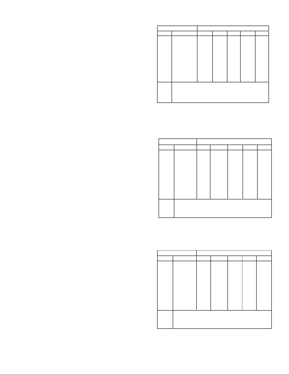
Table II
Recommended Shielding Gas
Wire Material Welding Arc Mode
Code # Type Short Arc Spray Arc Pulse Arc
1 Carbon Steel CO
2 Alternate Stl. C-25 Stargon/C-8 Stargon/C-5
3 4043 Aluminum Argon Argon
4 5356 Aluminum Argon Argon
5 308 Stainless A1025 1%/2%O
6 Silicon Bronze Argon Argon
7*
8*
9*
10*
* These codes are reserved for custom applications.
/C25 C-5/C- 8 C- 5
2
Pulse SS
2
procedures are the same for all weld arc modes Pulse
Spray, or Short Arc. The only difference(s) between weld
arc modes (for the same Wire Diameter and Material)
will, or may, be your wire feeder speed (IPM) and gas
shielding selection the control automatically provides
the required welding voltage for every condition, and
even this parameter (voltage) can be fine-tuned as
described following.
1. Set the Power switch (on rear panel) to the on
position to energize Digipulse Control.
2. Place the rear panel key switch in its SET position to
preset all welding parameters. In this position the
operator or supervisor is free to weld and make any
changes before locking-them-in, in the RUN position.
3. Set the PULSE, SPRAY, SHORT arc mode switch to
the process you wish to preset. And set the Synergic
- Adaptive switch to the logic mode you wish to use.
4. To set the type of Wire Material (carbon steel) and
Wire Diameter (.045 in.) to be used, depress and
hold WIRE DIA/MATERIAL toggle switch in its down
position and simultaneously preset each of the following:
a. Operate (increase or decrease) the left INC/DEC
toggle switch lever until a 1 (indicating carbon
steel wire) appears in the IPM display window.
b. Now operate (increase or decrease) the right
INC/DEC toggle switch lever until 45 (indicating
.045-in. dia. wire) appears in the VOLTS display
window.
NOTE: If no program exists for a given material or
diameter, a No Program l.e.d. on the front of
the control will light.
5. To set a Wire Feed Speed parameter of 185 ipm,
raise and hold the toggle of the left Inc/Dec switch in
its INCREASE position until 185 appears in the IPM
window. Notice that this parameter setting will start at
zero and immediately jump to 20 and then rapidly
increases (1 ipm at a time) until the 185 ipm setting is
reached. If you overshoot the planned setting, simply
bump the DECREASE position of the left Inc/Dec
toggle to obtain the exact IPM setting.
15

6. After items 4 and 5 have been preset, the microcomputer automatically sets a preprogrammed arc
voltage in the adaptive mode or arc length integer in
the synergic mode that will be displayed in the VOLTS
window. If this precalculated value* does not provide
a stable condition, it can be fine-tuned by using the
right-side Inc/Dec toggle switch-as described in IV-B7-b.
* If the existing welding condition is altered (fine tuned),
it is suggested that each time a new wire size/type is
used that you reset the control to set up the original
computed (mid-range) arc voltage values as described
in Section IV -B-7-b.
NOTE: The remaining parameters can also be pro-
grammed into the selected mode of operation; however, when preset, these parameters will automatically be operational in all
process conditions.
7. To set a Cold Wire Inch parameter of 75 ipm, raise
and hold the toggle of the Inch-Purge/Reset switch
in its INCH position. Simultaneously, raise and hold
the toggle of the left Inc/Dec switch in its INCREASE
position until 75 appears in the IPM window. Note
that the cold inch setting starts at 40 ipm and rapidly
increases (1 ipm at a time) until the 75 ipm setting is
reached. If you overshoot the planned setting, simply
bump the DECREASE position of the left Inc/Dec
toggle to obtain the exact IPM setting.
8. To set shielding gas Preflow and Postflow times
of 1.2 seconds and 3.1 seconds respectively,
depress and hold the toggle of the Inch-Purge/
Reset switch in its PURGE/RESET position. Simultaneously, raise and hold the toggle of the left Inc/
Dec switch in its INCREASE position until 1.2 seconds of Preflow time appears in the IPM window and
then; repeat this procedure using the right Inc/Dec
switch until 3.1 seconds of Postflow time appears in
the VOLTS window. Both of these parameter settings will start at zero and rapidly increase ( 1/10
second at a time) until the desired time is achieved.
If you overshoot the planned settings, simply bump
the DECREASE position of the respective Inc/Dec
toggles to obtain the desired Preflow and Postflow
time settings.
9. To set a Spotweld time of 45 cycles, raise and hold
the toggle of the Spot/Burnback - Wire Dia/Material
switch in its SPOT/Burnback position. Simultaneously, raise and hold the toggle of the left Inc/
Dec switch in its INCREASE position until 45 cycles
appears in the IPM window ( note: 60 cycles = 1
sec.). This parameter setting will still start at zero and
rapidly increase (1 cycle at a time) until the 45 cycle
time is achieved. If you overshoot the planned setting, simply bump the DECREASE position of the
left Inc/Dec toggle to obtain the desired Spot cycle
setting.
10. To set a manual Burnback time of 7 cycles, raise
and hold the toggle of the Spot/Burnback - Wire Dia/
Material switch in its Spot/BURNBACK position.
Simultaneously, raise and hold the toggle of the
right Inc/Dec switch in its INCREASE position until
7 cycles appears in the VOLTS window (note: 60
cycles = 1 sec.) This parameter setting will start at
zero and rapidly increase (1 cycle at a time) until the
7 cycle time is achieved. If you overshoot the planned
setting, simply bump the DECREASE position of
the right Inc/Dec toggle to obtain the desired Burnback cycle setting.
Remember if a manual Burnback function is
programmed, it will override the standard automatic
adaptive anti-stick feature in all welding modes.
10-A. To program a Crater Fill Function do the fol-
lowing:
a. Set a process, material type and wire diameter
combination, for example; pulse welding, material code 1 and diameter 045. This will be your
primary welding condition. Note the Trigger Lock/
Crater Switch functions are described in section
IV-B-3A.
b. Hold the Crater Fill/Trigger Lock switch down.
Set the desired wire feed speed and voltage
required to achieve the crater fill results. These
crater parameters will be displayed in the appropriate will be displayed in the appropriate IPM
and VOLTS window. Release the CRATER
switch.
c. Depress the torch trigger and weld using the
primary welding condition. Release the trigger
and the crater (or alternate schedule) conditions
will take over. Depress the trigger again and the
arc will terminate.
d. To remove the crater fill parameters, hold down
the CRATER key and zero out the setting in the
IPM window (it is not necessary to zero the
VOLTS window).
e. If you wish to combine the Crater-Fill feature to
the Trigger Lock function, refer to section IV-B3A.
11. Using the torch switch, the selected process mode
parameters can be weld-tested and if necessary
readjusted. If your weld starts are not acceptable,
refer to the following Hot Start adjustment procedures that will enhance starting.
Hot Start Adjustment Procedures
As mentioned earlier in the italicized Note following
Section IV-B-8-b, the control is preset at the factory to
provide the optimum starting characteristic for most
welding conditions. However, due to factors such as
inaccurate parameters (for a given wire type and size),
welding technique, shielding gas, or wire feed speed,
you may have to readjust the factory-set starting
16
characteristics to provide the best arc starts possible.
To do this, it is necessary to readjust the factory-set
calibrations to provide a hot start characteristic in
which the initial starting voltage (open-circuit voltage)
will be slightly higher than actual welding voltage ( arc
voltage) and speed which initially is somewhat lower
than the selected wire feed speed desired.
To set-up the control to provide this, do the following:
a. Program the welding condition you need in the IPM
(wire feed speed) and VOLTS (arc voltage) windows, and fine-tune these parameters until you
have the welding arc desired. Do not at this point
concern yourself with the arc starts, this follows.
b. If after the welding condition is fine-tuned you find
that the arc starts are unsatisfactory, proceed as
follows:
(1) During an actual weld, actuate and hold the
Wire Dia/Matl. and Purge/Reset key positions
(simultaneously) and observe the numbers
displayed in the IPM and VOLTS windows.
Table III for Typical Short Arc Wire Speed Ranges
Wire Material Wire Diameter & Wire Speed Ranges
Code# Type .023 .030 035 .045 .063
1 Carbon Steel 175- 180- 130- 130- NP
500 600 600 450
2 Alternate Stl. 125 175- 100- 100- NP
350 350 300 250
3 4043 Alum. NP NP NP NP NP
4 5356 Alum. NP NP NP NP NP
5 308 Stainless 250- 100- 75- 50- NP
450 400 300 250
6 Sil. Bronze NP NP NP NP NP
7**
8**
9**
10**
** These codes are reserved for custom applications.
NP Not programmed.
Table IV for Typical Spray Arc Wire Speed Ranges
Remember that only the speed (IPM) condition
can be checked when a unit is operating in the
synergic mode( the VOLTS window will always display the number "100" and cannot be
adjusted); however, in the adaptive mode
both speed and voltage conditions can be
checked and adjusted.
(2) For proper starts, the number in the IPM win-
dow should be in the range from 105 to 115. If
it is not, adjust the Inc/Dec toggle (below the
IPM window) until the displayed number reads
110.
(3) Similarly, the number in the VOLTS window
should be in the range of 90 to 100. Again, if it
is not, adjust the Inc/Dec toggle (below the
VOLTS window) until the displayed number
reads 95.
(4) These adjustments to the control should now
provide good arc starts to a legitimate welding
condition.
(5) A good rule-of-thumb to follow whenever you
set up a new welding condition and you experience unstable starts, is to simply check the
start characteristic numbers (while welding) to
make sure they are within the ranges described in the preceding steps.
c. If you continue experiencing problems, refer to
Section VIII-B-7 for Troubleshooting procedures.
Wire Material Wire Diameter & Wire Speed Ranges
Code # Type .023 .030 .035 .045 .063
1 Carbon Steel 800- 525- 425- 275- 170-
999 900 800 550 275
2 Alternate Stl. 800- 525- 425- 275- 170-
999 900 800 550 275
3 4043 Alum. NP 400- 400- 200- 200-
800 600 500 300
4 5356 Alum. NP 450- 450- 300- 250-
750 750 500 450
5 308 Stainless 750- 450- 350- 250- 150-
950 650 650 550 300
6 Sil. Bronze NP 400- 400- 300- NP
550 550 500
7**
8**
9**
10**
** These codes are reserved for custom applications.
NP Not programmed.
Table V for Typical Pulse Arc Wire Speed Ranges
Wire Material Wire Diameter Wire & Speed Ranges
Code # Type .023 .030 .035 .045 .063
1 Carbon Steel 150- 115- 85- 55- 75-
700 500 700 450 250
2 Alternate Stl. 140- 150- 140- 70- 70-
700 500 700 400 220
3 4043 Alum. NP 225- 225- 130- 100-
500 500 300 250
4 5356 Alum. NP 225- 250- 170- 150-
500 500 500 300
5 308 Stainless 150- 100- 100- 60- 55-
700 500 450 450 260
6 Sil. Bronze 225- 250- 175- 125- NP
500 500 500 500
7**
8**
9**
10**
* These codes are reserved for custom applications.
NP Not Programmed.
17

VI. WELDING OPERATION
After the desired welding arc modes (Pulse, Spray or
Short arc) have been weld-tested in the SET position and
satisfactory results achieved, the program parameters
can be locked-in by placing the key switch into its RUN
position. The only parameter that can be readjusted in
the Run position is the cold wire INCH speed setting.
Other functions (if provided) which can be read or checked,
but are not adjustable in the Run position are the Preflow/
Postflow times, Spot/Burnback times, and the Wire dia/
Material.
CAUTION: Power source contactor becomes energized
the moment the torch trigger is depressed.
Arcing can occur if the wire touches an object
grounded to the workpiece.
A. PULSE/SPRAY/SHORT ARC WIRE SPEED REC-
OMMENDATIONS
I. General
The listings in the following tables give approximate
wire feed speed ranges (IPM) for the various types of
wire diameters and materials which have been
preprogrammed in these controls.
2. Material Code Operating Tips (Where Applicable)
a. Carbon Steel (Code #1) and Alternate Steel (Code
#2). The Code #2 parameters are very similar to the
Code #1 parameters; however, Code #2 has wider
Pulse Widths and higher Pulse Background settings. The arc characteristics will appear to be
softer than Code #1. Arc penetration could also
be slightly less do to the lower pulse peak used.
This type arc characteristic might be used on
applications requiring improved bead wetting.
Operation Note: Excessive resistances in the welding system, caused by water cooled torches or
excessively long welding cables, can produce pulse
peak currents below that which is required for
stable droplet detachment. This condition can be
recognized by occasional large droplets propelled
across the arc. Some short circuiting and spatter
could also result. Long arc lengths can also cause
less than optimum performance. The arc length
should be kept short for best arc stability and
puddle control. Too short an arc length will produce
spatter and less than optimum arc stability. If a
globular type transfer occurs check for high resistance in the welding current.
b. Aluminum 4043 (code #3) and 5356 (code #4).
Each alloy and diameter has been set for best are
performance and puddle control. The wire feed
speed of 4043 3/64-inch diameter (.045) is limited
to 300 ipm at which point the pulses begin to
overlap and spray arc results. If higher wire feed
speeds are required on this alloy, switch to Code #4
(5356 .045) and adjust the arc voltage for stable arc
performance. This action will extend the wire feed
speed to approximately 600 ipm.
c. 308 Stainless Steel (Code #5). The stainless steel
pulse parameters are based on gases listed below.
These gases improve the bead wetting of stainless
steel as compared to the 1% and 2% oxygen
mixtures. The program can still be used with the
oxygen mixtures but a small adjustment in arc
voltage will be necessary.
1. Pulse Blend SS
2. 2-1/2%-C02, 1%--H2, Bal. Argon
Operation Note: Arc Starting with stainless steel
can be inconsistent at times due to the higher
resistivity of the alloy and other variables. Sometimes increasing the voltage will improve starting. A
weld technique adjustment might also help. When
striking the arc, immediately move out of the puddle
and begin traveling. A hesitation in travel at the start
causes the puddle to build under the arc while the
control is trying to adjust for arc voltage. Eliminating
the puddle build-up helps the voltage control circuit
establish the proper arc length more quickly.
d. Silicon Bronze (Code #6). The welding perfor-
mance of silicone bronze alloys currently sold can
vary widely. Small differences in chemistry, cleanliness, and feedability can affect the pulse welding
characteristics. To overcome instability problems,
be sure wire feeding is steady and slack in the liner
is minimized. Use tip-to-work distances slightly
longer than normal if arc instability occurs.
B. WELDING IN PULSE OR SPRAY OR SHORT ARC
MODE
The Digipulse Wire Feeder youre using is designed to
operate using synergic/adaptive logic in all three mig
metal transfer modes (pulse, spray or short arc).
The adaptive/synergic capability is selectable from a
front panel switch and does not require entering the
control to provide this feature.
It is very easy to identify which logic mode (synergic or
adaptive) is selected for. All you have to do is check the
numbers displayed in title VOLT window. In the syner-
gic mode, the numbers which appear have no decimals
and will range from 0 to 200, with the number 100 being
the preprogrammed midpoint for any selected conditioned. In the adaptive mode, the numbers will reflect an
arc voltage somewhere within a range from 12 to 50 vdc,
and will contain a decimal point because the arc voltage
can be adjusted in 1/10 volt increments.
To start the welding in either logic mode, set the
process control switch to the desired welding operation
18
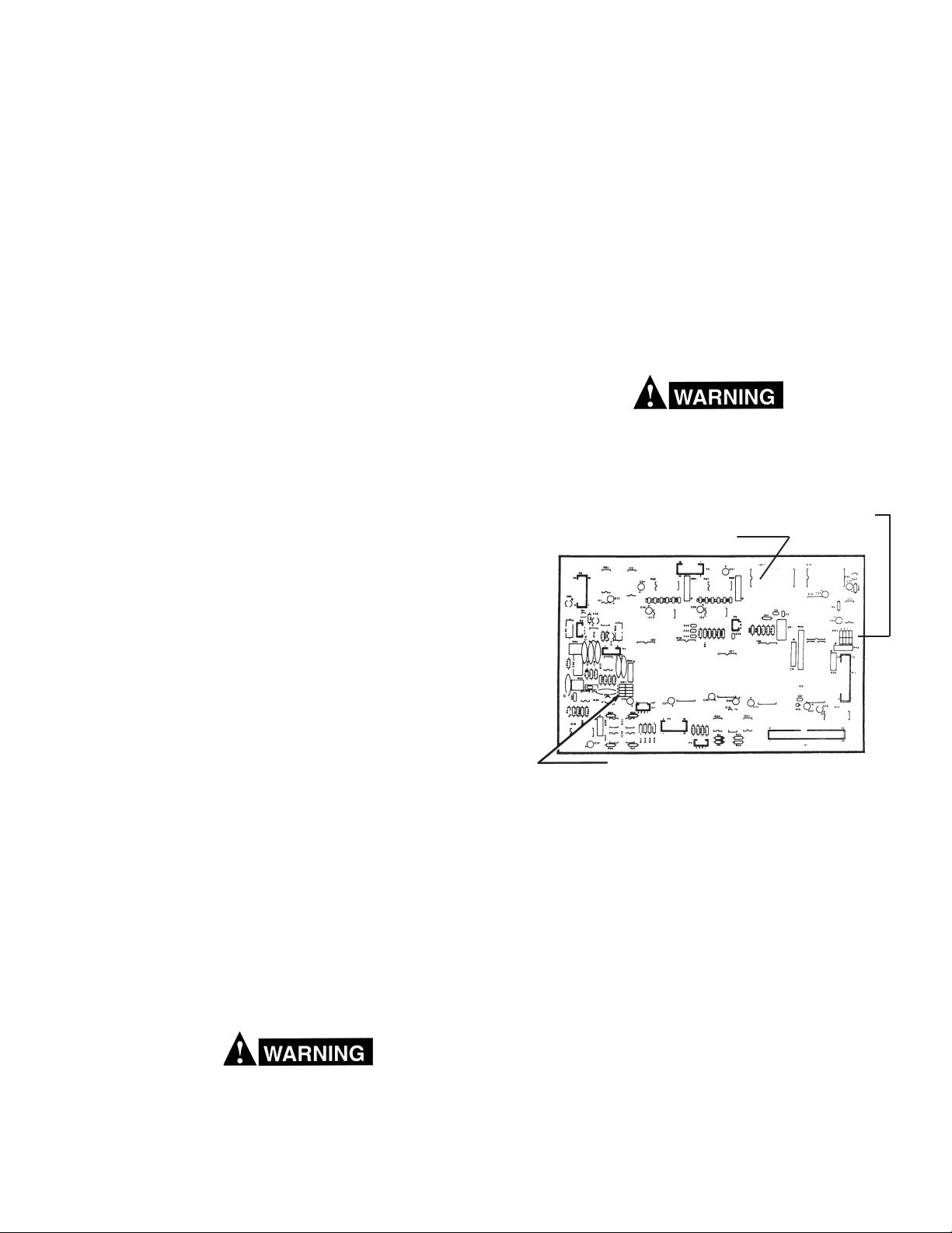
that has been preset for use-Pulse, Spray or Short arc.
Close the torch switch lever to energize and sequencein all of the selected process welding parameters. The
torch switch must be held closed throughout the operation unless you have activated the trigger-lock/crater-fill
function (see section IV-B-3A). The arc is established
when the welding wire touches the workpiece.
To stop welding (with no trigger-lock or crater-fill programmed), simply release the torch switch lever (do not
reactivate) and all functions will shutdown except auto
antistick and postflow. If trigger-lock or crater-fill is programmed, refer to section IV-B-3A for this function.
The system will also shutdown if preset wire speed or
arc voltage parameters cannot be maintained due to
abnormal (abort) conditions. If this occurs, the parameters causing the system shutdown will be signaled by a
flashing digital display and the welding sequence must
be restarted by actuating the RESET toggle switch.
After welding has been stopped, the control will always
recycle to the initial preset parameters of the selected
mode.
C. SPOT WELDING
If spot time is set, it is automatically programmed into all
welding conditions, i.e. short arc, spray and pulse. If this
feature is not desired, spot time must be set to zero. If
both spot time and trigger-lock are set, the trigger-lock
will be disregarded.
difference in potential that sends part of the welding
current through the safety ground wiring in the
control cable and wire feeder, resulting in burnout of
that wiring and/or damage to wire feeder circuitry. If
the safety ground burns out, the operator may be
exposed to 115V shock hazard.
Vll. MAINTENANCE
If this equipment does not operate properly stop work
immediately and investigate the cause of the malfunction. Maintenance work must be performed by an experienced person, and electrical work by a trained electrician. Do not permit untrained persons to inspect, clean,
or repair this equipment. Use only recommended replacement parts.
Be sure that the wall disconnect switch or circuit
breaker is open before attempting any inspection or
work on the inside of the power source or wire
feeder.
Location For "Dip" Sw. SW2
Location For Teach Option E-PROM
Close the torch switch to energize gas flow, weld contactor,
wire feed motor and start spot timing cycle. The torch
switch must be depressed during the entire weld period.
After the spotweld timing cycle is completed, all welding
action except auto-antistick or burnback and postflow
gas will stop automatically. Release the torch lever to
enable the next spot weld cycle.
D. SETTING/DISABLING SLOW RUN-IN FEATURE:
This feature allows the operator to have the wire feed
motor start at either full welding speed or half-speed, if
desired. Half speed starts may give better starts in some
cases. This feature works in all three processes. If half
speed is selected, the motor starts at half of the final
welding speed and jumps up to full speed once the arc is
established. To change this, remove the feeder cover
and locate the 4-position red rocker dip-switch on the
MPU pc board (see Figure 5). SW2-1 should be open for
half-speed run-in selection, and closed for fully speed
starts.
Do not allow metal-to-metal contact between the
wire feeder chassis and a metal surface connected
in any way to a welding ground. With such contact,
a poor welding ground connection may create a
Location For Dip Sw. SW1
Fig. 5 - MPU P.C. board
1. General Maintenance
Little maintenance is required to keep the wire feeder
in top operating condition. It is important, however,
that moving parts such as feed and pressure rolls,
wire feed motor, etc. be kept clean and free of dust or
dirt. Cleaning is best accomplished by regularly blowing off these parts with dry compressed air. This
should be done once for every eight hours of operating
time, more often if necessary.
2. Lubrication of Digital Motor-Gear Unit
The EH- 10A motor-gear digital unit is lubricated with
a heavy duty grease when assembled at the factory
and should not require further lubrication unless disassembled. If disassembled relubricate with Texaco
Multifak grease.
3. Check or Replacement of Motor Brushes.
Motor brushes should be checked periodically. If a
brush is broken, or worn down to less than 3/8-in.
19

length, it must be replaced. Brushes can be inspected
by unscrewing the brush-holder plug and withdrawing
the brush assembly. Never remove a brush without
matchmarking it and its holder, so that it can be
replaced in the same holder in its original position.
4. Removal of EH-10A Digital Welding Head
a. Unplug the control cables from the rear panel of the
wire feeder control.
b. Remove the accessory support assembly from the
motor-gear unit by loosening the capscrew at the
bottom of the assembly.
c. Disconnect the motor and tachometer cables from
terminal board (T1) inside the control assembly as
shown on the wiring diagram.
d. Remove the four screws which secure the digital
motor-gear unit to the base and remove the digital
unit.
Vlll. TROUBLESHOOTING
Be sure that all primary power to the machine has
been externally disconnected. Open wall disconnect
switch or circuit breaker before attempting inspection or work inside of the power source.
A. DIGIPULSE 450 POWER SOURCE
If power source is operating improperly, refer to the
troubleshooting information located in F-15-014.
B. DIGIPULSE WIRE FEEDER
Listed below are a number of trouble symptoms, each
followed by the checks or action suggested to determine
the cause. Listing of checks and/or actions is in most
probable order, but is not necessarily 100% exhaustive.
Always follow this general rule: Do not replace a printed
circuit (PC) board until you have made all the preceding
checks. Always put the power switch in off position
before removing or installing a PC board. Take great
care not to grasp or pull on components when removing
a PC board. Always place p.c. boards on a static free
surface. If a printed circuit (PC) board is determined to be
the problem, check with your supplier for a trade-in on a
new PC board. Supply the distributor with the part number of the PC board (and preprogram number, as described in step 1-c. following) as well as the serial number
of the wire feeder. Do not attempt to repair the PC board
yourself. Warranty on a PC board will be null and void if
repaired by customer or an unauthorized repair shop.
1. General
a. Check interconnection between control and power
source.
b. Energize the power source and the control.
c. Immediately after the control is turned on, a
number (e.g.:3) will appear in the IPM readout
window and will only be displayed for 1-second.
This number identifies the current program (EPROMS) used in your control. When a Program is
changed, the new E-PROMS will automatically
identify the new program number being used. If a
revision is made to an existing program a number
.1, .2, .3, etc. indicating the numerical revision will
also appear in the VOLTS readout window simultaneously.
d. After the one (l) second delay; the preset Weld
parameters will be displayed in the IPM and VOLTS
windows.
e. If the control is not functioning properly (or as
described above); for example, the numbers that
appear in one or both of the display windows are
meaningless (all zeros, eights, decimals, etc.), or
are completely incorrect in relation to your settings,
the memory must be cleared. This condition
might occur after a bad lightning storm, extremely
bad power line surges, etc. To clear the memory,
do the following:
(1) Place the Run-Set key switch in its SET posi-
tion.
(2) Turn off the units 110-volt Power switch.
(3) Using one hand, hold both of the Inc/Dec
toggle switches in their INC position while
reapplying 110-volt power with the other hand.
(4) Almost immediately after the Power has been
turned On, release the Inc/Dec toggle switches
to the neutral (spring-return center) position
and each of the windows should display one
zero, indicating a successful reset or clearing
has take place.
f. You can now enter the desired information as
described in this booklet.
2. No preset displays appear in windows.
a. Make sure the LED Display board harness/plug is
plugged into the P5 receptacle on the MPU board.
b. Check that 110 vac is available across terminals
T1-18 and T1- 19, if present;
c. Check for plus (+) 5 volts between terminals T1-11
and T1-12; if voltage is present, replace the MPU
board. If voltage is not present, check the voltage
regulator (VR) The voltage regulator is located on
the rear panel of the control box.
d. Check the input and output voltage of the regulator
VR.
(1) The input should be approx. 11 volts between
terminals T1-12 and VR-1. If voltage is not
present, replace I/O board.
(2) The output should be 5 volts between termi-
nals T1-12 and T1-11. If voltage is not present,
replace, voltage regulator
3. Preset display is provided, but cannot be varied.
a. Check normal setup procedures described in Sec-
tion V, then;
b. Make sure the key wiring harness plug is properly
connected to receptacle P6 on the MPU board, and
the lock-in key switch is placed in its SET position.
20
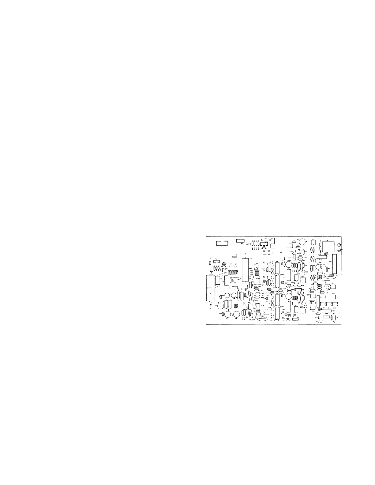
c. If neither of the above resolve the problem, replace
the MPU board.
4. Motor does not run.
a. Check to make sure all required (and/or optional)
accessories are correctly assembled as described
in Sect. III.
b. Make sure that power source is connected, plug P2
is securely connected to receptacle P2 on the
Digipulse I/0 Board, and then release the clapper
arm (pressure roll) on the Accessory Support Assembly.
(1) Operate the control INCH switch. If motor does
not run; replace the J governor board, and if
it still does not run, replace I/O and MPU
boards respectively.
(2) If the motor inches, but does not run when the
torch switch is operated (energized), check the
torch switch circuit components-switch, plug,
receptacle, etc. If motor still does not run,
check if power source is providing open-circuit
voltage to the control-if o.c.v. is not being
supplied, motor will not run. Check the power
source for trouble.
(3) Also check that the +/- 12 vdc are provided
from the power source on T1-10 and T1-8
respectively with respect to T1-9 (Com.).
(4) If power source if O.K., replace the I/O and
MPU boards respectively.
5. Motor runs, but not at right speed.
a. Check tachometer assembly mounted on the end
of the EH-10 wire feed motor.
b. Make sure the tach disc is securely fastened to the
motor shaft and that the strobe markings are not
scratched. Check that the disc is properly centered
in the strobe pickup on the p.c. board.
c. If all items in step b. are in order, and motor speed
is still incorrect, replace MPU board.
6. Arc VOLTS display reads zero after TS is operated.
a. Check that the 5-pin plug is securely connected to
the P3 receptacle on the MPU board.
b. If no reading is displayed, check for arc voltage
feedback between terminals TP1 and TP2 test
points on the l/O p.c. board (see Fig. 5A). This
voltage signal should correspond to that shown on
the power source voltmeter.
c. If voltage still reads zero, trace the voltage pickup
wiring from the power source to digipulse.
d. Remove the J-Gov p.c. board to gain access to the
P3 plug (harness) on the MPU p.c. board. Disconnect the P3 plug from its MPU board socket and,
using a meter check for +/- 12 volt power supply
output between plug pins P3-1 and P3-2 (for +12 v),
and between plug pins P3-4 and P3-2 (for - 12 v)
respectively. If voltage is present, replace MPU
board.
7. Control Shut-Down either preset VOLTS or IPM
displays will flash. The control will flash the parameter VOLTS or IPM that cannot be maintained.
These symptoms can occur if the preset conditions,
IPM or VOLTS, cannot be maintained by the control.
The speed (IPM) and voltage (VOLTS) conditions are
used to enhance arc starting in the adaptive mode of
operation. In the synergic mode, the voltage condition window will always display the number 100 and
cannot be adjusted; the speed condition, however,
can be checked and adjusted as described following.
To help determine which logic mode (adaptive or
synergic) the control is set to operate in, or how to
change it, please review Section VI-B.
a. IPM (speed) abort and possible causes:
(1) Initial hot start parameters incorrectly set. For
proper adjustment, refer to Set-up Procedures
following V-C-11.
(2) Defective J-governor board.
(3) Defective Motor tachometer board.
(4) Defective l/O board.
(5) Defective MPU board.
Contact ESAB Engineering Services for
further assistance. (803- 664-4416).
b. VOLTS (voltage) abort and possible causes:
This problem may be located in the wire feeder or
TP2
TP1
Fig. 5A - Input/Output (I/O) P. C. Board, P/N 674994
the power source. To determine this, check the
wire feeder as follows.
(1) Set the wire feeder for synergic operation in the
Pulse welding mode.
(2) Strike an arc and while welding, measure the
potential between T1-7 and T1-9 Note that as
the arc voltage setting is increased, the poten-
tial between T1-7 and T1-9 also increases, and
will range from 0 to 10 vdc. If it does not,
replace the l/O and/or MPU board. If the po-
tential is present and responding to the
voltage change setting, continue with step (3)
following.
21

(3) Now measure the control voltage, for the back-
ground current, between T1-9 and pin J1-J of
the amphenol connector. This measurement
can be taken without striking an arc. The potential will the be in a range from 1 to 2.5 volts.
If it is not, replace the I/O and/or MPU board.
If the background potential is present, con-
tinue with step (4) following.
(4) If both of the preceding conditions (steps 2 and
3) are okay, but the arc is still unsatisfactory,
the problem is either in the interconnecting
cable, the welding setup, or in the power source.
If possible, substitute a cable or power source
(known to be good) to check out the possible
problem; if these are not available, continue
with the wire feeder calibration test in step 8
following.
8. Erratic arc especially evident in the Pulse mode.
This could be caused by insufficient pulse height.
To check this, make the following calibration
test of the I/O board and power source.
To set up the control in the diagnostic mode, simultaneously depress the Wire Dia/Matl. key and hold the
IPM Inc/Dec key in its down position for 2.5 seconds
until a zero (0) appears in the IPM window. (The 2.5
seconds will prevent accidental zeroing of the Material
code.)
Now release both keys. The display windows will
change to show a BACKGROUND current value
(from 0 to 100) in the IPM window, and a PULSE
HEIGHT value (from 0.1 to 10) in the VOLTS window.
These numbers can be changed by their respective
INC/DEC switches.
To check the calibration of the l/O board, connect a
voltmeter from T1-9 (negative) to T1-7 (positive).
Energize the torch switch, and check the measured
voltage against the number displayed in the VOLTS
window they should both be the same (for example:
for a setting of 8.0, the measured potential should be
8 vdc.). If the measured potential is different, the l/O
board should either be recalibrated (by a qualified
technician) or the board should be replaced.
Next, check the potential from T1-9 (-) to pin J1- J of
the amphenol connector for a display of 40 in the IPM
window. The measured reading should be 2 vdc. If it
is not, replace the I/O board. If all of the readings are
correct, check the power source by using the calibration procedure described in Inverter Control Board
(lCB) Troubleshooting in the Power Source manual F15-014.
NOTE: Training and Troubleshooting Courses are avail-
able for maintenance and repair of this and other
equipment. For details, contact ESAB Welding
& Cutting Products, P.O. Box 100545, Florence,
SC 29501-0545; Telephone (803) 669-4411.
Attention: Technical Training Coordinator.
22
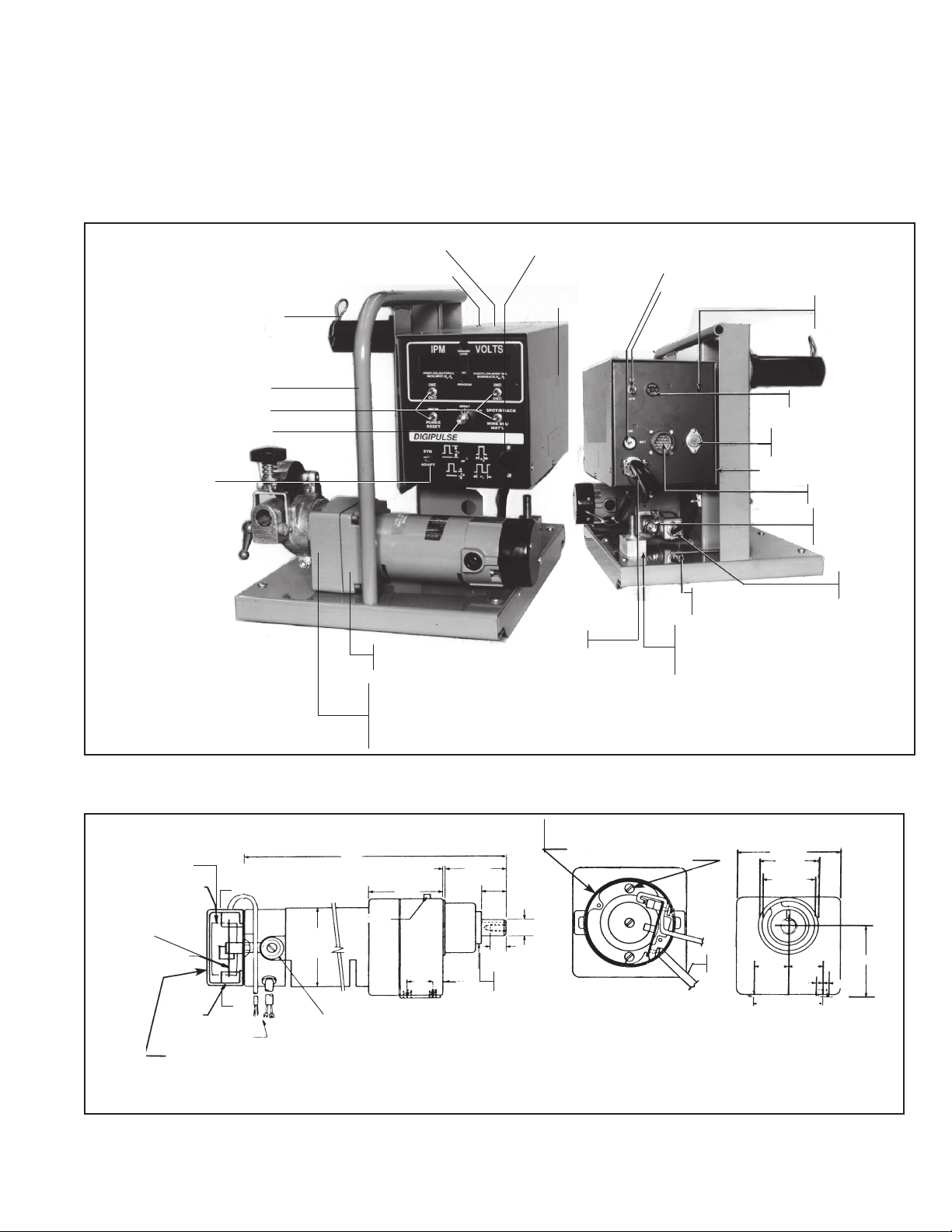
X. REPLACEMENT PARTS DATA
1. All replacement parts are keyed on the illustrations which follow. Order replacement parts by part number and
part name, as shown on illustrations. DO NOT ORDER BY PART NUMBER ALONE.
2. Always state the series or serial number of the machine on which the parts are to be used. The serial number
is stamped on the unit nameplate.
(SW1, 3, 5, 7) SWITCH - 950087
(SW 9) SWITCH 950492
TEACH SWITCH 950087 PART OF
OPT. TEACH KIT
P/N 35638
Not illustrated**
INSULATOR RING
60N90
KEY - 28N33
THUMBSCREW
61351087
FLATWASHER - 64309431
BELLWASHER - 950783
** FOR ACCESSORY
SUPPORT ASSY.
SPINDLE ASSY. 948259 (See Fig. 10)
BASE FRAME - 2075554
(SW 2) SWITCH -680359
KNOB - 951050
WARNING DECAL
- 2091514*
COVER - 30170*
EH-10A DIGITAL
MOTOR-GEAR UNIT
ASSY. - 679777 (See Fig. 7)
ACCESSORY SUPPORT
ASSYS:
2 ROLL DRIVE (Shown, See
Fig. 8) - 49V51
4 ROLL DRIVE (Not Shown,
See Suppl. L-12-821) - 600216
(J3) RECEPTACLE 182W64
WARNING DECAL
- 995204*
STRAIN RELIEF
96W76
KEYLOCK - 950956, REPLACEMENT KEY - 32778
(MLS) SWITCH 634517
(Ref.) OPENING FOR
POWER SUPPLY
LIFTING RING
POWER CABLE
ADAPTOR BLOCK - 674156
1/2-IN. - 13 STL. NUT
1/2-IN. LOCKWASHER
(2) 1/2-IN. FLATWASHER
CONTROL ASSY. (See Fig. 9)
TRIGGER LOCK
CRATER FILL SW
951059
(CB) CIRCUIT BREAKER 950874
VOLTAGE REGULATOR - 950159n
TRANSISTOR SOCKET - 950158
(C4) CAPACITOR - 995544
J1 RECEPTACLE - 950762
C20 CAPACITOR - 950265
GAS INLET CONN. 74S76
GAS OUTLET CONN. 58V58
(Front of Mtg. Plate)
n Recommended Spare
Parts
* Replace decal if it
becomes excessively
worn or lost or when
replacing panel(s) we
recommend that they
be inspected and if
necessary, replaced
(free of charge from 6
to 12 months.
(GSV) GAS
SOLENOID
VALVE -2062305
TACH, P.C. BD.
675429
(2) SCREW61324746
TACH DISK
950313
TACH COVER - 18787
(2) SCREWS #61324974
Fig. 7 - EH-10A Digital Motor-Gear Unit Assembly, W/54" Lug Cables (40:1), P/N 679777
Fig. 6 - Typical Digipulse Wire Feeder (All Models, Except As Noted)
TACH HOUSING - 18786
(2) #8 32 x 3/8" SCREW
.6251Ø
View AA
END VIEW
W/COVER REMOVED
Gear Case Lubricated with
Texaco Multifak Grease
Ø
A
A
Ø
(ref) 54" lg
11.6
VENT PLUG
3.25 Ø
2.875
.020
REF.
1.0
33
2.370
.93
50
D.P.
MIN.
LOCATING
COLLAR (REF)
FOR MOTOR REPLACEMENT PARTS - See Fig. 7A
23
MTR
LEAD
4.010 SQ.
2.25Ø
2.000
1.375 1.375
.25
5/16 - 18UNC 2B
63 MIN DEPTH
(11 full threads)
2.86
.25
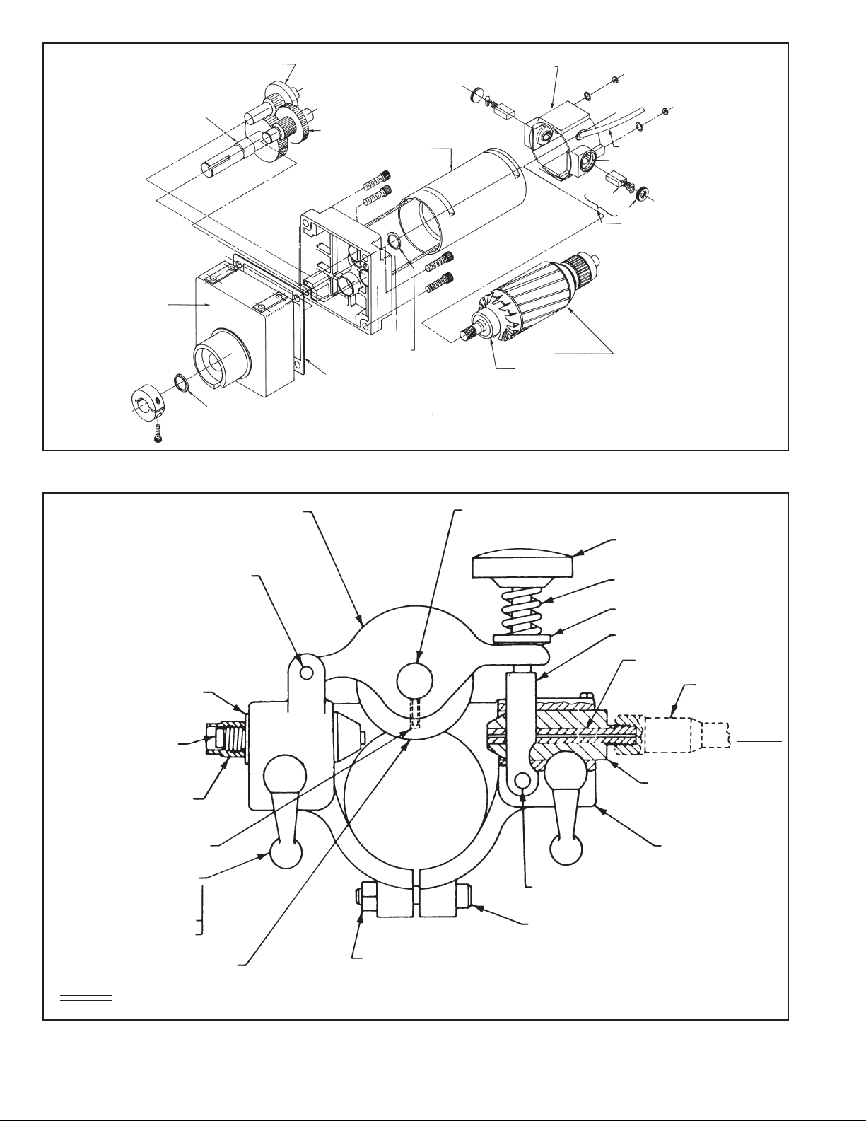
OUTPUT SHAFT ASSY. (Part of
19734 - OUTPUT GEAR CASE)
OUTPUT GEAR CASE
19734 (Includes
Output Shaft Assy.
Shown above)
GEAR ASSY. B - 20293
OUTPUT SHAFT SEAL
GEAR ASSY. A - 20292
MAGNET ASSY. - 19730
ARMATURE SHAFT SEAL
OUTPUT GEAR CASE GASKET
GASKET/SEAL KIT - 20542
(Includes those items
marked with )
BRUSH END BELL - 19732
(Includes TWO-BRUSH
HOLDER ASSYS.)
BRUSH
ARMATURE & BEARINGS 19726
Includes:
ARMATURE BEARING - 20288
Alternate gear sets* are available for the EH-10A motor.
50 1 Gear Set P/N 19211
17 1 Output Gear P/N 19210
NOTE: If an alternate gear set is used with a digital wire feed control an E-Prom
change is required in the control. Contact ESAB Welding & Cutting
Products Engineering Services in Florence, S.C.
Fig. 7A, EH-10A Motor-Gear Unit Parts Breakdown - 40:1 Gear Ratio
MOTOR CORD LEAD - 19731
BRUSH HOLDER
CAP
(2) CARBON BRUSH
REPLACEMENT KIT - 679784
Includes:
(2) BRUSH CAP
(2) CARBON BRUSH
ROLL PIN 1/4" x 1-3/4" LG
INLET
INLET WIRE GUIDE
29N13
INLET GUIDE INSERT
05N58
WIPER HOLDER*
598764
SET SCREW #6-32 x 1/4" LG
(61330849)
(2) LOCKING HANDLE
ASSEM - 49V44
(INCLUDES)
BOLT 1/4" x 1-5/8" LG
SPACER - 60N79
CLAPPER - 60N98
SHAFT - 60N65
KNOB - 60N68
LIGHT SPRING - 182W55 (FOR
SOFT 8 SMALL DIA. HARD WIRE)
RETAINER - 58N24
FORK - 49V43
ROLLPIN - 3/16" x 1-3/4" LG.
SCREW - 5/16" - 18 x 2" LG.
WIRE OUTLET GUIDE INSERT*
CONDUIT
OUTLET
WIRE OUTLET*
GUIDE
CLAMP -- 61N02
PRESSURE ROLL
28V52
SUPPLIED
HEAVY SPRING - 182W54 (FOR LARGE DIA. HARD WIRE)
Fig. 8 - Accessory Support Assembly, P/N 49V51
NUT - 5/16" - 18
* Outlet Guide And Wiper Holder Not Included In
Assembly Part No. 49V51
24
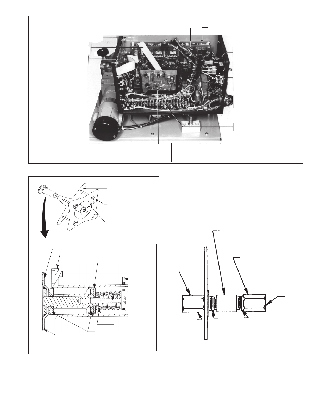
WARNING DECAL - 995164*
I/O-P4 To MPU-P2
CABLE ASSY. - 677938
DISPLAY P/C BOARD
ASSY. 675269
MPU P.C. BD. ASSY. - 18131
For 4.5 volt. Type 531 Replacement
Battery (on I/O Bd.). Order P/N 951733
(I/O) P.C. BOARD ASSY. - 674994n
(R1) RESISTOR 17240005 (25W, 5 Ohm)
(CTR2) CONTROL TRANSFORMER Assy. - 994303
(FN1) FILTER NETWORK
×
(CTR1) CONTROL
TRANSFORMER ASSY. - 950088
(T1) 20 PT. TERMINAL
STRIP - 950182
NOTE: The heat sinks on the J gov. board are
electrically hot.
Do NOT touch or ground while unit is energized
Fig. 9 - DIGIPULSE Control Assembly, P/N 30681 (ESAB); 35653 (L-TEC)
REEL
(4) .359" DIA. HOLE ON 3" DIA. D.C.
SPINDLE - 948258
WIRE REEL - 995570
Includes:
REEL - 995568
COVER - 995569
(4) WING NUT, 1/2" 13
63398183
(Ref. Hair Pin Clip)
D TYPE WASHER
948254
SCREW 5/16" 18 X 2"
HAIR PIN
CLIP 634347
J GOV. P.C. BOARDn
ASSY. - 994236 (See Note)
MTG. BRACKET - 995297
P.C. BOARD RECEPTACLE (P1) 636608
WATER
CONNECTION
58V75
(OUTLET)
COUPLING - 68121075
ADAPTOR - 11N16
(INLET)
n Recommended Spare Parts
* Replace decal if it becomes
excessively worn or lost.
SPRING - 948253
SUPPORT 948257
(2) BRAKE PAD - 948255
SPINDLE
Fig. 10 - Spindle Assembly, P/N 948259
Optional Wire Reel, P/N 995570
WASHER 948256
5/8-18 Lh
1/4 N.P.T.
WITHOUT SOLENOID VALVE
Fig. 11 - Water Kit without Solenoid Valve, P/N 994466
25
5/8-18 Lh

E
C
R
U
O
S
R
E
W
O
P
D-30682 (H)
Fig. 12 - Schematic Diagram - Digipulse XR and XRT (Except As Noted)
26

D-30683 (F)
Fig. 13A - Wiring Diagram - Digipulse
27

ESAB Welding & Cutting Products, Florence, SC Welding Equipment
COMMUNICATIONS GUIDE - CUSTOMER SERVICES
A. CUSTOMER SERVICE QUESTIONS: Telephone (803) 664-5540/Fax: (800) 634-7548
Order Entry Product Availability Pricing Hours: 8:30 AM to 5:00 PM EST
Order Changes Saleable Goods Returns Delivery
Shipping Information
B. ENGINEERING SERVICE: Telephone: (803) 664-4416 / Fax : (800) 446-5693
Welding Equipment Troubleshooting Hours: 7:30 AM to 5:00 PM EST
Warranty Returns Authorized Repair Stations
C. TECHNICAL SERVICE: Telephone: (800) ESAB-123/ Fax: (803) 664-4452
Part Numbers Technical Applications Hours: 8:00 AM to 5:00 PM EST
Performance Features Technical Specifications Equipment Recommendations
D. LITERATURE REQUESTS: Telephone: (803) 664-5501 / Fax: (803) 664-5548
E. WELDING EQUIPMENT REPAIRS: Telephone: (803) 664-4469 / Fax: (803) 664-5557
Repair Estimates Repair Status Hours: 7:30 AM to 3:30 PM EST
F. WELDING EQUIPMENT TRAINING:
Telephone: (803)664-4428 / Fax: (803) 664-4476
Training School Information and Registrations Hours: 7:30 AM to 4:00 PM EST
G. WELDING PROCESS ASSISTANCE:
Telephone: (803) 664-4248 / Fax: (803) 664-4454 Hours: 7:30 AM to 4:00 PM EST
H. TECHNICAL ASST. CONSUMABLES:
Telephone: (800) 934-9353 Hours: 7:30 AM to 5:00 PM EST
Hours: 7:30 AM to 4:00 PM EST
IF YOU DO NOT KNOW WHOM TO CALL
Telephone: (800) ESAB-123/ Fax: (803) 664-4452/Web: http://www.esab.com
Hours: 7:30 AM to 5:00 PM EST
F-15-012-B 11/96 Printed in U.S.A.
 Loading...