

Page 1

INSTRUCTIONS for
DIGIPULSE DUAL
F-15-496-A
May, 1999
WIRE FEEDER
Bombardier
P/N 33299
These INSTRUCTIONS are for experienced operators. If you are not fully familiar with the principles of operation and safe practices
for arc welding equipment we urge you to read our booklet Precautions and Safe Practices for Arc Welding, Cutting and Gouging, Form
52-529. Do NOT permit untrained persons to install, operate or maintain this equipment. Do NOT attempt to install or operate this
equipment until you have read and fully understand these instructions. If you do not fully understand these instructions contact your
supplier for further information. Be sure to read the Safety Precautions on page 2 before installing or operating this equipment.
Be sure this information reaches the operator.
You can get extra copies through your supplier.
Page 2

USER RESPONSIBILITY
This equipment will perform in conformity with the description thereof contained in this manual and accompanying labels
and/or inserts when installed, operated, maintained and repaired in accordance with the instructions provided. This
equipment must be checked periodically. Malfunctioning or poorly maintained equipment should not be used. Parts
that are broken, missing, worn, distorted or contaminated should be replaced immediately. Should such repair or
replacement become necessary, the manufacturer recommends that a telephone or written request for service advice
be made to the Authorized Distributor from whom purchased.
This equipment or any of its parts should not be altered without the prior written approval of the manufacturer. The user
of this equipment shall have the sole responsibility for any malfunction which results from improper use, faulty
maintenance, damage, improper repair or alteration by anyone other than the manufacturer or a service facility
designated by the manufacturer.
TABLE OF CONTENTS
SECTION TITLE PAGE
PARAGRAPH
SAFETY PRECAUTIONS .......................................................................................................................... 3
SECTION 1 DESCRIPTION ................................................................................................. 7
SECTION 2 INSTALLATION ................................................................................................ 12
SECTION 3 OPERATION ..................................................................................................... 16
SECTION 4 MAINTENANCE ................................................................................................ 19
SECTION 5 REPLACEMENT PARTS .................................................................................. 22
2
Page 3

SAFETY PRECAUTIONS
WARNING: These Safety Precautions are for
your protection. They summarize precautionary information from the references listed in
Additional Safety Information section. Before
performing any installation or operating procedures, be
sure to read and follow the safety precautions listed below
as well as all other manuals, material safety data sheets,
labels, etc. Failure to observe Safety Precautions can result
in injury or death.
PROTECT YOURSELF AND OTHERS --
Some welding, cutting, and gouging
processes are noisy and require ear
protection. The arc, like the sun, emits
ultraviolet (UV) and other radiation and
can injure skin and eyes. Hot metal can cause burns.
Training in the proper use of the processes and equipment is essential to prevent accidents. Therefore:
1. Always wear safety glasses with side shields in any work
area, even if welding helmets, face shields, and goggles
are also required.
2. Use a face shield fitted with the correct filter and cover
plates to protect your eyes, face, neck, and ears from
sparks and rays of the arc when operating or observing
operations. Warn bystanders not to watch the arc and
not to expose themselves to the rays of the electric-arc
or hot metal.
3. Wear flameproof gauntlet type gloves, heavy long-sleeve
shirt, cuffless trousers, high-topped shoes, and a welding helmet or cap for hair protection, to protect against
arc rays and hot sparks or hot metal. A flameproof apron
may also be desirable as protection against radiated
heat and sparks.
4. Hot sparks or metal can lodge in rolled up sleeves,
trouser cuffs, or pockets. Sleeves and collars should be
kept buttoned, and open pockets eliminated from the
front of clothing
5. Protect other personnel from arc rays and hot sparks
with a suitable non-flammable partition or curtains.
6. Use goggles over safety glasses when chipping slag or
grinding. Chipped slag may be hot and can fly far.
Bystanders should also wear goggles over safety glasses.
FIRES AND EXPLOSIONS -- Heat from
flames and arcs can start fires. Hot slag
or sparks can also cause fires and explosions. Therefore:
1. Remove all combustible materials well away from the
work area or cover the materials with a protective nonflammable covering. Combustible materials include wood,
cloth, sawdust, liquid and gas fuels, solvents, paints and
coatings, paper, etc.
2. Hot sparks or hot metal can fall through cracks or
crevices in floors or wall openings and cause a hidden
smoldering fire or fires on the floor below. Make certain
that such openings are protected from hot sparks and
metal.“
3. Do not weld, cut or perform other hot work until the
workpiece has been completely cleaned so that there
are no substances on the workpiece which might produce flammable or toxic vapors. Do not do hot work on
closed containers. They may explode.
4. Have fire extinguishing equipment handy for instant use,
such as a garden hose, water pail, sand bucket, or
portable fire extinguisher. Be sure you are trained in its
use.
5. Do not use equipment beyond its ratings. For example,
overloaded welding cable can overheat and create a fire
hazard.
6. After completing operations, inspect the work area to
make certain there are no hot sparks or hot metal which
could cause a later fire. Use fire watchers when necessary.
7. For additional information, refer to NFPA Standard 51B,
"Fire Prevention in Use of Cutting and Welding Processes", available from the National Fire Protection Association, Batterymarch Park, Quincy, MA 02269.
ELECTRICAL SHOCK -- Contact with live
electrical parts and ground can cause
severe injury or death. DO NOT use AC
welding current in damp areas, if movement is confined, or if there is danger of
falling.
1. Be sure the power source frame (chassis) is connected
to the ground system of the input power.
2. Connect the workpiece to a good electrical ground.
3. Connect the work cable to the workpiece. A poor or
missing connection can expose you or others to a fatal
shock.
4. Use well-maintained equipment. Replace worn or damaged cables.
5. Keep everything dry, including clothing, work area,
cables, torch/electrode holder, and power source.
6. Make sure that all parts of your body are insulated from
work and from ground.
7. Do not stand directly on metal or the earth while working
in tight quarters or a damp area; stand on dry boards or
an insulating platform and wear rubber-soled shoes.
8. Put on dry, hole-free gloves before turning on the power.
9. Turn off the power before removing your gloves.
10. Refer to ANSI/ASC Standard Z49.1 (listed on next page)
for specific grounding recommendations. Do not mistake the work lead for a ground cable.
ELECTRIC AND MAGNETIC FIELDS —
May be dangerous. Electric current flowing through any conductor causes localized Electric and Magnetic Fields
(EMF). Welding and cutting current creates EMF around welding cables and
welding machines. Therefore:
1. Welders having pacemakers should consult their physician before welding. EMF may interfere with some pacemakers.
2. Exposure to EMF may have other health effects which are
unknown.
3. Welders should use the following procedures to minimize
exposure to EMF:
A. Route the electrode and work cables together. Secure
them with tape when possible.
B. Never coil the torch or work cable around your body.
C. Do not place your body between the torch and work
cables. Route cables on the same side of your body.
D. Connect the work cable to the workpiece as close as
possible to the area being welded.
E. Keep welding power source and cables as far away
from your body as possible.
10/98
3
Page 4

FUMES AND GASES -- Fumes and
gases, can cause discomfort or harm,
particularly in confined spaces. Do
not breathe fumes and gases. Shielding gases can cause asphyxiation.
Therefore:
1. Always provide adequate ventilation in the work area by
natural or mechanical means. Do not weld, cut, or gouge
on materials such as galvanized steel, stainless steel,
copper, zinc, lead, beryllium, or cadmium unless positive mechanical ventilation is provided. Do not breathe
fumes from these materials.
2. Do not operate near degreasing and spraying operations. The heat or arc rays can react with chlorinated
hydrocarbon vapors to form phosgene, a highly toxic
gas, and other irritant gases.
3. If you develop momentary eye, nose, or throat irritation
while operating, this is an indication that ventilation is not
adequate. Stop work and take necessary steps to improve ventilation in the work area. Do not continue to
operate if physical discomfort persists.
4. Refer to ANSI/ASC Standard Z49.1 (see listing below)
for specific ventilation recommendations.
5. WARNING: This product, when used for welding or
cutting, produces fumes or gases which
contain chemicals known to the State of
California to cause birth defects and, in
some cases, cancer. (California Health &
Safety Code
CYLINDER HANDLING -- Cylinders, if
mishandled, can rupture and violently
release gas. Sudden rupture of cylinder, valve, or relief device can injure or
kill. Therefore:
1. Use the proper gas for the process and use the proper
pressure reducing regulator designed to operate from
the compressed gas cylinder. Do not use adaptors.
Maintain hoses and fittings in good condition. Follow
manufacturer's operating instructions for mounting regulator to a compressed gas cylinder.
2. Always secure cylinders in an upright position by chain
or strap to suitable hand trucks, undercarriages, benches,
walls, post, or racks. Never secure cylinders to work
tables or fixtures where they may become part of an
electrical circuit.
3. When not in use, keep cylinder valves closed. Have
valve protection cap in place if regulator is not connected. Secure and move cylinders by using suitable
hand trucks. Avoid rough handling of cylinders.
4. Locate cylinders away from heat, sparks, and flames.
Never strike an arc on a cylinder.
5. For additional information, refer to CGA Standard P-1,
"Precautions for Safe Handling of Compressed Gases in
Cylinders", which is available from Compressed Gas
Association, 1235 Jefferson Davis Highway, Arlington,
VA 22202.
§25249.5 et seq.)
EQUIPMENT MAINTENANCE -- Faulty or
improperly maintained equipment can
cause injury or death. Therefore:
1. Always have qualified personnel perform the installation, troubleshooting, and maintenance work. Do not
perform any electrical work unless you are qualified to
perform such work.
2. Before performing any maintenance work inside a power
source, disconnect the power source from the incoming
electrical power.
3. Maintain cables, grounding wire, connections, power
cord, and power supply in safe working order. Do not
operate any equipment in faulty condition.
4. Do not abuse any equipment or accessories. Keep
equipment away from heat sources such as furnaces,
wet conditions such as water puddles, oil or grease,
corrosive atmospheres and inclement weather.
5. Keep all safety devices and cabinet covers in position
and in good repair.
6. Use equipment only for its intended purpose. Do not
modify it in any manner.
ADDITIONAL SAFETY INFORMATION -- For
more information on safe practices for electric arc welding and cutting equipment, ask
your supplier for a copy of "Precautions and
Safe Practices for Arc Welding, Cutting and
Gouging", Form 52-529.
The following publications, which are available from the
American Welding Society, 550 N.W. LeJuene Road, Miami, FL 33126, are recommended to you:
1. ANSI/ASC Z49.1 - "Safety in Welding and Cutting"
2. AWS C5.1 - "Recommended Practices for Plasma Arc
Welding"
3. AWS C5.2 - "Recommended Practices for Plasma Arc
Cutting"
4. AWS C5.3 - "Recommended Practices for Air Carbon
Arc Gouging and Cutting"
5. AWS C5.5 - "Recommended Practices for Gas Tungsten
Arc Welding“
6. AWS C5.6 - "Recommended Practices for Gas Metal Arc
Welding"“
7. AWS SP - "Safe Practices" - Reprint, Welding Handbook.
8. ANSI/AWS F4.1, "Recommended Safe Practices for
Welding and Cutting of Containers That Have Held
Hazardous Substances."
MEANING OF SYMBOLS - As used throughout this manual: Means Attention! Be Alert!
Your safety is involved.
Means immediate hazards which, if
not avoided, will result in immediate,
serious personal injury or loss of life.
Means potential hazards which could
result in personal injury or loss of life.
Means hazards which could result in
minor personal injury.
4
SP98-10
Page 5

PRÉCAUTIONS DE SÉCURITÉ
AVERTISSEMENT: Ces règles de sécurité ont pour objet
d’ assurer votre protection. Veillez à lire et à observer les
précautions énoncées ci-dessous avant de monter l’
équipement ou de commercer à l’utiliser. Tout défaut
d’observation de ces précautions risque d’entraîner des
blessures graves ou mortelles.
1. PROTECTION INDIVIDUELLE-- Les brûlures de la
peau et des yeux dues au rayonnement de l’arc
électrique ou du métal incandescent, lors du soudage
au plasma ou à l’électrode ou lors du gougeage à
l’arc, peuvent s’avérer plus graves que celles résultant
d’une exposition prolongée au soleil. Aussi convient-il
d’observer les précautions suivantes:
a. Portez un écran facial adéquat muni des plaques
protectrices et des verres filtrants appropriés afin de
vous protéger les yeux, le visage, le cou et les oreilles
des étincelles et du rayonnement de l’arc électrique
lorsque vous effectuez des soudures ou des coupes
ou lorsque vous en observez l’exécution.
AVERTISSEZ les personnes se trouvant à proximité
de façon à ce qu’elles ne regardent pas l’arc et à ce
qu’elles ne s’exposent pas à son rayonnement, ni à
celui du métal incandescent.
b. Portez des gants ignifugés à crispins, une tunique
épaisse à manches longues, des pantalons sans
rebord, des chaussures à embout d’acier et un
casque de soudage ou une calotte de protection, afin
d’éviter d’exposer la peau au rayonnement de l’arc
électrique ou du métal incandescent. ll est également
souhaitable d’utiliser un tablier ininflammable de
façon à se protéger des étincelles et du rayonnement
thermique.
c. Les étincelles ou les projections de métal incandescent
risquent de se loger dans des manches retroussées,
des bords relevés de pantalons ou dans des poches.
Aussi convient-il de garder boutonnés le col et les
manches et de porter des vêtements sans poches à
l’avant.
d. Protégez des étincelles et du rayonnement de l’arc
électrique les autres personnes travaillant à proximité
à l’aide d’un écran ininflammable adéquat.
e. Ne jamais omettre de porter des lunettes de sécurité
lorsque vous vous trouvez dans un secteur où l’on
effectue des opérations de soudage ou de coupage à
l’arc. Utilisez des lunettes de sécurité à écrans ou
verres latéraux pour piquer ou meûler le laitier. Les
piquetures incandescentes de laitier peuvent être
projetées à des distances considérables. Les
personnes se trouvant à proximité doivent également
porter des lunettes de protection.
f. Le gougeage à l’arc et le soudage à l’arc au plasma
produisent un niveau de bruit extrêmement élevé (de
100 à 114 dB) et exigent par conséquent l’emploi de
dispositifs appropriés de protection auditive.
2. PRÉVENTION DES INCENDES-- Les projections de
laitier incandescent ou d’étincelles peuvent
provoquer de graves incendies au contact de
matériaux combustibles solides, liquides ou gazeux.
Aussi faut-il observer les précautions suivantes:
a. Éloigner suffisamment tous les matériaux combustibles
du secteur où l’on exécute des soudures ou des
coupes à l’arc, à moins de les recouvrir complètement
d’une bâche non-inflammable. Ce type de matériaux
comprend notamment le bois, les vêtements, la sciure,
l’essence, le kérosène, les peintures, les solvants, le
gaz naturel, l’acétylène, le propane et autres substances combustibles semblables.
b. Les étincelles ou les projections de métal incandescent
peuvent tomber dans des fissures du plancher ou dans
des ouvertures des murs et y déclencher une ignition
lente cachée. Veiller à protéger ces ouvertures des
étincelles et des projections de métal.
c. N’exécutez pas de soudures, de coupes, d’opérations
de gougeage ou autres travaux à chaud à la surface
de barils, bidons, réservoirs ou autres contenants
usagés, avant de les avoir nettoyés de toute trace de
substance susceptible de produire des vapeurs
inflammables ou toxiques.
d. En vue d’assurer la prévention des incendies, il
convient de disposer d’un matériel d’extinction prêt à
servir immédiatement, tel qu’un tuyau d’arrosage, un
seau à eau, un seau de sable ou un extincteur portatif.
e. Une fois le travail à l’arc terminé, inspectez le secteur
de façon à vous assurer qu’aucune étincelle ou projection de métal incandescent ne risque de provoquer
ultérieurement un feu.
3. CHOC ÉLECTRIQUE-- Le gougeage à l’arc et à l’arc
au plasma exige l’emploi de tensions à vide
relativement importantes; or, celles-ci risquent de
causer des dommages corporels graves et même
mortels en cas d’utilisation inadéquate. La gravité du
choc électrique reçu dépend du chemin suivi par le
courant à travers le corps humain et de son intensité.
a. Ne laissez jamais de surfaces métalliques sous tension
venir au contact direct de la peau ou de vêtements
humides. Veillez à porter des gants bien secs.
b. Si vous devez effectuer un travail sur une surface
métallique ou dans un secteur humide, veillez à assurer votre isolation corporelle en portant des gants secs
et des chaussures à semelles de caoutchouc et en
vous tenant sur une planche ou une plate-forme
sèche.
c. Mettez toujours à la terre le poste de soudage/coupage
en le reliant par un câble à une bonne prise de terre.
d. N’utilisez jamais de câbles usés ou endommagés. Ne
surchargez jamais le câble. Utilisez toujours un
équipement correctement entretenu.
e. Mettez l’équipement hors tension lorsqu’il n’est pas en
service. une mise à la masse accidentelle peut en effet
provoquer une surchauffe de l’équipement et un danger d’incendie. Ne pas enrouler ou passer le câble
autour d’une partie quelconque du corps.
f. Vérifiez si le câble de masse est bien relié à la pièce en
un point aussi proche que possible de la zone de
travail. Le branchement des câbles de masse à
l’ossature du bâtiment ou en un point éloigné de la
zone de travail augmente en effet le risque de
passage d’un courant de sortie par des chaînes de
9/97
5
Page 6

levage, des câbles de grue ou divers chemins
électriques.
g. Empêchez l’apparition de toute humidité, notamment
sur vos vêtements, à la surface de l’emplacement de
travail, des câbles, du porte-électrode et du poste de
soudage/coupage. Réparez immédiatement toute
fuite d’eau.
4. VENTILATION-- La respiration prolongée des fumées
résultant des opérations de soudage/coupage, à
l’intérieur, d’un local clos, peut provoquer des malaises et des dommages corporels. Aussi convient-il
d’observer les précautions suivantes:
a. Assurez en permanence une aération adéquate de
l’emplacement de travail en maintenant une ventilation naturelle ou à l’aide de moyens mécaniques.
N’effectuez jamais de travaux de soudage ou de
coupage sur des matériaux de zinc, de plomb, de
beryllium ou de cadmium en l’absence de moyens
mécaniques de ventilation capables d’empêcher
l’inhalation des fumées dégagées par ces matériaux.
b. N’effectuez jamais de travaux de soudage ou de
coupage à proximité de vapeurs d’hydrocarbure
chloré résultant d’opérations voisines de dégraissage
ou de pulvérisation. La chaleur dégagée ou le
rayonnement de l’arc peut déclencher la formation de
phosgène -- gaz particulièrement toxique -- et d’autres
gaz irritants, à partir des vapeurs de solvant.
c. Une irritation momentanée des yeux, du nez ou de la
gorge constatée au cours de l’utilisation de
l’équipement dénote un défaut de ventilation. Arrêtezvous de travailler afin de prendre les mesures nécessaires à l’amélioration de la ventilation. Ne poursuivez
pas l’opération entreprise si le malaise persiste.
d. Certaines commandes comportent des canalisations
où circule de l’hydrogène. L’armoire de commande est
munie d’un ventilateur destiné à empêcher la formation de poches d’hydrogène, lesquelles présentent un
danger d’explosion; ce ventilateur ne fonctionne que si
l’interrupteur correspondant du panneau avant se
trouve placé en position ON (Marche). Veillez à
manœuvrer cette commande en vérifiant si le
couvercle est bien en place, de façon à assurer
l’efficacité de la ventilation ainsi réalisée. Ne jamais
débrancher le ventilateur.
e. Les fumées produites par l’opération de soudage ou
de coupage peuvent s’avérer toxiques. Aussi est-il
nécessaire de disposer en permanence d’un dispositif
adéquat de ventilation de type aspirant, afin d’éliminer du voisinage de l’opérateur tout dégagement de
fumée visible.
f. Consultez les recommandations particulières en
matière de ventilation indiquées à l’alinéa 6 de la
norme Z49.1 de l’AWS.
5. ENTRETIEN DE L’ÉQUIPEMENT-- Un équipement
entretenu de façon défectueuse ou inadéquate risque
non seulement de réaliser un travail de mauvaise
qualité mais, chose plus grave encore, d’entraîner des
dommages corporels graves, voire mortels en
déclenchant des incendies ou des chocs électriques.
Observez par conséquent les précautions suivantes:
a. Efforcez-vous de toujours confier à un personnel qua-
lifié l’installation, le dépannage et l’entretien du poste
de soudage et de coupage. N’effectuez aucune
réparation électrique sur l’équipement à moins d’être
qua-lifié à cet effet.
b. Ne procédez jamais à une tâche d’entretien
quelconque à l’intérieur du poste de soudage/
coupage, avant d’avoir débranché l’alimentation
électrique.
c. Maintenez en bon état de fonctionnement les câbles,
le câble de masse, les branchements, le cordon
d’alimentation et le poste de soudage/coupage.
N’utilisez jamais le poste ou l’équipement s’il présente
une défectuosité quelconque.
d. Prenez soin du poste de soudage et de coupage et des
équipements accessoires. Gardez-les à l’écart des
sources de charleur, notamment des fours, de
l’humidité, des flaques d’eau maintenez-les à l’abri des
traces d’huile ou de graisse, des atmosphères corrosives et des intempéries.
e. Laissez en place tous les dispositifs de sécurité et tous
les panneaux de l’armoire de commande en veillant à
les garder en bon état.
f. Utilisez le poste de soudage/coupage conformément à
son usage prévu et n’effectuez aucune modification.
6. INFORMA TIONS COMPLÉMENT AIRES RELATIVES À
LA SÉCURITÉ--
Pour obtenir des informations complémentaires sur les
règles de sécurité à observer pour le montage et
l’utilisation d’équipements de soudage et de coupage
électriques et sur les méthodes de travail
recommandées, demandez un exemplaire du livret N°
52529 “Precautions and Safe Practices for Arc Welding, Cutting and Gouging” publié par ESAB. Nous
conseillons également de consulter les publications
sui-vantes, tenues à votre disposition par l’American
Welding Society, 550 N.W. LeJuene Road, Miami, FL
32126:
a. “Safety in Welding and Cutting” AWS Z49.1
b. “Recommended Safe Practices for Gas-Shielded Arc
Welding “AWS A6. 1.
c. “Safe Practices for Welding and Cutting Containers
That Have Held Combustibles” AWS-A6.0.
d. “Recommended Safe Practices for Plasma Arc Cutting”
AWS-A6. 3.
e. “Recommended Safe Practices for Plasma Arc Weld-
ing” AWS-C5. 1.
f. “Recommended Safe Practices for Air Carbon Arc
Gouging and Cutting” AWS-C5. 3.
g. “Code For Safety in Welding and Cutting”
CSA-Standard W117. 2.
9/97
6
Page 7

SECTION I DESCRIPTION
SPECIFICATIONS
Input Power Required....................... 115 volts 50/60 Hz single phase Wire
Feed Speed Range ................................... 20-999 in./min. (.5-26.4 m/min.)
Wire Sizes Accommodated:
Hard/Soft ............................................. .023 thru 1/8-in. (.6 thru 3.2 mm)
Flux Cored ......................................... .035 thru 1/8-in. (0.9 thru 3.2 mm)
Length ................................................................................ 24-in. (610 mm)
Width ............................................................................ 22-1/2-in. (572 mm)
Height ................................................................................. 15-in. (381 mm)
Weight (less wire) .................................................................. 80-lbs. (36 kg)
LEFT DIGITAL READOUT (IPM)
LEFT INC-DEC TOGGLE
INCH/GAS PURGE
RESET SELECTOR
CRATER SELECTOR SW.
INTRODUCTION
This Digipulse Dual wire feeder is designed as a dual
torch welder with each torch capable of furnishing eight
completely different sets of welding parametersin
other words, sixteen (16) completely different welding
schedules can be preset to meet the requirements of
high production shops. The standard Dual control features include presettable wire feed speed (ipm), voltage, pre and postflow gas shielding, cold wire inching,
gas purging, adaptive or manual burnback, spot welding timer and crater fill functions.
SPINDLE ASSY.
RIGHT DIGITAL READOUT (VOLT)
RIGHT INC-DEC TOGGLE
SPOT/BACK-SELECT SWITCH
RIGHT TORCH RECPT.
LEFT TORCH ACCY.
SUPPORT ASSY.
& EH-10 MOTOR
GEAR TACH UNIT
RESET CIRCUIT BREAKER
POWER ON-OFF SW.
RUN-SET KEY SW.
LEFT TORCH RECEPT.
TORCH ACCY. RIGHT
SUPPORT ASSY.
& EH-10 MOTOR-GEAR-TACH UNIT
J1 CONTROL RECPT.
LEFT TORCH GAS SOL
CONNECTION
RIGHT TORCH GAS
SOL CONNECTION
LOCATION FOR OPT.
WATER CONNECTIONS
Fig. 1 - Digipulse Dual Feeder
POWER CABLE
ADAPTOR BLOCK
7
Page 8

SECTION I DESCRIPTION
A. STANDARD FEATURES/BENEFITS
n microprocessor accuracy the microprocessor, the
controlling "brain" of the Digipulse Dual, operates
exclusively on drift free digital logic. The digital logic
delivers extraordinarily precise computer-accurate
weld parameter control and weld consistency.
n microprocessor flexibility the Digipulse incorpo-
rates electronically reprogrammable modules; by simply reprogramming this small plug-in module many
existing functions may be extended or new features
maybe added.
n microprocessor reliability ESABs Digipulse Dual
Wire Feeders have proven to be rugged and reliable
in test after test for absolute minimum downtime.
n presettable wire feed speed (Ipm) and voltage (volts)
provides ability to easily and accurately preset the
exact welding parameters desired before the welding
sequence begins.
n patented microprocessor controlled closed loop sys-
tems provides most accurate means of maintaining
wire feed speed (amperage) and welding voltage; the
microprocessor compensates for deviations in ambient temperature primary voltage fluctuation and
changes in arc dynamics or wire feed force conditions,
to assure that preset parameters are maintained.
n sure start interlock to assure trouble free starts the
Digipulse Dual has an interlock circuit which will not
allow wire feed to initiate when the torch trigger Is
pulled unless the power supply contactor is closed
and voltage is present; the cold wire INCH, however,
will be operative at all times.
n individual digital LED meters provide large 1/2-in.
readout of voltage and wire feed speed continuous
display of preset and then actual welding voltage and
wire feed speed for accurate observation.
n automatic "shut down" assures welding is done at
the preset parameters; unit automatically shuts down,
if for any reason either the volts or ipm cannot be
maintained for a preprogrammed time period; simultaneously, cause is indicated by flashing digital display.
n toggle switch adjustment of weld parameters by fine
increments or rapid coarse adjustment allows
quick, easy, and accurate adjustments of welding
parameters.
n gas pre and postflow and cold wire inch capability
gas pre and postflow provides independent adjustment in tenths of a second for highest weld quality and
economy; cold wire inch speed can be independently
adjusted from welding wire feed speed to reduce
downtime.
n eight schedule capability per torchenables operator
to have two different sets of weld parameters (for each
torch) at his fingertips. The microprocessor allows the
operator to change schedules with a simple clickclick squeeze of the torch trigger switch to be used.
n automatic adaptive anti-stick or manual burnback
time featurea patented adaptive anti-stick circuit
automatically adjusts the same amount of wire
burnback regardless of wire size, speed or voltage; or,
you can manually preset a BurnbackTime to specifically suit a specialized application; the manual burnback
function (programmed up to 30 cycles in the VOLTS
window) allows you to override the automatic adaptive
anti-stick by setting a specific burnback time.
n spot weld timerbecause the spot weld timer is
adjustable up to 999 cycles (16.5 sec.) in the IPM
window, it is more than a conventional spot feature;
it is also a weld timer extending its use for Increment
or Stitch welding.
n the Crater Fill feature allows the operator to preset a
special welding wire feed speed (IPM), arc length
(VOLTS) and time (TIMES) to control the shape and
size of the weld crater upon termination of the welding process.
n circuit protectionresettable circuit breaker for input
power minimizes downtime and maintenance.
n EH-10A permanent magnet motorsprovide the high-
est torque, fastest response, and best efficiency of
any mig p.m. motor on the market.
n patented closed loop J governor/optical tachom-
eterprovides most accurate means of maintaining
wire feed speed and voltage, regardless of any voltage drop or drift.
8
Page 9

SECTION I DESCRIPTION
I. DESCRIPTION
II. REQUIRED EQUIPMENT
The Digipulse Dual torch welder is a microprocessor
controlled digital wire feeder designed for mig short arc/
spray and pulse arc welding applications. Its electronic
brain the microprocessor not only controls, it also
remembers and automatically coordinates the program
sequencing (that you preset) which results in the most
accurate wire feed speed and voltage control possible.
By virtue of its microprocessor controlled wire speed and
arc voltage design, the Digipulse Dual allows the customer to preset 8 welding parameters (for each torch),
and be assured that each setting will be precisely held
regardless of changes in line voltage, arc or load conditions.
A. CONSTANT VOLTAGE POWER SOURCE
The Digipulse Dual is specifically designed for use with
constant voltage (C.V.) power sources utilizing electronically controlled voltage regulation such as:*
SVI-450i, P/N 34055
* The power sources provides three (3) Slope outputs
Flat, Medium and Steep.
B. CABLE ASSEMBLIES
A multi-conductor control cable assembly is required to
connect the Digipulse to a power source with electronic
voltage control (see Fig. 3).
Two digital readout windows continuously display (1/2in. high) the preset welding parameters (speed and
voltage). After the arc is struck, they automatically display the actual wire speed and arc voltage conditions for
the selected schedule. The read-outs can also provide
selectable displays of other welding parameters such as
inching speed, gas pre- and postflow times, spot time in
cycles, manual burnback time in cycles, schedule selection, crater times and conditions.
The Dual Digipulse uses a pair of heavy duty EH-10A
wire drive motors designed to feed hard or soft wires from
.023-in. to 1/8-in. in diameter and flux-cored wires from
.035-in to 1/8-in. in diameter. Rate of wire feed (20-999
ipm) is precisely controlled by using a closed-loop J
governor digital feedback circuit that employs an optical
tachometer to monitor the motor speed. Arc voltage
regulation is also controlled by a closed-loop digital
feedback circuit that monitors the arc voltage and automatically adjusts the power source output voltage to
maintain the preset voltage.
For identification and location of all functional controls
and connections refer to Figure 1. The front panel
contains the torch switch receptacles which use low
voltage (5 v.d.c.) for operator safety. The rear panel
contains the on-off power switch, the run/set switch, a 7ampere reset circuit breaker for overload protection, a
19-pin receptacle (J1) provides 115vac, contactor control, arc monitoring and control signals from the power
source.
All interconnecting cable, hose and auxiliary equipment
connections are quickly detachable to provide easy
setup and maximum portability of the wire feeder as
shown in Figs. 2 & 3. A water kit with or without solenoid
may be purchased, as an optional accessory, for use with
water-cooled torch operation.
115 Volt/Contactor/Remote Control J1 Cable, 19-conductor with Amphenol to Amphenol plugs; order one of
the following:
6-foot. 19-cond., P/N 30686.
30-foot, 19-cond., P/N 30780.
60-foot, 19-cond., P/N 30781.
C. WELDING TORCH
Mig welding torches, with contact tip, wire conduit and
outlet guide for wire size/type to be employed, will be
required. Suitable air (MT-400) or water-cooled (MT450W, ST-16) torches may be used with the Digipulse.
When using a water-cooled torch it will be necessary to
connect the torches water hose to either a continuous
water supply or to the wire feeder base by using an
optional water kit (with or without a solenoid valve, see
Section III-A and B).
D. GAS REGULATION
Shielding gas regulator/flowmeter and fitted hose to
bring gas from flowmeter to wire feeder. Such as:
Regulator/Flowmeters:
R-5007 Argon/Helium/Nitrogen, P/N 998124.
R-5008 C02, P/N 998125.
Gas Hoses:
Standard Duty, P/N 40V77 (12-1/2-ft.) or P/N 34V38
(25-ft.)
Heavy Duty, P/N 19416 (12-1/2-ft.) uor P/N 19415
(25-ft.).u
u Must be used for C02.
9
Page 10

SECTION I DESCRIPTION
Table 1 - Digipulse Feed Rolls
Wire Type/ Outlet Four Roll Drive
Size In. (mm) Feed Roll Guide Feed Roll Kit
Soft
.030 (.8) 2075304 (U) 29N13u 999320
.035 (.9) 2075304 (U) 29N13u 999321 (U)
3/64 (1.2) 2075301 (U) 29N13u 999322 (U)
1/16 (1.6) 2075298 (U) 29N13u 999322 (U)
3/32 (2.4) 2075297 (U) 29N13u
Hard
.023 (.6) 17998 (V) 999745n
.030 (.8) 2075300 (V) 993860 (a) 999325 (V)
.035 (.9) 2075303 (V) 993860 (a) 999326 (V)
.045 (1.2) 2075302 (V) 39N15 (b) 999327 (V)
.052 (1.4) 2075330 (V) 39N15 (b) 999328 (V)
1/16 (1.6) 2075299 (V) 39N15 (b) 999329 (V)
Cored
.035 (.9) 19761 (Serr.) 993860 (a)
.045 (1.2) 19761 (Serr.) 39N15 (b) 999330 (Serr.)
.052 (1.4) 2075261 (Serr.) 39N15 (b) 999331 (Serr.)
1/16 (1.6) 2075261 (Serr.) 39N15 (b) 999332 (Serr.)
5/64 (2.0) 2075261 (Serr.) 62N17 (c) 999333 (Serr.)
3/32 (2.4) 2075257 (Serr.) 62N17 (c)
7/64 (2.8) 2075257 (Serr.) 39N16
1/8 (3.2) 2075255 (Serr.) 39N17
n Requires guide bushing P/N 17997.
u Requires outlet guide insert as follows: For .030, .035 wire use
993902, For 3/64 wire use 05N57, For 1/16 wire use 12N75,
For 3/32 wire use 05N58.
Recommended U-Groove Pressure Roll 2075346 be used.
Recommended U-Groove Pressure Roll 2075348 be used
(a) Includes replaceable sleeve (995651).
(b) Includes replaceable sleeve (995692).
(c) Includes replaceable sleeve (995693).
used, adaptor (45V11 supplied with kit) can be connected to the output terminal of the power source.
Install the kit in accordance with Fig. 10 and Sec. IVF. Connect the water-cooled torch as shown in Fig. 2.
B. Water Kit with Solenoid Valve (P/N 2075760). Same
as kit P/N 994466 listed above except a solenoid valve
is required for each torch and is supplied in place of the
coupling. The solenoid valve can be used in areas
where you wish to conserve water or the water temperature is below the dew point causing sweating of
torch parts, resulting in poor welds. Install kit in accordance with Fig. 10 and Section IV-F. Do NOT use with
coolant circulators.
C. Spool Enclosure Kit (P/N 600240). Provides protec-
tion for spool of wire against dust and dirt.
D. Standard Wire Reel Assembly (P/N 34323). Reel
slips over spindle to allow use of coiled wire, see Fig.
9.
E. Heavy Duty Wire Reel Assembly (P/N 19V89).
Spoke-type wire reel includes a four spoke aluminum
alloy casting mounted on a lightweight support shaft of
steel tubing. The reel will handle all wire coils from 2
to 4-5/8-in. wide. The finger design permits quick and
easy accommodation of different coil widths by simply
rotating from one finger position to the other.
F. Wire Straightener P/N 34V74). Reduces wire cast to
improve feedability and increase service life of torch
liners and contact tips. Mounts to the accessory
support inlet guide.
E. FEED ROLLS
The Digipulse comes equipped with a pressure roll but
NOT a feed roll. Select the proper feed roll and outlet
guide from Table 1 for the wire size and type to be used.
F. WATER COOLING
Water supply with fitted hose assemblies are required to
bring cooling water from supply to wire feeder, order
Water Hose 12-1/2-ft. P/N 40V76 as shown in Fig. 2.
III. OPTIONAL ACCESSORIES
A. Water Kit without Solenoid Valve (P/N 994466).
Permits the convenient connection of water-cooled
torches and continuous water supply to the wire
feeder.
A kit is required for each torch and consists of a
coupling, two adaptors and a fitting. A dependable
cooling water supply, delivery and return water hoses
(P/N 40V76, 2 required) will also be required. Note that
Fig. 2 illustrates the use of power cable adaptor P/N
674156, in addition to the kit. If adaptor (674156) is not
Wire inlet Guide P/N 11N53 is required to complete
the installation on the wire inlet side of the straightener.
G. WC-9 Coolant Circulator, P/N 33540, is used for
water cooled torch operation and is designed to be
"free standing" in a convenient location near the torch.
A four-gallon capacity tank provides 1.0 gal/min @ 50
psi, using 115 volts, 50/60 Hertz, 1 phase input. Since
the cooler is designed to run continuously during a
welding operation, never connect it to a power source
or wire feeder that uses a solenoid controlled water
supply that opens and closes with each operation of
the welding contactor - the cooling efficiency of the
unit will be hampered and the starting winding in the
pump motor may burn out.
H. WC-8C Coolant Circulator, P/N 33739, is used for
water cooled torch operation and is designed to fit in
a cylinder rack of a power supply truck. A 1.5 gallon
capacity tank provides 1.0 gal/min @ 50 psi, 115 volts,
50/60 Hertz, 1 phase input. Since the cooler is designed to run continuously during a welding operation,
never connect it to a power source or wire feeder that
uses a solenoid controlled water supply that opens or
10
Page 11

SECTION I DESCRIPTION
REGULATOR/
FLOWMETER
GAS HOSE
40V77 (12-1/2 FT.)
34V38 (25 FT.)
n WATER KIT (BELOW)
2075760
OR
n WATER KIT
994466
n WATER "DRAIN" HOSE - 40V76 (12-1/2 FT.)
n ADAPTOR - 45V11
LEFT TORCH
MOTOR/ACC. SUPPORT
n WATER "IN" HOSE - 40V76
(12 1/2 FT.)
GAS HOSE
40V77 (12-1/2 FT.)
34V38 (25 FT.)
PLAN VIEW DUAL FDR.
GAS SOLENOIDS ABOVE
OPT. WATER SOL. BELOW
REF. CONTROL'S REAR
SUPPORT FRAME
RIGHT TORCH
MOTOR/ACC. SUPPORT
TORCH CONDUIT
REGULATOR/
FLOWMETER
TORCH CONDUIT
TORCH POWER CABLE
LEFT TORCH
(WATER COOLED)
TORCH SWITCH
TORCH GAS HOSE
n TORCH WATER HOSE
n Parts required when
using a Water Kit & Water
Fig. 2 - Torch and Service Interconnection diagram
closes with each operation of the welding contactor the cooling efficiency of the unit will be hampered and
the starting winding in the pump motor may burn out.
I. Wire Feeder Turntable P/N 678940, allows rotation
of wire feeder as operator changes work positions.
This reduces strain and bending of torch cables.
TORCH POWER CABLE
FRONT
VIEW
CONTROL
TORCH GAS HOSE
TORCH SWITCH
RIGHT TORCH
(AIR COOLED)
J. Four Roll Drive Accessory Support Assembly, P/
N 600216. This assembly (shown in booklet F-12-
821) utilizes 4 feed rolls to provide positive nonslip
wire feed. It is designed for feeding .030 thru 1/8-in.
diameter wire. Feed rates for the 4-roll drive are
virtually the same as with the 2-roll drive. For feed roll/
outlet guide accessories refer to Table 1.
11
Page 12

SECTION 2 INSTALLATION
IV. INSTALLATION
To avoid possible lethal shock make sure that all
power to the Digipulse is OFF before making any
welding/control cable and or accessory connections on this unit. Do this by "locking-open" the
input line disconnect switch to the power source.
After checking to be sure you have all required components and accessories (see Section II), proceed as
follows (with reference to Figs. 2 & 3, Interconnection
Diagrams):
A. HOSE AND ELECTRICAL CONNECTIONS
Connect shielding gas and water (if used) supply hoses
as shown in Fig. 2. Connect the control cable assembly
(J1) from the Digipulses rear panel to the power source
as shown in Fig. 3.
B. TORCH CONNECTIONS
Attach torch gas hose to gas connections. Plug in torch
switch cables and lock by twisting. After inserting conduit
liner (if used) and attaching wire outlet guide of correct
size, connect wire feed conduit to welding head clamp
and lock in place. Attach water hose (if used) to wire
feeder. Connect torch power cables to power source, or
to power cable adaptor block (with a second cable from
that stud to the power source).
C. INSTALLING FEED ROLL
1. Release the clapper on the accessory support assembly (Figure 8) by disengaging the retainer from the
clapper fork.
2. Remove thumbscrew, belleville washer, and flat
washer from the feed roll shaft.
3. Slip the feed roll on the shaft, engaging the key. Be
sure to observe this THIS SIDE OUT marking on the
feedroll.
4. Reassemble flatwasher, belleville washer, and thumb
screw, tightening screw sufficiently to eliminate all end
play from the feed roll.
D. INSTALLING SPOOL OF WIRE
CAUTION: Make sure safety glasses are worn when
clipping wire off at the spool or at the end of
the torch - serious eye injury can result due
to the springiness of the wire which quickly
unravels, or a cut wire end which may shoot
across the room.
1. Remove hairpin clip from spindle.
2. Position the spool of wire so that when it is placed on
the spindle, wire will be drawn to the feed roll from the
bottom of the spool. The spool should be held so that
the index hole on the back will engage the lug on the
spindle.
3. Slide the spool onto the spindle until it engages the lug.
Lock in place with the hairpin clip.
4. Loosen the brake screw in the center of the spindle
hub, then tighten it just enough to prevent coasting of
the spool when wire is drawn from it. Too much
pressure will load the wire feed motor unnecessarily.
Too little pressure will permit the spool to over-run,
causing the wire to kink and tangle.
5. Thread the wire on to the accessory support assembly
as described in Section E.
6. When wire coils are to be used instead of spools,
mount wire reel on spindle as through it were a spool
(see 1 and 3 above). Remove thumbnuts and cover
plate from reel. Remove coil from its package, but do
not remove its binding wires. Slide coil onto reel so that
wire will be drawn from bottom of coil (starting end for
a coil is always the outer end). Replace reel cover
plate and thumbnuts. Cut off coil tie wires and any
kinked wire. Then adjust brakescrew and thread wire
to torch as covered in 4 and 5 above.
E. ADJUSTING THE ACCESSORY SUPPORT ASSEM-
BLY (See Fig. 8).
When a new wire size or type is to be used, set the
pressure roll adjustment as follows:
1. Round off the free end of the welding wire with a file.
2. Release the clapper and unscrew the pressure adjusting knob until the pressure spring is free.
3. Thread the wire through the inlet and outlet guides of
the accessory support, and 3 or 4 inches into the torch
conduit.
4. Engage the clapper making sure the wire is held in the
feed roll groove.
5. Tighten the pressure adjusting knob until the wire is
firmly against the feed roll - do not overtighten. The
spring pressure applied should be the minimum required to provide positive, nonslip wire feed. Too little
pressure will result in wire slippage while excessive
pressure will scar and deform the wire. Further adjustment can be made after the wire feed is put into
operation. Note that a light silver-colored spring
(182W55) is installed on the accessory support for
use with soft and small diameter hard wire. For large
diameter hard wire, replace this spring with a heavy
blue- colored spring (182W54) supplied with the unit.
12
Page 13
SECTION 2 INSTALLATION
J1 CABLE
J1
POWER CABLE
ADAPTOR
4/0 WELDING CABLE*
RECPT.
TYPICAL POWER
SUPPLY HOOKUP
ESAB will not honor the warranty on Digipulse that are used with non-ESAB manufactured
interconnect cables and sustain damage that in ESABs opinion is caused by these cables.
For a listing of the proper cables available refer to Section II-B.
* 4/0 welding cables (customer supplied) are set-up for DCRP (NEG. TO WORK) operation.
TO WORK*
Fig. 3 - Welding and Control Interconnection Diagram
F. WATER KITS (Optional see Fig. 10)
Mount bulkhead adaptor (58V75) behind opening provided in rear vertical support plate, below gas connections, and secure with screws (No. 8 - 32 x 3/8-in.) and
lockwashers provided. Attach coupling or solenoid valve
(depending on the type of water kit) and adaptor (11N16)
to the bulkhead adaptor. Mount torch cable adaptor
(45V11) on welding power stud. Connect water drain
hose to this adaptor, and water inlet hose to adaptor
11N16. Wire the solenoid valve (if used) in parallel with
the gas solenoid valve (see wiring diagram).
V. ADJUSTMENTS
Do not allow metal-to-metal contact between the
wire feeder chassis and a metal surface connected
in any way to a welding ground. With such contact,
a poor welding ground connection may create a
difference In potential that sends part of the weld
current through the safety ground wiring in the
control cable and wire feeder, resulting in burnout of
that wiring and/or damage to wire feeder circuitry. If
the safety ground burns out, the operator may be
exposed to 115V. shock hazard.
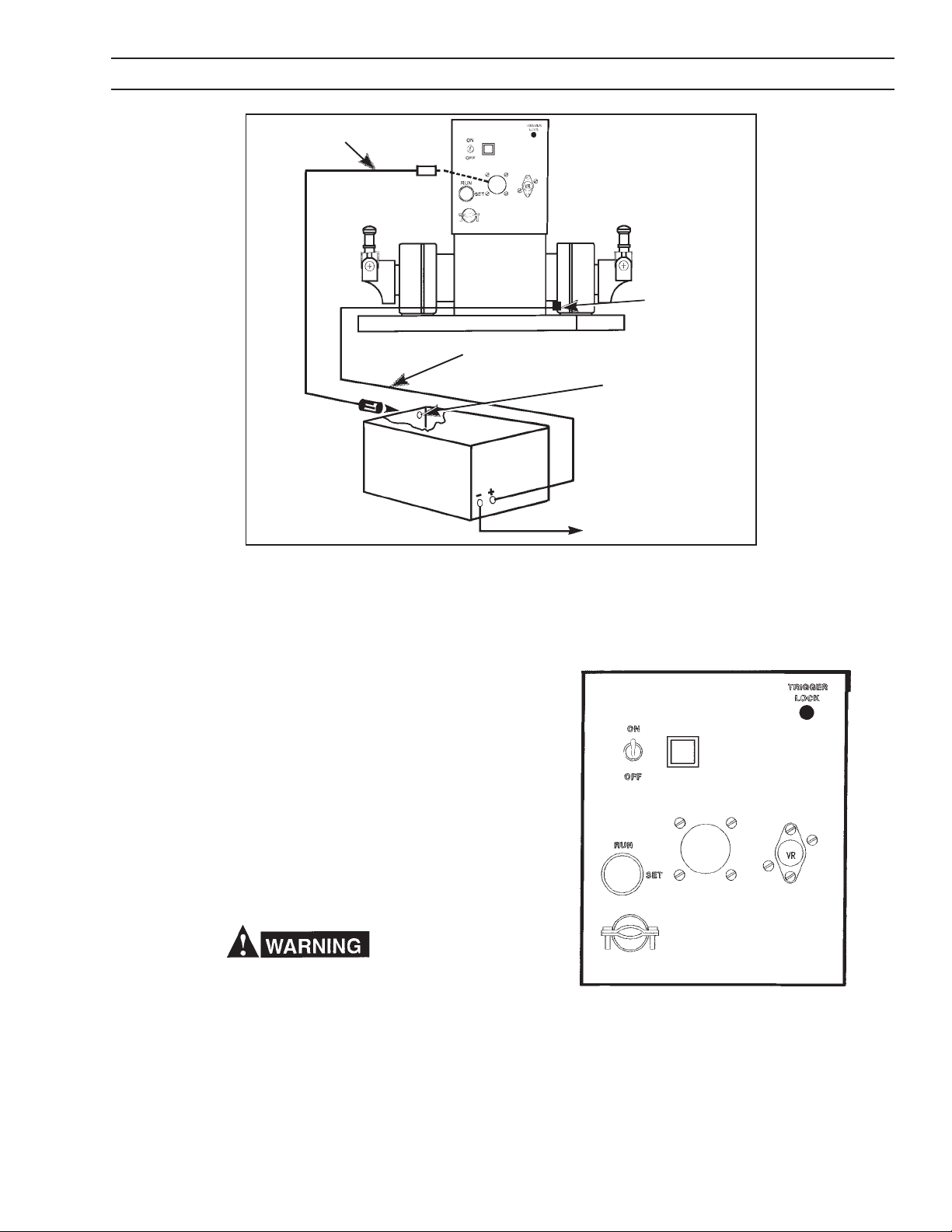
Fig. 4 - Rear Panel Control
A. CONTROL FUNCTIONS
For location of rear panel control features, refer to Fig. 4.
1. Power Switch. This two-position toggle switch turns
power on or off to the wire feeder control.
2. Run Set Key. This "key-operated switch must be in
the SET position to preset, vary and weld-test the
welding parameters programmed into the control (e.g.:
13
Page 14

SECTION 2 INSTALLATION
Sched. I, Sched. II for each torch, Spot). After the
desired results are achieved, the program(s) can be
locked-in by turning the key to the RUN position. The
only parameter which can be altered by the operator
in the RUN position is the cold wire INCH speed.
3. Reset Circuit Breaker. A seven (7) ampere circuit
breaker provides protection to the 115-volt control
circuit and the wire feed motor. If an overload occurs,
the breaker will trip and suspend all operation. To
restore service, depress the breaker button to reset
the circuit.
4. Digital Readout Windows. Two individual three-digit
windows are provided to display preset or actual
welding parameters as follows:
a. IPM Digital Readout. This window is primarily
used to display wire feed speed in IPM from 20 to
999 inch per minute in one inch increments. However, with the appropriate function selector actuated, this window can also display the following:
shielding gas PREFLOW from .1 to 99.9 sec-
onds in one tenth of a second increments.
SPOT welding time for each Torch, from 1 to 999
cycles in 1 cycle increments.
cold wire INCH speed in IPM from 50 to 999
inches per minute in one inch increments.
Schedule select-Left Torch
Crater time - Left Torch
NOTE: With the power turned on, but not welding, the
IPM window will continuously read Preset wire
speed. When the arc is struck, the IPM window
will then continuously read Actual welding wire
speed.
b. Volts Digital Readout. This window is primarily
used to display arc voltage in VOLTS from 12 to 50
vdc in one tenth volt increments. However, with the
appropriate toggle selector actuated, this window
can also display the following:
shielding gas POSTFLOW from .1 to 99.9 sec-
onds in one tenth of a second increments.
accumulative welding ARC HOUR usage record
in one tenth of an hour increments.
manual BURNBACK time. Manually adjustable
burnback time period which when preset will
override the automatic adaptive anti-stick fea-
ture. This time period will be set In one-cycle (60
cycle = 1 sec.) Increments. When set to zero,
the Automatic Anti-stick feature will be opera-
tional.
Schedule select - Right Torch
Crater time - Right Torch
NOTE: With the power turned on, but not welding, the
VOLTS window will continuously read Preset
voltage. When the arc is struck, the VOLTS
window will then continuously read Actual welding voltage.
5. LED Light. This LED lights to indicate that the torch on
the left side is in use.
NOTE: All of the following controls are spring-loaded,
center-return toggle switches which must be
operated to actuate their indicated function(s).
Item No. 6 describes the adjustment setting
toggle used to preset the program- function
selectors. Except as noted above and following,
regulation for selected function(s) can only be
made if Item No. 2 is in the SET position.
5
4A
6A
7
9
Fig. 4A - Front Panel Controls
4B
6B
8
6. Inc.-Dec. Toggle Switches. Two control toggles are
provided to preset the individual welding parameters
required for the selected welding mode as follows:
a. IPM Increase/Decrease Control. This toggle
switch is primarily used to set and/or vary the wire
feed speed (IPM), along with its other functions;
Preflow, Spot for both torches, Inch, Crater time
and Left Side schedule. With appropriate function
selector actuated, each parameter setting will be
displayed in the digital window directly above this
toggle.
b. VOLTS Increase/Decrease Control. This toggle
switch is primarily used to set and/or vary the arc
Volts, along with all its other functions: Postflow,
Burnback, Right Side schedule and Crater time.
With the appropriate function selector actuated,
each parameter setting will be displayed in the
digital window directly above this toggle.
7. Inch-Gas Purge/Abort Reset Selector. This two
position (momentary on contact) switch allows the
following operation.
a. Inch Function. The INCH selection permits cold-
wire inching without energizing the welding circuit
through the torch switch. The preset cold wiring
inching speed (set in Item 9) can also be indepen-
14
Page 15

SECTION 2 INSTALLATION
dently changed by operating its associated Inc./
Dec. toggle switch, and this setting (which is independent of hot wire feed) will appear in the IPM
window.
b. The Gas PURGE (Abort Reset) position provides
the following when actuated:
(1) During initial programming, it permits preset-
ting of gas PREFLOW and POSTFLOW time
requirements which are simultaneously displayed in the IPM and VOLTS windows respectively.
(2) Prior to actual torch triggering, it permits you
to actuate the gas solenoid and PURGE the
shielding gas line of the torch. At the same time,
it also lets you adjust the gas regulator without
energizing the welding circuit.
(3) After starting the welding sequence, if an
abort-shutdown condition occurs (indicated
by a flashing digital display). The RESET position can be actuated and the control automatically resets for a new start.
8. Spot/Burnback. This two- position (momentary contacts) switch allows the following operations:
Spot Weld/Manual Burnback times. Actuating this position allows you to preset either or
both of these features for either or both torches.
The SPOT time mode can be programmed into
either schedule (I or II) for each torch and the
torch selected for operation is chosen by simply
squeezing and releasing the torch switch lever
for the particular torch desired. These preset
timed-arc periods (up to 999 cycles, in one
cycle increments) are programmed in the IPM
window using its Inc/Dec toggle switch. When
the Spotwelding feature has been preset into
one of the schedules for a particular torch,
all continuous" welding applications for
that torch are temporarily disabled. To re-
sume normal program operation in Schedules I
and II for either or both torches, you must deactivate the Spotweld mode by keying its timing
parameter back to zero.
When a spotweld time is programmed for a
torch, the "click-click" torch switch feature for
changing schedules cannot be used as it was for
continuous-type welding operations. To change
schedules for spotwelding, you must manually
reposition the Schedule toggle switch selector to
the desired schedule for that torchthe torch
switch is only used to start the arc, and the spot
time cuts it off (unless the torch switch is prematurely released).
At the same time, you can also preset a
manual BURNBACK time mode into any sched-
ule for each torchand the torch selected for
programming is chosen by simply squeezing
and releasing the torch switch lever for the
particular torch desired. The manual Burnback
time(s) is adjustable in one cycle increments
(60 cycles/sec.) and is programmed in the
VOLTS window using its Inc/Dec toggle switch.
When preset, the Burnback time will override
the automatic adaptive anti-stick feature in either schedule for that particular torch. If automatic anti-stick operation is desired, the
Burnback time must be keyed back to zero.
Schedule Select. When the switch is in the
schedule select position, any schedule from 1
through 8 can be selected for the torch in use.
Schedules 1 - 4 are provided for pulse welding
and schedules 5 - 8 for short arc welding.
9. "Crater" Times/Conditions. This toggle switch allows the operator to preset a special welding wire
feed speed (IPM), arc length (VOLTS) and time
(TIMES) to control the shape and size of the weld
crater .
Each weld schedule can be preset with a unique
crater fill IPM, VOLTAGE and crater time.
B. GAS/WIRE ADJUSTMENTS
The following Digipulse control functions must be set to
feed wire through the torch conduit and to adjust the
shielding gas flow rate.
1. Place Power switch (rear panel) to on position to
energize the control.
2. Place key-operated Lock-In Set switch (rear panel) in
Set position.
3. With torch connections made as shown in Fig. 2, and
wire engaged in accessory support (Sect. IV-E), feed
wire through torch conduit and into torch as follows:
a. Actuate and immediately release the torch switch
lever for the Left Torch/Motor. This action (thru the
controls switching relay circuitry) sets-up the control to receive the parameter programming for the
Left Torch.
b. Remove nozzle and contact tip from torch.
c. Hold Inch-Purge toggle in INCH position (Sect. V-
A-8) until cold wire protrudes from the torch front
end.
d. Slide the contact tip over the end of the wire and
secure it to the torch. Replace the torch nozzle.
e. Reoperate Inch-Purge toggle in INCH position and
check for wire feed slippage on the accessory
support assembly. Tighten (or loosen) the pres-
sure adjusting knob until the wire feeds smoothly.
f. Now, actuate and immediately release the torch
switch lever for the Right Torch/Motor. This action
(thru the controls switching relay circuitry) sets-up
the control to receive the parameter programming
for the Right Torch, and you can repeat steps b-e.
15
Page 16

SECTION 3 OPERATING INSTRUCTIONS
4. With shielding gas cylinder and torch gas hose connection assembled as shown in Fig. 2, set gas flow
rate as follows:
a. Hold Inch-Purge toggle in PURGE position and
open the gas regulator-flowmeter control valve and
set the shielding gas flow rate.
b. Continue to hold the Purge position for approx. 15
seconds to insure adequate purging of each gas
hose and torch.
5. Place controls Power switch to off position.
VI GENERAL
This dual pulse Mig welding system has been
designed and manufactured to specifications provided
by Bombardier, Inc.. The software is modified to
provide eight separate schedules for each torch. The
first four schedules (1-4) on each torch are dedicated
to pulse welding of stainless steel in the synergic
mode. The second four schedules (5-8) are dedicated
to short or spray arc welding and have no synergic
relationships. This means that IPM and VOLTS are
entered separately depending if a short arc or spray
arc weld condition is required. The following will detail
the set-up and operation of this unique welding
system.
Start Up
Assembly of the power source, feeder and
interconnect cable is the same as specified in the
general operating instruction manuals provided with
the SVI-450i Power Source and Digipulse Dual wire
feeder. After power up of the SVI-450i (460 Vac) and
the feeder, the windows on the feeder will display
IPM=51 and VOLTS=45 for a brief period. This
indicates that the stainless steel program (same as a
standard Digipulse) is running and the synergic curve
is for .045-inch (1.2 mm) diameter wire. These
parameters CANNOT be changed. The windows will
then display the last welding parameters set by the
operator. Place the Remote/Panel switch on the
SVI-450i power source in the Remote position and
follow the instructions below.
Set the shield gas preflow parameters by holding
down the Purge key and using the Inc/Dec key
under the IPM window to set a preflow time in 1/10
seconds. Repeat the above for postflow using the key
below the VOLTS window.
The cold inching feature is a two speed design. When
placing the Inch key in the up position, the feed
motor will operate at 50 ipm for a period of 2-1/2
seconds. This is for bumping the wire to adjust the
wire stick-out from the contact tip. After 2-1/2
seconds the wire feed speed will transfer to the cold
inching speed shown in the IPM window. The wire
feed speed can be further adjusted using the Inc/Dec
key under the IPM window. This function is designed
for wire threading.
The Trigger Selection option allows dual schedule
operation. This means that two welding schedules are
available to the operator on each torch. This option is
disabled when Rocker Switch #4 on Dip Switch #2 is
in the closed position. Dip switch #2 is located on
the MPU board inside the feeder control box. Place
this switch in the open position for Trigger selection
(dual schedule operation). Welding will always begin
using the current weld schedule selected. Double
clicking the torch trigger switch changes the welding
parameters to the next highest schedule number. See
diagram below.
Example:
If pulse arc welding is being used in schedule #4,
double click the torch trigger to switch to the short/
spray arc parameters resident in schedule #5.
Double click the torch trigger a second time causes
the weld parameters to switch back to the pulse weld
parameters in schedule #4. Releasing the torch
trigger stops welding.
Selecting System Presets
System parameters are those that affect BOTH
torches and ALL schedules. These parameters are
always active and should be set first. They are:
Gas preflow preset
Gas postflow preset
Cold inch preset
Trigger selection (dual schedule operation)
Half speed run-in
16
Page 17

SECTION 3 OPERATING INSTRUCTIONS
The Trigger Selection function (dual schedule
operation) is automatically disabled when a spot weld
time is preset or its crater conditions are set for the
schedules in use on that torch. See Torch Parameter
Presets below.
Half speed run-in is always on when using the pulse
arc schedules (1 to 4). Half speed run-in will also be
on in the short/spray arc schedules (5 to 8) when the
arc voltage is 26 volts or higher. Below 26 volts will
result in full speed run-in of the welding wire. This
option is enabled when Rocker Switch #1 on Dip
Switch #2 is in the open position. Dip switch #2 is
located on the MPU board inside the feeder control
box . Place this switch in the closed position for full
speed run-in for all welding schedules 1 to 8. This
function is triggered off the high open circuit voltage
(OCV) of the SVI-450i power source. Half speed runin cannot be enabled using power sources having a
low OCV.
Torch Parameter Presets
Each torch can have the following parameters or
variables preset:
Attach the desired gas mixture to the appropriate torch
for the type of welding to be completed.
Some shielding gases will not pulse arc and short arc
equally well. Therefore, the optimization of both pulse
arc and short/spray arc parameters will be dependent
on the shielding gas and its ability to support both
processes.
If spot welding is desired, depress the torch trigger
switch to be preset. This action displays the current
welding parameters for that torch. Hold the
Burnback/Spot key in the up position and set a
spot time in seconds in the IPM window. Repeat this
procedure for the other torch if desired. Entering a
spot weld time automatically disables the Trigger
Selection mode and dual schedule operation is not
possible.
Weld Schedule Parameter Presets
Pulse Arc Welding
Schedule number preset
Wire burnback preset
Spot weld time
Crater time
Crater conditions
The software will automatically switch to the torch
being used when the torch trigger is depressed. Each
torch may have two welding schedules assigned at a
time when using the Trigger Selection mode
(described above). The right side torch (viewed from
the front of the feeder) is the default torch setting.
This means that when the feeder is first powered up
this torch and its parameters will be displayed. If a red
light between the IPM and VOLTS display windows is
illuminated, the left side torch parameters are being
displayed.
Choose the schedule number (1- 8) for each torch by
depressing the Schedule Selection key and setting
the desired schedule number in IPM window for the
left torch and the VOLTS window for the right torch.
Preset the desired burnback by depressing the torch
trigger switch to be preset. This action displays the
current welding parameters for that torch. Hold
Burnback/Spot key in the up position and set a
burnback number in VOLTS window. Repeat this
procedure for the other torch.
Schedules 1 through 4 are dedicated pulse arc
welding schedules for stainless steel using .045" (1.2
mm) diameter wire. The synergic relationship is the
same on each torch and for each schedule. When
entering a schedule number 1 to 4, the feeder control
and power source is automatically set for pulse
welding with .045" stainless steel wire.
Note: The SVI-450i power source slope switch should
be set to the STEEP slope position. The
INDUCTANCE & VOLTAGE knob on the SVI450i is deactivated.
The IPM window will display the wire feed speed in
inches per minute and the VOLTS window will show a
number between 0 and 200 with 100 being the default
value. These numbers relate to the synergic
relationship programmed into the software and
correspond to a pulse frequency. The number 100 is
the nominal pulse frequency required for the wire feed
speed selected in the IPM window. This number will
also affect the arc length. If the welding arc length is
too long the number can be decreased which shortens
the arc length. If the welding arc is too short, increase
the number in the VOLTS window. Each count in the
window changes the pulse frequency by one pulse per
second.
17
Page 18

SECTION 3 OPERATING INSTRUCTIONS
Short/Spray Arc Welding
When setting a schedule number 5 to 8, the feeder
control and power source is automatically set for
short/spray welding. The operator has full control over
the slope and inductance of the power source. The
IPM window will display the preset wire feed speed in
inches per minute. The VOLTS window will display
arc voltage and can be adjusted to any arc voltage
needed for a good welding condition by using the Inc/
Dec key under the VOLTS window. The feeder
control will automatically adjust the power source to
maintain the arc voltage set in the VOLTS window.
There is no synergic relationship present in the short/
spray arc schedules.
Crater Fill
The Crater Fill feature allows the operator to preset a
special welding wire feed speed (IPM), arc length
(VOLTS) and time (TIMES) to control the shape and size
of the weld crater upon termination of the welding process.
Each weld schedule can be preset with a unique crater
fill IPM, VOLTAGE and crater time. The feeder thus offers 16 sets of crater conditions.
Note
When a crater TIME is programmed, the double click
method of changing torch schedules by using the welding torch trigger is automatically disabled for that torch.
5. The preset crater time can be terminated also by
reoperating the torch switch during the crater condition.
6. For a legitimate crater condition, both crater speed
and crater time needs to be set.
Arc Start (Servo) Settings - For short or spray arc
welding only, not applicable to pulse welding.
Each schedule on each torch can have its own starting
characteristic for any given weld parameter. The arc
start level must be set during welding. Choose
desired schedule number and set a good welding
condition. If the arc starting is less than desirable it
can be adjusted as follows:
Depress the Purge and Schedule Select key
simultaneously while making a weld (two man
operation). The VOLTS window will display a number
between 0 and 200 (95 is the typical setting). Using
the Inc/Dec key below the VOLTS window, reduce
the number shown to give a hotter arc start or
increase the number for a colder arc start. Your
setting will be saved to that schedule and will be
recalled when you select that schedule again.
Changes in wire feed speed and/or voltage might
necessitate readjusting the voltage servo to optimize
starting characteristics. Repeat this procedure for
other welding schedules being used.
Note: The set number 80 - 95 will only effect the
starts, it will not change the preset arc voltage.
Programming a Crater Condition
1. Momentarily depress the trigger of the torch to be
programmed. Be sure the desired schedule number is assigned to that torch. Schedules 1 - 4 are
Pulse arc welding schedules and schedules 5 - 8
are Short Circuiting/Spray arc welding schedules.
2. Hold the Crater toggle switch in the TIMES position.
The window corresponding to the torch being used
will illuminate. Enter the desired crater time (in seconds) using the INC/DEC switch under the illuminated window. A zero (0) will disable the crater fill
feature.
3. Hold the Crater toggle switch in the CONDITIONS
position and enter the crater IPM and VOLTS settings desired using the INC/DEC toggle switches
beneath their respective window.
4. During welding the crater fill schedule will be enabled when the operator releases the torch trigger.
The crater timer will start and the arc will extinguish
automatically when the preset crater time has timed
out.
Motor Servo Setting
You can adjust the feed motor response by presetting
the motor speed servo. Release the pressure roll and
pull the torch switch while depressing the Purge and
Schedule Select key simultaneously. Change the
number (110 is standard) in the IPM window using the
Inc/Dec key to a lower value if a faster motor
acceleration is needed or a higher number for a
slower motor acceleration.
The motor response adjustment will be in effect
for ALL schedules and BOTH torches. The servo
number set in the IPM window can be set exactly
for the schedule being used and wire feed speed
preset but switching to a different schedule
having a different wire feed speed setting will
cause the servo number in the IPM window to vary
slightly. This is normal and should have little
affect on welding performance.
18
Page 19

SECTION 4 MAINTENANCE
Vll. TROUBLESHOOTING
Listed below are a number of trouble symptoms
each followed by the checks or action suggested to
determine the cause. Listing of checks and/or actions is in most probable order but is not necessarily 100% exhaustive. Always follow this general
rule: Do not replace a printed circuit (PC) board until
you have made all the preceding checks. Always put
the Power switch in off position before removing or
installing a PC board. Take great care not to grasp or
pull on components when removing a PC board.
Always place p. c. boards on a static-free surface.
If a printed circuit (PC) board is determined to be the
problem check with your ESAB supplier for a tradein on a new PC board. Supply the distributor with the
part number of the PC board as well as the serial
number of the wire feeder. Do not attempt to repair
the PC board or any other component yourself.
Warranty on a PC board or control will be null and
void if repaired by customer or an unauthorized
repair shop.
A. General
1. Check interconnection between digipulse control and
power source. Make sure that the contactor and
voltage control switches are placed in the Remote
position.
2. Energize the power source and the control.
3. Immediately after the control is turned on, a number
(e.g.: 3) will appear in the IPM readout window and will
only be displayed for 1-second. This number identifies
the current program (E-Prom) used in your control.
When a Program is changed, the new E-Prom will
automatically identify the new program number being
used. If a revision is made to an existing program a
number .1, .2, .3, etc. indicating the numerical revision
will also appear in the VOLTS readout window simultaneously.
4. After the one (1) second delay; the preset Weld
parameters for the Right-Side Torch will be displayed in the IPM and VOLTS windows.
5. If the control is not functioning properly (or as described above); for example, the numbers that appear
in one or both of the display windows are meaningless
(all zeroes, eights, decimals, etc.), or are completely
incorrect in relation to your settings,the memory
must be cleared. This condition might occur after a
bad lightning storm, extremely bad power line surge,
etc. To clear the memory, do the following:
a. Place the Run-Set key switch in its SET position.
b. Turn off the units 115-volt Power switch.
c. Using one hand, hold both of the Inc/Dec toggle
switches in their INC position while reapplying 115volt power with the other hand.
d. Almost immediately after the Power has been
turned On, release the Inc/Dec toggle switches to
the neutral (spring-return center) position and each
of the windows should display one zero, indicating
a successful reset or clearing has taken place.
6. You can now enter the desired information as described in this booklet.
B. No preset displays appear in windows.
1. Make sure the LED Display board harness/plug is
plugged into the P5 receptacle on the MPU board.
2. Check that 110 vac is available across terminals T118 and T1-19, if present;
3. Check for plus (+) 5 volts between terminals T1-8 and
T1-9; if voltage is present, replace the MPU board. If
voltage is not present, check the voltage regulator
(VR). The voltage regulator is located on the rear
panel of the control box.
4. Check the input and output voltage of the regulator
VR.
a. The input should be approx. 11 volts between VR-
1 and T1-9. If voltage is not present, replace I/O
board.
b. The output should be + 5 volts between terminals
T1-8 and T1-9. If voltage is not present, replace VR,
voltage regulator.
C. Preset display is provided, but cannot be varied.
1. Check normal setup procedures described in Section
VI, then;
2. Make sure the Inc/Dec key harness plug is properly
connected to receptacle P6 on the MPU board and the
lock-in key switch is placed in its SET position.
3. If neither of the above resolve the problem, replace the
MPU board.
D. Motor does not run.
1. Check to make sure all required accessories are
correctly assembled as described in Section IV.
2. Make sure that power source is connected, plug P2 is
securely connected to receptacle P2 on the Digipulses
I/0 Board, and then release the clapper arm (pressure
roll) on the Accessory Support Assembly.
a.Operate the Digipulse INCH switch. If motor does
not run; replace the J governor board, and if it still
does not run, replace I/O and MPU boards respectively.
b.If the motor inches, but does not run when the torch
switch is operated (energized), check the torch
switch circuit componentsswitch, plug, receptacle, etc. If motor still does not run, check if power
source is providing open-circuit voltage to the
19
Page 20
SECTION 4 MAINTENANCE
Digipulse if o.c.v. is not being supplied, motor will
not run. Check the power source for trouble.
c.Also check that +/- 12 volts d.c. are provided from
the power source on T1-7 and T1-5 respectively.
d.If power source is O.K., replace the I/0 and MPU
boards respectively.
E. Motor runs, but not at right speed.
1. Check tachometer assembly mounted on the end of
EH-10A wire feed motor.
2. Make sure the tach disc is securely fastened to the
motorshaft and that the strobe markings are not
scratched. Check that the disc is properly centered
in the optical switch on the p.c. board.
3. If all items in step 2 are in order, and motor speed
is still incorrect, replace MPU board.
F. Arc VOLTS display reads zero after TS Is operated.
1. Check that the 5-pin plug is securely connected to the
P3 receptacle on the MPU board
2. If no reading is displayed, check for arc voltage
feedback between terminals TP1 and TP2 test points
on the I/0 board (see Fig. 4B). This voltage signal
should correspond to that shown on the power source
voltmeter.
3. If voltage still reads zero, trace the voltage pickup
wiring from the power source to digipulse.
4. Remove the J-Gov. p.c. board to gain access to the P3
plug (harness) on the MPU p.c. board. Disconnect the
P3 plug from its MPU board socket and, using a meter
check for +/-12 volt power supply output between plug
pins P3-1 and P3-2 (for +12 v.) and between plug pins
P3-4 and P3-2 (for -12 v.) respectively. If voltage is
present, replace the MPU board.
If this condition occurs, the respective servos need to
be checked and, if necessary, readjusted.
1. This symptom can of occur as a result of either or all
of the following; the Speed and Voltage servo) adjustments are incorrect and the conditions set may not
be maintainable. To check and, if necessary, readjust
the servos proceed as follows:
NOTE: Prior to checking the servos, make sure the
Digipulse is connected to SVI-450i power source
in order to obtain the necessary o.c.v. (open
circuit voltage); otherwise, the motor will not run.
2. The Speed and Voltage servos in this control are
simultaneously checked and displayed by depressing
and holding the front-panel Schedule Select switch in
its "down" position during an actual weld with the
wirefeed motor running. The speed servo number is
displayed in left (IPM) window and should be about
110, and the right (VOLTS) window will display the
voltage servo number. This number will be between
90 and 100* for the actual welding condition.
* Voltage servo setting below 95 will normally provide hot arc
starts; whereas, setting over 100 will not.
3. If a Speed abort had occurred (IPM window flashing),
check and/or adjust the speed (servo) as follows:
Open the pressure roll clapper (so as not to feed wire),
toggle-down the Schedule Select switch position, and
either close the torch switch lever or toggle-up the
INCH position of the Inch-Purge switch. Check the
number in the IPM window it may appear unsteady
but readable and should be about 110.
Fig. 4B - Input/Output (110) P.C. Board
G. Control Shut Down either preset VOLTS or IPM
displays will flash. The control will flash the parameter,
VOLTS or IPM, that cannot be maintained.
If it is higher or lower, use the Inc/Dec toggle (below
TP2
the IPM window) to adjust the number to 110 - while
TP1
holding the A.H./INCH Preset and Purge/Reset toggle
as mentioned above and while the wire feed motor
is running.
If the speed servo cannot be adjusted at all, the
problem may be in the J-Governor, and/or I/O, and/or
MPU p.c. boards which needs to be as required.
4. If a Voltage abort had occurred (VOLTS window
flashing), check and/or adjust the voltage (servo) as
follows:
This is a two man operation. Set a welding condition
which closely corresponds to your welding application
and the proper speed (ipm) for a given wire size and
then close the torch switch and strike a welding arc.
While welding, toggle-down the Schedule Select switch
20
Page 21

SECTION 4 MAINTENANCE
position and read the number displayed in the VOLTS
window, it may appear unsteady but readable and
should be 95.
If the number is not in the 90-100 range, use the Inc/
Dec toggle (below the VOLTS window) to adjust the
number to 95 while holding the toggle positions
mentioned above and while welding.
5. If the voltage servo cannot be adjusted, check for
proper operation of the power source as follows:
a. Set the Digipulse voltage display to zero (this
setting will override the servo).
b. Place the Panel/Remote switch on the power source
in PANEL position.
c. Make a weld by controlling the arc voltage directly
from the power source potentiometer.
d. If a weld can be made with good control over power
source voltage; a problem exists either in the interconnecting voltage control cable, or in the Digipulse
control.
e. Check the control wires in the interconnecting
voltage control cable for continuity between the
appropriate terminals in the power source and
digipulse using the schematic diagrams.
f. If continuity is correct, replace the I/O board and/or
the MPU board.
H. Control Shut-Down Due to Ground Fault Detec-
tion both IPM and VOLTS displays will flash.
The purpose of this circuit is to make sure that welding
current is not present in the wire feeder frame/base,
control box, or the equipment safety ground. If this
should occur, the ground fault detector will temporarily
energize and immediately terminate the weld. This abort
is indicated by both visual displays flashing simultaneously. Before attempting to make a new weld, make
sure that the Work Ground cable and its connections are
properly and securely made to the workpiece.
VIII. MAINTENANCE
If this equipment does not operate properly, stop
work immediately and investigate the cause of the
malfunction. Maintenance work must be performed
by an experienced person, and electrical work by a
trained electrician. Do not permit untrained persons
to inspect, clean, or repair this equipment. Use only
recommended replacement parts.
A. GENERAL MAINTENANCE
Little maintenance is required to keep the wire feeder in
top operating condition. It is important, however, that
moving parts such as feed and pressure rolls, wire feed
motor, etc., be kept clean and free of dust or dirt.
Cleaning is best accomplished by regularly blowing off
these parts with dry compressed air. This should be done
once for every eight hours of operating time, more often
if necessary.
B. LUBRICATION OF DIGITAL MOTOR-GEAR UNIT
The EH-10A motor-gear digital unit is lubricated with a
heavy duty grease when assembled at the factory and
should not require further lubrication unless disassembled.
If disassembled relubricate with Texaco Multifak grease.
C. CHECK OR REPLACEMENT OF MOTOR BRUSHES
Motor brushes should be checked periodically. If a brush
is broken, or worn down to less than 3/8-in. length, it must
be replaced. Brushes can be inspected by unscrewing
the brush-holder plug and withdrawing the brush assembly. Never remove a brush without matchmarking it and
its holder, so that it can be replaced in the same holder
in its original position.
D. REMOVAL OF EH-10A DIGITAL WELDING HEAD
1. Unplug the control cables from the rear panel of the
wirefeeder control.
2. Remove the accessory support assembly from the
motor-gear unit by loosening the cap screw at the
bottom of the assembly.
3. Disconnect the motor and tachometer cables from
terminal board (T1) inside the control assembly as
shown on the wiring diagram.
4. Remove the four screws which secure the digital
motor-gear unit to the base and remove the digital
unit.
E. ADDITIONAL DIGIMIG PROGRAM FEATURES
The Digipulses MPU board contains an integral 4-rocker
dip switch (SW1) that is factory-set to the following
positions: Rocker #1 is CLOSED, and Rockers #2, 3, 4
are OPEN. The microprocessor technology utilized by
the Digipulse control is extremely versatile and can be
modified for specific purpose by ESABs engineering
services group. To add specific features or programs to
your unit, consult your ESAB representative. If additional
optional features are provided, the SW1 rocker positions
may need to be repositioned and this information will
be conveyed in the appropriate instruction booklets
provided with the option kits.
21
Page 22

SECTION 5 REPLACEMENT PARTS
1. All replacement parts are keyed on the illustrations which follow. Order replacement parts by part number and
part name, shown on illustrations. DO NOT ORDER BY PART NUMBER ALONE.
2. Always state the series or serial number of the machine on which the parts are to be used. The serial number is
stamped on the unit nameplate.
COVER - 30170YL
WARNING DECAL - 2091514*
CONTROL ASSY.
33387 (see Fig. 7)
(SW1, 3, 5, 7) SWITCH - 950087 n
(2) ACCESSARY SUPPORT ASSY.
2 ROLL DRIVE (See Fig. 8) - 49V51
LEFT TORCH (J4) RECEPTACLE 182W64
C16 CAPACITOR
672348
FRONT VIEW
WARNING DECAL - 995204*
RIGHT TORCH (J3) RECEPTACLE
- 182W64
(C10, 11) CAPACITOR
- 672348
(2) EH-10A DIGITAL MOTOR-GEAR
UNIT ASSY. 679777 (See Fig. 6)
FRONT CONTROL SUPPORT - 35742
(CB) CIRCUIT BREAKER - 950874 n
(MSL) POWER ON-OFF SW
uRUN-SET SW - 950956
STRAIN RELIEF - 96W76
(2) GAS SOLENOID VALVE - 2062305 n
(2) GAS INLET CONNECTION - 74S76
(2) GAS BULKHEAD ADAPTOR - 58V58
KNOCKOUT OPTIONAL
WATER CONNECTIONS (See Fig. 10)
REAR CONTROL SUPPORT
36278
Not Illustrated Accy. Support
INSULATOR RING
60N90
Key - 28N33
THUMBSCREW
61351087
FLATWASHER - 64309431
BELLEVILLE WASHER - 950783
634517 n
(J1) RECEPTACLE - 950762 (19-pin)
C20 CAPACITOR - .1uf, 500 V
(VR) VOLTAGE REGULATOR includes:
VOLTAGE REGULATOR - 950159
TRANSISTOR SOCKET - 950158
(C4) CAPACITOR - 995544
BASE w/SUPPOFT - 36279
REAR VIEW
u Replacement key for Run-
Set SW - 32778
POWER CABLE ADAPTOR BLOCK - 674156
1/2-IN.-13 STL. NUT
1/2-IN. LOCKWASHER
(2) 1/2-IN. FLATWASHER
Fig. 5 - DIGIPULSE Dual Wire Feeder, P/N 33299
22
(2) SPINDLE ASSY.
948259 (See Fig. 9)
* Replace decal if it becomes
excessively worn or lost when
replacing panel(s)
n Recommended Spare Parts
n Recommended Spare Parts
Page 23

TACH. P.C.B.D.
675429
(2) Screw-61324746
Gear Case Lubricated with
Texac Multifak Grease
11.6
2.875
.020
REF
2.370
.93
TACH HOUSING - 18786
(2) 8-32 X 3/8" Screw
4.010 SQ.
2.25
2.000
23
TACH DISK
950313
MOTOR END
HOUSING
TACH COVER - 18787
(2) Screws 61324974
(Ref.) 54" LG
3.25
VENT PLUG
10
33 LOCATING COLLAR
50
DP
MIN.
.6251
(REF.)
w/COVER REMOVED
Fig. 6 - EH-10A Digital Motor-Gear Unit Assembly (40:1) P/N 679777
END VIEW
MTR.
LEAD
1.375
5.16 18 UNC 2B
1.375
.25
63 MIN. DEPTH
FOR MOTOR REPLACEMENT
PARTS (See Fig. 6A)
.25
2.86
Page 24

24
WARNING DECAL - 995164*
DISPLAY P/C BOARD
ASSY. - 675236
J GOV. P/C BOARD
ASSY. - 994236 (See Note)
MTG. Bracket - 995297
(P1) Receptacle - 636608
(I/O) P/C BOARD ASSY. - 674994
(I/O P4 to MPU P2) CABLE ASSY. - 677938
(MPU) P/C BD. ASSY. - 18155
(RLY) RELAY - 951089
C21, C22 - CAPACITOR - .1uf, 500V
BR-RECTIFIER - 2 Amp., 400v - 63515
(R1) RESISTOR 17240001
(25W, 3 ohm)
(MOV) METAL OXIDE
VARISTOR - 995104
(FN1) FILTER
NETWORK - 679874,
Includes
C1, C2 CAPACITOR 950702
C3 CAPACITOR 993716
NOTE:
The heat sinks of the J gov. board
are electrically hot. Do Not touch
or ground while unit is energized.
(T1) 20 PT. Terminal
Strip - 950182
(GRF) SENSOR - 950448
(Mtd. on Cabinet Base)
Fig. 7 - DIGIPULSE Dual Control Assembly P/N 33387
(CTR1,CTR2) CONTROL TRANSFORMERS
CTR1 - 950088
CTR2 - 994303
BRACKET - 35477
* Replace decal if it becomes
excessively worn or lost.
Recommended Spare Parts
Page 25

CLAPPER - 60N98
SHAFT - 60N65
KNOB - 60N68
ROLL PIN 1/4" X 1-3/4" LG
INLET
INLET WIRE GUIDE
29N13
INLET GUIDE INSERT
05N58
WIPER HOLDER*
598764
SET SCREW # 6-32 X 1/4" LG
61330849
(2) LOCKING HANDLE ASSEM - 49V44
INCLUDES:
BOLT 1/4" x 1-5/8"
LG
SPACER - 60N79
PRESSURE ROLL
SUPPLIED
HEAVY SPRING - 182W54 (FOR LARGE DIA. HARD WIRE)
28V52
LIGHT SPRING 182W55 (FOR
SOFT & SMALL DIA. HARD WIRE)
RETAINER 58N24
FORK - 49V43
ROLL PIN 3/16" X 1-3/4" LG
SCREW 5/16" -18 X 2" LG
NUT 5/16"-18
*Outlet guide And Wiper Holder Not Included in Assembly Part No. 49V51.
Fig. 8 - Accessory Support Assembly, P/N 49V51
WIRE OUTLET GUIDE INSERT*
CONDUIT
OUTLET
WIRE OUTLET GUIDE*
(See Table 1)
CLAMP - 61N02
WIRE REEL - 995570
Includes:
REEL - 995568
COVER - 995569
(4) WING NUT, 1/2" - 13
63398183
(Ref. Hair Pin Clip)
REEL
(4) .359" DIA. HOLE ON 3" DIA. D.C.
SPINDLE - 948258
"D" TYPE
WASHER - 948254
SPRING - 948253
SUPPORT -
(2) BRAKE PAD - 948255
948257
SPINDLE
SCREW 5/16" -18 x 2"
HAIR PIN
CLIP - 634347
WASHER 948256
WATER
CONNECTION
58V75
(OUTLET)
5/8 -18 Lh
WATER
CONNECTION
58V75
(OUTLET)
5/8 -18 Lh
WITHOUT SOLENOID VALVE
WATER SOLENOID
VALVE - 2062355
1/4 N.P.T.
WITH SOLENOID VALVE
COUPLING - 68121075
ADAPTOR - 11N16
(INLET)
5/8 -18 Lh
1/4 N.P.T.
ADAPTOR - 11N16
(INLET)
5/8 -18 Lh
Fig. 9 - Spindle Assembly, P/N 948259,
Optional Wire Reel, P/N 995570
Fig. 10 - Water Kit with Solenoid Valve, P/N 2075760*
Water Kit without Solenoid Valve, P/N 994466
*Do not use with Coolant Recirculator
25
Page 26

Digipulse Dual Control Revision History
Rev. A
Added label P/N 954232 (Schedule Select) to front panel.
Rev. B
Removed the 6 pin (P/N 634772) and 8 pin (P/N 2062106) box receptacles and added a 19
pin (P/N 950762) box receptacle P/N 950762. (Ref. Schematic Diagram Rev.A and Wiring
Diagram Rev. A).
Rev. C
Modified note 7 of the assembly drawing and added the accessory support leads 1&2 to
T1-20 of the wiring diagram. (Ref. Schematic Diagram Rev.A and Wiring Diagram Rev. B).
Rev. D
Changed from a green/light green cabinet with L-Tec decals to a gray/yellow cabinet with
ESAB decals, changed CTR1 and CTR2 from a welded assembly ,added mounting bracket
P/N 35477, and changed the signal lead assembly from P/N 30685 to P/N 36644. Title
Digmig Dual was changed to Digipulse Dual. (Ref. Schematic Diagram Rev.B and Wiring
Diagram Rev. C).
Rev. E
Added Craterfill as a factory installed option.
Digipulse Dual Wire Feeder Revision History
Rev. A
Re-designed the base and reel support , changed the color from L-Tec green to ESAB
gray/yellow.
26
Page 27

27
Page 28

ESAB Welding & Cutting Products, Florence, SC Welding Equipment
COMMUNICATIONS GUIDE - CUSTOMER SERVICES
A. CUSTOMER SERVICE QUESTIONS: Telephone (843) 664-5540/Fax: (800) 634-7548
Order Entry Product Availability Pricing Hours: 8:30 AM to 5:00 PM EST
Order Changes Saleable Goods Returns Delivery
Shipping Information
B. ENGINEERING SERVICE: Telephone: (843) 664-4416 / Fax : (800) 446-5693
Welding Equipment Troubleshooting Hours: 7:30 AM to 5:00 PM EST
Warranty Returns Authorized Repair Stations
C. TECHNICAL SERVICE: Telephone: (800) ESAB-123/ Fax: (843) 664-4452
Part Numbers Technical Applications Hours: 8:00 AM to 5:00 PM EST
Performance Features Technical Specifications Equipment Recommendations
D. LITERATURE REQUESTS: Telephone: (843) 664-5501 / Fax: (843) 664-5548
E. WELDING EQUIPMENT REPAIRS: Telephone: (843) 664-4469 / Fax: (843) 664-5557
Repair Estimates Repair Status Hours: 7:30 AM to 3:30 PM EST
F. WELDING EQUIPMENT TRAINING:
Telephone: (843)664-4428 / Fax: (843) 664-4476
Training School Information and Registrations Hours: 7:30 AM to 4:00 PM EST
G. WELDING PROCESS ASSISTANCE:
Telephone: (800) ESAB-123 / Fax: (843) 664-4454 Hours: 7:30 AM to 4:00 PM EST
H. TECHNICAL ASST. CONSUMABLES:
Telephone: (800) 933-7070 Hours: 7:30 AM to 5:00 PM EST
Hours: 7:30 AM to 4:00 PM EST
IF YOU DO NOT KNOW WHOM TO CALL
Telephone: (800) ESAB-123/ Fax: (843) 664-4452/Web: http://www.esab.com
Hours: 7:30 AM to 5:00 PM EST
F-15-496-A 5/99 Printed in U.S.A.
 Loading...