

Page 1

INSTRUCTIONS for
F-15-075-A
April, 1995
DIGIPULSE AUTOMATIC
MICROPROCESSOR CONTROL
DIGIPULSE
AUTOMATIC
MICROPROCESSOR
CONTROL
P/N 31990
FOR AUTOMATED MECHANIZED MIG
WELDING
SPECIFICATIONS
Input Power Required ....................... 7 Amp., 115 vac, 1ph, 50/60 Hz
Wire Feed Speed Range .................. 20-999 in/min (.5-25.2 m/min)
Wire Sizes Preprogrammed ............. 023-in. (.7 mm), .030-in. (.76 mm),
.035-in. (.9 mm), .045-in (1.2 mm)
and .063 (1.6 mm)
Wire type (mat.) Preprogrammed .... 1. Carbon Steel, 2. Alternate Steel,
3. 4043 Alum., 4. 5356 Alum.
5 . Stainless Steel, 6. Silicon Bronze,
and 7. thru 10. reserved for
custom applications
Dimensions ....................................... 15.5-in. (394 mm) h,
13.0-in. (330 mm) w,
8-in. (200 mm) d
Weight ............................................... 20 lbs (9.1 kg)
These INSTRUCTIONS are for experienced operators. If you are not fully familiar with the principles of
operation and safe practices for electric welding equipment, we urge you to read our booklet, “Precautions and Safe Practices for Electric Welding and Cutting,” Form 52-529. Do NOT permit untrained
persons to install, operate, or maintain this equipment. Do NOT attempt to install or operate this equipment until you have read and fully understand these instructions. If you do not fully understand these
instructions, contact your supplier for further information. Be sure to read the Safety Precautions on
page 3 and 4 before installing or operating this equipment.
Be sure this information reaches the operator.
You can get extra copies through your supplier.
Page 2

CONTACTS
Specifications ...................................................................................................................................................................... 1
Safety Precautions ........................................................................................................................................................... 3/4
Features/Benefits ................................................................................................................................................................ 5
I. INSTALLATION ............................................................................................................................................................. 5
A. Equipment Supplied ................................................................................................................................................. 5
B. Required Accessories .............................................................................................................................................. 5
C. Optional Accessories ................................................................................................................................................ 6
II. OPERATING INSTRUCTIONS ..................................................................................................................................... 7
A. Power Supply Welding Controls ................................................................................................... Refer to F-15-014
B. Digipulse Front Panel Control Functions ................................................................................................................. 9
C. Inside Panel Controls ............................................................................................................................................. 12
III. SETTING UP PROGRAM PARAMETERS ................................................................................................................. 15
A. General Welding Program Data ............................................................................................................................. 15
B. Preliminary Power Supply Checks ......................................................................................................................... 15
C. Program Control Parameters for Short/Spray Pulse Welding
Process Modes (Includes Hot Start Adjustment Procedures) ................................................................................ 15
D. Programming Your Own Pulse Parameters in optional Teach Mode.
Graphs—19) ........................................................................................................................................................... 17
E. Custom Program Development Procedures (Includes Customer
Development Chart ................................................................................................................................................ 21
IV. WELDING OPERATION
A. Pulse/Spray/Short Arc Wire Speed Recommendations ......................................................................................... 21
B. Welding Sequence for Teach Pulse or Spray or Short Arc Mode .......................................................................... 22
V. TROUBLESHOOTING ................................................................................................................................................ 23
VI. REPLACEMENT PARTS DATA .................................................................................................................................. 27
Figure 1 - Digipulse Interconnection Diagram .............................................................................................................. 8
Figure 1A, OM-48 J-Governor Carriage Hookup .......................................................................................................... 9
Figure 2 - Front Panel Controls ..................................................................................................................................... 9
Figure 3 - Inside Panel Controls ................................................................................................................................. 10
Figure 4 - Typical Time Parameter Set-up ................................................................................................................. 16
Figure 5 - Pulse Wave Description ............................................................................................................................. 18
Figure 6 - Teach Set-up On Inside Panel .................................................................................................................... 18
Figure 7 - Typical Welding Conditions Sequence Per Schedule ................................................................................ 23
Figure 8 - Control Assy. ............................................................................................................................................... 26
Figure 9 - Inside Control Panel ................................................................................................................................... 27
Figure 10 - Inner Cabinet Components....................................................................................................................... 27
Figure 11 - Optional Plumbing Box ............................................................................................................................. 28
Figure 12 - Schematic Diagram - Digipulse Automatic ............................................................................................... 29
Figure 13 - Wiring Diagram - Sheet 1 of 2 .................................................................................................................. 30
Figure 13A - Wiring Diagram - Sheet 2 of 2 ................................................................................................................ 31
TABLES
Table I. - Feed rolls, feed roll kit and outlet guides ....................................................................................................... 6
Table II. - Recommended Shielding Gases ................................................................................................................ 15
Table III. - Typical “Short Arc” Wire Speed Ranges ..................................................................................................... 21
Table IV. - Typical “Spray Arc” Wire Speed Ranges .................................................................................................... 21
Table V. - Typical “Pulse Arc” Wire Speed Ranges ..................................................................................................... 21
2
Page 3

345
Page 4

Page 5

FEATURES/BENEFITS
The Digipulse Automatic is a unique, state-of-the-art pulse
welding control that combines a microcomputer with inverter power technology to provide a welder friendly system for automatic mechanized mig welding operations.
Matched with an EH-10A digital welding head, it can be
directly interfaced with the J- Governor/OM-48 carriage
and the mig plumbing box for use in fixture builder applications.
n The control stores four selectable mig welding sched-
ules -- Short Arc, Spray Arc, Pulse Arc and optional
Teach Pulse Arc that can save control setup time and
improve productivity. By presetting three of your most
common welding requirements --wire type, diameter
and wire feed speed, the microcomputer automatically
provides the correct arc length (for synergic operation)
or arc voltage (for adaptive operation) for a stable welding condition. All you have to do is switch weldments
and select the appropriate schedule for that particular
job.
n Eight presettable welding condition parameters per
schedule in sequence, including, Preflow, Strike, Start,
Weld, Crater, Anti-Stick (Burnback), Postflow and Wire
Retract. Total weld condition presettability means improved weld quality and production.
n The control is preprogrammed for six standard mate-
rials and five standard wire sizes and the computer
calculates all other welding parameters to produce
ultra-high quality performance and results.
n An optional field installed Teach mode is available and
is used to develop a complete set of synergic pulsedmig parameters for any weldable alloy quickly and easily.
n Operate in the logic mode of your choice, Synergic or
Adaptive. In the Synergic logic mode, the arc length
changes with tip to work distance while frequency remains constant. Conversely, in the Adaptive logic
mode, the arc length does not change with tip to work
distance while frequency constantly varies.
n Other standard features include:
- Sure Start Interlock...To assure troublefree starts, the
control has an interlock circuit which will not allow wire
feed to initiate unless the power supply contactor is
closed and STRIKE voltage is present.
- Presettable STRIKE Time...Assures safe consistent
starts. If for any reason the Strike Time is exceeded
(wire does not feed or misses the work) the control will
automatically shut down and flash the preset STRIKE
TIME in the VOLTS display window.
- Arc Detector Circuit...Senses that both Welding Voltage and Amperage are present to facilitate transfer from
Strike to Start condition parameters, and also provide a
signal to initiate travel of a carriage or fixture.
- Automatic Controlled Shutdown . To assure that all welding is performed only at the preset parameters, control
will automatically shutdown in the rare event that either
voltage or wire feed speed cannot be maintained during the welding sequence. The control will always sequence through a controlled shutdown including dynamic motor brake, anti-stick and postflow. Simultaneously, the cause is indicated by a flashing VOLTS or
IPM display.
- Remote Control Capabilities...To provide easy interfacing with fixtures, the control incorporates remote Start/
Stop and Wire Inch Capabilities which can be controlled
by switches or relays at a central control panel.
- Single or Repeat Timed Weld Capabilities...Because
the control incorporates a Repeat weld timer, adjustable up to 999 cycles (16.5 seconds), the Digipulse offers more than conventional continuous seam, or Single
Times welding capabilities. It can also be preset for
Repeat Timed skip or stitch welding applications.
- Individual Digital Meters Provide Large 1/2-in. Display
of Voltage And Wire Feed Speed IPM...After the arc is
struck, the meters automatically transfer from preset to
display of actual VOLTS and IPM for each welding condition as the control sequences through the preset welding sequence.
- Arc Hours Readout...This unique feature provides a direct measure of productivity by accumulating and displaying, upon command, actual welding Arc Hours.
- Automatic Adaptive Anti-Stick or Manual Burnback Time
Feature...A patented adaptive anti-stick circuit automatically adjusts the same amount of wire burnback, regardless of wire size, speed or voltage. Or, you can
manually preset a Burnback Time to specifically suit a
specialized application.
- Missweld Time...depending on the criticality of the weld,
this feature allows you to preset the number of cycles
of arc time that can reasonably be missed during a welding condition and still produce an acceptable weld. If
more than the allowable number of arc cycles are
missed, the unit will shutdown/abort and flash the preset Missweld Time cycles in the IPM display window.
- Wire Retract Feature...Provides the ability to preset a
Wire Retract time which will assure that the wire is well
removed from the work area and not subject to possible postweld bending due to contact with the workpiece
or fixture.
- Independent Presettable Cold Wire Inch...To reduce
down time for reloading welding wire, the cold wire Inch
speed can be independently adjusted (up to 999 ipm)
without affecting any of the other preset welding conditions.
- Circuit Protection...Resettable circuit breaker for 115
VAC, 50 or 60 HZ input power minimizes down time
and maintenance.
- Unique Diagnostic Set-up/Test Circuit...Provides the
ability to totally test the control electronics as well as
run it through a complete timed sequence of preset weld
conditions without actually welding.
I. INSTALLATION
A. EQUIPMENT SUPPLIED
The following Digipulse Automatic control;
1. Digipulse Automatic Control P/N 31990.
B. EQUIPMENT REQUIRED
1. One of the following three-phase Digipulse InverterType Power Sources:
a. Digipulse 450i cvcc for 230/460-volt, 60 Hz service P/N
31120, covered in booklet F-15-014.
b. Digipulse 450i cvcc for 575-volt, 60 Hz service P/N
31238, covered in booklets F-15-014 and Supplement
F-15-015.
Page 6

c. Digipulse 450i cvcc for 50 Hz. service P/N 31690, cov-
ered in booklets F-15-014 and Supplement F-15-039.
2. EH-10A Digital Welding Head (20-999 IPM). The welding
head is composed of three basic units; a wire feed motortachometer unit, a gear reduction unit, and the accessory
support assembly. This control is only usable with an EH10A Digital Welding Head, and either of two versions (following) are available for use.
a. Two Roll Drive EH-10A Head - P/N 600416. This head
provides wire feed speeds from 20-999 IPM using a
40:1 gear reduction ratio, and a two-roll accessory support wire drive. The motor-tachometer power and control leads are provided by a pair of 52 inch long cables
connected to a 5-pin amphenol. For further information
refer to booklet L12-873.
b. Four Roll Drive EH-10A Head - P/N 600417. This head
is the same as P/N 600416, except that it incorporates
a four-roll accessory support wire drive assembly. For
further information, refer to booklets F-12-873 and F12-821.
NOTE: If the motor direction is to be changed, interchange
the blue and grey wires on the reversing relay terminals R-9 and R-7 respectively.
b. ST-21M Water-Cooled Mechanized Torch (for currents
up to 600 amps.) P/N 690509, or--
c. MT-500M Air-Cooled Torch (for currents up to 500 amps)
P/N 17705.
5. Power Supply Control Cable (J1) Assembly. One of the
following control cables is required to connect the Digipulse Control to the power supply as shown on Interconnection Diagram Fig. 1. Each assembly consists of a 19conductor cable with a 19-pin amphenol plug on each end:
30-ft. long assembly, P/N 30780,
60-ft. long assembly, P/N 30781.
6. Torch Voltage Pickup Lead (J6) Assy. (3-pin, 1/c), P/N
680847. Required to connect the control to the power lug
on the torch (or the accessory support) to provide a positive arc voltage feedback to the control for reliable arc starting and arc stability.
7. Gas Regulation. Shielding gas regulator/flowmeter and
fitted hose to bring gas from flowmeter to a plumbing box
or connection block.
R-5007 Regulator/Flowmeter, P/N 998124.
Heavy-Duty Gas Hose, P/N 19416 (12-1/2-ft.), or P/N
19415 (25- ft.).
Gas Hose Coupling, for connecting additional 5/8 - 18
(R.H.) hoses together, P/N 11N17.
3. Feed Rolls. The 2-Roll Drive comes equipped with a pressure roll but NOT a feed roll. Select the proper feed roll
from Table 1 for the wire size and type to be used. To convert the 2-Roll to 4-Roll Drive; order optional 4-Roll Drive
Accessory Support, P/N 600216, and the appropriate kit
listed in Table 1.
Table 1
Wire/Size Two Roll Drive Four Roll Drive Outlet
in. (mm) Feed Roll Feed Roll Kit* Guide
Soft
.030 (.8) 2075304 (U) 999320 (U) 29N13**
.035 (.9) 2075304 (U) 999321 (U) 29N13**
3/64 (1.2) 2075301 (U)† 999322 (U) 29N13**
1/16 (1.6) 2075298 (U) 999323 (U) 29N13**
Hard
.023 (.6) 17998 (V) — 999745 (c)
.030 (.8) 2075300 (V) 999325 (V) 993860 (a)
.035 (.9) 2075303 (V) 999326 (V) 993860 (a)
.045 (1.2) 2075302 (V) 999327 (V) 39N15 (b)
.052 (1.4) 2075330 (V) 999328 (V) 39N15 (b)
.063,1/16(1.6) 2075299 (V) 999329 (V) 39N15 (b)
Cored Hard
.035 (.9) 19761 (Serr.) - 993860 (a)
.045 (1.2) 19761 (Serr.) 999330 (Serr.) 39N15 (b)
.052 (1.4) 2075261 (Serr.) 999331 (Serr.) 39N15 (b)
.063,1/16(1.6) 2075261 (Serr.) 999332 (Serr.) 39N15 (b)
U = U-groove, V = V-groove, Serr. = serrated
(a) Includes replaceable sleeve (995651).
(b) Includes replaceable sleeve (995692).“
(c) Requires guide bushing 17997.
* Includes a center wire guide and 2 upper and 2 lower feed rolls.
** Requires outlet guide as follows: For .030/.035 wire use 993902, For 3/64 wire use
05N57, For 1/16 wire use 12N57.
† Recommended U-Groove Pressure Roll 2075346 be used.
4. Welding Torch. A mechanized mig welding torch having
a rated capacity suitable for the welding application, such
as ESAB:
a. St-12 Water-Cooled Torch (for currents up to 700
amps) P/N 46V59, or--
8. Water Cooling Requirements. When using a water cooled
torch (ST-12 and ST-21M), the following are required to
supply and drain the cooling water:
Water Hose, 12-1/2 ft. P/N 40V76--or,
Water Hose, 25-ft., P/N 406196.
Water (In/Out) Adaptor (Connects 5/8 - 18 (L.H.) hose to
1/4 NPT), P/N 11N16.
Water Hose Coupling (Connect 5/8 - 18 hose together), P/
N 11N18.
C. OPTIONAL ACCESSORIES
1. Digipulse Automatic Teach Kit, P/N 35636. This field-
installed kit adds pulse-teach functions that allow the operator to set pulse height (PH), - width (PW), - frequency
(PF) and - background current (PB) to a unique pulse-weld
condition. One complete set of “teach” pulse functions can
be developed and stored (in Material Codes 11 thru 15) for
each of the following weld conditions; Strike, Start, Weld
and Crater of any weldable alloy. The kit’s installation instructions are covered in booklet F-15-232, and the operating instructions are covered in this booklet.
2. Digital D.C. Ammeter Kit, P/N 679111. This kit permits
direct visual indication of welding current up to 999 amps
d.c., and is available as a field installed option. The kit is
designed for easy bolt-on/plug-in installation and consists
of an LED Display P/C Board (P/N 675284), and Ammeter
Control P/C Board (P/N 675334), and assorted mounting
hardware--for installation refer to booklet F-14-220.
3. Plumbing Box Control Cable (J5) Assembly; 4-1/2-ft.
long, P/N 948273, or 25-ft P/N 678037. This cable pro-
vides connections to energize solenoid valves for gas
shielding and water cooling (if connected) during the
preflow, welding, and postflow cycles. It also provides an
interlock to a pressure switch in the water line which will
shutdown the control if the supply to a water-cooled torch
is inadequate. The assembly is a 6-conductor cable with a
6-pin amphenol to self-lead wire connections.
6
Page 7
4. Motor-Tachometer Extension Cable (J2) Assembly, P/
N 996808. This assembly allows you to extend the weld-
ing head location using a 25-ft., 6-conductor cable (1-conductor not used) with a 5-pin amphenol plug (which connects to the control's J2 receptacle) and a 5-pin amphenol
receptacle (which connects to the EH-10's plug).
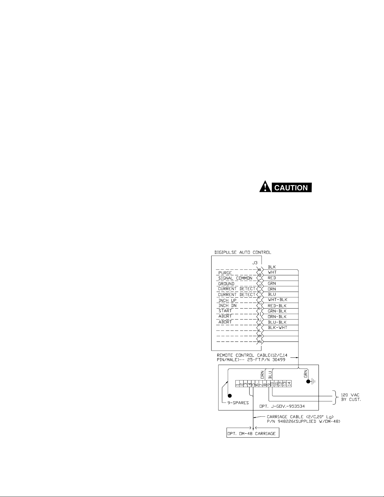
5. Remote Control Cable (J3) Assembly; 25-ft. long, P/N
30499. This assembly allows you to connect remote con-
trol functions (as shown on Fig. 1) such as Up/Down coldwire Inching, Welding Start-Stop, Weld Abort Output signal (to shutdown a carriage or fixture drive mechanism),
Weld Current Detector signal (to initiate a carriage or fixture drive mechanism), and a Purge/Reset (to “purge” the
shielding gas line of the torch, or to “reset” the welding
sequence after an abort shutdown occurs). The cable assembly consists of a 25-ft., 12 conductor cable with a 14pin male amphenol plug on one end and self-lead wire
connections at the other end.
6. Reel/Spindle Support, P/N 634288. This support arm is
utilized to mount either wire spools or coils. Will mount to
any fixture or to the OM-48 carriage when the required
support adaptor P/N 996498 is used.
7. Spindle Assy., P/N 948259. Mounts to Item 6 above and
is used for 12-in. diam. spools.
ter-cooled torch operation is to be used with the plumbing box, the jumper splice (between J5-E and -F) must
be disconnected because these pin locations will be
connected across the water pressure switch in the
plumbing box. Also note that pressure switch is factory
connected for normally- closed (N/C) operation, and must
be reconnected for normally- open (N/O) operation as
shown in Fig. 1.
13.OM-48 Carriage/J-Governor Packages. The OM-48 is
available in two different speed ranges, P/N 01E52 with a
43- 112 IPM travel speed range and P/N 01E54 with a 2 56 IPM speed range. Both packages include a solid state
J-Governor for speed control. The Remote Control Cable,
Item I-C-5 is required to connect the control to the J-Governor. Carriage track is not provided with the OM-48 packages but, is available in ten foot (10') lengths under P/N
38V16. An optional J-Governor digital travel speed meter
P/N 14292 is available as a special customer order. Refer
to Figure 1-A for OM-48/J-Gov. wiring hook-up.
II. OPERATING INSTRUCTIONS
8. H.D. Spoke-Type Wire Reel, P/N 19V89. Mounts to item
6 above and is used for 65 lb. coils.
9. Spool Enclosure Kit, P/N 600240, covers and protects
12-in. spools from dust and moisture.
10.Wire Wiper. The wire wiper effectively cleans and lubricates the welding wire as it is being fed, thus providing
smoother wire feeding and longer conduit life. A complete
wiping assembly consists of a Felt Wiper (P/N 598537,
Pkg. of 10) and one of the Wiper Holders following:
a. Wiper Holder, P/N 598763, screws into the optional wire
straightener.
b. Wiper Holder, P/N 598764, screws on to the accessory
support's inlet wire guide.
11.WC-9 Coolant Recirculator, P/N 33540 (F-15-140), is
used for water cooled torch operation and is designed to
be “free standing” in a convenient location near the torch.
A four-gallon capacity tank provides 1.0 gal/min @ 50 psi,
115/230 volts, 50/60 Hertz, 1 phase input. Since the cooler
is designed to run continuously during a welding operation, never connect it to a power supply or wire feeder that
uses a solenoid controlled water supply that opens and
closes with each operation of the welding contactor -- the
cooling efficiency of the unit will be hampered and the starting winding in the pump motor may burn out.
12.Plumbing Box, P/N 677261. The plumbing box assembly
contains the solenoid valves which provide shielding gas
and cooling water control. It is also equipped with a pressure switch in the water line which (if connected) will shut
down the welding operation when the water supply is
inadequate.u The Plumbing Box Control Cable, Item I-C-3
is required to connect the control to the Plumbing Box.
Refer to Figure 1 for Plumbing Box wiring hook-up.
Never, under any circumstances, operate the power supply with the cover removed. In addition to the safety hazard, improper cooling may cause damage to internal components. Keep side panels closed when unit is energized.
Also make sure you are adequately protected before you
start welding - welding helmet, gloves, eye and ear protection should always be worn.
K
As shipped from the factory, the digipulse control is wired
for air-cooled torch operation and this is provided by an
insulated jumper splice connection between pins J5-E & F of the control's plumbing Box receptacle J5. When wa-
Fig. 1A, OM-48/J-Gov. Carriage Hookup
7
Page 8

NOTES:
1. Both output welding cable leads (torch and work) must be a minimum size of No. 4/0 welding cable (nothing smaller), and both leads should be
kept as close to the same length as possible — with neither lead exceeding 50-ft. in length. Also, both cables must be run next to each other and
tywrapped every couple of feet to minimize cable reactance.
2. If wire feed runs backwards, reverse motor direction as follows: In the control, disconnect the blue wire (RLY-7) from T1-5 and connect it to T16; disconnect orange wire (RLY-9) from T1-6 and connect it to T1-5.
3. As shipped from the factory, the Digipulse control is wired for air-cooled torch operation and this is provided by an insulated jumper splice
connection between pins J5-E and -F of the control’s plumbing box receptacle J5. When water-cooled torch operation is to be used with the
plumbing box, the jumper splice (between J5-E and -F) must be disconnected because these pins will be connected across the water
pressure switch in the plumbing box. Also note that the pressure switch is factory-connected for normally-closed (NC) operation, and must
be reconnected for normally-open (NO) operation as shown above and in the schematic and detail wiring diagrams.
Figure 1 - Interconnection Diagram
8
Page 9

Do not allow metal-to-metal contact between the wire
feeder chassis and a metal surface connected in any way
to a welding ground. With such contact, a poor welding
ground connection may create a difference in potential
that sends part of the welding current through the safety
ground wiring in the control cable and wire feeder, resulting in burnout of that wiring and/or damage to wire
feeder circuitry. If the safety ground burns out, the operator may be exposed to 115V. shock hazard.
A. POWER SUPPLY WELDING CONTROLS
For detailed information regarding the power supply welding
controls, refer to F-15-014.
B. DIGIPULSE FRONT PANEL CONTROL FUNCTIONS
For location of front panel control features, refer to Figure 2 following:
1. Power Switch. Pulling-out the mushroom-style red button
of this switch turns power on into the control as indicated
5c
(Ref)
Key
Lock
5a
6
DIGIPULSE AUTOMATIC
MICROPROCESSOR CONTROL
a. Prior to starting the welding sequence, it actuates
the gas solenoid and lets you “purge” the shielding gas
line of the torch. At the same time, the IPM and VOLTS
windows will also display the preset times (in cycles)
for gas preflow and gas postflow respectively.
b. After starting the welding sequence -- if an abort
“shutdown” condition occurs (indicated by flashing digital
display), the Purge/Reset rocker can be actuated and
the control will automatically “reset”.
3. Inch-Up-Down Rocker. This switch is used to “cold inch”
the wire, up or down, at a preset speed which is programmed from the inside control panel (see II-C-4).
IMPORTANT: Cold inching is only possible when the weld
Start-Stop rocker switch is in its “stop” (or
off) position.
4. Start-Stop Rocker. This two position (no neutral) switch
initiates the welding sequence when placed in its START
position; and, depending on the type of welding -- Continuous Seam or Timed, terminates the welding sequence
in its STOP position as follows.
a. Continuous Seam welding applications. The “stop” sig-
nal does not immediately terminate the welding sequence, it only terminates the weld condition parameter. The sequence then transfers to the remaining condition parameters (crater fill, burnback, postflow/retract).
b. Single or Repeat “Timed” welding applications. Although
the “stop signal” is not normally used for timed-welds,
you may wish to prematurely terminate a burn thru or
unstable weld condition. When the “stop” is used; all
welding action (including crater-fill) will terminate, except burnback and postflow/retract.
5b
7
1
2
3 4
Fig. 2 Front Panel Controls
by the illuminated display windows. To turn power off, simply push-in red button and the display windows and control will deenergize.
NOTE: Immediately after the control is turned on a num-
ber will appear in the IPM window (e.g. 3) and
another number will appear in the VOLTS window, and these numbers will only be displayed
for 1-second. This information identifies the EProm “program” used in your control. The number shown in the VOLTS window will be in decimal form (e.g.,.1,.2,.3 etc.).
2. Gas Purge/Reset Rocker. A momentary “on” switch, this
rocker provides a dual function when actuated.
5. Digital Readout Windows. Three individual 3- digit windows labeled AMPS (optional ammeter), IPM and VOLTS
are provided to display actual welding current, preset or
actual welding parameters (wire feed speed and welding
voltage) and time parameters as follows:
a. AMP Digital Readout. This window is normally blank
unless the optional Ammeter Kit is provided to monitor
actual welding current. When installed, the window displays d.c. current (AMPS) in a range from 0-999 amperes in one amp increments.
b. IPM Digital Readout. This window is primarily used to
display wire feed sped (IPM) for each of the four “welding conditions” (Strike, Start, Weld, and Crater) during
a typical welding sequence. Depending on the position
of the inside “condition” selector switch functionally defined in II-C, the IPM window displays actual and/or preset wire feed speed in a range from 20 to 999 inches-
per-minute, in one-inch increments, for each weld condition in the program sequence.
l With power turned ON, but not welding, the IPM
window will “continuously” read the Preset wire
speed setting. When the arc is struck, the IPM window will then continuously read the Actual welding
wire speed as the weld conditions cycle thru the
welding sequence.
In addition to the above, and using the “Condition” and “Time/
Wire Dia.-Material” selector controls on the inner panel func-
9
Page 10

4
1
6
2
7
Figure 3 - Inside Panel Controls
tionally defined in II-C, this window can also display the following programmed times:
- PREFLOW. Shielding gas time from 0 to 999 cycles (16.5
sec.) in one cycle increments (60 cycles per second).
- START TIME. Start time duration is factory preset at 6
cycles, and can be increased up to 999 cycles, in one cycle
increments.
- WELD TIME. Weld condition duration for “timed-welding”
(must be set to zero for Continuous-Seam Welding), from
1 to 999 cycles, in one cycle increments.
- CRATER TIME. Crater fill duration, from 1 to 999 cycles, in
one cycle increments.
- MISSWELD TIME. Presets the number of cycles of arc
time that can reasonably be missed (from 1 to 999 cycles)
during the WELD condition and still produce an acceptable weld. If the number of missed cycles match the preset cycles, the unit will abort. Since the number of missed
cycles to be preset is based upon many variables, the required setting for a given application obviously involved
good judgment and technique. As an example, to set up a
critical 45 cycle spot weld, you might want to preset no
more than 5 cycles of missweld arc time. Be careful not to
make the missweld time to short, otherwise nuisance aborts
will occur. If this feature is not desired, preset the time for
zero cycles.
- INCH. Cold wire inch sped from 50 to 999 inches-perminute, in one inch increments.
- a code number indicates a type of MATERIAL which is
programmed for various welding wire applications, as follows: code #1 indicates Carbon Steel, #2 is Alternate Steel,
#3 is 4043 Aluminum, #4 is 5356 Aluminum, #5 is 308 Stainless, #6 is Silicon Bronze. (Additional Material code num-
bers 7 thru 10, are reserved for custom applications.)
- if provided, Ph indicates PULSE HEIGHT which is displayed
as a “reference voltage” setting, from 0.1 to 10 (in 0.1 volt
increments), that controls or establishes the amplitude of
the pulse peak (in teach option only).
3
5a
- if provided, Pb indicates PULSE BACKGROUND which is
displayed as a “reference current” setting, from 15 to 100
(in one ampere increments), that establishes the approximate background current in pulse applications (in teach
option only).
c. Volts Digital Readout. In a typical weld sequence, with
power “on” but not welding, this window will selectively
display an arbitrary number (100) that represents a programmed arc length in the “synergic” mode*, or a computed arc voltage in the “adaptive” mode* for each of
the four “welding conditions” (Strike, Start, Weld, and
Crater). When the arc is struck, the VOLTS window will
continuously display actual welding voltage in a range
from 12 to 50 vdc in one-tenth (0.1) volt increments.
* In the “synergic” mode , the control will automati-
cally select and display an appropriate “arc length”
integer for a given wire type, size, feed rate and gas
shielding. An arbitrary number, represented by the
integer 100, is the normalized value for all applications programmed in the control, and this figure will
be displayed in the VOLTS window during setup (not
welding). This value (set @ 100) can be readjusted,
within a range from 0 to 200, to fine-tune the operating arc length of the selected welding condition.
By reducing the number below 100 (minimum 0),
you will reduce the arc length. Conversely, by increasing this value above 100 (maximum 200) you
can increase the arc length. After the arc is struck,
the number will be replaced by the actual welding
arc voltage.
The Digipulse can also operate in the adaptive mode,
where the arc is continuously monitored by a closed
loop feedback circuit and the machine modulates
5b
10
Page 11

its output to maintain a given voltage for
preprogrammed data. In the adaptive mode, a computed arc voltage (unique to your preprogrammed
welding selection) will be displayed in the VOLTS
window before welding. Once the arc is struck, the
control will measure the actual welding voltage and
change the output of the power supply to maintain
the precalculated voltage setting. In this manner,
the power supply automatically compensates for
variations in stickout or weld joint geometry. Further, all of the precalculated arc voltages programmed in the control can be readjusted +/- 10
volts to “fine-tune” the welding arc.
In addition to the above, and using the inside “Condition” and
“Time/Wire Dia.-Material” selector controls (functionally defined in II-C), this window can also display the following programmed times.
- POSTFLOW. Controls time for gas postflow after the arc
extinguishes form 0 to 999 cycles.
- STRIKE TIME. Preset time period allowed, for the wire to
come down and hit the plate during the Strike Condition. If
the wire does not strike the plate within the allowed time
period, the control will automatically shutdown, and flash
the “strike time” in the VOLTS display window. Simultaneously, it also provides an abort output signal to stop carriage or fixture travel. Time range is factory preset for a
minimum of 20 cyclesl and can be increased in one cycle
increments.
played as a “frequency (Hertz) reference” setting, from 25
to 909* pulse cycles per second, that establishes the approximate pulse frequency required for the wire feed speed
set on the control (in teach option only).
* Please note that the maximum Pulse Frequency is de-
pendent on the “pulse width” - the narrower the width,
the higher the maximum frequency; and the wider the
width, the lower the maximum frequency.
6. Welding Condition (LED) Lights. These lights are labeled
START, WELD, and CRATER, and they energize individually as the welding program sequences through each of
these weld conditions. Prior to the Start, and after the Crater Conditions, none of these lights will be “on”.
7. Reset Circuit Breaker. A seven (7) ampere circuit breaker
provides protection to the 115 volt control circuit and the
wire feed motor. If an overload occurs, the breaker will trip
and suspend all operation. To restore service, simply depress the breaker button on the front panel.
C. INSIDE PANEL CONTROLS
For location of inside panel controls, see. Fig. 3.
1. Short (arc), Spray (arc), Pulse, optional Teach Mode
Schedule Selector. This four-position rotary switch allows
you to select the welding process mode you wish to use-non-pulsed mig Short or Spray Arc, or Pulsed mig spray
arc, and/or Teach mode (with teach option only) for “selfdeveloped” Synergic Pulsed mig spray arc applications.
l
The strike time setting is dependent upon the “strike
IPM setting”. The lower the speed, the longer the strike
time needs to be, otherwise nuisance shutdowns will
occur.
- BURNBACK TIME. Manually adjustable burnback time period which when preset will over-ride the automatic adaptive anti-stick feature. This time period can be set in one
cycle increments. When set to “zero”, the Automatic Adaptive Anti-Stick feature will be operational.
- REPEAT TIME (or Pause Time). Time period preset between timed- welds from 1 to 999 cycles, in one cycle increments.
- RETRACT TIME. After the postflow cycle, the wire feed
motor will reverse for automatic wire retract for a preset
time period. A setting of 10 to 30 cycles is recommended
to prevent excessive withdrawal of the wire into the contact tip. If a normal stop is desired, preset this time for zero
cycles.
- ARC HOURS. Selectable display (record) of accumulative
welding time in one tenth of an hour increments. After 99.9
hours it will automatically return to zero.
- a pair of numbers represent WIRE DIA. sizes which are
programmed for selection as follows: #23 represents .023''
dia., and #30 is .030'' dia.; #35 is .035'' dia., #45 is .045''
dia. hard (3/64'' dia. soft) and #63 is .063'' (1/16'') dia.
- if provided, Pw indicates PULSE WIDTH which is displayed
as a “reference time” setting, from 1.0 to 10 (in one-tenth
millisecond increments), that measures or establishes the
width of pulse duration (in teach option only).
- if provided, Pf indicates PULSE FREQUENCY which is dis-
In the Short, Spray, or Pulse schedule modes, the operator must code the control to select any one of the
“preprogrammed” welding wire “Materials” and wire “Diameters”, and then set the desired wire feed speed (IPM)
for each of the four weld conditions (Strike, Start, Weld,
and Crater) required for the weldment--the control automatically provides the computed arc voltage parameters
to produce the necessary output for the process/conditions
selected.
The optional Teach schedule mode is used in conjunction
with the Teach Pulse Parameter switch (item C-7), and it
allows the operator to develop and store one complete set
of customized “pulsed-mig” parameters. These parameters
include a wire feed speed (ipm) and a Pulse Frequency
(PF) setting for each of the four weld conditions (Strike,
Start, Weld, and Crater) needed. The remaining teach parameters that must be programmed include a Pulse Background (PB) a Pulse Height (PH) and a Pulse Width (PW),
and these parameters are common to all four conditions.
The set-up procedure for using the “teach mode” is more
fully described in Section III-D of this booklet.
2. Condition Selector. This six-position rotary switch is used
to select two sets of parameters, Welding and Timing for
each of the available welding schedules (Short Arc, Spray
Arc, Pulse, or Teach).
a. Welding Parameters. The selector's primary function,
when used with the appropriate Inc./Dec. toggle, allows
you to preset and display (see II-B-5-b & c) the wire
feed speed (IPM) and computed arc voltage (VOLTS)
“weld” parameters for its first-four positions labeled --
11
Page 12

STRIKE, START, WELD, and CRATER. The fifth position of this selector has “no” label, but is the required
position used for presetting the Missweld and Retract
Time features. The sixth position of this selector, labeled
RUN, is the normal operating setting used after the control is fully programmed and ready for use. The IPM
and VOLTS l parameters, for each of the following “welding” conditions, are preset or adjusted using the INC./
DEC. toggle located directly below their respective digital
window displays.
- STRIKE. This condition sets the desired approach
speed of the wire before striking the workpiece, and
displays the computed voltagel needed to control
the short-circuit current for arc initiation.
- START. This condition can be used to set an appropriate wire speed and display the computed
l
voltage
parameter to create a “hot-start” to help
stabilize the arc (for its preset time) prior to the weld
cycle.
- WELD. This condition sets the desired wire speed
and displays the computed arc voltage
l
used dur-
ing the actual weld cycle.
- CRATER. This condition allows you to set a higher
or lower weld speed and/or displayed computed
arc voltagel (for a preset time period), depending
on the welding condition needed, to regulate the
weld termination size or crater-fill appearance at
the end of the weld.
l
In all Process modes (Short, Spray, or Pulse)
except Teach, the microprocessor “automatically” provides the correct arc voltage (in the
adaptive mode) or arc length/frequency (in synergic mode) for each welding combination -- for
additional information regarding the Adaptive
versus Synergic modes of operation, refer to
Section II-C-4.
b. Time Parameters. The secondary function of this se-
lector is to setup the “Time” parameters, located within
the charts adjacent to each of the weld conditions. These
“times” are preset by using the Times/Wire Dia.-Material selector (following).
3. Times-Wire Dia./Material Selector. This two-position, momentary “on”, toggle must be actuated in order to preset or
change the following parameters, or welding setups:
a. Access the “Time” Functions. This position actuates
the “timed-parameters” for the sequences shown in the
chart beneath each digital display window. These se-
quences are preselected by positioning the Condition Selector to the pair of time-parameters to be
programmed from its Strike, Start, Weld, and Crater
settings. To check or observe the time settings, actu-
ate the TIMES (up) position; and to set or change the
settings, simultaneously operate the INC./DEC. toggle
switch directly below the parameter (chart) being set -the time setting in cycles will appear in its digital display. The timed- parameters which can be programmed
in each display window are shown in Fig. 3, and were
previously described in Section II-B-5- b (IPM window)
and Section II-B-5-c (VOLTS window).
b. Access the WIRE DIA/MATERIAL mode (down posi-
tion) to select one of the welding conditions
preprogrammed into the control, as follows:
To select the type of wire MATERIAL, actuate the INC
position of the Inc/Dec switch below the IPM window
(while holding the Wire Dia/Mat'l key down) until the
desired code number for your “material selection” appears in the IPM window, and these material codes follow: #1 is carbon steel, #2 is alternate steel, #3 is 4043
aluminum, #4 is 5356 aluminum, #5 is 308 stainless,
#6 is silicon bronze. (Additional Material codes 7 thru
10, are reserved for custom applications.)
Now select the Wire DIA. size to be used, by actuat-
ing the INC position of the Inc/Dec switch below the
VOLTS window (while holding the Wire Dia/Mat'l key
down) until the desired pair of numbers for your “wire
size selection” appears in the VOLTS window, and these
wire diameter numbers follow: #23 is .023" dia., #30 is
.030" dia., #35 is .035" dia., #45 is .045" dia. hard
(3/64" dia. soft), and #63 is .063" (1/16" dia.).
NOTE: Accessing the WIRE DIA/MAT'L selector key “dur-
ing an actual weld,” allows you to check the factory- preset numbers that determine the quality
of starts (hot, cold, etc.) for your preset welding
condition. These numbers are preset to provide
optimum starting characteristics required for
most welding applications. This is a diagnostic
tool available to the experienced operator or serviceman and need not be activated during a normal operation unless you are experiencing weld
starting problems, or weld condition (speed and/
or voltage) aborting problems. It must also be
noted that only the speed (IPM) condition can be
checked when a unit is operating in the “synergic mode” (the VOLTS window will always displayed the number “100” and cannot be adjusted;
however, in the “adaptive mode” both speed and
voltage conditions can be checked and adjusted.
The factory-set “starting condition” is represented by numbers that are displayed, on command, in the digital IPM and VOLTS windows. For
good welds and starts, these numbers should
be in a range from 105 to 115 (with 110 being the
norm) in the IPM window (synergic and adaptive
mode), and from 90 to 100 (with 95 being the
norm) in the VOLTS window (adaptive mode
only). If your weld starts are not acceptable,
please refer Section III-C-10-b for a simple adjustment procedure that will enhance good starting.
4. Synergic-Adaptive-Inch Preset/Arc Hours Selector. This
switch provides three essential functions; depending on
the toggle-positions selected as follows:
a. The “toggle-down” location is a momentary on position
for checking or presetting a cold-wire INCH parameter
(50-999 ipm), or to monitor and reset the accumulated
ARC HOURS (welding) time. These features are only
functional when the control is in its non-welding mode.
To check or monitor this data, you must place the Con-
12
Page 13

dition selector switch in its RUN setting and toggle-down
the Inch Preset/A.H. function--the data will be displayed
in the IPM and VOLTS windows respectively. To set or
“zero” the data, place the Condition selector in its RUN
setting & actuate the Inch Preset/A.H. position while
simultaneously operating the Inc./Dec. switch below the
function being adjusted--this data will be displayed in
the appropriate IPM and/or VOLTS window.
b. The “toggle-center” location is a maintained ON posi-
tion for operating the control in the ADAPTIVE* logic
mode. The Adaptive logic utilizes a closed loop feedback system that continuously modifies the output to
maintain a constant arc voltage. The “adaptive operation” works as follows:
Pulse Arc Welding: Adaptive welding is a synergic relationship programmed into the weld control which will
calculate and display the proper arc voltage for a given
wire feed speed and material setting (see graph). As
the wire feed speed increases the control will automatically increase the pulse frequency to maintain the arc
voltage set in the control VOLTS window. Changes in
tip to work will not affect arc length.
voltage is set-up by the weld control program and
changes in tip to work will effect arc length. The voltage
can be read during welding and increased accordingly
to obtain a stable welding condition based on the wire
feed speed used. If the wire feed speed is changed,
the program will calculate the new voltage necessary
to maintain a stable arc.
* Please note that either type of logic (adaptive or syn-
ergic) can be used in the “preprogrammed” material
codes; however, only the synergic logic can be used
in the optional “Teach” process mode.
5. Inc/Dec Toggle Switches. These two control toggles are
used to preset or change the individual welding “Condition” parameters required for the selected “Process” mode
(Short, Spray, Pulse, and Teach). The switches are spring
loaded, center-return toggles which must be operated (Inc
or Dec) to actuate their indicated functions as follows:
Spray Arc and Short Arc: In this mode the machine
will control the power supply to maintain the arc voltage
set-up in the volts window of the control. Changes in tip
to work will not change arc length. The voltage can be
preset before welding and changed during welding to
obtain a stable welding condition based on the wire feed
speed used. If the wire feed speed is changed then the
program will calculate the new voltage necessary to
maintain a stable arc.
c. The “toggle-up” location is a maintained ON position
for operating the control in the SYNERGIC* logic mode.
The Synergic program logic provides the weld process
modes with fixed operating parameters that follow
preprogrammed relationships. The “synergic operation”
works as follows:
Arc Length Will Not Change
with Tip to Work Distance
Arc Volts
Frequency Changes
with Tip to Work Distance
Wire Feed (ipm)
Pulse Arc Welding: Synergic welding is a relationship
of pulse frequency and wire feed speed (see graph)
programmed into the weld control. As the wire feed
speed increases the control will automatically increase
the pulse frequency to maintain stable weld performance. Changes in welding current (heat) can be completed by increasing or decreasing the IPM switch without readjusting voltage. Changes in tip to work will affect arc length.
Spray Arc and Short Arc: In this mode the machine
will operate like a conventional welder where an arc
Arc Length Will Change
with Tip to Work Distance
Frequency Does Not
Change
with Tip to Work Distance
or
Arc Volts
(Spray/Short)
Pulse Frequency
Wire Feed (ipm)
a. “IPM-TIME” Increase/Decrease Control. This toggle
switch is used to set and/or vary wire feed speed (IPM)
for the required “weld conditions” (Strike, Start, Weld &
Crater), and also the following: Material-type, Preflow
(time), Start Time, Weld Time, Crater Time, Missweld
Time and Inch Preset (ipm), and Pulse Height (PH) and
Pulse Background (PB) in the optional teach mode. By
setting and/or operating the appropriate Control Selectors (see C-2 and -3 above), each parameter setting
will be displayed in the digital window directly above
this toggle.
b. “VOLTS-TIME” Increase/Decrease Control. This
toggle switch is used to set and/or vary the arc voltage*
(VOLTS), for the required “weld condition” (Strike, Start,
Weld & Crater), and also the following: Wire Diameter,
Postflow (time), Strike Time, Burnback Time, Repeat
Time, Retract Time and to “zero” (dec.) the Arc Hour
accumulation, and Pulse Width (PW) and Pulse Frequency (PF) in the teach mode. By setting and/or operating the appropriate Control Selector (see C- 2 and -3,
above), each parameter setting will be displayed in the
digital window directly above this toggle.
* Please note that the term VOLTAGE denotes “arc voltage”
(in the adaptive mode) and/or “arc length” (in the synergic
mode) and is the computed value that has been
precalculated for each of the combinations programmed
into the control. And further, any of these “computed voltages” can be altered (+/- 5 volts in the adaptive mode; and
+/- 50 numerals from its midrange value of 100 in the synergic mode) to fine tune each welding condition (Strike,
Start, Weld, & Crater).
13
Page 14

However, when a condition (e.g.: the Strike Condition) is
altered, the computed value is altered for all other
precalculated wire size/type combinations available in that
condition--the computed values for the remaining conditions (Start, Weld, Crater) are not affected unless they also
are altered. Therefore, when you plan to use a new com-
bination (a different wire size and/or type), it is suggested that the control be “reset” to provide the correct
computed value for the new program combination as follows:
Adaptive Mode. To reset the computed arc voltage value
for a given wire size and type, make sure the control's
Power switch is “on” and the unit is not in a welding mode,
then decrease the arc voltage key until the number in the
VOLTS window stops. This number is 5 volts below the
computed or midrange value. To establish the computed
value, add 5 (volts) to the displayed number using the increase (INC) portion of the Volts Inc./Dec. key.
Synergic Mode. Resetting the computed value in this
mode is much simpler--remember that the computed or
midrange value is the arbitrary numeral 100 (this number
represents a precalculated “arc length/frequency” based
on the wire feed speed of the programmed wire size and
type). Therefore, if the number appearing in the VOLTS
display window is any numeral between 50 and 150 (other
than 100) simply use the appropriate Inc./Dec. key to reset the condition to the numeral 100.
6. Amp Test-Weld Switch. This two-position toggle switch
provides the following functions:
a. The WELD position is the normal and required setting
for all schedule welding operations.
b. The AMP TEST position is only used to provide a con-
venient way of “test-sequencing” all of the program parameters to either diagnose a problem, or to demonstrate the control without actually striking a welding arc.
The test can be set up with the control operated in any
of its preprogrammed schedule modes (Short, Spray or
Pulse) that have a complete set of actual welding parameters preset, except for the “Missweld” time which
must be set to “zero”--otherwise an abort will occur.
With this accomplished, make sure that the welding wire
is clear of the workpiece/weldment and then open up
the accessory support (on the welding head) to release
pressure on the wire feed roll. Now place the Start-Stop
rocker switch (on the front panel) to its START position,
and the control will sequence thru the programmed
Preflow-time and enter the Strike condition--Remem-
ber that open-circuit or welding voltage is present
on the welding wire during the test sequence.
Make sure that the Strike Time is set long enough to
give you ample time to operate the “Amp” test toggle (a
setting of 200 cycles is recommended for the Strike
time).
During the Strike condition; you must actuate the “Amps”
toggle to its TEST position, to simulate closure of the
arc/current detection circuitry that verifies the arc has
initiated. This action automatically allows you to enter
the timed Start condition, and the subsequent Weld,
Crater, etc., conditions to evaluate and/or demonstrate
the welding sequence.
7. Teach Pulse Parameter Selector PH, PW, PB, PF (in
“teach” kit only). This momentary two-position switch is
only operative when the process (Short/Spray/Pulse/Teach)
control selector is placed in the Teach mode position (see
Item II-C-1). When the Teach Parameter switch is actuated, it allows you to program one complete set of customized (self-developed) pulsed- spray arc mig parameters. The subsequent teach parameter settings for Pulse
Height (PH) and Pulse Background (PB) are displayed in
the IPM window (and described in Section II-B-5-b); and
Pulse width (PW) and Pulse Frequency (PF) are displayed
in the VOLTS window (previously described in Section IIB-5-C). Please note that a Pulse Frequency (PF) parameter must be programmed for each wire feed speed (ipm)
setting selected for use in each of the four welding conditions (Strike, Start, Weld, and Crater). The remaining teach
parameters PH, PB, and PW are common to all four weld
conditions, and therefore only need to be programmed once
(for example, in the Strike mode). The set-up procedure
for the “teach mode” is fully covered in Section III-D.
III. SETTING UP PROGRAM PARAMETERS
A. GENERAL WELDING PROGRAM DATA
Four sets of welding (schedule) mode parameters can be preset in the Digipulse control: one each for the standard SHORT
arc, standard SPRAY arc and one for the PULSE (spray) arc
schedule modes using any one of the “preprogrammed” wire
material/diameters parameters; and one for the optional Teach
(pulse) schedule mode, which incorporates the customer's
“self- developed” pulsed welding parameters.
Because of the distinct differences between the
“preprogrammed” welding parameters (for the Short/Spray/
Pulse schedule modes) and the “self- developed” welding parameters (for the pulsed Teach schedule mode), the specific
“set-up procedures” for Short/Spray/Pulse control parameters
are covered in Section C, and the optional Teach control parameters in Section D following.
Since proper gas shielding is extremely important in conventional and pulsed welding applications, we have also provided
a list of recommended shielding gases (Table II-following) suggested for use with the wire material preprogrammed in this
control--however, you may find other combinations that are
equally successful.
B. PRELIMINARY POWER SUPPLY CHECKS
Before programming the control, make sure that the
power supply is properly set-up as follows:
- Check the rear panel of the power supply to make sure
that only the “Digipulse control cable” is connected. The
remaining “stick control receptacle/cable” must be dis-
connected.
- Depending on the welding process mode programmed on
the control, set the power supply INDUCTOR control pot
as follows:
14
Page 15
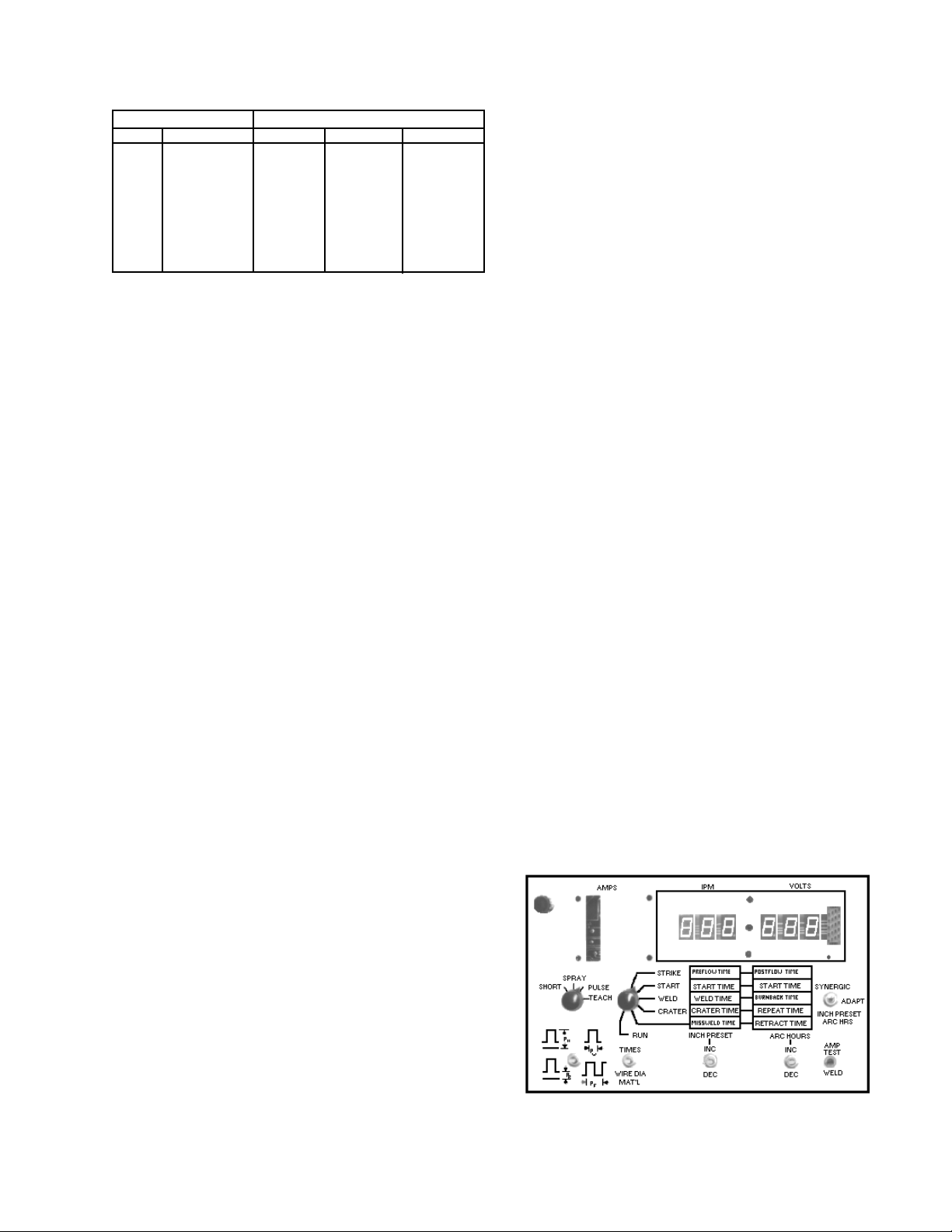
Table II
Recommended Shielding Gas
Wire Material Welding Arc Mode
Code # Type Short Arc Spray Arc Pulse Arc
1 Carbon Steel CO
2 Alternate Stl. C-25 Stargon/C-8 Stargon/C-5
3 4043 Aluminum - Argon Argon
4 5356 Aluminum - Argon Argon
5 308 Stainless A1025 1%/2%O
6 Silicon Bronze - Argon Argon
7*
8*
9*
10*
* These codes are reserved for custom applications.
/C25 C-5/C- 8 C- 5
2
Pulse SS
2
For SHORT ARC mode, set Inductance @ 12 O'clock position and adjust for best performance when welding.
For PULSE and SPRAY ARC and TEACH modes set Inductance @ MINIMUM.
C. PROGRAM CONTROL PARAMETERS FOR SHORT/
SPRAY/PULSE WELDING PROCESS MODES
The following procedures represent a typical example of how
to set up one of the many “preprogrammed” welding material
conditions available in this control, and that these procedures
can be used in each schedule mode--Short, Spray, and Pulse.
The only difference(s) between each “schedule mode” will,
or may, be the Wire Material and/or Wire Diameter used, the
IPM wire feed speed setting for each weld condition (Strike,
Start, Weld and Crater), the pair of Time parameters for each
weld condition, and the shielding gas used--the control automatically provides the required arc voltage for each weld condition, and even this parameter (voltage) can be fine-tuned
as described following.
1. Pull the POWER switch button to its “out” position to energize the control for programming.
2. On the inside panel, set the SHORT-SPRAY-PULSE mode
selector switch to the “process” you wish to preset.
3. Make sure the inside Amp Test toggled switch is in its WELD
position.
4. Select the type of Wire Material and Wire Diameter to be
used as follows. Depress and hold the WIRE DIA./MATERIAL toggle switch in its “down” position and simultaneously
preset each of the following:
a. Set the STRIKE “wire feed speed” (IPM) by operating
the “left” Inc./Dec. toggle until the desired setting appears in the IPM display window. Notice that this parameter setting will start at zero and immediately jump
to 20 and then rapidly increase (1 ipm at a time) until
the desired setting is reached. If you overshoot the
planned setting, simply “bump” the DEC position of the
left toggle to obtain the exact IPM setting.
b. As mentioned previously, after the welding condition in
items 4 and 5-a (above) have been preset, the microcomputer automatically sets a preprogrammed arc voltage (in the adaptive mode) or arc length/frequency (in
the synergic mode) for the STRIKE condition will be
displayed in the VOLTS window. If this precalculated
valuel (voltage or frequency) does not provide a stable
condition it can be fine-tuned by using the “right” Inc./
Dec. toggle switch--as described in Section II-C-5-b.
l
If the existing welding condition is altered (fine tuned),
it is suggested that each time a new wire size/type is
used that you reset the control to set up the original
computed (mid-range) arc voltage/frequency values as
described in Section II-C-5-b.
c. Leave the rotary selector in the “STRIKE” position to
set the PREFLOW and POSTFLOW “time” parameters
(as shown in Fig. 4). Actuate the “Times-Wire Dia./Mat.”
toggle switch to its TIMES (cycle) position, and observe
that the existing numbers shown in the IPM and VOLTS
windows will change--the new parameters being the pair
of “time” functions in the chart(s) adjacent to the selected condition (in this case, the pre- and postflow data).
To reset or change these “Time” parameters (see Fig. 4);
actuate and hold the TIMES toggle position, while simultaneously operating the appropriate INC./DEC. toggle switch
below each of the time parameters being set. The preset
time intervals will be displayed in their respective IPM and
VOLTS digital windows.
6. Reposition the rotary Condition selector to the START position and program the following:
a. Set the START “wire feed speed” (IPM) using the same
procedure outlined in III-C-5-a.
b. The subsequent “arc voltage” or “arc length/frequency”
for the START condition will be set as outlined in III-C5-b.
a. Operate (increase or decrease) the “left” Inc./Dec. toggle
switch (beneath the IPM window) until the desired MATERIAL numeral (1-carbon steel, 2-alternate steel, 34043 aluminum, 4-5356 aluminum, 5-stainless steel,
6-silicon bronze) appears in the IPM display window.
b. Now, operate (increase or decrease) the “right” Inc./
Dec. toggle switch until the desired WIRE DIA. numeral
(#23 for .023", #30 for .030" dia., #35 for .035" dia., #45
for .045" dia., or #63 for .063" dia.) appears in the VOLTS
display window.
5. Place the rotary Condition selector to the STRIKE position
and program the following:
Figure 4, Typical Time Parameter Set Up
15
Page 16

c. Leave the rotary selector in the START position and set
the START TIME and STRIKE TIME parameters using
the procedures outlined in III-C-5-c.
7. Reposition the rotary Condition selector to the WELD position and program the following:
a. Set the WELD “wire feed speed” (IPM) using the same
procedure outlined in III-C-5-a.“
b. The subsequent “arc voltage” or “arc length/frequency”
for the WELD condition will be set as outlined in III-C-5b.
c. Leave the rotary selector in the WELD position and set
the WELD TIME and BURNBACK TIME parameters
using the procedures outlined in III-C-5-c, and also the
following:
(1) “WELD TIME” setting requirements for:
(a) Continuous Seam Welding--set time to
“zero”.
(b) Single Time Weld without carriage travel (cus-
tomer must deenergize the arc detection output
signal)--set time from 1 up to 999 cycles.
(c) Single Time Weld with carriage travel (the Arc
Detector Circuit provides a signal to initiate travel
of a carriage, or fixture)--set time from 1 up to
999 cycles.
(d) Repeat Timed Weld (same as c) except that the
elapsed time between welds is preset in the REPEAT TIME PARAMETERS.
(2) “BURNBACK TIME” setting requirements:
(a) If automatic adaptive anti-stick is desired--set
time to “zero”.
(b) If manual burnback (anti-stick) is needed--set
time required from 1 cycle on up.
8. Reposition the rotary Condition selector to the CRATER
position and program the following:
a. Set the CRATER “wire feed speed” (IPM) using the same
procedures outlined in III-C-5-a.
b. The subsequent “arc voltage” or “arc length/frequency”
for the CRATER condition will be set as outlined in IIIC-5-b.“
c. Leave the rotary selector in the CRATER position and
set the CRATER TIMEl and REPEAT TIMEll parameters using the procedures outlined in III-C-5-c.
l
If the Weld and Crater conditions are both “Timed”;
simply preset the appropriate time desired for each
condition - 1 up to 999 cycles for Weld, and 1 up to 999
cycles for Crater.
If the Weld condition is a Continuous Seam weld, the
CRATER condition can either be “Timed” or skipped
completely. If Crater Fill is desired; enter from 1 to 999
cycle in the Crater Time parameter. If Crater fill is not
desired; simply enter “zero” in the Crater Time parameter, and this sequence will be skipped after the STOP
switch terminates the Weld condition sequence.
ll
Repeat Time--if repeat “timed weld” are not used, set
this time to “zero”. If repeat welds are desired, the
cycles set will control the elapsed time between the
“Timed” weld parameters.
9. Reposition the rotary Condition selector to the “blank” position, and program the following:
a. Set the MISSWELD TIME
l
and RETRACT TIME pa-
rameters using the procedures outlined in III-C-5-c.
l
The Missweld time cycle only monitors the WELD Condition. If not desired, set Missweld Time to “zero”.
10.Reposition the rotary Condition selector to the RUN position to perform the following operations:
a. To check or preset a cold-wire INCH parameter (50-
999ipm), or to monitor or “zero” the accumulated ARC
HOURS (welding) time. (These features are only functional in a non-welding mode.) To check or monitor
this data, you must place the Condition Selector switch
in its RUN setting and actuating the Inch Preset/Arc
Hrs. switch position*--the “data” will be displayed in the
IPM and VOLTS windows respectively. To set or “zero”
the data, place the Condition Selector in its RUN setting and actuate the Inch Preset/Arc Hrs. switch position* while simultaneously operating the Inc/Dec switch
below the function being adjusted--this data will be displayed in the appropriate IPM and/or VOLTS window.
* This momentary switch position (Arc Hrs/Inch Preset)
is part of the SYNERGIC-ADAPTIVE-ARC HRS/INCH
PRESET switch (covered in Section II-C-4). After the
control is fully programmed, the operator must set either the SYNERGIC or ADAPTIVE position to determine
the “program logic” that the control will utilize for the
programmed schedule sequence.
In the synergic mode, the control selects an appropriate arc length, based on weld mode (short, pulse or
spray), for a given wire type, size and feed rate. The
pulse frequency in pulse mode remains constant regardless of torch manipulation. This pulse logic offers
many advantages to the welder particularly where joint
geometry cause rapid changes in torch stickout resulting in unstable puddle conditions.
In the adaptive mode, the control varies the frequency
during pulse welding to maintain a constant arc voltage regardless of changes in torch stickout or angle.
This logic is very useful where joint geometry is clean.
b. The RUN position is the “normal operating setting” used
when the control is fully programmed and ready to be
weld- tested, and if necessary readjusted. If your weld
starts are not acceptable, refer to the following “Hot Start”
adjustment procedures that will enhance starting.
Hot Start Adjustment Procedures
As mentioned earlier in the italicized “Note” following Section
II-C-3-b, the control is preset at the factory to provide the optimum starting characteristic for most welding conditions. However, due to factors such as inaccurate parameters (for a given
wire type and size), welding technique, shielding gas, or wire
feed speed, you may have to readjust the factory-set starting
characteristics to provide the best arc starts possible. To do
this, it is necessary to readjust the factory-set calibrations to
provide a hot start characteristic in which the initial starting
voltage (open- circuit voltage) will be slightly higher than ac-
16
Page 17

tual welding voltage (arc voltage) and speed which initially is
somewhat lower than the selected wire feed speed desired.
To set-up the control to provide this, do the following:
Program the welding condition you need in the IPM (wire feed
speed) and VOLTS( arc voltage) windows, and fine-tune these
parameters until you have the welding arc desired. Do not at
this point concern yourself with the “arc starts”, this follows.
If after the welding condition is fine-tuned you find that the arc
starts are unsatisfactory, proceed as follows:
(1) During an actual weld, actuate and hold the Wire Dia/
Mat'l. key position and observe the numbers displayed
in the IPM and VOLTS windows.
Remember that only the speed (IPM) condition can
be checked when a unit is operating in the “synergic
mode” (the VOLTS window will always display the number “100” and cannot be adjusted); however, in the
“adaptive mode” both speed and voltage conditions
can be checked and adjusted.
(2) For proper starts, the number in the IPM window should
be in the range from 105 to 115. If it is not, adjust the
Inc/Dec toggle (below the IPM window) until the displayed number reads 110.
(3) Similarly, the number in the VOLTS window should be
in the range of 90 to 100. Again, if it is not, adjust the
Inc/Dec toggle (below the VOLTS window) until the
displayed number reads 95.
(4) These adjustments to the control should now provide
good arc starts to a legitimate welding condition.
(5) A good “rule-of-thumb” to follow whenever you set up
a new welding condition and you experience unstable
starts, is to simply check the start characteristic numbers (while welding) to make sure they are within the
ranges described in the preceding steps.
If you continue experiencing problems, refer to Troubleshooting procedures.
The following instructions assume that the operator is familiar with “pulse-mig” welding and the effects of pulse variables
with respect to arc performance.
The Pulse Height, Width, and Background parameter settings
(derived from the appropriate pulse parameter graphs) need
only be set once, in the STRIKE condition, because they are
common to all other weld conditions (START, WELD and CRATER). The Pulse Frequency parameter setting (also derived
from the appropriate graph examples) must be programmed
for each wire feed speed set in the IPM window for each weld
condition (Strike, Start, Weld & Crater). The metal transfer
and arc characteristics are defined by pulse height (PH), width
(PW) and background current (PB). These parameters, shown
in Figure 5, must be developed for each wire type, diameter,
shielding gas, and stickout. To maintain the proper arc characteristics once an appropriate pulse height, width and background have been established, the pulse frequency should
be the only parameter requiring readjustment with changes
in wire feed speed to maintain a stable arc condition. The
“teach” mode operates in the synergic logic “only” (not
adaptive), and only one wire feed speed and its respective
pulse frequency setting can be programmed in each weld
condition (Strike, Start, Weld, and Crater). Changes in wire
feed speed will require a manual adjustment to the pulse
frequency to maintain stable metal transfer. Since the op-
erator selects pulse parameters at a given point, the control
will not assume values at other wire feed speeds.
For the inexperienced operator, use the following graphs to
assist in pulse parameter set-up. These graphs will provide
you with pulse parameters used in the preprogrammed codes
(1-6). To obtain specific arc characteristics these parameters
can be set- up and changed in the teach mode. The following
procedure will achieve a reasonable starting point for pulse
welding in each “weld condition” (Strike, Start, Weld, and Crater).
1. Pull the POWER switch button, on the front panel, “out” to
energize the control.
2. Make sure the Amp-Test toggle switch (Item 2, Fig. 6) is in
WELD position.
D. PROGRAMMING YOUR OWN PULSE PARAMETERS IN
TEACH MODE (with Teach option kit).
The “teach” mode program is designed to allow the operator
to develop and store one set of customized Pulsed mig parameters* for wire types which have not been preprogrammed
in this control (for example; titanium, inconel, monel, etc.). In
some instances the preprogrammed carbon steel or stainless steel parameters may be inadequate, and the “teach”
mode can then be used to further refine those particular arc
characteristics.
* You may wish to permanently incorporate your “selfdeveloped” conditions in codes 7 thru 10 which are reserved for custom applications. If so, you can specialorder a custom E-PROM, from ESAB, that will include your
teach conditions along with the other preprogrammed
applications. In order to do this, you will have to provide
the necessary welding condition development parameters
outlined in Section E following.
Figure 5 - Pulse Wave Description
3. Set the Process control selector (Item 1, Fig. 6) in its
TEACH position.
17
Page 18

The selected Teach position automatically sets-up the control for Synergic pulse operation (and disables voluntary
selection of synergic/adaptive logic using toggle switch Item
3, Fig 6). At the same time, it “enables” the optional Pulse
Parameter program switch (Item 5, Fig. 6) to be operative
for programming the teach-pulse functions described following.
b. Using the pulse parameter graph(s), shown following
Step D-11, approximate the pulse Height*, Width* (for
step c), and pulse Background* and Frequency (for step
d) settings for the material type and diameter you plan
to use. Select the appropriate pulse parameter graph
which corresponds to the material type being used. For
wire types other than those shown, choose the graph
that comes closest to your wire type. For example, for
coppers use the silicon bronze graph parameters as a
starting point.
4
1
5
6
7
8
Figure 6 - Teach Set-Up On Inside Panel
4. When programming in the teach mode, you do not need
to enter a code number for Wire Diameter or Material (as
is required for pre-programmed data)--therefore it is not
necessary to actuate the Wire Dia./Mat'l toggle for this data.
IMPORTANT: Please note that all other parameters (one
complete set) that are programmed (follow-
ing) will be retained in memory (except for wire
size and type of material)--therefore, it is suggested that you document all wire data and
developed parameters relating to a particular teach application for future reference.
5. Place the rotary Weld Condition selector (Item 4, Fig. 6) to
the STRIKE position and program the following:
a. Set the STRIKE “wire feed speed” (IPM) by operating
the “left” Inc./Dec. toggle (Item 7, Fig. 6) until the desired setting appears in the IPM display window. Notice
that this parameter setting will start at zero and immediately jump to 20 and then rapidly increase (1 ipm at a
time) until the desired setting is reached.
* Please remember that these pulse parameter settings
(Height, Background & Width) are only set once, in the
STRIKE condition, and are then common for all remaining “Weld” conditions. Only the pulse Frequency and
wire feed speed parameter settings need be programmed for each “Weld” condition.
c. Program the Pulse Height (PH) and Pulse Width (PW)
parameters, from the material graph legend for the diameter wire installed, by “holding” the Pulse Parameter
switch (Item 5, Fig. 6) in its “up” position and the following:
(1) Set the selected Pulse Height (PH) parameter in
the IPM window using its Inc/Dec switch (Item 7).
The number in this window represents pulse height
from .1 to 10 volts (in 1/10 volt increments).
(2) Now, set the selected Pulse Width (PW) param-
eter in the VOLTS window using its Inc/Dec switch
(Item 8). The number in this window represents
pulse width from 1 to 10 milliseconds (in 1/10 millisecond increments).
d. Program the Pulse Background (PB) and Pulse Fre-
quency (PF) parameters, from the material graph legend for the diameter wire installed, by “holding” the
3
Pulse Parameter switch (Item 5, Fig. 6) in its “down”
position and the following:
2
(1) Set the selected Pulse Background (PB) param-
eter in the IPM window using its Inc/Dec switch
(Item 7). The number in this window represents
pulse background current from 15 to 100 amperes
(in 1 amp increments).
(2) Now, set the selected Pulse Frequency (PF) pa-
rameter in the VOLTS window using its Inc/Dec
switch (Item 8). The number in this window represents the approximated pulse frequency derived
from the graph for wire feed speed selected (step
5a) and is display in Hertz from 25 to 909 pulse
cycles/second.
e. Once an acceptable arc condition has been obtained
by further modifying pulse height, pulse width, and pulse
background, changes in wire feed speed will necessitate a manual adjustment to the pulse frequency to maintain a stable metal transfer.
f. Leave the rotary Condition selector in the “STRIKE” po-
sition to set the PREFLOW and POSTFLOW “time” parameters. Actuate the “Times-Wire Dia./Mat.” toggle
switch (Item 6, Fig. 6) to its TIMES (cycle) position, and
observe that the existing numbers shown in the IPM
and VOLTS windows will change--the new parameters
being the pair of “time” functions in the chart(s) adjacent to the selected condition (in this case, the pre- and
postflow date).
To reset or change these “Time” parameters, actuate
and hold the TIMES toggle position, while simultaneously operating the appropriate INC./DEC. toggle
18
Page 19

switch below each of the time parameters being set.
The preset time intervals will be displayed in their respective IPM and VOLTS digital windows.
6. Reposition the rotary Condition selector (Item 4, Fig. 6) to
the START position and program the following:
a. Set the START “wire feed speed” (IPM) using the same
procedure outlined in III-D-5-a.
b. Now set the selected Pulse Frequency (PF) for the
“START” wire feed speed using the same procedure
outlined in III-D-5-d-(2) & D-5-e.--Remember that the
remaining pulse parameters (Height, Background &
Width) are only set once, in the Strike mode.
c. Leave the rotary selector in the START position and set
the START TIME and STRIKE TIME parameters using
the procedures outlined in III-D-5-f.
7. Reposition the rotary Condition selector to the WELD position and program the following:
a. Set the WELD “wire feed speed” (IPM) using the same
procedure outlined in III-D-5-a.
b. Now set the selected Pulse Frequency (PF) for the
“Weld” wire feed speed using the same procedure outlined in III-D-5-d-(2) & D-5-e. -- Remember that the remaining pulse parameters (Height, Background &
Width) are only set once, in the Strike mode.
c. Leave the rotary selector in the WELD position and set
the WELD TIME and BURNBACK TIME parameters
using the procedures outlined in III-D-5-f, and also the
following:
(1) “WELD TIME” setting requirements for:
(a) Continuous Seam Welding -- set time to “zero”.
(b) Single Time Weld with carriage travel (customer
must deenergize the arc detection output signal) - set time from 1 up to 999 cycles.
(c) Single Time Weld with carriage travel (the Arc
Detector Circuit provides a signal to initiate travel
of a carriage, or fixture) - set time from 1 up to
999 cycles.
(d) Repeat Timed Weld (same as c) except that the
elasped time between welds is preset in the
REPEAT TIME parameters.
(2) “BURNBACK TIME” setting requirements:
(a) If automatic adaptive anti-stick is desired - set
time to “zero”.
(b) If manual burnback (anti-stick) is needed - set
time required from 1 cycle on up.
8. Reposition the rotary Condition selector to the CRATER
position and program the following:
a. Set the CRATER “wire feed speed” (IPM) using the same
procedures outlined in III-D-5-a.
b. Now set the selected Pulse Frequency (PF) for the “Cra-
ter” wire feed speed using the same procedure outlined
in III-D-5-d-(2) & D-5-e.-- Remember that the remaining pulse parameters (Height, Background & Width) are
only set once, in the Strike mode.
c. Leave the rotary selector in the CRATER position and
set the CRATER TIMEl and REPEAT TIMEll parameters using the procedures outlined in III-D-5-f.
l
If the Weld and Crater conditions are both “Timed”;
simply preset the appropriate time desired for each
condition 1 up to 999 cycles for Weld, and 1 up to
999 cycles for Crater.
If the Weld condition is a Continuous Seam weld,
the CRATER condition can either be “Timed” or
skipped completely. If Crater Fill is desired; enter
from 1 to 999 cycled in the Crater Time parameter. If
Crater fill is not desired; simply enter “zero” in the
Crater Time parameter, and this sequence will be
skipped after the STOP switch terminates the Weld
condition sequence.
ll
Repeat Time -- if repeat “timed weld” are not used,
set this time to “zero”. If repeat welds are desired,
the cycles set will control the elapsed time between
the “Timed” weld parameters.
9. Reposition the rotary Condition selector to the “blank” position, and program the following:
a. Set the MISSWELD TIMEl and RETRACT TIME pa-
rameters using the procedures outlined III-D-5-f.
l
The missweld time cycle only monitors the WELD Condition. If not desired, set Missweld Time to “zero”.
10.Reposition the rotary Condition selector to the RUN position to perform the following operations:
a. To check or preset a cold-wire INCH parameter (50-
999ipm), or to monitor or “zero” the accumulated ARC
HOURS (welding) time. (These features are only functional in a non-welding mode.) To check or monitor
this data, you must place the Condition Selector switch
in its RUN setting and actuating the Inch Preset/Arc
Hrs. switch position--the “data” will be displayed in the
IPM and VOLTS windows respectively. To set or “zero”
the data, place the Condition Selector in its RUN setting and actuate the Inch Preset/Arc Hrs. switch position while simultaneously operating the Inc/Dec switch
below the function being adjusted--this data will be displayed in the appropriate IPM and/or VOLTS window.
b. The run position is the “normal operating setting” used
when the control is fully programmed and ready to be
weld- tested, and if necessary readjusted.
11.The following pulse parameter graphs (previously referred
to in Step D-5-b) can be used to approximate the pulse
parameters required for Height, Background, Width, and
Frequency (in respect to a selected wire feed speed) settings for a material type and diameter you plan to use.
Select the graph that most closely corresponds to your
weld material requirements
19
Page 20

Carbon Steel Pulse Paramaters
Stainless Steel Pulse Paramaters
Pulse Frequency
Wire Feed Speed (ipm)
4043 Aluminum Pulse Paramaters
Pulse Frequency
Wire Feed Speed (ipm)
Pulse Frequency
Wire Feed Speed (ipm)
Silicon Bronze Pulse Paramaters
Pulse Frequency
Wire Feed Speed (ipm)
5356 Aluminum Pulse Paramaters
Pulse Frequency
Wire Feed Speed (ipm)
20
Page 21

E. CUSTOM PROGRAM DEVELOPMENT PROCEDURES
ESAB can supply custom Synergic and Adaptive programs to be placed in Material Codes 7 thru 10 if the proper data is supplied
(see Chart below). Once acceptable arc stability and weld performance has been established using the pulse parameter keys on
the “teach” option, record the pulse height, width and background settings you have programmed. Then take 5 samples at
different wire feed speeds and record the data in the chart below at each wire feed speed tested. You will have to increase the
pulse frequency as the wire feed speed increases in order to establish a GOOD welding condition which will also change the arc
voltage. From this information we can program the synergic and adaptive relationships for your custom program. Contact your
ESAB Sales Representative for further details and pricing information on this custom service.
Custom Program Development
DO NOT Change Once Established
Wire Average Average Pulse Pulse Pulse Pulse Additional Information
Feed Current Arc Freqency Height Width Bkgrd
(ipm) (Amps) Volts (Hz.) (Ref. Volts) (m sec) (Amps) Wire Type Base Metal Type
1 Wire Diameter Weld Joint Type
2 Shielding Gas Mig Gun Type
3 Tip to Work Weld Position
4 Travel Speed
5
Table IV for Typical “Spray Arc” Wire Speed Ranges
IV. WELDING OPERATION
After the desired parameters have been weld-tested and
satisfactory results achieved, the preset welding conditions
for the selected process mode can be “locked-in” by securing the front panel door to the cabinet with the key-lock.
None of the welding parameters can be altered once the
cover is locked.
A. PULSE/SPRAY/SHORT ARC WIRE SPEED RECOM-
MENDATIONS
1. General
The listings in the following tables give approximate wire
feed speed ranges (IPM) for the various types of wire
diameters and materials which have been
preprogrammed in these controls.
Wire Material Wire Diameter & Wire Speed Ranges
Code # Type .023 .030 .035 .045 .063
1 Carbon Steel 800- 525- 425- 275- 170-
2 Alternate Stl. 800- 525- 425- 275- 170-
3 4043 Alum. NP 400- 400- 200- 200-
4 5356 Alum. NP 450- 450- 300- 250-
5 308 Stainless 750- 450- 350- 250- 150-
6 Sil. Bronze NP 400- 400- 300- NP
7**
8**
9**
10**
NP Not programmed.
** These codes are reserved for custom applications.
999 900 800 550 275
999 900 800 550 275
800 600 500 300
750 750 500 450
950 650 650 550 300
550 550 500
Table III for Typical “Short Arc” Wire Speed Ranges
Wire Material Wire Diameter & Wire Speed Range
Code # Type .023 .030 .035 .045 .063
1 Carbon Steel 175- 180- 130- 130- NP
2 Alternate Stl. 125- 175- 100- 100- NP
3 4043 Alum. NP NP NP NP NP
4 5356 Alum. NP NP NP NP NP
5 308 Stainless 250- 100- 75- 50- NP
6 Sil. Bronze NP NP NP NP NP
7**
8**
9**
10**
NP Not programmed.
** These codes are reserved for custom applications.
500 600 600 450
350 350 300 250
450 400 300 250
Table V for Typical “Pulse Arc” Wire Speed Ranges
Wire Material Wire Diameter & Wire Speed Ranges
Code # Type .023 .030 .035 .045 .063
1 Carbon Steel 150- 115- 85- 55- 75-
2 Alternate Stl. 140- 150- 140- 70- 70-
3 4043 Alum. NP 225- 225- 130- 100-
4 5356 Alum. NP 225- 250- 170- 150-
5 308 Stainless 150- 100- 100- 60- 55-
6 Sil. Bronze 225- 250- 175- 125- NP
7**
8**
9**
10**
NP Not Programmed.
** These codes are reserved for custom applications.
700 500 700 450 250
700 500 700 400 220
500 500 300 250
500 500 500 300
700 500 450 450 260
500 500 500 500
21
Page 22

2. Material Code Operating Tips (Where Applicable)
a. Carbon Steel (Code #1) and Alternate Steel (Code #2).
The Code #2 parameters are very similar to the Code
#1 parameters; however, Code #2 has wider Pulse
Widths and higher Pulse Background settings. The arc
characteristics will appear to be “softer” than Code #1.
Arc penetration could also be slightly less do to the
lower pulse peak used. This type arc characteristic
might be used on applications requiring improved bead
wetting.
Operation Note: Excessive resistances in the welding
system, caused by water cooled torches or excessively
long welding cables, can produce pulse peak currents
below that which is required for stable droplet detachment. This condition can be recognized by occasional
large droplets propelled across the arc. Some short circuiting and spatter could also result. Long arc lengths
can also cause less than optimum performance. The arc
length should be kept short for best arc stability and
puddle control. Too short an arc length will produce spatter and less than optimum arc stability. If a globular type
transfer occurs, check for high resistance in the welding current.
b. Aluminum 4043 (code #3) and 5356 (code #4). Each
alloy and diameter has been set for best arc performance and puddle control. The wire feed speed of 4043
3/64-inch diameter (.045) is limited to 300 ipm at which
point the pulses begin to overlap and spray arc results.
If higher wire feed speeds are required on this alloy,
switch to Code #4 (5356 .045) and adjust the arc voltage for stable arc performance. This action will extend
the wire feed speed to approximately 600 ipm.
c. 308 Stainless Steel (Code #5). The stainless steel pulse
parameters are based on gases (listed below). These
gases improve the bead wetting of stainless steel as
compared to the 1% and 2% oxygen mixtures. The program can still be used with the oxygen mixtures but a
small adjustment in arc voltage will be necessary.“
1. Linde “Pulse Blend SS
2. 2-1/2%-CO
, 1%-H2, Bal. Argon
2
Operation Note: Arc starting with stainless steel can be inconsistent at times due to the higher resistivity of the alloy
and other variables. Sometimes increasing the voltage will
improve starting. A weld technique adjustment might also
help. When striking the arc, immediately move out of the
puddle and begin traveling. A hesitation in travel at the start
causes the puddle to build under the arc while the control is
trying to adjust for arc voltage. Eliminating the puddle buildup helps the voltage control circuit establish the proper arc
length more quickly.
d. Silicon Bronze (Code #6). The welding performance
of silicone bronze alloys currently sold can vary widely.
Small differences in chemistry, cleanliness, and
feedability can affect the pulse welding characteristics.
To overcome instability problems, be sure wire feeding is steady and slack in the liner is minimized. Use
tip-to-work distances slightly longer than normal if arc
instability occurs.
B. WELDING SEQUENCE FOR TEACH (option), PULSE,
SHORT OR SPRAY ARC PROCESS MODES.
To operate the control do the following--a typical welding sequence is shown in Fig. 7.
1. Pull the Power switch button to its “out” position to energize
the control. (For one second, the IPM and VOLTS will display an identification program number for the MPU printed
circuit board in your control.)
2. Set the inside Process mode selector for the programmed
sequence you plan to use Teach, Pulse, Short or Spray.
3. Set the logic you wish to use Synergic or Adaptive. Remember that the Teach mode automatically uses Synergic
logic, the remaining modes use either.
4. The Amp-Test toggle should be in its WELD position.
5. Assuming the welding parameters are all programmed, the
Weld condition selector should be its RUN position.
6. Operate the front-panel GAS PURGE switch to “purge” the
shielding gas line of the torch.
7. Operate the front-panel cold wire UP/DOWN INCH switch
to position the wire above the workpiece.
8. You are now ready to weld in the selected schedule mode.
Place the Start-Stop switch in its START position, and the
control will automatically sequence thru Preflow, Strike, Start
(also initiates arc detector “carriage drive” signal), and into
the Weld condition programmed.
9. To stop welding, proceed as follows:
a. For continuous seamwelds, simply operate the STOP
switch (or a remotely actuated stop button or
microswitch), and all welding will cease except CraterFill, Burnback, Postflow and Retract.
b. For single “Timed” weld setup, the control will automati-
cally provide an orderly sequenced shutdown; however,
in order to start another weld, you must press the Stop
switch (panel or remote) and then reoperate the Start
position to reinitiate the preset sequence.
c. For repeat “Timed” weld setups, the control will auto-
matically continue to cycle through its preset weld “on”
and weld “off” sequence, until the control's Stop (or remote stop device) is operated.
d. The control can, or will also “shutdown” as a result of the
following:
(1) Pushing-in the mushroom-head Power button im-
mediately ceases all welding.
(2) If preset Strike time or Missweld Time is exceeded,
and/or preset wire feed speed or arc voltage parameters cannot be maintained, the control will
“shutdown” and simultaneously indicate the cause
by flashing a digital display in the IPM and VOLTS
window. The control will also provide an abort output signal to a carriage or fixture to stop travel.
(a) If the Strike Time parameter was exceeded, its
preset “time- interval” will flash in the VOLTS
WINDOW--and you may have to preset a little
more time.
(b) If the Missweld time cycles was exceeded, its
preset “time” will flash in the IPM window and
the unit will abort/shutdown--make sure that all
parameters accurately reflect the welding application.
(c) If the wire feed speed (IPM) and/or arc voltage
(VOLTS) parameters cannot be maintained in
any of the welding conditions (Strike, Start, Weld,
or Crater), the flashing display will only signal
the original preset “Strike” parameter(s).
22
Page 23

WELD MODE STARTS
WELD TIMER STARTS IF PROGRAMMED
WELD PARAMETERS ARE MAINTAINED
MISSWELD TIME STARTS
MONITORING
ARC DETECTOR
START TIMER BEGINS
START MODE INITIATED
PREFLOW TIMES OUT
CONTACTOR ON
MOTOR STARTS AT
STRIKE IPM SETTING
STRIKE TIMER STARTS
TIMIMG
START SW OPERATED
PREFLOW STARTS
PREFLOW
PURGE COLD INCH PRESET
POSTFLOW TIMER STARTS
WIRE HITS
WORKPIECE
STRIKE
START TIMER
TIMES OUT
START
CRATER TIME STARTS
CRATER PARAMETERS
MAINTAINED
STOP SW OPERATED
WELD TIMER TIMES
OUT IF SCHEDULED
MISSWELD TIME
ENDS
TIME
WELD
MISSWELD
AUTOMATIC OR
MANUAL ANTI-STICK
TIMER STARTS
DYNAMIC BRAKE
APPLIED
CRATER TIMER
TIMES OUT
ANTI-STICK TIMER TIMES OUT
CONTACTOR DROPS OUT
CRATER
Figure 7 - Typical Welding Conditions Sequence Per Schedule
MOTOR STOPS REVERSING
WIRE RETRACT ENDS
POSTFLOW TIMES OUT
ANTI-STICK
REPEAT TIMER
STARTS IF
SET.
IF NOT WELD
CYCLE IS OVER
MOTOR
REVERSES
FOR WIRE
RETRACT
POSTFLOW
RETRACT
REPEAT
TIMER
STOPS &
NEW
WELD
BEGINS
REPEAT
(3)In order to restart an “abort shutdown”, simply depress the
Gas Purge/Reset rocker switch to clear the abort, and then
repress the Start rocker switch to start a new weld.
V. TROUBLESHOOTING
NOTE: If the dedicated Digipulse 450 Power Supply is op-
erating improperly, refer to troubleshooting information located in booklet F-15-014.
Listed below are a number of trouble symptoms,
each followed by the checks or action suggested to
determine the cause. Listing of checks and/or actions is in “most probable”order, but is not necessarily 100% exhaustive.
Always follow this general rule: Do not replace a
printed circuit (PC) board until you have made all
the preceding checks. Always put the Power switch
in “off” position before removing or installing a PC
board. Take great care not to grasp or pull on components when removing a PC board. If a printed circuit (PC) board is determined to be the problem,
check with your ESAB supplier for a trade-in on a
new PC board. Supply the distributor with the part
number of the PC board as well as the serial number of the wire feeder. Do not attempt to repair the
PC board yourself. Warranty on a PC board will be
null and void if repaired by customer or an unauthorized repair shop.
A. General
1. Check interconnection between control and power supply.
2. Energize the power supply and the control.
3. Immediately after the control is turned “on”, a number
(e.g.:3) will appear in the IPM readout window and will only
be displayed for 1-second. This number identifies the current program (E-Proms) used in your control. When a Program is changed, the new E-Proms will automatically iden-
tify the new program number being used. If a revision is
made to an existing program a decimal number .1,.2,.3,etc.
indicating the numerical revision will also appear in the
VOLTS readout window simultaneously.
4. After the one (1) second delay; the preset “Weld” parameters, corresponding to the position of the “Condition” selector switch, will be displayed in the IPM/VOLTS windows.
With the switch in its normal “Run” position the STRIKE
parameters will initially be displayed.
5. It is also important to set the STRIKE time long enough to
provide adequate time for the current detector to energize
before the Strike timer times out. If the Strike timer times
out the unit will abort and the preset Strike time parameters will flash in the VOLTS window.
6. If the control is not functioning properly (or as described
above); for example, the numbers that appear in one or
both of the display windows are meaningless (all zeros,
eights, decimals, etc.), or are completely incorrect in relation to your settings, - the memory must be cleared. This
condition might occur after a bad lightning storm, extremely
bad power line surges, etc. To clear the memory, do the
following:
a. Turn “off” the unit's 110-volt Power switch.
b. Using one hand, hold both of the Inc./Dec. toggle
switches in their INC position while reapplying 110-volt
power with the other hand.
c. Almost immediately after the Power has been turned
“On”, release the Inc./Dec. toggle switches to the neutral (spring-return center) position and each of the windows should display one zero, indicating a successful
reset or clearing has taken place.
7. You can now enter the desired information as described in
this booklet.“
B. No preset numbers, or meaningless numbers, appear
in display windows.
1. Make sure the LED Display board harness/plug is plugged
into the P5 receptacle on the MPU board.
2. Check that 110 vac is available across terminals T1-1 and
T1-3, if present;
23
Page 24

3. Check for (+) 5 volts between terminals T1-12 and T1-10;
if voltage is present, replace the MPU board. If voltage is
not present, check the voltage regulator (VR). The voltage
regulator is located on the bottom of the control box.
4. Check the input and output voltage of the regulator “VR”
as follows:
The input should be approx. 11 volts, as measured across
capacitor C4 (between T1-10 and VR-1) located on the
VR socket. If voltage is not present check the output of
transformer CTR-1. It should read 10 volts AC from the
center tap (Grn/Yel) to both of the green windings taps. If
CTR-1 good, but the input to VR is still not present, check
plug P3 per the schematic diagram. If no “opens” or “shorts”
are found and input is still missing (to VR)--replace I/O
board. If input to VR is present, but output is missing-replace VR. If numbers still do not appear in windows-replace I/O and/or MPU boards.
5. If all microprocessor memory is lost, it may be due to low
(sagging) line voltage or excessive line voltage drops. This
may occur if auxiliary equipment (such as carriage
drives(s), drill motor, hot plates, etc.) also derive their 115volt power from the same power supply as the control. Do
NOT connect auxiliary equipment to the 115-volt duplex
receptacle on the power supply. If problem still exists, call
for factory assistance.“
C. Motor does not run.
1. Check to make sure all required (and/or optional) accessories are correctly assembled as described in Section I.
2. Make sure that plug P2 is securely connected to receptacle P2 on the I/O Board, and then release the clapper
arm (pressure roll) on the Accessory Support Assembly.
a. Operate the Start Switch (arc voltage must be present)
and the motor shaft/feed roll should turn. If motor doesn't
run, release start switch and;
b. Operate the INCH switch. If the motor “inches”, but will
not operate from the start switch, check the start switch
circuit components--switch, plug, receptacle, etc. Also
check that arc voltage pickup lead is sensing.
c. If motor will not turn using either of the above switches,
replace the “J” governor board. If motor still does not
run, check if power supply is providing open-circuit voltage to the control - if o.c.v. is not being supplied, motor
will not run. Check the power supply for trouble.
d. Also check that the +/- 12 vdc are provided from the
power supply on T1-10 and T1-8 respectively.
e. If power supply is O.K., replaced the I/O and MPU
boards respectively.
D. Motor runs, but not at right speed.
1. Check tachometer assembly mounted on the end of EH10 wire feed motor.
2. Make sure the tach disc is securely fastened to the motor
shaft and that the strobe markings are not scratched. Check
that the disc is properly centered in the strobe pickup on
the p.c. board.
3. If all items in step 2 are in order, and motor speed is still
incorrect, replaced MPU board.
4. If motor speed is excessive, but display reads zero or low
speed, replace tach p.c. board.
E. Arc VOLTS display reads zero after Start switch is op-
erated.
1. Check that the 5-pin plug is securely connected to the P3
receptacle on the MPU board.
2. If no reading is displayed, check for arc voltage feedback
between terminals T1-18 and T1-19 (test points TP1 and
TP2, respectively, on I/O board). This voltage signal should
correspond to that shown on the power supply voltmeter.
3. If voltage still reads zero, but power supply indicates a
potential, trace the voltage pickup wiring from the power
supply to control. If wiring is correct and problem persist,
proceed to step 4.
4. Disconnect the P3 plug from its MPU board socket and,
using a meter check for +/-12 volt power supply output
between plug pins P3-1 and P3-2 (for +12 v.), and between
plug pins P3-4 and P3-2 (for -12 v.) respectively. If voltage
is present, replace the MPU board.
F. Control Shut Down - either present VOLTS or IPM dis-
plays will flash. The control will flash the parameter,
VOLTS or IPM, that cannot be maintained.
These symptoms can occur if the preset conditions, IPM
or VOLTS, cannot be maintained by the control. The speed
(IPM) and voltage (VOLTS) conditions are used to enhance
arc starting in the “adaptive mode” of operation. In the “synergic mode” (all units), the voltage condition window will
always display the number 100 and cannot be adjusted;
the speed condition, however, can be checked and adjusted as described following. To help determine which logic
mode (adaptive or synergic) the control is set to operate
in, or how to change it, please review Sections II-C-5-b.
1. IPM (speed) abort and possible causes:
(a)Initial “hot start” parameters incorrectly set. For proper
adjustment, refer to Set-up Procedures following III-C-
10-b.
(b)Defective J-governor board.
(c) Defective Motor tachometer board.
(d)Defective I/O board.
(e)Defective MPU board.
Contact ESAB Engineering Services for further assistance.
2. VOLTS (voltage) abort and possible causes:
This problem may be located in the wire feeder or the power
source. To determine this, check the wire feeder as follows.
(a)Set the wire feeder for synergic operation in the Pulse
welding mode.
(b)Strike an arc and while welding, measure the potential
between T1-23 and T1-24. Note that as the arc voltage
setting is increased, the potential between T1-23 and
T1-24 also increases, and will range from 0 to 10 vdc. If
it does not, replace the I/O and/or MPU board. If the
potential is present and responding to the voltage
change setting, continue with step (c) following.
(c) Now measure the control voltage, for the background
current, between T1-24 and pin J1-J of the amphenol
connector. This measurement can be taken without strik-
ing an arc. The potential will be in a range from 1 to 2.5
volts. If it is not, replace the I/O and/or MPU board. If
the background potential is present, continue with step
(d) following.
24
Page 25

(d)If both of the preceding conditions (steps a and b) are
okay, but the arc is still unsatisfactory, the problem is
either in the interconnecting cable, the welding setup,
or in the power source. If possible, substitute a cable or
power supply (known to be good) to check out the possible problem; if these are not available, continue with
the wire feeder “calibration test” in step G following.
G. Erratic arc especially evident in the Pulse mode. This
could be caused by insufficient pulse height. To check
this, make the following “calibration test” of the I/O
board and power source.
Set the control in the diagnostic mode and the process
selector switch to the spray mode. Simultaneously depress
the Wire Dia/Mat'l. key and hold the IPM Inc/Dec key in its
down position for 2.5 seconds until a zero (0) appears in
the IPM window. (The 2.5 seconds will prevent accidental
zeroing of the Material code.)
Now release both keys. The display windows will change
to show a BACKGROUND current value (from 0 to 100) in
the IPM window, and a PULSE HEIGHT value (from 0.1 to
10) in the VOLTS window. These numbers can be changed
by their respective INC/DEC switches.
To check the calibration of the I/O board, connect a voltmeter from T1-24 (negative) to T1-23 (positive). Energize
the START switch, and check the measured voltage against
the number displayed in the VOLTS window -- they should
both be the same (for example: for a setting of 8.0, the
measured potential should be 8 vdc.). If the measured potential is different, the I/O board should either be
recalibrated (by a qualified technician) or the board should
be replaced.
Next, check the potential from T1-24 (-) to pin J1- J of the
amphenol connector for a display of 40 in the IPM window.
The measured reading should be 2 vdc. If it is not, replace
the I/O board. If all of these readings are correct, check
the power supply by using the “calibration procedure“ described in Inverter Control Board (ICB) Troubleshooting in
the Power Supply manual F-15-014.
NOTE: Training and Troubleshooting Courses are available
for maintenance and repair of this and other ESAB
equipment. For details, contact ESAB Welding & Cutting Products, PO Box 100545 Florence, SC 295010545; Telephone (803) 664-4487. Attention: Technical Training Coordinator.
25
Page 26

VI. REPLACEMENT PARTS DATA
1. All replacement parts are keyed on the illustrations which follow. Order replacement parts by number and part name, as
shown on illustrations. DO NOT ORDER BY PART NUMBER ALONE.
2. Always state the series or serial number of the machine on which the parts are to be used. The serial number is stamped on
the unit nameplate.
3. Indicate any special shipping instructions.
4. Replacement parts may be ordered from your ESAB distributor or from ESAB Welding & Cutting Products, Customer Service
Department, Florence, SC.
(SW2) PURGE/RESET
ROCKER SW. - 950295
DIGIPULSE AUTOMATIC
MICROPROCESSOR CONTROL
(SW9) START-STOP
ROCKER SW - 2062270
CABINET LOCK - 950416
(J1) 19 - PIN RECPT. 950762
(C20) Capacitor - 950265
(J3) 14-SOCKET RECPT. - 636665
(J5) 6-SOCKET RECPT. - 993952
(CB) CIRCUIT BKR. - 950874
(MLS)
OPERATOR - 950915
CONTACT - 950916
BUTTON - 950917
(SW7) UP-DN INCH
ROCKER SW - 2062363
(J2) 5-SOCKET
RECPT. - 996514
(VR) VOLTAGE REGULATOR - 950159
TRANSISTOR SOCKET - 950158
(C4) CAPACITOR - 995544
(J6) 3-PIN RECPT. 636694
Figure 8 - Digipulse Automatic Control Assy., P/N 31990
26
Page 27

LENS - 677991
(PSS) 4 - POS. PROCESS
SCHED. SEL - 678915
KNOB - 950282
WASHER - 950291
OPT. DIGITAL D.C. AMMETER KIT - 679111
(See F-14-220)
(MSS) 6 - POS. ROTARTY SW. - 679914;
KNOB - 950282; WASHER - 950291
DISPLAY P. C. BD. ASSY 675269
(SW6) SYN. - ADP.I.P./AH.
TOGGLE SW. - 951059
(SW8) AMP TEST TOGGLE
SW - 950229
(R1) RESISTOR - 17240003
(REVRLY) REVERSE
RELAY - 951089
(BR) BRIDGE - 996556
(T1) TERMINAL BOARD
995103
(CTR3) CONTROL
TRANSFORMER - 994303
(SW5) INC/DEC
(SW4) INC/DEC
(SW3) TIMES-WIRE
(SW1) PULSE PARAMETER
TEACH SW - 950087 (Part of
optional Teach Kit - 35636)
Figure 9 - Digipulse Automatic - Inside Control Panel
TOGGLE
SWS 950087
(MPU) MICROPROCESSOR
P.C.BD. ASSY. - 18144
(I/O) INPUT/OUTPUT
P.C. BD. ASSY 674994
(FN1) FILTER NETWORK
- 996918
(FB) FILTER BOARD ASSY. - 31421
Figure 10 - Digipulse Automatic Inner Cabinet Components
J-GOV. P.C. BD
ASSY. - 994236
CURR. DETECT P.C.
BD. ASSY - 675280
(2) P.C. BD. RECEPTACLES
636608
OPTIONAL (A/O) ABORT OUTPUT P.C. BD. - 675282
OPTIONAL (I/F) INTERFACE P. C. BD. - 31482
(CTR1) CONTROL TRANSFORMER - 950088 (Bottom).
(CTR2) CONTROL TRANSFORMER - 994303 (Top).
27
Page 28
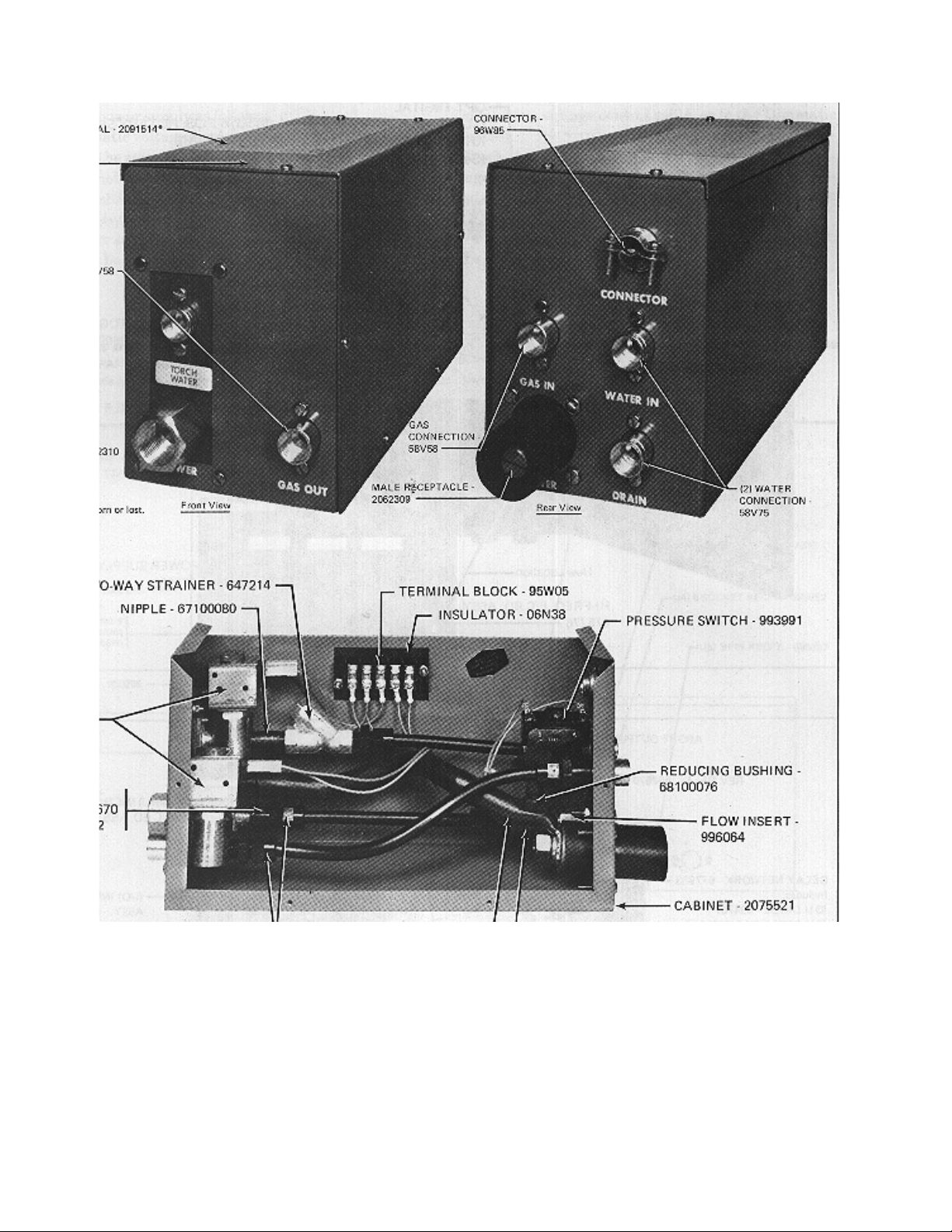
Fig. 11 - Optional Plumbing Box - P/N 677261
28
Page 29

D-31991 (C)
Fig. 12 - Schematic Diagram - Digipulse Automatic
29
Page 30

D-31992 (C)
Fig. 13 - Wiring Diagram - Digipulse Automatic, Sheet 1 of 2
30
Page 31

D-31992 (C)
Fig. 13A - Wiring Diagram - Digipulse Automatic, Sheet 2 of 2
31
Page 32

F-15-075-A 4/95 Printed in U.S.A.
 Loading...