

Page 1

INSTRUCTIONS for
F-15-240-A
April, 1997
DIGIMATIC II
FOUR SCHEDULE
MICROPROCESSOR
CONTROL
P/N 35635
FOR AUTOMATED MECHANIZED
MIG WELDING
SPECIFICATIONS
Input Power Required 7A., 115 volts, 50/60 Hz, 1 ph
Height 15.5-in. (394mm)
Depth 8-in. (200mm)
Width 13-in. (330mm)
Weight (approx.) 20-lbs. (9.1kg)
This manual provides complete instructions for the Digimatic II starting with Serial No. AF-I511029.
FEATURES/BENEFITS
n Presettable Wire Feed Speed (IPM) and Voltage
n Patented Microprocessor Controlled Closed Loop
F-15-240-A
n Four Presettable Welding Schedules...Unlike the
original single- schedule Digimatic II, this unit
allows you to preset up to four (4) completely
(VOLTS) ...Provides ability to easily and accurately preset the exact welding parameters desired, before the welding sequence begins!
System ...Provides most accurate means of maintaining wire feed speed (amperage) and welding
voltage. The microprocessor compensates for
deviations in ambient temperature, primary voltage fluctuation and changes in arc dynamics or
wire feed force conditions, to assure that preset
parameters are maintained.
These INSTRUCTIONS are for experienced operators. If you are not fully familiar with the principles of operation
and safe practices for electric welding equipment, we urge you to read our booklet, "Precautions and Safe
Practices for Arc Welding, Cutting and Gouging," Form 52-529. Do NOT permit untrained persons to install,
operate, or maintain this equipment. Do NOT attempt to install or operate this equipment until you have read and
fully understand these instructions, contact your supplier for further information. Be sure to read the SAFETY
PRECAUTIONS on page 3 and 4 before installing or operating this equipment.
different welding schedules that can save control
setup time and improve productivity. By preset-
ting four of your most common welding require-
ments, all you have to do is switch weldments and
select the appropriate schedule for that particular
job.
n Eight Presettable Conditions Per Schedule...In
sequence, including, PREFLOW, STRIKE, START,
WELD, CRATER, ANTI-STICK (Burnback), POST-
FLOW and WIRE RETRACT. Total weld condition
presettability means improved weld quality and
productivity.
Be sure this information reaches the operator.
You can get extra copies through your supplier.
Page 2

USER RESPONSIBILITY
This equipment will perform in conformity with the description thereof contained in this manual and accompanying
labels and/or inserts when installed, operated, maintained and repaired in accordance with the instructions provided. This equipment must be checked periodically. Defective equipment should not be used. Parts that are
broken, missing, worn, distorted or contaminated should be replaced immediately. Should such repair or replacement become necessary, the manufacturer recommends that a telephone or written request for service advice be
made to the Authorized Distributor from whom purchased.
This equipment or any of its parts should not be altered without the prior written approval of the manufacturer. The
user of this equipment shall have the sole responsibility for any malfunction which results from improper use, faulty
maintenance, damage, improper repair or alteration by anyone other than the manufacturer or a service facility
designated by the manufacturer.
TABLE OF CONTENTS
Specifications ........................................................................................................................................................ 1
Features/Benefits ............................................................................................................................................... 1/5
Safety Precautions ............................................................................................................................................. 3/4
I. INSTALLATION ................................................................................................................................................ 5
A. Required Equipment ..................................................................................................................................... 5
B. Optional Accessories .................................................................................................................................... 6
C. Mount/Connect Equipment ............................................................................................................................ 8
II. CONTROL FUNCTIONS .................................................................................................................................. 8
A. Front Panel Controls ..................................................................................................................................... 8
B. Inside Panel Controls .................................................................................................................................. 10
C. Additional Program Controls ....................................................................................................................... 12
III.PRESETTING WELDING SCHEDULES ........................................................................................................ 12
IV. WELDING SEQUENCE ................................................................................................................................ 14
V. TROUBLESHOOTING.................................................................................................................................... 15
VI. REPLACEMENT PARTS DATA .................................................................................................................... 19
Figure 1 - Interconnection Diagram .................................................................................................................. 7
Figure 2 - Front Panel Controls ........................................................................................................................ 8
Figure 3 - Inside Panel Controls ...................................................................................................................... 11
Figure 4 - MPU Dip Switch Location ................................................................................................................ 12
Figure 4-A - Typical Time Parameter Setup .................................................................................................... 12
Figure 5 - Typical Weld Condition Sequence Per Schedule ............................................................................ 15
Figure 6 - Sequential Troubleshooting Flow Diagram ...................................................................................... 18
Figure 7 - Control Assy. Replacement Parts/External ..................................................................................... 19
Figure 8, 9 - Control Assy. Replacement Parts/Internal ................................................................................... 20
Figure 10 - Plumbing Box Replacement Parts ................................................................................................. 21
Figure 11 - Control Schematic Diagram .......................................................................................................... 22
Figure 12, 13 - Control Wiring Diagrams .................................................................................................... 23/24
2
Page 3

SAFETY PRECAUTIONS
WARNING: These Safety Precautions are for
your protection. They summarize precautionary information from the references listed in
Additional Safety Information section. Before
performing any installation or operating procedures, be
sure to read and follow the safety precautions listed below
as well as all other manuals, material safety data sheets,
labels, etc. Failure to observe Safety Precautions can result
in injury or death.
PROTECT YOURSELF AND OTHERS
Some welding, cutting, and gouging
processes are noisy and require ear
protection. The arc, like the sun, emits
ultraviolet (UV) and other radiation and
can injure skin and eyes. Hot metal can cause burns.
Training in the proper use of the processes and equipment is essential to prevent accidents. Therefore:
1. Always wear safety glasses with side shields in any work
area, even if welding helmets, face shields, and goggles
are also required.
2. Use a face shield fitted with the correct filter and cover
plates to protect your eyes, face, neck, and ears from
sparks and rays of the arc when operating or observing
operations. Warn bystanders not to watch the arc and
not to expose themselves to the rays of the electric-arc
or hot metal.
3. Wear flameproof gauntlet type gloves, heavy long-sleeve
shirt, cuffless trousers, high-topped shoes, and a welding helmet or cap for hair protection, to protect against
arc rays and hot sparks or hot metal. A flameproof apron
may also be desirable as protection against radiated
heat and sparks.
4. Hot sparks or metal can lodge in rolled up sleeves,
trouser cuffs, or pockets. Sleeves and collars should be
kept buttoned, and open pockets eliminated from the
front of clothing
5. Protect other personnel from arc rays and hot sparks
with a suitable non-flammable partition or curtains.
6. Use goggles over safety glasses when chipping slag or
grinding. Chipped slag may be hot and can fly far.
Bystanders should also wear goggles over safety glasses.
FIRES AND EXPLOSIONS -- Heat from
flames and arcs can start fires. Hot slag
or sparks can also cause fires and explosions. Therefore:
1. Remove all combustible materials well away from the
work area or cover the materials with a protective nonflammable covering. Combustible materials include wood,
cloth, sawdust, liquid and gas fuels, solvents, paints and
coatings, paper, etc.
2. Hot sparks or hot metal can fall through cracks or
crevices in floors or wall openings and cause a hidden
smoldering fire or fires on the floor below. Make certain
that such openings are protected from hot sparks and
metal.“
3. Do not weld, cut or perform other hot work until the
workpiece has been completely cleaned so that there
are no substances on the workpiece which might produce flammable or toxic vapors. Do not do hot work on
closed containers. They may explode.
4. Have fire extinguishing equipment handy for instant use,
such as a garden hose, water pail, sand bucket, or
portable fire extinguisher. Be sure you are trained in its
use.
5. Do not use equipment beyond its ratings. For example,
overloaded welding cable can overheat and create a fire
hazard.
6. After completing operations, inspect the work area to
make certain there are no hot sparks or hot metal which
could cause a later fire. Use fire watchers when necessary.
7. For additional information, refer to NFPA Standard 51B,
"Fire Prevention in Use of Cutting and Welding Pro-
--
cesses", available from the National Fire Protection Association, Batterymarch Park, Quincy, MA 02269.
ELECTRICAL SHOCK -- Contact with live
electrical parts and ground can cause
severe injury or death. DO NOT use AC
welding current in damp areas, if movement is confined, or if there is danger of
falling.
1. Be sure the power source frame (chassis) is connected
to the ground system of the input power.
2. Connect the workpiece to a good electrical ground.
3. Connect the work cable to the workpiece. A poor or
missing connection can expose you or others to a fatal
shock.
4. Use well-maintained equipment. Replace worn or damaged cables.
5. Keep everything dry, including clothing, work area, cables,
torch/electrode holder, and power source.
6. Make sure that all parts of your body are insulated from
work and from ground.
7. Do not stand directly on metal or the earth while working
in tight quarters or a damp area; stand on dry boards or
an insulating platform and wear rubber-soled shoes.
8. Put on dry, hole-free gloves before turning on the power.
9. Turn off the power before removing your gloves.
10. Refer to ANSI/ASC Standard Z49.1 (listed on next page)
for specific grounding recommendations. Do not mistake
the work lead for a ground cable.
ELECTRIC AND MAGNETIC FIELDS —
May be dangerous. Electric current flowing through any conductor causes localized Electric and Magnetic Fields
(EMF). Welding and cutting current creates EMF around welding cables and
welding machines. Therefore:
1. Welders having pacemakers should consult their physician before welding. EMF may interfere with some pacemakers.
2. Exposure to EMF may have other health effects which are
unknown.
3. Welders should use the following procedures to minimize
exposure to EMF:
A. Route the electrode and work cables together. Secure
them with tape when possible.
B. Never coil the torch or work cable around your body.
C. Do not place your body between the torch and work
cables. Route cables on the same side of your body.
D. Connect the work cable to the workpiece as close as
possible to the area being welded.
E. Keep welding power source and cables as far away
from your body as possible.
3
11/95
Page 4

FUMES AND GASES -- Fumes and
gases, can cause discomfort or harm,
particularly in confined spaces. Do
not breathe fumes and gases. Shielding gases can cause asphyxiation.
Therefore:
1. Always provide adequate ventilation in the work area by
natural or mechanical means. Do not weld, cut, or gouge
on materials such as galvanized steel, stainless steel,
copper, zinc, lead, beryllium, or cadmium unless positive
mechanical ventilation is provided. Do not breathe fumes
from these materials.
2. Do not operate near degreasing and spraying operations. The heat or arc rays can react with chlorinated
hydrocarbon vapors to form phosgene, a highly toxic
gas, and other irritant gases.
3. If you develop momentary eye, nose, or throat irritation
while operating, this is an indication that ventilation is not
adequate. Stop work and take necessary steps to improve ventilation in the work area. Do not continue to
operate if physical discomfort persists.
4. Refer to ANSI/ASC Standard Z49.1 (see listing below)
for specific ventilation recommendations.
CYLINDER HANDLING -- Cylinders, if
mishandled, can rupture and violently
release gas. Sudden rupture of cylinder, valve, or relief device can injure or
kill. Therefore:
1. Use the proper gas for the process and use the proper
pressure reducing regulator designed to operate from
the compressed gas cylinder. Do not use adaptors.
Maintain hoses and fittings in good condition. Follow
manufacturer's operating instructions for mounting regulator to a compressed gas cylinder.
2. Always secure cylinders in an upright position by chain
or strap to suitable hand trucks, undercarriages, benches,
walls, post, or racks. Never secure cylinders to work
tables or fixtures where they may become part of an
electrical circuit.
3. When not in use, keep cylinder valves closed. Have
valve protection cap in place if regulator is not connected. Secure and move cylinders by using suitable
hand trucks. Avoid rough handling of cylinders.
4. Locate cylinders away from heat, sparks, and flames.
Never strike an arc on a cylinder.
5. For additional information, refer to CGA Standard P-1,
"Precautions for Safe Handling of Compressed Gases in
Cylinders", which is available from Compressed Gas
Association, 1235 Jefferson Davis Highway, Arlington,
VA 22202.
EQUIPMENT MAINTENANCE -- Faulty or improperly maintained equipment can cause
injury or death. Therefore:
perform any electrical work unless you are qualified to
perform such work.
2. Before performing any maintenance work inside a power
source, disconnect the power source from the incoming
electrical power.
3. Maintain cables, grounding wire, connections, power cord,
and power supply in safe working order. Do not operate
any equipment in faulty condition.
4. Do not abuse any equipment or accessories. Keep
equipment away from heat sources such as furnaces, wet
conditions such as water puddles, oil or grease, corrosive
atmospheres and inclement weather.
5. Keep all safety devices and cabinet covers in position and
in good repair.
6. Use equipment only for its intended purpose. Do not
modify it in any manner.
ADDITIONAL SAFETY INFORMATION -- For
more information on safe practices for electric arc welding and cutting equipment, ask
your supplier for a copy of "Precautions and
Safe Practices for Arc Welding, Cutting and
Gouging", Form 52-529.
The following publications, which are available from the
American Welding Society, 550 N.W. LeJuene Road, Miami,
FL 33126, are recommended to you:
1. ANSI/ASC Z49.1 - "Safety in Welding and Cutting"
2. AWS C5.1 - "Recommended Practices for Plasma Arc
Welding"
3. AWS C5.2 - "Recommended Practices for Plasma Arc
Cutting"
4. AWS C5.3 - "Recommended Practices for Air Carbon Arc
Gouging and Cutting"
5. AWS C5.5 - "Recommended Practices for Gas Tungsten
Arc Welding“
6. AWS C5.6 - "Recommended Practices for Gas Metal Arc
Welding"“
7. AWS SP - "Safe Practices" - Reprint, Welding Handbook.
8. ANSI/AWS F4.1, "Recommended Safe Practices for Welding and Cutting of Containers That Have Held Hazardous
Substances."
This symbol appearing throughout this manual
means Attention! Be Alert! Your safety is
involved.
The following definitions apply to DANGER, WARNING,
CAUTION found throughout this manual:
Used to call attention to immediate hazards which, if not avoided, will result in
immediate, serious personal injury or loss
of life.
Used to call attention to potential hazards which could result in personal injury
or loss of life.
1. Always have qualified personnel perform the installation, troubleshooting, and maintenance work. Do not
Used to call attention to hazards which
could result in minor personal injury.
4
Page 5

n Sure Start Interlock...To assure troublefree starts,
the Digimatic II has an interlock circuit which will
not allow wire feed to initiate unless the power
source contactor is closed and STRIKE voltage is
present.
n Presettable STRIKE Time...Assures safe consis-
tent starts. If for any reason the Strike Time is
exceeded (wire does not feed or misses the work)
the Digimatic II will automatically shut down and
flash the preset STRIKE TIME in the VOLTS display window.
n Arc Detector Circuit...Senses that both Welding
Voltage and Amperage are present to facilitate
transfer from Strike to Start condition parameters, and also provide a signal to initiate travel of
a carriage or fixture.
n Automatic Controlled Shutdown ...To assure
that all welding is performed only at the preset
parameters, Digimatic II will automatically shutdown in the rare event that either voltage or wire
feed speed cannot be maintained during the welding sequence.
n The Digimatic II will always sequence through a
controlled shutdown including dynamic motor
brake, anti-stick and postflow. Simultaneously,
the cause is indicated by a flashing VOLTS or IPM
display.
n Automatic Adaptive Anti-Stick or Manual Burn-
back Time Feature...The adaptive anti-stick feature automatically adjusts the same amount of
wire burnback, regardless of wire size, speed or
voltage. Or, you can manually preset a Burnback
Time to specifically suit a specialized application.
n Missweld Time...depending on the criticality of
the weld, this feature allows you to preset the
number of cycles of arc time that can reasonably
be missed during a welding condition and still
produce an acceptable weld. If more than the
allowable number of arc cycles are missed, the
unit will shutdown/abort and flash the preset
Missweld Time cycles in the IPM display window.
n Wire Retract Feature...Provides the ability to pre-
set a Wire Retract time which will assure that the
wire is well removed from the work area and not
subject to possible postweld bending due to contact with the workpiece or fixture.
n Independent Presettable Cold Wire Inch...To re-
duce down time for reloading welding wire, the
Digimatic II cold wire Inch speed can be independently adjusted (up to 999 ipm) without affecting
any of the other preset welding conditions.
n Circuit Protection...Resettable circuit breaker for
115 VAC, 50 or 60 HZ input power minimizes down
time and maintenance.
n Remote Control Capabilities...To provide easy
interfacing with fixtures, the Digimatic II incorporates remote Start/Stop and Wire Inch Capabilities which can be controlled by switches or relays at a central control panel.
n Single or Repeat Timed Weld Capabilities ...Be-
cause the Digimatic II incorporates a Repeat weld
timer, adjustable up to 999 cycles (16.5 seconds),
the Digimatic II offers more than conventional
continuous seam, or Single Times welding capabilities. It can also be preset for Repeat Timed
skip or stitch welding applications.
n Individual Digital Meters Provide Large 1/2-in.
Display of Voltage And Wire Feed Speed
IPM...After the arc is struck, the meters automatically transfer from preset to display of actual
VOLTS and IPM for each welding condition as the
Digimatic II sequences through the preset welding sequence.
n Arc Hours Readout...This unique feature pro-
vides a direct measure of productivity by accumulating and displaying, upon command, actual
welding Arc Hours.
n Unique Diagnostic Set-up/Test Circuit...Provides
the ability to totally test the Digimatic II electronics as well as run it through a complete timed
sequence of preset weld conditions without actually welding.
I. INSTALLATION
A. EQUIPMENT REQUIRED
1. Digimatic II Four-Schedule Control Assy. P/N
35635.
2. EH-10A Digital Welding Head (20-999 IPM). The
welding head is composed of three basic units; a wire
feed motor- tachometer unit, a gear reduction unit,
and the accessory support assembly. This control (4schedule) is only usable with a EH-10A Digital Welding Head, and either of two welding head (following)
are available for use. The wire sizes accommodated
are:
Hard .................................. .030 -1/8-in. (.8 - 3.2mm)
Soft ................................. .030 - 3/32-in. (.8 - 2.4mm)
Flux Core........................ .045 - 1/8-in. (1.2 - 3.2mm)
5
Page 6

a. Two Roll Drive EH-10A Head - P/N 600416.
This head provides wire feed speeds from 20 999 IPM using a 40:1 gear reduction ratio, and a
two-roll accessory support wire drive. The motortachometer power and control leads are provided
by a pair of 52 inch long cables connected to a 5pin amphenol. For further information refer to
booklet F-12-873.
a. R-5007 Argon Regulator/Flowmeter, P/N 998124.
b. Heavy Duty Gas Hose, P/N 19416 (12-1/2-ft.), or
P/N 19415 (25-ft.).
c. Gas Hose Coupling, P/N 11N17.
8. Water Cooling Requirements. When using a water
cooled torch (ST-16 and ST-21), the following are
required to supply and drain the cooling water:
b. Four Roll Drive E-10A Head - P/N 600417. This
head is the same as P/N 600416, except that it
incorporates a four- roll accessory support wire
drive assembly. For further information, refer to
booklets F-12-873 and F-12-821.
NOTE: If the motor direction is to be changed, inter-
change the blue and orange wires on T1-5 and
T1-6 positions on the terminal strip.
3. Feed Rolls. Select the proper feed roll, for the wire
size to be used, from the data provided in booklets F12-873 and F-12-821.
4. Constant Voltage Power Source. In order to use
the Digimatic II Control, it must be operated with
C.V. power sources designed with electronically
controlled arc voltage regulation, such as:
ESAB 452 cv, P/N 36000
ESAB 652 cvcc, P/N 36004
ESAB SVI-450i cvcc, P/N 31950
5. Welding Torch. A mechanized mig welding torch
having a rated capacity suitable for the welding application, such as:
a. ST-16 Water-Cooled Torch (for currents up to 600
amps) P/N 997498, or
b. ST-21M Water-Cooled Mechanized Torch (for cur-
rents up to 600 amps.) P/N 690509.
6. Power Source Control Cable (J1) Assembly.
Depending on the type of power source used (transformer- rectifier/SCR, or inverter), one of the following control cables is required.
a. 19-conductor control cable with 19-pin amphenol
plug each end order one of the following cables:
P/N 30686, 6-ft. long assembly.
P/N 30780, 30-ft. long assembly.
P/N 30781, 60-ft. long assembly.
7. Shielding Gas Regulation. A gas regulator/flowmeter and fitted hose are required to bring gas to the
torch, such as:
a. Water Hose, 12-1/2-foot, P/N 40V76or,
b. Water Hose, 25-foot, P/N 406196.
c. Water (In/Out) Adaptor (Connects hose to 1/4
NPT), P/N 11N16.
d. Water Hose Coupling, P/N 11N18.
B. OPTIONAL ACCESSORIES
1. Digital D.C. Ammeter Kit, P/N 679111. This kit
permits direct visual indication of welding current up
to 999 amps d.c., and is available as a field
installed option. The kit is designed for easy snapon/plug-in installation and consists of an LED Display P/C Board (P/N 675284), an Ammeter Control
P/C Board (P/N 675334), and assorted mounting
hardwarefor installation refer to booklet F-14-220.
2. Remote Control Cable (J3) Assembly; 25-ft. lg.,
P/N 30499. This cable assembly is used in conjunc-
tion with optional Interface Board Assembly, P/N
31482, and/or Abort/Output Board Assembly, P/N
600433. The combination provides remote wire inch-
ing, purge, start-stop, current detecting, and abort
output functions. See Fig. 9 for mounting location of
the board assemblies. The cable assembly is a 12conductor cable with a 14-pin amphenol plug on one
end and self-lead wire connections at the other end
for customer hook-up .
3. Plumbing Box Control Cable (J5) Assembly;
4 1/2-ft. lg. P/N 948273, or 25-ft. lg. P/N 678037.
This cable provides connections to energize solenoid valves for gas shielding and water cooling (if
connected) during the preflow, welding and postflow
cycles. It also provides as interlock to a pressure
switch in the water line which will shutdown the
control if the supply to a water-cooled torch is inadequate. This assembly is a 6-conductor cable with a
6-pin amphenol to self-lead wire connections.
4. Motor-Tachometer Extension Cable Assembly, P/N 996808. This assembly allows you to ex-
tend the welding head location using a 25-foot, 6
conductor cable (1-conductor not used) with a 5pin amphenol plug (which connects to the controls
J2 receptacle) and an 5-pin amphenol receptacle
(which connects to the EH-10s plug).
6
Page 7

DIGIMATIC II CONTROL
POWER SOURCE CONTROL
CABLE ASSYS. (19C., PIN)
30-FT. - 30780
60-FT. - 30781
To be used with Optional Interface Board
31482 and/or Abort Output Board 600433.
POWER
SOURCE
NOTES:
1. Both output welding cable leads (torch and work) must be a minimum size of No. 4/0 welding cable (nothing smaller), and both leads should
be kept as close to the same length as possible with neither lead exceeding 50-ft. in length. Also, both cables must be run next to each
other and tywrapped every couple of feet to minimize cable reactance.
2. If wire feed runs backwards, reverse motor direction as follows: in the control, disconnect the blue wire (RLY-7) from T1-5 and connect it to
T1-6; disconnect orange wire (RLY-9) from T1-6 and connect it to T1-5.
3. As shipped from the factory, the control is wired for air-cooled torch operation and this is provided by an insulated jumper splice connection
between pins J5-E and -F of the controls plumbing box receptacle J5. When water-cooled torch operation is to be used with the plumbing box,
the jumper splice (between J5-E and -F) must be disconnected because these pins will be connected across the water pressure switch in the
plumbing box. Also note that the pressure switch is factory-connected for normally-closed (NC) operation, and must be reconnected for
normally-open (NO) operation as shown above and in the schematic and detail wiring diagrams.
Figure 1 - Interconnection Diagram
7
Page 8

5. Gas and Water Solenoid Valves, P/N 636386.
Used to control flow of shielding gas and cooling
water.
6. Reel/Spindle Support, P/N 634288. This support
arm is utilized to mount either wire spools or coils. Will
mount to any fixture or to the OM-48 carriage when
the required support adaptor P/N 996498 is used.
7. Spindle Assy., P/N 948259. Mounts to Item 6 above
and is used for 12-in. diam. spools.
8. H.D. Spoke-Type Wire Reel, P/N 19V89. Mounts to
Item 6 above and is used for 65 lb coils.
A
A
7
6b
A
6a
A
6c
9. Spool Enclosure Kit, P/N 600240, covers and
protects 12-in. spools from dust and moisture.
10. WC-9 Coolant Circulator, P/N 33540 For use with
water cooled torches such as the ST-21. A fourgallon tank provides 1.0 gal/min. at 50 psi pump
capacity, using 115 volts, 50/60 Hz input.
11. Plumbing Box, P/N 677261 (for ESAB Water
Cooled Torches)
Plumbing Box, P/N 34749 (for other Water Cooled
Torches
The plumbing box assembly contains the solenoid
valves which provide shielding gas and cooling water
control. It is also equipped with a pressure switch in the
water line which (if connected) will shut down the
welding operation when the water supply is inadequate (see Fig. 1).
C. MOUNTING/CONNECTING THE EQUIP-
MENT
Since the operating controls are mounted on and
inside the Digimatic front panel, the box should be
located so that the meters and controls are within
easy reach of the operator. The control can be
mounted on a side-beam carriage or other vertical
surface by using the mounting holes provided.
For complete Interconnection Diagram of the
Digimatic II Control with all required and/or optional
related accessories, see Figure 1.
II. CONTROL FUNCTIONS
A. FRONT PANEL CONTROLS
For location of control features refer to Fig. 2.
1. Power Switch. Pulling-out the mushroom-style
red button of this switch turns power on in the control
as indicated by the illuminated display windows. To
turn power off, simply push-in the red button and the
display windows and control will deenergize.
A
1
A
8
Figure 2 - Front Panel Controls
A
2
A
4
NOTE: Immediately after the control is turned on,
a number (e.g.:3) will appear in the IPM read
and will only be displayed for 1-second.
This information identifies the current program (E-PROM) used in your control. When
a Program is changed, the new E-PROM will
automatically indicate a 2,3, etc. to identify
the program number being used. If a revision is made to an existing program, a decimal number .1,.2,.3, etc. indicating the
numerical revision will also appear in the
VOLTS readout window simultaneously.
2. Gas Purge/Reset Rocker. A momentary on switch,
this rocker provides a dual function when actuated.
a. Prior to starting the welding sequence, it
actuates the gas solenoid and lets you purge
the shielding gas line of the torch. At the same
time, the IPM and VOLTS windows will also display the preset times (in cycles) for gas preflow
and gas postflow respectively.
b. After starting the welding sequenceif an abort
shutdown condition occurs (indicated by flashing digital display), the Purge/Reset rocker
can be actuated and the control will automatically
reset for a new start.
8
A
3
A
5
Page 9

3. Schedule Select Switch. This four-position rotary
switch allows you to program and select Schedule
No. 1 and program (using the Condition Selector,
section II-B-1) a complete welding sequence for a
particular application. All of the remaining schedules
(No. 2, No. 3 or No. 4) can be programmed in the
same manner for each different welding application.
4. Inch Up-Down Rocker. This switch is used to cold
inch the wire, up or down, as a preset speed which
you have programmed on the inside panel (II-B-2-b).
IMPORTANT: Cold inching is only possible when the
weld Start-Stop rocker switch is in its
stop (or off) position.
5. Start-Stop Rocker. This two-position (no neutral)
switch initiates the welding sequence when placed in
its START position; and, depending on the type of
weldingSeam or Timed, terminates the welding
sequence in its STOP position as follows (for typical
setup procedures, refer to Section IV-F):
minute, in one-inch increments for each weld condition in the program sequence.
* With power turned ON, but not welding, the IPM
window will continuously read the Preset STRIKE
Condition wire speed setting. When the arc is struck,
the IPM window will then continuously read the Actual
welding wire speed as the weld conditions cycle thru
the welding sequence.
In addition to the above, and using the Condition and
Time selector controls on the inner panel (functionally
defined in II-B), this window can also display the following programmed times:
- PREFLOW. Shielding gas time from 0 to 999 cycles,
(16.5 sec.) in one cycle increments (60 cycles per
second).
- START TIME. Start time duration is factory preset at
6 cycles, and can be increased up to 999 cycles, in
one cycle increments.
a. Seam welding applications. The stop signal does
not immediately terminate the welding sequence.
It only terminates the weld condition. The sequence then transfers to the remaining conditions (crater fill, burnback, postflow/retract).
b. Single or Repeat T imed welding applications.
Although the stop signal is not normally used for
timed-welds, you may wish to prematurely terminate a burn-thru or unstable weld condition. When
the stop is used; all welding action (including
craterfill) will terminate, except burnback and
postflow/retract).
6. Digital Readout Windows. Three individual 3- digit
windows labeled AMPS (optional ammeter), IPM and
VOLTS are provided to display actual welding current, preset or actual welding parameters (wire feed
speed and welding voltage) and time parameters as
follows:
a. AMP Digital Readout. This window is normally
blank unless the optional Ammeter Kit is provided
to monitor actual welding current. When installed,
the window displays D.C. current (AMPS) in a
range from 0 - 999 amperes in one amp increments.
b. IPM Digital Readout. This window is primarily
used to display wire feed speed (IPM) for each of
the four welding conditions (Strike, Start, Weld,
and Crater) during a typical welding sequence.
Depending on the position of the inside condition
selector switch (functionally defined in II-B); the
IPM window displays actual and/or preset wire
feed speed in a range from 20 to 999 inches-per-
- WELD TIME. Weld condition duration for timedwelding (must be set to zero for Continuous-Seam
Welding), from 1 to 999 cycles, in one cycle
increments.
- CRATER TIME. Crater fill duration, from 1 to 999
cycles, in one cycle increments.
- MISSWELD TIME. Presets the number of cycles of
arc time that can reasonably be missed (from 1 up to
999 cycles) during the WELD condition and still produce an acceptable weld. If the number of missed
cycles match the preset cycles, the unit will abort.
Since the number of missed cycles to be preset
is based upon many variables, the required setting
for a given application obviously involves good judgment and technique. As an example, to set up a
critical 45 cycle spot weld, you might want to preset no
more than 5 cycles of missweld arc time. Be careful
not to make the missweld time too short, otherwise
nuisance aborts will occur. If this feature is not
desired, preset the time for zero cycles.
- INCH PRESET. Cold wire inch speed from 50 to 999
inches-per- minute, in one inch increments.
c. VOLTS Digital Readout. This window is primarily
used to display arc voltage (VOLTS) for each of the
four welding conditions (Strike, Start, Weld, and
Crater) during a typical welding sequence. Depending on the position of the inside Condition Selector
switch (functionally defined II-B); the VOLTS window displays actual and/or preset arc voltage range
from 12 to 50 vdc, in one-tenth (0.1) volt increments, for each weld condition in the program
sequence.
9
Page 10

* With the power turned ON, but not welding, the VOLTS
window will continuously read the Preset STRIKE
condition voltage setting. When the arc is struck, the
VOLTS window will then continuously read the Actual
welding voltage as the weld conditions cycle thru the
welding sequence.
In addition to the above, and using the inside "Condition"
and "Time" selector controls (functionally defined in IIB), this window can also display the following programmed
times:
Start, and after the Crater Conditions, none of
these lights will be on .
8. Reset Circuit Breaker. A seven (7) ampere circuit
breaker provides protection to the 115 volt control
circuit and the wire feed motor. If an overload occurs,
the breaker will trip and suspend all operation. To
restore service, simply depress the breaker button
on the front panel.
B. INSIDE PANEL CONTROLS
- POSTFLOW. Controls time for gas postflow after
the arc extinguishes from 0 to 999 cycles.
- STRIKE TIME. Preset time period allowed for the wire
to come down and hit the plate. If the wire does not
strike the plate within the allowed time period, the
Digimatic will automatically shutdown, and flash the
strike time in the VOLTS display window. Simultaneously, if optional abort output board is installed, it
also provides an abort output signal to stop carriage
or fixture travel. Time range is factory preset for a
minimum of 20 cycles and can be increased in one
cycle increments.
* The strike time setting is dependent upon the strike
IPM setting. The lower the speed, the longer the strike
time needs to be, otherwise nuisance shutdowns will
occur.
- BURNBACK TIME. Manually adjustable burnback time
period which when preset will override the automatic
adaptive anti-stick feature. This time period can be set
in one cycle increments. When set to zero , the
Automatic Adaptive Anti-Stick feature will be operational.
- REPEAT TIME (or Pause Time). Time period preset
between timed-welds from 1 to 999 cycles, in one
cycle increments.
- RETRACT TIME. At the end of the burnback sequence and during the postflow cycle, the wire feed
motor will reverse for automatic wire retract for a
preset time period. A setting of 5 to 10 cycles is
recommended to prevent excessive withdrawal of
the wire into the contact tip. If a normal stop is
desired, preset this time for zero cycles.
- ARC HOURS. Selectable display (record) of accumulative welding time in one tenth of an hour increments.
After 99.9 hours it will automatically return to zero.
7. Welding Condition (LED) Lights. These lights are
labeled START, WELD, and CRATER, and they energize individually as the welding program sequences
through each of these weld conditions. Prior to the
For location of internal control features, refer to Fig. 3
1. Condition Selector. This six-position rotary switch
is used to select two sets of parameters, Welding
and Timing, for each of the four available schedules:
a. Weld Parameters. The selectors primary func-
tion, when used with the appropriate Inc./Dec.
toggle, allows you to preset and display (see II-A6-b & c) the wire feed speed (IPM) and voltage
(VOLTS) weld parameters for its first-four positions labeled STRIKE, START, WELD, and
CRATER. The fifth position of this selector is
used for presetting the Missweld and Retract
Time. The sixth position of this selector, labeled
RUN, is the normal operating setting used after
the control is programmed and ready for use. The
IPM and VOLTS parameters, for each of the
following welding conditions, are preset using the
INC./DEC. toggle located directly.
- STRIKE. This condition sets the desired approach speed of the wire before striking the
workpiece, and the open-circuit voltage (on 452 cv
and 642 cvcc) needed to control the short-circuit
current for arc initiation.
- START. This condition can be used to set an appropriate wire speed and voltage parameter to create a
hot-start to help stabilize the arc (for its preset time)
prior to the weld cycle.
- WELD. This condition sets the desired wire speed
and voltage used during the actual weld cycle.
- CRATER. This condition allows you to set a higher or
lower weld speed and/or voltage (for a preset time
period), depending on the welding condition needed,
to regulate the weld termination size or craterfill
appearance at the end of the weld.
b. Time Parameters. The secondary function of this
selector is to setup the Time parameters located
within the charts adjacent to each of the weld
conditions. These times are preset by using the
Times/A.H.-Inch Selector (following).
10
Page 11

B
B
1
4
B
2
B
3a
B
3b
the data, simultaneously operate the INC/DEC
toggle switch directly below the function being set.
The cold-inch parameter will appear in the IPM
window, and the arc-hours time will be shown in
the VOLTS window.
3. Inc./Dec. Toggle Switches. A control toggle (two
position, momentary on ) is provided below the IPM
and VOLTS digital display windows. These two toggles
are used to preset the individual welding condition
and time-sequence parameters desired for the
welding operation, as follows:
a. IPM-TIME Increase/Decrease Control. This
toggle switch is used to set and/or vary wire feed
speed (IPM) for the required weld conditions , and
also the following; Preflow (time), Start Time,
Weld Time, Crater Time, Missweld Time and Inch
Preset (ipm). By setting and/or operating the appropriate Control Selectors (see B-1 and -2, above),
each parameter setting will be displayed in the
digital window directly above this toggle.
Figure 3 - Inside Panel Controls
2. Times/Arc Hours-Inch Preset Selector. This two
position, momentary on , toggle must be actuated in
order to preset or change the following parameters:
a. Time Functions. This position actuates the times-
parameters f o r t h e s e q u e n c e s s hown in the chart
beneath each digital display window. These sequences are preselected by positioning the Condition Selector to the pair of time-parameters to be
programmed from its Strike, Start, Weld, and Crater settings. To check or observe the time settings,
actuate the TIMES position; and to set or change
the settings, simultaneously operate the INC/DEC
toggle switch directly below the parameter (chart)
being setthe time setting in cycles will appear in
its digital display. The times-parameters which can
be programmed in each display window are shown
in Figure 3, and were previously described in Section II-A-6-b (IPM window) and Section II-A-6-c
(VOLTS window).
b. Arc Hours-Inch Preset Function. This switch
position operates in the same manner as the Times
function position; except that it only actuates the
programs to preset the Cold-Inch speed parameter
and to monitor or reset the accumulative Arc-Hours
(welding) time. These functions are preselected by
positioning the Condition Selector to its Run
setting. To check or monitor these parameters
actuate the A.H.- INCH position; and to set or zero
b. VOLTS-TIME Increase/Decrease Control. This
toggle switch is used to set and/or vary the arc
voltage (VOLTS) for the required weld conditions
, and also the following; Postflow (time), Strike
Time, Burnback Time, Repeat Time, Retract Time
and to zero (dec.) the Arc Hour accumulation. By
setting and/or operating the appropriate Control
Selector (see B-1 and -2 above), each parameter
setting will be displayed in the digital window
directly above this toggle.
4. TEST Toggle SwitchAMPS and VOLTS. As
the title implies, these two toggles simply provide a
convenient way of test-sequencing all of the program
parameters to either diagnose a problem or to demonstrate the control assembly without actually striking a welding arc. A complete set of actual weld
parameters must be preset for this test except for the
following: all voltage conditions and missweld time
parameters must be set to zerootherwise an abort
will occur.
To do this, place the two-position "Volts" toggle into
its TEST positionthe WELD position being the
location for normal operation. The Volts-Test position does two things: first, it safely disconnects the
actual contactor circuit in the power supply; and
second, it provides a 12-volt signal to simulate the arc
voltage required to sequence the welding cycle.
With this accomplished; open up the accessory support to release wire feed pressure, and place the
Start- Stop rocker on the front panel into its START
position, and the control will sequence thru the
programmedPreflow time and enter the Strike condition.
11
Page 12

Make sure that the Strike time is set long enough to
give you ample time to operate the Amp test toggle
a setting of 200 cycles is recommended for Strike
time.
During the Strike condition; you must actuate the
momentary "Amps" toggle to its TEST position, to
simulate closure of the arc/current detection circuitry
that verifies the arc has initiated. This action automatically allows you to enter the timed Start condition,
and the subsequent Weld, Crater, etc., conditions to
evaluate and/or demonstrate the welding sequence.
NOTE: The momentary WELD position of the Amps
toggle has no significance in the Test procedures. The normal spring-return center position, and/or its toggled Weld position essentially perform the same function.
C. ADDITIONAL PROGRAM CONTROLS
A. Pull the Power button out to energize the control, and
then place the Schedule Select switch to position No.
1. The control is now ready to accept Schedule No.
1 welding sequence program as described in steps
B thru I following:
B. Unlock the front panel door of the control cabinet to
gain access to the inside panel controls.
C. Make sure the Test-Volts and Amps toggle switches
are in the WELD position.
D. Place the rotary Condition selector switch to the
Strike position, and program each of the following
(see Sect. II-A-6-b, -c and II-B-1,-2):
1. Set the STRIKE wire feed speed (IPM) by operating the INC./DEC. toggle directly below the
IPM digital display, and the desired setting will
appear in its window.
The MPU (microprocessor) board incorporates an
integral 4-rocker/position dip switch (see Fig. 4)
that is primarily used for internal program functions. Switch positions No. 1, No. 2, No. 3 and No. 4
are factory-set in the open (or off) position and
must never be changed.
ROCKER DIP SWITCH
Figure 4 - MPU Dip Switch Location
2. Set the STRIKE open-circuit voltage requirement (VOLTS) by operating the INC./DEC. toggle
directly below the VOLTS digital display, and
the desired setting will appear in its window.
3. Leave the rotary selector switch in the STRIKE
position to set the PREFLOW and POSTFLOW
Time parameters (as shown in Fig. 4A). Actuate
the Times/A.H.-INCH toggle switch to its TIMES
(Cycle) position, and observe that the existing
numbers shown in the IPM and VOLTS windows
will changethe new parameters being the pair
of time functions in the chart(s) adjacent to the
selected condition (in this case, the pre- and
postflow data).
III. PRESETTING THE WELD SCHEDULE(S)
Remember, the front panel SCHEDULE SELECT
switch allows you to preset a complete and different
welding program for each of the four (4) available
schedules. To preset a typical schedule, do the
following.
Figure 4-A - Typical Time Parameter Set Up
To reset or change these Time parameters (see
Fig. 4A); actuate and hold the TIMES toggle position, while simultaneously operating the appropriate INC./DEC. toggle switch below each of the
12
Page 13

time parameters being set. The preset time intervals will be displayed in their respective IPM and
VOLTS digital windows.
E. Reposition the rotary Condition Selector switch to the
Start position, and program the following:
1. Set the START wire feed speed (IPM) and arc
voltage (VOLTS) parameters using the procedures outlined in III-D-1 and -2.
2. Leave the rotary selector in the START position to
set the START TIME and STRIKE TIME parameters and use the procedure outline in III-D-3.
F. Reposition the rotary Condition Selector switch to the
Weld position, and program the following:
1. Set the WELD wire feed speed (IPM) and arc
voltage (VOLTS) parameters using the procedures outlines in III-D-1, and -2.
2. Leave the rotary selector in the WELD position to
set the WELD TIME and BURNBACK TIME parameters and use the procedures outlined in III-D3, and also the following:
a. WELD TIME setting requirements for:
(1) Continuous Seam Weldingset time to
zero .
(2) Single Time Weld without carriage travel
(customer must deenergize the arc detection output signal)set time from 1 up
to 999 cycles.
(3) Single Time Weld with carriage travel (the
Arc Detector Circuit provides a signal to
initiate travel of a carriage, or fixture)set
time from 1 up to 999 cycles.
(4) Repeat Timed Weld (same as 3) except
that the elapsed time between welds is
preset in the REPEAT TIME parameters.
b. BURNBACK TIME setting requirements:
(1) If automatic adaptive anti-stick is desired
set time to zero.
(2) If manual burnback (anti-stick) is needed
set time required from 1 cycle on up.
G. Reposition the rotary Condition Selector switch to the
Crater position, and program the following:
1. Set the CRATER wire feed speed (IPM) and arc
voltage (VOLTS) parameters using procedures outlined in III-D-1 and -2.
2. Leave the rotary selector switch in the CRATER
position to set the CRATER TIME and REPEAT
TIME parameters and use the procedure outlined
in III-D-3.
* If the Weld Crater conditions are both Timed;
simply preset the appropriate time desired for each
condition - .1 up to 99.9 seconds for Weld, and .1
up to 99.6 seconds for Crater.
If Crater Fill is desired; enter from 1 to 999 cycle in the
Crater Time parameter. If Crater Fill is not desired;
simply enter zero in the Crater Time parameter, and
this sequence will be skipped after the STOP switch
terminates the Weld condition sequence.
** Repeat Timeif repeat timed welds are not used,
set this time to zero . If repeat welds are desired,
the cycles set will control the elapsed time between the Timed weld parameters.
H. Reposition the rotary Condition Selector switch to the
blank position, and program the following:
1. Set the MISSWELD TIME* and RETRACT TIME
parameters using the procedures outlined in III-D-
3. *The Missweld cycle only monitors the WELD
Condition. If not desired, set Missweld Time to
zero .
I. Reposition the rotary Condition Selector switch to the
RUN position for the following operations:
1. This is the normal operating setting used when the
control is fully programmed and ready-for-use.
As mentioned earlier in the Note following Section
II-B-2-b, the control is preset at the factory to
provide the optimum starting characteristic for most
welding conditions. However, due to factors such
as differences between various power sources
welding technique, shielding gas, power source
slope and/or response, you may have to readjust
the factory-set starting characteristics to provide the best arc starts possible. To do this, it is
necessary to readjust the factory-set condition to
provide a hot start characteristic in which the initial
starting voltage (open-circuit voltage) will be slightly
higher than actual welding voltage (arc voltage)
and speed which initially is somewhat lower than
the selected wire feed speed desired.
To set-up the control to provide this, do the following:
a. Program the welding condition you need in the
IPM (wire feed speed) and VOLTS (arc voltage)
windows, and fine-tune these parameters until
you have the welding arc desired - Do not at this
point concern yourself with the arc starts , this
follows.
b. If after the welding condition is fine-tuned you
find that the arc starts are unsatisfactory,
proceed as follows:
13
Page 14

(1) During an actual weld, depress and hold the
Arc Hours/Inch Preset toggle position
and observe the numbers displayed in the
IPM and VOLTS windows.
(2) For proper starts, the number in the
IPM window should be in the range from
105 to 115. If it is not, adjust the Inc/Dec
toggle (below the IPM window) until the
displayed number reads 110.
(3) Similarly, the number in the VOLTS win-
dow should be in the range of 90 to 100.
Again, if it is not, adjust the Inc/Dec toggle
(below the VOLTS window) until the displayed number reads 95.
(4) These adjustments to the control should
now provide good arc starts to a viable
welding condition.
(5) A good rule-of-thumb to follow whenever
you set up a new welding condition and
you experience unstable starts, is to simply check the start characteristic numbers (while welding) to make sure they
are within the ranges described in the
preceding steps.
2. Set the cold wire INCH wire feed speed and monitor
or reset (zero) the ARC HOURS by actuating Arc
Hours-Inch Preset toggle switch position, while operating the appropriate INC./DEC. toggle below
their respective charts. The preset cold-inch wire
feed speed, and accumulated arc hour usage will be
displayed in the appropriate IPM/VOLTS digital
windows.
NOTE: Upon completion of Schedule No. 1, if more
than one schedule is desired, place the
SCHEDULE SELECT switch to each of the
remaining positions (No. 2, No. 3 and No. 4) and
preset a different welding sequence program in
the same manner as Schedule No. 1.
IV. WELDING SEQUENCE
After the desired parameters have been weld-tested
and satisfactory results achieved, the preset condition can be lock-in by securing the front panel door
to the cabinet with a lock. None of the welding
parameters can be altered once the cover is closed.
To operate the preset welding schedule do the
following (a typical welding sequence is shown in
Fig. 5):
A. Pull the Power switch button out to energize the
control. (For one second, the IPM and VOLTS will
display an identification program number for the MPU
printed circuit board in your control.)
B. Operate the GAS PURGE switch to purge the
shielding gas line of the torch.
C. Place the SCHEDULE SELECT switch to the desired
schedule No. 1, No. 2, No, 3, or No. 4.
D. Operate the cold wire UP/DOWN INCH switch to
position the wire above the workpiece.
E. You are now ready to weld in the selected schedule.
Place the Start-Stop switch in its START position,
and the control will automatically sequence thru
Preflow, Strike, Start (also initiates arc detector carriage drive signal), and into the Weld condition
programmed.
F. To stop welding, proceed as follows:
1. For continuous seamwelds, simply operate the
STOP switch (or a remotely actuated stop
button or micro switch), and all welding will
cease except Crater-Fill, Burnback, Postflow and
Retract.
2. For single "Timed" weld setup, the control will
automatically provide an orderly sequenced shut
down; however, in order to start another weld, you
must press the Stop switch (panel or remote)
and then reoperate the Start position to reinitiate
the preset sequence.
3. For repeat "Timed" weld setups, the control will
automatically continue to cycle through its preset weld on and weld off sequence, until the
Digimatics Stop (or remote stop device) is operated.
4. The control can, or will, also shutdown as a result
of the following:
a. If preset Strike Time or Missweld Time is
exceeded, and /or preset wire feed speed or
arc voltage parameters cannot be maintained,
the Digimatic will shutdown and simultaneously indicate the cause by flashing a digital
display in the IPM or VOLTS window.
(1) If the Strike Time parameter was exceeded,
its preset time-interval will flash in the
VOLTS WINDOWand you may have to
preset a little more time.
(2) If the Missweld time cycles was exceeded,
its preset time will flash in the IPM window
and the unit will abort/shutdown make
sure that all parameters accurately reflect
the welding application.
14
Page 15

WELD MODE STARTS
WELD TIMER STARTS IF PROGRAMMED
WELD PARAMETERS ARE MAINTAINED
MISSWELD TIME STARTS
MONITORING
ARC DETECTOR
START TIMER BEGINS
START MODE INITIATED
PREFLOW TIMES OUT
CONTACTOR ON
MOTOR STARTS AT
STRIKE IPM SETTING
STRIKE TIMER STARTS
TIMIMG
START SW OPERATED
PREFLOW STARTS
PREFLOW
PURGE COLD INCH PRESET
MOTOR STOPS REVERSING
WIRE RETRACT ENDS
POSTFLOW TIMER STARTS
START TIMER
TIMES OUT
WIRE HITS
WORKPIECE
STRIKE START
CRATER TIME STARTS
CRATER PARAMETERS
MAINTAINED
STOP SW OPERATED
WELD TIMER TIMES
OUT IF SCHEDULED
MISSWELD TIME
ENDS
TIME
WELD
MISSWELD
AUTOMATIC OR
MANUAL ANTI-STICK
TIMER STARTS
DYNAMIC BRAKE
APPLIED
CRATER TIMER
TIMES OUT
ANTI-STICK TIMER TIMES OUT
CONTACTOR DROPS OUT
CRATER
POSTFLOW TIMES OUT
ANTI-STICK
Figure 5 - Typical Welding Conditions Sequence Per Schedule
REPEAT TIMER
STARTS IF
SET.
IF NOT WELD
CYCLE IS OVER
MOTOR
REVERSES
FOR WIRE
RETRACT
POSTFLOW
RETRACT
REPEAT
TIMER
STOPS &
NEW
WELD
BEGINS
REPEAT
(3) If the wire feed speed (IPM) and/or arc
voltage (VOLTS) parameters cannot be
maintained in any of the welding conditions (Strike, Start, Weld, or Crater), the
flashing display will only signal the original
preset Strike parameter(s).
b. In order to restart an abort shutdown, simply
depress the Gas Purge/Reset rocker switch
to clear the abort, and then repress the Start
rocker switch to start a new weld.
V. TROUBLESHOOTING
Listed below are a number of trouble symptoms,
each followed by the checks or action suggested to
determine the cause. Listing of checks and/or actions is in most probable order, but is not necessarily 100% exhaustive. In addition to the following
troubleshooting symptoms/checks, we have also
provided a Sequential Troubleshooting Flow Diagram (Fig. 6) which can be very useful in your
diagnosis.
Always follow this general rule: Do not replace a
printed circuit (PC) board until you have made all
the preceding checks. Always put the Power switch
in off position before removing or installing a PC
board. Take great care not to grasp or pull on
components when removing a PC board. If a printed
circuit (PC) board is determined to be the problem,
check with your ESAB supplier for a trade-in on a
new PC board. Supply the distributor with the part
number of the PC board as well as the serial number
of the wire feeder. Do not attempt to repair the PC
board yourself. Warranty on a PC board will be null
and void if repaired by customer or an unauthorized
repair shop.
A. General
1. Check interconnection between digimatic control and
power supply. Make sure that the contactor and
voltage control switches are placed in the Remote
position.
2. Energize the power supply and the control.
3. Immediately after the control is turned on , a number
(e.g.:3) will appear in the IPM readout window and will
only be displayed for 1-second. This number identifies the current program (E-Proms) used in your
control. When a Program is changed, the new EProms will automatically identify the new program
number being used. If a revision is made to an
existing program a decimal number .1,.2,.3,etc. indicating the numerical revision will also appear in the
VOLTS readout window simultaneously.
4. After the one (1) second delay; the preset Weld
parameters, corresponding to the position of the
Condition selector switch, will be displayed in the
IPM/ VOLTS windows. With the switch in its normal
Run position the STRIKE parameters will initially
be displayed.
5. It is also important to set the STRIKE time long
enough to provide adequate time for the current
detector to energize before the Strike timer times
out. If the Strike timer times out the unit will abort and
the preset Strike time parameters will flash in the
VOLTS window.
15
Page 16

6. If the control is not functioning properly (or as described above); for example, the numbers that appear in one or both of the display windows are
meaningless (all zeros, eights, decimals, etc.), or
are completely incorrect in relation to your settings,
- the memory must be cleared. This condition might
occur after a bad lightning storm, extremely bad
power line surges, etc. To clear the memory, do the
following:
a. Turn off the units 110-volt Power switch.
b. Using one hand, hold both of the Inc./Dec. toggle
switches in their INC position while reapplying 110volt power with the other hand.
c. Almost immediately after the Power has been
turned On, release the Inc./Dec. toggle switches
to the neutral (spring-return center) position and
each of the windows should display one zero,
indicating a successful reset or clearing has taken
place.
7. You can now enter the desired information as
described in this booklet.
B. No preset numbers, or meaningless numbers,
appear in display windows.
carriage drive(s), drill motor, hot plates, etc.) also
derive their 115-volt power from the same power
supply as the Digimatic control. Do NOT connect
auxiliary equipment to the 115-volt duplex receptacle
on the power supply. If problem still exists, call for
factory assistance.
C. Motor does not run.
1. Check to make sure all required (and/or optional)
accessories are correctly assembled as described in
Section I.
2. Make sure that plug P2 is securely connected to
receptacle P2 on the I/O Board, and then release the
clapper arm (pressure roll) on the Accessory Support
Assembly.
a. Operate the Start Switch (arc voltage of 10 volts or
more must be present) and the motor shaft/feed
roll should turn. If motor doesnt run, release start
switch and;
b. Operate the INCH switch. If the motor inches , but
will not operate from the start switch, check the
start switch circuit componentsswitch, plug,
receptacle, etc.
1. Make sure the LED Display board harness/plug
is plugged into the P5 receptacle on the MPU board.
2. Check that 110 vac is available across terminals T11 and T1-3, if present;
3. Check for (+) 5 volts between terminals T1-12 and
T1-10; if voltage is present, replace the MPU board.
If voltage is not present, check the voltage
regulator (VR). The voltage regulator is located on
the bottom of the control box.
4. Check the input and output voltage of the regulator
VR as follows:
The input should be approx. 11 volts, as measured
across capacitor C4 (between T1-10 and VR-1)
located on the VR socket. If voltage is not present
check the output of transformer CTR-1. It should read
10 volts AC from the center tap (Grn/Yel) to both of
the green windings taps. If CTR-1 good, but the input
to VR is still not present, check plug P3 per the
schematic diagram. If no opens or shorts are found
and input is still missing (to VR)replace I/O board.
If input to VR is present, but output is missing
replace VR. If numbers still do not appear in windowsreplace I/O and/or MPU boards.
c. If motor will not turn using either of the above
switches, replace the J governor board. If motor
still refuses to run, replace the I/O and MPU
boards respectively.
D. Motor runs backwards.
1. Reverse blue and orange wires on T1-5 and T1-6.
E. Motor runs, but not at right speed.
1. Check tachometer assembly mounted on the end of
EH-10 wire feed motor.
2. Make sure the tach disc is securely fastened to the
motor shaft and that the strobe markings are not
scratched. Check that the disc is properly centered in
the strobe pickup on the p.c. board.
3. If all items in step 2 are in order, and motor speed is
still incorrect, replaced MPU board.
F. Arc VOLTS display reads zero after TS is oper-
ated.
1. Check that the 5-pin plug is securely connected to the
P3 receptacle on the MPU board.
5. If all microprocessor memory is lost, it may be due to
low (sagging) line voltage or excessive line voltage
drops. This may occur if auxiliary equipment (such as
2. If no reading is displayed, check for arc voltage
feedback between terminals T1-18 and T1-19 (test
points TP1 and TP2, respectively, on I/O board). This
16
Page 17

voltage signal should correspond to that shown on
the power supply voltmeter.
3. If voltage still reads zero, but power supply indicates
a potential, trace the voltage pickup wiring from
the power supply to digimatic. If wiring is correct
and problem persist, proceed to step 4.
4. Disconnect the P3 plug from its MPU board socket
and, using a meter check for +/-12 volt power supply
output between plug pins P3-1 and P3-2 (for +12 v.),
and between plug pins P3-4 and P3-2 (for -12
v.) respectively. If voltage is present, replace the
MPU board.
G. Control Shut Down - either present VOLTS or IPM
displays will flash. The control will flash the
parameter, VOLTS or IPM, that cannot be maintained.
If this condition occurs, the respective servos need
to be checked and, if necessary, readjusted as
follows:
NOTE: The servo checking/setting procedure for the
Digimatic II control contained herein is different
from all previous Digimatic controls. Therefore, you do not need to adjust the voltage
servo trimpot or speed servo trimpot on the I/
O p.c. board - these trimpots are factory-set
and sealed, and should never be adjusted (as
was required of older Digimatics).
1. This symptom can occur as a result of the either or
all of the following; the Speed and Voltage servo
adjustments are incorrect and the conditions "set "
may not be maintainable. To check and, if necessary,
readjust the servos - proceed as follows.
Open the pressure roll clapper (so as not to feed wire),
toggle-down the Arc Hrs/Inch Preset switch position,
and either place the weld Start/Stop switch in START
position or toggle down the INCH switch. Check the
number in the IPM window - it may appear unsteady
but readable and should be about 110.
If it is higher or lower, use the Inc/Dec toggle (below
the IPM window) to adjust the number to 110 - while
"holding" the A.H.\Inch Preset as mentioned above
and while the wire feed motor is running.
If the speed servo cannot be adjusted at all, the
problem may be in the J-Governor, and/or I/O, and/or
MPU p.c. boards which must be replaced as required.
4. If a Voltage abort had occurred (VOLTS window
flashing), check and/or adjust the voltage servo as
follows:
This is a two-man operation. Set a welding condition
which closely corresponds to your welding application
and the proper speed (ipm) for a given wire size, and
then place the Weld switch in Start position and strike
a welding arc. While welding, toggle-down the Arc
Hrs./Inch Preset switch position and read the
number displayed in the VOLTS window, it may
appear unsteady but readable and should be 95.
If the number is not in the 90-100 range, use the Inc./
Dec toggle (below the VOLTS window) to adjust the
number to 95 - while holding the toggle position
mentioned above and while welding.
5. If the voltage servo cannot be adjusted, check
for proper operation of the power supply as follows:
NOTE: Prior to checking the servos, make sure the
control is connected to a suitable power source
in order to obtain the necessary o.c.v. (open
circuit voltage); otherwise, the motor will not
run.
2. The Speed and Voltage servos in this control
are simultaneously checked and displayed by depressing and holding the Arc Hrs./Inch Preset switch
(on inside panel) in its "down" position during an
actual weld and the wire feed motor running. The
speed servo number is displayed in the left (IPM)
window and should be about 110, and the right
(VOLTS) window will display the voltage servo number. This number will between 90 and 100* for the
actual welding condition.
* Voltage servo setting below 95 will normally provide
hot arc starts; whereas, setting over 100 will not.
3. If a Speed abort had occurred (IPM window flashing),
check and/or adjust the speed servo as follows:
a. Set the Digimatic voltage display to zero (this
setting will override the servo).
b. Place the Panel/Remote switch on the power sup-
ply in PANEL position.
c. Make a weld by controlling the arc voltage directly
from the power supply potentiometer.
d. If a weld can be made with good control over power
supply voltage; a problem exists either in the interconnecting voltage control cable, or in the Digimatic
control.
e. Check the control wires in the interconnecting
voltage control cable for continuity between the
appropriate terminals in the power supply and
Digimatic using the schematic diagrams.
f. If continuity is correct, replace the I/O board and/ or
the MPU board.
17
Page 18

IMPORTANT: In addition to the Welding Condition Sequence Diagram (Figure 5) and the Trouble Symptom/checks described
in Section V, the Sequential Troubleshooting Flow Diagram (Figure 6) can be very useful in diagnosing your problem.
Before using the Flow Diagram, make sure the Digimatic Control is connected to a suitable ESAB power source designed for
electronically controlled arc voltage regulation (see Section 1-A-4). The power supply much be setup for "remote" operation, and
the control preset and energized to provide the desired welding condition parameters.
If you wish to troubleshoot the Digimatic Control without using a power source, two TEST toggle switches labeled "Amps" and
"Volts", on the inside control panel provide a convenient way to "test-sequence" all of the welding condition parameters without
actually striking an arc. To do this, the control must be connected to an external 120 VAC power source (by customer),
preset all "arc voltage" condition parameters to zero (0) cycles, and preset the "Strike-Time" parameter to at least 150
cycles. The extended strike-time period is necessary to allow enough time to manually simulate an arc detection signal by
momentarily actuating the "Amp" toggle TEST position. Now, place the "Volts" toggle to its TEST position, and release the
clapper on the accessory support to remove wire feed pressure. With this accomplished, follow the Flow Diagram instruction
sequence until the weld condition is into the Strike-Time sequence. During this time period you must actuate the "Amps-Test"
toggle (to simulate arc detection), otherwise the strike-time will time out and the control will abort as shown in the diagram. If
done correctly, the unit will automatically continue through the remaining welding sequences.
(START)
1. START Sw. or Harness is Defective.
2. Defective MPU
3. Opt. Water Pressure Sw. is not closed.
No
Operate
Start Sw.
Yes
Are
Pre/Post
Flow Numbers
Displayed
Yes
Has
Pre-Flow
Timed
Out
Yes
1. P. S. Provides Strike Voltage.
2. Wire Feeds (n) Preset Strike IPM. n
3. Strike Timing Starts.
4. Strike Parameters Are Displayed.
No
1. Post-Flow Starts.
2. Pre-/Post-Flow Parameters Displayed.
3. Motor Starts Retract. C
A
1. Crater Parameters Are Displayed.
2. Crater Timing Starts.
3. Opt. Carriage Travel Stop.
Is
Crater time
Up
Ú
Is
Post-/
Flow (Retract)
Time Up
No
Yes
No
Continue
Crater
Cycle
Retract
Time
Yes
Is
Up
No
Wire
Retract
Has
Strike Timer
Timed
Out
Yes
Unit Will Abort
And Strike Time
Will Flash
No
Has
Missweld
Timed
Out
Yes
Unit Will Abort
And Missweld Time
Will Flash in IPM
No
1. Curr. Detector Signal Picks-up l
2. Start Parameters Are Displayed
3. Start Timing Begins
4. Carriage Drive Signal Provided.
1.Weld Parameter Are Displayed
2. Weld Cycle Start For:
Timed Weld
Weld time
No
Has
Wire Hit
Workpiece
Yes
Is
Start time
Up
Yes
Continuous Seam
Is
Up
No
Yes
Weld in
Progress
Stop Sw.
Operated
No
Yes
No
Is
Is
Repeat
Time Set
*
Yes
Is
Repeat Time
Up
NOTES
Motor will not feed unless an arc voltage of at least 10 volts is fed back
into the control; therefore, if power source does not operate, the motor
will not feed.
Check Curr. Detector p.c. board input and output.
If motor does not retract, but the manual inch up/down can be
performed, check and/or replace the MPU or I/O p.c. boards
respectively.
Repeat time can only be used in Timed-weld applications.
Return To Idle
No
State, Strike
Parameters are
Displayed
No
Continue
Timing
A
Figure 6 - Sequential Troubleshooting Flow Diagram
18
Page 19
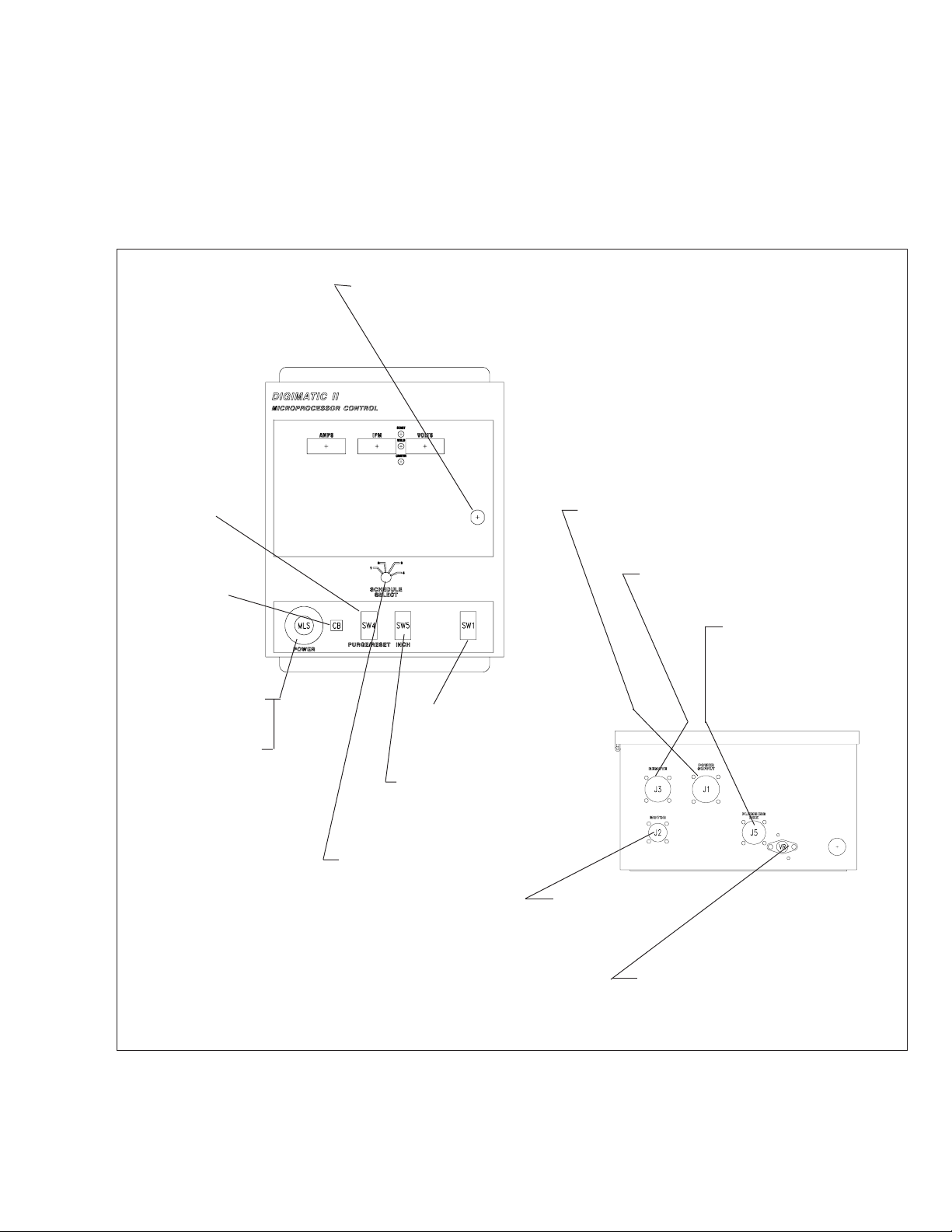
VI. REPLACEMENT PARTS DATA
1. All replacement parts are keyed on the illustrations which follow. Order replacement parts by part number and part
name, as shown on illustrations. DO NOT ORDER BY PART NUMBER ALONE.
2. Always state the series or serial number of the machine on which the parts are to be used. The serial number is
stamped on the unit nameplate.
CABINET LOCK - 950416
(SW4/PRS)
ROCKER
SW. - 950295
(CB) CIRCUIT
BKR. - 950874
(MLS)
OPERATOR - 950915
CONTACT - 950916
BUTTON - 950917
(SW1/SSS)
ROCKER
SW. - 2062270
(SW5/UDIS)
ROCKER
SW. - 2062363
(SSW)4-POS. ROTARY
SW.- 678915
KNOB - 950282
(D3, D4) DIODE - 950504
(on SSW)
(J1) 19-PIN RECPT. - 950762
(C20) CAPACITOR - 950265
(J3) 14-SOCKET RECPT. 636665
(J5) 6-SOCKET RECPT. 993952
(J2) 5-SOCKET
RECPT. - 996514
(VR) VOLTAGE REGULATOR - 950159
TRANSISTOR SOCKET - 950158
(C4) CAPACITOR - 995544
Figure 7 - Digimatic II Control Assembly, P/N 35635
19
Page 20

OPT, DIGITAL D,C, AMMETER
KIT - 679111
(SW9/V TST) TOGGLE SW. - 950229
(MSS) 6-POS. ROTARY SW. - 679914
KNOB - 950282
WASHER - 950291
DISPLAY P/C BD. ASSY. - 675269
(SW 10/A TST)
(SW8/AH)
(SW7/SID)
(SW6/VID)
TOGGLE SWS. 950087
}
(R1) RESISTOR - 17240003
(REVRLY) REV. RELAY - 951089
(BR) BRIDGE - 996556
(CTR3) CONTROL
TRANSFORMER 994303
(FNI) FILTER NETWORK - 996918
Includes:
(C1, C2) CAPACITOR - 672348
(C3) CAPACITOR -993716
TIE POINT - 94W84
Figure 8 - Digimatic II - Inside Control Panel
(T1) TERMINAL BOARD - 995103
A/O
OPTIONAL ABORT/OUTPUT BOARD - 600433
OPTIONAL I/F BOARD - 31482
(CTR 2) CONTROL TRANS. - 994303 (TOP.)
(CTR 1) CONTROL TRANS. - 950088 (BOT.)
(I/O) INPUT/OUTPUT P.C. BD.
ASSY. - 674956
(MPU) MICROPROCESSOR
P.C. BD. ASSY. - 18139
J-GOV. P.C. BD. ASSY. - 994236
CURR. DETECT. P.C. BD.
ASSY. - 675280
(2) P.C. BD. RECEPTACLES 636608
Figure 9 - Digimatic II - Inner Cabinet Components
20
Page 21

WARNING DECAL - 2091514*
COVER - 996065
GAS CONNECTION - 58V58
INSULATING BLOCK
ASSY. 994344
Includes:
INS BLOCK - 994149
WATER CONNECTION 58V75
TORCH POWER
ADAPTOR - 634090
(2) JAM NUT 5/8" 18,
63340230
FEMALE CONNECTOR - 2062310
CONNECTOR - 96W85
25-FT., 4-COND. CABLE - 996380
25-FT., 3-COND. CABLE - 73635891
*Replace decal if excessively worn or lost.
SUPPLIED
Front View
GAS
CONNECTION
58V58
MALE RECEPTACLE
2062309
CONNECTOR 96W85
Rear View
(2) WATER
CONNECTION
58V75
TWO-WAY STRAINER - 647214
GSV, WSV
SOLENOID
VALVE - 636386
(3) FEMALE
CONNECTOR - 636670
(3) INSERT - 636402
(3) MALE CONNECTOR - 636669
(3) INSERT - 636402
NIPPLE - 67100080
TERMINAL BLOCK - 95W05
INSULATOR - 06N38
PIPE TEE - 68161103
POWER CABLE - 996063
PRESSURE SWITCH - 993991
REDUCING BUSHING
68100076
FLOW INSERT
996064
CABINET - 2075521
Figure 10 - Optional Plumbing Box - P/N 677261 (Front, Rear and Inside View)
21
Page 22
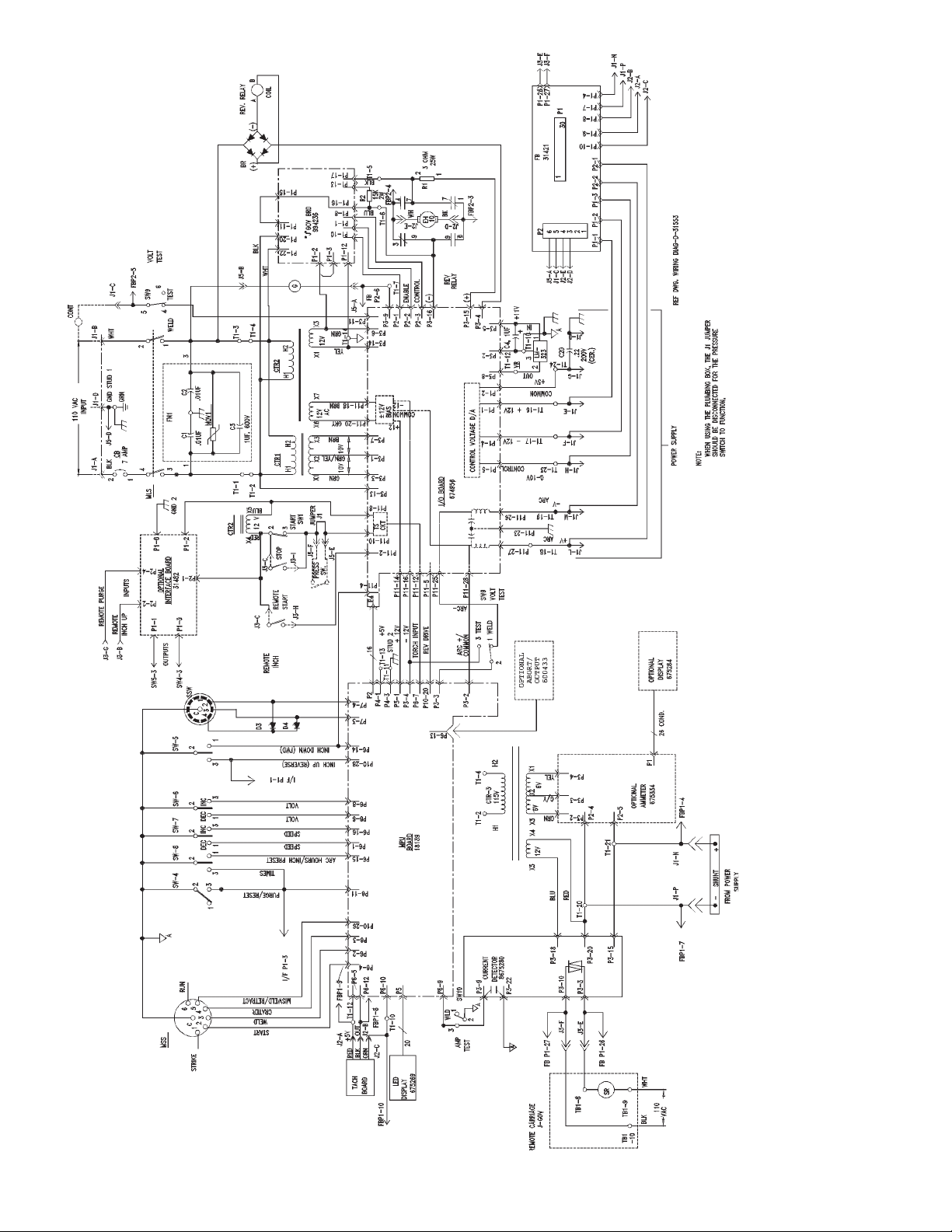
D-31552
Figure 11 - Digimatic II - Schematic Diagram
22
Page 23
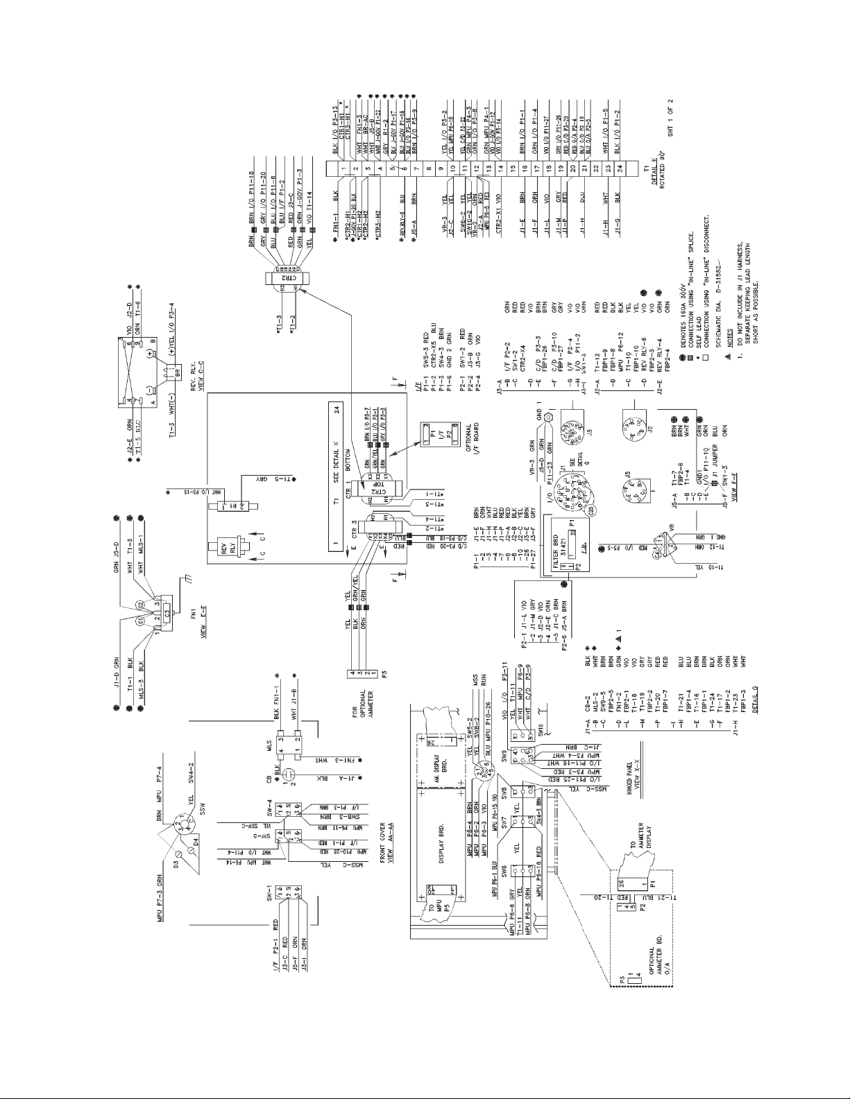
D-31553
Figure 12 - Digimatic II - Wiring Diagram, Sht. 1 of 2
23
Page 24
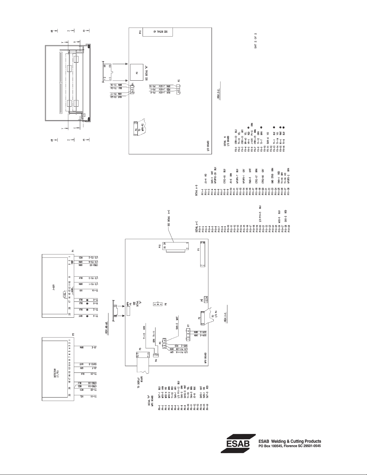
D-31553
F-15-240-A 4/97 Printed in the U.S.A.
Figure 13 - Digimatic II - Wiring Diagram, Sht. 2 of 2
 Loading...