


CUTMASTER® A120
OUTPUT MAX OUTPUT INPUT POWER
VOLTAGEVOLTAGEVOLTAGE
INPUT POWER
VOLTAGE
AUTOMATED PLASMA CUTTING SYSTEM
Operating
Manual
Revision: AA Issue Date: August 30, 2015 Manual No.: 0-5430
120
AMPS
PHASE PHASE
Art # A-12879
380-400V208-230V
esab.eu
600V460V

WE APPRECIATE YOUR BUSINESS!
Congratulations on your new ESAB product. We are proud to have you as our customer
and will strive to provide you with the best service and reliability in the industry. This product is backed by our extensive warranty and world-wide service network. To locate your
nearest distributor or service agency, visit us on the web at www.esab.eu.
This Operating Manual has been designed to instruct you on the correct use and operation of your ESAB product. Your satisfaction with this product and its safe operation is
our ultimate concern. Therefore please take the time to read the entire manual, especially
the Safety Precautions. They will help you to avoid potential hazards that may exist when
working with this product.
YOU ARE IN GOOD COMPANY!
The Brand of Choice for Contractors and Fabricators Worldwide.
ESAB is a Global Brand of manual and automation Plasma Cutting Products.
We distinguish ourselves from our competition through market-leading, dependable
products that have stood the test of time. We pride ourselves on technical innovation,
competitive prices, excellent delivery, superior customer service and technical support,
together with excellence in sales and marketing expertise.
Above all, we are committed to developing technologically advanced products to achieve
a safer working environment within the welding industry.

WARNING
!
Read and understand this entire Manual and your employer’s safety practices before installing, operating, or servicing the equipment.
While the information contained in this Manual represents the Manufacturer's best judgement,
the Manufacturer assumes no liability for its use.
Plasma Cutting Power Supply
Cutmaster® A120
SL100 1Torch™
Operating Manual Number 0-5430
Published by:
ESAB Group Inc.
2800 Airport Rd.
Denton, TX 76208
(940) 566-2000
www.esab.eu
Copyright 2015 by ESAB
All rights reserved.
Reproduction of this work, in whole or in part, without written permission of the publisher is
prohibited.
The publisher does not assume and hereby disclaims any liability to any party for any loss or
damage caused by any error or omission in this Manual, whether such error results from negligence, accident, or any other cause.
For Printing Material Specification refer to document 47x1909
Original Publication Date: August 30, 2015
Revision Date:
Record the following information for Warranty purposes:
Where Purchased:_______________________________ __________________
Purchase Date:__________________________________ __________________
Power Supply Serial #:___________________________ ___________________
Torch Serial #:___________________________________ _________________
i

Be sure this information reaches the operator.
You can get extra copies through your supplier.
CAUTION
These INSTRUCTIONS are for experienced operators. If you are not fully familiar
with the principles of operation and safe practices for arc welding and cutting equipment, we urge you to read our booklet, “Precautions and Safe Practices for Arc
Welding, Cutting, and Gouging,” Form 52-529. Do NOT permit untrained persons to
install, operate, or maintain this equipment. Do NOT attempt to install or operate this
equipment until you have read and fully understand these instructions. If you do not
fully understand these instructions, contact your supplier for further information. Be
sure to read the Safety Precautions before installing or operating this equipment.
USER RESPONSIBILITY
This equipment will perform in conformity with the description thereof contained in this manual and
accompanying labels and/or inserts when installed, operated, maintained and repaired in accordance with
the instructions provided. This equipment must be checked periodically. Malfunctioning or poorly maintained
equipment should not be used. Parts that are broken, missing, worn, distorted or contaminated should be
replaced immediately. Should such repair or replacement become necessary, the manufacturer recommends
that a telephone or written request for service advice be made to the Authorized Distributor from whom it
was purchased.
This equipment or any of its parts should not be altered without the prior written approval of the manufacturer. The user of this equipment shall have the sole responsibility for any malfunction which results from
improper use, faulty maintenance, damage, improper repair or alteration by anyone other than the manufacturer or a service facility designated by the manufacturer.
!
READ AND UNDERSTAND THE INSTRUCTION MANUAL BEFORE INSTALLING OR
OPERATING.
PROTECT YOURSELF AND OTHERS!


TABLE OF CONTENTS
SECTION 1: SAFETY ...............................................................................................................1-1
1.0 Safety Precautions......................................................................................1-1
SECTION 2 SYSTEM: INTRODUCTION .................................................................................2-1
2.01 How To Use This Manual............................................................................2-1
2.02 Equipment Identification .............................................................................2-1
2.03 Receipt Of Equipment ................................................................................2-1
2.04 Power Supply Specifications ......................................................................2-2
2.05 Input Wiring Specifications .........................................................................2-3
2.06 Power Supply Features ..............................................................................2-4
SECTION 2 TORCH: INTRODUCTION .............................................................................. 2T-1
2T.01 Scope of Manual.......................................................................................2T-1
2T.02 General Description ..................................................................................2T-1
2T.03 Specifications ..........................................................................................2T-1
2T.04 Options And Accessories .........................................................................2T-2
2T.05 Introduction to Plasma .............................................................................2T-2
SECTION 3 SYSTEM: INSTALLATION .................................................................................3-1
3.01 Unpacking...................................................................................................3-1
3.02 Lifting Options ............................................................................................3-1
3.03 Power Supply location and Mounting ........................................................3-1
3.04 Opening the Contactor Cover ....................................................................3-1
3.05 Primary Input Power Connections ..............................................................3-1
3.06 Gas Connections ........................................................................................3-3
SECTION 3 TORCH: INSTALLATION ................................................................................. 3T-1
3T.01 Torch Connections ...................................................................................3T-1
3T.02 CNC Connection.......................................................................................3T-1
3T.03 Automation Interface PCB with Ohmic Sense ..........................................3T-2
3T.04 Setting Up Automation or Machine Torch ................................................3T-3
SECTION 4 SYSTEM: OPERATION .......................................................................................4-1
4.01 Front Panel Controls / Features ..................................................................4-1
4.02 Preparations for Operation .........................................................................4-2
SECTION 4 TORCH: OPERATION ...................................................................................... 4T-1
4T.01 Machine and Automated Torch Operation ...............................................4T-1
4T.02 Automation Torch Parts Selection ............................................................4T-1
4T.03 Machine and Hand Torch Parts Selection ................................................4T-2
4T.04 Cut Quality ................................................................................................4T-3
4T.05 General Cutting Information .....................................................................4T-3
4T.06 Hand Torch Operation ..............................................................................4T-4
4T.07 Gouging ....................................................................................................4T-7
4T.08 Recommended Cutting Speeds for Machine and
Automated Torches With Exposed Tip .....................................................4T-8
4T.09 Recommended Cutting Speeds for Machine and
Automated Torches With Shielded Tip ...................................................4T-40

TABLE OF CONTENTS
PATENT INFORMATION .................................................................................................... 4T-70
SECTION 5 SYSTEM: SERVICE .............................................................................................5-1
5.01 General Maintenance ..................................................................................5-1
5.02 Maintenance Schedule ...............................................................................5-2
5.03 Common Faults ..........................................................................................5-2
5.04 Fault Indicator .............................................................................................5-3
5.05 Basic Troubleshooting Guide .....................................................................5-4
5.06 Power Supply Basic Parts Replacement ....................................................5-6
SECTION 5 TORCH: SERVICE ............................................................................................ 5T-1
5T.01 General Maintenance ................................................................................5T-1
5T.02 Inspection and Replacement of Consumable Torch Parts .......................5T-2
SECTION 6: PARTS LISTS .....................................................................................................6-1
6.01 Introduction ................................................................................................6-1
6.02 Ordering Information...................................................................................6-1
6.03 Power Supply Replacement .......................................................................6-1
6.04 Replacement Power Supply Parts ..............................................................6-2
6.05 Options and Accessories ............................................................................6-2
6.06 Torch Replacement Parts SL100SV Torch
(with Solenoid on Mounting Tube) ....................................................6-4
6.07 Torch Consumable Parts (SL100) ...............................................................6-6
6.08 Replacement Parts for Hand Torch ...........................................................6-7
APPENDIX 1: SEQUENCE OF OPERATION
(BLOCK DIAGRAM) ....................................................................................................... A-1
APPENDIX 2: DATA TAG INFORMATION ........................................................................... A-2
APPENDIX 3: TORCH PIN - OUT DIAGRAMS .................................................................... A-4
APPENDIX 4: TORCH CONNECTION DIAGRAMS ............................................................. A-6
APPENDIX 5: SYSTEM SCHEMATIC, 208/460V UNITS ..................................................... A-8
APPENDIX 6: SYSTEM SCHEMATIC, 400/600V UNITS ................................................... A-10
APPENDIX 7: RAW ARC VOLTAGE .................................................................................. A-12
Revision History ................................................................................................................... A-14


CUTMASTER A120
SECTION 1: SAFETY
1.0 Safety Precautions
Users of ESAB welding and plasma cutting equipment have the ultimate responsibility for ensuring that anyone who works
on or near the equipment observes all the relevant safety precautions. Safety precautions must meet the requirements that
apply to this type of welding or plasma cutting equipment. The following recommendations should be observed in addition
to the standard regulations that apply to the workplace.
All work must be carried out by trained personnel well acquainted with the operation of the welding or plasma cutting
equipment. Incorrect operation of the equipment may lead to hazardous situations which can result in injury to the operator
and damage to the equipment.
1. Anyone who uses welding or plasma cutting equipment must be familiar with:
- its operation
- location of emergency stops
- its function
- relevant safety precautions
- welding and / or plasma cutting
2. The operator must ensure that:
- no unauthorized person stationed within the working area of the equipment when it is started up.
- no one is unprotected when the arc is struck.
3. The workplace must:
- be suitable for the purpose
- be free from drafts
4. Personal safety equipment:
- Always wear recommended personal safety equipment, such as safety glasses, flame proof
clothing, safety gloves.
- Do not wear loose fitting items, such as scarves, bracelets, rings, etc., which could become
trapped or cause burns.
5. General precautions:
- Make sure the return cable is connected securely.
- Work on high voltage equipment may only be carried out by a qualified electrician.
- Appropriate fire extinguishing equipment must be clearly marked and close at hand.
- Lubrication and maintenance must not be carried out on the equipment during operation.
Dispose of electronic equipment at the recycling facility!
In observance of European Directive 2002/96/EC on Waste Electrical and Electronic Equipment and its
implementation in accordance with national law, electrical and/or electronic equipment that has reached the
end of its life must be disposed of at a recycling facility.
As the person responsible for the equipment, it is your responsibility to obtain information on approved collection stations.
For further information contact the nearest ESAB dealer.
ESAB can provide you with all necessary cutting protection and accessories.
0-5430 GENERAL INFORMATION
1-1

CUTMASTER A120
Arc welding and cutting can be injurious to yourself and others. Take
WARNING
ELECTRIC SHOCK - Can kill.
- Install and earth (ground) the welding or plasma cutting unit in accordance with
applicable standards.
- Do not touch live electrical parts or electrodes with bare skin, wet gloves or wet clothing.
- Insulate yourself from earth and the workpiece.
- Ensure your working stance is safe.
FUMES AND GASES - Can be dangerous to health.
- Keep your head out of the fumes.
- Use ventilation, extraction at the arc, or both, to take fumes and gases away from your
breathing zone and the general area.
ARC R AYS - Can injure eyes and burn skin.
- Protect your eyes and body. Use the correct welding / plasma cutting screen and filter
lens and wear protective clothing.
- Protect bystanders with suitable screens or curtains.
FIRE HAZARD
- Sparks (spatter) can cause fire. Make sure therefore that there are no inflammable
materials nearby.
precautions when welding and cutting. Ask for your employer's safety
practices which should be based on manufacturers' hazard data.
NOISE - Excessive noise can damage hearing.
- Protect your ears. Use earmuffs or other hearing protection.
- Warn bystanders of the risk.
MALFUNCTION - Call for expert assistance in the event of malfunction.
READ AND UNDERSTAND THE INSTRUCTION MANUAL BEFORE INSTALLING OR OPERATING.
PROTECT YOURSELF AND OTHERS!
Do not use the power source for thawing frozen pipes.
WARNING
Class A equipment is not intended for use in residential locations
CAUTION
CAUTION
CAUTION
where the electrical power is provided by the public low-voltage
supply system. There may be potential difficulties in ensuring
electromagnetic compatibility of class A equipment in those locations, due to conducted as well as radiated disturbances.
This product is solely intended for metal removal. Any other use
may result in personal injury and / or equipment damage.
Read and understand the instruction manual before
installing or operating.
!
1-2
GENERAL INFORMATION 0-5430

CUTMASTER A120
!
!
SECTION 2 SYSTEM:
INTRODUCTION
2.01 How To Use This Manual
This Owner’s Manual applies to just specication or part
numbers listed on page i.
To ensure safe operation, read the entire manual, including the chapter on safety instructions and warnings.
Throughout this manual, the words WARNING, CAUTION, DANGER and NOTE may appear. Pay particular attention to the information provided under these
headings. These special annotations are easily recognized as follows:
NOTE!
An operation, procedure, or background information which requires
additional emphasis or is helpful in
efcient operation of the system.
CAUTION
!
A procedure which, if not properly
followed, may cause damage to the
equipment.
2.02 EquipmentIdentication
The unit’s identication number (specication or part
number), model, and serial number usually appear on
a data tag attached to the rear panel. Equipment which
does not have a data tag such as torch and cable as-
semblies are identied only by the specication or part
number printed on loosely attached card or the shipping
container. Record these numbers on the bottom of page
i for future reference.
2.03 Receipt Of Equipment
When you receive the equipment, check it against the
invoice to make sure it is complete and inspect the
equipment for possible damage due to shipping. If there
is any damage, notify the carrier immediately to le a
claim. Furnish complete information concerning damage claims or shipping errors to the location in your area
listed in the inside back cover of this manual.
Include all equipment identication numbers as described
above along with a full description of the parts in error.
Move the equipment to the installation site before
un-crating the unit. Use care to avoid damaging the
equipment when using bars, hammers, etc., to un-crate
the unit.
WARNING
A procedure which, if not properly
followed, may cause injury to the
operator or others in the operating
area.
WARNING
Gives information regarding possible
electrical shock injury. Warnings
will be enclosed in a box such as
this.
DANGER
Means immediate hazards which, if
not avoided, will result in immediate,
serious personal injury or loss of life.
Additional copies of this manual may be purchased by
contacting ESAB at the address and phone number in
your area listed on back cover of this manual. Include
the Owner’s Manual number and equipment identication numbers.
Electronic copies of this manual can also be downloaded
at no charge in Acrobat PDF format by going to the ESAB
web site listed below
http://www.esab.eu
0-5430 INTRODUCTION
2-1
CUTMASTER A120
150 mm
2.04 PowerSupplySpecications
CutmasterA120PowerSupplySpecications
Input Power 208 / 230 VAC (187 - 253 VAC), Single Phase, 60 Hz
230 VAC (187 - 253 VAC), 3 Phase, 50/60 Hz
380 VAC (360 - 440 VAC), 3 Phase, 50/60 Hz
400 VAC (360 - 440 VAC), 3 Phase, 50 Hz
460 VAC (414 - 506 VAC), Single Phase, 60 Hz
460 VAC (414 - 506 VAC), 3 Phase, 60 Hz
600 VAC (540 - 630), 3 Phase, 60 Hz
Input Power Cable Power Supply includes input cable.
Output Current 30 - 120 Amps, Continuously Adjustable
Power Supply Gas Filtering Ability Particulates to 5 Microns
Cutmaster A120 Power Supply Duty Cycle *
Ambient Temperature Duty Cycle Ratings @ 40° C (104° F)
Operating Range 0° - 50° C
All Units IEC
Duty Cycle **60% 80% 100%
Current 120 120 100
DC Voltage 128 128 120
* NOTE: The duty cycle will be reduced if the primary input power (AC) is low or the output voltage
(DC) is higher than shown in this chart.
** 60% at 208/230V 1-Phase Input ONLY
NOTE!
IEC Rating is determined as specied by the International Electro-Technical Commission. These
specications include calculating an output voltage based upon power supply rated current. To fa-
cilitate comparison between power supplies, all manufacturers use this output voltage to determine
duty cycle.
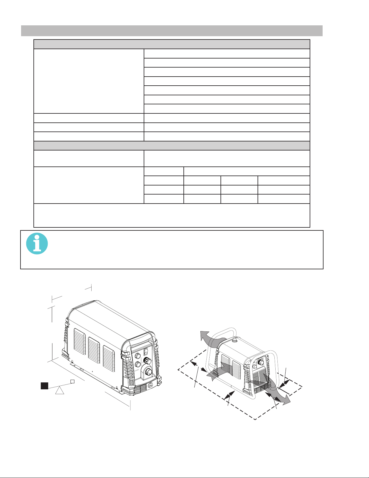
Power Supply Dimensions & Weight Ventilation Clearance Requirements
10"
254 mm
Art # A-08459
13.78"
350 mm
63 lb / 28.6 kg
26.3"
0.668 m
24"
610 mm
Art # A-07925_AB
6"
150 mm
6"
INTRODUCTION 0-5430
2-2
150 mm
6"

CUTMASTER A120
2.05 InputWiringSpecications
Cutmaster A120 Power Supply Input Cable Wiring Requirements
Input
voltage
Volts Hz kVA I max I eff Fuse
1 Phase 208 60 26.2 126 98 150 4 Type W 25 Type W
230 60 27.6 118 95 125 4 Type W 25 Type W
460 60 35 76 68 100 4 25
3 Phase 208 60 21.6 60 55 60 4 25
230 60 22.3 56 50 60 4 25
380 50 23 35 32 40 8 10
400 50 23.6 34 31 40 8 10
460 60 29.5 37 33 40 8 10
600 60 29.0 28 25 30 10 6
NOTE!
Refer to Local and National Codes or local authority having jurisdiction for proper wiring requirements.
The suggested sizes are based on exible power cable with power plug installations. For hard-
wired installations refer to local or national codes.
I1max is taken at TDC rated minimum duty cycle.
I1eff is taken at TDC 100% rated duty cycle
Freq Power
Input
(amps)
Line Voltages with Suggested Circuit Protection and Wire Sizes
Based on National Electric Code and Canadian Electric Code
Suggested Sizes
Flexible Cord
(Min. AWG)
Flexible Cord
(Min. mm2)
0-5430 INTRODUCTION
2-3

CUTMASTER A120
Ar
rk Cable
and Clamp
Input Power Cord
Input
Art # A-08461
2.06 Power Supply Features
t # A-08460
Mounting Rails
Automation Interface
Cable Port
Power Selection
Control Panel
Torch Leads
Receptacle
Wo
Filter Assembly
Gas Inlet Port
INTRODUCTION 0-5430
2-4

SECTION 2 TORCH:
44.5 mm
18.875" / 479 mm
16 mm
1.175" / 30 mm
2.875”
73 mm
t # A-02998
15.875" / 403 mm
16 mm
(95 mm)
INTRODUCTION
CUTMASTER A120
The standard automation torch has a positioning tube with rack & pinch block assembly and a
solenoid valve.
2T.01 Scope of Manual
This manual contains descriptions, operating instructions
and maintenance procedures for the 1Torch Models
SL100/Manual and SL100/Mechanized Plasma Cutting
Torches. Service of this equipment is restricted to prop-
erly trained personnel; unqualied personnel are strictly
cautioned against attempting repairs or adjustments not
covered in this manual, at the risk of voiding the Warranty.
Read this manual thoroughly. A complete understanding
of the characteristics and capabilities of this equipment
will assure the dependable operation for which it was
designed.
2T.02 General Description
Plasma torches are similar in design to the automotive
spark plug. They consist of negative and positive sections separated by a center insulator. Inside the torch,
the pilot arc starts in the gap between the negatively
charged electrode and the positively charged tip. Once
the pilot arc has ionized the plasma gas, the superheated
column of gas ows through the small orice in the torch
tip, which is focused on the metal to be cut.
/
1.75" /
0.625" /
12.285" / 312 mm
1.375" / 35 mm
4.95" / 126 mm
Art # A-07402_AC
2. Machine Torch, Model
The standard machine torch has a positioning
tube with rack & pinch block assembly.
9.285" / 236 mm
1.375" / 35 mm
1.75" /
44.5 mm
0.625" /
4.95" / 126 mm
1.175" / 30 mm
Ar
3. Hand/Manual Torch, Models
The hand torch head is at 75° to the torch handle.
The hand torches include a torch handle and torch
trigger assembly.
10.125" (257 mm)
A single torch lead provides gas from a single source to
be used as both the plasma and secondary gas. The
air ow is divided inside the torch head. Single - gas
operation provides a smaller sized torch and inexpensive
operation.
NOTE!
Refer to Section "2T.05 Introduction
to Plasma" on page 2T-2, for a more
detailed description of plasma torch
operation.
Refer to the Appendix Pages for ad-
ditional specications as related to the
Power Supply used.
2T.03 Specications
A. TorchCongurations
1. Automation Torch, Model
3.75"
Art # A-03322_AB
1.17" (29 mm)
B. Torch Leads Lengths
Hand Torches are available as follows:
• 20 ft / 6.1 m, with ATC connectors
• 50 ft / 15.2 m, with ATC connectors
Machine / Automation Torches are available as
follows:
• 5 foot / 1.5 m, with ATC connectors
• 10 foot / 3.05 m, with ATC connectors
• 25 foot / 7.6 m, with ATC connectors
• 50 foot / 15.2 m, with ATC connectors
C. Torch Parts
Starter Cartridge, Electrode, Tip, Shield Cup
D. Parts - In - Place (PIP)
Torch Head has built - in switch
0-5430 INTRODUCTION
2T-1
CUTMASTER A120
!
C
12 VDC circuit rating
2T.05 Introduction to Plasma
E. Type Cooling
Combination of ambient air and gas stream through
torch.
F. Torch Ratings
Automated / Machine Torch Ratings
Ambient
Temperature
Duty Cycle
Maximum Current 120 Amps
Voltage (V
Arc Striking Voltage 7kV
Ambient
Temperature
Duty Cycle 100% @ 120 Amps @ 400 scfh
Maximum Current 120 Amps
Voltage (V
Arc Striking Voltage 7kV
peak
Manual Torch Ratings
peak
100% @ 100 Amps @ 400 scfh
80% @ 120 Amps @ 400 scfh
) 500V
) 500V
104° F
40° C
104° F
40° C
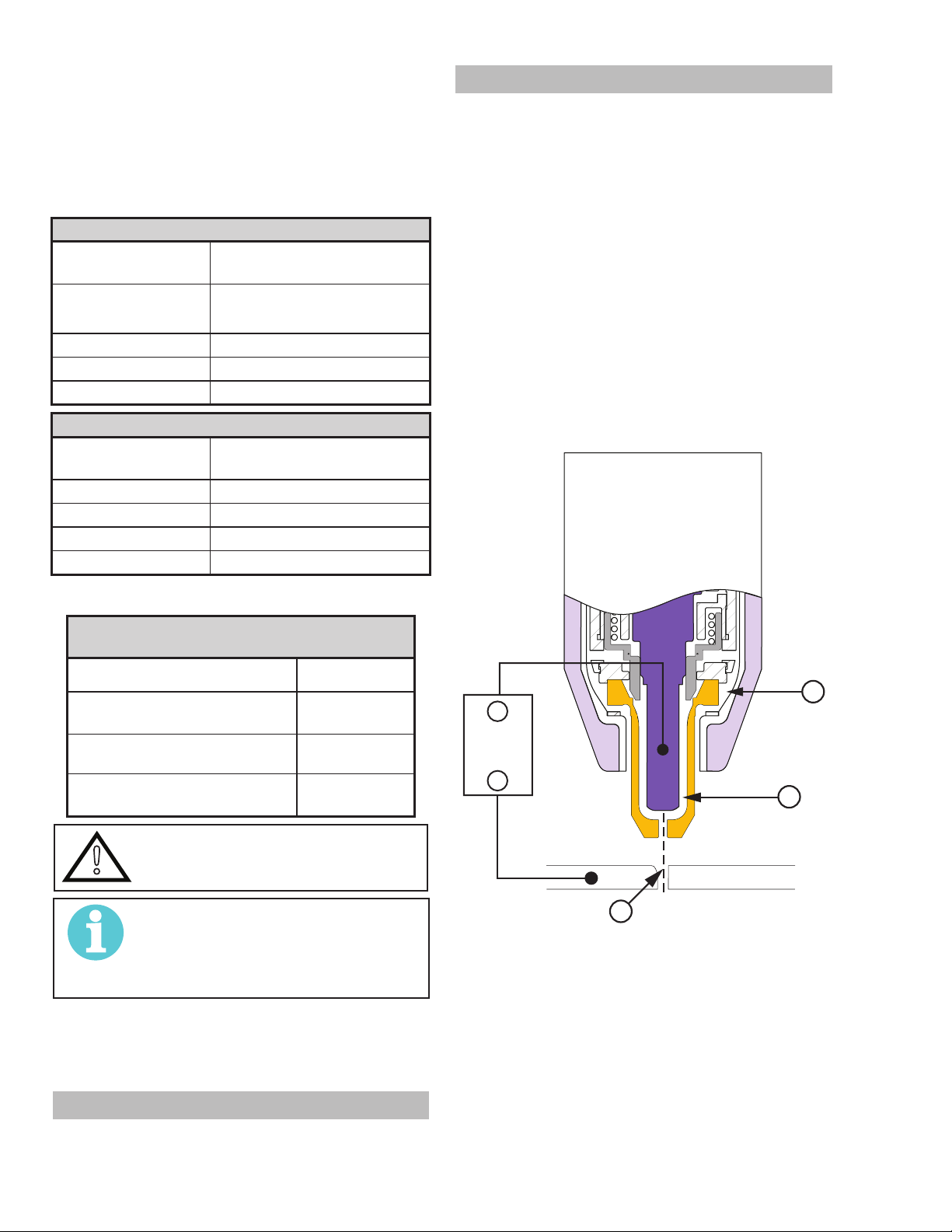
A. Plasma Gas Flow
Plasma is a gas which has been heated to an
extremely high temperature and ionized so that it
becomes electrically conductive. The plasma arc
cutting and gouging processes use this plasma to
transfer an electrical arc to the workpiece. The metal
to be cut or removed is melted by the heat of the arc
and then blown away.
While the goal of plasma arc cutting is separation of
the material, plasma arc gouging is used to remove
metals to a controlled depth and width.
In a Plasma Cutting Torch a cool gas enters Zone B,
where a pilot arc between the electrode and the torch
tip heats and ionizes the gas. The main cutting arc
then transfers to the workpiece through the column
of plasma gas in Zone C.
G. Gas Requirements
Automated, Manual and Machine Torch Gas
Specications
Gas (Plasma and Secondary) Compressed Air
Operating Pressure
Refer to NOTE
Maximum Input Pressure 125 psi / 8.6 bar
Gas Flow (Cutting and
Gouging)
60 - 95 psi
4.1 - 6.5 bar
300 - 500 scfh
142 - 235 lpm
WARNING
This torch is not to be used with
oxygen (O2).
NOTE!
Operating pressure varies with torch
model, operating amperage, and torch
leads length. Refer to gas pressure settings charts for each model.
H. Direct Contact Hazard
For standoff tip the recommended standoff is 3/16
inches / 4.7 mm.
_
Power
Supply
+
B
Workpiece
A-08331
Typical Torch Head Detail
By forcing the plasma gas and electric arc through a
small orice, the torch delivers a high concentration
of heat to a small area. The stiff, constricted plasma
arc is shown in Zone C. Direct current (DC) straight
polarity is used for plasma cutting, as shown in the
illustration.
A
2T.04 Options And Accessories
For options and accessories, see section 6.
INTRODUCTION 0-5430
2T-2
Zone A channels a secondary gas that cools the
torch. This gas also assists the high velocity plasma

gas in blowing the molten metal out of the cut allow-
up
To
up
up
Remote Pendant
To
A-02997
r
ing for a fast, slag - free cut.
B. Gas Distribution
CUTMASTER A120
The single gas used is internally split into plasma
and secondary gases.
The plasma gas ows into the torch through the
negative lead, through the starter cartridge, around
the electrode, and out through the tip orice.
The secondary gas ows down around the outside
of the torch starter cartridge, and out between the
tip and shield cup around the plasma arc.
C. Pilot Arc
When the torch is started a pilot arc is established
between the electrode and cutting tip. This pilot arc
creates a path for the main arc to transfer to the work.
D. Main Cutting Arc
DC power is also used for the main cutting arc. The
negative output is connected to the torch electrode
through the torch lead. The positive output is connected to the workpiece via the work cable and to
the torch through a pilot wire.
E. Parts - In - Place (PIP)
AT C
AT C
To AT C
PIP Sw itch
CNC Start
PIP Sw itch
Automation To rch
PIP Sw itch
Sh ield C
Sh ield C
Art # A-08168
Sh ield C
Parts - In - Place Circuit Diagram for Machine Torch
The torch includes a 'Parts - In - Place' (PIP) circuit.
When the shield cup is properly installed, it closes
a switch. The torch will not operate if this switch is
open.
To Control
Torch Switch
Cable Wiring
PIP Switch
Torch Trigge
Shield Cup
Parts - In - Place Circuit Diagram for Hand Torch
0-5430 INTRODUCTION
2T-3

CUTMASTER A120
This Page Intentionally Blank
INTRODUCTION 0-5430
2T-4

SECTION 3 SYSTEM:
!
Art# A-11478
INSTALLATION
CUTMASTER A120
2. Place the unit in the desired position and mark
where the four keyway holes in the mounting rails
touch.
3.01 Unpacking
1. Use the packing lists to identify and account for
each item.
2. Inspect each item for possible shipping damage.
If damage is evident, contact your distributor and
/ or shipping company before proceeding with the
installation.
3. Record Power Supply and Torch model and serial
numbers, purchase date and vendor name, in the
information block at the front of this manual.
3.02 Lifting Options
The Power Supply includes hand holds in the front and
rear panels for hand lifting only. Be sure unit is lifted
and transported safely and securely.
WARNING
Do not touch live electrical parts.
Disconnect input power cord before
moving unit.
FALLING EQUIPMENT can cause
serious personal injury and can damage
equipment.
3. Remove the unit and using these markings,
prepare holes for mounting hardware.
4. Insert proper hardware. If using hardware that
screws into the mounting surface, leave all four
loose enough for the thickness of the rail to slide
under the head and washer if used.
5. Lower the power supply over the mounting
hardware and slide forward or backward until the
keyway stops against the mounting hardware.
6. Secure the hardware to the rail.
3.04 Opening the Contactor Cover
The input power cord is connected to the main contactor, the contactor is located inside a box with a snap on
cover. The cover is held in place with two or more snap
lock tabs. To remove the cover release the front latch and
tilt the cover up about ½ inch. Then squeeze both sides
of the cover and lift it straight up. See the Primary Input
Power Connections section for the necessary changes
to the Contactor. Remember to replace the Contactor
Cover when the changes are complete.
• Only persons of adequate physical strength should
lift the unit.
• Lift unit by the handles, using two hands. Do not
use straps for lifting.
• Use optional cart or similar device of adequate
capacity to move unit.
• Place unit on a proper skid and secure in place
before transporting with a fork lift or other vehicle.
3.03 Power Supply location and Mounting
NOTE!
It is recommended that the unit be
secured to a suitable surface using the
mounting rails.
1. First choose an appropriate location for mounting the power supply. Choose one that allows
for free movement of torch leads, complies with
ventilation per section 2.04 and provides a safe
rm surface where the unit can be secured.
1
2
1
2
Contactor cover
3.05 Primary Input Power Connections
CAUTION
!
Check your power source for correct
voltage before plugging in or connecting
the unit. Check the Voltage Selector at
the rear of the unit for correct setting before plugging in or connecting the unit.
The primary power source, fuse, and
any extension cords used must conform
to local electrical code and the recommended circuit protection and wiring
requirements as specied in Section 2.
0-5430 INSTALLATION
3-1

CUTMASTER A120
Screws
Art # A-08316
Art # A-08493
Most units are shipped from the factory with a 230 Volt
input power cable wired to the input contactor in the
single - phase conguration. The following illustrations
and directions are for changing that conguration to a
different voltage and or to three - phase operation or back
again if a change had already been made.
A. Cover Removal
1. Remove the upper and lower screws which
secure the cover to the main assembly. Do not
loosen the lower screws inside the cut out slots
in the bottom of the cover.
NOTE!
The upper screws and lower screws
are not the same. Do not mix them.
The upper screws are for threading into
the plastic of the front and rear panels.
DO NOT use the ner threaded lower
screws for this.
NOTE!
When installing the upper screws, attempt to reuse the original threads. The
easiest way to do this is by turning the
screw counter-clockwise until you feel
the threads line up, then begin to turn
the screw clockwise to tighten. Do not
over tighten.
C. Input Power Selection
Set the Input Voltage Selection Switch at the rear of the
unit based on the primary input voltage it is connected
to. Low is 208/230 VAC and high is 460 VAC.
LO
HI
S
Upper
Screws
Lower
Slots
Lower
Screws
Art # A-08429
2. Carefully pull the Cover up and away from the
unit.
B. Cover Installation
D. Quick Guide to Phase Wiring
The following illustration and directions are for changing
phase of the power supply.
Input Power Cable Connections
Single-Phase (1ø) and Jumper Settings
Store copper jumpers on base plate
L1
L2
L3
L4
GND
Three-Phase (3ø)
L1
L2
L3
L4
GND
Single and Three Phase Input Power Wiring
NOTE!
There are two jumpers used for the
single phase 230V setting and none for
three phase.
E. Connections to Single Phase Input Power
WARNING
!
Disconnect input power from the power
supply and input cable before attempting this procedure.
1. Reverse previous procedures for cover installation.
These instructions are for changing the input power and
or cable on the 208/230, 400, 460 VAC Power Supply to
Single - Phase input power.
INSTALLATION 0-5430
3-2

1. Remove the Power Supply cover.
!
See "A. Cover Removal".
2. Disconnect the original input power cable from
the main input contactor and the chassis ground
connection.
3. Loosen the through-hole protector on the back
panel of the power supply. Pull the original power
cable out of the power supply.
4. If the power cable being used is not the factory
- supplied cable, use a three - conductor input
power cable for the voltage desired and strip back
the insulation on the individual wires.
5. Pass the cable being used through the access
opening in the back panel of the power supply.
Refer to Section 2 for power cable specications.
CAUTION
!
6. Connect the wires as follows.
7. With a little slack in the wires, tighten the through
8. Reinstall the Power Supply cover.
9. Connect the opposite end of individual wires to
10. Connect the input power cable (or close the main
F. Connections to Three Phase Input Power
The primary power source and power
cable must conform to local electrical
code and the recommended circuit pro-
tection and wiring requirements (refer to
table in Section 2).
• Connect Bus Bar Jumpers on the contactor
as shown in prior illustration and on label in
the power supply.
• Green / Yellow wire to Ground.
- hole protector to secure the power cable.
See "B. Cover Installation".
a customer supplied plug or main disconnect.
disconnect switch) to supply power.
CUTMASTER A120
3. Loosen the through-hole protector on the back
panel of the power supply. Pull the original power
cable out of the power supply.
4. Using a customer supplied four - conductor input
power cable for the voltage desired, strip back
the insulation on the individual wires.
5. Pass the cable being used through the access
opening in the back panel of the power supply.
Refer to Section 2 for power cable specications.
CAUTION
!
6. Connect the wires as follows.
7. With a little slack in the wires, tighten the through
8. Reinstall the Power Supply cover. See "B.
9. Connect the opposite end of individual wires to
10. Connect the input power cable (or close the main
3.06 Gas Connections
Connecting Gas Supply to Unit
The connection is the same for compressed air or high
pressure cylinders. Refer to the following subsections
if an optional air line lter is to be installed.
The primary power source and power
cable must conform to local electrical
code and the recommended circuit pro-
tection and wiring requirements (refer to
table in Section 2).
• Wires to L1, L2 and L3 input. It does not
matter what order these wires are attached.
See previous illustration and on label in the
power supply.
• Green / Yellow wire to Ground.
- hole protector to secure the power cable.
Cover Installation".
a customer supplied plug or main disconnect.
disconnect switch) to supply power.
WARNING
Disconnect input power from the power
supply and input cable before attempting this procedure.
These instructions are for changing the input power and
or cable on the 208/230, 400, 460 VAC Power Supply to
Three - Phase input power.
1. Remove the Power Supply cover.
See "A. Cover Removal".
2. Disconnect the original input power cable from
the main input contactor and the chassis ground
connection.
0-5430 INSTALLATION
1. Connect the air line to the inlet port. The illustra-
tion shows typical ttings as an example.
NOTE!
For a secure seal, apply thread seal-
ant to the tting threads, according
to the manufacturer's instructions.
Do Not use Teon tape as a thread
sealer, as small particles of the tape
may break off and block the small air
passages in the torch.
3-3

CUTMASTER A120
rt
Filter Assembly
Gas Supply
Hose
to 1/4” (6mm) Fitting
Art # A-08319
Hose Clam
rt
Filter Assembly
Inlet Po
Hose Clamp
Art # A-08320
1/4 NPT or ISO-R
Air Connection to Inlet Port
Installing Optional Single - Stage Air Filter
An optional lter kit is recommended for improved ltering with compressed air, to keep moisture and debris
out of the torch.
1. Attach the Single - Stage Filter Hose to the Inlet
Port.
2. Attach the Filter Assembly to the lter hose.
3. Connect the air line to the Filter. The illustration
shows typical ttings as an example.
NOTE!
For a secure seal, apply thread seal-
ant to the tting threads, according
to the manufacturer's instructions.
Do Not use Teon tape as a thread
sealer, as small particles of the tape
may break off and block the small air
passages in the torch. Connect as
follows:
Inlet Po
p
Gas Supply
Hose
1/4 NPT to 1/4"
(6mm) Fitting
Optional Single - Stage Filter Installation
Using High Pressure Air Cylinders
When using high pressure air cylinders as the air supply:
1. Refer to the manufacturer’s specications for
installation and maintenance procedures for high
pressure regulators.
2. Examine the cylinder valves to be sure they are
clean and free of oil, grease or any foreign mate-
rial. Briey open each cylinder valve to blow out
any dust which may be present.
3. The cylinder must be equipped with an adjustable high - pressure regulator capable of outlet
pressures up to 100 psi (6.9 bar) maximum and
ows of at least 300 scfh (141.5 lpm).
4. Connect supply hose to the cylinder.
NOTE!
Pressure should be set at 100 psi
(6.9 bar) at the high pressure cylinder regulator.
Supply hose must be at least 1/4
inch (6 mm) I.D.
For a secure seal, apply thread
sealant to the tting threads, according to manufacturer's instructions.
Do Not use Teon tape as a thread
sealer, as small particles of the tape
may break off and block the small air
passages in the torch.
INSTALLATION 0-5430
3-4
Installing Optional Two - Stage Air Filter Kit
This optional two - stage air line lter is also for use on
compressed air shop systems. Filter removes moisture
and contaminants to at least 5 microns.

Connect the air supply as follows:
Regulator/Filter
wo Stage
Art # A-07945_AC
Hose Clamp
1. Attach the Two Stage Filter bracket to the back
of the power supply per instructions supplied with
the lter assembly.
NOTE!
For a secure seal, apply thread
sealant to the tting threads according to manufacturer's instructions.
Do Not use Teon tape as a thread
sealer as small particles of the tape
may break off and block the small air
passages in the torch.
2. Connect the two stage lter outlet hose to the
inlet port of the Regulator / Filter Assembly.
3. Use customer - supplied ttings to connect the air
line to the Filter. A 1/4 NPT to 1/4" hose barbed
tting is shown as an example.
CUTMASTER A120
NOTE!
Pressure should be set at 100 psi
(6.9 bar) at the high pressure cylinder regulator.
Supply hose must be at least 1/4
inch (6 mm) I.D.
For a secure seal, apply thread
sealant to the tting threads, according to manufacturer's instructions.
Do Not use Teon tape as a thread
sealer, as small particles of the tape
may break off and block the small air
passages in the torch.
Assembly
Regulator
Input
Gas Supply
Hose
1/4 NPT to 1/4”
(6mm) Fitting
2-Stage Filter
Inlet Port (IN)
Outlet Port
(OUT)
T
Filter
Assembly
Optional Two - Stage Filter Installation
Using High Pressure Air Cylinders
When using high pressure air cylinders as the air supply:
1. Refer to the manufacturer’s specications for
installation and maintenance procedures for high
pressure regulators.
2. Examine the cylinder valves to be sure they are
clean and free of oil, grease or any foreign mate-
rial. Briey open each cylinder valve to blow out
any dust which may be present.
3. The cylinder must be equipped with an adjustable high - pressure regulator capable of outlet
pressures up to 100 psi (6.9 bar) maximum and
ows of at least 300 scfh (141.5 lpm).
4. Connect supply hose to the cylinder.
0-5430 INSTALLATION
3-5

CUTMASTER A120
This Page Intentionally Blank
INSTALLATION 0-5430
3-6

CUTMASTER A120
A
Cab
Art # A-08464
Art # A-08323_AB
Plasma
Divided
oltage
SECTION 3 TORCH:
INSTALLATION
3T.01 Torch Connections
If necessary, connect the torch to the Power Supply.
Connect only the ESAB model SL100SV / Automation,
SL100 / Mechanical or SL100 / Manual Torch to this
power supply. Maximum torch leads length is 100 feet
/ 30.5 m, including extensions.
WARNING
Disconnect primary power at the source
before connecting the torch.
1. Align the ATC male connector (on the torch lead)
with the female receptacle. Push the male connector into the female receptacle. The connectors should push together with a small amount
of pressure.
2. Secure the connection by turning the locking nut
clockwise until it clicks. DO NOT use the locking
nut to pull the connection together. Do not use
tools to secure the connection.
3T.02 CNC Connection
1. Locate the interface connection port on the rear
of the power supply.
utomation Interface
le Port
2. Note the pin-out of the connector and that the
customer supplied connector matches.
Start / Stop
Signal
Arc
V
Art # A-07885
Connecting the Torch to the Power Supply
3. The system is now ready for operation.
Check Air Quality
To test the quality of air:
1. Put the ON / OFF switch in the ON (up)
position.
2. Put the Function Control switch in the SET
position.
3. Place a welding lter lens in front of the torch and
turn ON the air. Do not start an arc!
Any oil or moisture in the air will be visible on the lens.
Cutting Machine
OK to Move
2
1
0-5430 INSTALLATION
3T-1

CUTMASTER A120
GND
-12V
3T.03 Automation Interface PCB with Ohmic Sense
The new Automation Interface PCB with Ohmic Sense adds additional selectable divided voltage ratios and
selectable polarity of the divided signal. The board also has Ohmic sensing for use with the iHC XT via
either the exposed torch tip or via a separate Shield Cup using the Ohmic clip. The ohmic sensing will also
provide collision sensing when used with the iHC XT or iCNC.
Signals at the CNC connector (J1 on this board) are START / STOP on J1-3 (common) and J1-4 (+); Isolated
& Divided Arc voltage on J1-5 (-) and J1-6 (+); PLATE CONTACT OUT (relay contact) between J1-10 and
J1-11; OK TO MOVE OUT (relay contact) between J1-12 and J1-14.
Voltage divider;
The 6 position DIP switch, DIV1, makes available the following divide ratios:
DIV1-1 ON = 16.7:1 for SC11; DIV1-2 ON = 20:1 for EASB; DIV1-3 ON = 30:1;
DIV1-4 ON = 40:1 for Inova; DIV1-5 ON = 50:1 for IHT, SC3000 & 3100; Hypertherm®;
DIV1-6 ON = 80:1 for TD iHC
NOTE!
Only one position should be on at a time.
Divided arc voltage signal is isolated, either the positive signal (J1-6) or negative (J1-5) may be grounded
or both can be oating.
Ohmic sensing and Collision via exposed TIP:
With a connection made from the PCB4 terminal TIP to the main board PCB1 terminal TIP1 contact of the
exposed tip with the work while nding height is sensed and activates the signal PLATE CONTACT OUT at
J1-11. SW2 set to 0 can disable this sensing.
During cutting the exposed tip contacting the work will close the relay contact between J1-10 and J1-11
which is interpreted by the iHC as a collision. This feature may be disabled by setting SW3 to 0.
NOTE!
If TIP1 on PCB1 (main board) is not connected to TIP terminal on PCB4 both SW2 and SW3 must
be set to “0” (off) position else the plate contact signal will be active all the time.
Ohmic sensing and Collision via shield cup Ohmic Clip.
The Plasma Adapter Cable for use with the iHC XT for this Automation Interface PCB with Ohmic Sense
includes a connection to pin 13 which can be connected to a wire from the ohmic clip. Note that this adapter
cable is different from the one used with the separate iHC voltage divider board. When the shield cup, with
contact from the ohmic clip, contacts work during height nding it closes the relay between J1-10 and J1-11
providing the PLATE CONTACT signal to the iHC. During cutting the iHC interprets this contact as a collision
and retracts the torch.
Indicators:
LED indicators START, M-ARC and CONTACT are provided to show when START (torch trigger) is ON,
when OK to Move (M-ARC) is on, and when Plate Contact is active.
Rating:
The OK to Move and the Plate Contact Out are relay contacts rated for maximum of 30VAC or DC at 1 amp
maximum.
Start SW input requires a switch or relay contact rated for at least 12VDC at 3 ma.
START
INSTALLATION 0-5430
3T-2
J1-3
J1-4
3k

CUTMASTER A120
)
DIVIDE RATIO SET BY DIP SW DIV1
DIV1-1 ON = 16.7:1 for SC11
DIV1-2 ON = 20:1 for ESAB
DIV1-3 ON = 30:1
To -V OUT 1
on PCB1
P10
1
2
3
4
5
6
7
8
To TIP1
on PCB1
J2
*
1
2
3
4
5
6
7
8
-V0_1
+12V
START / STOP
1
TIP
1
CONTACT
VOLTAGE
DIVIDER
CIRCUITS
OK TO MOVE
DIV1-4 ON = 40:1 for Inova
DIV1-5 ON = 50:1 for IHT:
DIV1-6 ON = 80:1 for TD iHC
DIV1
123456
ISO GND
-
+
SW1
PCB4
AUTOMATION
INTERFACE PCB
(w / OHMIC)
OHMIC
SENSE
CIRCUITS
M-ARC
OK to MOVE
ISO GND
START
SC3000 & 3100; Hypertherm
J1
1
2
START / STOP (com)
3
START / STOP
4
DIVIDED ARC VOLTAGE (-)
5
DIVIDED ARC VOLTAGE (+
6
7
COMMON
8
9
PLATE CONTACT COM
CONTACT
OK TO MOVE
10
PLATE CONTACT OUT
11
OK TO MOVE
12
13
OK TO MOVE
14
Art # A-09819_AC
OHMIC
®
3. Connect CNC to the power supply.
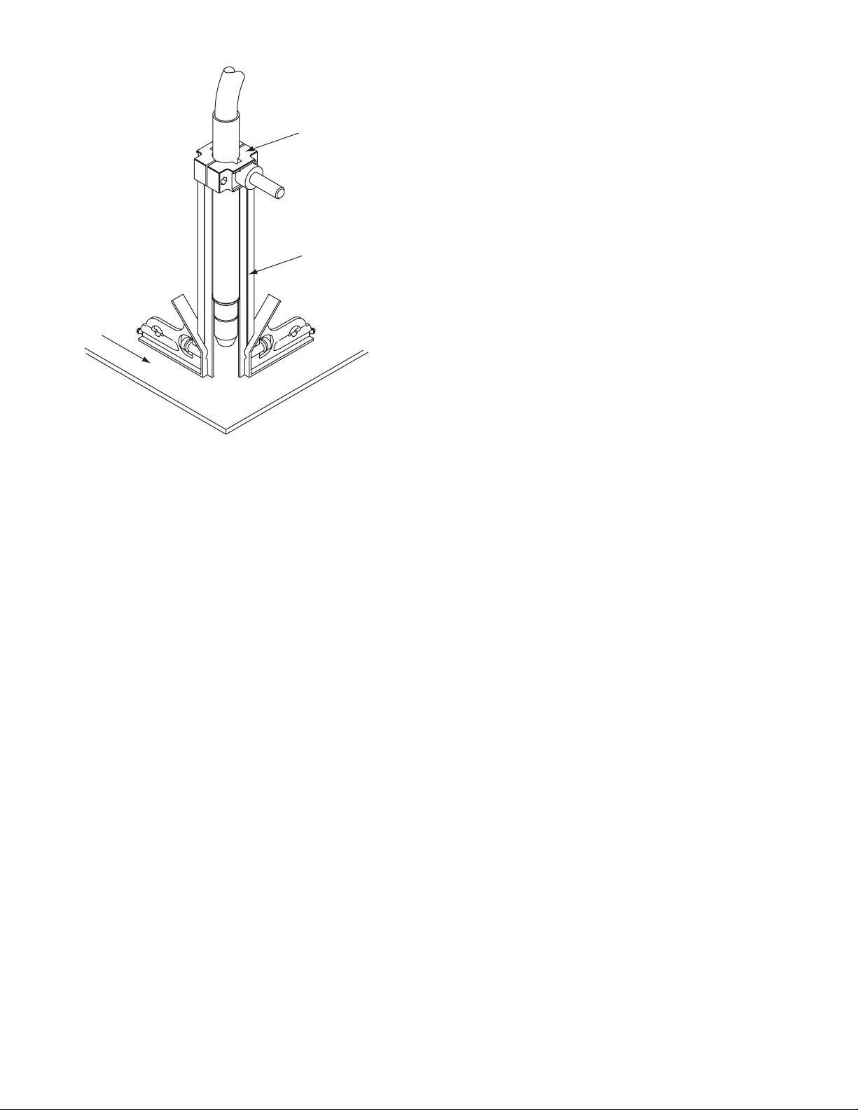
3T.04 Setting Up Automation or Machine Torch
NOTE!
An adapter is required to be installed in
the power supply if converting a hand
torch system to operate a machine or
automation torch.
The Automation and Machine torch include a positioning tube with rack and pinch block assembly.
1. Mount the torch assembly on the cutting table.
2. To obtain a clean vertical cut, use a square to align the torch perpendicular to the surface of the workpiece.
WARNING
Disconnect primary power at the source
before disassembling the torch or torch
leads.
0-5430 INSTALLATION
3T-3
CUTMASTER A120
Wo
rkpiece
Automated and Machine Torch Set - Up
Pinch Block
Assembly
Square
A-02585
3. The proper torch parts (shield cup, tip, start cartridge, and electrode) must be installed for the
type of operation. Refer to Section 4T.08, Torch
Parts Selection for details.
INSTALLATION 0-5430
3T-4
CUTMASTER A120
+
12
3
5
6
7
9
10
SECTION 4 SYSTEM:
OPERATION
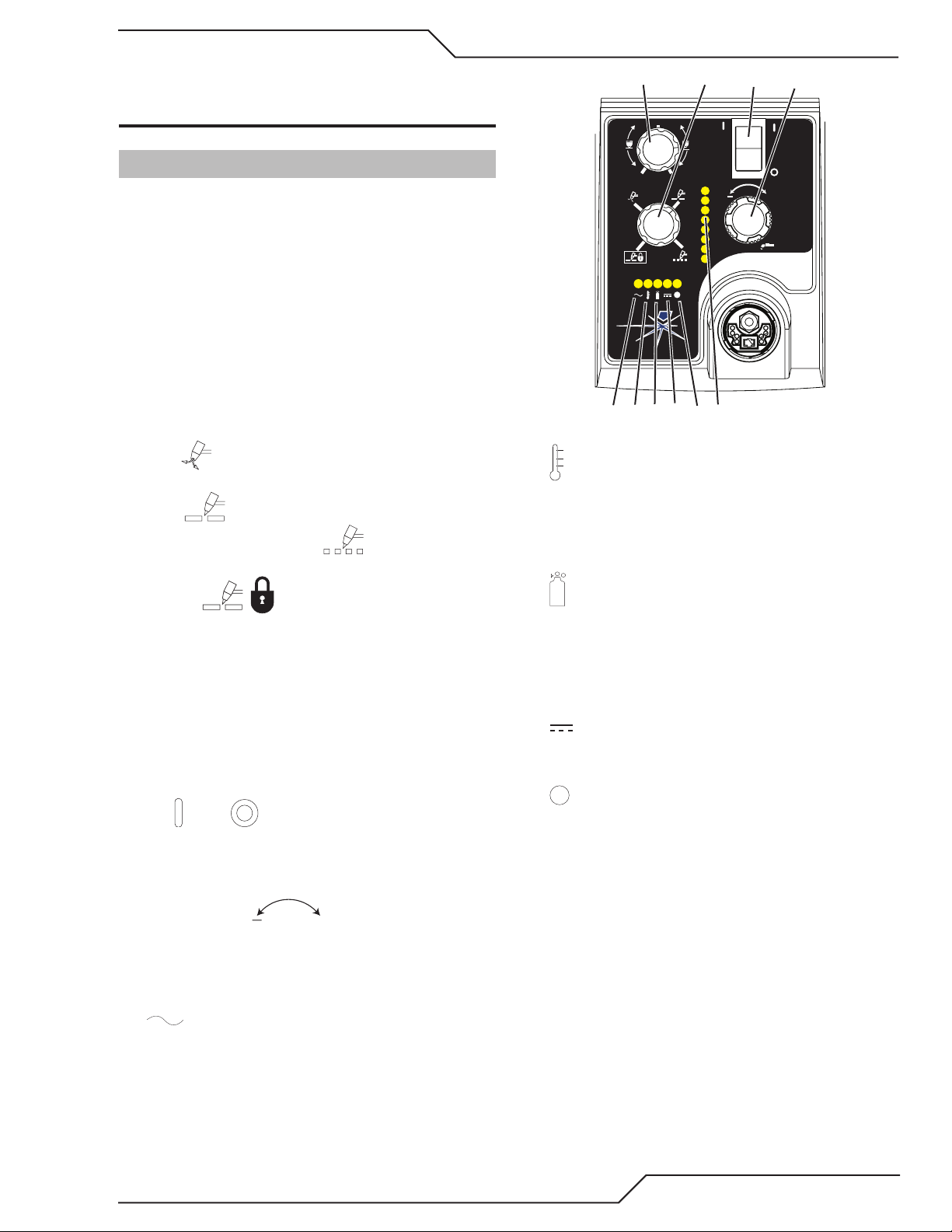
4.01 Front Panel Controls / Features
See Illustration for numbering Identification
1. Output Current Control
Sets the desired output current. Output settings
up to 60 Amps may be used for drag cutting (with
the torch tip contacting the workpiece) or higher for
standoff cutting.
2. Function Control
Function Control Knob, Used to select between the
different operating modes.
SET Used to purge the air through the unit
and torch and leads and to adjust gas pressure.
RUN Used for general cutting operations
RAPID AUTO RESTART Allows for faster
restarting of the Pilot Arc for uninterrupted cutting.
4
MAX
MIN
A
PSI BAR
MAXMAX
MINMIN
!
+
Art# A-07886
8
6. Temp Indicator
Indicator is normally OFF. Indicator is ON when
internal temperature exceeds normal limits. Let the
unit cool before continuing operation.
LATCH Used for longer hand held or
mechanical cuts. (Does not apply to automation).
Once a cutting arc is established, the torch switch
can be released. The cutting arc will remain ON
until the torch is lifted away from the work piece,
the torch leaves the edge of the work piece the
torch switch is activated again or if one of the system interlocks is activated.
3. ON OFF Power Switch
ON / OFF Switch controls input power to the
power supply. Up is ON, down is OFF.
4. Air/Gas Pressure Control
The Pressure
"SET" mode to adjust the air/gas pressure. Pull the
knob out to adjust and push in to lock.
5. AC Indicator
Steady light indicates power supply is ready for operation. Blinking light indicates unit is in protective
interlock mode. Shut unit OFF, shut OFF or disconnect input power, correct the fault, and restart the
unit. Refer to Section 5 for details.
7. Gas Indicator
Indicator is ON when minimum input gas pressure
for power supply operation is present. Minimum
pressure for power supply operation is not sufcient
for torch operation.
8. DC Indicator
Indicator is ON when DC output circuit is active.
9. ! Fault Error Indicator
Indicator is ON when Fault circuit is active. See sec-
tion 5 for explanations of fault lights.
Control is used in the
0-5430 OPERATION
4-1

CUTMASTER A120
Art # A-08170
Art # A-04509
10. Pressure Indicators
PSI BAR
MAX MAX
90 6.3
85 5.9
80
5.5
75
5.2
70
4.8
65
4.5
MINMIN
The Indicators will illuminate according to the pres-
sure set by the Pressure Control Knob (number 4).
4.02 Preparations for Operation
At the start of each operating session:
WARNING
Disconnect primary power at the source
before assembling or disassembling
power supply, torch parts, or torch and
leads assemblies.
Torch Parts Selection
Check the torch for proper assembly and appropriate
torch parts. The torch parts must correspond with
the type of operation, and with the amperage output
of this Power Supply (120 amps maximum). Refer to
Section 4T.07 and following for torch parts selection.
Torch Connection
Check that the torch is properly connected. Only
ESAB model SL100 / Manual or SL100 / Mechanical Torches may be connected to this Power Supply.
See Section 3T of this manual.
Check Primary Input Power Source
1. Check the power source for proper input voltage. Make sure the input power source meets
the power requirements for the unit per Section
2, Specications.
2. Connect the input power cable (or close the main
disconnect switch) to supply power to the system.
Connect Work Cable
Clamp the work cable to the workpiece or cutting
table. The area must be free from oil, paint and rust.
Connect only to the main part of the workpiece; do
not connect to the part to be cut off.
Power ON
Place the Power Supply ON / OFF switch to the ON
(up) position. AC indicator turns ON. Gas
indicator turns ON if there is sufcient gas pressure for power supply operation and the cooling
fans turn ON.
NOTE!
Minimum pressure for power supply operation is lower than minimum for torch
operation.
The cooling fans will turn ON as soon
as the unit is turned ON. After the unit
is idle for ten (10) minutes the fans will
turn OFF. The fans will come back ON
as soon as the torch switch (Start Signal) is activated or if the unit is turned
OFF, then turned ON again. If an over
temperature condition occurs, the fans
will continue to run while the condition
exists and for a ten (10) minute period
once the condition is cleared.
Set Operating Pressure
1. Place the Power Supply Function Control knob
to the SET position. Gas will ow.
2. For Standoff cutting, adjust gas pressure from 70
- 85 psi / 4.8 - 5.9 bar (LED's in center of control
panel). Refer to the Standoff chart for pressure
setting details.
Air Source
Ensure source meets requirements (refer to Section
2). Check connections and turn air supply ON.
OPERATION 0-5430
4-2
 Loading...