

Page 1

ESAB Cutmaster® 40
PLASMA CUTTING SYSTEM
SL60 1Torch™
Operating
Manual
Art # A-12777_AA
40
Révision : AB Issue Date: July 31, 2015 Manual No.: 0-5376
120V
esab.com.br
230V
Page 2

WE APPRECIATE YOUR BUSINESS!
Congratulations on your new ESAB product. We are proud to have you as our customer and will strive to
provide you with the best service and reliability in the industry. This product is backed by our extensive
warranty and world-wide service network. To locate your nearest distributor or service agency, visit us on
the web at www.esab.com.br.
This Operating Manual has been designed to instruct you on the correct use and operation of your ESAB
product. Your satisfaction with this product and its safe operation is our ultimate concern. Therefore please
take the time to read the entire manual, especially the Safety Precautions. They will help you to avoid potential
hazards that may exist when working with this product.
YOU ARE IN GOOD COMPANY!
The Brand of Choice for Contractors and Fabricators Worldwide.
ESAB is a Global Brand of manual and automation Plasma Cutting Products.
We distinguish ourselves from our competition through market-leading, dependable products that have stood
the test of time. We pride ourselves on technical innovation, competitive prices, excellent delivery, superior
customer service and technical support, together with excellence in sales and marketing expertise.
Above all, we are committed to developing technologically advanced products to achieve a safer working
environment within the welding industry.
Page 3

WARNING
!
Read and understand this entire Manual and your employer’s safety practices before installing, operating, or servicing the equipment.
While the information contained in this Manual represents the Manufacturer's best judgement,
the Manufacturer assumes no liability for its use.
Plasma Cutting Power Supply
ESAB Cutmaster 40
SL60 1Torch™
Operating Manual Number 0-5376
Published by:
ESAB Group Inc.
2800 Airport Road
Denton, TX 76207 U.S.A.
www.esab.com.br
Copyright 2015 by ESAB
All rights reserved.
Reproduction of this work, in whole or in part, without written permission of the
publisher is prohibited.
The publisher does not assume and hereby disclaims any liability to any party for
any loss or damage caused by any error or omission in this Manual, whether such
error results from negligence, accident, or any other cause.
Original Publication Date: January 15, 2015
Revision Date: July 31, 2015
Record the following information for Warranty purposes:
Where Purchased:_______________________________ __________
Purchase Date:__________________________________ __________
Power Supply Serial #:___________________________ __________
Torch Serial #:___________________________________ __________
i
Page 4

Be sure this information reaches the operator.
You can get extra copies through your supplier.
CAUTION
These INSTRUCTIONS are for experienced operators. If you are not fully familiar
with the principles of operation and safe practices for arc welding and cutting equipment, we urge you to read our booklet, “Precautions and Safe Practices for Arc
Welding, Cutting, and Gouging,” Form 52-529. Do NOT permit untrained persons to
install, operate, or maintain this equipment. Do NOT attempt to install or operate this
equipment until you have read and fully understand these instructions. If you do not
fully understand these instructions, contact your supplier for further information. Be
sure to read the Safety Precautions before installing or operating this equipment.
USER RESPONSIBILITY
This equipment will perform in conformity with the description thereof contained in this manual and accompanying
labels and/or inserts when installed, operated, maintained and repaired in accordance with the instructions provided.
This equipment must be checked periodically. Malfunctioning or poorly maintained equipment should not be used.
Parts that are broken, missing, worn, distorted or contaminated should be replaced immediately. Should such repair or
replacement become necessary, the manufacturer recommends that a telephone or written request for service advice
be made to the Authorized Distributor from whom it was purchased.
This equipment or any of its parts should not be altered without the prior written approval of the manufacturer. The
user of this equipment shall have the sole responsibility for any malfunction which results from improper use, faulty
maintenance, damage, improper repair or alteration by anyone other than the manufacturer or a service facility designated by the manufacturer.
!
READ AND UNDERSTAND THE INSTRUCTION MANUAL BEFORE INSTALLING OR
OPERATING.
PROTECT YOURSELF AND OTHERS!
Page 5

TABLE OF CONTENTS
SECTION 1: SAFETY..........................................................................................................................................1-1
1.0 Safety Precautions ..........................................................................................................1-1
SECTION 2 SYSTEM: INTRODUCTION ..............................................................................................................2-1
2.01 How To Use This Manual .................................................................................................2-1
2.02 Equipment Identification ..................................................................................................2-1
2.03 Receipt Of Equipment ......................................................................................................2-1
2.04 Working Principle ............................................................................................................2-2
2.05 Power Supply Specifications ...........................................................................................2-2
2.06 Input Wiring Specifications .............................................................................................. 2-3
2.07 Power Supply Features .................................................................................................... 2-4
SECTION 2 TORCH: INTRODUCTION ............................................................................................................... 2T-1
2T.01 Scope of Manual ........................................................................................................... 2T-1
2T.02 Specifications .............................................................................................................. 2T-1
2T.03 Introduction to Plasma .................................................................................................. 2T-2
SECTION 3: INSTALLATION ...............................................................................................................................3-1
3.01 Unpacking .......................................................................................................................3-1
3.02 Lifting Options .................................................................................................................3-1
3.03 Primary Input Power Connections ....................................................................................3-1
3.04 Air Supply Connections ...................................................................................................3-2
SECTION 4 SYSTEM: OPERATION ....................................................................................................................4-1
4.01 Control Panel ...................................................................................................................4-1
4.02 Preparations For Operating ..............................................................................................4-2
4.03 Sequence of Operation ....................................................................................................4-5
4.04 Cut Quality ......................................................................................................................4-7
4.05 General Cutting Information .............................................................................................4-7
SECTION 5 SYSTEM: SERVICE ..........................................................................................................................5-1
5.01 General Maintenance ......................................................................................................5-1
5.02 Basic Troubleshooting Guide ............................................................................................5-2
SERVICE .......................................................................................................................... 5T-1
SECTION 5 TORCH:
SECTION 6: PARTS LISTS .................................................................................................................................6-1
APPENDIX 1: ESAB CUTMASTER 40 CIRCUIT DIAGRAM ................................................................................ A-1
5T.01 General Maintenance .................................................................................................... 5T-1
5T.02 Inspection and Replacement of Consumable Torch Parts ...............................................5T-1
6.01 Introduction .....................................................................................................................6-1
6.02 Power Supply Replacement Parts ....................................................................................6-2
6.03 SL60 Torch Consumable Parts .........................................................................................6-3
6.04 Optional Accessories .......................................................................................................6-4
APPENDIX 2: SL60 TORCH PIN-OUT DIAGRAM ............................................................................................... A-2
Revision History .............................................................................................................................................. A-3
Page 6

This Page Intentionally Blank
Page 7

ESAB CUTMASTER 40
SECTION 1: SAFETY
1.0 Safety Precautions
Users of ESAB welding and plasma cutting equipment have the ultimate responsibility for ensuring that anyone who works
on or near the equipment observes all the relevant safety precautions. Safety precautions must meet the requirements that
apply to this type of welding or plasma cutting equipment. The following recommendations should be observed in addition
to the standard regulations that apply to the workplace.
All work must be carried out by trained personnel well acquainted with the operation of the welding or plasma cutting
equipment. Incorrect operation of the equipment may lead to hazardous situations which can result in injury to the operator
and damage to the equipment.
1. Anyone who uses welding or plasma cutting equipment must be familiar with:
- its operation
- location of emergency stops
- its function
- relevant safety precautions
- welding and / or plasma cutting
2. The operator must ensure that:
- no unauthorized person stationed within the working area of the equipment when it is started up.
- no one is unprotected when the arc is struck.
3. The workplace must:
- be suitable for the purpose
- be free from drafts
4. Personal safety equipment:
- Always wear recommended personal safety equipment, such as safety glasses, flame proof
clothing, safety gloves.
- Do not wear loose fitting items, such as scarves, bracelets, rings, etc., which could become
trapped or cause burns.
5. General precautions:
- Make sure the return cable is connected securely.
- Work on high voltage equipment may only be carried out by a qualified electrician.
- Appropriate fire extinguishing equipment must be clearly marked and close at hand.
- Lubrication and maintenance must not be carried out on the equipment during operation.
Dispose of electronic equipment at the recycling facility!
In observance of European Directive 2002/96/EC on Waste Electrical and Electronic Equipment and its
implementation in accordance with national law, electrical and/or electronic equipment that has reached the
end of its life must be disposed of at a recycling facility.
As the person responsible for the equipment, it is your responsibility to obtain information on approved collection stations.
For further information contact the nearest ESAB dealer.
ESAB can provide you with all necessary cutting protection and accessories.
Manual 0-5376 GENERAL INFORMATION
1-1
Page 8

ESAB CUTMASTER 40
WARNING
ELECTRIC SHOCK - Can kill.
- Install and earth (ground) the welding or plasma cutting unit in accordance with
applicable standards.
- Do not touch live electrical parts or electrodes with bare skin, wet gloves or wet clothing.
- Insulate yourself from earth and the workpiece.
- Ensure your working stance is safe.
FUMES AND GASES - Can be dangerous to health.
- Keep your head out of the fumes.
- Use ventilation, extraction at the arc, or both, to take fumes and gases away from your
breathing zone and the general area.
ARC R AYS - Can injure eyes and burn skin.
- Protect your eyes and body. Use the correct welding / plasma cutting screen and filter
lens and wear protective clothing.
- Protect bystanders with suitable screens or curtains.
FIRE HAZARD
- Sparks (spatter) can cause fire. Make sure therefore that there are no inflammable
materials nearby.
Arc welding and cutting can be injurious to yourself and others. Take
precautions when welding and cutting. Ask for your employer's safety
practices which should be based on manufacturers' hazard data.
NOISE - Excessive noise can damage hearing.
- Protect your ears. Use earmuffs or other hearing protection.
- Warn bystanders of the risk.
MALFUNCTION - Call for expert assistance in the event of malfunction.
READ AND UNDERSTAND THE INSTRUCTION MANUAL BEFORE INSTALLING OR OPERATING.
PROTECT YOURSELF AND OTHERS!
Do not use the power source for thawing frozen pipes.
WARNING
CAUTION
CAUTION
CAUTION
Class A equipment is not intended for use in residential locations
where the electrical power is provided by the public low-voltage
supply system. There may be potential difficulties in ensuring
electromagnetic compatibility of class A equipment in those locations, due to conducted as well as radiated disturbances.
This product is solely intended for metal removal. Any other use may
result in personal injury and / or equipment damage.
Read and understand the instruction manual before
installing or operating.
!
1-2
GENERAL INFORMATION Manual 0-5376
Page 9

ESAB CUTMASTER 40
!
SECTION 2 SYSTEM:
INTRODUCTION
2.01 How To Use This Manual
This Owner’s Manual applies to just specification or part numbers
listed on page i.
To ensure safe operation, read the entire manual, including the
chapter on safety instructions and warnings.
Throughout this manual, the words WARNING, CAUTION, DANGER,
and NOTE may appear. Pay particular attention to the information
provided under these headings. These special annotations are
easily recognized as follows:
NOTE!
An operation, procedure, or background
information which requires additional
emphasis or is helpful in efficient operation
of the system.
CAUTION
!
A procedure which, if not properly followed,
may cause damage to the equipment.
2.02 Equipment Identification
The unit’s identification number (specification or part number),
model, and serial number usually appear on a data tag attached
to the rear panel. Equipment which does not have a data tag
such as torch and cable assemblies are identified only by the
specification or part number printed on loosely attached card or
the shipping container. Record these numbers on the bottom of
page i for future reference.
2.03 Receipt Of Equipment
When you receive the equipment, check it against the invoice to
make sure it is complete and inspect the equipment for possible damage due to shipping. If there is any damage, notify the
carrier immediately to file a claim. Furnish complete information
concerning damage claims or shipping errors to the location in
your area listed in the inside back cover of this manual.
Include all equipment identification numbers as described above
along with a full description of the parts in error.
Move the equipment to the installation site before un-crating
the unit. Use care to avoid damaging the equipment when using
bars, hammers, etc., to un-crate the unit.
WARNING
A procedure which, if not properly followed,
may cause injury to the operator or others
in the operating area.
WARNING
Gives information regarding possible electrical shock injury. Warnings will be enclosed
in a box such as this.
DANGER
Means immediate hazards which, if not
!
Additional copies of this manual may be purchased by contacting
ESAB at the address and phone number in your area listed on
back cover of this manual. Include the Owner’s Manual number
and equipment identification numbers.
Electronic copies of this manual can also be downloaded at no
charge in Acrobat PDF format by going to the ESAB web site
listed below
http://www.esab.com.br
avoided, will result in immediate, serious
personal injury or loss of life.
Manual 0-5376 2-1 INTRODUCTION
Page 10
ESAB CUTMASTER 40
Art # A-09204_AB
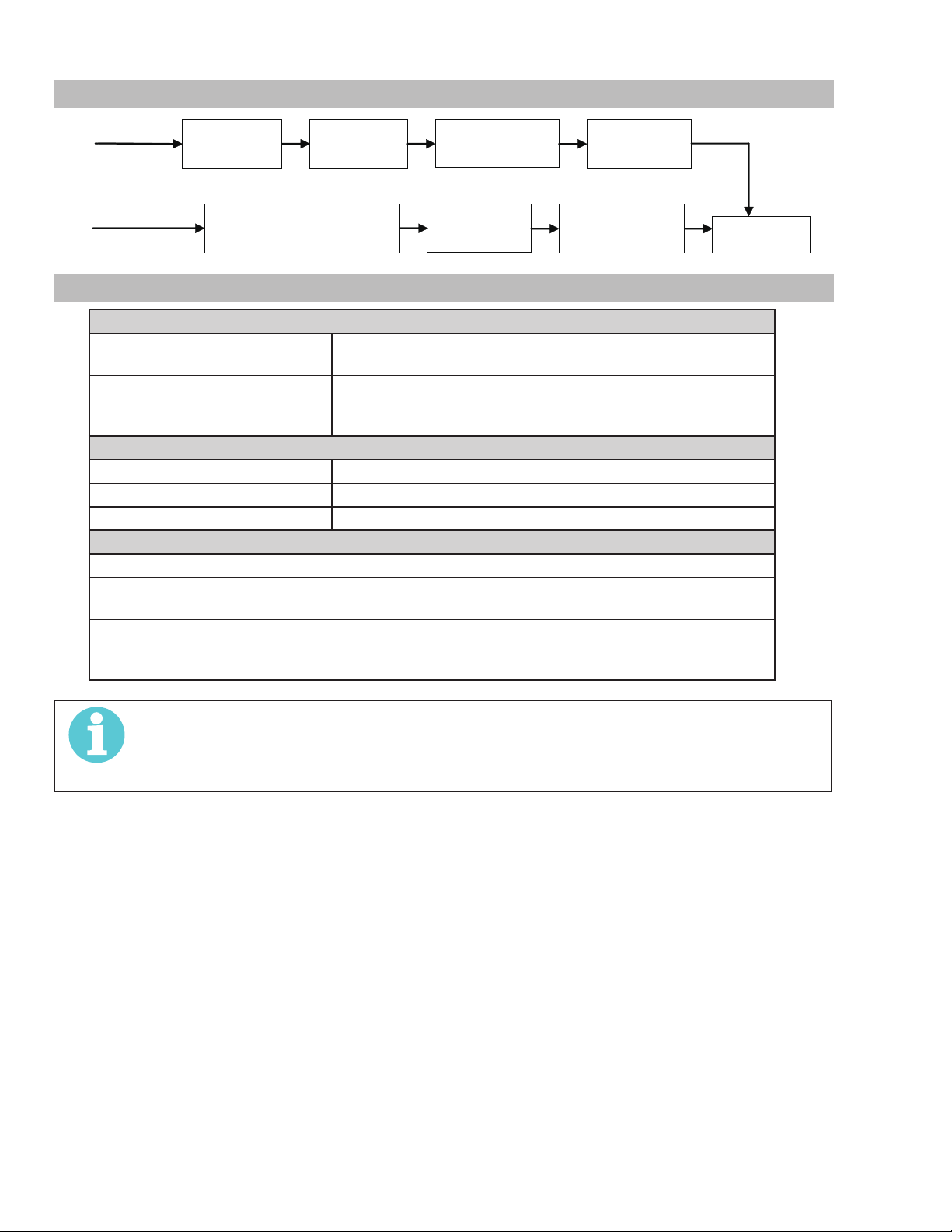
2.04 Working Principle
Transformer
Gas valve Cutting torch
Rectifier
Compressed air
Rectifier
Inverter
Reduce pressure, filter
2.05 Power Supply Specifications
ESAB Cutmaster 40 Power Supply Specifications
Input Power 120 VAC (+-10%), 1 Phase, 50/60Hz
230 VAC (+-10%), 1 Phase, 50/60Hz
Output Current 20 Amps @ 120VAC, 15A
20-27 Amps @ 120VAC, 20A
20-40 Amps @ 230VAC, 20A
ESAB Cutmaster 40 Power Supply Duty Cycle (Note 1)
Ambient Temperature 104° F (40° C)
Duty Cycle 30% @ 120VAC, 40% @ 230VAC
Rated Current 27 Amps @ 120VAC, 40 Amps @ 230V
SL60 1Torch Gas Requirements (see section 2T.03)
Notes
1. Duty Cycle is the percentage of time the system can be operated without overheating. Duty cycle is reduced if
primary input voltage (AC) is low or the DC voltage is higher than shown in this chart.
2. Air supply must be free of oil, moisture, and other contaminants. Excessive oil and moisture may cause doublearcing, rapid tip wear, or even complete torch failure. Contaminants may cause poor cutting performance and rapid
electrode wear. Optional filters provide increased filtering capabilities.
NOTE!
IEC Rating is determined as specified by the International Electro-Technical Commission. These specifications
include calculating an output voltage based upon power supply rated current. To facilitate comparison between
power supplies, all manufacturers use this output voltage to determine duty cycle.
Workpiece
INTRODUCTION 2-2 Manual 0-5376
Page 11

26lb / 11.8kg
9" (228.6mm)
120V 15A
120V 20A
230V 20A
30
24
20
27
20
40
A
18.5" (469.9mm)
Art# A-12781_AA
7" (177mm)
Figure 2-1: Power Supply Dimensions & Weight
ESAB CUTMASTER 40
NOTE!
Weight includes torch & leads, input power cord, and work cable with clamp.
CAUTION
!
Provide clearance for proper air flow through the power supply. Operation without proper air flow will
inhibit proper cooling and reduce duty cycle.
2.06 Input Wiring Specifications
ESAB Cutmaster 40 Input Power Requirements
Input Power Input Current Input Current Input Suggested Sizes (See Note)
Voltage Freq. (kVA) Max (Amps) Ieff (Amps) Fuse (Amps)
(Volts-AC) (Hz) 1-Ph 1-Ph 1-Ph 1-Ph
120 50/60 3.3 27.5 15 25
230 50/60 5.0 21.4 13.5 20
Line Voltages with Suggested Circuit Protection
Motor start fuses or thermal circuit breakers are recommended for this application. Check local requirements for your situation in this
regard.
NOTE!
Refer to Local and National Codes or local authority having jurisdiction for proper wiring requirements.
Cable size is de-rated based on the Duty Cycle of the equipment.
The suggested sizes are based on flexible power cable with power plug installations.
Cable conductor temperature used is
167° F (75° C).
Manual 0-5376 2-3 INTRODUCTION
Page 12

ESAB CUTMASTER 40
To
ce
Art# A-09335
2.07 Power Supply Features
rch Lead
120/230 VAC Power Sour
Air Inlet
Control Panel
120V 15A
120V 20A
230V 20A
30
24
20
27
20
40
A
Art # A-12779_AA
Work Cable and Clamp
On/Off
Switch
Air Inlet
Power Cord
INTRODUCTION 2-4 Manual 0-5376
Page 13

ESAB CUTMASTER 40
(95 mm)
!
SECTION 2 TORCH:
INTRODUCTION
2T.01 Scope of Manual
This manual contains descriptions, operating instructions and maintenance procedures for the SL60 Plasma Cutting Torch. Service of
this equipment is restricted to properly trained personnel; unqualified personnel are strictly cautioned against attempting repairs or
adjustments not covered in this manual, at the risk of voiding the
Warranty. Read this manual thoroughly. A complete understanding
of the characteristics and capabilities of this equipment will assure
the dependable operation for which it was designed.
2T.02 Specifications
A. Torch Configurations
1. Hand Torch, Model SL60
The hand torch head is at 75° to the torch handle. The hand
torches include a torch handle and torch trigger assembly.
10.125" (257 mm)
F. Torch Ratings
SL60 Torch Ratings
Ambient
Temperature
Duty Cycle 100% @ 60 Amps @ 400 scfh
Maximum Current 60 Amps
Voltage (V
Arc Striking Voltage
Torch Control Circuit
Voltage
G. Current Ratings
SL60 Torch & Leads
) 500V
peak
SL60 Current Ratings
Up to 60 Amps, DC,
Straight Polarity
NOTE!
Power Supply characteristics will determine
material thickness range.
H. Gas Requirements
104° F
40° C
7kV
24V
3.75"
Art # A-03322_AB
1.17" (29 mm)
B. Torch Leads Lengths
Hand Torches are available as follows:
• 20 ft / 6.1 m, with ATC connectors
C. Torch Parts (see Section 6.03)
Starter Cartridge, Electrode, Tip, Shield Cup
D. Parts - In - Place (PIP)
Torch has built-in switch.
12 vdc circuit rating
E. Type Cooling
Combination of ambient air and gas stream through torch.
SL60 Torch Gas Specifications
Gas (Plasma and Secondary) Compressed Air
Minimum Input Pressure
Maximum Input Pressure 125 psi / 8.6 bar
Gas Flow
60 - 95 psi
4.1 - 6.5 bar
300 - 500 scfh
142 - 235 lpm
WARNING
This torch is not to be used with oxygen (O2)
This torch is not to be used with high frequency starting systems.
Manual 0-5376 2T-1 INTRODUCTION
Page 14

ESAB CUTMASTER 40
C
A-02997
r
2T.03 Introduction to Plasma
A. Plasma Gas Flow
Plasma is a gas which has been heated to an extremely high
temperature and ionized so that it becomes electrically conductive. The plasma arc cutting and gouging processes use
this plasma to transfer an electrical arc to the workpiece. The
metal to be cut or removed is melted by the heat of the arc and
then blown away.
While the goal of plasma arc cutting is separation of the material,
plasma arc gouging is used to remove metals to a controlled
depth and width.
In a Plasma Cutting Torch a cool gas enters Zone B, where a
arc between the electrode and the torch tip heats and ionizes
the gas. The main cutting arc then transfers to the workpiece
through the column of plasma gas in Zone C.
By forcing the plasma gas and electric arc through a small orifice,
the torch delivers a high concentration of heat to a small area.
The stiff, constricted plasma arc is shown in Zone C. Direct
current (DC) straight polarity is used for plasma cutting, as
shown in the illustration.
Zone A channels a secondary gas that cools the torch. This gas
also assists the high velocity plasma gas in blowing the molten
metal out of the cut allowing for a fast, slag - free cut.
B. Gas Distribution
The single gas used is internally split into plasma and secondary gases.
The plasma gas flows into the torch through the negative lead,
through the starter cartridge, around the electrode, and out
through the tip orifice.
The secondary gas flows down around the outside of the torch
starter cartridge, and out between the tip and shield cup around
the plasma arc.
C. Pilot Arc
When the torch is started a pilot arc is established between
the electrode and cutting tip. This pilot arc creates a path for
the main arc to transfer to the work.
D. Main Cutting Arc
DC power is also used for the main cutting arc. The negative
output is connected to the torch electrode through the torch
lead. The positive output is connected to the workpiece via
the work cable and to the torch through a pilot wire.
E. Parts - In - Place (PIP)
The torch includes a 'Parts - In - Place' (PIP) circuit. When the
shield cup is properly installed, it closes a switch. The torch
will not operate if this switch is open.
_
Power
Supply
+
Workpiece
Typical Torch Head Detail
A-00002
B
A
To Control
Torch Switch
Cable Wiring
PIP Switch
Torch Trigge
Shield Cup
Parts - In - Place Circuit Diagram for Hand Torch
INTRODUCTION 2T-2 Manual 0-5376
Page 15

SECTION 3: INSTALLATION
!
3.01 Unpacking
1. Use the packing lists to identify and account for each item.
2. Inspect each item for possible shipping damage. If damage
is evident, contact your distributor and / or shipping company
before proceeding with the installation.
3. Record Power Supply and Torch model and serial numbers,
purchase date and vendor name, in the information block at
the front of this manual.
3.02 Lifting Options
The Power Supply includes a handle for hand lifting only. Be
sure unit is lifted and transported safely and securely.
WARNING
Do not touch live electrical parts.
Disconnect input power cord before moving
unit.
ESAB CUTMASTER 40
Art# A-09432_AB
Figure 3-1: 120VAC Adapter Pigtail
CAUTION
!
Check your power source for correct voltage before plugging in or connecting the
unit. The primary power source, fuse, and
any extension cords used must conform to
local electrical code and the recommended
circuit protection and wiring requirements
as specified in Section 2.
WARNING
FALLING EQUIPMENT can cause serious
personal injury and can damage equipment.
HANDLE is not for mechanical lifting.
• Only persons of adequate physical strength should
lift the unit.
• Lift unit by the handle, using two hands. Do not
use straps for lifting.
• Use optional cart or similar device of adequate
capacity to move unit.
• Place unit on a proper skid and secure in place
before transporting with a fork lift or other vehicle.
3.03 Primary Input Power Connections
Power Cords Included With Power Supply
Attached to the power supply is an input power cord with a 230
Volt 50 Amp NEMA 6-50P for plug. Optional adapters allow for
connection of the power supply input cable plug when using 120V
input power.
Input Volt-
age (VAC)
120V, 15A
Circuit
120V, 20A
Circuit
120V, 30A
Circuit
208-230V,
20A Circuit
Rated
Output
20A, 88V
27A, 91V
27A, 91V
40A, 96V
Amps (RMS) input at
rated output, 60 Hz,
single-phase
20.4 2.5
28.5 3.5
28.5 3.5
23-21.4 4.8
kVA
Manual 0-5376 3-1 INSTALLATION
Page 16

ESAB CUTMASTER 40
Art# A-09337
On/Off
3.04 Air Supply Connections
A. Connecting Air Supply to Unit
The connection is the same for compressed air or industrial compressed air in gas cylinders.
1. Connect the gas line to the compressed air inlet port at the appropriate pressure. Air inlet port is an ISO7/1 tapered fitting. A ¼
NPT adapter is included with the machine.
Switch
Air Inlet
Figure 3-2: Gas Connection to Compressed Air input
B. Using Industrial Compressed Air In Gas Cylinders
When using Industrial compressed air in gas cylinders as the gas supply:
1. Refer to the manufacturer’s specifications for installation and maintenance procedures for high pressure gas regulators.
2. Examine the cylinder valves to be sure they are clean and free of oil, grease or any foreign material. Briefly open each cylinder
valve to blow out any dust which may be present.
3. The cylinder must be equipped with an adjustable high - pressure regulator capable of outlet pressures up to 100 psi (6.9 bar)
maximum and flows of at least 250 scfh (120 lpm).
4. Connect gas supply hose to the cylinder.
NOTE!
Pressure should be set at 100 psi (6.9 bar) at the high pressure cylinder regulator.
Supply hose must be at least 1/4 inch (6 mm) I.D.
For a secure seal, apply thread sealant to the fitting threads, according to manufacturer's instructions. Do
Not use Teflon tape as a thread sealer, as small particles of the tape may break off and block the small air
passages in the torch.
INSTALLATION 3-2 Manual 0-5376
Page 17

4.01 Control Panel
The Front Panel The Rear Panel
ESAB CUTMASTER 40
SECTION 4 SYSTEM: OPERATION
AC Indicator
120V 15A
120V 20A
230V 20A
30
24
20
27
20
40
DC Indicator (Ready)
Air Indicator
Overheat Indicator
A
Power Cord
On/Off
Switch
Air Inlet
Art# A-12788
1. ON / OFF Switch (Power Switch/Lamp)
Controls input power to the power supply. I is ON (Red Lamp), O is OFF.
2. (A) Output Current Control
Sets the desired output current. If the overload protection (fuse or circuit breaker) on the input power circuit opens frequently,
either reduce cutting output, reduce the cutting time, or connect the unit to more adequate input power. Note: For 120V input
power, the unit will automatically limit the output current to a maximum of 27A. For 230V input power, the maximum output is 40
Amps. Refer to Section 2 for input power requirements.
3. AC Indicator
Steady light indicates power supply is ready for operation.
4. OVERHEAT Indicator (TEMP Indicator)
Indicator is normally OFF. Indicator is ON when internal temperature exceeds normal limits. Allow the unit to run with the fan on
until the temp indicator turns OFF.
5. AIR Indicator
AIR light should be ON when there is sufficient gas pressure.
6. READY (DC Indicator)
Indicator is ON when DC output circuit is active.
NOTE!
All consumables must be correctly installed and maintained to ensure correct operation.
Manual 0-5376 4-1 OPERATION
Page 18

ESAB CUTMASTER 40
4.02 Preparations For Operating
At the start of each operating session:
WARNING
Disconnect primary power at the source before assembling or disassembling power supply, torch parts, or
torch and leads assemblies.
A. Torch Parts Selection
Check the torch for proper assembly and appropriate torch parts. The torch parts must correspond with the type of operation, and
with the amperage output of this power supply (60 amps maximum). Use only genuine ESAB parts with this torch.
Start
Cartridge
9-8213
Electrode
9-8215
Art # A-12890
Tips:
DRAG TIP
CUTTING
20A 9-8205
30A 9-8206
40A 9-8207
DRAG SHIELD
CUTTING
40A
CUTTING
Tip:
40A 9-8208
STANDOFF
CUTTING
40-120A
GOUGING
Tips:
Tip Gouging A 9-8225 (40 Amps Max.)
Shield
Cup Body,
9-8237
Shield Cup
9-8218
O-Ring No. 8-3488
Shield
Cup Body,
9-8237
Shield Cup
9-8218
Shield
Cup Body,
9-8237
Shield Cap, Deflector
9-8243
Shield Cap, Drag
40A 9-8244
Shield Cap, Deflector
9-8243
Standoff Guide
9-8251
Shield Cap, Gouging
9-8241
NOTE
ESAB CutMaster 60 uses 60A and less
ESAB CutMaster 80 uses 80A and less
ESAB CutMaster 100 uses 100A and less
ESAB CutMaster 120 uses 120A and less
OPERATION 4-2 Manual 0-5376
Page 19

ESAB CUTMASTER 40
Art # A-03387
Art# A-09335
A
Art# A-09339_AD
NOTE!
When operating the torch in a normal condition, some gas vents through the gap between the shield
cup and torch handle. Do not attempt to over tighten the shield cup as irreparable damage to internal
components may result.
B. Torch Connection
Check that the torch is properly connected.
C. Check Primary Input Power Source
1. Check the power source for proper input voltage. Make sure the input power source meets the power requirements for the unit
per Section 2, Specifications.
2. Connect the input power cable (or close the main disconnect switch) to supply power to the system.
D. Gas Selection
Ensure gas source meets requirements listed in section 2T. Check connections and turn gas supply on.
E. Connect Work Cable
Clamp the work cable to the workpiece or cutting table. The area must be free from oil, paint and rust. Connect only to the main
part of the workpiece; do not connect to the part to be cut off.
F. Power On
Place the power supply ON / OFF switch to the ON (I) position. Power indicator turns on.
On/Off
Switch
Power Cord
Air Inlet
20
20
Rear Panel with ON/OFF Switch Front Panel With Power ON/OFF Indicator
120V 15A
120V 20A
230V 20A
30
24
27
40
Manual 0-5376 4-3 OPERATION
Page 20

ESAB CUTMASTER 40
120V
2
A
40
40
4
0
A#09697_AA
G. Select Current Output Level
Set the desired current output level.
120V 15A
120V 20A
230V 20A
30
24
20
20
, 15A
30
24
20
20
4
27
40
A
20
20
120V, 20A
3
30
24
27
40
27
40
A
A
20
20
230V, 20A
30
24
27
40
A
OPERATION 4-4 Manual 0-5376
Page 21

ESAB CUTMASTER 40
A-00024_AB
Shield Cup
Torch
Standoff Distance
1/8" - 3/8" (3 - 9mm)
t # A-03383
Tr igger
4.03 Sequence of Operation
The following is a typical sequence of operation for this power
supply.
1. Place the ON / OFF switch on the power supply to ON
(up) position (Red indicator lamp is illuminated).
a. AC indicator turns on; fan turns on.
NOTE!
During initial power up, there will be a delay
of about 2 seconds before the AC Indicator light will illuminate and the pre-flow
gas and fan starts. The gas will automatically flow from torch for approximately 10
seconds (only after the AC Indicator lamp is
illuminated) (The AC Indicator lamp and fan
turns on approximately 2 seconds after the
ON/OFF switch is enabled), this is a process
that makes sure all inputs (gas, input
power, torch connection, and torch parts)
are acknowledged for proper operation.
2. Wear protective clothing, including welding gloves and
appropriate eye protection (see table 1-1). Place tip on
work piece and pull trigger. Arc will initiate and start cutting
material.
Standoff Cutting With Hand Torch
b) For standoff cutting, hold the torch tip on the
work piece, pull the trigger. After the arc is
initiated lift the tip to 1/8" - 3/8" (3-4mm) off
the work.
Standoff Distance
Trigger
NOTE!
For best performance and parts life, always
use the correct parts for the type of operation.
A. The torch can be comfortably held in one hand or
steadied with two hands. Position the hand to press
the Trigger on the torch handle. With the hand torch,
the hand may be positioned close to the torch head for
maximum control or near the back end for maximum
heat protection. Choose the holding technique that
feels most comfortable and allows good control and
movement.
NOTE!
The tip should never come in contact with
the workpiece except during drag cutting
operations.
B. Depending on the cutting operation, do one of the
following:
a) For drag cutting, place the tip on the plate holding
the torch at a angle to the plate so that only one
edge of the tip is in contact with the plate. This
prevents damage to the tip during the piercing
process.
Trigger Release
A-02986
1
2
Tr igger Release
3
4
Ar
Manual 0-5376 4-5 OPERATION
Page 22

ESAB CUTMASTER 40
t # A-03383
Tr igger
NOTE!
When the shield cup is properly installed,
there is a slight gap between the shield cup
and the torch handle. Gas vents through
this gap as part of normal operation. Do
not attempt to force the shield cup to close
this gap. Forcing the shield cup against
the torch head or torch handle can damage
components.
Drag Cutting With a Hand Torch
Drag cutting works best on metal 1/4"(6 mm) thick or less.
NOTE!
For best performance and parts life, always
use the correct parts for the type of operation.
1
2
Tr igger Release
3
4
Ar
A. Install the drag cutting tip and set the output current.
B. The torch can be comfortably held in one hand or
steadied with two hands. Position the hand to press
the Trigger on the torch handle. With the hand torch,
the hand may be positioned close to the torch head for
maximum control or near the back end for maximum
heat protection. Choose the holding technique that
feels most comfortable and allows good control and
movement.
C. Keep the torch in contact with the workpiece during
the cutting cycle.
D. Hold the torch away from your body.
E. Slide the trigger release toward the back of the torch
handle while simultaneously squeezing the trigger.
The arc will start.
Trigger
G. Cut as usual. Simply release the trigger assembly to
stop cutting.
H. Follow normal recommended cutting practices as
provided herein.
3. Complete cutting operation.
NOTE!
If the torch is lifted too far from the workpiece while cutting, the main arc will stop
and the pilot arc will automatically restart.
4. Release the torch trigger.
a. Main arc stops.
5. Set the power supply ON / OFF switch to OFF (down position).
a. AC indicator turns OFF.
6. Set the main power disconnect to OFF, or unplug input
power cord.
a. Input power is removed from the system.
Trigger Release
A-02986
F. Place the torch tip on the work. The main arc will
transfer to the work.
NOTE!
The gas preflow and postflow are a characteristic of the power supply and not a
function of the torch.
OPERATION 4-6 Manual 0-5376
Page 23

ESAB CUTMASTER 40
Kerf Width
Drag Lines
!
4.04 Cut Quality
NOTE!
Cut quality depends heavily on setup and
parameters such as torch standoff, alignment with the workpiece, cutting speed,
gas pressures, and operator ability. Refer to
appendix pages for additional information
as related to the power supply.
Cut quality requirements differ depending on application. For
instance, nitride build-up and bevel angle may be major factors
when the surface will be welded after cutting. Dross-free cutting
is important when finish cut quality is desired to avoid a secondary
cleaning operation. The following cut quality characteristics are
illustrated in the following figure:
Cut Surface
Bevel Angle
Top
Spatter
Top Edge
Rounding
Dross
Build-Up
Cut Surface
A-00007
Kerf Width
The width of the cut (or the width of material removed during
the cut).
Top Spatter (Dross)
Top spatter or dross on the top of the cut caused by slow travel
speed, excess cutting height, or cutting tip whose orifice has
become elongated.
4.05 General Cutting Information
WARNING
Disconnect primary power at the source before disassembling the power supply, torch,
or torch leads.
Frequently review the Important Safety Precautions at the front of this manual. Be sure
the operator is equipped with proper gloves,
clothing, eye and ear protection. Make sure
no part of the operator’s body comes into
contact with the workpiece while the torch
is activated.
CAUTION
!
Sparks from the cutting process can cause
damage to coated, painted, and other surfaces such as glass, plastic and metal.
Cut Surface
The desired or specified condition (smooth or rough) of the
face of the cut.
Nitride Build - Up
Nitride deposits can be left on the surface of the cut when
nitrogen is present in the plasma gas stream. These buildups
may create difficulties if the material is to be welded after the
cutting process.
Bevel Angle
The angle between the surface of the cut edge and a plane
perpendicular to the surface of the plate. A perfectly perpendicular cut would result in a 0° bevel angle.
Top - Edge Rounding
Rounding on the top edge of a cut due to wearing from the
initial contact of the plasma arc on the workpiece.
Bottom Dross Buildup
Molten material which is not blown out of the cut area and
resolidifies on the plate. Excessive dross may require secondary cleanup operations after cutting.
Cut Quality Characteristics
NOTE!
Handle torch leads with care and protect
them from damage.
Torch Standoff
Improper standoff (the distance between the torch tip and
workpiece) can adversely affect tip life as well as shield cup
life. Standoff may also significantly affect the bevel angle.
Reducing standoff will generally result in a more square cut.
Edge Starting
For edge starts, hold the torch perpendicular to the workpiece
with the front of the tip near (not touching) the edge of the
workpiece at the point where the cut is to start. When starting
at the edge of the plate, do not pause at the edge and force the
arc to "reach" for the edge of the metal. Establish the cutting
arc as quickly as possible.
Manual 0-5376 4-7 OPERATION
Page 24

ESAB CUTMASTER 40
Left Side
A-00512
Direction of Cut
In the torches, the plasma gas stream swirls as it leaves the
torch to maintain a smooth column of gas. This swirl effect
results in one side of a cut being more square than the other.
Viewed along the direction of travel, the right side of the cut
is more square than the left.
Cut Angle
Right Side
Cut Angle
Side Characteristics Of Cut
To make a square - edged cut along an inside diameter of a
circle, the torch should move counterclockwise around the
circle. To keep the square edge along an outside diameter cut,
the torch should travel in a clockwise direction.
Dross
When dross is present on carbon steel, it is commonly referred
to as either “high speed, slow speed, or top dross”. Dross present on top of the plate is normally caused by too great a torch
to plate distance. "Top dross" is normally very easy to remove
and can often be wiped off with a welding glove. "Slow speed
dross" is normally present on the bottom edge of the plate.
It can vary from a light to heavy bead, but does not adhere
tightly to the cut edge, and can be easily scraped off. "High
speed dross" usually forms a narrow bead along the bottom
of the cut edge and is very difficult to remove. When cutting a
troublesome steel, it is sometimes useful to reduce the cutting
speed to produce "slow speed dross". Any resultant cleanup
can be accomplished by scraping, not grinding.
OPERATION 4-8 Manual 0-5376
Page 25

5.01 General Maintenance
Warning!
Art # A-12778_AA
There are extremely dangerous voltage and power levels present inside
this product. Do not attempt to open or repair unless you are a qualified
electrical tradesperson and you have had training in power measurements
and troubleshooting techniques. If major complex subassemblies are faulty,
then the Cutting Power Source must be returned to an Accredited Service
Provider for repair.
ESAB CUTMASTER 40
SECTION 5 SYSTEM: SERVICE
Maintain more often
if used under severe
conditions
Each Use
Visual check of
torch tip and electrode
Weekly
Visually inspect the torch body tip,
electrode, start cartridge and shield cup
Replace all
broken parts
Visually inspect the
cables and leads.
Replace as needed
3 Months
6 Months
Visually check and
Carefully clean the
interior
Clean
exterior
of power supply
30
A
20
40
CURRENT
30
A
20
40
CURRENT
Manual 0-5376 5-1 SERVICE
Page 26

ESAB CUTMASTER 40
A. Every three months
Check external air filter, replace if necessary.
1. Shut off input power; turn off the gas supply. Bleed down
the gas supply. Check air filter and replace if necessary.
NOTE!
Leave internal ground wire in place.
B. Every six months
1. Check the in-line air filter(s), clean or replace as required.
2. Check cables and hoses for leaks or cracks, replace if
necessary.
3. Check all contactor points for severe arcing or pits, replace
if necessary.
4. Vacuum dust and dirt out of the entire machine.
5.02 Basic Troubleshooting Guide
WARNING
There are extremely dangerous voltage and
power levels present inside this unit. Do
not attempt to diagnose or repair unless
you have had training in power electronics
measurement and troubleshooting techniques.
B. AC indicator blinking
1. Indicator blinking (1 sec ON/1 Sec OFF, Gas may also
pulse 3 times).
a. Check for missing torch parts or not properly
installed. Turn ON/OFF switch to OFF position and
restart the machine by turning the power switch to
ON.
2. Indicator blinking (1 sec ON/3 Sec OFF).
a. Check for worn or sticking torch parts. Replace if
necessary.
3. Indicator blinking (3 sec ON/3 Sec OFF).
a. Torch switch was depressed before machine was
completely powered up. Turn ON/OFF switch to OFF
position and the restart the machine by turning the
power switch to ON.
C. Air indicator OFF
1. Gas pressure too low. Check supply pressure.
D. TEMP indicator ON, (AC indicator ON)
1. Unit air flow obstructed.
a. Check for blocked air flow around the unit and correct
condition.
2. Fan blocked.
a. Check for blocked status and correct condition.
Common Faults symptom LED Indicators
A. AC indicator OFF
1. Main input power cord does not connect to power distribution net.
a. Connect the power cord.
2. Power ON/OFF switch in OFF (down) position.
a. Turn switch to ON (up) position.
3. Actual input voltage does not correspond to voltage of unit.
a. Verify that the input line voltage is correct.
4. Faulty components in unit
a. Return for repair or have qualified technician repair per
service manual.
3. Unit is overheated.
a. Keep the machine plugged in and turned on for five
minutes. This will allow the fan to run and cool the
machine.
4. Faulty components in unit
a. Return for repair or have qualified technician repair per
service manual.
SERVICE 5-2 Manual 0-5376
Page 27

E. Torch will not pilot, when torch trigger is activated.
1. Faulty parts in torch
a. Check torch parts per section 4.02 and 6.04; replace
as needed.
ESAB CUTMASTER 40
H. Output is restricted, and can not be controlled.
1. Input or output connection is poor.
a. Check all input and output connection leads.
2. Working cable connection to work piece is poor.
2. Gas pressure too low
a. Adjust supply pressure to proper setting value.
3. Faulty tip in use
a. In 115VAC operation, 40 Amp Tip is used which prevents
the unit from piloting;
Replace with 20 Amp Tip.
4. Faulty components in unit
a. Return for repair or have qualified technician repair per
service manual.
F. No cutting output when torch is activated; AC indicator
ON, gas flows, fan turns.
1. Torch is not connected properly to power supply.
a. Check torch connection to power supply.
2. Working cable not connected to work piece, or connection
is poor.
a. Make sure that work cable has a proper connection to
a clean, dry area of the work piece.
3. Faulty components in unit
a. Make sure that work cable has a proper connection to
a clean, dry area of the work piece.
3. Faulty components in unit
a. Return for repair or have qualified technician repair per
service manual.
I. Cutting output is unstable or inadequate at 120V opera-
tion.
1. Low or fluctuating input voltage
a. Turn output current to minimum (20 amps) and
suggest using 20A Drag tip.
b. Connect to a dedicated input line voltage.
c. Have electrician check input line voltage under load.
2. Input or output connection is poor
a. Check all input and output connection leads.
3. Working cable connection is poor.
a. Make sure that work cable has a proper connection to
a clean, dry area of the work piece.
J. Hard to startup
a. Return for repair or have qualified technician repair per
service manual.
4. Faulty torch
a. Return for repair or have qualified technician repair.
G. Torch cuts but not adequately
1. Incorrect setting of output current control
a. Check and adjust to proper setting.
2. Working cable connection to work piece is poor.
a. Make sure that work cable has a proper connection to
a clean, dry area of the work piece.
3. Faulty components in unit
a. Return for repair or have qualified technician repair.
1. Torch parts worn (consumables)
a. Turn off input power, remove shield cup, tip, start
cartridge, and electrode and check them all. If the
electrode or cutting tip is worn out, replace them. If
the start cartridge does not move freely, replace it. If
there is too much spatter on shield cup, replace it.
Manual 0-5376 5-3 SERVICE
Page 28

ESAB CUTMASTER 40
K. Arc goes out while operating. Arc can’t be restarted when torch trigger is activated.
1. Power Supply is overheated (TEMP indicator ON).
a. Let unit cool down for at least 5 minutes. Make sure the unit has not been operated beyond duty cycle limit.
2. Fan blades blocked (TEMP indicator ON).
a. Check and clear blades.
3. Air flow blocked
a. Check for blocked air flow around the unit and correct condition.
4. Gas pressure is too low. (Air indicator ON when torch trigger is activated.)
a. Check gas source. Adjust to proper setting value.
5. Torch parts worn
a. Check torch shield cup, cutting tip, start cartridge and electrode. Replace as needed.
6. Faulty component in unit
a. Return for repair or have qualified technician repair per service manual.
L. Torch cuts but not well.
1. Current control is set too low.
a. Increase the current setting.
2. Torch is being moved too fast across work piece
a. Reduce cutting speed.
3. Excessive oil or moisture in torch
a. Hold torch 1/8 inch (3 mm) from clean surface while purging and observe oil or moisture buildup (do not activate torch). If
there are contaminants in the gas, additional filtering may be needed.
4. Torch parts worn
a. Check torch shield cup, cutting tip, start cartridge and electrode. Replace as needed.
M. Gas in torch pulsates 3 times and then stops. AC indicator light blinking.
1. Torch parts not properly installed in torch. There may have been an attempt to remove torch parts without turning off ON/OFF
power switch to OFF on unit.
a. Check to make sure torch parts are properly installed.
b. Turn ON/OFF switch to OFF and then back to ON.
c. Check Start Cartridge to make sure the copper slider (or nozzle) moves in and out freely.
SERVICE 5-4 Manual 0-5376
Page 29

ESAB CUTMASTER 40
Art #A-03791_AB
A-03510_AB
SECTION 5 TORCH:
SERVICE
5T.01 General Maintenance
NOTE!
Refer to Previous "Section 5: System" for
common and fault indicator descriptions.
Cleaning Torch
Even if precautions are taken to use only clean air with a torch,
eventually the inside of the torch becomes coated with residue.
This buildup can affect the arc initiation and the overall cut
quality of the torch.
WARNING
Disconnect primary power to the system
before disassembling the torch or torch
leads.
DO NOT touch any internal torch parts
while the AC indicator light of the Power
Supply is ON.
The inside of the torch should be cleaned with electrical contact
cleaner using a cotton swab or soft wet rag. In severe cases,
the torch can be removed from the leads and cleaned more
thoroughly by pouring electrical contact cleaner into the torch
and blowing it through with compressed air.
5T.02 Inspection and Replacement of
Consumable Torch Parts
WARNING
Disconnect primary power to the system
Remove the consumable torch parts as follows:
1. Unscrew and remove the shield cup from the torch.
before disassembling the torch or torch
leads.
DO NOT touch any internal torch parts
while the AC indicator light of the Power
Supply is ON.
NOTE!
DO NOT use other lubricants or grease,
they may not be designed to operate
within high temperatures or may contain
“unknown elements” that may react with
the atmosphere. This reaction can leave
contaminants inside the torch. Either of
these conditions can lead to inconsistent
performance or poor parts life.
NOTE!
Slag built up on the shield cup that cannot
be removed may effect the performance of
the system.
!
CAUTION
Dry the torch thoroughly before reinstalling.
ATC Male Connector
Gas Fitting
O-Ring
2. Inspect the cup for damage. Wipe it clean or replace if
damaged.
Torch Head
Electrode
Start Cartridge
Tip
Shield Cup
Consumable Parts
Manual 0-5376 5T-1 SERVICE
Page 30

ESAB CUTMASTER 40
Good Tip
Worn Tip
A-03406
Art # A-08064_AC
Spring-Loaded
Spring-Loaded
/
Worn Electrode
New Electrode
Art # A-03284
3. Remove the tip. Check for excessive wear (indicated by an elongated or oversized orifice). Clean or replace the tip if necessary.
Tip Wear
4. Remove the starter cartridge. Check for excessive wear, plugged gas holes, or discoloration. Check the lower end fitting for
free motion. Replace if necessary.
Lower End Fitting
Full Compression
Lower End Fitting at Reset
Full Extension
5. Pull the electrode straight out of the torch head. Check the face of the electrode for excessive wear. Refer to the following
figure.
Electrode Wear
6. Reinstall the electrode by pushing it straight into the torch head until it clicks.
7. Reinstall the desired starter cartridge and tip into the torch head.
8. Hand tighten the shield cup until it is seated on the torch head. If resistance is felt when installing the cup, check the threads
before proceeding.
SERVICE 5T-2 Manual 0-5376
Page 31

ESAB CUTMASTER 40
SECTION 6: PARTS LISTS
6.01 Introduction
A. Parts List Breakdown
The parts list provides a breakdown of all replaceable components.
B. Returns
If a product must be returned for service, contact your distributor. Materials returned without proper authorization will not be accepted.
C. Ordering Information
Order replacement parts by catalog number and complete description of the part or assembly, as listed in the parts list for each type
item. Also include the model and serial number of the torch. Address all inquiries to your authorized distributor.
Manual 0-5376 6-1 PART LIST
Page 32

ESAB CUTMASTER 40
9
13
3
20
6.02 Power Supply Replacement Parts
Item # Qty. Description Catalog #
1 1 Control and Logic PCB assembly 9-0077
3 1 Main PCB assembly 9-0079
4 1 Regulator 9-0081
5 1 Solenoid assembly 9-0082
6 1 Pressure Switch 9-0075
7 1 Front Panel with Label 9-0071E
8 1 Rear Panel with Label 9-0072E
9 1 Cover with Labels 9-0080E
10 1 Hall Current Sensor 9-0088
11 1 Cutting Control Knob 9-0073
12 1 On/Off Switch 9-0074
13 1 ATC Connection 9-0083
14 1 Fan 9-0042
15 1 AC/DC Rectifier 9-0049
16 1 Power Cord 9-0025
17 1 Carry Case (not shown) 9-0084E
18 1 Gloves (not shown) 9-0086
19 1 Glasses (not shown) 9-0087
20 1 120VAC Adapter, 15A W4014000
16
12
8
Art # A-12889
15
14
4
6
10
5
1
11
7
PART LIST 6-2 Manual 0-5376
Page 33

6.03 SL60 Torch Consumable Parts
ESAB CUTMASTER 40
Start
Cartridge
9-8213
Electrode
9-8215
Art # A-12890
Tips:
DRAG TIP
CUTTING
20A 9-8205
30A 9-8206
40A 9-8207
DRAG SHIELD
CUTTING
40A
CUTTING
Tip:
40A 9-8208
STANDOFF
CUTTING
40-120A
GOUGING
Tips:
Tip Gouging A 9-8225 (40 Amps Max.)
Shield
Cup Body,
9-8237
Shield Cup
9-8218
O-Ring No. 8-3488
Shield
Cup Body,
9-8237
Shield Cup
9-8218
Shield
Cup Body,
9-8237
Shield Cap, Deflector
9-8243
Shield Cap, Drag
40A 9-8244
Shield Cap, Deflector
9-8243
Standoff Guide
9-8251
Shield Cap, Gouging
9-8241
NOTE
ESAB CutMaster 60 uses 60A and less
ESAB CutMaster 80 uses 80A and less
ESAB CutMaster 100 uses 100A and less
ESAB CutMaster 120 uses 120A and less
Manual 0-5376 6-3 PART LIST
Page 34

ESAB CUTMASTER 40
6.04 Optional Accessories
Description Cat. No.
Circle Cutting Guide Kit, 7-3291
Radius/Roller Cutting Guide Kit 7-7501
Single stage air filter Kit 7-7507
Filter Body 9-7740
Hose, single stage air filter 9-7742
Filter Element, single stage air filter 9-7741
Two Stage Air Filter 9-9387
First Stage Element, two stage filter 9-1021
Second Stage Element, two stage filter 9-1022
PART LIST 6-4 Manual 0-5376
Page 35

ESAB CUTMASTER 40
Rev
Revision By Date
NOTE:
TITLE:
ESAB Cutmaster 40 20' SL60 120/230V 1ph CE/CSA (O)
SCHEMATIC
Unless otherwise Specified resistors are in Ohms
1/
4W 5%
Capacitors are in Microfarads (UF)
AC
SEE A-09396
APPENDIX 1: ESAB CUTMASTER 40 CIRCUIT DIAGRAM
SW
PIP
SW
TORCH
123
PRESSURE SW
OVER TEMPERATURE
1
2
4
123
GAS SOLENOID
TEST
-
1234
+
+
HF/QF
12
D_port
123
12
SG
+
123
1234
TORCH
WORK
PILOT
S
G
D
WV OUTPUT
+24V
12
WV OUTPUT
12
N/A
HFOUT
12345
SOURCE&TIP
1234567
DRIVE SIGNAL
TRANSF IFB
DC 24V
FEEDBACK SIGNAL
123
12
1234
123456
SG
+
XFIF/IN/OUT
D
S
-15V SG+15V
1234
FEEDBACK SIGNAL
-15V SG+15V
1234
123
D
G
G
45
S
12
1
2
U_D
-
+
A
1345627
DRIVE SIGNAL
2
2
POWER
AIR
OT
DC
CURRENT CONTROL
1
V+
AC
AC
3V-4
4
3
V-
AC
V+
AC
1
2
1
1
2
D
S
G
L
1
2
Art # A-12780_AA
INPUT 50/60Hz
230V/120V
Manual 0-5376 A-1 APPENDIX
Page 36

ESAB CUTMASTER 40
3 - Switch
2- Orange
PIP
APPENDIX 2: SL60 TORCH PIN-OUT DIAGRAM
A. Hand Torch Pin-Out Diagram
Negative /
Plasma
4 - Green /
Switch
3 - White /
Switch
1 - Black /
PIP
ATC Male Connector
Front View
8 - Open
4
3
/
2
1
Pilot
8
7
6
5
7 - Open
6 - Open
5 - Open
8 - Ground
7 - Open
6 - Open
5 - Open
ATC Female Receptacle
Front View
8
7
6
5
Pilot
Negative /
Plasma
4 - Switch
4
3
2
1
2 - PIP
1 - PIP
A-03701
APPENDIX A-2 Manual 0-5376
Page 37

Date Rev Description
01/15/2015 AA Manual release
ESAB CUTMASTER 40
Revision History
Manual 0-5376 A-3 APPENDIX
Page 38

ESAB CUTMASTER 40
This Page Intentionally Blank
APPENDIX A-4 Manual 0-5376
Page 39

This page left blank intentionally.
Page 40

ESAB subsidiaries and representative offices
Europe
AUSTRIA
ESAB Ges.m.b.H
Vienna-Liesing
Tel: +43 1 888 25 11
Fax: +43 1 888 25 11 85
BELGIUM
S.A. ESAB N.V.
Heist-op-den-Berg
Tel: +32 70 233 075
Fax: +32 15 257 944
BULGARIA
ESAB Kft Representative Office
Sofia
Tel/Fax: +359 2 974 42 88
THE CZECH REPUBLIC
ESAB VAMBERK s.r.o.
Vamberk
Tel: +420 2 819 40 885
Fax: +420 2 819 40 120
DENMARK
Aktieselskabet ESAB
Herlev
Tel: +45 36 30 01 11
Fax: +45 36 30 40 03
FINLAND
ESAB Oy
Helsinki
Tel: +358 9 547 761
Fax: +358 9 547 77 71
FRANCE
ESAB France S.A.
Cergy Pontoise
Tel: +33 1 30 75 55 00
Fax: +33 1 30 75 55 24
GERMANY
ESAB GmbH
Solingen
Tel: +49 212 298 0
Fax: +49 212 298 218
GREAT BRITAIN
ESAB Group (UK) Ltd
Waltham Cross
Tel: +44 1992 76 85 15
Fax: +44 1992 71 58 03
ESAB Automation Ltd
Andover
Tel: +44 1264 33 22 33
Fax: +44 1264 33 20 74
HUNGARY
ESAB Kft
Budapest
Tel: +36 1 20 44 182
Fax: +36 1 20 44 186
ITALY
ESAB Saldatura S.p.A.
Bareggio (Mi)
Tel: +39 02 97 96 8.1
Fax: +39 02 97 96 87 01
THE NETHERLANDS
ESAB Nederland B.V.
Amersfoort
Tel: +31 33 422 35 55
Fax: +31 33 422 35 44
NORWAY
AS ESAB
Larvik
Tel: +47 33 12 10 00
Fax: +47 33 11 52 03
POLAND
ESAB Sp.zo.o.
Katowice
Tel: +48 32 351 11 00
Fax: +48 32 351 11 20
PORTUGAL
ESAB Lda
Lisbon
Tel: +351 8 310 960
Fax: +351 1 859 1277
ROMANIA
ESAB Romania Trading SRL
Bucharest
Tel: +40 316 900 600
Fax: +40 316 900 601
RUSSIA
LLC ESAB
Moscow
Tel: +7 (495) 663 20 08
Fax: +7 (495) 663 20 09
SLOVAKIA
ESAB Slovakia s.r.o.
Bratislava
Tel: +421 7 44 88 24 26
Fax: +421 7 44 88 87 41
SPAIN
ESAB Ibérica S.A.
Alcalá de Henares (MADRID)
Tel: +34 91 878 3600
Fax: +34 91 802 3461
SWEDEN
ESAB Sverige AB
Gothenburg
Tel: +46 31 50 95 00
Fax: +46 31 50 92 22
ESAB international AB
Gothenburg
Tel: +46 31 50 90 00
Fax: +46 31 50 93 60
SWITZERLAND
ESAB AG
Dietikon
Tel: +41 1 741 25 25
Fax: +41 1 740 30 55
UKRAINE
ESAB Ukraine LLC
Kiev
Tel: +38 (044) 501 23 24
Fax: +38 (044) 575 21 88
North and South America
ARGENTINA
CONARCO
Buenos Aires
Tel: +54 11 4 753 4039
Fax: +54 11 4 753 6313
BRAZIL
ESAB S.A.
Contagem-MG
Tel: +55 31 2191 4333
Fax: +55 31 2191 4440
CANADA
ESAB Group Canada Inc.
Missisauga, Ontario
Tel: +1 905 670 02 20
Fax: +1 905 670 48 79
MEXICO
ESAB Mexico S.A.
Monterrey
Tel: +52 8 350 5959
Fax: +52 8 350 7554
USA
ESAB Welding & Cutting Products
Florence, SC
Tel: +1 843 669 44 11
Fax: +1 843 664 57 48
Asia/Pacific
AUSTRALIA
ESAB South Pacific
Archerfield BC QLD 4108
Tel: +61 1300 372 228
Fax: +61 7 3711 2328
CHINA
Shanghai ESAB A/P
Shanghai
Tel: +86 21 2326 3000
Fax: +86 21 6566 6622
INDIA
ESAB India Ltd
Calcutta
Tel: +91 33 478 45 17
Fax: +91 33 468 18 80
INDONESIA
P.T. ESABindo Pratama
Jakarta
Tel: +62 21 460 0188
Fax: +62 21 461 2929
JAPAN
ESAB Japan
Tokyo
Tel: +81 45 670 7073
Fax: +81 45 670 7001
MALAYSIA
ESAB (Malaysia) Snd Bhd
USJ
Tel: +603 8023 7835
Fax: +603 8023 0225
SINGAPORE
ESAB Asia/Pacific Pte Ltd
Singapore
Tel: +65 6861 43 22
Fax: +65 6861 31 95
SOUTH KOREA
ESAB SeAH Corporation
Kyungnam
Tel: +82 55 269 8170
Fax: +82 55 289 8864
UNITED ARAB EMIRATES
ESAB Middle East FZE
Dubai
Tel: +971 4 887 21 11
Fax: +971 4 887 22 63
Africa
EGYPT
ESAB Egypt
Dokki-Cairo
Tel: +20 2 390 96 69
Fax: +20 2 393 32 13
SOUTH AFRICA
ESAB Africa Welding & Cutting
Ltd
Durbanvill 7570 - Cape Town
Tel: +27 (0)21 975 8924
Distributors
For addresses and phone numbers to our distributors in other
countries, please visit our home
page
esab.com.br
esab.com.br
©2015 ESAB Welding and Cutting Products
Printed in Mexico
 Loading...