


ESAB Cutmaster® 100
PLASMA CUTTING SYSTEM
SL100 1Torch™
Operating
Manual
OUTPUT
MAX OUTPUT
100
AMPS
Revision: AD Issue Date: July 1, 2019 Manual No.: 300X5397
Art # A-12775_AB
INPUT POWER
PHASE
VOLTAGE
400V
esab.eu

WE APPRECIATE YOUR BUSINESS!
Congratulations on your new ESAB product. We are proud to have you as our customer
and will strive to provide you with the best service and reliability in the industry. This
product is backed by our extensive warranty and world-wide service network. To locate
your nearest distributor or service agency, visit us on the web at www.esab.eu.
This Operating Manual has been designed to instruct you on the correct use and operation of your ESAB product. Your satisfaction with this product and its safe operation is
our ultimate concern. Therefore please take the time to read the entire manual, especially
the Safety Precautions. They will help you to avoid potential hazards that may exist when
working with this product.
YOU ARE IN GOOD COMPANY!
The Brand of Choice for Contractors and Fabricators Worldwide.
ESAB is a Global Brand of manual and automation Plasma Cutting Products.
We distinguish ourselves from our competition through market-leading, dependable
products that have stood the test of time. We pride ourselves on technical innovation,
competitive prices, excellent delivery, superior customer service and technical support,
together with excellence in sales and marketing expertise.
Above all, we are committed to developing technologically advanced products to achieve
a safer working environment within the welding industry.

WARNING
!
Read and understand this entire Manual and your employer’s safety
practices before installing, operating, or servicing the equipment.
While the information contained in this Manual represents the Manufacturer's best judgement, the Manufacturer assumes no liability for its use.
Plasma Cutting Power Supply
ESAB Cutmaster® 100
SL100 1Torch™
Operating Manual Number 300X5397
Published by:
ESAB Group Inc.
2800 Airport Rd.
Denton, TX 76208
(940) 566-2000
www.esab.eu
Copyright 2015, 2019 by ESAB
All rights reserved.
Reproduction of this work, in whole or in part, without written permission of the publisher is prohibited.
The publisher does not assume and hereby disclaims any liability to any party for any
loss or damage caused by any error or omission in this Manual, whether such error
results from negligence, accident, or any other cause.
Original Publication Date: January 15, 2015
Revision Date: July 1, 2019
Record the following information for Warranty purposes:
Where Purchased:_______________________________ ________________
Purchase Date:__________________________________ ________________
Power Supply Serial #:___________________________ ________________
Torch Serial #:___________________________________ ________________
i
Be sure this information reaches the operator.
You can get extra copies through your supplier.
CAUTION
These INSTRUCTIONS are for experienced operators. If you are not fully familiar
with the principles of operation and safe practices for arc welding and cutting equipment, we urge you to read our booklet, “Precautions and Safe Practices for Arc
Welding, Cutting, and Gouging,” Form 52-529. Do NOT permit untrained persons to
install, operate, or maintain this equipment. Do NOT attempt to install or operate this
equipment until you have read and fully understand these instructions. If you do not
fully understand these instructions, contact your supplier for further information. Be
sure to read the Safety Precautions before installing or operating this equipment.
USER RESPONSIBILITY
This equipment will perform in conformity with the description thereof contained in this manual and
accompanying labels and/or inserts when installed, operated, maintained and repaired in accordance with
the instructions provided. This equipment must be checked periodically. Malfunctioning or poorly maintained
equipment should not be used. Parts that are broken, missing, worn, distorted or contaminated should be
replaced immediately. Should such repair or replacement become necessary, the manufacturer recommends
that a telephone or written request for service advice be made to the Authorized Distributor from whom it
was purchased.
This equipment or any of its parts should not be altered without the prior written approval of the manufacturer. The user of this equipment shall have the sole responsibility for any malfunction which results from
improper use, faulty maintenance, damage, improper repair or alteration by anyone other than the manufacturer or a service facility designated by the manufacturer.
!
READ AND UNDERSTAND THE INSTRUCTION MANUAL BEFORE INSTALLING OR
OPERATING.
PROTECT YOURSELF AND OTHERS!

DECLARATION OF CONFORMITY
According to
The Low Voltage Directive 2014/35/EU, entering into force 20 April 2016
The EMC Directive 2014/30/EU, entering into force 20 April 2016
The RoHS Directive 2011/65/EC, entering into force 2 January 2013
Type of equipment
PLASMA CUTTING SYSTEM
Type designation etc.
ESAB Cutmaster® 100, from serial number MX1518xxxxxx
Brand name or trade mark
ESAB
Manufacturer or his authorised representative established within the EEA
Name, address, telephone No:
ESAB Group Inc.
2800 Airport Rd
Denton TX 76207
Phone: +01 800 426 1888, FAX +01 603 298 7402
The following harmonised standard in force within the EEA has been used in the design:
IEC/EN 60974-1:2017 / AMD1:2019 Arc Welding Equipment - Part 1: Welding power sources.
IEC/EN 60974-10:2014 / AMD1:2015 Published 2015-06-19 Arc Welding Equipment - Part 10: Electromagnetic
compatibility (EMC) requirements
Additional Information: Restrictive use, Class A equipment, intended for use in location other than residential.
By signing this document, the undersigned declares as manufacturer, or the manufacturer’s authorised
representative established within the EEA, that the equipment in question complies with the safety requirements stated above.
Date Signature Position
1 March 2019
Flavio Santos General Manager
Accessories and Adjacencies
2019

TABLE OF CONTENTS
SECTION 1: SAFETY ...............................................................................................................1-1
1.0 Safety Precautions ....................................................................................1-1
SECTION 2 SYSTEM: INTRODUCTION ................................................................................2-1
2.01 How To Use This Manual ..........................................................................2-1
2.02 Equipment Identification ...........................................................................2-1
2.03 Receipt Of Equipment ...............................................................................2-1
2.04 Power Supply Specifications ....................................................................2-2
2.05 Input Wiring Specifications .......................................................................2-3
2.06 Power Supply Features .............................................................................2-4
SECTION 2 TORCH: INTRODUCTION .............................................................................. 2T-1
2T.01 Scope of Manual ..................................................................................... 2T-1
2T.02 General Description ................................................................................ 2T-1
2T.03 Specifications ........................................................................................ 2T-1
2T.04 Options And Accessories ....................................................................... 2T-2
2T.05 Introduction to Plasma ........................................................................... 2T-2
SECTION 3 SYSTEM: INSTALLATION .................................................................................3-1
3.01 Unpacking ..................................................................................................3-1
3.02 Lifting Options ...........................................................................................3-1
3.03 Primary Input Power Connections ............................................................3-1
3.04 Gas Connections .......................................................................................3-2
SECTION 3 TORCH: INSTALLATION ................................................................................. 3T-1
3T.01 Torch Connections ................................................................................. 3T-1
3T.02 Setting Up Mechanical Torch ................................................................. 3T-1
SECTION 4 SYSTEM: OPERATION .......................................................................................4-1
4.01 Front Panel Controls / Features ................................................................4-1
4.02 Preparations for Operation ........................................................................4-2
SECTION 4 TORCH: OPERATION ...................................................................................... 4T-1
4T.01 Torch Parts Selection ............................................................................. 4T-1
4T.02 Cut Quality .............................................................................................. 4T-1
4T.03 General Cutting Information ................................................................... 4T-2
4T.04 Hand Torch Operation ............................................................................ 4T-3
4T.05 Gouging ................................................................................................... 4T-6
4T.06 Mechanized Torch Operation ................................................................. 4T-7
4T.07 Parts Selection for SL100 Torch Cutting ............................................... 4T-8
4T.08 Recommended Cutting Speeds for SL100 Torch With Exposed Tip ... 4T-9
4T.09 Recommended Cutting Speeds for SL100 Torch With Shielded Tip . 4T-13
PATENT INFORMATION .................................................................................................... 4T-18

TABLE OF CONTENTS
SECTION 5 SYSTEM: SERVICE .............................................................................................5-1
5.01 General Maintenance ................................................................................5-1
5.02 Maintenance Schedule ..............................................................................5-2
5.03 Common Faults..........................................................................................5-2
5.04 Fault Indicator ............................................................................................5-3
5.05 Basic Troubleshooting Guide ....................................................................5-4
5.06 Power Supply Basic Parts Replacement ..................................................5-6
SECTION 5 TORCH: SERVICE ............................................................................................ 5T-9
5T.01 General Maintenance ............................................................................. 5T-9
5T.02 Inspection and Replacement of Consumable Torch Parts ................. 5T-10
SECTION 6: PARTS LISTS .....................................................................................................6-1
6.01 Introduction ................................................................................................6-1
6.02 Ordering Information .................................................................................6-1
6.03 Power Supply Replacement ......................................................................6-1
6.04 Replacement Power Supply Parts ............................................................6-1
6.05 Options and Accessories ..........................................................................6-2
6.06 Replacement Parts for Hand Torch .........................................................6-3
6.07 Replacement Parts - for Machine Torches with Unshielded Leads ........6-4
6.08 Torch Consumable Parts (SL100) .............................................................6-6
APPENDIX 1: SEQUENCE OF OPERATION (BLOCK DIAGRAM) ...................................... A-1
APPENDIX 2: DATA TAG INFORMATION ........................................................................... A-2
APPENDIX 3: TORCH PIN - OUT DIAGRAMS .................................................................... A-3
APPENDIX 4: TORCH CONNECTION DIAGRAMS ............................................................. A-4
APPENDIX 5: SYSTEM SCHEMATIC, 400V UNITS ............................................................ A-6
Revision History ..................................................................................................................... A-8

ESAB CUTMASTER 100
SECTION 1: SAFETY
1.0 Safety Precautions
Users of ESAB welding and plasma cutting equipment have the ultimate responsibility for ensuring that anyone who works
on or near the equipment observes all the relevant safety precautions. Safety precautions must meet the requirements that
apply to this type of welding or plasma cutting equipment. The following recommendations should be observed in addition
to the standard regulations that apply to the workplace.
All work must be carried out by trained personnel well acquainted with the operation of the welding or plasma cutting
equipment. Incorrect operation of the equipment may lead to hazardous situations which can result in injury to the operator
and damage to the equipment.
1. Anyone who uses welding or plasma cutting equipment must be familiar with:
- its operation
- location of emergency stops
- its function
- relevant safety precautions
- welding and / or plasma cutting
2. The operator must ensure that:
- no unauthorized person stationed within the working area of the equipment when it is started up.
- no one is unprotected when the arc is struck.
3. The workplace must:
- be suitable for the purpose
- be free from drafts
4. Personal safety equipment:
- Always wear recommended personal safety equipment, such as safety glasses, flame proof
clothing, safety gloves.
- Do not wear loose fitting items, such as scarves, bracelets, rings, etc., which could become
trapped or cause burns.
5. General precautions:
- Make sure the return cable is connected securely.
- Work on high voltage equipment may only be carried out by a qualified electrician.
- Appropriate fire extinguishing equipment must be clearly marked and close at hand.
- Lubrication and maintenance must not be carried out on the equipment during operation.
Dispose of electronic equipment at the recycling facility!
In observance of European Directive 2002/96/EC on Waste Electrical and Electronic Equipment and its
implementation in accordance with national law, electrical and/or electronic equipment that has reached the
end of its life must be disposed of at a recycling facility.
As the person responsible for the equipment, it is your responsibility to obtain information on approved collection stations.
For further information contact the nearest ESAB dealer.
ESAB can provide you with all necessary cutting protection and accessories.
300X5397 GENERAL INFORMATION
1-1

ESAB CUTMASTER 100
Arc welding and cutting can be injurious to yourself and others. Take
WARNING
ELECTRIC SHOCK - Can kill.
- Install and earth (ground) the welding or plasma cutting unit in accordance with
applicable standards.
- Do not touch live electrical parts or electrodes with bare skin, wet gloves or wet clothing.
- Insulate yourself from earth and the workpiece.
- Ensure your working stance is safe.
FUMES AND GASES - Can be dangerous to health.
- Keep your head out of the fumes.
- Use ventilation, extraction at the arc, or both, to take fumes and gases away from your
breathing zone and the general area.
ARC R AYS - Can injure eyes and burn skin.
- Protect your eyes and body. Use the correct welding / plasma cutting screen and filter
lens and wear protective clothing.
- Protect bystanders with suitable screens or curtains.
FIRE HAZARD
- Sparks (spatter) can cause fire. Make sure therefore that there are no inflammable
materials nearby.
precautions when welding and cutting. Ask for your employer's safety
practices which should be based on manufacturers' hazard data.
NOISE - Excessive noise can damage hearing.
- Protect your ears. Use earmuffs or other hearing protection.
- Warn bystanders of the risk.
MALFUNCTION - Call for expert assistance in the event of malfunction.
READ AND UNDERSTAND THE INSTRUCTION MANUAL BEFORE INSTALLING OR OPERATING.
PROTECT YOURSELF AND OTHERS!
Do not use the power source for thawing frozen pipes.
WARNING
Class A equipment is not intended for use in residential locations
CAUTION
CAUTION
CAUTION
where the electrical power is provided by the public low-voltage
supply system. There may be potential difficulties in ensuring
electromagnetic compatibility of class A equipment in those locations, due to conducted as well as radiated disturbances.
This product is solely intended for metal removal. Any other use
may result in personal injury and / or equipment damage.
Read and understand the instruction manual before
installing or operating.
!
1-2
GENERAL INFORMATION 300X5397
ESAB CUTMASTER 100
!
SECTION 2 SYSTEM:
INTRODUCTION
2.01 How To Use This Manual
This Owner’s Manual applies to just specication or part
numbers listed on page i.
To ensure safe operation, read the entire manual, including the chapter on safety instructions and warnings.
Throughout this manual, the words DANGER, WARNING, CAUTION, and NOTE may appear. Pay particular attention to the information provided under these
headings. These special annotations are easily recognized as follows:
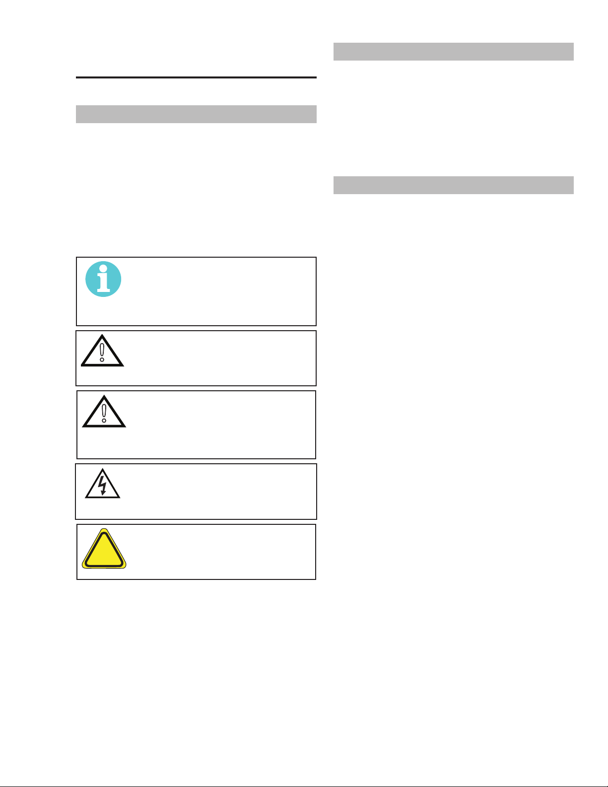
NOTE!
An operation, procedure, or background information which requires
additional emphasis or is helpful in
efcient operation of the system.
CAUTION
!
A procedure which, if not properly
followed, may cause damage to the
equipment.
2.02 EquipmentIdentication
The unit’s identication number (specication or part
number), model, and serial number usually appear on
a data tag attached to the rear panel. Equipment which
does not have a data tag such as torch and cable as-
semblies are identied only by the specication or part
number printed on loosely attached card or the shipping
container. Record these numbers on the bottom of page
i for future reference.
2.03 Receipt Of Equipment
When you receive the equipment, check it against the
invoice to make sure it is complete and inspect the
equipment for possible damage due to shipping. If there
is any damage, notify the carrier immediately to le a
claim. Furnish complete information concerning damage
claims or shipping errors to the location in your area listed
in the inside back cover of this manual.
Include all equipment identication numbers as described
above along with a full description of the parts in error.
Move the equipment to the installation site before
un-crating the unit. Use care to avoid damaging the
equipment when using bars, hammers, etc., to un-crate
the unit.
WARNING
A procedure which, if not properly
followed, may cause injury to the
operator or others in the operating
area.
WARNING
Gives information regarding possible
electrical shock injury. Warnings will
be enclosed in a box such as this.
DANGER
Means immediate hazards which, if
!
Additional copies of this manual may be purchased by
contacting ESAB at the address and phone number in
your area listed on back cover of this manual. Include
the Owner’s Manual number and equipment identication numbers.
Electronic copies of this manual can also be downloaded
at no charge in Acrobat PDF format by going to the ESAB
web site listed below
not avoided, will result in immediate,
serious personal injury or loss of life.
http://www.esab.eu
300X5397 INTRODUCTION
2-1
ESAB CUTMASTER 100
150 mm
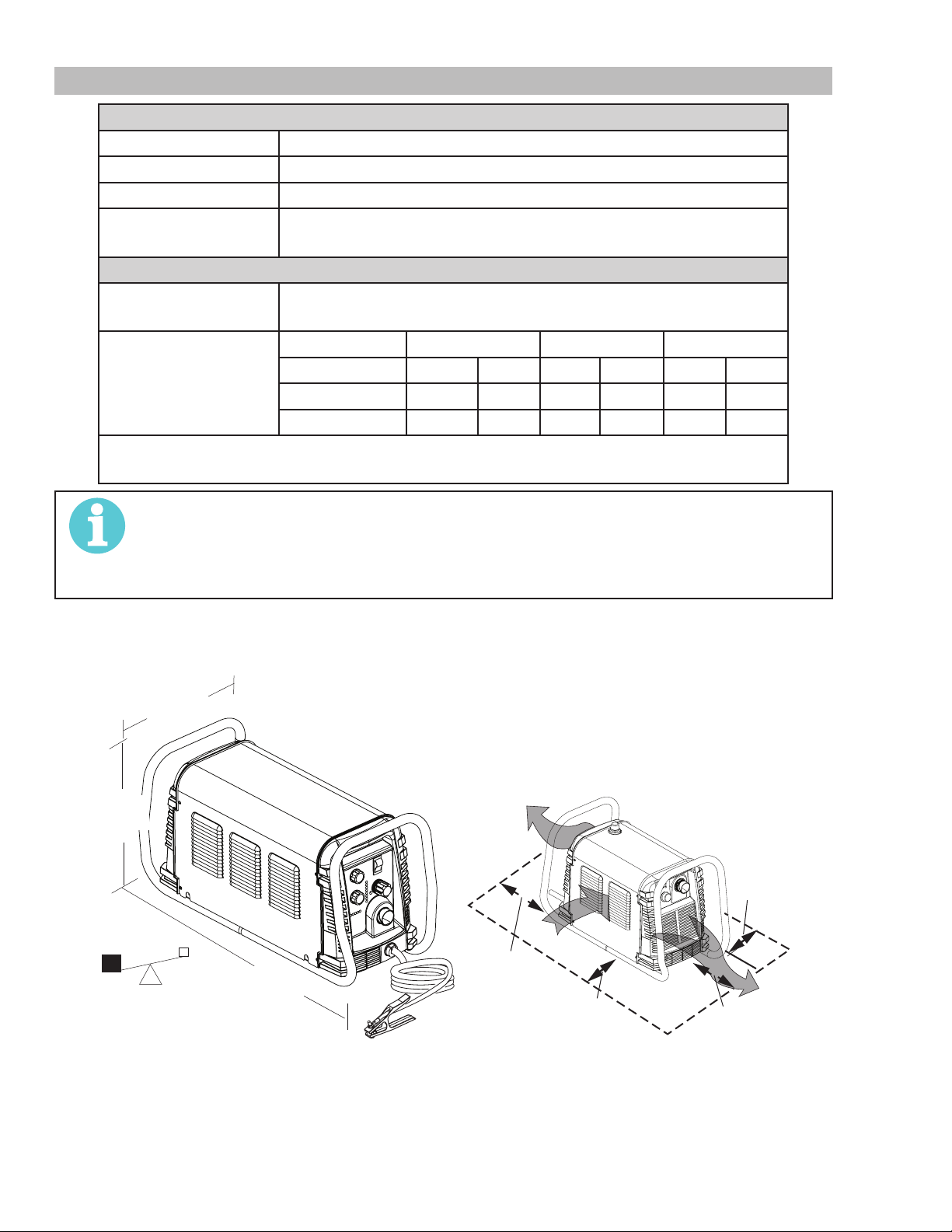
2.04 PowerSupplySpecications
ESABCutmaster100PowerSupplySpecications
Input Power 400 VAC (360 - 440 VAC), Three Phase, 50/60 Hz
Input Power Cable Power Supply includes input cable.
Output Current 30 - 100 Amps, Continuously Adjustable
Power Supply Gas
Filtering Ability
ESAB Cutmaster 100 Power Supply Duty Cycle *
Ambient Tempera-
ture
All Units
* NOTE: The duty cycle will be reduced if the primary input power (AC) is low or
the output voltage (DC) is higher than shown in this chart.
Particulates to 5 Microns
Duty Cycle Ratings @ 40° C (104° F)
Operating Range 0° - 50° C
Duty Cycle 60% 80% 100%
Ratings IEC CE IEC CE IEC CE
Current
DC Voltage
100A -- 80A 80A 70A 70A
120 -- 112 112 92 108
NOTE!
IEC Rating is determined as specied by the International Electro-Technical Commission.
These specications include calculating an output voltage based upon power supply rated
current. To facilitate comparison between power supplies, all manufacturers use this output voltage to determine duty cycle.
Power Supply Dimensions & Weight Ventilation Clearance Requirements
12"
305 mm
Art # A-12887
15"
381 mm
Art # A-07925_AB
6"
150 mm
24"
610 mm
6"
150 mm
6"
30"
63 lb / 28.6 kg
2-2
INTRODUCTION 300X5397
762 mm
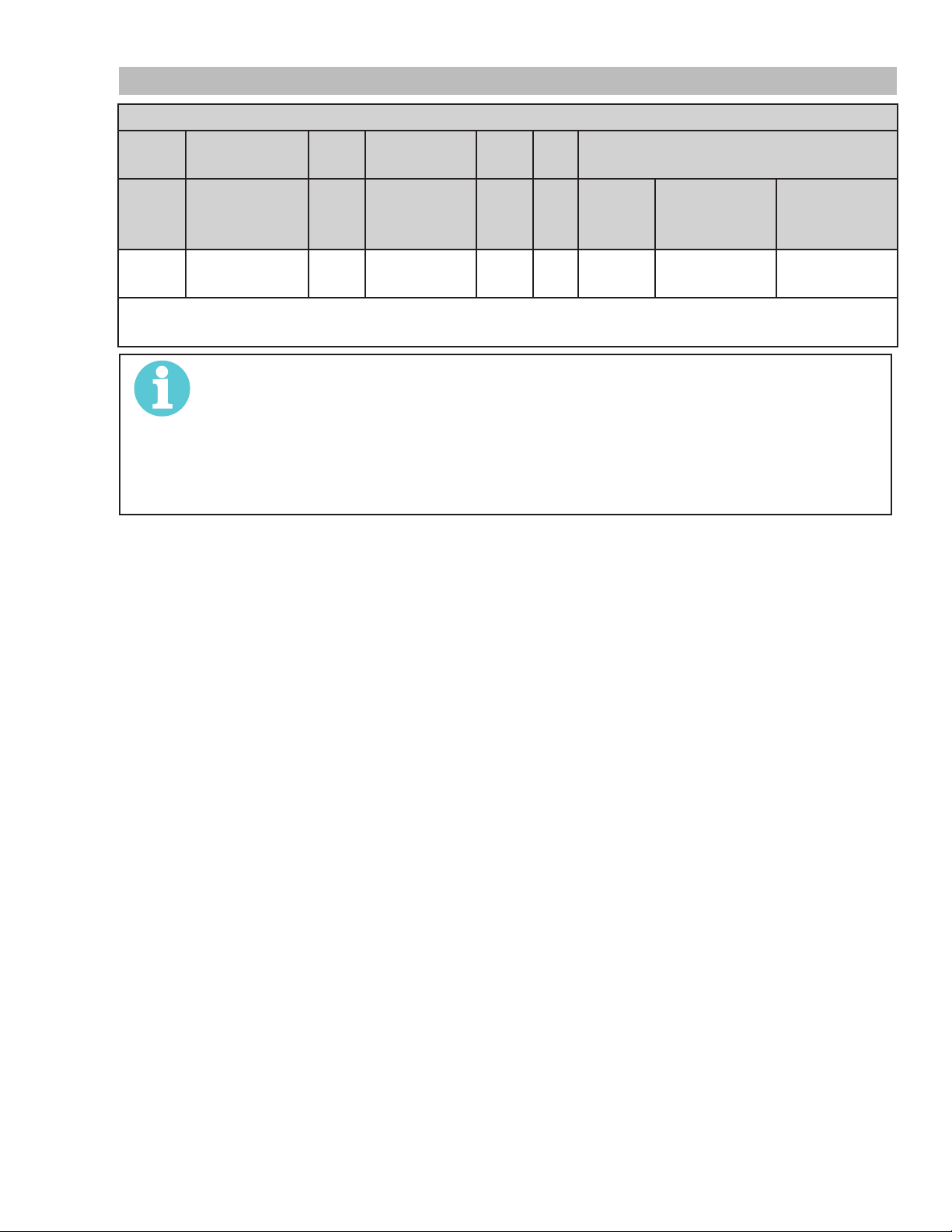
2.05 InputWiringSpecications
ESAB Cutmaster 100 Power Supply Input Cable Wiring Requirements
Power
Input
3
Phase
Input voltage Freq
Volts Hz kVA
400 50 18.7 27 24 32 10 6
Line Voltages with Suggested Circuit Protection and Wire Sizes
Based on National Electric Code and Canadian Electric Code
NOTE!
Refer to Local and National Codes or local authority having jurisdiction for proper wiring
requirements.
The suggested sizes are based on exible power cable with power plug installations. For
hard-wired installations refer to local or national codes.
I1max is taken at TDC rated minimum duty cycle.
I
max
I eff
Fuse
(amps)
ESAB CUTMASTER 100
Suggested Sizes
Flexible
Cord (Min.
AWG)
Flexible
Cord
(Min. mm2)
I1eff is taken at TDC 100% rated duty cycle.
300X5397 INTRODUCTION
2-3

ESAB CUTMASTER 100
Handle and Leads Wrap
e
Ar
and Clamp
Input Power Cord
Gas Inlet
2.06 Power Supply Features
t # A-08359
Control Panel
To rch Leads Receptacl
Filter Assembly
Port
Work Cable
Port for Optional Automation
Interface Cable
Art # A-08547
2-4
INTRODUCTION 300X5397

ESAB CUTMASTER 100
(95 mm)
t # A-02998
15.875" / 403 mm
16 mm
SECTION 2 TORCH:
INTRODUCTION
2T.01 Scope of Manual
This manual contains descriptions, operating instructions
and maintenance procedures for the 1Torch Models
SL100/Manual and SL100/Mechanized Plasma Cutting
Torches. Service of this equipment is restricted to prop-
erly trained personnel; unqualied personnel are strictly
cautioned against attempting repairs or adjustments not
covered in this manual, at the risk of voiding the Warranty.
Read this manual thoroughly. A complete understanding
of the characteristics and capabilities of this equipment
will assure the dependable operation for which it was
designed.
2T.02 General Description
Plasma torches are similar in design to the automotive
spark plug. They consist of negative and positive sections separated by a center insulator. Inside the torch,
the pilot arc starts in the gap between the negatively
charged electrode and the positively charged tip. Once
the pilot arc has ionized the plasma gas, the superheated
column of gas ows through the small orice in the torch
tip, which is focused on the metal to be cut.
10.125" (257 mm)
3.75"
1.17" (29 mm)
2. Mechanized Torch, Model
The standard machine torch has a positioning
tube with rack & pinch block assembly.
9.285" / 236 mm
1.375" / 35 mm
1.75" /
44.5 mm
0.625" /
4.95" / 126 mm
B. Torch Leads Lengths
Hand Torches are available as follows:
• 20 ft / 6.1 m, with ATC connectors
• 50 ft / 15.2 m, with ATC connectors
Machine Torches are available as follows:
Art # A-03322_AB
1.175" / 30 mm
Ar
A single torch lead provides gas from a single source to
be used as both the plasma and secondary gas. The
air ow is divided inside the torch head. Single - gas
operation provides a smaller sized torch and inexpensive
operation.
NOTE!
Refer to Section "2T.05 Introduction to
Plasma", for a more detailed description
of plasma torch operation.
Refer to the Appendix Pages for ad-
ditional specications as related to the
Power Supply used.
2T.03Specications
A. TorchCongurations
1. Hand/Manual Torch, Models
The hand torch head is at 75° to the torch handle.
The hand torches include a torch handle and torch
trigger assembly.
• 5 foot / 1.5 m, with ATC connectors
• 10 foot / 3.05 m, with ATC connectors
• 25 foot / 7.6 m, with ATC connectors
• 50 foot / 15.2 m, with ATC connectors
C. Torch Parts
Starter Cartridge, Electrode, Tip, Shield Cup
D. Parts - In - Place (PIP)
Torch Head has built - in switch
12 VDC circuit rating
E. Type Cooling
Combination of ambient air and gas stream through
torch.
300X5397 INTRODUCTION
2T-1
ESAB CUTMASTER 100
F. Torch Ratings
Manual Torch Ratings
Ambient
Temperature
Duty Cycle 100% @ 100 Amps @ 400 scfh
Maximum Current 100 Amps
Voltage (V
Arc Striking Voltage 7kV
Ambient
Temperature
Duty Cycle 100% @ 100 Amps @ 400 scfh
Maximum Current 120 Amps
Voltage (V
Arc Striking Voltage 7kV
) 500V
peak
Mechanized Torch Ratings
) 500V
peak
104° F
40° C
104° F
40° C
G. Gas Requirements
Manual and Mechanized Torch Gas
Specications
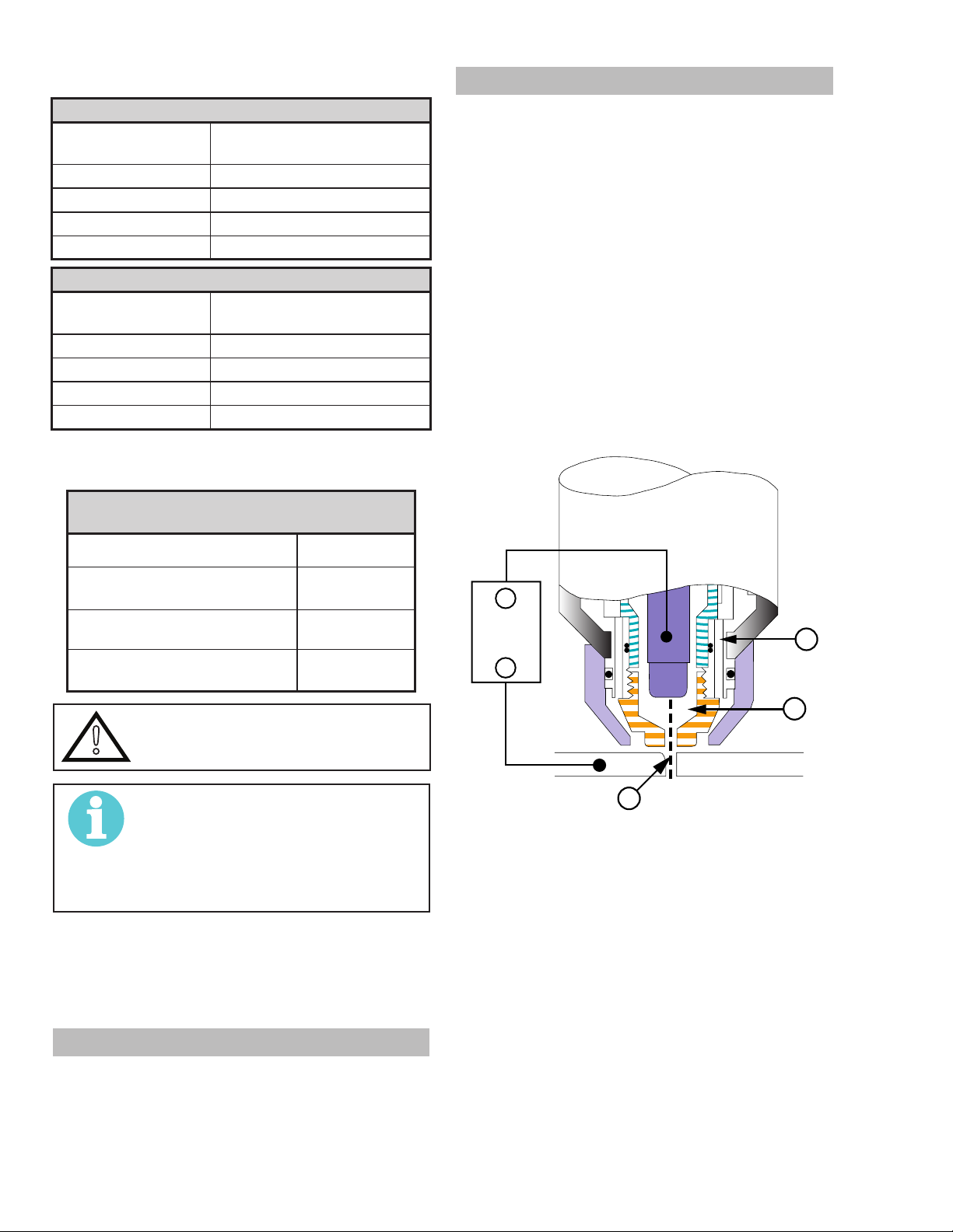
2T.05 Introduction to Plasma
A. Plasma Gas Flow
Plasma is a gas which has been heated to an
extremely high temperature and ionized so that it
becomes electrically conductive. The plasma arc
cutting and gouging processes use this plasma to
transfer an electrical arc to the workpiece. The metal
to be cut or removed is melted by the heat of the arc
and then blown away.
While the goal of plasma arc cutting is separation of
the material, plasma arc gouging is used to remove
metals to a controlled depth and width.
In a Plasma Cutting Torch a cool gas enters Zone B,
where a pilot arc between the electrode and the torch
tip heats and ionizes the gas. The main cutting arc
then transfers to the workpiece through the column
of plasma gas in Zone C.
Gas (Plasma and Secondary) Compressed Air
Operating Pressure
Refer to NOTE
Maximum Input Pressure 125 psi / 8.6 bar
Gas Flow (Cutting and
Gouging)
60 - 95 psi
4.1 - 6.5 bar
300 - 500 scfh
142 - 235 lpm
WARNING
!
This torch is not to be used with
oxygen (O2)
NOTE!
Operating pressure varies with torch
model, operating amperage, and
torch leads length. Refer to gas
pressure settings charts for each
model.
H. Direct Contact Hazard
For standoff tip the recommended standoff is 3/16
inches / 4.7 mm.
2T.04 Options And Accessories
_
Power
Supply
A
+
B
Workpiece
C
Typical Torch Head Detail
By forcing the plasma gas and electric arc through a
small orice, the torch delivers a high concentration
of heat to a small area. The stiff, constricted plasma
arc is shown in Zone C. Direct current (DC) straight
polarity is used for plasma cutting, as shown in the
illustration.
Zone A channels a secondary gas that cools the
torch. This gas also assists the high velocity plasma
gas in blowing the molten metal out of the cut allowing for a fast, slag - free cut.
A-00002
For options and accessories, see section 6.
2T-2
INTRODUCTION 300X5397

B. Gas Distribution
A-02997
r
up
To
up
up
Remote Pendant
To
The single gas used is internally split into plasma
and secondary gases.
ESAB CUTMASTER 100
The plasma gas ows into the torch through the
negative lead, through the starter cartridge, around
the electrode, and out through the tip orice.
The secondary gas ows down around the outside
of the torch starter cartridge, and out between the
tip and shield cup around the plasma arc.
C. Pilot Arc
When the torch is started a pilot arc is established
between the electrode and cutting tip. This pilot arc
creates a path for the main arc to transfer to the work.
D. Main Cutting Arc
DC power is also used for the main cutting arc. The
negative output is connected to the torch electrode
through the torch lead. The positive output is connected to the workpiece via the work cable and to
the torch through a pilot wire.
E. Parts - In - Place (PIP)
The torch includes a 'Parts - In - Place' (PIP) circuit.
When the shield cup is properly installed, it closes
a switch. The torch will not operate if this switch is
open.
AT C
AT C
To AT C
PIP Sw itch
CNC Start
PIP Sw itch
Automation To rch
PIP Sw itch
Sh ield C
Sh ield C
Art # A-08168
Sh ield C
Parts - In - Place Circuit Diagram for Machine Torch
To Control
Cable Wiring
Parts - In - Place Circuit Diagram for Hand Torch
Torch Switch
PIP Switch
Torch Trigge
Shield Cup
300X5397 INTRODUCTION
2T-3

ESAB CUTMASTER 100
This Page Intentionally Blank
2T-4
INTRODUCTION 300X5397

ESAB CUTMASTER 100
!
SECTION 3 SYSTEM:
INSTALLATION
3.01 Unpacking
1. Use the packing lists to identify and account for
each item.
2. Inspect each item for possible shipping damage.
If damage is evident, contact your distributor and
/ or shipping company before proceeding with the
installation.
3. Record Power Supply and Torch model and serial
numbers, purchase date and vendor name, in the
information block at the front of this manual.
3.02 Lifting Options
The Power Supply includes a handle for hand lifting
only. Be sure unit is lifted and transported safely and
securely.
WARNING
Do not touch live electrical parts.
Disconnect input power cord before
moving unit.
3.03 Primary Input Power Connections
CAUTION
!
The following illustration and directions are for wiring
three phase input power.
Check your power source for correct voltage before plugging in or
connecting the unit. The primary
power source, fuse, and any extension cords used must conform to
local electrical code and the recommended circuit protection and wiring
requirements as specied in Section
2.
Input Power Cable Connections
Three-Phase (3ø)
L1
L2
L3
L4
GND
Three Phase Input Power Wiring
Art # A-08548
WARNING
FALLING EQUIPMENT can cause
serious personal injury and can damage equipment.
HANDLE is not for mechanical lifting.
• Only persons of adequate physical strength should
lift the unit.
• Lift unit by the handles, using two hands. Do not
use straps for lifting.
• Use optional cart or similar device of adequate
capacity to move unit.
• Place unit on a proper skid and secure in place
before transporting with a fork lift or other vehicle.
A. Connections to Three Phase Input Power
WARNING
Disconnect input power from the
power supply and input cable before
attempting this procedure.
These instructions are for replacing the input power and
or cable for 400 VAC Power Supply to Three - Phase
input power.
1. Remove the Power Supply cover per instructions
found in section 5.
2. Disconnect the original input power cable from
the main input contactor and the chassis ground
connection.
3. Loosen the through - hole protector on the back
panel of the power supply. Pull the original power
cable out of the power supply.
4. Using a customer supplied four - conductor input
power cable for the voltage desired, strip back
the insulation on the individual wires.
5. Pass the cable being used through the access
300X5397 INSTALLATION
opening in the back panel of the power supply.
Refer to Section 2 for power cable specications.
3-1

ESAB CUTMASTER 100
Regulator/Filter
Gas Supply
Hose
to 1/4” (6mm) Fitting
CAUTION
!
The primary power source and power cable must conform to local electrical code and the recommended
circuit protection and wiring require-
ments (refer to table in Section 2).
6. Connect the wires as follows.
• Wires to L1, L2 and L3 input. It does not
matter what order these wires are attached.
See previous illustration and on label in the
power supply.
• Green / Yellow wire to Ground.
7. With a little slack in the wires, tighten the through
- hole protector to secure the power cable.
8. Reinstall the Power Supply cover per instructions
found in section 5.
9. Connect the opposite end of individual wires to
a customer supplied plug or main disconnect.
10. Connect the input power cable (or close the main
disconnect switch) to supply power.
Assembly
Inlet Port
Hose Clamp
1/4 NPT or ISO-R
Art # A-07943
Air Connection to Inlet Port
Installing Optional Single - Stage Air Filter
An optional lter kit is recommended for improved ltering with compressed air, to keep moisture and debris
out of the torch.
1. Attach the Single - Stage Filter Hose to the Inlet
Port.
3.04 Gas Connections
Connecting Gas Supply to Unit
The connection is the same for compressed air or high
pressure cylinders. Refer to the following two subsec-
tions if an optional air line lter is to be installed.
1. Connect the air line to the inlet port. The illustra-
tion shows typical ttings as an example.
NOTE!
For a secure seal, apply thread
sealant to the tting threads, according to manufacturer's instructions.
Do not use Teon tape as a thread
sealer, as small particles of the tape
may break off and block the small air
passages in the torch.
2. Attach the Filter Assembly to the lter hose.
3. Connect the air line to the Filter. The illustration
shows typical ttings as an example.
INSTALLATION 300X5397
3-2

ESAB CUTMASTER 100
t # A-07944
Hose Clam
Regulator/Filter
NOTE!
For a secure seal, apply thread sealant to the tting threads, according to the maker's
instructions. Do Not use Teon tape as a thread sealer, as small particles of the tape may
break off and block the small air passages in the torch. Connect as follows:
Assembly
Inlet Port
Ar
p
Gas Supply
Hose
1/4 NPT to 1/4"
(6mm) Fitting
Optional Single - Stage Filter Installation
Installing Optional Two - Stage Air Filter Kit
This optional two - stage air line lter is also for use on compressed air shop systems. Filter removes moisture and
contaminants to at least 5 microns.
Connect the air supply as follows:
1. Attach the Two Stage Filter bracket to the back of the power supply per instructions supplied with the lter
assembly.
NOTE!
For a secure seal, apply thread sealant to the tting threads according to manufacturer's
instructions. Do Not use Teon tape as a thread sealer as small particles of the tape may
break off and block the small air passages in the torch.
2. Connect the two stage lter outlet hose to the inlet port of the Regulator / Filter Assembly.
3. Use customer - supplied ttings to connect the air line to the Filter. A 1/4 NPT to 1/4" hose barbed tting is
shown as an example.
300X5397 INSTALLATION
3-3

ESAB CUTMASTER 100
Regulator/Filter
wo Stage
Art # A-07945_AC
Hose Clamp
Assembly
Regulator
Input
Gas Supply
Hose
1/4 NPT to 1/4”
(6mm) Fitting
2-Stage Filter
Inlet Port (IN)
Outlet Port
(OUT)
T
Filter
Assembly
Optional Two - Stage Filter Installation
Using High Pressure Air Cylinders
When using high pressure air cylinders as the air supply:
1. Refer to the manufacturer’s specications for installation and maintenance procedures for high pressure
regulators.
2. Examine the cylinder valves to be sure they are clean and free of oil, grease or any foreign material. Briey
open each cylinder valve to blow out any dust which may be present.
3. The cylinder must be equipped with an adjustable high - pressure regulator capable of outlet pressures up
to 100 psi (6.9 bar) maximum and ows of at least 300 scfh (141.5 lpm).
4. Connect supply hose to the cylinder.
NOTE!
Pressure should be set at 100 psi (6.9 bar) at the high pressure cylinder regulator.
Supply hose must be at least 1/4 inch (6 mm) I.D.
For a secure seal, apply thread sealant to the tting threads, according to manufacturer's
instructions. Do Not use Teon tape as a thread sealer, as small particles of the tape may
break off and block the small air passages in the torch.
INSTALLATION 300X5397
3-4
SECTION 3 TORCH:
Wo
INSTALLATION
ESAB CUTMASTER 100
3. Place a welding lter lens in front of the torch and
turn on the air. Do not start an arc!
Any oil or moisture in the air will be visible on the lens.
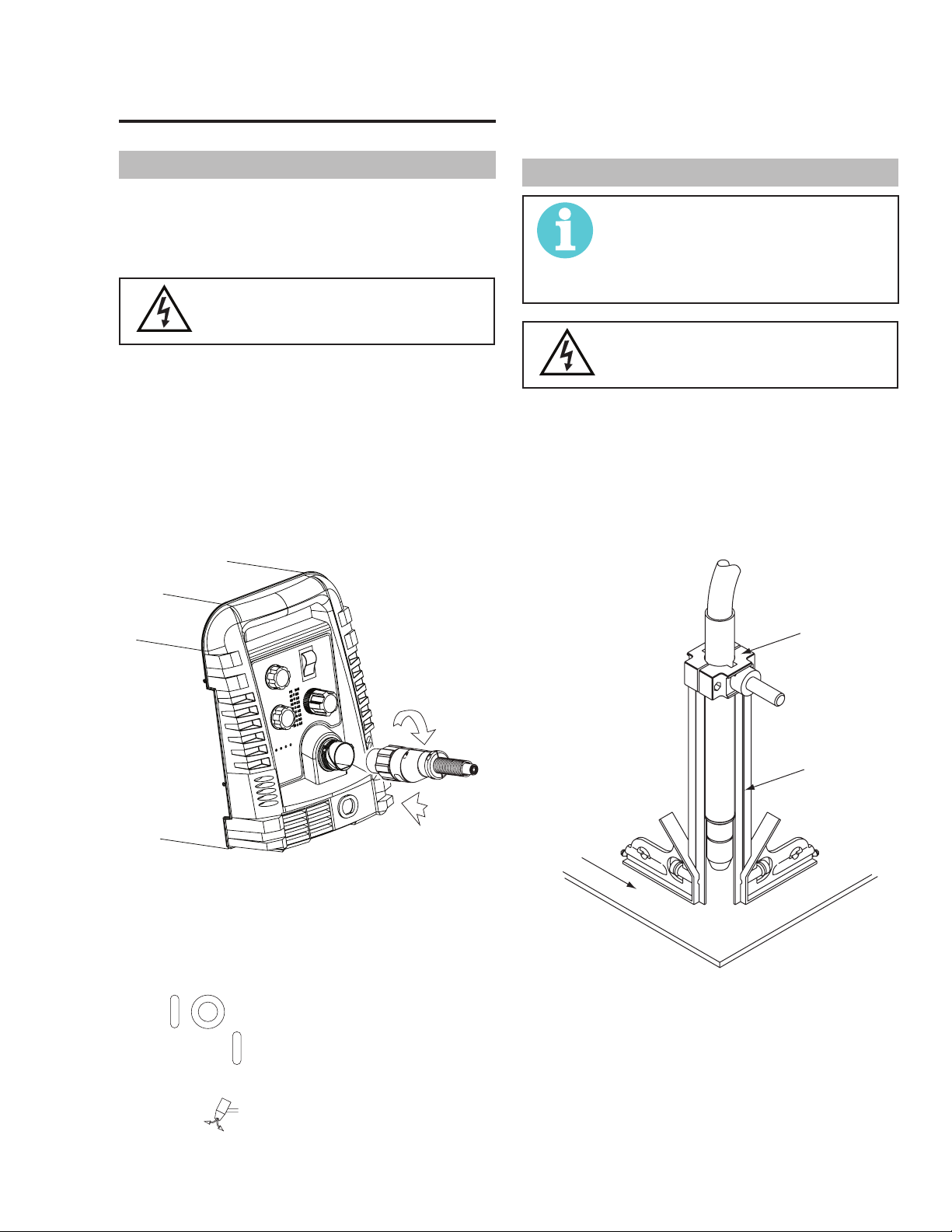
3T.01 Torch Connections
If necessary, connect the torch to the Power Supply.
Connect only the ESAB model SL100 / Manual or SL100
/ Mechanical Torch to this power supply. Maximum torch
leads length is 100 feet / 30.5 m, including extensions.
WARNING
Disconnect primary power at the
1. Align the ATC male connector (on the torch lead)
2. Secure the connection by turning the locking nut
source before connecting the torch.
with the female receptacle. Push the male connector into the female receptacle. The connectors should push together with a small amount
of pressure.
clockwise until it clicks. DO NOT use the locking
nut to pull the connection together. Do not use
tools to secure the connection.
3T.02 Setting Up Mechanical Torch
NOTE!
An adapter is required to be installed
in the power supply if converting
a hand torch system to operate a
machine torch.
WARNING
Disconnect primary power at the
The mechanical torch includes a positioning tube with
rack and pinch block assembly.
1. Mount the torch assembly on the cutting table.
2. To obtain a clean vertical cut, use a square to
source before connecting the torch.
align the torch perpendicular to the surface of
the workpiece.
Pinch Block
Assembly
2
1
Art # A-07885
Connecting the Torch to the Power Supply
3. The system is ready for operation.
Check Air Quality
To test the quality of air:
1. / Put the ON / OFF switch in the ON (up)
position.
2. Put the Function Control switch in the SET posi-
tion.
Square
rkpiece
A-02585
Mechanical Torch Set - Up
3. The proper torch parts (shield cup, tip, start cartridge, and electrode) must be installed for the
type of operation. Refer to Section 4T.07, Torch
Parts Selection for details.
300X5397 INSTALLATION
3T-1

ESAB CUTMASTER 100
This Page Intentionally Blank
3T-2
INSTALLATION 300X5397

SECTION 4 SYSTEM:
+
12
3
5
6
7
9
10
!
OPERATION
4.01 Front Panel Controls / Features
SeeIllustrationfornumberingIdentication
1. Output Current Control
Sets the desired output current. Output settings
up to 60 Amps may be used for drag cutting (with
the torch tip contacting the workpiece) or higher for
standoff cutting.
2. Function Control
ESAB CUTMASTER 100
nect input power, correct the fault, and restart the
unit. Refer to Section 5 for details.
4
MAX
MIN
A
PSI BAR
MAXMAX
MINMIN
!
+
Function Control Knob, Used to select between the
different operating modes.
and torch and leads and to adjust gas pressure.
restarting of the Pilot Arc for uninterrupted cutting.
Once a cutting arc is established, the torch switch
can be released. The cutting arc will remain ON until
the torch is lifted away from the work piece, the torch
leaves the edge of the work piece the torch switch
is activated again or if one of the system interlocks
is activated.
3. ON OFF Power Switch
/ ON / OFF Switch controls input power to
the power supply. Up is ON, down is OFF.
4. Air/Gas Pressure Control
SET Used to purge the air through the unit
RUN Used for general cutting operations
RAPID AUTO RESTART Allows for faster
LATCH Used for longer hand held cuts.
Art# A-07886
8
6. Temp Indicator
Indicator is normally OFF. Indicator is ON when
internal temperature exceeds normal limits. Let the
unit cool before continuing operation.
7. Gas Indicator
Indicator is ON when minimum input gas pressure
for power supply operation is present. Minimum
pressure for power supply operation is not sufcient
for torch operation.
8. DC Indicator
Indicator is ON when DC output circuit is active.
9.
Fault Error Indicator
Indicator is ON when Fault circuit is active. See section 5 for explanations of fault lights.
The Pressure Control is used in the "SET"
mode to adjust the air/gas pressure. Pull the knob
out to adjust and push in to lock.
5. AC Indicator
Steady light indicates power supply is ready for operation. Blinking light indicates unit is in protective
interlock mode. Shut unit OFF, shut OFF or discon-
300X5397 OPERATION
4-1

ESAB CUTMASTER 100
Art # A-08170
Art # A-04509
10. Pressure Indicators
Connect Work Cable
PSI BAR
MAX MAX
90 6.3
85 5.9
80
75
70
65
MINMIN
The Indicators will illuminate according to the pres-
sure set by the Pressure Control Knob (number 4).
5.5
5.2
4.8
4.5
4.02 Preparations for Operation
At the start of each operating session:
WARNING
Disconnect primary power at the
source before assembling or disassembling power supply, torch parts,
or torch and leads assemblies.
Torch Parts Selection
Check the torch for proper assembly and appropriate
torch parts. The torch parts must correspond with
the type of operation, and with the amperage output
of this Power Supply (100 amps maximum). Refer to
Section 4T.07 and following for torch parts selection.
Torch Connection
Check that the torch is properly connected. Only
ESAB model SL100 / Manual or SL100 / Mechanical Torches may be connected to this Power Supply.
See Section 3T of this manual.
Clamp the work cable to the workpiece or cutting
table. The area must be free from oil, paint and rust.
Connect only to the main part of the workpiece; do
not connect to the part to be cut off.
Power ON
Place the Power Supply ON / OFF switch to the ON
(up) position. AC indicator turns ON.
Gas indicator turns ON if there is sufcient gas
pressure for power supply operation and the cooling
fans turn ON.
NOTE!
Minimum pressure for power supply
operation is lower than minimum for
torch operation.
The cooling fans will turn ON as
soon as the unit is turned ON. After
the unit is idle for ten (10) minutes
the fans will turn OFF. The fans will
come back ON as soon as the torch
switch (Start Signal) is activated or if
the unit is turned off, then turned ON
again. If an over temperature condition occurs, the fans will continue to
run while the condition exists and for
a ten (10) minute period once the
condition is cleared.
Check Primary Input Power Source
1. Check the power source for proper input voltage. Make sure the input power source meets
the power requirements for the unit per Section
2, Specications.
2. Connect the input power cable (or close the main
disconnect switch) to supply power to the system.
Air Source
Ensure source meets requirements (refer to Section
2). Check connections and turn air supply ON.
4-2
OPERATION 300X5397
Set Operating Pressure
1. Place the Power Supply Function Control knob
to the SET position. Gas will ow.
2. For Standoff cutting, adjust gas pressure from 70
- 85 psi / 4.8 - 5.9 bar (LED's in center of control
panel). Refer to the Standoff chart for pressure
setting details.

1
2
MIN
MAX
A
PSI BAR
MAXMAX
MINMIN
!
+
Art# A-07946
STANDOFF
ESAB Cutmaster 100 Gas Pressure Settings
Leads Length
Up to 25' (7.6 m)
Each additional
25' (7.6 m)
SL100
(Hand Torch)
80 psi
5.5 bar
Add 5 psi 0.4
bar
SL100
(Mechanized Torch)
80 psi
5.5 bar
Add 5 psi 0.4 bar
ESAB CUTMASTER 100
Cutting Operation
When the torch leaves the workpiece during cutting
operations with the Function Control Knob in the
RUN position, there is a brief delay in restarting
the pilot arc. With the knob in the RAPID AUTO
RESTART position, when the torch leaves the workpiece the pilot arc restarts instantly, and the cutting
arc restarts instantly when the pilot arc contacts the
workpiece. (Use the 'Rapid Auto Restart' position
when cutting expanded metal or gratings, or in gouging or trimming operations when an uninterrupted
restart is desired). And with the knob in the LATCH
position the main cutting arc will be maintained after
the torch switch is released.
Typical Cutting Speeds
Cutting speeds vary according to torch output amperage, the type of material being cut, and operator
skill. Refer to Section 4T.08 and following for greater
details.
Output current setting or cutting speeds may be
reduced to allow slower cutting when following a
line, or using a template or cutting guide while still
producing cuts of excellent quality.
Postow
3. For Drag cutting, adjust gas pressure from 75 -
95 psi / 5.2 - 6.5 bar (LED's in center of control
panel). Refer to the Drag Cutting chart for pressure setting details.
Drag (60 Amps or less)
ESAB Cutmaster 100 Gas Pressure
Settings
Leads Length
Up to 25' (7.6 m)
Each additional
25' (7.6 m)
SL100
(Hand Torch)
80 psi
5.5 bar
Add 5 psi
0.4 bar
tinues to ow for approximately 20 seconds. During
post - ow, if the user moves the trigger release to
the rear and presses the trigger, the pilot arc starts.
The main arc transfers to the workpiece if the torch
tip is within transfer distance to the workpiece.
Shutdown
/ Turn the ON / OFF switch to OFF (down).
All Power Supply indicators shut OFF. Unplug
the input power cord or disconnect input power.
Power is removed from the system.
Select Current Output Level
1. Place the Function Control Knob in one of the
three operating positions available:
RUN,
Release the trigger to stop the cutting arc. Gas con-
RAPID AUTO RESTART,
or LATCH. Gas ow stops.
2. Set the output current to desired amperage with
the Output Current Control Knob.
300X5397 OPERATION
4-3

ESAB CUTMASTER 100
This Page Intentionally Blank
4-4
OPERATION 300X5397

SECTION 4 TORCH:
A-03510_AB
Kerf Width
Cut Surface
Bevel Angle
Top Edge
Rounding
Cut Surface
Drag Lines
Dross
Build-Up
Top
Spatter
A-00007
ESAB CUTMASTER 100
Shown)
OPERATION
4T.01 Torch Parts Selection
Depending on the type of operation to be done determines the torch parts to be used.
Type of operation:
Drag cutting, standoff cutting or gouging
Torch parts:
Shield Cup, Cutting Tip, Electrode and Starter
Cartridge
NOTE!
Refer to Section 4T.07 and following
for additional information on torch
parts.
Change the torch parts for a different operation as follows:
WARNING
Disconnect primary power at the
source before assembling or disassembling power supply, torch parts,
or torch and leads assemblies.
NOTE!
The shield cup holds the tip and
starter cartridge in place. Position
the torch with the shield cup facing
upward to keep these parts from falling out when the cup is removed.
3. Install the replacement Electrode by pushing it
straight into the torch head until it clicks.
4. Install the starter cartridge and desired tip for the
operation into the torch head.
5. Hand tighten the shield cup assembly until it is
seated on the torch head. If resistance is felt
when installing the cup, check the threads before
proceeding.
4T.02 Cut Quality
NOTE!
Cut quality depends heavily on
setup and parameters such as torch
standoff, alignment with the workpiece, cutting speed, gas pressures,
and operator ability.
Cut quality requirements differ depending on application. For instance, nitride build - up and bevel angle
may be major factors when the surface will be welded
after cutting. Dross - free cutting is important when nish cut quality is desired to avoid a secondary cleaning
operation. The following cut quality characteristics are
illustrated in the following gure:
1. Unscrew and remove the shield cup assembly
from the torch head.
2. Remove the Electrode by pulling it straight out
of the Torch Head.
Large O-Ring
Torch Head
Electrode
Small O-Ring
Cut Surface
Start Cartridge
Tip
Shield Cup
Torch Parts (Drag Shield Cap & Shield Cup Body
300X5397 OPERATION
The desired or specied condition (smooth or rough)
of the face of the cut.
Nitride Build - Up
Nitride deposits can be left on the surface of the cut
when nitrogen is present in the plasma gas stream.
These buildups may create difculties if the material
is to be welded after the cutting process.
Cut Quality Characteristics
4T-1

ESAB CUTMASTER 100
!
Right Side
Cut Angle
Left Side
Cut Angle
A-00512
Bevel Angle
The angle between the surface of the cut edge and
a plane perpendicular to the surface of the plate.
A perfectly perpendicular cut would result in a 0°
bevel angle.
Top - Edge Rounding
Rounding on the top edge of a cut due to wearing
from the initial contact of the plasma arc on the
workpiece.
Bottom Dross Buildup
Molten material which is not blown out of the cut area
and resolidies on the plate. Excessive dross may
require secondary cleanup operations after cutting.
Kerf Width
The width of the cut (or the width of material removed
during the cut).
Top Spatter (Dross)
Piloting
Piloting is harder on parts life than actual cutting
because the pilot arc is directed from the electrode
to the tip rather than to a workpiece. Whenever
possible, avoid excessive pilot arc time to improve
parts life.
Torch Standoff
Improper standoff (the distance between the torch tip
and workpiece) can adversely affect tip life as well as
shield cup life. Standoff may also signicantly affect
the bevel angle. Reducing standoff will generally
result in a more square cut.
Edge Starting
For edge starts, hold the torch perpendicular to the
workpiece with the front of the tip near (not touching)
the edge of the workpiece at the point where the cut
is to start. When starting at the edge of the plate, do
not pause at the edge and force the arc to "reach"
for the edge of the metal. Establish the cutting arc
as quickly as possible.
Top spatter or dross on the top of the cut caused by
slow travel speed, excess cutting height, or cutting
tip whose orice has become elongated.
4T.03 General Cutting Information
WARNING
Disconnect primary power at the
source before disassembling the
power supply, torch, or torch leads.
Frequently review the Important
Safety Precautions at the front of
this manual. Be sure the operator is
equipped with proper gloves, clothing, eye and ear protection. Make
sure no part of the operator’s body
comes into contact with the workpiece while the torch is activated.
CAUTION
!
Sparks from the cutting process can
cause damage to coated, painted,
and other surfaces such as glass,
plastic and metal.
NOTE!
Handle torch leads with care and
protect them from damage.
Direction of Cut
In the torches, the plasma gas stream swirls as it
leaves the torch to maintain a smooth column of
gas. This swirl effect results in one side of a cut being more square than the other. Viewed along the
direction of travel, the right side of the cut is more
square than the left.
Side Characteristics Of Cut
To make a square - edged cut along an inside
diameter of a circle, the torch should move counterclockwise around the circle. To keep the square
edge along an outside diameter cut, the torch should
travel in a clockwise direction.
Dross
When dross is present on carbon steel, it is commonly referred to as either “high speed, slow speed,
or top dross”. Dross present on top of the plate is
4T-2
OPERATION 300X5397

normally caused by too great a torch to plate dis-
A-00024_AB
Shield Cup
Torch
Standoff Distance
1/8" - 3/8" (3 - 9mm)
A-02986
Trigger
Trigger Release
tance. "Top dross" is normally very easy to remove
and can often be wiped off with a welding glove.
"Slow speed dross" is normally present on the bottom
edge of the plate. It can vary from a light to heavy
bead, but does not adhere tightly to the cut edge,
and can be easily scraped off. "High speed dross"
usually forms a narrow bead along the bottom of
the cut edge and is very difcult to remove. When
cutting a troublesome steel, it is sometimes useful
to reduce the cutting speed to produce "slow speed
dross". Any resultant cleanup can be accomplished
by scraping, not grinding.
4T.04 Hand Torch Operation
ESAB CUTMASTER 100
Standoff Cutting With Hand Torch
NOTE!
For best parts performance and life,
always use the correct parts for the
type of operation.
1. The torch can be comfortably held in one hand
or steadied with two hands. Position the hand to
press the Trigger on the torch handle. With the
hand torch, the hand may be positioned close to
the torch head for maximum control or near the
back end for maximum heat protection. Choose
the holding technique that feels most comfortable
and allows good control and movement.
NOTE!
The tip should never come in contact with the workpiece except during drag cutting operations.
2. Depending on the cutting operation, do one of
the following:
a. For edge starts, hold the torch perpendicular
to the workpiece with the front of the tip on
the edge of the workpiece at the point where
the cut is to start.
Standoff Distance
3. Hold the torch away from your body.
4. Slide the trigger release toward the back of the
torch handle while simultaneously squeezing the
trigger. The pilot arc will start.
5. Bring the torch within transfer distance to the
work. The main arc will transfer to the work, and
the pilot arc will shut off.
NOTE!
The gas preow and postow are a
characteristic of the power supply
and not a function of the torch.
b. For standoff cutting, hold the torch 1/8 - 3/8
in (3-9 mm) from the workpiece as shown
below.
300X5397 OPERATION
4T-3

ESAB CUTMASTER 100
3
4
Art # A-03383
Tr igger
2
1
Tr igger Release
Art # A-04034
A-03539
Non-Conductive
Straight Edge
Cutting Guide
4T-4
OPERATION 300X5397
6. Cut as usual. Simply release the trigger assembly to stop cutting.
7. Follow normal recommended cutting practices as
provided in the power supply operator's manual.
NOTE!
When the shield cup is properly installed, there is a slight gap between
the shield cup and the torch handle.
Gas vents through this gap as part
of normal operation. Do not attempt
to force the shield cup to close this
gap. Forcing the shield cup against
the torch head or torch handle can
damage components.
8. For a consistent standoff height from the workpiece, install the standoff guide by sliding it
onto the torch shield cup. Install the guide with
the legs at the sides of the shield cup body to
maintain good visibility of the cutting arc. During
operation, position the legs of the standoff guide
against the workpiece.
Shield Cup
Standoff Guide
Torch Tip
Workpiece
Shield Cup With Straight Edge
The drag shield cup can be used with a non conductive straight edge to make straight cuts by hand.
WARNING
The straight edge must be nonconductive.
Using Drag Shield Cup With Straight Edge
The crown shield cup functions best when cutting
3/16 inch (4.7 mm) solid metal with relatively smooth
surface.
Drag Cutting With a Hand Torch
Drag cutting works best on metal 1/4" (6 mm) thick
or less.
NOTE!
Drag cutting can only be performed
at 60 amps or less.
For best parts performance and life,
always use the correct parts for the
type of operation.
1. Install the drag cutting tip and set the output current.
2. The torch can be comfortably held in one hand
or steadied with two hands. Position the hand to
press the Trigger on the torch handle. With the
hand torch, the hand may be positioned close to
the torch head for maximum control or near the
back end for maximum heat protection. Choose
the holding technique that feels most comfortable
and allows good control and movement.
3. Keep the torch in contact with the workpiece
during the cutting cycle.
4. Hold the torch away from your body.
5. Slide the trigger release toward the back of the
torch handle while simultaneously squeezing the
trigger. The pilot arc will start.

ESAB CUTMASTER 100
A-02986
Trigger
Trigger Release
3
4
Art # A-03383
Tr igger
2
1
Tr igger Release
A-02986
Trigger
Trigger Release
Piercing With Hand Torch
1. The torch can be comfortably held in one hand
or steadied with two hands. Position the hand to
press the Trigger on the torch handle. With the
hand torch, the hand may be positioned close to
the torch head for maximum control or near the
back end for maximum heat protection. Choose
the technique that feels most comfortable and
allows good control and movement.
6. Bring the torch within transfer distance to the
work. The main arc will transfer to the work, and
the pilot arc will shut off.
NOTE!
The gas preow and postow are a
characteristic of the power supply
and not a function of the torch.
NOTE!
The tip should never come in contact with the workpiece except during drag cutting operations.
2. Angle the torch slightly to direct blowback par-
ticles away from the torch tip (and operator)
rather than directly back into it until the pierce is
complete.
3. In a portion of the unwanted metal start the
pierce off the cutting line and then continue the
cut onto the line. Hold the torch perpendicular to
the workpiece after the pierce is complete.
4. Hold the torch away from your body.
5. Slide the trigger release toward the back of the
torch handle while simultaneously squeezing the
trigger. The pilot arc will start.
7. Cut as usual. Simply release the trigger assembly to stop cutting.
8. Follow normal recommended cutting practices as
provided in the power supply operator's manual.
NOTE!
When the shield cup is properly in-
the shield cup and the torch handle.
Gas vents through this gap as part
stalled, there is a slight gap between
of normal operation. Do not attempt
to force the shield cup to close this
gap. Forcing the shield cup against
the torch head or torch handle can
damage components.
300X5397 OPERATION
6. Bring the torch within transfer distance to the
work. The main arc will transfer to the work, and
the pilot arc will shut off.
NOTE!
The gas preow and postow are a
characteristic of the power supply
and not a function of the torch
When the shield cup is properly installed, there is a slight gap between
the shield cup and the torch handle.
Gas vents through this gap as part
of normal operation. Do not attempt
to force the shield cup to close this
gap. Forcing the shield cup against
the torch head or torch handle can
damage components.
4T-5

ESAB CUTMASTER 100
!
35°
Workpiece
Torch Head
Standoff Height
A-00941_AB
7. Clean spatter and scale from the shield cup and
the tip as soon as possible. Spraying the shield
cup in anti - spatter compound will minimize the
amount of scale which adheres to it.
Cutting speed depends on material, thickness, and the
operator’s ability to accurately follow the desired cut line.
The following factors may have an impact on system
performance:
• Torch parts wear
• Air quality
• Line voltage uctuations
• Torch standoff height
• Proper work cable connection
4T.05 Gouging
WARNING
Be sure the operator is equipped
with proper gloves, clothing, eye and
ear protection and that all safety precautions at the front of this manual
have been followed. Make sure no
part of the operator’s body comes in
contact with the workpiece when the
torch is activated.
Disconnect primary power to the
system before disassembling the
torch, leads, or power supply.
Torch Travel Speed
NOTE!
Refer to Appendix Pages for additional information as related to the
Power Supply used.
Optimum torch travel speed is dependent on current
setting, lead angle, and mode of operation (hand or
machine torch).
Current Setting
Current settings depend on torch travel speed,
mode of operation (hand or machine torch), and the
amount of material to be removed.
Pressure Setting
Even though the setting is within the specied range,
if the torch does not pilot well the pressure may need
to be reduced.
Lead Angle
The angle between the torch and workpiece depends
on the output current setting and torch travel speed.
The recommended lead angle is 35°. At a lead angle
greater than 45° the molten metal will not be blown
out of the gouge and may be blown back onto the
torch. If the lead angle is too small (less than 35°),
less material may be removed, requiring more passes. In some applications, such as removing welds
or working with light metal, this may be desirable.
CAUTION
!
Sparks from plasma gouging can
cause damage to coated, painted or
other surfaces such as glass, plastic, and metal.
Check torch parts. The torch parts
must correspond with the type of
operation. Refer to Section 4T.07,
Torch Parts Selection.
Gouging Parameters
Gouging performance depends on parameters such
as torch travel speed, current level, lead angle (the
angle between the torch and workpiece), and the dis-
tance between the torch tip and workpiece (standoff).
CAUTION
!
Touching the torch tip or shield cup
to the work surface will cause excessive parts wear.
Gouging Angle and Standoff Distance
Standoff Distance
The tip to work distance affects gouge quality and
depth. Standoff distance of 1/8 - 1/4 inch (3 - 6
mm) allows for smooth, consistent metal removal.
Smaller standoff distances may result in a severance
cut rather than a gouge. Standoff distances greater
than 1/4 inch (6 mm) may result in minimal metal
removal or loss of transferred main arc.
4T-6
OPERATION 300X5397

Slag Buildup
Standoff Distance
Straight Arc
Trailing Arc
Leading Arc
Direction of Torch Travel
A-02586
Slag generated by gouging on materials such as carbon and stainless steels, nickels, and alloyed steels,
can be removed easily in most cases. Slag does not
obstruct the gouging process if it accumulates to the
side of the gouge path. However, slag build - up can
cause inconsistencies and irregular metal removal
if large amounts of material build up in front of the
arc. The build - up is most often a result of improper
travel speed, lead angle, or standoff height.
4T.06 Mechanized Torch Operation
Cutting With Mechanized Torch
The mechanized torch can be activated by remote
control pendant or by a remote interface device
such as CNC.
ESAB CUTMASTER 100
1. To start a cut at the plate edge, position the center
of the torch along the edge of the plate.
Travel Speed
Proper travel speed is indicated by the trail of the
arc which is seen below the plate. The arc can be
one of the following:
1. Straight Arc
A straight arc is perpendicular to the workpiece
surface. This arc is generally recommended
for the best cut using air plasma on stainless or
aluminum.
2. Leading Arc
The leading arc is directed in the same direction
as torch travel. A ve degree leading arc is generally recommended for air plasma on mild steel.
3. Trailing Arc
The trailing arc is directed in the opposite direction as torch travel.
Mechanized Torch Operation
For optimum smooth surface quality, the travel speed
should be adjusted so that only the leading edge
of the arc column produces the cut. If the travel
speed is too slow, a rough cut will be produced as
the arc moves from side to side in search of metal
for transfer.
Travel speed also affects the bevel angle of a cut.
When cutting in a circle or around a corner, slowing
down the travel speed will result in a squarer cut.
The power source output should be reduced also.
Refer to the appropriate Control Module Operating
Manual for any Corner Slowdown adjustments that
may be required.
Piercing With Machine Torch
To pierce with a machine torch, the arc should be
started with the torch positioned as high as possible
above the plate while allowing the arc to transfer
and pierce. This standoff helps avoid having molten
metal blow back onto the front end of the torch.
300X5397 OPERATION
When operating with a cutting machine, a pierce or
dwell time is required. Torch travel should not be
enabled until the arc penetrates the bottom of the
plate. As motion begins, torch standoff should be
reduced to the recommended 1/8 - 1/4 inch (3-6 mm)
distance for optimum speed and cut quality. Clean
spatter and scale from the shield cup and the tip as
soon as possible. Spraying or dipping the shield cup
in anti - spatter compound will minimize the amount
of scale which adheres to it.
4T-7

ESAB CUTMASTER 100
, Deflector
, Machine
, Machine
, Machine
, Deflector
, Deflector
, Machine
4T.07 Parts Selection for SL100 Torch Cutting
Ohmic Clip
Manual Torch
9-8259
Ohmic Clip
Automation To rch
9-8224
Electrode
Auto 9-8232
Manual 9-8215
Starter
Cartridge
9-8213
20-40A
STANDOFF
CUTTING
50-60A
STANDOFF
CUTTING
Heavy Duty
Starter Cartridge
Non HF Only 9-8277
70-120A
STANDOFF
CUTTING
Tip:
20A 9-8205
30A 9-8206
40A 9-8208
Tips:
50-55A 9-8209
60A 9-8210
Tips:
70A 9-8231
80A 9-8211
90/100A 9-8212
120A Auto 9-8233
120A Manual 9-8253
Shield
Cup Body,
9-8237
Shield Cup
9-8218
Shield
Cup Body,
9-8237
Shield Cup
9-8218
Shield
Cup Body,
9-8237
Shield Cup
9-8218
Shield Cap
40A 9-8245
Shield Cap
9-8243
Drag Shield Cup
9-8235
Shield Cap
50-60A 9-8238
Shield Cap
9-8243
Drag Shield Cup
70-100A 9-8236
Drag Shield Cup
120A 9-8258
Shield Cap
70-100A 9-8239
Shield Cap
120A 9-8256
Shield Cap
9-8243
40-120A
GOUGING
Tips:
Tip A 9-8225 (40 Amps Max.)
Tip B 9-8226 (50 - 120 Amps)
Tip C 9-8227 (60 - 120 Amps)
Tip D 9-8228 (60 - 120 Amps)
Art # A-08066_AG
4T-8
OPERATION 300X5397
Tip E 9-8254 (60 - 120 Amps)
Shield
Cup Body,
9-8237
Shield Cup, Gouging
9-8241

ESAB CUTMASTER 100
4T.08 Recommended Cutting Speeds for SL100 Torch With Exposed Tip
Type Torch: SL100 With Exposed Tip Type Material: Mild Steel
Type Plasma Gas: Air Type Secondary Gas: Single Gas Torch
Thickness Tip Output Amperage Speed (Per Minute) Standoff Plasma Gas Press Flow (CFH) Pierce Pierce Height
Inches
0,036 0,9 9-8208 104 40 340 8,64 0,19 4,8 65 4,5 55 170 0,00 0,2 5,1
0,06 1,5 9-8208 108 40 250 6,35 0,19 4,8 65 4,5 55 170 0,10 0,2 5,1
0,075 1,9 9-8208 108 40 190 4,83 0,19 4,8 65 4,5 55 170 0,30 0,2 5,1
0,135 3,4 9-8208 110 40 105 2,67 0,19 4,8 65 4,5 55 170 0,40 0,2 5,1
0,188 4,8 9-8208 113 40 60 1,52 0,19 4,8 65 4,5 55 170 0,60 0,2 5,1
0,25 6,4 9-8208 111 40 40 1,02 0,19 4,8 65 4,5 55 170 1,00 0,2 5,1
0,375 9,5 9-8208 124 40 21 0,53 0,19 4,8 65 4,5 55 170 NR NR NR
0,500 12,7 9-8208 123 40 11 0,28 0,19 4,8 65 4,5 55 170 NR NR NR
0,625 15,9 9-8208 137 40 7 0,18 0,19 4,8 65 4,5 55 170 NR NR NR
Thickness Tip Output Amperage Speed (Per Minute) Standoff Plasma Gas Press Flow (CFH) Pierce Pierce Height
Inches
0,036 0,9 9-8208 103 40 355 9,02 0,125 3,2 65 4,5 55 170 0,00 0,2 5,1
0,05 1,3 9-8208 98 40 310 7,87 0,125 3,2 65 4,5 55 170 0,00 0,2 5,1
0,06 1,5 9-8208 98 40 240 6,10 0,125 3,2 65 4,5 55 170 0,10 0,2 5,1
0,078 2,0 9-8208 100 40 125 3,18 0,125 3,2 65 4,5 55 170 0,30 0,2 5,1
0,135 3,4 9-8208 120 40 30 0,76 0,187 4,8 65 4,5 55 170 0,40 0,2 5,1
0,188 4,8 9-8208 124 40 20 0,51 0,187 4,8 65 4,5 55 170 0,60 0,2 5,1
0,25 6,4 9-8208 122 40 15 0,38 0,187 4,8 65 4,5 55 170 1,00 0,2 5,1
0,375 9,5 9-8208 126 40 10 0,25 0,187 4,8 65 4,5 55 170 NR NR NR
(Cat. No.) Volts(VDC) (Amps) Inches Meters Inches mm psi* bar Plasma Total** Delay (Sec) Inches mm
mm
Type Torch: SL100 With Exposed Tip Type Material: Stainless Steel
Type Plasma Gas: Air Type Secondary Gas: Single Gas Torch
(Cat. No.) Volts(VDC) (Amps) Inches Meters Inches mm psi* bar Plasma Total** Delay (Sec) Inches mm
mm
Type Torch: SL100 With Exposed Tip Type Material: Aluminum
Type Plasma Gas: Air Type Secondary Gas: Single Gas Torch
Thickness Tip Output Amperage Speed (Per Minute) Standoff Plasma Gas Press Flow (CFH) Pierce Pierce Height
Inches
0,032 0,8 9-8208 110 40 440 11,18 0,187 4,8 65 4,5 55 170 0,00 0,2 5,1
0,051 1,3 9-8208 109 40 350 8,89 0,187 4,8 65 4,5 55 170 0,10 0,2 5,1
0,064 1,6 9-8208 112 40 250 6,35 0,187 4,8 65 4,5 55 170 0,10 0,2 5,1
0,079 2,0 9-8208 112 40 200 5,08 0,19 4,8 65 4,5 55 170 0,30 0,2 5,1
0,125 3,2 9-8208 118 40 100 2,54 0,19 4,8 65 4,5 55 170 0,40 0,2 5,1
0,188 4,8 9-8208 120 40 98 2,49 0,187 4,8 65 4,5 55 170 0,60 0,2 5,1
0,250 6,4 9-8208 123 40 50 1,27 0,187 4,8 65 4,5 55 170 1,00 0,2 5,1
0,375 9,5 9-8208 134 40 16 0,41 0,187 4,8 65 4,5 55 170 NR NR NR
(Cat. No.) Volts(VDC) (Amps) Inches Meters Inches mm psi* bar Plasma Total** Delay (Sec) Inches mm
mm
300X5397 OPERATION
4T-9

ESAB CUTMASTER 100
Type Torch: SL100 With Exposed Tip Type Material: Mild Steel
Type Plasma Gas: Air Type Secondary Gas: Single Gas Torch
Thickness Tip Output Amperage Speed (Per Minute) Standoff Plasma Gas Press Flow (CFH) Pierce Pierce Height
Inches mm (Cat. No.) Volts(VDC) (Amps) Inches Meters Inches mm psi* bar Plasma Total** Delay (Sec) Inches mm
0,060 1,5 9-8210 11 0 60 290 7,37 0,19 4,8 70 4,8 90 245 0,00 0,19 4,8
0,075 1,9 9-8210 120 60 285 7,24 0,19 4,8 70 4,8 90 245 0,10 0,19 4,8
0,120 3,0 9-8210 120 60 180 4,57 0,19 4,8 70 4,8 90 245 0,10 0,19 4,8
0,135 3,4 9-8210 11 9 60 170 4,32 0,19 4,8 70 4,8 90 245 0,10 0,19 4,8
0,188 4,8 9-8210 121 60 100 2,54 0,19 4,8 70 4,8 90 245 0,20 0,19 4,8
0,250 6,4 9-8210 11 9 60 80 2,03 0,19 4,8 70 4,8 90 245 0,30 0,19 4,8
0,375 9,5 9-8210 124 60 50 1,27 0,19 4,8 70 4,8 90 245 0,50 0,19 4,8
0,500 12,7 9-8210 126 60 26 0,66 0,19 4,8 70 4,8 90 245 0,75 0,19 4,8
0,625 15,9 9-8210 127 60 19 0,48 0,19 4,8 70 4,8 90 245 NR NR NR
0,750 19,1 9-8210 134 60 14 0,36 0,19 4,8 70 4,8 90 245 NR NR NR
1,000 25,4 9-8210 140 60 6 0,15 0,19 4,8 70 4,8 90 245 NR NR NR
Type Torch: SL100 With Exposed Tip Type Material: Stainless Steel
Type Plasma Gas: Air Type Secondary Gas: Single Gas Torch
Thickness Tip Output Amperage Speed (Per Minute) Standoff Plasma Gas Press Flow (CFH) Pierce Pierce Height
Inches
0,06 1,5 9-8210 119 60 350 8,91 0,19 4,8 70 4,8 90 245 0,00 0,20 5,1
0,075 1,9 9-8210 116 60 300 7,64 0,19 4,8 70 4,8 90 245 0,10 0,20 5,1
0,120 3,0 9-8210 123 60 150 3,82 0,19 4,8 70 4,8 90 245 0,10 0,20 5,1
0,135 3,4 9-8210 118 60 125 3,18 0,19 4,8 70 4,8 90 245 0,10 0,20 5,1
0,188 4,8 9-8210 122 60 90 2,29 0,19 4,8 70 4,8 90 245 0,20 0,20 5,1
0,250 6,4 9-8210 120 60 65 1,65 0,19 4,8 70 4,8 90 245 0,30 0,20 5,1
0,375 9,5 9-8210 130 60 30 0,76 0,19 4,8 70 4,8 90 245 0,50 0,20 5,1
0,500 12,7 9-8210 132 60 21 0,53 0,19 4,8 70 4,8 90 245 0,75 0,20 5,1
0,625 15,9 9-8210 130 60 15 0,38 0,19 4,8 70 4,8 90 245 NR NR NR
0,750 19,1 9-8210 142 60 12 0,31 0,25 6,4 70 4,8 90 245 NR NR NR
(Cat. No.) Volts(VDC) (Amps) Inches Meters Inches mm psi* bar Plasma Total** Delay (Sec) Inches mm
mm
Type Torch: SL100 With Exposed Tip Type Material: Aluminum
Type Plasma Gas: Air Type Secondary Gas: Single Gas Torch
Thickness Tip Output Amperage Speed (Per Minute) Standoff Plasma Gas Press Flow (CFH) Pierce Pierce Height
Inches mm (Cat. No.) Volts(VDC) (Amps) Inches Meters Inches mm psi* bar Plasma Total** Delay (Sec) Inches mm
0,060 1,5 9-8210 11 0 60 440 11,18 0,25 6,4 70 4,8 90 245 0,00 0,25 6,4
0,075 1,9 9-8210 11 0 60 440 11,18 0,25 6,4 70 4,8 90 245 0,10 0,25 6,4
0,120 3,0 9-8210 11 6 60 250 6,35 0,25 6,4 70 4,8 90 245 0,10 0,25 6,4
0,188 3,4 9-8210 11 6 60 170 4,32 0,25 6,4 70 4,8 90 245 0,20 0,25 6,4
0,250 6,4 9-8210 132 60 85 2,16 0,25 6,4 70 4,8 90 245 0,30 0,25 6,4
0,375 9,5 9-8210 140 60 45 1,14 0,25 6,4 70 4,8 90 245 0,50 0,25 6,4
0,500 12,7 9-8210 143 60 30 0,76 0,25 6,4 70 4,8 90 245 0,80 0,25 6,4
0,625 15,9 9-8210 145 60 20 0,51 0,25 6,4 70 4,8 90 245 NR NR NR
0,750 19,1 9-8210 145 60 18 0,46 0,25 6,4 70 4,8 90 245 NR NR NR
4T-10
OPERATION 300X5397

ESAB CUTMASTER 100
Type Torch: SL100 With Exposed Tip
Type Material: Mild Steel
Type Plasma Gas: Air Type Secondary Gas: Single Gas Torch
Thickness Tip Output Amperage Speed (Per Minute) Standoff Plasma Gas Press Flow (CFH) Pierce Pierce Height
Inches mm (Cat. No.) Volts(VDC) (Amps) Inches Meters Inches mm psi* bar Plasma Total** Delay (Sec) Inches mm
0,060 1,5 9-8211 11 3 80 320 8,13 0,19 4,8 65 4,5 11 5 340 0,00 0,19 4,8
0,120 3,0 9-8211 11 3 80 230 5,84 0,19 4,8 65 4,5 11 5 340 0,10 0,19 4,8
0,135 3,4 9-8211 11 5 80 180 4,57 0,19 4,8 65 4,5 11 5 340 0,10 0,19 4,8
0,188 4,8 9-8211 11 4 80 140 3,56 0,19 4,8 65 4,5 11 5 340 0,20 0,19 4,8
0,250 6,4 9-8211 11 4 80 100 2,54 0,19 4,8 65 4,5 11 5 340 0,30 0,19 4,8
0,375 9,5 9-8211 11 7 80 42 1,07 0,19 4,8 65 4,5 115 340 0,40 0,19 4,8
0,500 12,7 9-8211 120 80 33 0,84 0,19 4,8 65 4,5 115 340 0,60 0,19 4,8
0,625 15,9 9-8211 133 80 22 0,56 0,19 4,8 65 4,5 115 340 0,75 0,19 4,8
0,750 19,1 9-8211 128 80 18 0,46 0,19 4,8 65 4,5 115 340 NR NR NR
0,875 22,2 9-8211 133 80 10 0,25 0,19 4,8 65 4,5 115 340 NR NR NR
1,000 25,4 9-8211 132 80 9 0,23 0,19 4,8 65 4,5 115 340 NR NR NR
Type Torch: SL100 With Exposed Tip Type Material: Stainless Steel
Type Plasma Gas: Air Type Secondary Gas: Single Gas Torch
Thickness Tip Output Amperage Speed (Per Minute) Standoff Plasma Gas Press Flow (CFH) Pierce Pierce Height
Inches mm (Cat. No.) Volts(VDC) (Amps) Inches Meters Inches mm psi* bar Plasma Total** Delay (Sec) Inches mm
0,060 1,5 9-8211 120 80 340 8,64 0,25 6,4 65 4,5 115 340 0,00 0,25 6,4
0,120 3,0 9-8211 120 80 300 7,62 0,25 6,4 65 4,5 115 340 0,10 0,25 6,4
0,135 3,4 9-8211 120 80 280 7,11 0,25 6,4 65 4,5 115 340 0,10 0,25 6,4
0,188 4,8 9-8211 120 80 140 3,56 0,25 6,4 65 4,5 115 340 0,20 0,25 6,4
0,250 6,4 9-8211 120 80 100 2,54 0,25 6,4 65 4,5 115 340 0,30 0,25 6,4
0,375 9,5 9-8211 126 80 50 1,27 0,25 6,4 65 4,5 115 340 0,40 0,25 6,4
0,500 12,7 9-8211 129 80 28 0,71 0,25 6,4 65 4,5 115 340 0,80 0,25 6,4
0,625 15,9 9-8211 135 80 20 0,51 0,25 6,4 65 4,5 115 340 1,00 0,25 6,4
0,750 19,1 9-8211 143 80 10 0,25 0,25 6,4 65 4,5 115 340 NR NR NR
0,875 22,2 9-8211 143 80 9 0,23 0,25 6,4 65 4,5 115 340 NR NR NR
1,000 25,4 9-8211 146 80 8 0,20 0,25 6,4 65 4,5 115 340 NR NR NR
Type Torch: SL100 with Exposed Tip Type Material: Aluminum
Type Plasma Gas: Air Type Secondary Gas: Single Gas Torch
Thickness Tip Output Amperage Speed (Per Minute) Standoff Plasma Gas Press Flow (CFH) Pierce Pierce Height
Inches mm (Cat. No.) Volts(VDC) (Amps) Inches Meters Inches mm psi* bar Plasma Total** Delay (Sec) Inches mm
0,06 1,5 9-8211 120 80 350 8,89 0,25 6,4 65 4,5 11 5 340 0,00 0,25 6,4
0,12 3,0 9-8211 124 80 300 7,62 0,25 6,4 65 4,5 11 5 340 0,10 0,25 6,4
0,188 4,8 9-8211 124 80 180 4,57 0,25 6,4 65 4,5 11 5 340 0,20 0,25 6,4
0,250 6,4 9-8211 128 80 110 2,79 0,25 6,4 65 4,5 11 5 340 0,30 0,25 6,4
0,375 9,5 9-8211 136 80 55 1,40 0,25 6,4 65 4,5 115 340 0,40 0,25 6,4
0,500 12,7 9-8211 139 80 38 0,97 0,25 6,4 65 4,5 11 5 340 0,60 0,25 6,4
0,625 15,9 9-8211 142 80 26 0,66 0,25 6,4 65 4,5 11 5 340 0,75 0,25 6,4
0,750 19,1 9-8211 145 80 24 0,61 0,25 6,4 65 4,5 11 5 340 NR NR NR
0,875 22,2 9-8211 153 80 10 0,25 0,25 6,4 65 4,5 11 5 340 NR NR NR
1,000 25,4 9-8211 162 80 6 0,15 0,25 6,4 65 4,5 11 5 340 NR NR NR
300X5397 OPERATION
4T-11

ESAB CUTMASTER 100
Type Torch: SL100 With Exposed Tip
Type Material: Mild Steel
Type Plasma Gas: Air Type Secondary Gas: Single Gas Torch
Thickness Tip Output Amperage Speed (Per Minute) Standoff Plasma Gas Press Flow (CFH) Pierce Pierce Height
Inches
0,250 6,4 9-8212 110 100 105 2,65 0,190 4,8 75 5,2 130 390 0,4 0,200 5,1
0,375 9,5 9-8212 117 100 70 1,75 0,190 4,8 75 5,2 130 390 0,5 0,200 5,1
0,500 12,7 9-8212 120 100 50 1,25 0,190 4,8 75 5,2 130 390 0,6 0,200 5,1
0,625 15,9 9-8212 125 100 35 0,90 0,190 4,8 75 5,2 130 390 1,0 0,200 5,1
0,750 19,0 9-8212 131 100 18 0,45 0,190 4,8 75 5,2 130 390 2,0 0,250 6,4
1,000 25,4 9-8212 135 100 10 0,25 0,190 4,8 75 5,2 130 390 NR NR NR
(Cat. No.) Volts(VDC) (Amps) Inches Meters Inches mm psi* bar Plasma Total** Delay (Sec) Inches mm
mm
Type Torch: SL100 With Exposed Tip Type Material: Stainless Steel
Type Plasma Gas: Air Type Secondary Gas: Single Gas Torch
Thickness Tip Output Amperage Speed (Per Minute) Standoff Plasma Gas Press Flow (CFH) Pierce Pierce Height
Inches
0,250 6,4 9-8212 11 8 100 90 2,30 0,190 4,8 75 5,2 130 390 0,5 0,250 6,4
0,375 9,5 9-8212 122 100 55 1,40 0,190 4,8 75 5,2 130 390 0,8 0,250 6,4
0,500 12,7 9-8212 126 100 30 0,75 0,190 4,8 75 5,2 130 390 1,0 0,250 6,4
0,625 15,9 9-8212 133 100 20 0,50 0,190 4,8 75 5,2 130 390 1,5 0,250 6,4
0,750 19,0 9-8212 138 100 15 0,40 0,190 4,8 75 5,2 130 390 NR NR NR
1,000 25,4 9-8212 139 100 10 0,25 0,190 4,8 75 5,2 130 390 NR NR NR
(Cat. No.) Volts(VDC) (Amps) Inches Meters Inches mm psi* bar Plasma Total** Delay (Sec) Inches mm
mm
Type Torch: SL100 with Exposed Tip
Type Material: Aluminum
Type Plasma Gas: Air Type Secondary Gas: Single Gas Torch
Thickness Tip Output Amperage Speed (Per Minute) Standoff Plasma Gas Press Flow (CFH) Pierce Pierce Height
Inches
0,250 6,4 9-8212 108 100 120 3,05 0,190 4,8 65 4,5 120 360 0,2 0,225 5,7
0,375 9,5 9-8212 117 100 65 1,65 0,190 4,8 65 4,5 120 360 0,4 0,225 5,7
0,500 12,7 9-8212 120 100 45 1,15 0,190 4,8 65 4,5 120 360 0,5 0,225 5,7
0,625 15,9 9-8212 125 100 30 0,75 0,190 4,8 65 4,5 120 360 0,8 0,225 5,7
0,750 19,0 9-8212 131 100 25 0,65 0,190 4,8 65 4,5 120 360 1,0 0,225 5,7
1,000 25,4 9-8212 140 100 10 0,25 0,190 4,8 65 4,5 120 360 NR NR NR
(Cat. No.) Volts(VDC) (Amps) Inches Meters Inches mm psi* bar Plasma Total** Delay (Sec) Inches mm
mm
NOTE!
* Gas pressure shown is for torches with leads up to 25’ / 7.6 m long. For 50’ / 15.2 m
leads, refer to Section "Set Operating Pressure" on page <?>.
** Total ow rate includes plasma and secondary gas ow.
4T-12
OPERATION 300X5397

ESAB CUTMASTER 100
4T.09 Recommended Cutting Speeds for SL100 Torch With Shielded Tip
Type Torch: SL100 With Shielded Tip Type Material: Mild Steel
Type Plasma Gas: Air Type Secondary Gas: Single Gas Torch
Thickness Tip Output Amperage Speed (Per Minute) Standoff Plasma Gas Press Flow (CFH) Pierce Pierce Height
Inches
0,036 0,9 9-8208 11 4 40 170 4,32 0,19 4,8 65 4,5 55 170 0,00 0,2 5,1
0,06 1,5 9-8208 120 40 90 2,29 0,19 4,8 65 4,5 55 170 0,10 0,2 5,1
0,075 1,9 9-8208 121 40 80 2,03 0,19 4,8 65 4,5 55 170 0,30 0,2 5,1
0,135 3,4 9-8208 122 40 75 1,91 0,19 4,8 65 4,5 55 170 0,40 0,2 5,1
0,188 4,8 9-8208 123 40 30 0,76 0,19 4,8 65 4,5 55 170 0,60 0,2 5,1
0,25 6,4 9-8208 125 40 25 0,64 0,19 4,8 65 4,5 55 170 1,00 0,2 5,1
0,375 9,5 9-8208 138 40 11 0,28 0,19 4,8 65 4,5 55 170 NR NR NR
0,500 12,7 9-8208 142 40 7 0,18 0,19 4,8 65 4,5 55 170 NR NR NR
0,625 15,9 9-8208 152 40 3 0,08 0,19 4,8 65 4,5 55 170 NR NR NR
(Cat. No.) Volts (VDC) (Amps) Inches Meters Inches mm psi* bar Plasma Total** Delay (Sec) Inches mm
mm
Type Torch: SL100 With Shielded Tip Type Material: Stainless Steel
Type Plasma Gas: Air Type Secondary Gas: Single Gas Torch
Thickness Tip Output Amperage Speed (Per Minute) Standoff
Inches
0,036 0,9 9-8208 109 40 180 4,57 0,125 3,2 65 4,5 55 170 0,00 0,2 5,1
0,05 1,3 9-8208 105 40 165 4,19 0,125 3,2 65 4,5 55 170 0,00 0,2 5,1
0,06 1,5 9-8208 115 40 120 3,05 0,125 3,2 65 4,5 55 170 0,10 0,2 5,1
0,078 2,0 9-8208 120 40 65 1,65 0,187 4,8 65 4,5 55 170 0,30 0,2 5,1
0,135 3,4 9-8208 125 40 25 0,64 0,187 4,8 65 4,5 55 170 0,40 0,2 5,1
0,188 4,8 9-8208 132 40 20 0,51 0,187 4,8 65 4,5 55 170 0,60 0,2 5,1
0,25 6,4 9-8208 130 40 15 0,38 0,187 4,8 65 4,5 55 170 1,00 0,2 5,1
0,375 9,5 9-8208 130 40 10 0,25 0,187 4,8 65 4,5 55 170 NR NR NR
(Cat. No.) Volts(VDC) (Amps) Inches Meters Inches mm psi* bar Plasma Total** Delay (Sec) Inches mm
mm
Plasma Gas
Press
Flow (CFH) Pierce Pierce Height
Type Torch: SL100 With Shielded Tip Type Material: Aluminum
Type Plasma Gas: Air Type Secondary Gas: Single Gas Torch
Thickness Tip Output Amperage Speed (Per Minute) Standoff
Inches
0,032 0,8 9-8208 116 40 220 5,59 0,187 4,8 65 4,5 55 170 0,00 0,2 5,1
0,051 1,3 9-8208 116 40 210 5,33 0,187 4,8 65 4,5 55 170 0,00 0,2 5,1
0,064 1,6 9-8208 118 40 180 4,57 0,187 4,8 65 4,5 55 170 0,10 0,2 5,1
0,079 2,0 9-8208 116 40 150 3,81 0,19 4,8 65 4,5 55 170 0,30 0,2 5,1
0,125 3,2 9-8208 130 40 75 1,91 0,19 4,8 65 4,5 55 170 0,40 0,2 5,1
0,188 4,8 9-8208 132 40 60 1,52 0,187 4,8 65 4,5 55 170 0,60 0,2 5,1
0,250 6,4 9-8208 134 40 28 0,71 0,187 4,8 65 4,5 55 170 1,00 0,2 5,1
0,375 9,5 9-8208 143 40 11 0,28 0,187 4,8 65 4,5 55 170 NR NR NR
(Cat. No.) Volts(VDC) (Amps) Inches Meters Inches mm psi* bar Plasma Total** Delay (Sec) Inches mm
mm
Plasma Gas
Press
Flow (CFH) Pierce Pierce Height
300X5397 OPERATION
4T-13

ESAB CUTMASTER 100
Type Torch: SL100 With Shielded Tip Type Material: Mild Steel
Type Plasma Gas: Air Type Secondary Gas: Single Gas Torch
Thickness Tip Output Amperage Speed (Per Minute) Standoff Plasma Gas Press Flow (CFH) Pierce Pierce Height
Inches mm (Cat. No.) Volts(VDC) (Amps) Inches Meters Inches mm psi* bar Plasma Total** Delay (Sec) Inches mm
0,060 1,5 9-8210 124 60 250 6,35 0,19 4,8 70 4,8 90 245 0,00 0,2 5,1
0,075 1,9 9-8210 126 60 237 6,02 0,19 4,8 70 4,8 90 245 0,10 0,2 5,1
0,120 3,0 9-8210 126 60 230 5,84 0,19 4,8 70 4,8 90 245 0,10 0,2 5,1
0,135 3,4 9-8210 128 60 142 3,61 0,19 4,8 70 4,8 90 245 0,10 0,2 5,1
0,188 4,8 9-8210 128 60 125 3,18 0,19 4,8 70 4,8 90 245 0,20 0,2 5,1
0,250 6,4 9-8210 123 60 80 2,03 0,19 4,8 70 4,8 90 245 0,30 0,2 5,1
0,375 9,5 9-8210 132 60 34 0,86 0,19 4,8 70 4,8 90 245 0,50 0,2 5,1
0,500 12,7 9-8210 137 60 23 0,58 0,19 4,8 70 4,8 90 245 0,75 0,2 5,1
0,625 15,9 9-8210 139 60 14 0,36 0,19 4,8 70 4,8 90 245 NR NR NR
0,750 19,1 9-8210 145 60 14 0,36 0,19 4,8 70 4,8 90 245 NR NR NR
1,000 25,4 9-8210 156 60 4 0,10 0,19 4,8 70 4,8 90 245 NR NR NR
Type Torch: SL100 With Shielded Tip Type Material: Stainless Steel
Type Plasma Gas: Air Type Secondary Gas: Single Gas Torch
Thickness Tip Output Amperage Speed (Per Minute) Standoff Plasma Gas Press Flow (CFH) Pierce Pierce Height
Inches
0,06 1,5 9-8210 110 60 165 4,19 0,13 3,2 70 4,8 90 245 0,00 0,20 5,1
0,075 1,9 9-8210 116 60 155 3,94 0,13 3,2 70 4,8 90 245 0,10 0,20 5,1
0,120 3,0 9-8210 115 60 125 3,18 0,13 3,2 70 4,8 90 245 0,10 0,20 5,1
0,135 3,4 9-8210 118 60 80 2,03 0,13 3,2 70 4,8 90 245 0,10 0,20 5,1
0,188 4,8 9-8210 120 60 75 1,91 0,13 3,2 70 4,8 90 245 0,20 0,20 5,1
0,250 6,4 9-8210 121 60 60 1,52 0,13 3,2 70 4,8 90 245 0,30 0,20 5,1
0,375 9,5 9-8210 129 60 28 0,71 0,13 3,2 70 4,8 90 245 0,50 0,20 5,1
0,500 12,7 9-8210 135 60 17 0,43 0,19 4,8 70 4,8 90 245 0,75 0,20 5,1
0,625 15,9 9-8210 135 60 14 0,36 0,19 4,8 70 4,8 90 245 NR NR NR
0,750 19,1 9-8210 142 60 10 0,25 0,19 4,8 70 4,8 90 245 NR NR NR
(Cat. No.) Volts(VDC) (Amps) Inches Meters Inches mm psi* bar Plasma Total** Delay (Sec) Inches mm
mm
Type Torch: SL100 With Shielded Tip Type Material: Aluminum
Type Plasma Gas: Air Type Secondary Gas: Single Gas Torch
Thickness Tip Output Amperage Speed (Per Minute) Standoff Plasma Gas Press Flow (CFH) Pierce Pierce Height
Inches mm (Cat. No.) Volts(VDC) (Amps) Inches Meters Inches mm psi* bar Plasma Total** Delay (Sec) Inches mm
0,060 1,5 9-8210 105 60 350 8,89 0,13 3,2 70 4,8 90 245 0,00 0,20 5,1
0,075 1,9 9-8210 110 60 350 8,89 0,13 3,2 70 4,8 90 245 0,10 0,20 5,1
0,120 3,0 9-8210 110 60 275 6,99 0,13 3,2 70 4,8 90 245 0,10 0,20 5,1
0,188 3,4 9-8210 122 60 140 3,56 0,13 3,2 70 4,8 90 245 0,20 0,20 5,1
0,250 6,4 9-8210 134 60 80 2,03 0,19 4,8 70 4,8 90 245 0,30 0,20 5,1
0,375 9,5 9-8210 140 60 45 1,14 0,19 4,8 70 4,8 90 245 0,50 0,20 5,1
0,500 12,7 9-8210 144 60 26 0,66 0,19 4,8 70 4,8 90 245 0,80 0,20 5,1
0,625 15,9 9-8210 145 60 19 0,48 0,19 4,8 70 4,8 90 245 NR NR NR
0,750 19,1 9-8210 150 60 15 0,38 0,19 4,8 70 4,8 90 245 NR NR NR
4T-14
OPERATION 300X5397

ESAB CUTMASTER 100
Type Torch: SL100 With Shielded Tip Type Material: Mild Steel
Type Plasma Gas: Air Type Secondary Gas: Single Gas Torch
Thickness Tip Output Amperage Speed (Per Minute) Standoff Plasma Gas Press Flow (CFH) Pierce Pierce Height
Inches mm (Cat. No.) Volts(VDC) (Amps) Inches Meters Inches mm psi* bar Plasma Total** Delay (Sec) Inches mm
0,060 1,5 9-8211 128 80 280 7,11 0,19 4,8 65 4,5 11 5 340 0,00 0,2 5,1
0,120 3,0 9-8211 126 80 203 5,16 0,19 4,8 65 4,5 11 5 340 0,10 0,2 5,1
0,135 3,4 9-8211 128 80 182 4,62 0,19 4,8 65 4,5 11 5 340 0,10 0,2 5,1
0,188 4,8 9-8211 128 80 137 3,48 0,19 4,8 65 4,5 11 5 340 0,20 0,2 5,1
0,250 6,4 9-8211 131 80 100 2,54 0,19 4,8 65 4,5 11 5 340 0,30 0,2 5,1
0,375 9,5 9-8211 134 80 40 1,02 0,19 4,8 65 4,5 115 340 0,50 0,2 5,1
0,500 12,7 9-8211 136 80 36 0,91 0,19 4,8 65 4,5 11 5 340 0,60 0,2 5,1
0,625 15,9 9-8211 145 80 21 0,53 0,19 4,8 65 4,5 11 5 340 0,75 0,2 5,1
0,750 19,1 9-8211 144 80 14 0,36 0,19 4,8 65 4,5 11 5 340 NR NR NR
0,875 22,2 9-8211 149 80 11 0,28 0,19 4,8 65 4,5 11 5 340 NR NR NR
1,000 25,4 9-8211 162 80 8 0,20 0,19 4,8 65 4,5 11 5 340 NR NR NR
Type Torch: SL100 With Shielded Tip Type Material: Stainless Steel
Type Plasma Gas: Air Type Secondary Gas: Single Gas Torch
Thickness Tip Output Amperage Speed (Per Minute) Standoff Plasma Gas Press Flow (CFH) Pierce Pierce Height
Inches mm (Cat. No.) Volts(VDC) (Amps) Inches Meters Inches mm psi* bar Plasma Total** Delay (Sec) Inches mm
0,060 1,5 9-8211 11 0 80 340 8,50 0,125 3,2 65 4,5 11 5 340 0,00 0,2 5,1
0,120 3,0 9-8211 11 5 80 260 6,50 0,125 3,2 65 4,5 11 5 340 0,10 0,2 5,1
0,135 3,4 9-8211 11 3 80 250 6,25 0,125 3,2 65 4,5 11 5 340 0,10 0,2 5,1
0,188 4,8 9-8211 11 4 80 170 4,25 0,125 3,2 65 4,5 11 5 340 0,20 0,2 5,1
0,250 6,4 9-8211 11 6 80 85 2,13 0,125 3,2 65 4,5 11 5 340 0,30 0,2 5,1
0,375 9,5 9-8211 123 80 45 1,13 0,125 3,2 65 4,5 115 340 0,40 0,25 6,4
0,500 12,7 9-8211 133 80 18 0,45 0,125 3,2 65 4,5 11 5 340 0,75 0,25 6,4
0,625 15,9 9-8211 135 80 16 0,40 0,125 3,2 65 4,5 11 5 340 1,00 0,25 6,4
0,750 19,1 9-8211 144 80 8 0,20 0,125 3,2 65 4,5 115 340 NR NR NR
0,875 22,2 9-8211 137 80 8 0,20 0,125 3,2 65 4,5 115 340 NR NR NR
1,000 25,4 9-8211 140 80 8 0,20 0,125 3,2 65 4,5 115 340 NR NR NR
Type Torch: SL100 With Shielded Tip
Type Material: Aluminum
Type Plasma Gas: Air Type Secondary Gas: Single Gas Torch
Thickness Tip Output Amperage Speed (Per Minute) Standoff Plasma Gas Press Flow (CFH) Pierce Pierce Height
Inches mm (Cat. No.) Volts(VDC) (Amps) Inches Meters Inches mm psi* bar Plasma Total** Delay (Sec) Inches mm
0,06 1,5 9-8211 115 80 320 8,13 0,13 3,2 65 4,5 11 5 340 0,00 0,25 6,4
0,12 3,0 9-8211 120 80 240 6,10 0,13 3,2 65 4,5 11 5 340 0,10 0,25 6,4
0,188 4,8 9-8211 120 80 165 4,19 0,13 3,2 65 4,5 115 340 0,20 0,25 6,4
0,250 6,4 9-8211 124 80 100 2,54 0,13 3,2 65 4,5 115 340 0,30 0,25 6,4
0,375 9,5 9-8211 138 80 60 1,52 0,19 4,8 65 4,5 115 340 0,40 0,25 6,4
0,500 12,7 9-8211 141 80 36 0,91 0,19 4,8 65 4,5 11 5 340 0,60 0,25 6,4
0,625 15,9 9-8211 142 80 26 0,66 0,19 4,8 65 4,5 11 5 340 0,75 0,25 6,4
0,750 19,1 9-8211 150 80 18 0,46 0,19 4,8 65 4,5 11 5 340 NR NR NR
0,875 22,2 9-8211 156 80 8 0,20 0,19 4,8 65 4,5 11 5 340 NR NR NR
1,000 25,4 9-8211 164 80 6 0,15 0,19 4,8 65 4,5 11 5 340 NR NR NR
300X5397 OPERATION
4T-15

ESAB CUTMASTER 100
Type Torch: SL100 With Shielded Tip Type Material: Mild Steel
Type Plasma Gas: Air Type Secondary Gas: Single Gas Torch
Thickness Tip Output Amperage Speed (Per Minute) Standoff
Inches
0,250 6,4
0,375 9,5 9-8212 127 100 75 1,90 0,180 4,6 75 5,2 130 390 0,5 0,200 5,1
0,500 12,7 9-8212 132 100 50 1,30 0,180 4,6 75 5,2 130 390 0,6 0,200 5,1
0,625 15,9 9-8212 136 100 30 0,75 0,180 4,6 75 5,2 130 390 0,8 0,200 5,1
0,750 19,0 9-8212 140 100 18 0,45 0,190 4,8 75 5,2 130 390 2,0 0,225 5,7
1,000 25,4 9-8212 147 100 10 0,25 0,190 4,8 75 5,2 130 390 NR NR NR
(Cat. No.) Volts(VDC) (Amps) Inches Meters Inches mm psi* bar Plasma Total** Delay (Sec) Inches mm
mm
9-8212
124
100
110
2,80
0,180
Type Torch: SL100 With Shielded Tip Type Material: Stainless Steel
Type Plasma Gas: Air Type Secondary Gas: Single Gas Torch
Thickness Tip Output Amperage Speed (Per Minute) Standoff Plasma Gas Press Flow (CFH) Pierce Pierce Height
Inches
0,250 6,4 9-8212 121 100 110 2,80 0,125 3,2 75 5,2 130 390 0,5 0,200 5,1
0,375 9,5 9-8212 125 100 60 1,50 0,150 3,8 75 5,2 130 390 0,8 0,200 5,1
0,500 12,7 9-8212 132 100 35 0,90 0,150 3,8 75 5,2 130 390 1,0 0,200 5,1
0,625 15,9 9-8212 137 100 20 0,50 0,150 3,8 75 5,2 130 390 2,0 0,225 5,7
0,750 19,0 9-8212 144 100 15 0,40 0,190 4,8 75 5,2 130 390 NR NR NR
1,000 25,4 9-8212 154 100 8 0,20 0,190 4,8 75 5,2 130 390 NR NR NR
(Cat. No.) Volts(VDC) (Amps) Inches Meters Inches mm psi* bar Plasma Total** Delay (Sec) Inches mm
mm
Plasma Gas
Press
4,6 75 5,2 130 390
Flow (CFH) Pierce Pierce Height
0,4 0,200
5,1
Type Torch: SL100 With Shielded Tip
Type Material: Aluminum
Type Plasma Gas: Air Type Secondary Gas: Single Gas Torch
Thickness Tip Output Amperage Speed (Per Minute) Standoff Plasma Gas Press Flow (CFH) Pierce Pierce Height
Inches
0,250 6,4 9-8212 120 100 120 3,05 0,180 65 4,5 105 360 0,2 0,225 5,7
0,375 9,5 9-8212 128 100 65 1,65 0,180 65 4,5 105 360 0,4 0,225 5,7
0,500 12,7 9-8212 130 100 45 1,15 0,180 65 4,5 105 360 0,5 0,225 5,7
0,625 15,9 9-8212 135 100 30 0,75 0,180 65 4,5 105 360 0,8 0,225 5,7
0,750 19,0 9-8212 140 100 25 0,65 0,180 65 4,5 105 360 1,0 0,225 5,7
1,000 25,4 9-8212 148 100 10 0,25 0,190 65 4,5 105 360 NR NR NR
(Cat. No.) Volts(VDC) (Amps) Inches Meters Inches mm psi* bar Plasma Total** Delay (Sec) Inches mm
mm
NOTE!
* Gas pressure shown is for torches with leads up to 25’ / 7.6 m long. For 50’ / 15.2 m
leads, refer to Section "Set Operating Pressure" on page <?>.
** Total ow rate includes plasma and secondary gas ow.
4T-16
OPERATION 300X5397

This Page Intentionally Blank
ESAB CUTMASTER 100
300X5397 OPERATION
4T-17

ESAB CUTMASTER 100
PATENT INFORMATION
Plasma Cutting Torch Patents
The following parts are covered under U.S. and Foreign Patents as follows:
Catalog # Description Patent(s)
9-8215 Electrode US Pat No(s) 6163008; 6987238
Other Pat(s) Pending
9-8213 Cartridge US Pat No(s) 6903301; 6717096; 6936786;
6703581; D496842; D511280; D492709;
D499620; D504142
Other Pat(s) Pending
9-8205 Tip US Pat No(s) 6774336; 7145099; 6933461
Other Pat(s) Pending
9-8206 Tip US Pat No(s) 6774336; 7145099; 6933461
Other Pat(s) Pending
9-8207 Tip US Pat No(s) 6774336; 7145099; 6933461
Other Pat(s) Pending
9-8252 Tip US Pat No(s) 6774336; 7145099; 6933461
Other Pat(s) Pending
9-8208 Tip US Pat No(s) 6774336; 7145099; 6933461
Other Pat(s) Pending
9-8209 Tip US Pat No(s) 6774336; 7145099; 6933461
Other Pat(s) Pending
9-8210 Tip US Pat No(s) 6774336; 7145099; 6933461
Other Pat(s) Pending
9-8231 Tip US Pat No(s) 6774336; 7145099; 6933461
Other Pat(s) Pending
9-8211 Tip US Pat No(s) 6774336; 7145099; 6933461
Other Pat(s) Pending
9-8212 Tip US Pat No(s) 6774336; 7145099; 6933461
Other Pat(s) Pending
9-8253 Tip US Pat No(s) 6774336; 7145099; 6933461
Other Pat(s) Pending
9-8225 Tip US Pat No(s) 6774336; 7145099; 6933461
Other Pat(s) Pending
9-8226 Tip US Pat No(s) 6774336; 7145099; 6933461
Other Pat(s) Pending
9-8227 Tip US Pat No(s) 6774336; 7145099; 6933461
Other Pat(s) Pending
9-8228 Tip US Pat No(s) 6774336; 7145099; 6933461
Other Pat(s) Pending
9-8241 Shield Cap US Pat No(s) 6914211; D505309
Other Pat(s) Pending
9-8243 Shield Cap US Pat No(s) 6914211; D493183
Other Pat(s) Pending
9-8235 Shield Cap US Pat No(s) 6914211; D505309
Other Pat(s) Pending
9-8236 Shield Cap US Pat No(s) 6914211; D505309
Other Pat(s) Pending
9-8237 Shield Cup US Pat No(s) 6914211; D501632; D511633
Other Pat(s) Pending
9-8238 Shield Cap US Pat No(s) 6914211; D496951
Other Pat(s) Pending
9-8239 Shield Cap US Pat No(s) 6914211; D496951
Other Pat(s) Pending
9-8244 Shield Cap US Pat No(s) 6914211; D505309
Other Pat(s) Pending
4T-18
OPERATION 300X5397

ESAB CUTMASTER 100
Catalog # Description Patent(s)
9-8245 Shield Cap US Pat No(s) 6914211; D496951
Other Pat(s) Pending
The following parts are also licensed under U.S. Patent No. 5, 120, 930 and 5, 132, 512:
Catalog # Description
9-8235 Shield Cap
9-8236 Shield Cap
9-8237 Shield Cup
9-8238 Shield Cap
9-8239 Shield Cap
9-8244 Shield Cap
9-8245 Shield Cap
300X5397 OPERATION
4T-19

ESAB CUTMASTER 100
This Page Intentionally Blank
4T-20
OPERATION 300X5397

SECTION 5 SYSTEM: SERVICE
Art # A-07938_AB
5.01 General Maintenance
ESAB CUTMASTER 100
Warning!
Disconnect input power before maintaining.
Visual check of
torch tip and electrode
Visually inspect the torch body tip,
electrode, start cartridge and shield cup
Maintain more often
if used under severe
conditions
Each Use
Weekly
Visually inspect the
cables and leads.
Replace as needed
Replace all
broken parts
3 Months
Clean
exterior
of power supply
6 Months
Visually check and
Carefully clean the
interior
300X5397 SERVICE
5-1

ESAB CUTMASTER 100
5.02 Maintenance Schedule
NOTE!
The actual frequency of maintenance may need to be adjusted
according to the operating environment.
Daily Operational Checks or Every Six Cutting
Hours:
1. Check torch consumable parts, replace if damaged or worn.
2. Check plasma and secondary supply and pres-
sure/ow.
3. Purge plasma gas line to remove any moisture
build-up.
Weekly or Every 30 Cutting Hours:
1. Check fan for proper operation and adequate air
ow.
2. Inspect torch for any cracks or exposed wires,
replace if necessary.
3. Inspect input power cable for damage or exposed
wires, replace if necessary.
5.03 Common Faults
Problem Symptom
Insufcient
Penetration
Main Arc
Extinguishes
Excessive Dross
Formation
1. Cutting speed too fast.
2. Torch tilted too much.
3. Metal too thick.
4. Worn torch parts
5. Cutting current too low.
6. Non - Genuine ESAB parts used
7. Incorrect gas pressure
1. Cutting speed too slow.
2. Torch standoff too high from
workpiece.
3. Cutting current too high.
4. Work cable disconnected.
5. Worn torch parts.
6. Non - Genuine ESAB parts used
1. Cutting speed too slow.
2. Torch standoff too high from
workpiece.
3. Worn torch parts.
4. Improper cutting current.
5. Non - Genuine ESAB parts used
6. Incorrect gas pressure
Common Cause
Six Months or Every 720 Cutting Hours:
1. Check the in-line air lter(s), clean or replace as
required.
2. Check cables and hoses for leaks or cracks,
replace if necessary.
3. Check all contactor points for severe arcing or
pits, replace if necessary.
4. Vacuum dust and dirt out of the entire machine.
CAUTION
!
Do not blow air into the power supply during cleaning. Blowing air into
the unit can cause metal particles
to interfere with sensitive electrical
components and cause damage to
the unit.
Short Torch Parts
Life
Difcult Starting 1. Worn torch parts.
1. Oil or moisture in air source.
2. Exceeding system capability
(material too thick).
3. Excessive pilot arc time
4. Gas pressure too low.
5. Improperly assembled torch.
6. Non - Genuine ESAB parts used
2. Non - Genuine ESAB parts
used.
3. Incorrect gas pressure.
5-2
SERVICE 300X5397

ESAB CUTMASTER 100
1
2
3
4
2
3
4
5
6
7
!
5.04 Fault Indicator
At initial power up, two lights will temporarily illuminate for 2-3 seconds to show the version of software used.
To determine the rst digit, count the function indicators left to right, 1 through 5. To determine the second digit
count the pressure indicators, reading from bottom to top, 0 through 7. In the example below the Temp indicator
and 75 psi indicators are on indicating the version would be 2.3.
MAX
MIN
A
PSI BAR
MAXMAX
+
1
0
MINMIN
!
Art# A-07988
5
When the "Fault" indicator is ON or blinking it will be accompanied by one of the pressure indicator lights
depending on what the Fault is. The following table explains each of those Faults.
Pressure
Fault
Indicator
Max Over Pressure
90 Internal Error
85 Check Consumables
80 Consumables Missing
75 Start Error
70 Parts in Place
65 Input Power
Min Under Pressure
NOTE!
Fault explanations are covered in the following tables.
300X5397 SERVICE
5-3

ESAB CUTMASTER 100
5.05 Basic Troubleshooting Guide
WARNING
There are extremely dangerous voltage and power levels present inside this unit. Do not
attempt to diagnose or repair unless you have had training in power electronics measurement and troubleshooting techniques.
Problem - Symptom Possible Cause Recommended Action
ON / OFF Switch
is ON but the A/C
Indicator does not
light
1. Primary power disconnect is in
OFF position.
2. Primary fuses / breakers are blown
or tripped.
3. Units internal fuse blown.
4. Faulty components in unit.
1. Turn primary power disconnect switch to ON position.
2. a) Have qualied person check primary fuses / breakers.
b) Connect unit to known good primary power receptacle
3. a) Replace fuse.
b) If fuse blows again, return to authorized service center for
repair or replacement.
4. Return to authorized service center for repair or replacement.
Fault indicator
ashing, 65 PSI
indicator ashing
TEMPERATURE
indicator ON. FAULT
indicator ashing.
GAS LED OFF,
FAULT and MIN
pressure indicators
ashing.
FAULT and 70 PSI
indicators ashing.
1. Improper Input Voltage.
2. Primary input voltage problem.
3. Faulty components in unit.
1. Air ow through or around the unit
is obstructed.
2. Duty cycle of the unit has been
exceeded
3. Failed components in unit
1. Gas supply not connected to unit.
2. Gas supply not turned ON.
3. Gas supply pressure too low.
4. AIR PRESSURE CONTROL
regulator set too low.
5. Failed components in unit.
1. Shield Cup loose.
2. Torch not properly connected to
power supply.
3. Problem in torch and leads PIP
circuit.
4. Failed components in unit.
1. Check for proper primary input voltage.
2. Have qualied person check primary voltage to insure it meets
unit requirements see section 2.05.
3. Return to authorized service center for repair or replacement.
1. Refer to clearance information – section 2.04
2. Allow unit to cool.
3. Return to authorized service center for repair or replacement.
1. Connect gas supply to unit.
2. Turn gas supply ON.
3. Set air supply inlet pressure to unit to 120 psi.
4. Adjust regulator to set air pressure - see section 4.02.
5. Return to authorized service center for repair or replacement.
1. Hand tighten the shield cup until it is snug.
2. Insure torch ATC is securely fastened to unit.
3. Replace torch and leads or return to authorized service center
for repair or replacement.
4. Return to authorized service center for repair or replacement.
FAULT and 75 PSI
indicators ashing.
5-4
SERVICE 300X5397
1. Start signal is active when ON/OFF
SWITCH is turned to ON position.
2. Problem in the torch and leads
switch circuit.
3. Failed components in unit.
1. Start can be active for one of the following:
• Hand torch switch held closed
• Hand pendant switch held closed
• CNC START signal is active low
Release the START signal source
2. Replace torch and leads or return to authorized service center
for repair or replacement.
3. Return to authorized service center for repair or replacement.

Problem - Symptom Possible Cause Recommended Action
FAULT & 80 PSI
indicators ashing.
Gas ow is cycling
ON and OFF.
1. Torch shield cup is loose.
2. Torch tip, electrode or starter
cartridge missing.
3. Torch starter cartridge is stuck.
4. Open conductor in torch leads.
5. Problem in the torch and leads
switch circuit.
6. Failed components in unit.
1. Tighten shield cup by hand. Do not overtighten.
2. Turn OFF power supply. Remove shield cup. Install missing
parts.
3. Turn OFF power supply. Bleed down system pressure.
Remove shield cup, tip and starter cartridge. Check starter
cartridge lower end tting for free movement. Replace if tting
does not move freely.
4. Replace torch and leads or return to authorized service
center for repair or replacement.
5. Replace torch and leads or return to authorized service
center for repair or replacement.
6. Return to authorized service center for repair or replacement.
ESAB CUTMASTER 100
Nothing happens
when torch switch
or remote switch
is closed (Or CNC
START signal is
active) No gas ow,
DC LED OFF.
FAULT and 85 PSI
indicators ashing.
No Fault lights ON,
no arc in torch.
Fault and 90 PSI
indicators ashing
1. Problem in the torch and leads
switch circuit (Remote pendant switch
circuit).
2. CNC Controller device not providing
Start signal.
3. Failed components in unit.
1. Upper O-Ring on torch head is in
wrong position.
2. Torch starter cartridge is stuck.
3. Worn or faulty torch parts.
4. Shorted Torch.
5. Temporary Short indicated by 5
blinks per second.
6. Power Supply Failure (Standard
rate of blinking)
1. Failed components in unit. 1. Return to an authorized service center for repair.
1. Internal Error 1. Turn the ON / OFF switch OFF then back ON again. If that
1. Take Torch and Leads (Remote Pendant) to Authorized
Repair Facility.
2. Contact Controller manufacturer.
3. Return to authorized service center for repair or replacement.
1. Remove shield cup from torch; check upper O-Ring position;
correct if necessary.
2. Turn OFF power supply. Bleed down system pressure.
Remove shield cup, tip and starter cartridge. Check starter
cartridge lower end tting for free movement. Replace if tting
does not move freely.
3. Inspect torch consumable parts. Replace if necessary.
4. Replace torch and leads or return to an authorized service
center for repair.
5. Release torch switch and reactivate.
6. Return to authorized service center for repair or replacement.
does not clear the fault, return to an authorized service center
for repair.
Pilot arc is ON but
cutting arc will not
establish
Torch cutting is
diminished
1. Work cable not connected to work
piece.
2. Work cable/connector broken.
3. Failed components in unit.
1. Incorrect current setting.
2. Worn torch consumables.
3. Poor work cable connection to work
piece.
4. Torch being moved too fast.
5. Excessive oil or water in torch.
6. Failed components in unit.
1. Connect work cable.
2. Replace work cable.
3. Return to an authorized service center for repair.
1. Check and adjust to proper setting.
2. Check torch consumables and replace as needed.
3. Check the connection of the Work Lead to the work piece.
4. Reduce cutting speed.
5. Refer to "Check air quality" in section 3 Torch.
6. Return to an authorized service center for repair.
300X5397 SERVICE
5-5

ESAB CUTMASTER 100
Screws
5.06 Power Supply Basic Parts Replacement
WARNING
!
This section describes procedures for basic parts
replacement. For more detailed parts replacement
procedures, refer to the Power Supply Service Manual.
A. Cover Removal
1. Remove the NOTE screws which secure the
Disconnect primary power to the
system before disassembling the
torch, leads, or power supply.
cover to the main assembly. Do not loosen the
lower screws inside the cut out slots in the bottom
of the cover.
Upper
Screws
Lower
C. Filter Element Assembly Replacement
The Filter Element Assembly is in the rear panel. For
better system performance, the lter element should be
checked per the Maintenance Schedule (Subsection
5.02), and either cleaned or replaced.
1. Remove power from the power supply; turn OFF
the gas supply and bleed down the system.
2. Remove the system cover. See "A Cover Removal" in this section.
3. Locate the internal air line and the tting from
the lter assembly. Number 1 in the following
illustration.
4. Hold a wrench or similar tool against the locking
ring on the lter assembly tting, then pull on
the hose to release it. (Numbers 2 and 3 in the
following illustration).
1
Slots
Lower
Screws
Art # A-08429
2. Carefully pull the Cover up and away from the
unit.
B. Cover Installation
1. Reconnect the ground wire, if necessary.
2. Place the cover onto the power supply so that
slots in the bottom edges of the cover engage
the lower screws.
Art # A-07989
2
3
4
5
6mm
3. Tighten lower screws.
4. Reinstall and tighten the upper screws.
5-6
SERVICE 300X5397

ESAB CUTMASTER 100
Art # A-07990
Art # A-02476
Filter
Element
(Cat. No. 9-7741)
Housing
Cover
Barbed
Fitting
Spring
Assembled Filter
O-ring
(Cat. No. 9-7743)
5. Remove the tting from the lter element assembly by inserting a 6 mm hex wrench into the
internal hex tting and turning it counter clockwise (left). Numbers 4 and 5 in the previous
illustration.
6. Disconnect the input line from the lter element
assembly.
7. Remove the lter element assembly through the
rear opening.
NOTE!
If replacing or cleaning just the lter
element refer to the following illustration for disassembly.
Filter Element
4. Turn the Filter Housing Cover counter-clockwise
and remove it. The Filter Element is located
inside the Housing.
Optional Single-Stage Filter Element Replacement
5. Remove the Filter Element from the Housing and
set Element aside to dry.
8. Install the new or cleaned assembly by reversing
these procedures.
9. Turn ON the air supply and check for leaks before
reinstalling the cover.
Optional Single-Stage Filter Element
Replacement
These instructions apply to power supplies where the
optional Single-Stage Filter has been installed.
The Power Supply shuts down automatically when the
Filter Element becomes completely saturated. The
Filter Element can be removed from its housing, dried,
and reused. Allow 24 hours for Element to dry. Refer
to Section 6, Parts List, for replacement lter element
catalog number.
6. Wipe inside of housing clean, then insert the
replacement Filter Element open side rst.
7. Replace Housing on Cover.
8. Reattach gas supply.
NOTE!
If unit leaks between housing and
cover, inspect the O-ring for cuts or
other damage.
Optional Two-Stage Filter Element
Replacement
The Two-Stage Air Filter has two Filter Elements. When
the Filter Elements become dirty the Power Supply will
continue to operate but cut quality may become unacceptable. Refer to Section 6, Parts List, for replacement
lter element catalog number.
1. Shut OFF primary input power.
2. Shut OFF air supply and bleed down system.
1. Remove power from power supply.
2. Shut OFF air supply and bleed down system
before disassembling Filter to change Filter Element.
3. Disconnect gas supply hose.
300X5397 SERVICE
5-7

ESAB CUTMASTER 100
First & Second
WARNING
!
3. Loosen the two bolts on the top of the Filter Assembly enough to allow the Filter Elements to move freely.
4. Note the location and orientation of the old Filter Elements.
5. Slide out the old Filter Elements.
Always turn OFF the air supply and bleed the system before disassembling the Filter Assembly as injury could result.
Stage
Cartridges
(as marked)
Art # A-02942
Optional Two-Stage Filter Replacement
6. Slide the replacement Filter Elements into the Filter Assembly, with the same orientation as noted in Step 4
above.
7. Hand tighten the two bolts evenly, then torque each bolt to 20 - 30 in-lbs (2.3 - 3.4 Nm). Improper torque
may damage the gasket.
8. Slowly apply air pressure to the assembly, checking for leaks.
NOTE!
A small amount of air leakage from the bottom tting is normal.
This completes the parts replacement procedures.
5-8
SERVICE 300X5397

SECTION 5 TORCH:
Must Remain Open
Lower O-Ring
Art # A-03725
ATC Male Connector
Art #A-03791_AB
Gas Fitting
O-Ring
#8-0525
SERVICE
ESAB CUTMASTER 100
5T.01 General Maintenance
NOTE!
Refer to Previous "Section 5: System" for common and fault indicator
descriptions.
Cleaning Torch
Even if precautions are taken to use only clean air
with a torch, eventually the inside of the torch becomes coated with residue. This buildup can affect
the pilot arc initiation and the overall cut quality of
the torch.
WARNING
Disconnect primary power to the
system before disassembling the
torch or torch leads.
DO NOT touch any internal torch
parts while the AC indicator light of
the Power Supply is ON.
Upper Groove
with Vent Holes
Upper O-Ring
in Correct Groove
Threads
Torch Head O-Ring
The inside of the torch should be cleaned with electrical contact cleaner using a cotton swab or soft wet
rag. In severe cases, the torch can be removed from
the leads and cleaned more thoroughly by pouring
electrical contact cleaner into the torch and blowing
it through with compressed air.
CAUTION
!
Dry the torch thoroughly before
reinstalling.
O-Ring Lubrication
An o-ring on the Torch Head and ATC Male Connector requires lubrication on a scheduled basis. This
will allow the o-rings to remain pliable and provide
a proper seal. The o-rings will dry out, becoming
hard and cracked if the lubricant is not used on a
regular basis. This can lead to potential performance
problems.
It is recommended to apply a very light lm of oring lubricant (Catalog # 8-4025) to the o-rings on
a weekly basis.
ATC O-Ring
NOTE!
DO NOT use other lubricants or
grease, they may not be designed
to operate within high temperatures
or may contain “unknown elements”
that may react with the atmosphere.
This reaction can leave contaminants
inside the torch. Either of these
conditions can lead to inconsistent
performance or poor parts life.
300X5397 SERVICE
5T-9

ESAB CUTMASTER 100
Art # A-08067
Drag Shield Cap
Good Tip
Worn Tip
A-03406
Art # A-08064_AC
Spring-Loaded
Spring-Loaded
Lower End Fitting at Reset
/
Worn Electrode
New Electrode
Art # A-03284
5T.02 Inspection and Replacement
of Consumable Torch Parts
WARNING
Disconnect primary power to the
Remove the consumable torch parts as follows:
1. Unscrew and remove the shield cup from the
system before disassembling the
torch or torch leads.
DO NOT touch any internal torch
parts while the AC indicator light of
the Power Supply is ON.
NOTE!
The shield cup holds the tip and
starter cartridge in place. Position
the torch with the shield cup facing
upward to prevent these parts from
falling out when the cup is removed.
torch.
4. Remove the tip. Check for excessive wear
(indicated by an elongated or oversized orice).
Clean or replace the tip if necessary.
Example of Tip Wear
5. Remove the starter cartridge. Check for excessive wear, plugged gas holes, or discoloration.
Check the lower end tting for free motion. Replace if necessary.
Lower End Fitting
Full Compression
Full Extension
NOTE!
Slag built up on the shield cup that
cannot be removed may effect the
performance of the system.
2. Inspect the cup for damage. Wipe it clean or
replace if damaged.
Shield Cups
3. On torches with a shield cup body and a shield
cap or deector, ensure that the cap or deector
is threaded snugly against the shield cup body.
In shielded drag cutting operations (only), there
may be an O-ring between the shield cup body
and drag shield cap. Do not lubricate the O-ring.
Shield
Cup Body
6. Pull the Electrode straight out of the Torch Head.
Check the face of the electrode for excessive
wear. Refer to the following gure.
Electrode Wear
7. Reinstall the Electrode by pushing it straight into
the torch head until it clicks.
8. Reinstall the desired starter cartridge and tip into
the torch head.
9. Hand tighten the shield cup until it is seated on
the torch head. If resistance is felt when installing
the cup, check the threads before proceeding.
O-Ring No. 8-3488
Art # A-03878
5T-10
SERVICE 300X5397
This completes the parts replacement procedures.

ESAB CUTMASTER 100
SECTION 6: PARTS LISTS
6.01 Introduction
A. Parts List Breakdown
The parts list provide a breakdown of all replaceable components. The parts lists are arranged as follows:
Section "6.03 Power Supply Replacement"
Section "6.04 Replacement Power Supply Parts"
Section "6.05 Options and Accessories"
Section "6.06 Replacement Parts for Hand Torch"
Section "6.07 Replacement Parts - for Machine Torches with Unshielded Leads"
Section "6.08 Torch Consumable Parts (SL100)"
NOTE!
Parts listed without item numbers are not shown, but may be ordered by the catalog number shown.
B. Returns
If a product must be returned for service, contact your distributor. Materials returned without proper authorization
will not be accepted.
6.02 Ordering Information
Order replacement parts by catalog number and complete description of the part or assembly, as listed in the parts
list for each type item. Also include the model and serial number of the power supply. Address all inquiries to your
authorized distributor.
6.03 Power Supply Replacement
The following items are included with the replacement power supply: work cable & clamp, input power cable, gas
pressure regulator / lter, and operating manual.
Qty Description Catalog #
1 ESAB Cutmaster 100 CE Power Supply
with 400VAC, 3 phase 50/60 Hz, with input power cable 0559317304
6.04 Replacement Power Supply Parts
Qty Description Catalog #
1 Regulator 9-0115
1 Filter Assembly Replacement Element 9-0116
1 Input Power Cord for 380/400 V Power Supply 9-0216
300X5397 PARTS LIST
6-1

ESAB CUTMASTER 100
led Filter
(Cat.
First & Second
6.05 Options and Accessories
Qty Description Catalog #
1 Single - Stage Filter Kit (includes Filter & Hose) 7-7507
1 Replacement Filter Body 9-7740
1 Replacement Filter Hose (not shown) 9-7742
2 Replacement Filter Element 9-7741
1 Two - Stage Filter Kit (includes Hose & Mounting Screws) 9-9387
1 Two - Stage Air Filter Assembly 9-7527
1 First Stage Cartridge 9-1021
1 Second Stage Cartridge 9-1022
1 Extended Work Cable (50 ft / 15.2 m) with Clamp 9-8529
1 Automation Interface Kit
for Start/Stop, OK to move and Divided Arc Voltage) 9-8311
1 Automation Harness for Start/Stop and OK to move 9-9385
1 25' / 7.6 m CNC Cable for Automation Interface Kit 9-1008
1 35' / 10.7 m CNC Cable for Automation Interface Kit 9-1010
1 50' /15.2 m CNC Cable for Automation Interface Kit 9-1011
1 Remote pendant 7-3460
1 Simple Automation Interface 9-9385
Housing
Filter
Element
(Cat. No. 9-7741)
Spring
O-ring
No. 9-7743)
Cover
Barbed
Fitting
Assemb
Art # A-02476
Optional Single - Stage Filter Kit Optional Two - Stage Filter Kit
Stage
Cartridges
(as marked)
Art # A-02942
6-2
PARTS LIST 300X5397

ESAB CUTMASTER 100
6.06 Replacement Parts for Hand Torch
Item # Qty Description Catalog #
1 1 Torch Handle Replacement Kit (includes items No. 2 & 3) 9-7030
2 1 Trigger Assembly Replacement Kit 9-7034
3 1 Handle Screw Kit (5 each, 6-32 x 1/2” cap screw, and wrench) 9-8062
4 1 Torch Head Assembly Replacement Kit (includes items No. 5 & 6) 9-8219
5 1 Large O-Ring 8-3487
6 1 Small O-Ring 8-3486
7 Leads Assemblies with ATC connectors (includes switch assemblies)
1 SL100, 20 - foot Leads Assembly with ATC connector 4-7836
1 SL100, 50 - foot Leads Assembly with ATC connector 4-7837
8 1 Switch Kit 9-7031
10 1 Torch Control Cable Adapter (includes item # 11) 7-3447
11 1 Through - Hole Protector 9-8103
1
8
2
4
5
6
3
7
300X5397 PARTS LIST
Art # A-07993_AB
6-3

ESAB CUTMASTER 100
6.07 Replacement Parts - for Machine Torches with Unshielded Leads
Item No. Qty Description Catalog #
1 1 Torch Head Assembly without leads (includes items 2, 3, and 14) 9-8220
2 1 Large O-Ring 8-3487
3 1 Small O-Ring 8-3486
4 1 PIP Switch Kit 9-7036
5 Unshielded Automated Leads Assemblies with ATC connectors
1 5 - foot / 1.5 m Leads Assembly with ATC connector 4-7850
1 10 - foot / 3.05 m Leads Assembly with ATC connector 4-7851
1 25 - foot / 7.6 m Leads Assembly with ATC connector 4-7852
1 50 - foot / 15.2 m Leads Assembly with ATC connector 4-7853
6 Unshielded Mechanized Leads Assemblies with ATC connectors
1 5 - foot / 1.5 m Leads Assembly with ATC connector 4-7842
1 10 - foot / 3.05 m Leads Assembly with ATC connector 4-7843
1 25 - foot / 7.6 m Leads Assembly with ATC connector 4-7844
1 50 - foot / 15.2 m Leads Assembly with ATC connector 4-7845
7 1 11” / 279 mm Rack 9-7041
8 1 11” / 279 mm Mounting Tube 9-7043
9 1 End Cap Assembly 9-7044
10 2 Body, Mounting, Pinch Block 9-4513
11 1 Pin, Mounting, Pinch Block 9-4521
12 1 Torch Holder Sleeve 7-2896
13 1 PIP Plunger and Return Spring Kit 9-7045
1 Pinion Assembly (Not shown) 7-2827
1 5” / 126 mm Positioning Tube (Not shown) 9-7042
NOTE!
*Does not include Control Cable Adapter or Through - Hole Protector.
6-4
PARTS LIST 300X5397

1
10
ESAB CUTMASTER 100
9
7
8
10
2
3
4
13
11
12
5 & 6
A-07994_AB
300X5397 PARTS LIST
6-5

ESAB CUTMASTER 100
, Deflector
, Deflector
, Deflector
6.08 Torch Consumable Parts (SL100)
Ohmic Clip
Manual Torch
9-8259
Ohmic Clip
Automation To rch
9-8224
Electrode
Auto 9-8232
Manual 9-8215
Starter
Cartridge
9-8213
20-40A
STANDOFF
CUTTING
50-60A
STANDOFF
CUTTING
Heavy Duty
Starter Cartridge
Non HF Only 9-8277
70-120A
STANDOFF
CUTTING
Tip:
20A 9-8205
30A 9-8206
40A 9-8208
Tips:
50-55A 9-8209
60A 9-8210
Tips:
70A 9-8231
80A 9-8211
90/100A 9-8212
120A Auto 9-8233
120A Manual 9-8253
Shield
Cup Body,
9-8237
Shield Cup
9-8218
Shield
Cup Body,
9-8237
Shield Cup
9-8218
Shield
Cup Body,
9-8237
Shield Cup
9-8218
Shield Cap, Machine
40A 9-8245
Shield Cap
9-8243
Drag Shield Cup
9-8235
Shield Cap, Machine
50-60A 9-8238
Shield Cap
9-8243
Drag Shield Cup
70-100A 9-8236
Drag Shield Cup
120A 9-8258
Shield Cap, Machine
70-100A 9-8239
Shield Cap, Machine
120A 9-8256
Shield Cap
9-8243
40-120A
GOUGING
Tips:
Tip A 9-8225 (40 Amps Max.)
Tip B 9-8226 (50 - 120 Amps)
Tip C 9-8227 (60 - 120 Amps)
Tip D 9-8228 (60 - 120 Amps)
Art # A-08066_AG
6-6
PARTS LIST 300X5397
Tip E 9-8254 (60 - 120 Amps)
Shield
Cup Body,
9-8237
Shield Cup, Gouging
9-8241

ESAB CUTMASTER 100
This Page Intentionally Blank
300X5397 PARTS LIST
6-7

ESAB CUTMASTER 100
This Page Intentionally Blank
6-8
PARTS LIST 300X5397

ESAB CUTMASTER 100
APPENDIX 1: SEQUENCE OF OPERATION (BLOCK
DIAGRAM)
ACTION:
Close external
disconnect switch.
RESULT:
Power to system.
Connect work cable to workpiece.
Set output amperage.
System is ready
for operation.
ON / OFF switch to ON
AC indicator ON.
GAS indicator ON
pressure is adequate
for power supply operation.
ACTION:
RESULT:
ACTION:
RESULT:
when input
Power circuit ready.
ACTION:
RUN /
Rapid Auto Restart /
SET / LATCH switch
to SET
RESULT:
Gas flows to set
pressure.
Torch moved away from work (while
ACTION:
RUN / Rapid Auto Restart /
SET / LATCH
switch to RUN
(for most applications)
or to
Rapid Auto Restart
(for gouging, trimming,
or expanded metal
applications)
or to
LATCH
is used for specific applications
(torch switch can be released
after main arc transfer).
RESULT: Gas flow stops.
ACTION:
still activated).
RESULT:
ACTION:
Protect eyes and activate
Torch switch (START)
RESULT:
Fans turn on. Gas flows briefly,
then stops.Gas restarts.
DC indicator ON
Pilot arc established.
ACTION:
Release Torch switch.
RESULT:
Main arc stops.
Gas flow stops after post - flow.
(Fans will continue to run for
10 minutes after the Torch switch
[START] is removed)
PILOT ARC
ACTION:
ON / OFF switch
to OFF
RESULT:
All indicators off.
Power supply fans shut off.
Main arc stops.
Pilot arc automatically
restarts.
ACTION:
Torch moved within
transfer distance of workpiece.
RESULT:
Main arc transfers.
Pilot arc off.
ACTION:
Unplug input
power cord or
open external
disconnect.
RESULT:
No power to system.
Art #A-08793
300X5397 APPENDIX
A-1

ESAB CUTMASTER 100
1/ 3
f
f
1
2
Mo de l:
U
1
1
1
1max 1eff
I
I
U
2
3Ø
3Ø1Ø
1Ø
S/N
U
0
=
X
Standard Symbols
Ø
AC
DC
Phase
NOTES:
1. Symbol shown indicates single- or three-phase AC input,
static frequency converter-transformer-rectifier, DC output.
2. Indicates input voltages for this power supply. Most power
supplies carry a label at the input power cord showing input
voltage requirements for the power supply as built.
3. Top row: Duty cycle values.
IEC duty cycle value is calculated as specified by
the International ElectroTechnical Commission.
Duty cycle value is determined under the power supply
manufacturer's test procedures.
Second row: Rated cutting current values.
Third row: Conventional load voltage values.
4. Sections of the Data Tag may be applied to separate areas
of the power supply.
I
Art # A-12765_AB
Da te of Mf r:
Output Range (Amperage/
Voltage)
Type of Power
Supply (Note 1)
Output Current Type
Rated NoLoad Voltage
Plasma Cutting
Symbol
Manufacturer's Name and/or
Logo, Location, Model and
Serial Number
and Production Code
Conventional
Load Voltage
Regulatory Standard Covering
This Type of Power Supply
Duty Cycle Data (Note 3)
Duty Cycle Factor
Input Power
Specifications
(Phase, AC or DC
Hertz Rating)
Input Power
Symbol
Rated Supply
Voltage (Note 2)
Rated Maximum
Supply Current
Maximum Effective
Supply Current
Degree of Protection
APPENDIX 2: DATA TAG INFORMATION
A-2
APPENDIX 300X5397

APPENDIX 3: TORCH PIN - OUT DIAGRAMS
1
2
3
4
5
6
7
8
5
6
7
8
1
2
3
4
ATC Female Receptacle
Front View
Pilot
Pilot
6 - Open
7 - Open
8 - Open
5 - Open
Negative /
Plasma
6 - Open
7 - Open
5 - Open
2 - PIP
3 - Switch
4 - Switch
1 - PIP
4 - Green /
Switch
2- Orange /
PIP
3 - White /
Switch
1 - Black /
PIP
Negative /
Plasma
8 - Open
ATC Male Connector
Front View
A-03701_AB
ATC Female Receptacle
Front View
ATC Male Connector
Front View
Negative / Plasma
3 - White Pendant
Connector
4- Black Pendant
Connector
2 - Orange /
PIP
1 - Black /
PIP
Pilot
2 - PIP
1 - PIP
6 - Open
7 - Open
5 - Open
8 - Ground
8 - Green Pendant
Connector
Ground
5 - White /
Not Used
7 - Green /
Not Used
6 - Open
UNSHIELDED MACHINE TORCH
3 - Switch
4 - Switch
Art # A-03799
Negative / Plasma
Pilot
1
2
3
4
5
6
7
8
5
6
8
1
2
3
4
7
A. Hand Torch Pin - Out Diagram
B. Mechanized (Machine) Torch Pin - Out Diagram
ESAB CUTMASTER 100
300X5397 APPENDIX
A-3

ESAB CUTMASTER 100
Torch: SL60 / SL100 Hand Torch
Leads: Torch Leads with ATC Connector
Power Supply: with ATC Receptacle
Pilot
Negative / Plasma
Power
Supply
PIP
Switch
Male
ATC Leads
Connector
ATC Female
Receptacle
Pilot
Negative / Plasma
Black
Orange
Torch
Leads
Torch
Head
To Power Supply
Circuitry
Art # A-03797_AB
1
2
5
6
4
3
8
7
1
2
5
6
4
3
8
7
Torch
Switch
Green
White
To Power Supply
Circuitry
To rch: Unshielded Mechanized SL100 Machine To rch
Leads: Leads with ATC Connector and
Remote Pendant Connector
Power Supply: with ATC Female Receptacle
Pilot
Negative / Plasma
Power
Supply
To Remote Control
Remote
Pendant
Connector
PIP
Switch
Not
Used
Male
AT C Leads
Connector
AT C Female
Receptacle
Pilot Lead
Negative / Plasma Lead
Torch
Leads
Torch
Head
Art # A-03798
1
2
5
6
4
3
8
7
To Power Supply
Circuitry
Green
To Power Supply
Circuitry
1
2
5
6
4
3
8
7
Black
White
Green
Black
Orange
White
APPENDIX 4: TORCH CONNECTION DIAGRAMS
A. Hand Torch Connection Diagram
B. Mechanized Torch Connection Diagram
A-4
APPENDIX 300X5397

ESAB CUTMASTER 100
This Page Intentionally Blank
300X5397 APPENDIX
A-5

ESAB CUTMASTER 100
5
4
5
4
APPENDIX 5: SYSTEM SCHEMATIC, 400V UNITS
J1J1
J1J1
SW1SW1
SW1SW1
1 3
1 3
1
1
2
2
3
3
4
4
2 4
2 4
5
MOT1MOT1
MOT1MOT1
FAN
FAN
+ -
+ -
SOL 1SOL 1
SOL 1SOL 1
W1W1
W1W1
SERIAL PORT
SERIAL PORT
5
+12VDC
+12VDC
K1K1
K1K1
/INRUSH
/INRUSH
W1W1
W1W1
7
7
L1
T1
L1
T1
8
8
L2
T2
L2
T2
9
9
L3
T3
L3
T3
7A
7A
L4
T4
L4
T4
+12VDC
+12VDC
J7J7
J7J7
1
1
2
J5J5
J5J5
1
1
2
2
3
3
5
5
J6J6
J6J6
1
1
2
2
6
6
1
2
3
4
5
/FAN
/FAN
2
/SOLENOID
/SOLENOID
24VAC
24VAC
24VAC RET
24VAC RET
J4J4
J4J4
3.3VDC
3.3VDC
1
TXD
TXD
2
RXD
RXD
3
1 /OVERTEMP
1 /OVERTEMP
4
2 /FAN_ON
2 /FAN_ON
D
D
5
3 /CSR
3 /CSR
4 CUR_SET
4 CUR_SET
5 MAIN_PCB_ID
5 MAIN_PCB_ID
6 COMMON
6 COMMON
J13J13
J13J13
12345
12345
D
D
L1
L1
L2
L2
L3
L3
GND
GND
380/400/415V
380/400/415V
OR 600V
OR 600V
3 PH AC INPUT
3 PH AC INPUT
PRIMARY POWER CONNECTIONS:
PRIMARY POWER CONNECTIONS:
USE L1, L2, L3 & GND
USE L1, L2, L3 & GND
C
C
*
*
CE UNITS
CE UNITS
ONLY
ONLY
*
*
EMI
EMI
*
*
CHOKE
CHOKE
EMI
EMI
FILTER
FILTER
1
1
1
1
2
2
2
2
3
3
3
3
4
4
4
4
INRUSH
INRUSH
RESISTORS
RESISTORS
SYNC
SYNC
6
6
BIAS
BIAS
SUPPLY
SUPPLY
T1T1
T1T1
PRI 4 PRI 4
PRI 4 PRI 4
PRI 3PRI 3
PRI 3PRI 3
C
C
D
B
B
PRI 2PRI 2
PRI 2PRI 2
PRI 2PRI 2
PRI 2PRI 2
A
A
PRI 1PRI 1
PRI 1PRI 1
PRI 1PRI 1
PRI 1PRI 1
C3,C4,C7,C8*+C3,C4,C7,C8*
C3,C4,C7,C8*+C3,C4,C7,C8*
+
+
C5,C6,C9,C10*+C5,C6,C9,C10*
C5,C6,C9,C10*+C5,C6,C9,C10*
+
+
MTH2MTH2
TP1TP1
MTH2MTH2
TP1TP1
MTH4MTH4
TP5TP5
MTH4MTH4
TP5TP5
MTH8MTH8
TP4TP4
MTH8MTH8
TP4TP4
TP3TP3
TP3TP3
MTH6MTH6
MTH6MTH6
PCB1
PCB1
TP2TP2
MTH1MTH1
TP2TP2
+
+
D1
D1
_
_
J14J14
J14J14
MTH1MTH1
+12VDC
+12VDC
BIAS
BIAS
SUPPLY
SUPPLY
MTH7MTH7
TP8TP8
MTH7MTH7
TP8TP8
AC1AC1
AC1AC1
80A_AC180A_AC1
80A_AC180A_AC1
80A_AC280A_AC2
AC2AC2
80A_AC280A_AC2
AC2AC2
AC3AC3
80A_AC380A_AC3
AC3AC3
80A_AC380A_AC3
Q1
Q1
Q2
Q2
MAIN PCB ASSY
MAIN PCB ASSY
+
+
_
_
D
T2T2
T2T2
FERRITE
FERRITE
FILTER
B
B
MOT2MOT2
MOT2MOT2
FAN
FAN
MOT3MOT3
MOT3MOT3
FAN
FAN
A
A
A-12770_AA
A-12770_AA
FILTER
J4J4
123456789
J4J4
123456789
10
10
+12VDC
SYNC
SYNC
D1
D1
40/50 AMP PCB
40/50 AMP PCB
+12VDC
J9J9
J9J9
+
+
_
_
+12VDC
+12VDC
+-
+-
J1J1
J1J1
1
1
/FAN
/FAN
2
2
+-
+-
J2J2
J2J2
1
1
2
2
PCB5
PCB5
5
5
+12VDC
+12VDC
J2J2
J2J2
1
1
2
2
J3J3
J3J3
1
2
1
2
AC1AC1
40A_AC140A_AC1
AC1AC1
40A_AC140A_AC1
AC2AC2
40A_AC240A_AC2
AC2AC2
40A_AC240A_AC2
AC3AC3
40A_AC340A_AC3
AC3AC3
40A_AC340A_AC3
PMTH1PMTH1
PMTH1PMTH1
PMTH1PMTH1
PMTH1PMTH1
PMTH4PMTH4
PMTH4PMTH4
PMTH4PMTH4
PMTH4PMTH4
PCB2
PCB2
INPUT CAPACITOR PCB
INPUT CAPACITOR PCB
C7 & C10 may not be installed
C7 & C10 may not be installed
C16-17+C16-17
C16-17+C16-17
+
+
C12-13+C12-13
C12-13+C12-13
4
4
+
+
PMTH2PMTH2
PMTH2PMTH2
PMTH3PMTH3
PMTH3PMTH3
PMTH2PMTH2
PMTH2PMTH2
PMTH3PMTH3
PMTH3PMTH3
PRI 1 PRI 1
PRI 1 PRI 1
A
A
+
+
Q1
Q1
Q2
Q2
_
_
PRI 3PRI 3
PRI 4PRI 4
PRI 3PRI 3
PRI 2 PRI 2
PRI 2 PRI 2
B
B
PRI 4PRI 4
C
C
D
D
A-6
APPENDIX 300X5397

ESAB CUTMASTER 100
3
2
1
D
C
B
A
11
11
11
3
2
1
D
B
A
11
11
11
1TORCH
1
1
2
2
3
3
4
4
5
5
6
6
7
7
8
8
P2P2
P2P2
1
1
2
2
3
3
4
4
5
5
6
6
7
7
8
8
J2J2
J2J2
14
14
13
13
12
12
11
11
10
10
9
9
8
8
7
7
6
6
5
5
4
4
3
3
2
2
1
1
P1P1
P1P1
E1E1
E1E1
+12VDC
+12VDC
K1K1
K1K1
PCB4
PCB4
AUTOMATION
AUTOMATION
INTERFACE PCB
INTERFACE PCB
1TORCH
TORCH SWITCHTORCH SWITCH
TORCH SWITCHTORCH SWITCH
AUTOMATION
AUTOMATION
TORCH SOLENOID
TORCH SOLENOID
OK TO MOVE
OK TO MOVE
}
}
/START / STOP
/START / STOP
}
}
*
*
123
123
PIP SWITCHPIP SWITCH
PIP SWITCHPIP SWITCH
K1
K1
*
*
WORKWORK
WORKWORK
CNC PINOUT
CNC PINOUT
13
13
47
47
811
811
1214
1214
To configure DIVIDED ARC VOLTS signal output
To configure DIVIDED ARC VOLTS signal output
No jumper installed for ARC VOLTS / 16.67
No jumper installed for ARC VOLTS / 16.67
Jumper pins 1 & 2 for ARC VOLTS / 30
Jumper pins 1 & 2 for ARC VOLTS / 30
Jumper pins 2 & 3 for ARC VOLTS / 50
Jumper pins 2 & 3 for ARC VOLTS / 50
J1J1
J1J1
1
1
2
2
3
3
/START / STOP
/START / STOP
}
}
4
4
(-)
(-)
*
*
5
5
DIVIDED ARC VOLTS
DIVIDED ARC VOLTS
}
}
(+)
(+)
6
6
(-)
(-)
7
7
ARC VOLTS
ARC VOLTS
8
8
}
}
(W/ 100K IN SERIES (2))
(W/ 100K IN SERIES (2))
(+)
(+)
9
9
10
10
11
11
12
12
OK-TO-MOVE
OK-TO-MOVE
13
13
}
}
14
14
TS1TS1
TS1TS1
L1L1
/START
/START
/PIP
/PIP
+12VDC
+12VDC
PILOT IGBTQ5PILOT IGBT
PILOT IGBTQ5PILOT IGBT
L1L1
ELECTRODE1ELECTRODE1
ELECTRODE1ELECTRODE1
L2L2
L2L2
-V OUT 1-V OUT 1
-V OUT 1-V OUT 1
WORK1WORK1
WORK1WORK1
ATC CONNECTOR
ATC CONNECTOR
J1J1
J1J1
1
1
2
2
3
3
4
4
5
5
6
6
7
7
8
8
-
E64
E64
E35
E35
TIP1TIP1
TIP1TIP1
J9J9
J9J9
78
78
1
1
79
79
2
2
80
80
3
3
81
81
4
4
82
82
5
5
6
6
83
83
7
7
J10J10
P10P10
J10J10
P10P10
1
1
1
1
2
2
2
2
3
3
3
3
4
4
4
4
5
5
5
5
6
6
6
6
7
7
7
7
8
8
8
8
J2
J2
40 PIN RIBBON CABLE SIGNALS
40 PIN RIBBON CABLE SIGNALS
1
1
-V_OUT_SIGNAL
FERRITE
FERRITE
FILTER
FILTER
-V_OUT_SIGNAL
2
2
/TIP_VOLTS
/TIP_VOLTS
3
3
/TIP_SENSE
/TIP_SENSE
4
4
/460V_IN
/460V_IN
5
5
/230V_IN
/230V_IN
6
6
CUR_SET
CUR_SET
7
7
/RAR (RAPID AUTO RESTART)
/RAR (RAPID AUTO RESTART)
8
8
/INRUSH
/INRUSH
9
9
/W1_ON
/W1_ON
10
10
SHDN
SHDN
11
11
/TORCH_SOLENOID
/TORCH_SOLENOID
12
12
/SOLENOID_ON
/SOLENOID_ON
13
13
/OK_TO_MOVE
/OK_TO_MOVE
14
14
/FAN_ON
/FAN_ON
15
15
/LATCH_ACTIVE
/LATCH_ACTIVE
16
16
/TORCH_SWITCH
/TORCH_SWITCH
17
17
/PIP
/PIP
18
18
AC_ON
AC_ON
19
19
CSR
CSR
20
20
/TORCH_SOLENOID_DETECT
/TORCH_SOLENOID_DETECT
21
21
/OVERTEMP
/OVERTEMP
22
22
V_IN
V_IN
23
23
+12VDC
+12VDC
24
24
+12VDC
+12VDC
25
25
COMMON
COMMON
26
26
COMMON
COMMON
29
29
MAIN_PCB_ID
MAIN_PCB_ID
34
34
460_IN
460_IN
35
35
+3.3VDC
+3.3VDC
36
36
TXD
TXD
37
37
RXD
RXD
38
38
COMMON
COMMON
39
39
D
D
M-L
M-L
M-L
M-L
M-L
M-L
L-M
L-M
L-M
L-M
L-M
L-M
L-M
L-M
L-M
L-M
L-M
L-M
L-M
L-M
L-M
L-M
L-M
L-M
L-M
L-M
L-M
L-M
L-M
L-M
M-L
M-L
M-L
M-L
M-L
M-L
M-L
M-L
M-L
M-L
M-L
M-L
M-L
M-L
M-L
M-L
M-L
M-L
M-L
M-L
M-L
M-L
M-L
M-L
M-L
M-L
L-M
L-M
M-L
M-L
M-L
M-L
L-M
L-M
M-L
M-L
-
+
+
FULL FEATURED AUTOMATION INTERFACE PCB OPTION
FULL FEATURED AUTOMATION INTERFACE PCB OPTION
To -V OUT 1
To -V OUT 1
on PCB1
on PCB1
P10P10
P10P10
1
1
1
1
2
2
2
2
3
3
3
3
4
4
4
4
5
5
5
5
6
6
6
6
7
7
7
7
8
8
8
8
J11J11
J11J11
1
2
1
D59 PCRD59 PCR
D59 PCRD59 PCR
D78 CSRD78 CSR
D78 CSRD78 CSR
+12VDC
+12VDC
2
TEMP
TEMP
/OVERTEMP
/OVERTEMP
CIRCUIT
CIRCUIT
NTCNTC
NTCNTC
D3
D3
TEST POINTS
TEST POINTS
GND1
GND1
COMMON
COMMON
GND2
GND2
COMMON
COMMON
+12V1
+12V1
+12 VDC SUPPLY
+12 VDC SUPPLY
48V1
48V1
+48 VDC SUPPLY
+48 VDC SUPPLY
I_DMD_1
I_DMD_1
CURRENT DEMAND
CURRENT DEMAND
TIP_SEN
TIP_SEN
TIP DRAG SENSE
TIP DRAG SENSE
SEC1SEC1
SEC1SEC1
SEC2SEC2
SEC2SEC2
CHOKE1CHOKE1
CHOKE1CHOKE1
Q5
Q5
24VAC RETURN
24VAC RETURN
24VAC SUPPLY
24VAC SUPPLY
OK-TO-MOVE
OK-TO-MOVE
(5A @ 250VAC / 30VDC)
(5A @ 250VAC / 30VDC)
J1
Current ControlCurrent Control
Current ControlCurrent Control
LATCH
LATCH
SET
SET
RUN
RUN
RAR
RAR
ACAC
ACAC
OVERTEMPOVERTEMP
OVERTEMPOVERTEMP
GASGAS
GASGAS
DCDC
DCDC
ERRORERROR
ERRORERROR
J1
FAULT
FAULT
ERROR IND
ERROR IND
MAX
MAX
90
90
85
85
80
80
75
75
70
70
65
65
MIN
MIN
TEST POINTS
TEST POINTS
TP1
TP1
TP2
TP2
TP3
TP3
TP4
TP4
TP5
TP5
TP6
TP6
TP7
TP7
+12VDC
+12VDC
OVER PRESSURE
OVER PRESSURE
INTERNAL ERROR
INTERNAL ERROR
SHORTED TORCH
SHORTED TORCH
CONSUMABLES MISSING
CONSUMABLES MISSING
START ERROR
START ERROR
PARTS IN PLACE
PARTS IN PLACE
INPUT POWER
INPUT POWER
UNDER PRESSURE
UNDER PRESSURE
GND
GND
+12 VDC
+12 VDC
+5 VDC
+5 VDC
3.3 VDC
3.3 VDC
0.v - 5.0 VDC / 0-100PSI
0.v - 5.0 VDC / 0-100PSI
1.8 VDC
1.8 VDC
CURRENT DEMAND
CURRENT DEMAND
D1D1
D1D1
LOGIC PCB
LOGIC PCB
PCB3
PCB3
SEE A-09130
SEE A-09130
INTRO ECO B1357
INTRO ECO B1357
AA
AA
ECO B1399RWH
ECO B1399RWH
AB
AB
ECO B1611 RWH
ECO B1611 RWH
AB
AB
Last Modified:
Last Modified:
Last Modified:
Last Modified:
Last Modified:
Last Modified:
Friday, December 11, 2009
Friday, December 11, 2009
0-100PSI / 0-4.5VDC
0-100PSI / 0-4.5VDC
+5VDC
+5VDC
RWH
RWH
MAXMAX
MAXMAX
9090
9090
8585
8585
8080
8080
7575
7575
7070
7070
6565
6565
AIR
AIR
INLET
INLET
MINMIN
MINMIN
J3J3
J3J3
3
3
2
2
1
1
DateByRevisionsRev
DateByRevisionsRev
DateByRevisionsRev
DateByRevisionsRev
DateByRevisionsRev
DateByRevisionsRev
03/31/09
03/31/09
05/05/09
05/05/09
05/05/09
05/05/09
NOTE:
NOTE:
NOTE:
NOTE:
NOTE:
NOTE:
TITLE:
TITLE:
TITLE:
TITLE:
TITLE:
TITLE:
09:02:19
09:02:19
09:02:19
09:02:19
09:02:19
09:02:19
GAS CONTROL
GAS CONTROL
REGULATOR
REGULATOR
FILTER
FILTER
Unless Otherwise Specified, Resistors are in Ohms 1/4W 5%.
Unless Otherwise Specified, Resistors are in Ohms 1/4W 5%.
Unless Otherwise Specified, Resistors are in Ohms 1/4W 5%.
Unless Otherwise Specified, Resistors are in Ohms 1/4W 5%.
Unless Otherwise Specified, Resistors are in Ohms 1/4W 5%.
Unless Otherwise Specified, Resistors are in Ohms 1/4W 5%.
Capacitors are in Microfarads (UF)
Capacitors are in Microfarads (UF)
Capacitors are in Microfarads (UF)
Capacitors are in Microfarads (UF)
Capacitors are in Microfarads (UF)
Capacitors are in Microfarads (UF)
SCHEMATIC, ESAB Cutmaster 100/120 20'/50' SL100 400V/208-460V
SCHEMATIC, ESAB Cutmaster 100/120 20'/50' SL100 400V/208-460V
3ph CE/Non-CE CCC/ 1/3ph CSA (Configured for 460V 3ph)
3ph CE/Non-CE CCC/ 1/3ph CSA (Configured for 460V 3ph)
1
1
SOLENOID
SOLENOID
VALVE
VALVE
PRESSURE
PRESSURE
TRANSDUCER
TRANSDUCER
123
123
ATC
ATC
A-12770_AA
A-12770_AA
PCB No:
PCB No:
PCB No:
PCB No:
PCB No:
PCB No:
Assy No:
Assy No:
Assy No:
Assy No:
Assy No:
Assy No:
SupersedesScale
SupersedesScale
SupersedesScale
SupersedesScale
SupersedesScale
SupersedesScale
Date:
Date:
Date:
Date:
Date:
Date:
MARCH 30, 2009
MARCH 30, 2009
Drawn: References
Drawn: References
Drawn: References
Drawn: References
Drawn: References
Drawn: References
RWH
RWH
Chk: App:
Chk: App:
Chk: App:
Chk: App:
Chk: App:
Chk: App:
DWG No:
Size
DWG No:
Size
DWG No:
Size
DWG No:
Size
DWG No:
Size
DWG No:
Size
42X1330
D
42X1330
D
42X1330
D
42X1330
D
42X1330
D
42X1330
D
Sheet
Sheet
Sheet
Sheet
Sheet
Sheet
of
of
of
of
of
of
SEC1SEC1
SEC2SEC2
SEC1SEC1
D2
D2
NTCNTC
NTCNTC
3
3
CHOKE1CHOKE1
SEC2SEC2
CHOKE1CHOKE1
TEMP
TEMP
/OVERTEMP
/OVERTEMP
CIRCUIT
CIRCUIT
+OUT_1+OUT_1
+OUT_1+OUT_1
2
2
300X5397 APPENDIX
A-7

ESAB CUTMASTER 100
Revision History
Date Rev Description
01/15/2015 AA Manual release
08/14/2015 AB
11/14/2015 AC Revised DoC, removed Printed in text
01/07/2019 AD
Updated art on cover, Updated DoC, added duty cycle values, removed Shielded
Machine Torch Leads Assemblies
A-8
APPENDIX 300X5397

ESAB CUTMASTER 100
This Page Intentionally Blank
300X5397 APPENDIX
A-9

ESAB CUTMASTER 100
This Page Intentionally Blank
A-10
APPENDIX 300X5397

This Page Intentionally Blank

ESAB subsidiaries and representative offices
Europe
AUSTRIA
ESAB Ges.m.b.H
Vienna-Liesing
Tel: +43 1 888 25 11
Fax: +43 1 888 25 11 85
BELGIUM
S.A. ESAB N.V.
Heist-op-den-Berg
Tel: +32 70 233 075
Fax: +32 15 257 944
BULGARIA
ESAB Kft Representative Office
Sofia
Tel/Fax: +359 2 974 42 88
THE CZECH REPUBLIC
ESAB VAMBERK s.r.o.
Vamberk
Tel: +420 2 819 40 885
Fax: +420 2 819 40 120
DENMARK
Aktieselskabet ESAB
Herlev
Tel: +45 36 30 01 11
Fax: +45 36 30 40 03
FINLAND
ESAB Oy
Helsinki
Tel: +358 9 547 761
Fax: +358 9 547 77 71
FRANCE
ESAB France S.A.
Cergy Pontoise
Tel: +33 1 30 75 55 00
Fax: +33 1 30 75 55 24
GERMANY
ESAB GmbH
Solingen
Tel: +49 212 298 0
Fax: +49 212 298 218
GREAT BRITAIN
ESAB Group (UK) Ltd
Waltham Cross
Tel: +44 1992 76 85 15
Fax: +44 1992 71 58 03
ESAB Automation Ltd
Andover
Tel: +44 1264 33 22 33
Fax: +44 1264 33 20 74
HUNGARY
ESAB Kft
Budapest
Tel: +36 1 20 44 182
Fax: +36 1 20 44 186
ITALY
ESAB Saldatura S.p.A.
Bareggio (Mi)
Tel: +39 02 97 96 8.1
Fax: +39 02 97 96 87 01
THE NETHERLANDS
ESAB Nederland B.V.
Amersfoort
Tel: +31 33 422 35 55
Fax: +31 33 422 35 44
NORWAY
AS ESAB
Larvik
Tel: +47 33 12 10 00
Fax: +47 33 11 52 03
POLAND
ESAB Sp.zo.o.
Katowice
Tel: +48 32 351 11 00
Fax: +48 32 351 11 20
PORTUGAL
ESAB Lda
Lisbon
Tel: +351 8 310 960
Fax: +351 1 859 1277
ROMANIA
ESAB Romania Trading SRL
Bucharest
Tel: +40 316 900 600
Fax: +40 316 900 601
RUSSIA
LLC ESAB
Moscow
Tel: +7 (495) 663 20 08
Fax: +7 (495) 663 20 09
SLOVAKIA
ESAB Slovakia s.r.o.
Bratislava
Tel: +421 7 44 88 24 26
Fax: +421 7 44 88 87 41
SPAIN
ESAB Ibérica S.A.
Alcalá de Henares (MADRID)
Tel: +34 91 878 3600
Fax: +34 91 802 3461
SWEDEN
ESAB Sverige AB
Gothenburg
Tel: +46 31 50 95 00
Fax: +46 31 50 92 22
ESAB international AB
Gothenburg
Tel: +46 31 50 90 00
Fax: +46 31 50 93 60
SWITZERLAND
ESAB AG
Dietikon
Tel: +41 1 741 25 25
Fax: +41 1 740 30 55
UKRAINE
ESAB Ukraine LLC
Kiev
Tel: +38 (044) 501 23 24
Fax: +38 (044) 575 21 88
North and South America
ARGENTINA
CONARCO
Buenos Aires
Tel: +54 11 4 753 4039
Fax: +54 11 4 753 6313
BRAZIL
ESAB S.A.
Contagem-MG
Tel: +55 31 2191 4333
Fax: +55 31 2191 4440
CANADA
ESAB Group Canada Inc.
Missisauga, Ontario
Tel: +1 905 670 02 20
Fax: +1 905 670 48 79
MEXICO
ESAB Mexico S.A.
Monterrey
Tel: +52 8 350 5959
Fax: +52 8 350 7554
USA
ESAB Welding & Cutting Products
Florence, SC
Tel: +1 843 669 44 11
Fax: +1 843 664 57 48
Asia/Pacific
AUSTRALIA
ESAB South Pacific
Archerfield BC QLD 4108
Tel: +61 1300 372 228
Fax: +61 7 3711 2328
CHINA
Shanghai ESAB A/P
Shanghai
Tel: +86 21 2326 3000
Fax: +86 21 6566 6622
INDIA
ESAB India Ltd
Calcutta
Tel: +91 33 478 45 17
Fax: +91 33 468 18 80
INDONESIA
P.T. ESABindo Pratama
Jakarta
Tel: +62 21 460 0188
Fax: +62 21 461 2929
JAPAN
ESAB Japan
Tokyo
Tel: +81 45 670 7073
Fax: +81 45 670 7001
MALAYSIA
ESAB (Malaysia) Snd Bhd
USJ
Tel: +603 8023 7835
Fax: +603 8023 0225
SINGAPORE
ESAB Asia/Pacific Pte Ltd
Singapore
Tel: +65 6861 43 22
Fax: +65 6861 31 95
SOUTH KOREA
ESAB SeAH Corporation
Kyungnam
Tel: +82 55 269 8170
Fax: +82 55 289 8864
UNITED ARAB EMIRATES
ESAB Middle East FZE
Dubai
Tel: +971 4 887 21 11
Fax: +971 4 887 22 63
Africa
EGYPT
ESAB Egypt
Dokki-Cairo
Tel: +20 2 390 96 69
Fax: +20 2 393 32 13
SOUTH AFRICA
ESAB Africa Welding & Cutting
Ltd
Durbanvill 7570 - Cape Town
Tel: +27 (0)21 975 8924
Distributors
For addresses and phone numbers to our distributors in other
countries, please visit our home
page
www.esab.eu
www.esab.eu
©2015 ESAB Welding and Cutting Products
 Loading...