


US
Control panel M2
CAUTION
These INSTRUCTIONS are for experienced operators. If you are not fully familiar with the principles of operation and safe practices
for arc welding equipment, we urge you to read our booklet, “Precations and Safe Practices for Arc, Cutting and Gouging, “Form
52--529. Do NOT permit untrained persons to install, operate, or maintain this equipment. Do NOT attempt to install or operate this
equipment until you have read and fully understand these instructions. If you do not fully understand these instructions, contact your
supplier for further information. Be sure to read the Safety Precautions before installing or operating this equipment.
Be sure this information reaches the operator.
You can get extra copies through your supplier.
Instruction manual
0458 853 087 060726

1 INTRODUCTION 3...................................................
1.1 Electrode 3.................................................................
1.2 The control panel 3..........................................................
1.3 Remote control unit 3........................................................
1.4 Setting ranges 3............................................................
2 FAULT INDICATION 5................................................
3 REPLACMENT AND REPAIR PARTS 5.................................
3.1 Ordering 5.................................................................
SCHEMATIC DIAGRAM 6................................................
Rights reserved to alter specifications without notice.
TOCa
-- 2 --

US
1 INTRODUCTION
This manual describes operation and use of the M2 control panel, installed in the
AristoFeed 30--4 and AristoFeed 48--4 wire feed units.
For general information on operation, see the operating instructions for the power
source.
1.1 Electrode
GMA welding uses a consumable electrode, wound on carrier such as a spool , core or
a MarathonPact. Throughout this manual, it is referred to “wire”.
1.2 The control panel
1 Knob for selecting 2 / 4--stroke control mode
2 Knob for setting the burn--back time
3 Yellow indicating lamp -- non--specific fault indication
4 Knob for setting the inductance
5 Knob for setting the wire feed speed
6 Knob for setting the arc voltage
1.3 Remote control unit
Using a remote control unit, the primary parameters of the welding process can be
controlled from a device other than the control panel.
Aristo machines with intergral control panels should have program version 1.21 or
higher, in order for the remote control to function correctly.
When the remote control unit is connected, the power source is in remote control mode;
the buttons and knobs are blocked. T he functions can only be adjusted via the remote
control unit.
1.4 Setting ranges
Welding parameter Setting range Adjustment steps
2/4--stroke 2--stroke or 4--stroke --
Gas pre--flow preset on 0.1 s not adjustable
Gas post--flow preset on < 0.1 s not adjustable
Burn--back time 0,01 -- 0,35 s stepless
Inductance -- 4 positions
Wire feed speed 31 -- 984 IPM stepless
Arc voltage 8--42V stepless
bi01d1aa
-- 3 --

US
2 --stroke or 4--stroke
With 2--stroke, the gas pre--flow begins when the welding gun trigger switch is pressed.
The welding process begins after this. When the trigger switch is released, welding is
stopped and gas post--flow starts.
With 4--stroke, the gas pre--flow begins when the welding gun trigger switch is pressed.
When the welding gun trigger switch is released, the welding process starts. When the
trigger switch is pressed again, the welding data is reduced to a lower value. When the
gun trigger switch is released, welding is stopped and gas post-- flow starts.
Gas pre--flow
Gas pre--flow is when the shielding gas flows before the arc is struck.
Gas post--flow
Gas post--flow is when the shielding gas continues to flow after the arc has gone out.
Burn--back time
Burn--back time is a delay between the time when the wire starts to decelerate (i.e. the
power to the drive motor is turned off) and when the power unit extinguishes the arc.
Too short a burn--back time results in long wire stickout after conclusion of welding, with
a risk of the wire fastening in the weld pool as it solidifies. A long burn--back time, on
the other hand, shortens the stickout but increases the risk of the arc jumping to the
contact tip.
Inductance
Higher inductance results in a wider weld pool and less spatter. Lower inductance
produces a harsher sound but a stable, concentrated arc.
Wire feed speed
The wire feed speed is expressed in the linear speed of the wire in inches/minute.
Slow Run--In
Slow Run--In starting feeds out the wire at 50 % of the set speed until it makes electrical
contact with the workpiece.
Arc voltage
Higher arc voltage increases the arc length and produces a hotter and wider weld.
bi01d1aa
-- 4 --
y
US
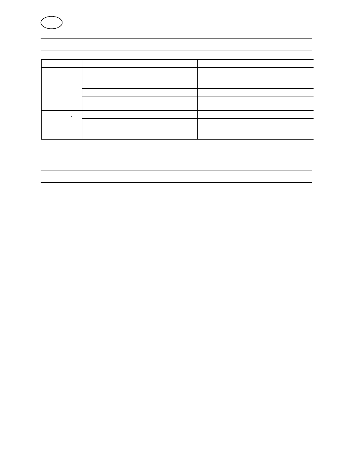
2 FAULT INDICATION
If the lamp: Cause Action
-- flashes
-- is steadily lit
The LED glows / flashes as long as the fault is detected, it can only be reset if the fault is repaired and the
machine restarted.
The control panel has lost contact with the
power unit or the wire feed unit.
The coolant flow switch has operated. S Check the cooling water flow.
No gas flow. S Check the gas valve, the hoses and
The thermal overload trips have operated. S Check to see if the air filter is clogged.
The mains voltage to the power unit is too
high.
S Check the cables. It will be necessary
to turn off the power supply to reset
the system.
connectors.
S Check the mains voltage. It will be
necessary to turn off the power supply
to reset the system.
3 REPLACMENT AND REPAIR PARTS
Note!
Supplier warranty is void if customer attempts any work on product during the warranty
period.
When ordering replacement parts, order by part number and part name, as illustrated
on the figure. Always provide the series or serial number on the unit on which the parts
will be used. The serial number is stamped on the rating plate.
3.1 Ordering
To assure proper operation, it is recommended that only genuine ESAB parts and
products be used with this equipment.
Replacement parts may be ordered from your ESAB distibutor or from:
ESAB Welding & Cuttin Products
Attn: Customer Service Dept.
P.O. Box 100545, 411 S. Ebenezer Road
Florence, SC 29501--0545
To order parts by phone, contact ESAB at 1--843--664--5540. Orders may also be faxed
to 1--800--634--7548. Be sure to indicate any special shipping instructions when
ordering replacement parts.
Refer to the Communication Guide located on the last page of this manal for a list of
customer service phone numbers.
bi01d1aa
-- 5 --
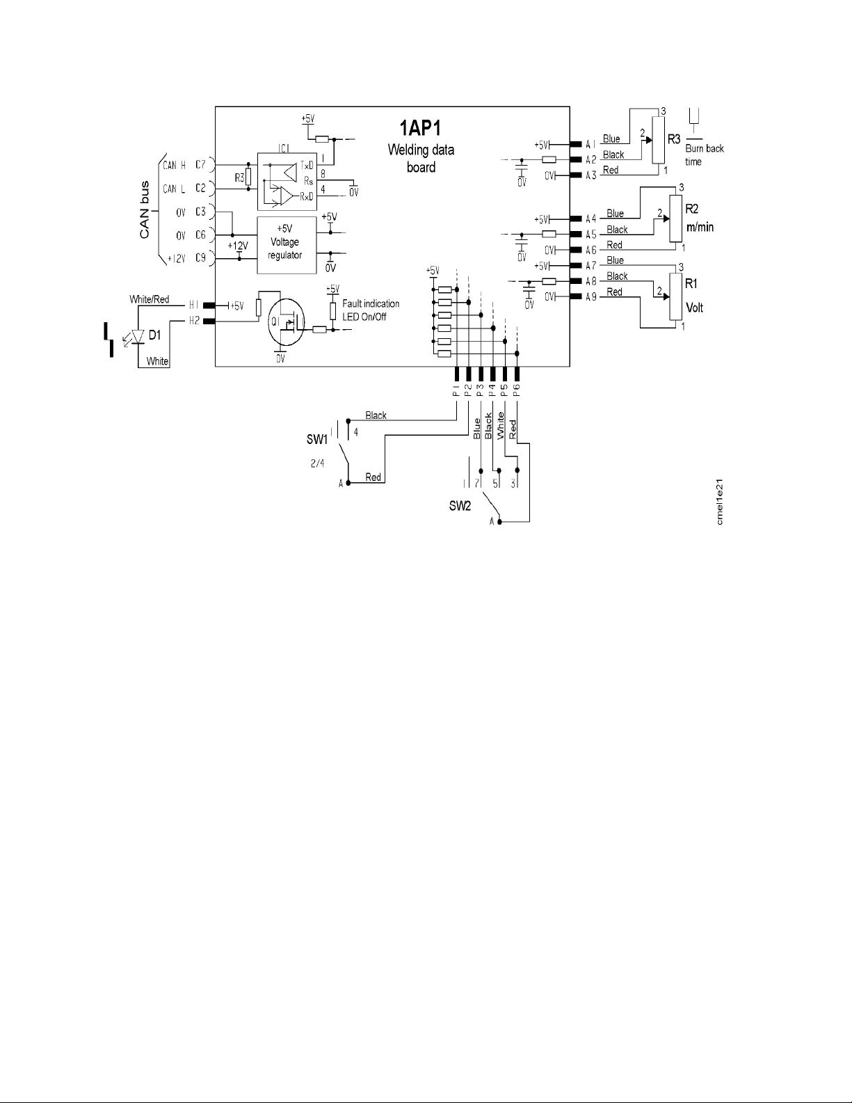
Schematic diagram
bi01e11a
-- 6 --

p
-- 7 --

ESAB Welding & Cutting Products, Florence, SC Welding Equipment
COMMUNICATION GUIDE -- CUSTOMER SERVICES
A CUSTOMER SERVICE QUESTIONS:
Telephone: (800) 362-- 7080 / Fax: (800) 634-- 7548 Hours: 8.00 AM to 7:00 PM EST
Order Entry Product Availability Pricing Order Information Returns
B ENGINEERING SERVICE:
Telephone: (834) 664-- 4416 / Fax: (800) 446-- 5693 Hours: 7.30 AM to 5:00 PM EST
Warranty Returns Authorized Repair Stations Welding Equipment Troubleshooting
C TECHNICAL SERVICE:
Telephone: (800) ESAB-- 123 / Fax: (843) 664-- 4452 Hours: 8.00 AM to 5:00 PM EST
Part Numbers Technical Applications Specifications Equi pment Recommendati ons
D LITERATURE REQUESTS:
Telephone: (843) 664-- 5562 / Fax: (843) 664-- 5548 Hours: 7.30 AM to 4:00 PM EST
E WELDING EQUIPMENT REPAIRS:
Telephone: (843) 664-- 4487 / Fax: (843) 664-- 5557 Hours: 7.30 AM to 3:30 PM EST
Repair Estimates Repair Status
F WELDING EQUIPMENT TRAINING:
Telephone: (843) 664-- 4428 / Fax: (843) 679-- 5864 Hours: 7.30 AM to 4:00 PM EST
Training Sc hool Information and Regis trations
G WELDING PROCESS ASSISTANCE:
Telephone: (800) ESAB-- 123 Hours: 7.30 AM to 4:00 PM EST
H TECHNICAL ASST. CONSUMABLES:
Telephone: (800) 933-- 7070 Hours: 7.30 AM to 5:00 PM EST
IF YOU DO NOT KNOW WHOM TO CALL
Telephone: (800) ESAB--123
Fax: (843) 664--4452
Hours: 7:30 AM to 5:00 PM EST
or
visit us on the web at http://www.esabna.com
The ESAB web site offers:
Comprehensive Product Information
Material Safety Data Sheets
Warranty Registration
Instruction Literature Download Library
Distributor Locator
Global Company Information
Press Releases
Customer Feedback & Support
ESAB Welding & Cutting Products
PO BOX 100545, Florence SC 29501--0545
 Loading...