

Page 1
MEK 2
Service manual
0740 800 094
020531
Page 2

LIST OF CONTENTS Page
READ THIS FIRST 2..................................
COMPONENT DESCRIPTION 4........................
CONNECTION DIAGRAM 5............................
DESCRIPTION OF OPERATION 6......................
1 Power supply 7.........................................
2 2--stroke / 4--stroke 8....................................
3 Start / Stop 8...........................................
4 Current relay, Creep start / Normal start 9..................
5 Motor driving / braking 10..................................
6 Tachometer input 1 1......................................
7 Burn--back time 1 1.......................................
8 Wire feed speed 1 1.......................................
9 Gas valve 12............................................
10 Activation, contactor 12...................................
11 Processor 12............................................
TECHNICAL DATA 13..................................
MAINTENANCE 13....................................
SETTING THE WIRE FEED PRESSURE 14...............
CONTROL PANEL AND CONNECTIONS 15..............
ACCESSORIES 16.....................................
SPARE PARTS LIST 17.................................
NOTES 24............................................
READ THIS FIRST
Maintenance and repair work should be performed by an experienced person, and electrical
work only by a trained electrician. Use only recommended replacement parts.
This service manual is intended for use by technicians with electrical/electronic training for
help in connection with fault--tracing and repair .
Use the connection diagram as a form of index for the d escription of operation. The circuit
board is divided into numbered blocks, which are described individually in more detail in
the description of operation. All component names in the connection diagram are listed in
the component description.
This manual contains details of all design changes that have been made up to and including
May 2002.
The MEK 2 is designed and tested in accordance with international and European
standard IEC/EN 60974--1 and EN 50199.
On completion of service or repair work, it is the responsibility of the person(s) etc.
performing the work to ensure that the product does not depart from the requirements
of the above standard.
Rights reserved to alter specifications without notice.
cmek2de1
-- 2 --
Page 3
WARNING !
STATIC ELECTRICITY can damage circuit
boards and electronic components.
SSSS Observe precautions for handling electrostatic
sensitive devices.
ESD
SSSS Use proper static--proof bags and boxes.
WARNING
ARC WELDING AND CUTTING CAN BE INJURIOUS TO YOURSELF AND OTHERS. TAKE PRECAUTIONS WHEN WELDING. ASK FOR YOUR EMPLOYER’S SAFETY PRACTICES WHICH SHOULD BE
BASED ON MANUFACTURERS’ HAZARD DATA.
ELECTRIC SHOCK -- Can kill
S Install and earth the welding unit in accordance with applicable standards.
S Do not touch live electrical parts or electrodes with bare skin, wet gloves or wet clothing.
S Insulate yourself from earth and the workpiece.
S Ensure your working stance is safe.
FUMES AND GASES -- Can be dangerous to health
S Keep your head out of the fumes.
S Use ventilation, extraction at the arc, or both, to keep fumes and gases from your breathing zone and
the general area.
ARC RAYS -- Can injure eyes and burn skin.
S Protect your eyes and body. Use the correct welding screen and filter lens and wear protective
clothing.
S Protect bystanders with suitable screens or curtains.
FIRE HAZARD
S Sparks (spatter) can cause fire. Make sure therefore that there are no inflammable materials nearby.
NOISE -- Excessive noise can damage hearing
S Protect your ears. Use ear defenders or other hearing protection.
S Warn bystanders of the risk.
MALFUNCTION -- Call for expert assistance in the event of malfunction.
READ AND UNDERSTAND THE INSTRUCTION MANUAL BEFORE INSTALLING OR OPERATING.
PROTECT YOURSELF AND OTHERS!
WARNING!
Rotating parts can cause injury, take great care
-- 3 --cmek2de1
Page 4

COMPONENT DESCRIPTION
This component description refers to the connection diagram. In the description of operation
on page 7 there is a more detailed description of the components and their function.
AP01 Main circuit board with control electronics.
C01 Capacitor 0.1 ←F 125 VAC, decoupling.
G01 Tachogenerator, incorporated in motor M01.
M01 Motor, rated voltage 24 V.
R3 Potentiometer, for setting the burn--back time.
RP01 Potentiometer, 10 kτ, for setting the wire feed speed.
SW1 Switch, 2/4--stroke changeover.
SW2 Switch, creep start ON/OFF
XP01 23--pole connector, for connection to the welding power unit.
XP02 Terminal for welding current connection from the power unit.
XS01 -- XS09 Sleeve connectors.
YV01 Solenoid valve
cmek2de1
-- 4 --
Page 5
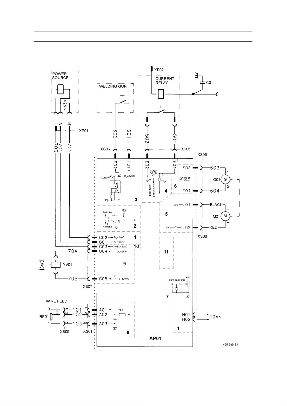
CONNECTION DIAGRAM MEK 2
The numerals 1 -- 11 refer to the description of operation.
R3
0V
cmek2e01
-- 5 --cmek2de1
Page 6
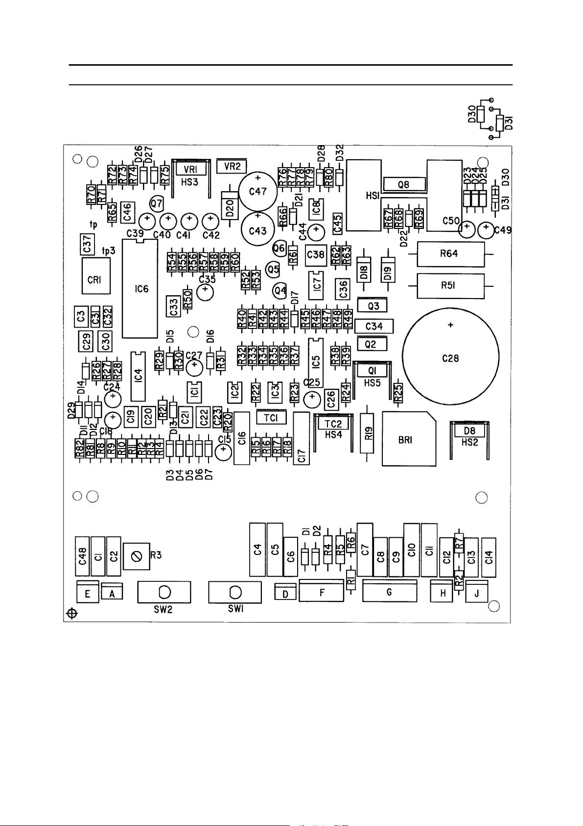
DESCRIPTION OF OPERATION
Component positions, circuit board AP01
cmek2de1
cmek2e02
-- 6 --
Page 7

Sections1to11belowrefertothediagramonpage5.
The circuit board is screened by a metal casing, connected to 0 V in the wire feed unit.
1 Power supply
The feeder obtains a 42 V supply from the control power supply tr ansformer in the
power unit via contact XP01. Its power demand at maximum load is 3.5 A.
42 V AC is used for the welding torch trigger switch and as the power supply to the
gas solenoid valve and the main contactor. In addition, 42 V is also available on
contacts H01 and H02.
cmek2e09
Rectifier BR1 rectifies the 42 V supply to 60 V. Capacitor C28 smooths the voltage,
which then supplies the wire feeder motor.
Transistor Q8 is a pre--regulator which reduces the voltage from 60 V to 20 V. Q8 is
current--limited to about 200 mA. If the 20 V supply drops below 13 V, the wire
feed unit stops.
VR1 and VR2 are 5 V and 15 V voltage regulators respectively.
-- 7 --cmek2de1
Page 8
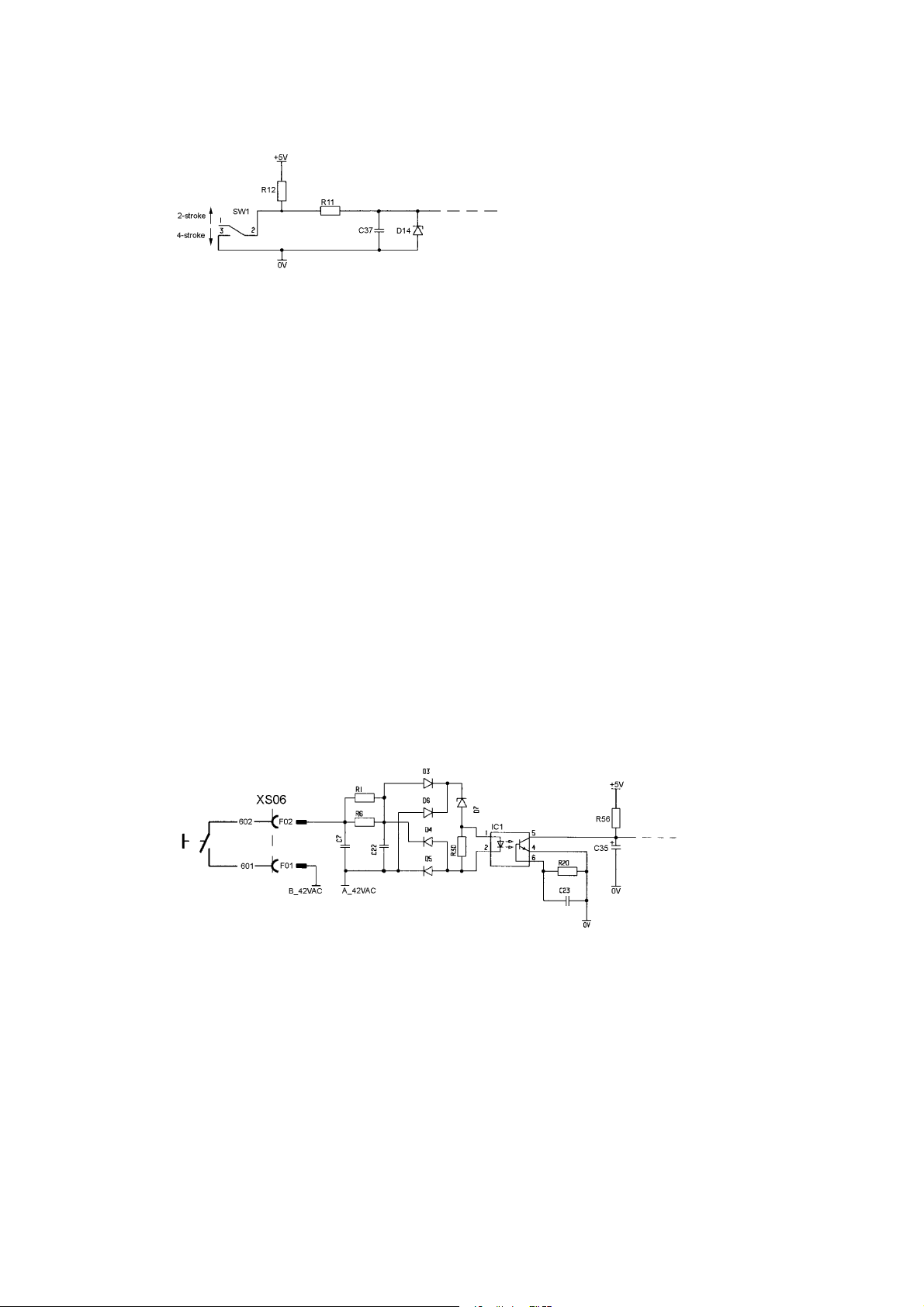
2 2--stroke / 4--stroke
2--STROKE
When SW1 is open, the unit operates in 2--stroke mode. Operating the trigger on the
welding torch starts the motor, opens the gas valve and energises the power unit
contactor.
Releasing the trigger stops the motor, de--energises the contactor and closes the gas
valve. If burn--back is in operation, welding ceases when the burn--back time has
elapsed.
4--STROKE
When SW1 is closed, the unit operates in 4--stroke mode. Operating the trigger on
the welding torch opens the gas valve: releasing the trigger then starts the motor and
energises the power unit contactor.
cmek2e08
Operating the trigger switch for a second time stops the motor and de--energises the
contactor in the power unit: releasing the switch then closes the gas solenoid valve.
If burn--back is in operation, welding ceases when the burn--back time has elapsed..
3 Start / Stop
The welding torch switch is supplied with 42 V AC. Closing the switch activates
optocoupler IC1, causing the voltage across C35 to go low.
cmek2e07
cmek2de1
-- 8 --
Page 9

4 Current relay, Creep start / Normal start
The current relay is activated when the welding current exceeds 20 A.
Creep start means that the motor runs at 1.9 m/minute until the current relay
operates, after which the speed increases to the set speed. If the current relay does
not operate within one second after starting, the m otor speed increases to the set
speed in any case.
Selector switch SW2 on the circuit board selects Creep Start On/Off. Closing the
switch on to the 0 V rail disengages creep start.
cmek2e03
-- 9 --cmek2de1
Page 10

5 Motor driving / braking
cmek2e12
DRIVING
The motor is powered from the smoothed +60 V supply. Motor speed is controlled
by pulse width modulation of transistor Q1. The pulse frequency is 12 kHz, and the
maximum on--time is 97% of the pulse cycle time. During the pulse spaces, the
motor current freewheels through diode D8.
At 24 V motor supply voltage, the wire feed rollers’ speed is 160 r/min. A wire feed
speed of 20 m/min. requires a roller speed of 212 r/min.
Resistor R19 produces a voltage drop proportional to the motor current. If the
current exceeds 7 A, IC5:2 turns off the gate pulses to Q1. When the current falls,
Q1 conducts again at the next gate pulse.
BRAKING
When the motor starts, capacitor C43 charges up via diode D28: the voltage is
limited to 15 V by zener diode D21. When the motor is to brake, the L ED in
optocoupler IC8 lights, causing the transistor in IC8 to conduct and discharge
capacitor C43 (15 V) to the gate of transistor Q3. The transistor conducts and
short--circuits the motor voltage through resistors R51 and R64, which limit the
current to about 20 A.
cmek2de1
-- 1 0 --
Page 11

6 Tachometer input
Tachometer G01 is fitted in the motor casing. Tachometer output frequency is
796 Hz for a wire feed speed of 20 meters per minute.
Comparator IC4:2 converts the sine wave signal from the tachometer to a square
wave at the same frequency.
7 Burn --back time
cmek2e06
The burn --back time is the time from when motor braking starts until the main
contactor in the power unit opens. It can be adjusted between 0 and 0.5 seconds by
potentiometer R3, which is mounted on the circuit board.
8 Wire feed speed
The wire feed speed range is from 1.9 to 20 meters per minute.
A 5 V reference voltage signal at connection A02 represents a speed of 20 m/minute.
cmek2e05
cmek2e04
-- 1 1 --cmek2de1
Page 12

9 Gas valve
The gas valve is connected to board contacts G04 and G05. The valve is energised
via triac TC1.
10 Activation, contacto r
cmek2e11
The start signal to the power unit is connected to board contact G03. The contactor
is energised via triac TC2.
11 Processor
The processor incorporates EPROM memory in which the machine’s program is
stored.
The processor monitors the wire feed speed. If the speed deviates from the set speed
by more than 1.5 m/minute for more than five seconds, wire feed will be stopped..
cmek2e10
cmek2de1
-- 1 2 --
Page 13

TECHNICAL DATA
Power supply 42 V 50 -- 60 Hz
Power requirement 150 VA
Feed speed 1.9 -- 20 m/min
Pistol connection EURO
Max. diameter of wire bobbin 300 mm
Weight 15 kg
Dimensions (l x w x h) 645 x 240 x 480 mm
WARNING
There is a risk of tipping if the MEK 4 is fitted with a counterbalance arm. Secure the
equipment, especially if used on an uneven or sloping surface.
Limit the angle of rotation of the wire feed cabinet using the straps supplied.
When moving the equipment, do NOT pull on the torch.
MAINTENANCE
Regular maintenance is important in ensuring safe and reliable operation.
S The feed unit
Clean and replace the wearing parts in the feed mechanism at regular intervals.
Do not set too high a pressure on the pressure rollers, as this can cause abnormal wear of
the pressure rollers,. the feed rollers and wire guide. Instructions for setting the wire feed
pressure are on page 14.
S The pistol
Blow the wire guide clean with compressed air at regular intervals and clean the gas
nozzle.
-- 1 3 --cmek2de1
Page 14

SETTING THE WIRE FEED PRESSURE
Start by checking that the wire can run freely through the wire liner, and then adjust the
pressure of the wire feed rollers. It is important that the pressure is not too high.
Figure 1 Figure 2
To check for correct feed pressure, feed the wire out against a piece of insulating material,
such as a piece of wood.
With the pistol held about 5 mm from the wood (Figure 1), the drive rollers should slip.
With the pistol held further away from the wood (about 50 mm, as shown in Figure 2), the
wire should continue to feed out, bending as it does so.
cmek2de1
-- 1 4 --
Page 15

CONTROL PANEL AND CONNECTIONS
1. Cooling water connections
(only --883 model).
2. Gas connection.
3. Connector for control cable from the
power unit.
4. Connector for welding current cable from
the power unit.
5. Potentiometer, wire feed speed 1.9 -- 20
meter per minute.
6. Cooling water connections to/from the
welding gun (only --883 model).
7. Strap securing points. The strap must be
used to secure the wire feed unit to the
power unit during transport.
8. Hole for fitting wire liner from the ESAB
Marathon Pac.
9. Welding gun connector.
10. Selector switch, 2/4--stroke mode.
11. Selector switch, creep start On/Off.
12. Potentiometer, burn--back time, 0 -- 0.5 seconds.
13. Brake hub.
The hub is adjusted when delivered, if readjustment is required, follow the instructions
below.
Adjust the braking power by means of the two screws (springs) inside the hub.
Turn the adjustment screws clockwise to reduce the braking power.
Adjust the brake hub so that wire is slightly slack when wire feed stops.
S = Adjustment screws
cmek0p05
-- 1 5 --cmek2de1
Page 16

ACCESSORIES
Item
no.
Ordering no. Denomination
1 469 789-- 880 Lifting eye
2 469 836-- 880
2 469 836-- 885 Connection set, 1.7 meter. When connected to LAX 380W
469 836-- 881 Connection set, 8 meter. When connected to LAX 320/380
469 836-- 886 Connection set, 8 meter. When connected to LAX 380W
4 469 786-- 880 T rolley
5 156 654-- 883 Guide pin (included in LAX)
6 469 792-- 881 Counter balance device and mast
7 469 967-- 880 W ater connection set
8 455 410-- 001 Adapter for 5 kg bobbin
9 0156 746 880 Mast
10 0456 693 880 Counter balance device, sprung coil
11 0457 341 880 Hose reinforcement bracket
Connection set, 1.7 meter. When connected to LAX
320/380
cmek2de1
cmek2p02
-- 1 6 --
Page 17

MEK
2E
dit
ion
Spare parts list
020531
Valid for serial no. 510 --xxx--xxxx to serial no. 826--xxx--xxxx
Ordering numbers for MEK 2
0455 590 881 MEK 2 Without water connection
0455 590 883 MEK 2 With water connection
Spare parts are to be ordered through the nearest ESAB agency as per the list on the back of the
cover. Kindly indicate type of unit, serial number, denominations and ordering numbers according to
the spare parts list.
Maintenance and repair work should be performed by an experienced person, and electrical work only
by a trained electrician. Use only recommended spare parts.
-- 1 7 --bm17s11a
Page 18

MEK
2E
dit
ion
Item
Qty Ordering no. Denomination Notes
101a 1 0455 693 001 Cover
101b 1 0456 352 001 Plate With text
102 1 0467 176 001 Handle
103 4 0192 230 105 Cover
104 1 0192 230 112 Cover
105 1 0469 959 001 Side cover
106 4 0467 695 001 Rubber foot
107 2 0469 823 001 Hook
108 2 0369 561 002 Clamp
109 2 0369 561 001 Lock
110 1 0469 960 001 Side cover
111 1 0192 562 104 Cage nut M5
020531
112a -- Chassis Replaced by item 112b
112b 1 0469 779 880 Chassis New design, fits all versions of MEK 4
113 1 0146 967 881 Brake hub
114 1 0416 236 001 Plate
115 1 0192 230 104 Cover
-- 1 8 --bm17s11a
Page 19

MEK
2E
dit
ion
020531
-- 1 9 --bm17s11a
Page 20

MEK
2E
dit
ion
020531
C = component designation in the circuit diagram
Item Qty Ordering no. Denomination Notes C
201 1 0321 475 882 Knob
202 1 0469 776 001 Cover
203 1 0193 260 092 Cover For 3--pole connector
204 1 0193 260 062 Connector 3-- pole XS07, XS08,
205 1 0191 870 616 Potentiometer 10 kτ RP01, RP02,
206 1 0368 543 005 Pin socket 23-- pole XP01
14 0323 945 004 Pin
XS09, XS10
RP03, RP04
207 1 0190 315 106 Hose L=2x0.65metre, D=16/9.5mm reinforced PVC.
208a 1 0365 803 008 Quick connector Female, red
1 0365 803 009 Quick connector Female, blue
-- -- 0365 803 001 Quick connector Male
208b 1 0365 803 008 Quick connector Female, red Beforeser.no. ... 649 ....
1 0365 803 009 Quick connector Female, blue Beforeser.no. ... 649 ....
208b 1 0365 803 011 Quick connector Female, red Fromser.no. ... 649 ....
1 0365 803 012 Quick connector Female, blue Fromser.no. ... 649 ....
-- -- 0365 803 013 Quick connector Male Fromser.no. ... 649 ....
209 1 0367 149 001 Quick connector Male, the nut is not included
1 Nut M10
-- 0365 803 002 Quick connector Female
210 1 0456 496 001 Hose L=0.33metre, D=9/5mm, reinforced PVC.
211 1 0193 054 002 Solenoid valve YV01
212 1 0456 496 001 Hose L=0.22metre, D=9/5mm, reinforced PVC
213 1 0160 609 881 Welding current connector XP02
214 1 0455 599 880 Busbar With insulation.
215 1 0192 915 013 Capacitor PME 271 0.1 ←F 250 V, without cable lugs C01
216 1 Screw M10x20
217 1 Spring washer ⊘ 20/10.2x1.1
218 1 Washer ⊘ 24/13x2
To be ordered per metre.
To be ordered per metre.
To be ordered per metre.
The picture on the opposite page does not show
the real shape of the busbar.
219 1 0455 517 001 Cover (bottom box) From ser. no. 826 . . . . . . Length = 317mm
220 1 0486 283 880 Circuit board AP01
221 1 0455 518 001 Box (top box) From ser. no. 826 . . . . . . Length = 317mm
222 1 0455 519 001 Cover Fromser.no. 514 ... ....
223 1 0193 260 062 Connector 3-- pole XS01
1 0193 260 091 Cover For 3--pole connector
2 0193 260 150 Connector 2--pole XS05, XS08
2 0193 260 180 Cover For 2--pole connector
1 0193 260 152 Connector 4--pole XS06
1 0193 260 182 Cover For 4--pole connector
1 0193 260 153 Connector 5--pole XS07
1 0193 260 183 Cover For 5--pole connector
224 3 0455 661 019 Plastic rivet Fromser.no.514 ... .... to514718 ....
225 3 0193 517 342 Screw Plastic Fromser.no. 514718 ....
226 3 0194 019 001 Spacer Plastic Fromser.no. 514718 ....
232 1 0458 918 880 Front flange with PC board Current relay
When a cover with another length is replaced
also item 221 must be replaced.
When a box with another length is replaced also
item 219 must be replaced. With this box items
228, 225 and 226 must be used.
-- 2 0 --bm17s11a
Page 21

MEK
2E
dit
ion
020531
-- 2 1 --bm17s11a
Page 22

MEK
2E
dit
ion
020531
C = component designation in the circuit diagram
Item Qty Ordering no. Denomination Notes C
-- -- 0455 890 881 Feed unit Complete, contains items 301 -- 332
300 1 0469 833 880 Pressure arm (W) Complete, contains items 301 -- 305
301 1 0455 053 880 Geared adapter (W)
302 1 0369 728 001 Pressure roller (W)
0466 262 001 Pressure roller (W) (A) Knurled
303 1 Locking washer SGA D8
304 1 Holder
305 1 Shaft
306 1 0455 896 001 Spring
308 1 0455 597 001 Drive unit With tachometer M01, G01
309 1 0215 701 007 Locking washer Included in item 308
310 1 0191 496 114 Key Included in item 308
311 1 0466 074 001 Inlet nozzle (W)
312 1 0367 528 001 Pin bolt
313 1 0368 749 880 Pressure transducer
314 2 0368 750 001 Insulating sleeve
315a 1 0455 894 001 Insert tube (W) (A) For Al wire, must be used together with item
315b 1 0455 889 001 Insert tube (W) Steel, must be used together with item 316b
316a 1 0455 885 001 Outlet nozzle (W) (A) Must be used together with item 315a
316b 1 0455 886 001 Outlet nozzle (W) Must be used together with item 315b
317 1 0455 882 001 Current sleeve
318 1 0455 883 001 Spacer sleeve ⊘ 16/8.2x0.9
319 1 Washer ⊘ 16/8.4x1.5
320 1 Screw M8x20
321 1 0455 881 001 Protection plate
322 1 0215 201 202 O--ring
323 1 0455 898 001 Screw (M5x12)
324 1 Screw M4x12
325 2 Screw M3x16
326 1 0193 104 002 Washer
327 1 0369 557 001 Feed roller (W) (A) (V)For ⊘ 0.6 -- 0.8 mm Fe, Ss and cored wire
1 0369 557 002 Feed roller (W) (A) (V)For ⊘ 0.8 -- 1.0 mm Fe, Ss and cored wire
1 0369 557 003 Feed roller (W) (V)For ⊘ 1.0 -- 1.2 mm Fe, Ss and cored wire
1 0369 557 007 Feed roller (W) (A) (V)For ⊘ 1.2 -- 1.6 mm Fe, Ss and cored wire
1 0369 557 010 Feed roller (W) (A) (V)For ⊘ 1.2 mm x 2 Fe, Ss and cored wire
1 0369 557 013 Feed roller (W) (A) (V)For ⊘ 1.4 --1.6 mm Fe, Ss and cored wire
1 0369 557 004 Feed roller (W) (A) (K)(V) For ⊘1.0 -- 1.2 / 1.4 -- 1.6 mm cored wire
1 0369 557 005 Feed roller (W) (A) (K)(V) For ⊘1.4--1.6 / (2.0-- 2.4) mm cored wire
1 0369 557 006 Feed roller (W) (A) (U) For ⊘ 1.0 -- 1.2 mm Al wire
1 0369 557 008 Feed roller (W) (A) (U) For ⊘ 1.6 mm Al wire
1 0369 557 011 Feed roller (W) (A) (U) For ⊘ 0,8 -- 0,9 mm Al wire
328 1 0369 716 001 Geared adapter (W)
316a
Delivered from machine no. XXX 647 XXX
Delivered from machine no. XXX 647 XXX
329 1 0455 893 001 Shaft
330 1 0455 884 001 Gear housing
331 3 Screw M6x16
332 1 0332 351 013 Drive shaft with pinion Included in item 308
(W) = wear part (A) = accessory (K) = knurled rollers (V) = V--groove (U) = U--groove
-- 2 2 --bm17s11a
Page 23

MEK
2E
dit
ion
020531
-- 2 3 --bm17s11a
Page 24

NOTES
-- 2 4 --notes
Page 25

-- 2 5 --notes
Page 26

ESAB subsidiaries and representative offices
Europe
AUSTRIA
ESAB Ges.m.b.H
Vienna--Liesing
Tel: +43 1 888 25 11
Fax: +43 1 888 25 11 85
BELGIUM
S.A. ESAB N.V.
Brussels
Tel: +32 2 745 11 00
Fax: +32 2 726 80 05
THE CZECH REPUBLIC
ESAB VAMBERK s.r.o.
Prague
Tel: +420 2 819 40 885
Fax: +420 2 819 40 120
DENMARK
Aktieselskabet ESAB
Copenhagen--Valby
Tel:+4536300111
Fax:+4536304003
FINLAND
ESAB Oy
Helsinki
Tel: +358 9 547 761
Fax: +358 9 547 77 71
FRANCE
ESAB France S.A.
Cergy Pontoise
Tel:+33130755500
Fax:+33130755524
GERMANY
ESAB GmbH
Solingen
Tel: +49 212 298 0
Fax: +49 212 298 204
GREAT BRITAIN
ESAB Group (UK) Ltd
Waltham Cross
Tel: +44 1992 76 85 15
Fax: +44 1992 71 58 03
ESAB Automation Ltd
Andover
Tel: +44 1264 33 22 33
Fax: +44 1264 33 20 74
HUNGARY
ESAB Kft
Budapest
Tel:+3612044182
Fax:+3612044186
ITALY
ESAB Saldatura S.p.A.
Mesero (Mi)
Tel:+3902979681
Fax:+390297289181
THE NETHERLANDS
ESAB Nederland B.V.
Utrecht
Tel: +31 30 248 59 22
Fax: +31 30 248 52 60
NORWAY
AS ESAB
Larvik
Tel:+4733121000
Fax:+4733115203
POLAND
ESAB Sp.z.o.o
Warszaw
Tel: +48 22 813 99 63
Fax: +48 22 813 98 81
PORTUGAL
ESAB Lda
Lisbon
Tel: +351 1 837 1527
Fax: +351 1 859 1277
SLOVAKIA
ESAB Slovakia s.r.o.
Bratislava
Tel:+421744882426
Fax:+421744888741
SPAIN
ESAB Ibérica S.A.
Alcobendas (Madrid)
Tel: +34 91 623 11 00
Fax: +34 91 661 51 83
SWEDEN
ESAB Sverige AB
Gothenburg
Tel:+4631509500
Fax:+4631509222
ESAB International AB
Gothenburg
Tel:+4631509000
Fax:+4631509360
SWITZERLAND
ESAB AG
Dietikon
Tel: +41 1 741 25 25
Fax: +41 1 740 30 55
North and South America
ARGENTINA
CONARCO
Buenos Aires
Tel: +54 11 4 753 4039
Fax: +54 11 4 753 6313
BRAZIL
ESAB S.A.
Contagem--MG
Tel: +55 31 333 43 33
Fax: +55 31 361 31 51
CANADA
ESAB Group Canada Inc.
Missisauga, Ontario
Tel: +1 905 670 02 20
Fax: +1 905 670 48 79
MEXICO
ESAB Mexico S.A.
Monterrey
Tel: +52 8 350 5959
Fax: +52 8 350 7554
USA
ESAB Welding & Cutting Products
Florence, SC
Tel: +1 843 669 44 11
Fax: +1 843 664 44 58
Asia/Pacific
AUSTRALIA
ESAB Australia Pty Ltd
Ermington
Tel: +61 2 9647 1232
Fax: +61 2 9748 1685
CHINA
Shanghai ESAB A/P
Shanghai
Tel: +86 21 6539 7124
Fax: +86 21 6543 6622
INDIA
ESAB India Ltd
Calcutta
Tel: +91 33 478 45 17
Fax: +91 33 468 18 80
INDONESIA
P.T. Esabindo Pratama
Jakarta
Tel: +62 21 460 01 88
Fax: +62 21 461 29 29
MALAYSIA
ESAB (Malaysia) Snd Bhd
Selangor
Tel: +60 3 703 36 15
Fax: +60 3 703 35 52
SINGAPORE
ESAB Singapore Pte Ltd
Singapore
Tel: +65 861 43 22
Fax: +65 861 31 95
ESAB Asia/Pacific Pte Ltd
Singapore
Tel: +65 861 74 42
Fax: +65 863 08 39
SOUTH KOREA
ESAB SeAH Corporation
Kyung--Nam
Tel: +82 551 289 81 11
Fax: +82 551 289 88 63
UNITED ARAB EMIRATES
ESAB Middle East
Dubai
Tel: +971 4 338 88 29
Fax: +971 4 338 87 29
Representative offices
BULGARIA
ESAB Representative Office
Sofia
Tel/Fax: +359 2 974 42 88
EGYPT
ESAB Egypt
Dokki--Cairo
Tel: +20 2 390 96 69
Fax: +20 2 393 32 13
ROMANIA
ESAB Representative Office
Bucharest
Tel/Fax: +40 1 322 36 74
RUSSIA--CIS
ESAB Representative Office
Moscow
Tel: +7 095 937 98 20
Fax: +7 095 937 95 80
ESAB Representative Office
St Petersburg
Tel: +7 812 325 43 62
Fax: +7 812 325 66 85
Distributors
For addresses and phone
numbers to our distributors in
other countries, please visit our
home page
www.esab.com
ESAB AB
SE-- 695 81 LAXÅ
SWEDEN
Phone +46 584 81 000
Fax +46 584 123 08
www.esab.com
020314
 Loading...