

Page 1

GB
Caddyt
TA33 AC/DC
Instruction manual
Valid from program version 1.020460 226 074 GB 081124
Page 2

1 INTRODUCTION 3...................................................
1.1 Control panel 3.............................................................
2 TIG WELDING 4.....................................................
2.1 Settings 4..................................................................
2.2 Symbol and Function explanations 5...........................................
2.3 Hidden TIG functions 7......................................................
3 MMA WELDING 8....................................................
3.1 Settings 8..................................................................
3.2 Symbol and Function explanations 8...........................................
4 FAULT CODES 9.....................................................
4.1 List of fault codes 9..........................................................
4.2 Fault code descriptions 10.....................................................
5 ORDERING SPARE PARTS 11..........................................
ORDERING NUMBER 12.................................................
Rights reserved to alter specifications without notice.
TOCe
-- 2 --
Page 3

GB
1 INTRODUCTION
The manual describes the use of TA33 AC/DC control panel.
For general information about operation see instruction manual for the power source.
When mains power is supplied the unit runs a self diagnosis of the
LEDs and the display, the program version is displayed and in this
example the program version is 0.18.
Instruction manuals in other languages can be downloaded from the website,
www.esab.com.
1.1 Control panel
Knob for setting data (current, voltage, material thickness or seconds)
Display
Choice of welding method TIG or MMA
Choice of TIG / MMA welding with alternating current , TIG / MMA welding
with direct current
Choice of HF start or LiftArct
Choice of 2--stroke or 4--stroke
bi17d1ea
-- 3 --
Page 4

GB
Setting from panel and connecting remote control unit
Display of VRD function (reduced open-- circuit voltage) is active or inactive.
NOTE! This function works for power sources where it is implemented.
Choice of current indication (A) or seconds (s) during welding, in the display.
Indication of which unit of measurement is used (mm or inch).
Choice of parameter for material thickness slope down or gas post flow.
Indication of selected material thickness (mm/inch).
Indication of selected slope down time (s).
Indication of selected gas post flow time (s).
2 TIG WELDING
2.1 Settings
TIG AC/DC
Function Setting range In steps of Default value
HF / LiftArc t
2/4--stroke
Gas pre flow time
Material thickness1) 0.1 -- 7.3 mm 0.1 mm 2mm
Slope up--time1) 0--9.9s 0.1 s 0.0 s
Slope down time 0--10s 0.1 s 1.0 s
Gas post flow time 0--25s 0.1 s 10.0 s
Current 4 -- 220 A 1A 60 A
Active panel OFF or ON -- ON
Remote control unit OFF or ON -- OFF
Min current 0--99% -- 30%
1)
These functions are hidden TIG functions, see description point 2.3.
2)
These functions cannot be changed while welding is in progress
2)
2)
1)
HF or LiftArct -- LiftArct
2strokeor4stroke -- 2stroke
0--5s 0.1 s 0.5 s
bi17d1ea
-- 4 --
Page 5

GB
2.2 Symbol and Function explanations
VRD (Voltage Reducing Device)
The VRD function ensures that the open--circuit voltage does not exceed 35 V when
welding is not being carried out. T his is indicated by a lit VRD LED.
The VRD function is blocked when the system senses that welding has started.
If the VRD function is activated and the open--circuit voltage exceeds the 35 V limit,
this is indicated by an error message (16) appearing in the display and welding
cannot be started whilst the error message is displayed.
The VRD function is activated in power sources delivered with Australian mains plug.
For other power sources contact an authorised ESAB service technician to activate
the function.
Note! The VRD function works for power sources where it is implemented.
TIG welding
TIG welding melts the metal of the workpiece, using an arc struck from a tungsten
electrode, which does not itself melt. The weld pool and the electrode are protected by
shielding gas.
Alternating current
The advantages of alternating current are reduced risk of magnetic arc blow and
good oxide break--up capacity when welding aluminium.
Direct current
A higher current produces a wider weld pool, with better penetration into the
workpiece.
Slope up
The slope up function means that, when the TIG arc strikes, the current rises slowly
to the set value. This provides ‘gentler’ heating of the electrode, and gives the welder
a chance to position the electrode properly before the set welding current is reached.
Slope down
TIG welding uses “slope down”, by which the current falls ’slowly’ over a controlled
time, to avoid craters and/or cracks. when a weld is finished.
Gas post--flow
This controls the time during which shielding gas flows after the arc is extinguished.
HF
The HF function strikes the arc by means of a spark from the electrode to the
workpiece as the electrode is brought closer to the workpiece.
bi17d1ea
-- 5 --
Page 6
GB
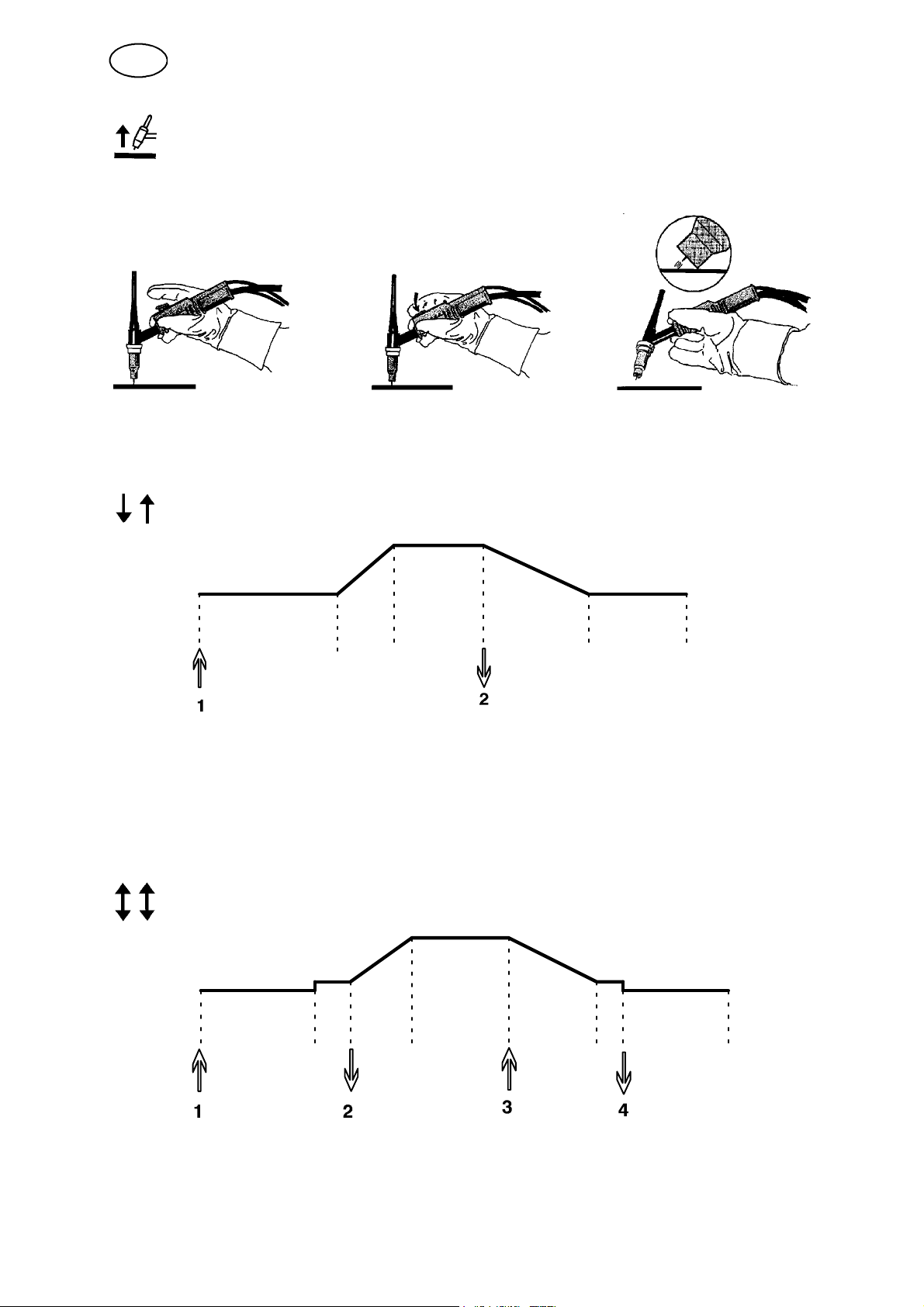
LiftArct
The LiftArct function strikes the arc when the electrode is brought into contact with
the workpiece and then lifted away from it.
Striking t he arc with LiftArct. Step 1: the electrode is touched on to the workpiece. Step 2: the trigger
switch is pressed, and a low current starts to flow. Step 3: the welder lifts the electrode from the
workpiece: the arc strikes, and the current rises automatically to the set value.
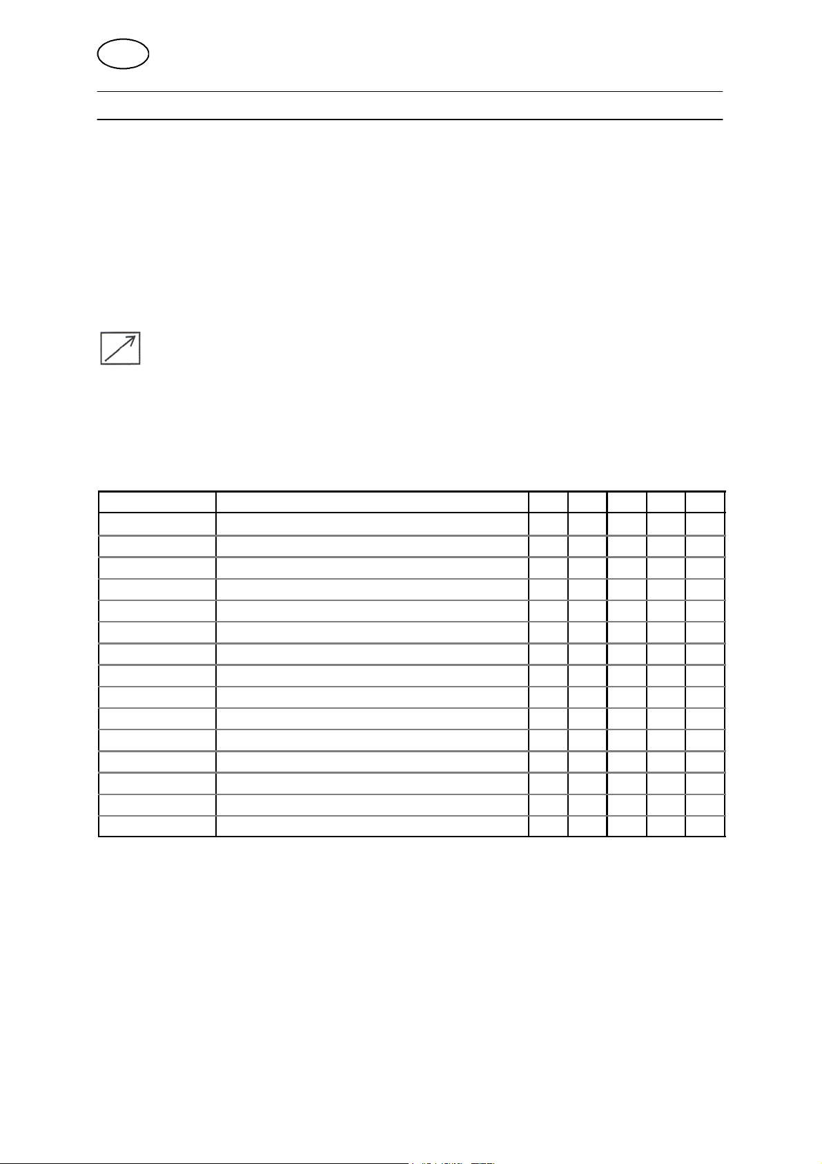
2stroke
Gas pre--flow Slope
up
Functions when using 2 stroke control of the welding torch.
Slope down Gas post--
flow
In the 2 stroke control mode, pressing the TIG torch trigger switch (1) starts gas
pre--flow (if used) and strikes the arc. The current rises to the set value (as controlled
by the slope up function, if in operation). Releasing the trigger switch (2) reduces the
current (or starts slope down if in operation) and extinguishes the arc. Gas post--flow
follows if it is in operation.
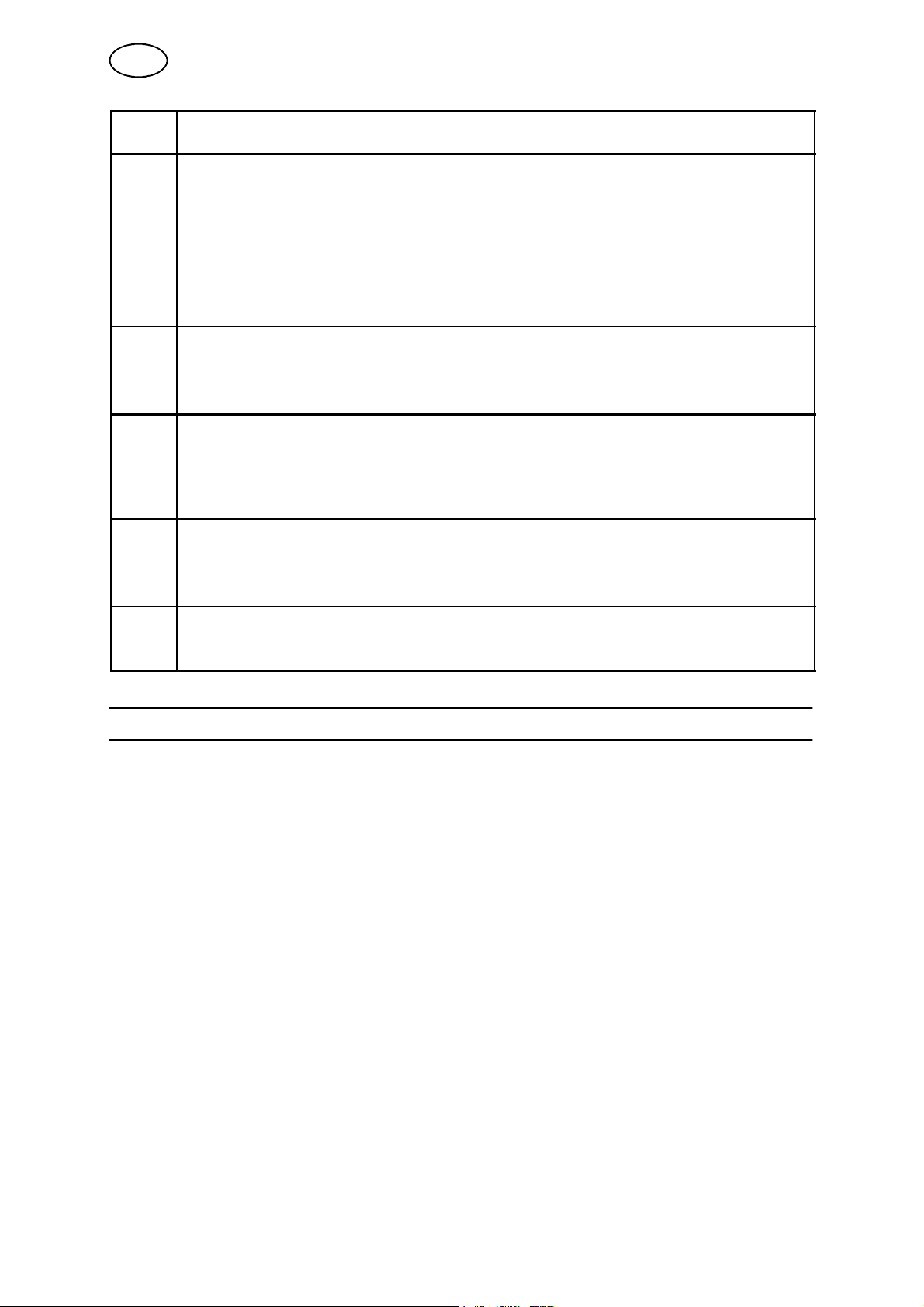
4stroke
Gas pre--flow Slope
up
Slope down Gas post--
flow
Functions when using 4 stroke control of the welding torch.
In the 4 stroke control mode, pressing the trigger switch (1) starts gas pre--flow ( if
used). At the end of the gas pre--flow time, the current rises to the pilot current (a few
bi17d1ea
-- 6 --
Page 7

GB
ampere), and the arc is struck. Releasing the trigger switch (2) increases the current
to the set value (with slope up, if in use). When the trigger switch is pressed in (3)
the current returns to the set pilot current (with ”slope down” if in use). When the
trigger switch is released again (4) the arc is extinguished and any gas post flow
occurs.
Active panel
Settings are made from the control panel.
Remote control unit
Settings are made from the remote control unit.
The remote control unit must be connected to the remote control unit socket on the
machine before activation. When the remote control unit is activated the panel is
inactive.
2.3 Hidden TIG functions
There are hidden functions in the control panel.
To access the functions, press for 5 seconds. T he display shows a letter and
a value. Select function by pressing the right arrow. The knob is used to change the
value of the selected function.
Function Settings
A = gas pre--flow 0--5s
b = slope up 0--9,9
C = unit of measurement 0 = inch, 1 = mm
I = min current 0 -- 99%
To leave hidden functions, press
Gas pre--flow
for 5 seconds.
This controls the time during which shielding gas flows before the arc is struck.
Min current
Used to set the minimum current for the remote control T1 Foot CAN.
If the max current is 100 A and the min current is to be 50 A, set the concealed
function min current to 50%.
If the max current is 100 A and the min current is to be 90 A, set the min current to
90%.
bi17d1ea
-- 7 --
Page 8

GB
3 MMA WELDING
3.1 Settings
Function Setting range In steps of Default value
Current 16 -- max A
Active panel OFF or ON -- ON
Remote control unit OFF or ON -- OFF
*)
The setting range is dependent on the power source used.
3.2 Symbol and Function explanations
VRD (Voltage Reducing Device)
The VRD function ensures that the open--circuit voltage does not exceed 35 V when
welding is not being carried out. T his is indicated by a lit VRD LED.
*)
1A 100 A
The VRD function is blocked when the system senses that welding has started.
If the VRD function is activated and the open--circuit voltage exceeds the 35 V limit,
this is indicated by an error message (16) appearing in the display and welding
cannot be started whilst the error message is displayed.
The VRD function is activated in power sources delivered with Australian mains plug.
For other power sources contact an authorised ESAB service technician to activate
the function.
Note! The VRD function works for power sources where it is implemented.
MMA welding
MMA welding may also be referred to as welding with coated electrodes. Striking the
arc melts the electrode, and its coating forms protective slag.
During MMA welding, it is possible to weld with reversed polarity.
Select MMA welding and then press .
Active panel
Settings are made from the control panel.
Remote control unit
Settings are made from the remote control unit.
The remote control unit must be connected to the remote control unit socket on the
machine before activation. When the remote control unit is activated the panel is
inactive.
bi17d1ea
-- 8 --
Page 9
GB
4 FAULT CODES
The fault code is used to indicate that a fault has occurred in the equipment. It is
indicated in the display by an E followed by a fault code number.
A unit number is displayed to indicate which unit has generated the fault.
Fault code numbers and unit numbers are shown alternately.
If several faults have been detected only the code for the last occurring fault is
displayed. Press any function button or turn the knob to remove the fault indication
from the display.
NOTE! If the remote control is activated, deactivate the remote control by pressing
to remove the fault indication.
4.1 List of fault codes
U0 = welding data unit U2 = power source U5 = AC--unit
U1 = cooling unit U4 = remote control unit
Fault code Description U0 U1 U2 U4 U5
4 Power supply 5 V x x
6 High temperature x x x
7 High temperature x
8 Supply voltage 24V/15V x x
9 Supply voltage --11V x x
12 Communication error (warning) x x x x
14 Communication error (bus off) x
15 Messages lost x
16 High open--circuit voltage VRD x
19 Memory error x
20 High inductance in the welding circuit x
25 Lost contact with AC--unit x
26 Program operating fault x
29 No cooling water flow x x
41 Lost contact with the cooling unit x
bi17d1ea
-- 9 --
Page 10

GB
4.2 Fault code descriptions
Fault
code
E4
U0
U5
E6
U1
U2
U5
E7U5High temperature
E8
U1
U5
E9
U1
U5
E12
U0
U1
U4
U5
E14U0Communication error (bus off)
E15U0Communication problems (lost message)
E16U2High open--circuit voltage VRD
E19U0Memory error
Description
5 V power supply low
The power supply voltage is too low.
The current welding process is stopped and starting is prevented.
Action: Turn off the mains power supply to reset the unit. Send for a service technician if
the fault persists.
High temperature
The thermal overload cut--out has tripped.
The current welding process is stopped and cannot be restarted until the temperature has
fallen.
Action: Check that the cooling air inlets or outlets are not blocked or clogged with dirt.
Check the duty cycle being used, to make sure that the equipment is not being overloaded.
Faulty 24 V/15 V supply voltage
The supply voltage is too high or too low.
The current welding process is stopped and starting is prevented.
Action: Turn off the mains power supply to reset the unit. Send for a service technician if
the fault persists.
Faulty --11 V supply voltage
The supply voltage is too high or too low.
The current welding process is stopped and starting is prevented.
Action: Turn off the mains power supply to reset the unit. Send for a service technician if
the fault persists.
Communication error (warning)
Less serious interference on the CAN bus.
Action: Check that there are no faulty units connected on the CAN bus. Check the cables.
Send for a service technician if the fault persists.
Serious interference on the CAN bus.
Action: Check that there are no faulty units connected on the CAN bus. Check the cables.
Send for a service technician if the fault persists.
The system’s CAN bus has been overloaded.
Action: Send for a service technician if the fault persists.
Open circuit voltage has been too high.
Action: Turn off the mains power supply to reset the unit. Send for a service technician if
the fault persists.
Content of existing memory is incorrect. Basic data will be used.
Action: Turn off the mains power supply to reset the unit. Send for a service technician if
the fault persists.
bi17d1ea
-- 1 0 --
Page 11
GB
Fault
code
E20U2High inductance in the welding circuit
E25U0Lost contact with AC--unit
E26U0Program operating fault
E29
U0
U1
E41U0Lost contact with the cooling unit
Description
The power source cannot produce the desired current because the measured inductance
in the welding circuit is too high. The fault indication is reset if the inductance reading
receives a sufficiently low value at weld start. Resetting can also be achieved by turning off
the power.
Action: Use shorter welding cables and ensure that the cables are not coiled up. Place the
welding cable and connector cable next to each other. If possible, the inductance can be
reduced by welding with a shorter arc
Send for a service technician if the fault persists.
The control panel has lost contact with the AC unit.
The current welding process stops.
Action: Send for a service technician if the fault persists.
Something has prevented the processor from performing its normal tasks in the program.
The program restarts automatically. The current welding process will be stopped. This fault
does not disable any functions.
Action: Send for a service technician if the fault persists.
No cooling water flow
The flow monitor switch has tripped.
The current welding process is stopped and starting is prevented.
Action: Check the cooling water circuit and the pump.
The welding data unit has lost contact with the cooling unit. The welding process stops.
Action: Check the wiring. If the fault persists, send for a service technician.
5 ORDERING SPARE PARTS
Spare parts may be ordered through your nearest ESAB dealer, see the last page of
this publication.
bi17d1ea
-- 11 --
Page 12

TA33 AC/DC
Ordering number
Ordering no. Denomination
0460 250 881 Control panel Caddyt TA33 AC/DC
0460 226 070 Instruction manual SE
0460 226 071 Instruction manual DK
0460 226 072 Instruction manual NO
0460 226 073 Instruction manual FI
0460 226 074 Instruction manual GB
0460 226 075 Instruction manual DE
0460 226 076 Instruction manual FR
0460 226 077 Instruction manual NL
0460 226 078 Instruction manual ES
0460 226 079 Instruction manual IT
0460 226 080 Instruction manual PT
0460 226 081 Instruction manual GR
0460 226 082 Instruction manual PL
0460 226 083 Instruction manual HU
0460 226 084 Instruction manual CZ
0460 226 085 Instruction manual SK
0460 226 089 Instruction manual EE
0460 226 090 Instruction manual LV
0460 226 091 Instruction manual SL
0460 226 092 Instruction manual LT
0460 226 027 Instruction manual RU, GB
0459 839 014 Spare parts list
Instruction manuals and the spare parts list are available on the Internet at www.esab.com
bi17o
-- 1 2 -Edition 081124
Page 13

NOTES
n1
-- 1 3 --
Page 14

n1
-- 1 4 --
Page 15

n1
-- 1 5 --
Page 16
ESAB subsidiaries and representative offices
Europe
AUSTRIA
ESAB Ges.m.b.H
Vienna--Liesing
Tel: +43 1 888 25 11
Fax: +43 1 888 25 11 85
BELGIUM
S.A. ESAB N.V.
Brussels
Tel: +32 2 745 11 00
Fax: +32 2 745 11 28
THE CZECH REPUBLIC
ESAB VAMBERK s.r.o.
Vamberk
Tel: +420 2 819 40 885
Fax: +420 2 819 40 120
DENMARK
Aktieselskabet ESAB
Herlev
Tel:+4536300111
Fax:+4536304003
FINLAND
ESAB Oy
Helsinki
Tel: +358 9 547 761
Fax: +358 9 547 77 71
FRANCE
ESAB France S.A.
Cergy Pontoise
Tel:+33130755500
Fax:+33130755524
GERMANY
ESAB GmbH
Solingen
Tel: +49 212 298 0
Fax: +49 212 298 218
GREAT BRITAIN
ESAB Group (UK) Ltd
Waltham Cross
Tel: +44 1992 76 85 15
Fax: +44 1992 71 58 03
ESAB Automation Ltd
Andover
Tel: +44 1264 33 22 33
Fax: +44 1264 33 20 74
HUNGARY
ESAB Kft
Budapest
Tel:+3612044182
Fax:+3612044186
ITALY
ESAB Saldatura S.p.A.
Mesero (Mi)
Tel:+3902979681
Fax:+390297289181
THE NETHERLANDS
ESAB Nederland B.V.
Amersfoort
Tel: +31 33 422 35 55
Fax: +31 33 422 35 44
NORWAY
AS ESAB
Larvik
Tel:+4733121000
Fax:+4733115203
POLAND
ESAB Sp.zo.o.
Katowice
Tel: +48 32 351 11 00
Fax: +48 32 351 11 20
PORTUGAL
ESAB Lda
Lisbon
Tel: +351 8 310 960
Fax: +351 1 859 1277
SLOVAKIA
ESAB Slovakia s.r.o.
Bratislava
Tel:+421744882426
Fax:+421744888741
SPAIN
ESAB Ibérica S.A.
Alcalá de Henares (MADRID)
Tel: +34 91 878 3600
Fax: +34 91 802 3461
SWEDEN
ESAB Sverige AB
Gothenburg
Tel:+4631509500
Fax:+4631509222
ESAB international AB
Gothenburg
Tel:+4631509000
Fax:+4631509360
SWITZERLAND
ESAB AG
Dietikon
Tel: +41 1 741 25 25
Fax: +41 1 740 30 55
North and South America
ARGENTINA
CONARCO
Buenos Aires
Tel: +54 11 4 753 4039
Fax: +54 11 4 753 6313
BRAZIL
ESAB S.A.
Contagem--MG
Tel: +55 31 2191 4333
Fax: +55 31 2191 4440
CANADA
ESAB Group Canada Inc.
Missisauga, Ontario
Tel: +1 905 670 02 20
Fax: +1 905 670 48 79
MEXICO
ESAB Mexico S.A.
Monterrey
Tel: +52 8 350 5959
Fax: +52 8 350 7554
USA
ESAB Welding & Cutting Products
Florence, SC
Tel: +1 843 669 44 11
Fax: +1 843 664 57 48
Asia/Pacific
CHINA
Shanghai ESAB A/P
Shanghai
Tel: +86 21 2326 3000
Fax: +86 21 6566 6622
INDIA
ESAB India Ltd
Calcutta
Tel: +91 33 478 45 17
Fax: +91 33 468 18 80
INDONESIA
P.T. ESABindo Pratama
Jakarta
Tel: +62 21 460 0188
Fax: +62 21 461 2929
JAPAN
ESAB Japan
Tokyo
Tel: +81 45 670 7073
Fax: +81 45 670 7001
MALAYSIA
ESAB (Malaysia) Snd Bhd
USJ
Tel: +603 8023 7835
Fax: +603 8023 0225
SINGAPORE
ESAB Asia/Pacific Pte Ltd
Singapore
Tel:+6568614322
Fax: +65 6861 31 95
SOUTH KOREA
ESAB SeAH Corporation
Kyungnam
Tel: +82 55 269 8170
Fax: +82 55 289 8864
UNITED ARAB EMIRATES
ESAB Middle East FZE
Dubai
Tel: +971 4 887 21 11
Fax: +971 4 887 22 63
Representative offices
BULGARIA
ESAB Representative Office
Sofia
Tel/Fax: +359 2 974 42 88
EGYPT
ESAB Egypt
Dokki--Cairo
Tel: +20 2 390 96 69
Fax: +20 2 393 32 13
ROMANIA
ESAB Representative Office
Bucharest
Tel/Fax: +40 1 322 36 74
RUSSIA
LLC ESAB
Moscow
Tel: +7 095 543 9281
Fax: +7 095 543 9280
LLC ESAB
St Petersburg
Tel: +7 812 336 7080
Fax: +7 812 336 7060
Distributors
For addresses and phone
numbers to our distributors in
other countries, please visit our
home page
www.esab.com
ESAB AB
SE--695 81 LAXÅ
SWEDEN
Phone +46 584 81 000
www.esab.com
081016
 Loading...