


104
Caddy 250
LHN 250
Инструкция по эксплуатации
Instruction manual
cmha2p00
Valid for Serial NO 747 XXX--XXXX0457 552 027 99.01.09

Русский 3...............................................
ENGLISH 9..............................................
Rights reserved to alter specifications without notice.
Оставляемза собой право изменять спецификацию без предупреждения.
-- 2 --

Русский
1 ТЕХНИКА БЕЗОПАСНОСТИ 4........................................
2 ВВЕДЕНИЕ 4.......................................................
2.1 Технические данные 5......................................................
2.2 Состав оборудования 6....................................................
2.3 Область применения 6.....................................................
3УСТАНОВКА 6......................................................
ВНИМАНИЕ 6....................................................................
3.1 Рабочее место 6..........................................................
3.2 Подключение 6...........................................................
4 РАБОТА УСТАНОВКИ 7..............................................
4.1 Включение установки 7....................................................
4.2 Защита от перегрузок 7....................................................
5 Техническое обслуживание 7.......................................
5.1 Чистка 7...................................................................
6 ДИАГНОСТИКА НЕИСПРАВНОСТЕЙ 8...............................
6.1 Возможные неисправности и меры по их устранению 8.....................
7 ЗАКАЗ ЗАПАСНЫХ ЧАСТЕЙ 8......................................
8 Дополнительные принадлежности 8................................
СХЕМА 15..............................................................
СПИСОК ЗАПАСНЫХ ЧАСТЕЙ 16........................................
TOCr
-- 3 --

1 ТЕХНИКА БЕЗОПАСНОСТИ
ПРЕДУПРЕЖДЕНИЕ !
ДУГОВАЯ СВАРКА И РЕЗКА МОГУТ ПРИЧИНИТЬ ВРЕД ВАМ И ОКРУЖАЮЩИМ. ПРИМИТЕ
НЕОБХОДИМЫЕ МЕРЫ БЕЗОПАСНОСТИ ПРИ ПРОВЕДЕНИИ СВАРОЧНЫХ РАБОТ.
ОЗНАКОМЬТЕСЬ С ТЕХНИКОЙ БЕЗОПАСНОСТИ, РАЗРАБОТАННОЙ НА ВАjЕМ ПРЕДПРИЯТИИ.
ПОР АЖЕНИЕ ЭЛЕКТРИЧЕСКИМ ТОК ОМ ОПАСНО ДЛЯ ЖИЗНИ !
S Установите и заземлите сварочный аппарат в соответствии с применяемыми стандартами.
S Не касайтесь оголенных электрических частей или электродов голыми руками, мокрыми перчатками
илимокройодеждой.
S Изолируйте себя от земли и заготовки.
S Обеспечьте безопасность на своем рабочем месте.
ÑÂАРОЧНЫЕ ДЫМЫ И АЭРОЗОЛИ - могут быть опасны для здоровья.
S Старайтесь, чтобы ваша голова находилась вне зоны дыма..
S Используйте вентиляцию и дымоотсосы для удаления дымов и аэрозолей из зоны дыхания и
окружающегопространства
ИЗЛУЧЕНИЕ ДУГИ - может нанести вред глазам и коже.
S Защищайте ваши глаза и кожу. Используйте маску с правильно подобранным защитнымстеклом и
спецодежду
S Защищайте окружающих посредством стенок и занавесок.
ПОЖАРООПАСНОСТЬ
S Искры при сварке могут стать причиной пожара. Обеспечьте отсутствиепожароопасных материалов
в близлежащей зоне.
ШУМ - Повышенный шум может повредить слух
S Защитите свои уши с помощью наушников или берушей.
S Предупредите о риске окружающих.
ÑÁÎÉ Â РАБОТЕ - При сбоях в работе обратитесь за помощью к специалисту.
ПРОЧТИТЕ И ПОЙМИТЕ ИНСТРУКЦИЮ ПО ЭКСПЛУАТАЦИИ ПЕРЕД ТЕМ, КАК ПОДКЛЮЧИТЬ
ОБОРУДОВАНИЕ И НА ЧАТЬ РА БОТУ
ЗАЩИТИТЕ СЕБЯ И ОКРУЖАЮЩИХ !
2 ВВЕДЕНИЕ
Внимание !
Изделие предназначено только для дуговой сварки.
Выпрямитель LHN 250 - является транзисторно-управляемым источником
питания, предназначенным для ручной дуговой сварки (ММА), а также для
сварки неплавящимся электродом в среде аргона (TIG) с возбуждением дуги
методом касания и отрыва.
Применениесовременной электроники, в том числе и инверторной
технологии, позволило, наряду с другими преимуществами, обеспечить
быструю настройку процесса и проведение высококачественной сварки, а
также позволило уменьшить вес и габариты установки. Ремень служит для
удобства переноса выпрямителя на плече сварщика и в качестве ручки в
заправленном виде.
bh21d02r -- 4 --

2.1 Технические данные
ïðè ÏÂ 35%
ïðè ÏÂ 60%
ïðè ÏÂ 100%
250 A/30 V
180A/27V
140A/26V
Диапазон регулирования сварочного
4-250 A
тока (плавно регулируется)
Напряжение холостого хода 50-80 V
Параметры сети
напряжение
частота
предохранитель
сечение сет е вого кабеля
400 В перем. ток
50/60 Hz
16 A*
3x1,5 ìì2**
Класс защиты IP 23
Класс применения
Габариты L x W x H 4 72x142x256
Âåñ 11 ê ã
При сварке на токах до 100 A достаточно предохранителя 10 A..
** Сечение сетевого кабеля согласно шведских стандартов.
Продолжительность Включения (ПВ)
ПВ означает: возможную продолжительность работы установки без
перегрузки, вычисленную в % от 10-ти минутного цик ла.
Класс защиты
Êîä IP характеризует класс изоляции установки от попадания пыли и влаги.
Оборудование с маркировкой IP 23 предназначено для наружных и
внутренних работ
Класс применения
Символ означает, что установка пригодна к применению в условиях с
повышенной электроопасностью.
bh21d02r -- 5 --

2.2 Состав оборудования
Выпрямитель LHN 250 имеет разъ¸м для пульта дистанционного управления,
работа которого активируется автоматически при его подключении.
Внимание! Для автозапуска дистанционного управления контакты L и M блока
ДУ должны быть соединены.
В комплект поставки LHN 250 входит: 3 м сетевого кабеля, по 5м сварочного и
возвратног о кабеля с разъ¸мами типа ОКС для быстрой смены полярности.
Заводской номер изго товителя указан на фирменной табличке.
2.3 Область применения
LHN 250 предназначен для сварки на постоянном токе большинства
малоуглеродистых, легированных, нержавеющих сталей и чугуна.
LHN 250 позволяет использовать штучные электроды от j1.6 до j 5 мм.
Сварка неплавящимся электродом в среде аргона (TIG)
TIG сварка особенно эффективна при высоких требованиях к качеству
сварного шва, а также при сварке тонколистовых конструкций. Д ля сварки
методом TIG установку Caddy необходимо дооснастить: горелкой TIG с
газовым клапаном, баллоном Ar, регулятором Ar, вольфрамовым
неплавящимся электродом и при необходимости п риса дочными прутками.
Дуга возбуждается за сч¸т касания и отрыва электрода от изделия.
3ÓÑÒÀÍÎÂÊÀ
ПРЕДУПРЕЖДЕНИЕ !
Это оборудование предназначено для промышленного использования.
При применении в домашних условиях оно может вызвать радиопомехи.
Ответственность несет пользователь оборудования.
3.1 Рабочее место
Установка должна располагаться в удобном д ля работы месте, не
перекрывая доступа воздуха в вентиляционные сечения.
3.2 Подключение
Для работы с максимальной нагрузкой необходимо установить плавкие
предохранители 16A.
LHN 250 снабжен устройством компенсации колебаний питающей сети, т.е.
при колебаниях напряжения сети +/_10 % колебаниев сварочной сети не
превысят +/_0,2 %.
Параметры сети для LHN 250: 400V, 3 фазы, 50 Hz или 60 Hz.
bh21d02r -- 6 --
4 РАБОТА УСТАНОВКИ
4.1 Включение установки
Включение установки производится выключателем на задней стенке LHN 250.
При этом загорается белая контрольная лампа на передней панели.
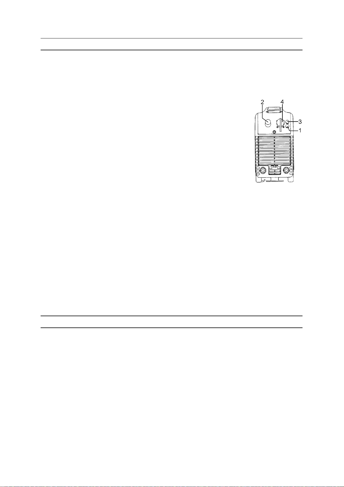
1. Ж¸лтая лампа п ерегрузки
2. Ручка плавной регулировки сварочного тока в пределах 4-250 A
3. Белая контрольная лампа
4. Разъ¸м пульта дистанционного управления
Внимание!
Необходимо использовать только рекомендуемые сечения сварочного и
возвратного кабеля (не менее 35 мм2)
(См. Список запасных частей).
bh11d001
4.2 Защита от перегрузок
Для защиты от перегрева выпрямители LHN 250 имеет встроенное
термореле, срабатывающее при превышении температуры выше допустимой
величины. При этом обесточиваются сварочные кабели и загорается
оранжевая контрольная лампа. При понижении температуры термореле
авт оматически включает выпрямитель.
5 Техническое обслуживание
5.1 Чистка
LHN 250 не требует специального обслуживания. Обычно достаточно
продувать установку чистым сжатым воздухом и очищать воздушный фильтр.
Если установка эксплуатируется в очень загрязненных условиях фильтр надо
очищать как можно чаще.
bh21d02r -- 7 --

6 ДИАГНОСТИКА НЕИСПРАВНОСТЕЙ
6.1 Возможные неисправности и меры по их устранению
Вид неисправности Меры по их ус тране нию
Не возбуждается дуга от сварочного
источника питания
В процессе св арки произошло отключение
источника питания.
Термореле срабатывает очень часто. S Проверьтенезабитливоздушный
Низкое качество сварки. S Проверьте правильность подключения
S Убедитесь, что сетевой выключатель
включен.
S Проверьте правильность соединения
сварочных кабелей.
S Убедитесь, что величина сварочного
тока установлена правильно.
S Проверьтенеработалолитермореле
(загорелась оранжевая лампа на
передней панели).
S Проверьте предохранитель.
фильтр.
S Убедитесь, что сварка не велась на
завышенных режимах. (перегрузка
источника питания).
сварочных кабелей.
S Убедитесь, что величина сварочного
тока установлена правильно.
S Проверьте состояние штучных
электродов.
7 ЗАКАЗ ЗАПАСНЫХ ЧАСТЕЙ
При заказе запасных частей, пожалуйста, укажите тип установки, серийный
номер, название и артикульный номер запасной детали. Это поможет
упростить заказ и ускорить отгрузку.
8 Дополнительные принадлежности
Пульт дистанционного управления PHA1 25 ì 0367 657 880
Пульт дистанционного управления PHA1 10 ì 0367 657 881
Пульт дистанционного управления PHA2 Hotstart 0367 601 880
Пульт дистанционного управления PHB1 0367 317 880
Пульт дистанционного управления PHB2 036 7 318 880
Пульт дистанционного управления PHC2 0367 620 880
Пульт дистанционного управления PHA5 0367 970 880
КабельдляпультаДУ 5 ì 0367 1 44 881
КабельдляпультаДУ 10 ì 0367 1 44 882
КабельдляпультаДУ 1,5 ì 0367 144 883
bh21d02r -- 8 --

ENGLISH
1SAFETY 10...........................................................
2 INTRODUCTION 10...................................................
2.1 Technical data 11............................................................
2.2 Equipment 12................................................................
2.3 Field of application 12.........................................................
3 INSTALLATION 12....................................................
3.1 Placing 12...................................................................
3.2 Connection 12...............................................................
4 OPERATION 13.......................................................
4.1 Start--up 13..................................................................
4.2 Overload protection 13........................................................
5 MAINTENANCE 13....................................................
5.1 Cleaning 13.................................................................
6 FAULT TRACING 14...................................................
6.1 Possible faults and measures to take 14.........................................
7 ORDERING OF SPARE PARTS 14......................................
8 EXTRA ACCESSORIES 14.............................................
DIAGRAM 15............................................................
SPARE PARTS LIST 16...................................................
TOCe
-- 9 --

1SAFETY
WARNING
ARC WELDING AND CUTTING CAN BE INJURIOUS TO YOURSELF AND OTHERS. TAKE PRECAUTIONS WHEN WELDING. ASK FOR YOUR EMPLOYER’S SAFETY PRACTICES WHICH SHOULD BE
BASED ON MANUFACTURERS’ HAZARD DATA.
ELECTRIC SHOCK -- Can kill
S Install and earth the welding unit in accordance with applicable standards.
S Do not touch live electrical parts or electrodes with bare skin, wet gloves or wet clothing.
S Insulate yourself from earth and the workpiece.
S Ensure your working stance is safe.
FUMES AND GASES -- Can be dangerous to health
S Keep your head out of the fumes.
S Use ventilation, extraction at the arc, or both, to keep fumes and gases from your breathing zone and
the general area.
ARC RAYS -- Can injure eyes and burn skin.
S Protect your eyes and body. Use the correct welding screen and filter lens and wear protective
clothing.
S Protect bystanders with suitable screens or curtains.
FIRE HAZARD
S Sparks (spatter) can cause fire. Make sure therefore that there are no inflammable materials nearby.
NOISE -- Excessive noise can damage hearing
S Protect your ears. Use ear defenders or other hearing protection.
S Warn bystanders of the risk.
MALFUNCTION -- Call for expert assistance in the event of malfunction.
READ AND UNDERSTAND THE INSTRUCTION MANUAL BEFORE INSTALLING OR OPERATING.
PROTECT YOURSELF AND OTHERS!
2 INTRODUCTION
Note!
This product is solely intended for arc welding.
The LHN 250 are one transistor controlled welding power source designed for
welding with coated electrodes and for TIG welding (touch start).
The advanced electronics provide rapid control response, low power demand and
excellent welding characteristics. Inverter technology contributes to low weight and
compact dimensions of the units.
The rounded slimline shape of the unit makes it comfortable to carry. The strap can
be folded to serve as a carrying handle, or fully extended to serve as a shoulder
strap.
bh21d02e
-- 1 0 --

2.1 Technical data
Performance:
at 35% duty cycle
at 60% duty cycle
at 100% duty cycle
Setting range continuously variable 4--250 A
Open circuit voltage 50--80 V
Mains supply:
voltage
frequency
fuse
mains cable, area
Enclosure class IP 23
Application class
Dimensions L x W x H 472x142x256
Weight 11 kg
250 A/30 V
180 A/27 V
140 A/26 V
400 V AC
50/60 Hz
16 A*
3x1,5 mm2**
*When welding below 100 A a 10 A slow fuse is adequate..
**Power cable ratings complies with Swedish regulations..
Duty cycle
The duty cycle refers to the time in per cent of a ten--minute period that you can weld
at a certain load without overloading the welding power source.
Enclosure class
The IP code indicates the enclosure class, i. e. the degree of protection against
penetration by solid objects or water. Equipment marked IP 23 is designed for indoor
and outdoor use.
Application class
The symbol indicates that the power source is designed for use in areas where
there is an increased electrical hazard.
-- 1 1 --bh21d02e

2.2 Equipment
LHN 250 is equipped with a remote control socket which activates automatically
when a remote control device is connected. NOTE! T he contact pins L and M must
be strapped in the remote device’s connection cable for automatic activation to
function.Theinverterissuppliedwitha3meterlongmainscable.
LHN 250 is delivered with 5 m eter long welding and return cables. These are
attached to cable connectors allowing quick change of polarity.
The manufacturer’s serial number is stamped on the rating plate.
2.3 Field of application
LHN 250 supply direct current, which allows you to weld most alloyed and
non--alloyed steels, stainless steels and cast iron.
With the LHN 250 you can use coated electrodes from 1.6 to 5 mm.
Tig--welding
TIG welding is particularly useful when high quality standards are required and when
welding thin sheet.
Before using the LHN 250 for TIG welding it must be equipped with a TIG torch and
gas valve, a cylinder of argon, an argon regulator, tungsten electrodes and, if
necessary, suitable filler metal.
The best method to use is the touch start, where you gently stroke the tungsten
electrode against the workpiece to establish the arc.
3 INSTALLATION
WARNING
This product is intended for repair and maintenance welding
In domestic or office environment this product m ay cause radio interference.
It is the responsibility of the user to take adequate precautions.
3.1 Placing
Place the machine so that there is nothing to prevent the cooling air from passing
through it.
3.2 Connection
To get maximum performance from the LHN 250 it must be fitted with a 16A slow
fuse.
The LHN 250 have mains voltage compensation, which means that ¦10%
fluctuation in the supply voltage produces only ¦0.2% variation in the welding
voltage.
LHN 250 is intended for 400V, 3 phase supplies. It can be used with 50 Hz or
60 Hz supplies.
bh21d02e
-- 1 2 --

4OPERATION
4.1 Start--up
The power switch is at the rear of the LHN 250. T h e white lamp on the front will glow
when the power is on.
1. Yellow lamp
2. Welding current control 4--250 A
3. White lamp
4. Remote control socket
The current is adjusted using the knob on the front.
Important!
Only use the accompanying welding cable and return cable, with a
cross--sectional area of 35 mm@.
(See list of spare parts for order number).
bh11d001
4.2 Overload protection
To save you worrying about overloading the LHN 250 it has a thermal cut-- out that
will trip before the temperature becomes too high. You ca n tell when the rectifier has
been overloaded because the yellow light comes on and it will no longer be possible
to weld.
5 MAINTENANCE
5.1 Cleaning
Normally it is sufficient to blow the welding power source clean regularly using dry
compressed air (reduced pressure), and to clean the filter in the front regularly.
In dusty and dirty environment the welding power source should be cleaned at
shorter intervals.
-- 1 3 --bh21d02e

6 FAULT TRACING
6.1 Possible faults and measures to take
Type of fault Measure
No arc is generated by the welding power
source.
The welding current is interrupted in the course
of welding.
The thermal cut--out trips frequently. S Check that the filter is not packed with dust.
Poor welding result. S Check that the welding and return cables
S Make sure the mains switch is on.
S Check that the welding and return cables
are properly connected.
S Make sure the welding current set is correct.
S Check if the thermal cut--out has tripped (the
orange indicating lamp on the front panel is
on).
S Check the mains fuse.
S Check that the ratings of the welding power
source have not been exceeded (overload
of the power source).
are properly connected.
S Make sure the welding current set is correct.
S Check that there is nothing wrong with the
electrodes.
7 ORDERING OF SPARE PARTS
When ordering a spare part, please state the type and serial number of the machine
as well as number of the spare part, according to the spare parts list.
This will simplify dispatch and ensure you get the right part.
8 EXTRA ACCESSORIES
Remote control device PHA1 25 m 0367 657 880
Remote control device PHA1 10 m 0367 657 881
Remote control device PHA2 Hotstart 0367 601 880
Remote control device PHB1 0367 317 880
Remote control device PHB2 0367 318 880
Remote control device PHC2 0367 620 880
Remote control device PHA5 0367 970 880
Connecting cable 5 m 0367 144 881
Connecting cable 10 m 0367 144 882
Connecting cable 1.5 m 0367 144 883
bh21d02e
-- 1 4 --

Diagram Схема
-- 1 5 --bh21e02a

Spare parts list Список запасных частей
Edition
98.02.01
cmha2p00
Ordering numbers LHN 250
0457 516 880 LHN 250 , Caddy 250
c=component designation in the circuit diagram
Item Qty Ordering no. Denomation Notes C
101 1 0366 296 003 Knob
102 1 0366 295 002 Switch 3--way QF1
103 1 0193 307 104 Cable clamp
104 1 0456 193 881 Mains cable
105
106 1 0468 208 001 Strap
107 1 0468 497 001 Clamp
108 1 0321 475 881 Knob
109 1 0366 285 001 Cover
110 2 0467 796 001 Grating
111 1 0468 462 001 Filter
112 1 0468 214 001 Cover
113 1 0369 857 886 Welding cable Complete
114 1 0369 857 887 Return cable Complete
-- 1 6 --bh21s02a

103
104
106
107
108
101
102
109
113
114
112
111
110
-- 1 7 --bh21s02a

c=component designation in the circuit diagram
Item Qty Ordering no. Denomation Notes C
201 1 0468 461 001 Gable
202 1 Busbar Included in sets item 500
203 4 0366 588 001 Nut
204 1 0457 392 001 Front
205 2 0366 306 881 Connector OKC XS12
206 1 0457 558 001 Current bar
207 1 0457 559 001 Current bar
208 5
0193 260 001
5
0193 260 180
Connector XS02,04
,07
209 1 0193 260 062 Connector XS09
210 1 0191 870 616 Potentiometer 10 kW 2W RP01
211 1
0193 759 001
1
0193 759 002
Indicator lamp 28V, white
Yellow
HL01
V05
212 1 0368 544 003 Burndy socket 12--way XS11
220 1 0468 029 001 Control transformer TC01
225 2 0192 903 506 Capacitor 1000 mF C02,03
227 1 Busbar Included in sets item 500
228 1 Busbar Included in sets item 500
229 1 0193 260 154 Connector 6--way 0.75mm@ XS01
1 0193 260 184 Cap 6--way
230 1 0193 260 150 Connector 2--way 0.75mm@ XS02
1 0193 260 180 Cap 2--way
231 1 0193 260 153 Connector 5--way 0.75mm@ XS10
1 0193 260 183 Cap 5--way
232 1 0193 260 006 Connector 7--way 0.35mm@ XS03
1 0193 260 185 Cap 7--way
234 1 Busbar Included in sets item 500
235 1 Busbar Included in sets item 500
236 1 0467 802 001 Guide
237 1 0481 870 884 Circuit board AP01
240 1 0455 661 029 Rivet
241 1 0486 328 880 Circuit board AP05
7 0194 034 001 Ferrite ring core L08,L09,
L10
-- 1 8 --bh21s02a

240
241
201
220
220
229
237
225
208
230
235
234
227
232
231
228
236
202
203
204
209
210
211
206
207
205
212
-- 1 9 --bh21s02a

c=component designation in the circuit diagram
Item
Qty
Ordering no. Denomation Notes c
301 1 0467 801 001 Fan 24 VDC EV01
302 1 Circuit board Included in sets item 504 AP02
303
304
120192 883 150
0193 316 208
Capacitor
Rectifier bridge
0.1 ⊃F 1000 VDC C01
V01,02
305 1 0467 800 001 Insulation
308 2 0467 797 001 Guide
309 2 0467 793 180 Heat sink
310 1 Circuit board Included in sets item 504 AP03
311 21 Spring Included in sets item 504
312 1 0468 016 881 Inductor Secondary L01
313
314
315
316
317
318
319
320
1
0192 716 004
2
0193 529 017
1
0468 496 001
1
0468 215 880 Inductor
1
1
2
2
Diode
Capacitor
Holder
Winding
Bobbin
Core
Clip
4.7 ⊃F
Complete
Included in item 316
Included in item 316
Included in item 316
Included in item 316
V06
C05
L02
321 1 0457 304 880 Shunt 120 mV at 140 A RS01
322
323
110320 805 886
0394 516 035
Capacitor
Spacer
0.1⊃F 400 VDC C04
324 1 Busbar Included in sets item 505
325 1 0320 655 009 Thermal cutout Opens at 130˚C,
ST01
Included in item 312
326 1 0457 308 880 Transformer coil TC02
327
328
140467 799 001
0193 312 101
Clip
Ferrite core
329 1 0193 669 002 Connector 2--way XS08
329a 0193 590 302 Sleeve 2 per connector
330 1 0455 646 883 Rectifier unit Complete
331 1 0457 557 880 Resistor Complete 8,2 k″ 5W R02
332 3 0193 948 001 Diode module V03,04
333 1 0455 650 005 Busbar Included in sets item 505
334 1 0455 650 004 Busbar Included in sets item 505
335 2 0467 648 884 Capacitor Complete C06
336 1 0455 650 006 Busbar Included in sets item 505
337 2 0191 745 011 Spacer sleeve
338 2 0455 569 002 Ferrite ring core L06,07
339 1 0455 569 003 Ferrite ring core L05
340 1 0468 538 002 Current bar Included in sets item 505
341 2 0457 695 001 Washer
-- 2 0 --bh21s02a

329,329a
332
310
311
327
328
339
309
324
312
314
326
325
301
304
313
303
336
333
302
308
334
335
330
305
337
338
331
315
323
317
320
318
319
340
321
Spare parts sets
Item Ordering no. Denomation Notes
500 0468 881 880 Busbars, primary Contains items
202,227,228,234,235,
504 0468 881 887 Transistor boards Contains items 302,310,311
505 0468 881 889 Busbars,
secondary
Contains items
208,324,333,334,336,340
322
341
-- 2 1 --bh21s02a

ESAB subsidiaries and representative offices
Europe
AUSTRIA
ESAB Ges.m.b.H
Vienna--Liesing
Tel: +43 1 888 25 11
Fax: +43 1 888 25 11 85
BELGIUM
S.A. ESAB N.V.
Brussels
Tel: +32 2 745 11 00
Fax: +32 2 726 80 05
THE CZECH REPUBLIC
ESAB VAMBERK s.r.o.
Prague
Tel: +420 2 819 40 885
Fax: +420 2 819 40 120
DENMARK
Aktieselskabet ESAB
Copenhagen--Valby
Tel:+4536300111
Fax:+4536304003
FINLAND
ESAB Oy
Helsinki
Tel: +358 9 547 761
Fax: +358 9 547 77 71
FRANCE
ESAB France S.A.
Cergy Pontoise
Tel:+33130755500
Fax:+33130755524
GERMANY
ESAB GmbH
Solingen
Tel: +49 212 298 0
Fax: +49 212 298 204
GREAT BRITAIN
ESAB Group (UK) Ltd
Waltham Cross
Tel: +44 1992 76 85 15
Fax: +44 1992 71 58 03
ESAB Automation Ltd
Andover
Tel: +44 1264 33 22 33
Fax: +44 1264 33 20 74
HUNGARY
ESAB Kft
Budapest
Tel:+3612044182
Fax:+3612044186
ITALY
ESAB Saldatura S.p.A.
Mesero (Mi)
Tel:+3902979681
Fax:+390297289181
THE NETHERLANDS
ESAB Nederland B.V.
Utrecht
Tel: +31 30 248 59 22
Fax: +31 30 248 52 60
NORWA Y
AS ESAB
Larvik
Tel:+4733121000
Fax:+4733115203
POLAND
ESAB Sp.z.o.o
Warszaw
Tel: +48 22 813 99 63
Fax: +48 22 813 98 81
PORTUGAL
ESAB Lda
Lisbon
Tel: +351 1 837 1527
Fax: +351 1 859 1277
SLOVAKIA
ESAB Slovakia s.r.o.
Bratislava
Tel:+421744882426
Fax:+421744888741
SPAIN
ESAB Ibérica S.A.
Alcobendas (Madrid)
Tel: +34 91 623 11 00
Fax: +34 91 661 51 83
SWEDEN
ESAB Sverige AB
Gothenburg
Tel:+4631509500
Fax:+4631509222
ESAB International AB
Gothenburg
Tel:+4631509000
Fax:+4631509360
SWITZERLAND
ESAB AG
Dietikon
Tel: +41 1 741 25 25
Fax: +41 1 740 30 55
North and South America
ARGENTINA
CONARCO
Buenos Aires
Tel: +54 11 4 753 4039
Fax: +54 11 4 753 6313
BRAZIL
ESAB S.A.
Contagem--MG
Tel: +55 31 333 43 33
Fax: +55 31 361 31 51
CANADA
ESAB Group Canada Inc.
Missisauga, Ontario
Tel: +1 905 670 02 20
Fax: +1 905 670 48 79
MEXICO
ESAB Mexico S.A.
Monterrey
Tel: +52 8 350 5959
Fax: +52 8 350 7554
USA
ESAB Welding & Cutting Products
Florence, SC
Tel: +1 843 669 44 11
Fax: +1 843 664 44 58
Asia/Pacific
AUSTRALIA
ESAB Australia Pty Ltd
Ermington
Tel: +61 2 9647 1232
Fax: +61 2 9748 1685
CHINA
Shanghai ESAB A/P
Shanghai
Tel: +86 21 6539 7124
Fax: +86 21 6543 6622
INDIA
ESAB India Ltd
Calcutta
Tel: +91 33 478 45 17
Fax: +91 33 468 18 80
INDONESIA
P.T. Esabindo Pratama
Jakarta
Tel: +62 21 460 01 88
Fax: +62 21 461 29 29
MALAYSIA
ESAB (Malaysia) Snd Bhd
Selangor
Tel: +60 3 703 36 15
Fax: +60 3 703 35 52
SINGAPORE
ESAB Singapore Pte Ltd
Singapore
Tel: +65 861 43 22
Fax: +65 861 31 95
ESAB Asia/Pacific Pte Ltd
Singapore
Tel: +65 861 74 42
Fax: +65 863 08 39
SOUTH KOREA
ESAB SeAH Corporation
Kyung--Nam
Tel:+825512898111
Fax: +82 551 289 88 63
THAILAND
ESAB (Thailand) Ltd
Samutprakarn
Tel: +66 2 393 60 62
Fax: +66 2 748 71 11
UNITED ARAB EMIRATES
ESAB Middle East
Dubai
Tel: +971 4 338 88 29
Fax: +971 4 338 87 29
Representative offices
BULGARIA
ESAB Representative Office
Sofia
Tel/Fax: +359 2 974 42 88
EGYPT
ESAB Egypt
Dokki--Cairo
Tel: +20 2 390 96 69
Fax: +20 2 393 32 13
ROMANIA
ESAB Representative Office
Bucharest
Tel/Fax: +40 1 322 36 74
RUSSIA--CIS
ESAB Representative Office
Moscow
Tel: +7 095 937 98 20
Fax: +7 095 937 95 80
ESAB Representative Office
St Petersburg
Tel: +7 812 325 43 62
Fax: +7 812 325 66 85
Distributors
For addresses and phone
numbers to our distrubutors in
other countries, please visit our
home page
www.esab.com
ESAB Welding Equipment AB
SE--695 81 LAXÅ
SWEDEN
Phone +46 584 81 000
Fax +46 584 123 08
www.esab.com
000930
 Loading...