

INSTRUCTIONS for
F-15-127
October, 2006
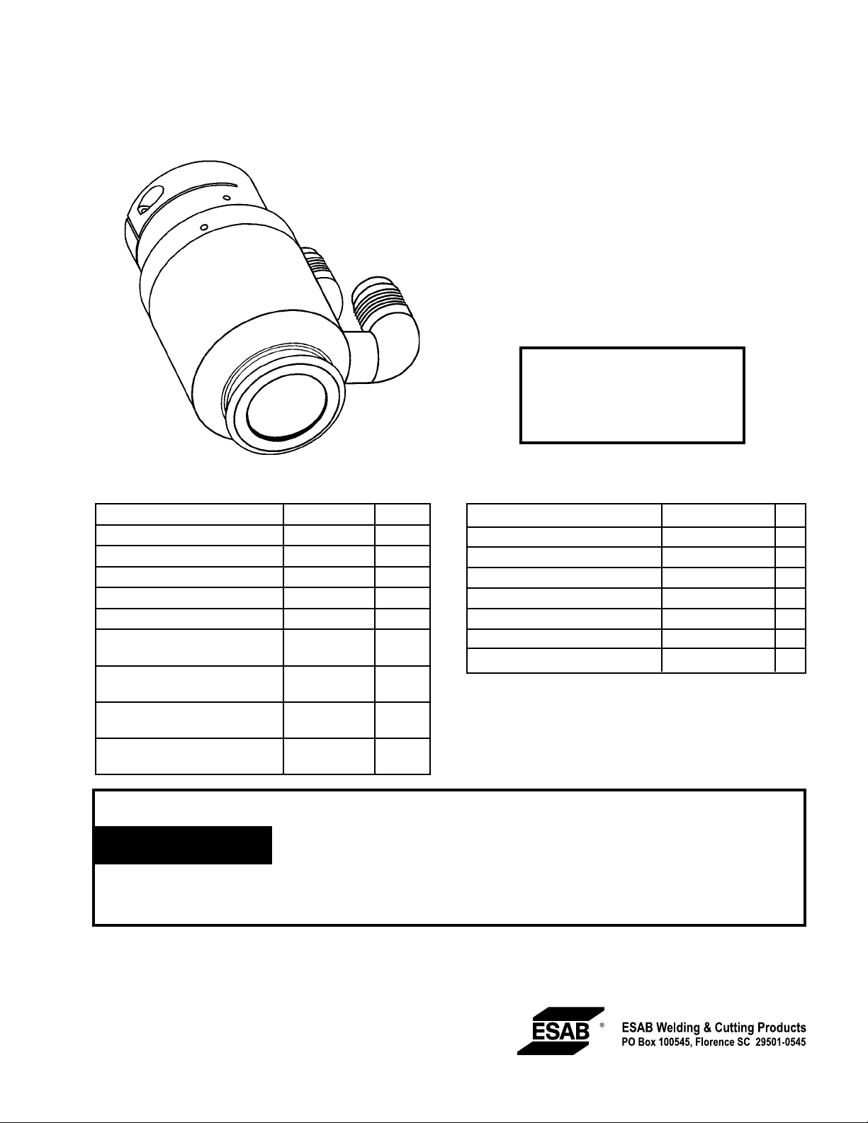
Bubble Muffler System
for PT-15XL
P/N 2232615
The Bubble Muffler System creates a bubble of air surrounded by water so that a PT-15XL Plasma Arc Torch can
be used underwater with oxygen/water-injection cutting
without significant sacrifice of cut quality. This system also
permits operation above water as the flow of water through
the muffler reduces fume, noise, and arc U.V. radiation.
Compressed Air Supply
(Air Curtain)
Source: 80 psi @ 1200cfh
(5.5 bar @ 34 m3h)
Clean, dry & oil-free shop air
Optional Accessories
Control Box Assembly P/N 33383 1
Control Cable, 18 GA, 3-Cond P/N 33253 25 ft.
Control Cable, 18 GA, 3-Cond P/N 33254 50 ft.
Control Cable, 18 GA, 3-Cond P/N 33255 75 ft.
Control Cable, 18 GA, 3-Cond P/N 33256 100 ft.
Control Cable, 18 GA, 3-Cond P/N 33257 125 ft.
Hose, 3/4" ID for Water P/N 2027202 Specify
Length
Hose, 3/4" ID for Water P/N 23079995 Specify
Length
Fittings, 3/8" Hose to Bubble
Muffler
Fittings, Nipple 10N40 Nut
for 3/8" Hose to Control Box
P/N 2233298 AR
P/N 347995 AR
THE BUBBLE MUFFLER CAN NOT BE USED WHEN USING H35 OR CH
GAS MIXES. THE WATER LEVEL MUST BE LOWERED 4 TO 6 INCHES BE
WARNING
NEATH THE BOTTOM OF THE PLATE.
FAILURE TO COMPLY TO THIS WARNING CAN RESULT IN A HYDROGEN
DETONATION.
Bubble Muffler System
Muffler, Insulated, Underwater P/N 21131 1
Cup, Nozzle Retaining, Beveling P/N 20758 1
Strainer P/N 2133340 1
Water Pump P/N 2135445 1
Adaptor, 1.06-12F 3/4" Hose P/N 2135571 3
Adaptor, 3/4" NPTM, 3/4" Hose P/N 2135572 1
PIP, Pipe S.ST 2.357X2.00 CL P/N 43350490 1
Bushing Pipe 2X3/4 P/N 44056390 1
NOTE: P/N 2232615 may be ordered as part of P/N 2233409
Bubble Muffler Addition which includes hoses, adaptors, solenoid valves, fittings and a regulator.
4

BE SURE THIS INFORMATION REACHES THE OPERATOR.
YOU CAN GET EXTRA COPIES THROUGH YOUR SUPPLIER.
CAUTION
These INSTRUCTIONS are for experienced operators. If you are not fully familiar with the
principles of operation and safe practices for arc welding and cutting equipment, we urge
you to read our booklet, “Precautions and Safe Practices for Arc Welding, Cutting, and
Gouging,” Form 52-529. Do NOT permit untrained persons to install, operate, or maintain
this equipment. Do NOT attempt to install or operate this equipment until you have read
and fully understand these instructions. If you do not fully understand these instructions,
contact your supplier for further information. Be sure to read the Safety Precautions before installing or operating this equipment.
USER RESPONSIBILITY
This equipment will perform in conformity with the description thereof contained in this manual and accompanying labels and/or inserts when installed, operated, maintained and repaired in accordance with the instructions provided. This equipment must be checked periodically. Malfunctioning or poorly maintained equipment
should not be used. Parts that are broken, missing, worn, distorted or contaminated should be replaced immediately. Should such repair or replacement become necessary, the manufacturer recommends that a telephone
or written request for service advice be made to the Authorized Distributor from whom it was purchased.
This equipment or any of its parts should not be altered without the prior written approval of the manufacturer.
The user of this equipment shall have the sole responsibility for any malfunction which results from improper
use, faulty maintenance, damage, improper repair or alteration by anyone other than the manufacturer or a service facility designated by the manufacturer.
2

TABLE OF CONTENTS
Section / Title Page
1.0 Safety Precautions . . . . . . . . . . . . . . . . . . . . . . . . . . . . . . . . . . . . . . . . . . . . . . . . . . . . . . . . . . . . . . . . . . . . . . . . . . . . . . . . . . . .5
2.0 Installation. . . . . . . . . . . . . . . . . . . . . . . . . . . . . . . . . . . . . . . . . . . . . . . . . . . . . . . . . . . . . . . . . . . . . . . . . . . . . . . . . . . . . . . . . . . .7
3.0 Operation . . . . . . . . . . . . . . . . . . . . . . . . . . . . . . . . . . . . . . . . . . . . . . . . . . . . . . . . . . . . . . . . . . . . . . . . . . . . . . . . . . . . . . . . . . .11
4.0 Replacement Parts . . . . . . . . . . . . . . . . . . . . . . . . . . . . . . . . . . . . . . . . . . . . . . . . . . . . . . . . . . . . . . . . . . . . . . . . . . . . . . . . . . .13
3

TABLE OF CONTENTS
4

SECTION 1 SAFETY PRECAUTIONS
1.0 Safety Precautions
Users of ESAB welding and plasma cutting equipment have the ultimate responsibility for ensuring
that anyone who works on or near the equipment observes all the relevant safety precautions. Safety
precautions must meet the requirements that apply to this type of welding or plasma cutting equipment.
The following recommendations should be observed in addition to the standard regulations that apply
to the workplace.
All work must be carried out by trained personnel well acquainted with the operation of the welding
or plasma cutting equipment. Incorrect operation of the equipment may lead to hazardous situations
which can result in injury to the operator and damage to the equipment.
1. Anyone who uses welding or plasma cutting equipment must be familiar with:
- its operation
- location of emergency stops
- its function
- relevant safety precautions
- welding and / or plasma cutting
2. The operator must ensure that:
- no unauthorized person stationed within the working area of the equipment when it is started up.
- no one is unprotected when the arc is struck.
3. The workplace must:
- be suitable for the purpose
- be free from drafts
4. Personal safety equipment:
- Always wear recommended personal safety equipment, such as safety glasses, flame proof
clothing, safety gloves.
- Do not wear loose fitting items, such as scarves, bracelets, rings, etc., which could become
trapped or cause burns.
5. General precautions:
- Make sure the return cable is connected securely.
- Work on high voltage equipment may only be carried out by a qualified electrician.
- Appropriate fire extinquishing equipment must be clearly marked and close at hand.
- Lubrication and maintenance must not be carried out on the equipment during operation.
5

SECTION 1 SAFETY PRECAUTIONS
WELDING AND PLASMA CUTTING CAN BE INJURIOUS TO YOURSELF
AND OTHERS. TAKE PRECAUTIONS WHEN WELDING OR CUTTING. ASK
WARNING
ELECTRIC SHOCK - Can kill.
- Install and earth (ground) the welding or plasma cutting unit in accordance with applicable standards.
- Do not touch live electrical parts or electrodes with bare skin, wet gloves or wet clothing.
- Insulate yourself from earth and the workpiece.
- Ensure your working stance is safe.
FUMES AND GASES - Can be dangerous to health.
- Keep your head out of the fumes.
- Use ventilation, extraction at the arc, or both, to take fumes and gases away from your breathing zone
and the general area.
FOR YOUR EMPLOYER’S SAFETY PRACTICES WHICH SHOULD BE BASED
ON MANUFACTURERS’ HAZARD DATA.
ARC RAYS - Can injure eyes and burn skin.
- Protect your eyes and body. Use the correct welding / plasma cutting screen and filter lens and wear
protective clothing.
- Protect bystanders with suitable screens or curtains.
FIRE HAZARD
- Sparks (spatter) can cause fire. Make sure therefore that there are no inflammable materials nearby.
NOISE - Excessive noise can damage hearing.
- Protect your ears. Use earmuffs or other hearing protection.
- Warn bystanders of the risk.
MALFUNCTION - Call for expert assistance in the event of malfunction.
READ AND UNDERSTAND THE INSTRUCTION MANUAL BEFORE INSTALLING OR OPERATING.
PROTECT YOURSELF AND OTHERS!
6
SECTION 2 INSTALLATION
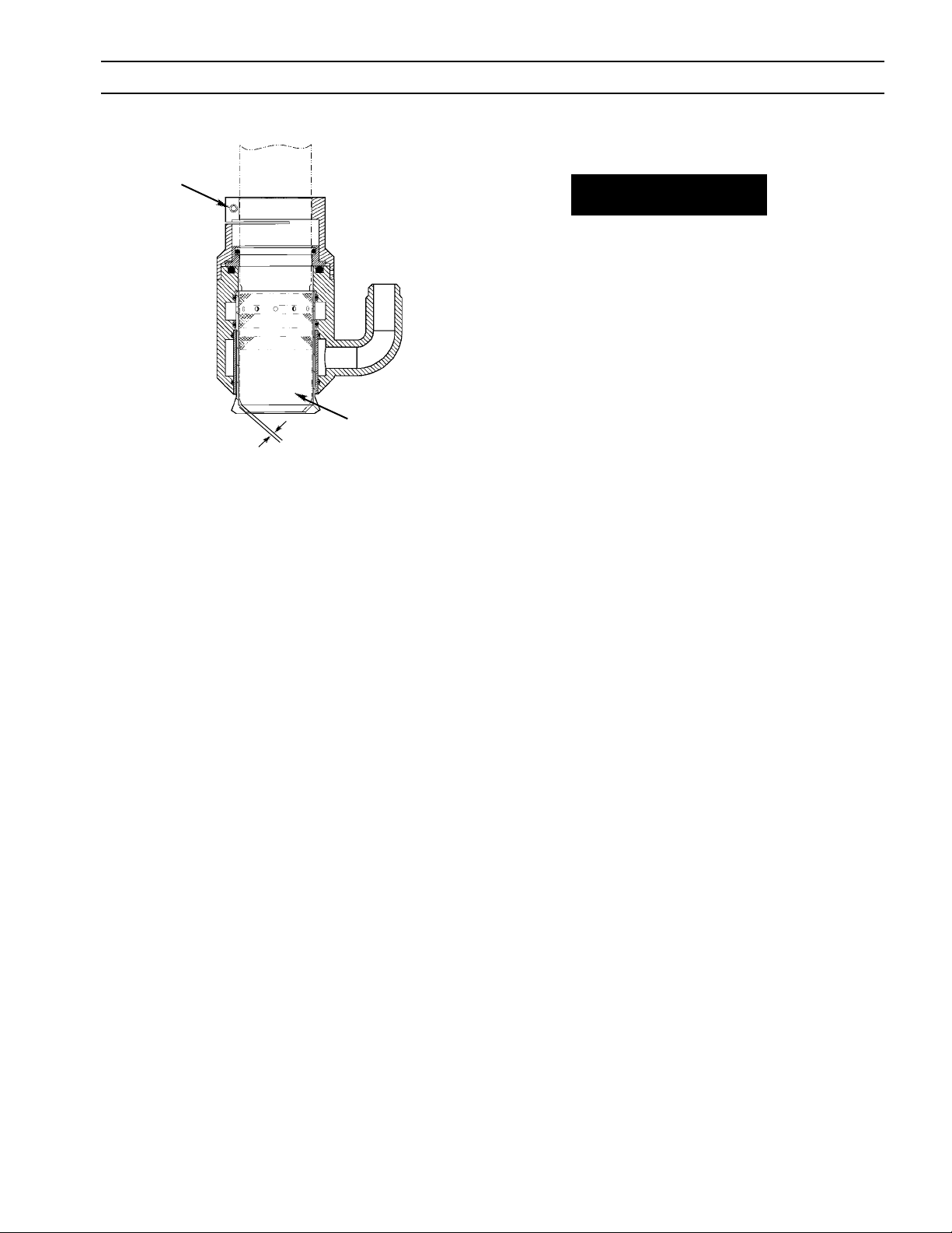
A. Installation and Adjustment of the Bubble Muffler
ALLEN
SCREW
(see Figure 1)
WARNING
Electric shock can kill. Disconnect power to power source before
touching or servicing the Air Curtain at the torch. Disconnect
power to the control box before servicing.
NOTE: Lubrication of all O-rings with silicone grease is recommend-
ed.
1. Remove the brass nozzle Retaining Cup from the torch.
2. Slide the chrome plated Bubble Muffler clamp onto the torch
TORCH
RETAINING
.040-.060
Figure 1. Bubble Muffler Installation
CUP
and about 1/2 inch up the torch sleeve (handle).
3. Replace the Nozzle Retaining Cup and any front-end parts you
may have removed from the torch.
4. Install the Bubble Muffler Sleeve in the Bubble Muffler Main
Body. Make sure it bottoms completely.
5. Install the Bubble Muffler Body (including the Bubble Muffler
Sleeve) over the completely assembled Torch and snap it onto
the Bubble Muffler Clamp.
6. Adjust the position of the Bubble Muffler on the torch until a
gap of between .040 and .060 inch is obtained between the
bubble muffler sleeve and the nozzle retaining cup. Lock the
Bubble Muffler in position by tightening with an Allen screw on
the Bubble Muffler Clamp.
NOTE: The Bubble Muffler Sleeve must remain completely bottomed
in the Bubble Muffler Main Body for the adjustment in step 6
to be correct.
After tightening the Allen screw in the Bubble Muffler Clamp,
the gap between the sleeve and torch cup should be nearly
uniform all the way around.
7
SECTION 2 INSTALLATION
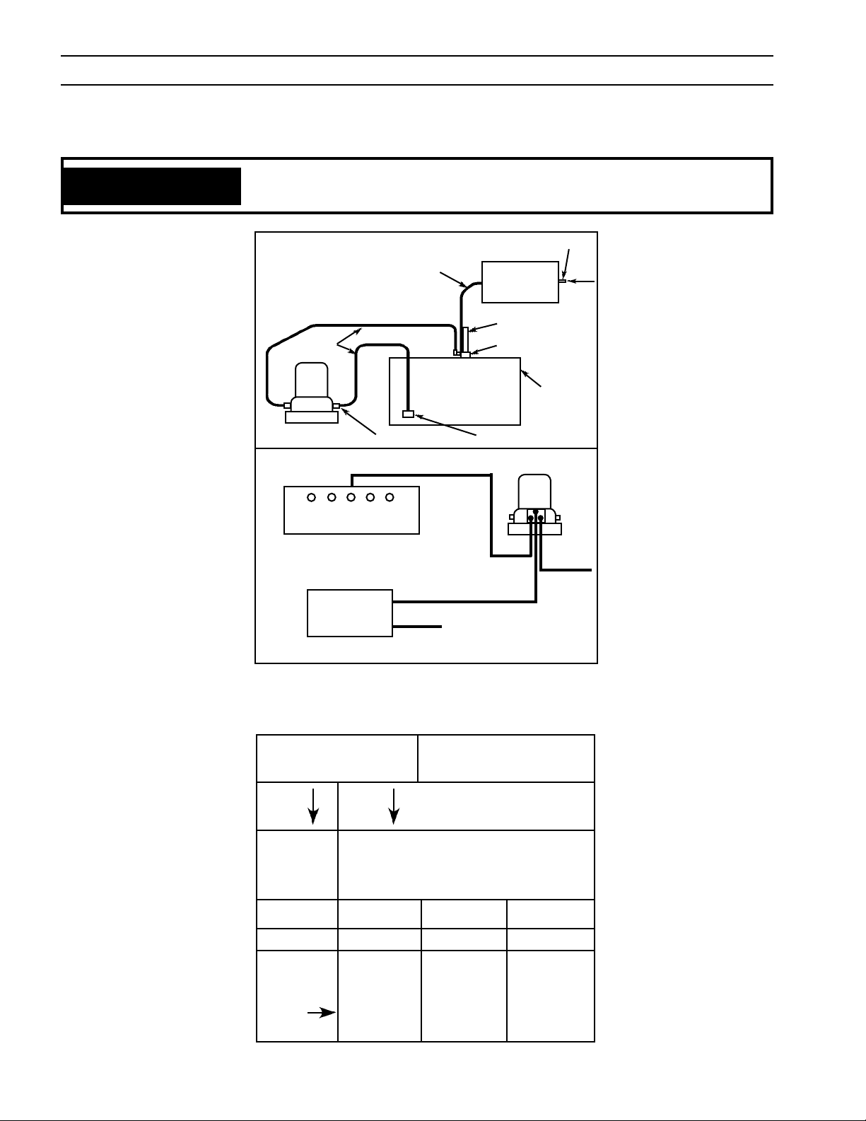
B. Installation of the Water Pump (P/N 2135445)
IF A BUBBLE MUFFLER IS BEING USED, TURN OFF WATER RECIRCU
WARNING
LATING PUMP.
3/8" ID HOSE
3/8" ID HOSE
3/4" ID
HOSE
PUMP
INLET
CONTROL CABLE
APPROPRIATE AMPHENOL
CONNECTOR ON BACK
FLOW CONTROL
(or Cutting Machine Control)
AIR CURTAIN
CONTROL BOX
Figure 2. Installation of H2O Pump
WATER
STRAINER
CONTROL CABLE
115 VAC
OPTIONAL
AIR CURTAIN
CONTROL
BOX
TORCH
BUBBLE MUFFLER
WATER
TABLE
PUMP
POWER
AIR
Water/Bubble Muffler Pump Input Voltage
50 Hz Operation of ESAB
60 Hz Motors
To On
Use
60 50 Hertz
Hertz Operational Voltage
Motor Ratings +5%
230 V 190 V 200 V 208 V
460 V 380 V 400 V 415 V
Multiply
Nameplate .70 .75 .80
HP By
8

SECTION 2 INSTALLATION
C. Installation of the Control Box Assembly (P/N 33383)
1. Mount the control box at a convenient location and use the 3/8" ID hose muffler to connect the box with the Bubble
Muffler mounted on the torch.
2. Connect the control box to a source of oil free shop air capable of delivering at least 20 scfm at 80 psig. The hose used
should be at least 3/8" ID.
3. Use the SJO wire supplied to connect the control to the cutting machine control. If the ESP system is used, then the
connection may be made to appropriate amphenol connector on the back of the flow control. The connection of the
control is made at the terminals marked F. C. An appropriate cable may be selected from the table of optional accessories.
4. The user supplied 115 V ac may be connected to the terminals so marked. This will allow manual operation of the air
curtain control.
5. Connect a ground wire to the stud provided in the control box.
8
9
7
4
Figure 3. Bubble Muffler Assembly, P/N 21131
3
1
2
6
5
ITEM QTY. PART
NO. REQ. NO. DESCRIPTION
1 2 21431 O-RING, 2.364 ID X .070 NEOP 70A
2 2 21430 O-RING, 2.175 ID X .103 NEOP 70 A
3 1 21432 O-RING, 2.100 ID X .210 NEOP 70A
4 1 85W87 O-RING, 1.98 ID X .139 NEOP 70A
5 1 21128 SLEEVE
6 1 21130 MAIN BODY
7 1 21127 INSULATOR, CLAMP
8 1 21129 CLAMP
9 1 61640912 SCREW, #10-32X3/4" STAIN. STEEL SOCKET HEAD CAP
NOTE: 4 each of the above o-rings are supplied.
9

SECTION 2 INSTALLATION
10

SECTION 3 OPERATION
D. Operation
1. Provide control box with oil free air at 80 psig minimum. Energize solenoid in control box and adjust regulator screw
on box to 30 psig delivery.
2. Place switch to AUTO. The system should turn on when the preflow begins. The pump will recirculate approximately 20
gpm from the water table.
WARNING
Electric shock can kill. Disconnect power to power source before touching or servicing the air curtain at the torch.
Disconnect power to the control box before servicing.
11

SECTION 3 OPERATION
12

SECTION 4 REPLACEMENT PARTS
8*, 9
4
5
* Air Regulator and pressure gauge are supplied together as item 8. Regulator w/gauge P/N 522368.
6
7
3
Figure 4, Air Curtain Control Box Assembly
10
11
1
2
ITEM QTY. PART
NO. REQ. NO. DESCRIPTION
1 2 180W38 CONNECTOR, STRAIN RELIEF
2 1 951041 TERMINAL, BLOCK, 4 POSITIONS
3 1 636702 SWITCH, DPDT 3 POSITIONS
4 2 858775 ADAPT. BULKHD. B SIZE, 1/4 NPT
5 2 182W82 ELBOW, STREET 90° BRASS
6 1 636387 SOLENOID VALVE
7 1 67101075 NIPPLE, CLOSE, 1/4 NPT BR. M TO M
8 1 522368 REGULATOR W/GAUGE
9 2 60101025 PLUG, 1/8" NPT ALLEN HEAD
10 1 67100081 NIPPLE, 2" LG. 1/4NPT BRASS M TO M
11 1 68161103 TEE, 1/4 NPT BRASS
13

SECTION 4 REPLACEMENT PARTS
14

NOTES
15

ESAB Welding & Cutting Products, Florence, SC Welding Equipment
COMMUNICATION GUIDE - CUSTOMER SERVICES
A. CUSTOMER SERVICE QUESTIONS:
Telephone: (800)362-7080 / Fax: (800) 634-7548 Hours: 8:00 AM to 7:00 PM EST
Order Entry Product Availability Pricing Order Information Returns
B. ENGINEERING SERVICE:
Telephone: (843) 664-4416 / Fax : (800) 446-5693 Hours: 7:30 AM to 5:00 PM EST
Warranty Returns Authorized Repair Stations Welding Equipment Troubleshooting
C. TECHNICAL SERVICE:
Telephone: (800) ESAB-123/ Fax: (843) 664-4452 Hours: 8:00 AM to 5:00 PM EST
Part Numbers Technical Applications Specifications Equipment Recommendations
D. LITERATURE REQUESTS:
Telephone: (843) 664-5562 / Fax: (843) 664-5548 Hours: 7:30 AM to 4:00 PM EST
E. WELDING EQUIPMENT REPAIRS:
Telephone: (843) 664-4487 / Fax: (843) 664-5557 Hours: 7:30 AM to 3:30 PM EST
Repair Estimates Repair Status
F. WELDING EQUIPMENT TRAINING
Telephone: (843)664-4428 / Fax: (843) 679-5864 Hours: 7:30 AM to 4:00 PM EST
Training School Information and Registrations
G. WELDING PROCESS ASSISTANCE:
Telephone: (800) ESAB-123 Hours: 7:30 AM to 4:00 PM EST
H. TECHNICAL ASST. CONSUMABLES:
Telephone : (800) 933-7070 Hours: 7:30 AM to 5:00 PM EST
IF YOU DO NOT KNOW WHOM TO CALL
Telephone: (800) ESAB-123
Fax: (843) 664-4462
Hours: 7:30 AM to 5:00 PM EST
or
visit us on the web at http://www.esabna.com
The ESAB web site offers
Comprehensive Product Information
Material Safety Data Sheets
Warranty Registration
Instruction Literature Download Library
Distributor Locator
Global Company Information
Press Releases
Customer Feedback & Support
F15-127 10/2006
 Loading...