

ESAB A6 TFD1, A6 TFD2, A6 TGD1 Simplified Service Manual

A6 TFD1/TFD2/
TGD1
Automatic welding machine
Simplified service manual
333 534--003
9612

LIST OF CONTENTS Sida
SAFETY 4.....................................................
TECHNICAL DESCRIPTION 5...................................
INSTALLATION 10...............................................
OPERATION 11.................................................
MAINTENANCE 13..............................................
TROUBLESHOOTING 14.........................................
DIMENSION DRAWING 15........................................
DIAGRAM 17....................................................
SPARE PARTS LIST A6 TFD1/TFD2/TGD1 19.......................
Rights reserved to alter specifications without notice.

WARNING
ARC WELDING AND CUTTING CAN BE INJURIOUS TO YOURSELF AND OTHERS.
TAKE PRECAUTIONS WHEN WELDING. ASK FOR YOUR EMPLOYER’S SAFETY
PRACTICES WHICH SHOULD BE BASED ON MANUFACTURERS’ HAZARD DATA.
ELECTRIC SHOCK -- Can kill
S Install and earth the welding unit in accordance with applicable standards.
S Do not touch live electrical parts or electrodes with bare skin, wet gloves or
wet clothing.
S Insulate yourself from earth and the workpiece.
S Ensure your working stance is safe.
FUMES AND GASES -- Can be dangerous to health
S Keep your head out of the fumes.
S Use ventilation, extraction at the arc, or both, to keep fumes and gases from
your breathing zone and the general area.
ARC RAYS -- Can injure eyes and burn skin.
S Protect your eyes and body. Use the correct welding screen and filter lens
and wear protective clothing.
S Protect bystanders with suitable screens or curtains.
FIRE HAZARD
S Sparks (spatter) can cause fire. Make sure therefore that there are no
inflammable materials nearby.
MALFUNCTION
S Call for expert assistance in the event of malfunction.
READ AND UNDERSTAND THE INSTRUCTION MANUAL BEFORE
INST ALLING OR OPERATING THE EQUIPMENT
PROTECT YOURSELF AND OTHERS!
mvarnen1
-- 3 --

SAFETY
Users of ESAB automatic welding machines have ultimate responsibility for ensuring
that anyone who works on or near the equipment observes all the relevant safety
precautions.
The following recommendations should be observed in addition to the standard
regulations that apply to the work place.
All work must be carried out according to the specified instructions by personnel who
are thoroughly familiar with the operation of the welding machine.
Incorrect or unintentional operation of the equipment may lead to a hazardous
situation which can result in injury to the operator and damage to the equipment.
1. Anyone who uses the automatic welding machine must be familiar with:
S its operation
S the location of emergency stops
S its function
S relevant safety precautions
To make this easier each switch, pushbutton or potentiometer is marked with a
symbol or text that indicates its function when activated.
2. The operator must ensure that:
S no unauthorized person is stationed within the working area of the machine
when it is started up.
S that no--one is in a hazardous position when the carriage or slide mechan-
isms are operated.
3. The work place must:
S be clear of mechanical components, tools, or other obstructions that could
prevent the operator from moving freely within the working area.
S be organized so that there is free access to the emergency stop.
4. Personal safety equipment
S Always wear recommended personal safety equipment, such as safety
glasses, flame--proof clothing, safety gloves.
S Do not wear loose--fitting items, such as scarves, bracelets, etc., which could
become trapped.
5. General precautions
Live electrical components are normally shielded from accidental contact.
S Make sure the return cable is connected securely.
S Work on high voltage components m ay only be carried out by a qualified
electrician.
S Appropriate fire extinguishing equipment must be clearly marked and close
at hand.
S Lubrication and maintenance must not be carried out on the equipment dur-
ing its operation.
df00f1ea
-- 4 --

TECHNICAL DESCRIPTION
The A6 TFD1 automatik welding machine is mounted on a tractor unit and intended for DC
or AC submerged--arc welding of butt and fillet welds.
The A6
TFD2 automatik welding machine with two welding heads is mounted on a tractor
unit and intended for DC or AC submerged--arc welding of butt and fillet welds.
The A6 TGD1 automatik welding machine
is mounted on a tractor unit and intended for DC
MIG/MAG--welding of butt and fillet welds.
Welding head position is adjustable by means of vertical and horisontal crossslides, with an
angular slide for angular adjustment.
A6 TFD1 A6 TFD2 A6 TGD1
Permissible load 1500 A DC/AC 1500 A DC/AC 600 A DC
Wire diameter
solid wire
hollow wire
3,0-- 6,0 mm 3,0-- 6,0 mm 1,0--2,4 mm
1,6-- 3,2 mm
Wire feed speed, max. 4,2 m/min 4,2 m/min 17,5 m/min
Travel speed, max. 2,5 m/min 2,5 m/min 2,5 m/min
Wire weight, max. 30 kg 30 kg 30 kg
Flux hopper volume 10 l 10 l
Weight (excl. wire and flux) 110 kg 158 kg 100 kg
Brake hub torque 1,5 Nm 1,5 Nm 1,5 Nm
Sideways tipping angle, max.
25_ 25_ 25_
Control voltage 42 V AC 42 V AC 42 V AC
cfa4d1ea
-- 5 --

TheA6Tautomaticweldingmachineconsistsof: (See the pictures on page 7)
1. Brake hub
2. Wire straightener
for feeding and straightening the filler wire before it enters the contact device and contact
jaws or contact tip, and to carry weld ing current from the shunt to the contact device.
The straightener clamp can be rotated around the wire drive unit gearbox, e,g. when
welding with leading or trailing wire and when fillet welding.
3. Handle
for adjusting the position of the tractor, manual transport or adjustment while welding is
in progress.
4. Slide, hand--operated for transverse adjustment of the welding head
5. Slide, hand--operated for vertical adjustment of the welding head
6. Insulator, for galvanic insulation of live parts, e.g. the welding head and the carriage
7. Tractor unit
with four wheels, of which two are g rooved for use on rails. The tractor is powered by a
geared motor with chain drive to the two axles, so that all four wheels are driven.
Motor supply voltage 42 V
Motor speed 3220 rpm
Motor torque 27 Ncm (0.27 Nm)
Gear ratio 187.5:1
Gearbox output torque 22.5 Nm
Final reduction ratio 64:15
Sprocket ratio 1:1
8. Wire feed motor, A6 VEC (see instructions 333 533--003)
Wire feed motor with reduction gear 42 V (A6 TFD1/A6 TFD2)
Motor speed 4000 rpm
Gear ratio 156,1
Wire feed motor with reduction gear 42 V (A6 TGD1)
Motor speed 8000 rpm
Gear ratio 74:1
9. Control lever, for disengaging the d rive for manual transport
10. PEG 1 control box
Additional parts:
11. Wire reel, for max. 30 kg of filler wire
12. Flux hopper
13. D35 contact equipment, intended for use with 3.0 -- 6.0 mm wire
Additional parts for the A6 TGD1:
14. Hoses, for gas and cooling water (14/6.3 mm)
15. Solenoid valve, 42 V
cfa4d1ea
-- 6 --

A6 TFD1
A6 TGD1
A6 TFD2
cfa4d1ea
-- 7 --

Extra accessories for the A6 TFD1 A6 TFD2 and A6 TGD1 Ordering no.
Fine wire straightener (not for the A6 TFD2)
332 565--880
when accurate wire straightening is required for single wire
not exceeding 2.5 mm diameter
Guide wheel bogey (not for the A6 TFD2) 6711 257--80
Rail set (2 m) 6715 039--80
Guide rail with magnets (3 m), (several lengths of guide rail can be used together) 154 203--880
Extra accessories for the A6 TFD1 (submerqed-arc welding)
Fine wire straightener
145 787--880
when accurate wire straightening is required for twin wire not
exceeding 2.5 mm diameter
D20 contact equipment for single wire:
without contact tip and feed roller
with contact tip and feed rollers for 1.6 -- 3.0 mm
wire with contact tip and feed rollers for 3.0 -- 5.0 mm wire
334 289--880
--881
--882
D35 contact equipment for single wire (L=Length of the contact device)
without contact jaws and feed rollers (L=220 mm)
with contact jaws and feed rollers for 3.0 -- 6.0 mm (L=220 mm)
without contact jaws and feed rollers (L=275 mm)
with contact jaws and feed rollers for 3.0 -- 6.0 mm (L=275 mm)
334 290--880
--881
--882
--883
D35 contact equipment for twin wire, with fine wire straightener and flux nozzle
without contact tip and feed rollers (L=220 mm)
without contact tip and feed rollers (L=275 mm)
without contact jaws and feed rollers (L=220 mm)
without contact jaws and feed rollers (L=275 mm)
with contact tip and feed rollers 1.2-- 2 .5 mm (L=220 mm)
with contact tip and feed rollers 1.2-- 2 .5 mm (L=275 mm)
with contact jaws and feed rollerc3 2.5-3,0 mm (L=220 mm)
with contact jaws and feed rollers 2.5-3,0 mm (L=275 mm)
with flux tube
334 291--880
--881
--882
--883
--884
--885
--886
--887
153 299--880
Contact tube curved, D20, for use in fillet welding 155 197--001
Flux funnel, for D20 contact equipment with insulating sleeve 145 221--881
Flux funnel
2549 008--80
for D35 contact equipment, including
Insert, height 18 mm
Insert, height 30 mm
2549 003--02
2549 003--01
OPC flux recovery unit, (see instruction manual 333 125--001) 148 140--880
Wire reel, steel 416 492--880
cfa4d1ea
-- 8 --

Guide lamp
for D35 contact equipment
for D20 contact equipment
153 143--880
--882
Strip cladding head, for welding 30--100 mm strip 155 972--880
Accessory set for air/arc gouging 153 592--880
Conversion set
334 299--880
consisting of a wire feed unit for an A6 SFD1 for conversion of an existing
A6 TFD1 automatic welding machine to MIG/MAG--welding
(wire diameter 1.0 -- 3.2 mm)
Extra accessories for the A6 TFD2 (submerged--arc welding)
OPC flux recovery unit, (see instruction manual 333 125 --001) 148 140--880
Guide lamp (for D35 contact equipment) 153 143--880
Extra accessories for the A6 TGD1 (MIG/MAG welding)
Wire reel, plastic, for 30 kg of wire 153 872--880
cfa4d1ea
-- 9 --
INSTALLATION
Connecting the automatic welding machine to the welding Power source
1. Dimension drawing: see fig. on page 15 and on page 16.
2. Adjust the automatic welding machine for butt or fillet welding as shown on page 15.
3. A6 VEC wire feed motor: see instruction manual 333 533--003
4. PEG1 control box: see instruction manual 333 470--001
5. Connection instructions, see page 17.
S DC welding:
Connect control cable (08) for A6 TFD1 resp. (15) for A6 TGD1 between the welding power source and the PEG1 control box.
Connect the welding current lead carrying a cable lug (07) resp. (08) between the
welding power source and the current shunt
S AC welding:
Connect control cable (08) between the auxiliary control box (11) and the PEG1 control box. Connect the auxiliary control box (11) to the welding power source.
Connect the welding current lead (07) between the welding power source and the
current shunt.
S Connect the return cable between the welding power source and the workpiece
S Connect the measurement cable (09) resp. (16) between the workpiece and the
welding power source, or between the workpiece and the PEG1 control box
(e.g. as might be required when a power source from another manufacturer is being
used)
S Connect the A6 VEC geared motor to the PEG1 control box
S Connect the guide lamp, if used, to the PEG1 control box
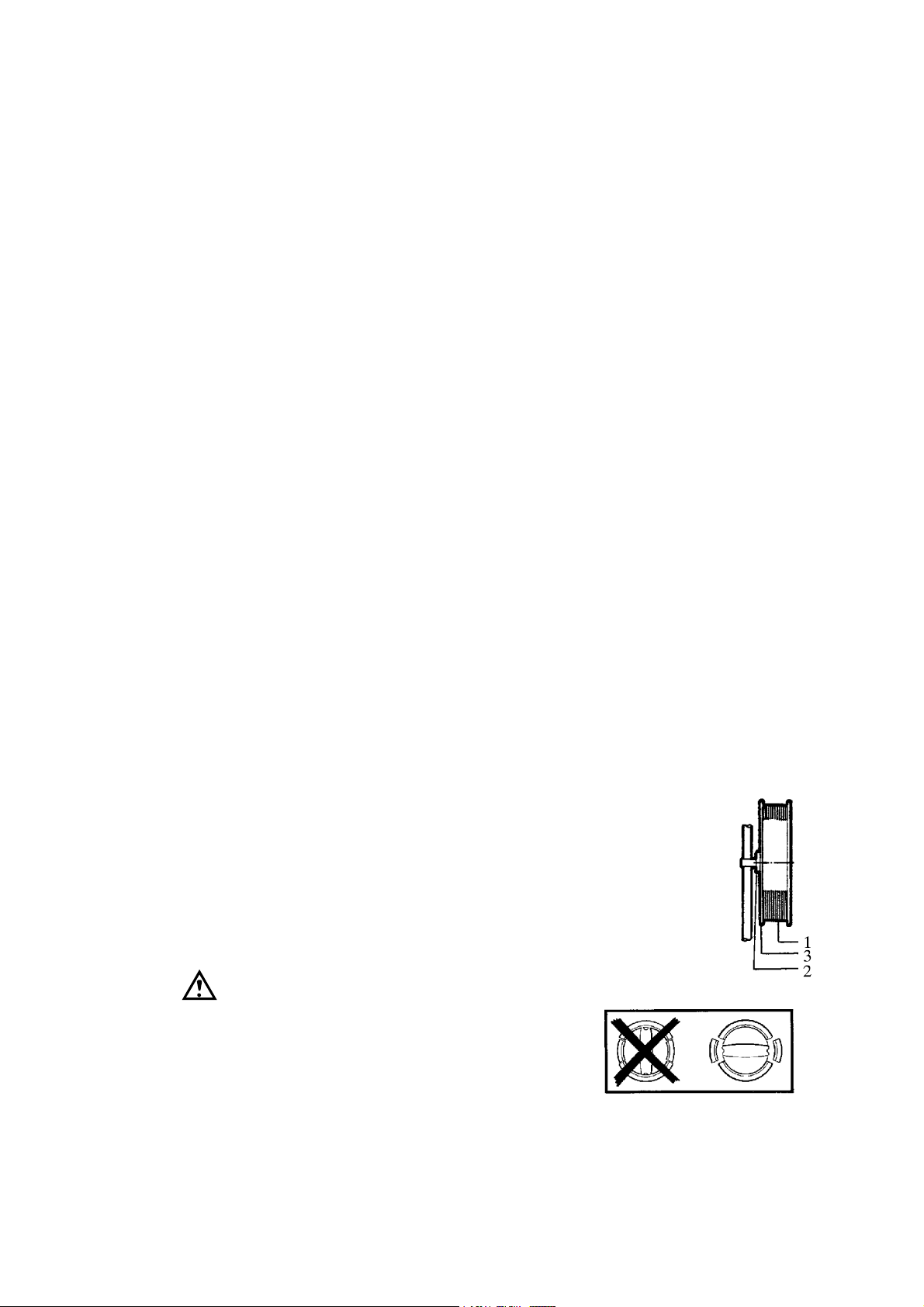
Loading with wire
1. Replacement of the coil
S Remove the wire reel from the brake hub (2) and take off one end (3).
S Place the coil (1) of wire on the reel and replace the end (3)
S Fit the wire reel or disposable reel on the brake hub (2):
Note the position of the carrier
IMPORTANT!
To prevent the wire drum from slipping off the
brake hub; Secure the drum with the red retaining knob,
as shown on the warning lable (right) by the brake hub.
cfa4i1ea
-- 1 0 --

OPERATION
1. Adjusting the braking torque
S Turn the release knob (006) to the
locked position.
S Insert a screwdriver into the
hubs springs.
S Turn the springs (002) clockwise to
reduce the braking torque, or anti--clockwise to increase it.
NB: adjust all springs by the same amount.
2. Check that the feed roller (1) and contact jaws
are of the correct size for the wire to be used.
S Replacement of the feed roller
S Remove knobs (5) and (6)
S Remove the handwheel (2)
S Replacement of the contact jaws
S Remove the pressure screw (3)
S Remove the lower, loose, half of the
contact tube
3. If the wire diameter is greater than 2 mm, straighten
out about 0.5 m of the wire and feed it through the wire
straightener by hand.
4. Adjust the pressure between the wire and the feed roller
by means of knob (6).Do not apply a higher pressure
than needed. The sprung knob (6) must not be tightened
down fully to the bottom, but some spring action must
be left
aza5dp08
3
dfa3d002
5. Connect the welding power source to the mains supply.
Feed out 30 mm of wire using switch A 02 on the PEG1 control box.
6. Straighten out the wire using knob (5). When welding with thin wire, the wire should
remain straight over a distance of about 25 mm beyond the contact device, and with thick
wire over a distance of about 45 mm.
7. Tighten the contact device pressure screw (3). Note that this screw must be bottomed in
order to avoid play between the contact jaws. (This applies only to submerged -arc welding).
Filling with flux (A6 TFD1 and A6 TFD2)
1. Close the valve on the flux hopper
2. Remove the separating cyclone of the flux recovery unit, if fitted. Fill the hopper with
flux, which must be dry
3. Adjust the height of the flux discharge nozzle above the weld to obtain a suitable depth of
flux
cfa4i1ea
-- 1 1 --

Conversion of the A6 TFD1 (submerged--arc welding) to MIG/MAG--welding
1. Replace the wire feed gear motor unit.
2. Make the necessary changes to the PEG 1 control unit as described in the PEG1 instruction manual.
Operating instructions for the PEG1 control box
1. Position the carriage at the starting position, with switch A 06 set to position 3.
2. Cut off the tip of the wire on the skew.
3. Feed the wire to the proximity of the workpiece by means of switch A.
4. Set switch A 07 to position 3. ”Presetting”.
5. Preset a suitable welding current by means of potentiometer A 01.
6. Preset a suitable travel speed by means of potentiometer A 05.
7. If the welding power source is fitted with a preselection device, set a suitable welding
voltage by means of potentiometer A 03.
8. Set switch A 07 to position 2.. ”Current feedback”.
9. Select the required starting mode and direction of travel by means of switch A 06,
(Position1,automatic start; position 2, scrape start; position 3, manual start).
10. Position the flux discharge tube to ensure good flux coverage, and open the fluxvalve (for
submerged--arc welding).
11. Start welding by pressing pushbutton A 08 until indicating l amp A 08 lights.
12. If the welding power source is not fitted with a preselection device, adjust the welding
voltage by means of switch A 04.
13. With switch A 07 in position 1, ”Voltage feedback”, during welding, welding current cannot be preset as described above under item 4. Instead, it should be adjusted by means of
potentiometer A 01 after welding has started.
14. Adjust the post --burn time by means of potentiometer A 22 on the back of the control
unit.
15. Terminate welding by means of pushbutton A 09.
16. Close the flux valve on conclusion of welding (submerged--arc welding).
cfa4i1ea
-- 1 2 --

MAINTENANCE
PEG1 control box, see instruction manual 333 470--001.
A6 VEC wire feed motor, see instruction manual 333 533--003.
Daily
S Clean dust and welding residue away from the moving parts of the machine.
S Check that all hoses and electrical connections are undamaged and correctly connected.
S Check that all screws and bolted joints are tight.
S Check the braking torque of the brake hub. This must not be so low that the wire reel
continues to rotate when wire feed stops, nor so high that the feed roller slips. A guide
value for a 30 kg reel is 1.5 Nm.
Periodic
S Inspect the wire feed motor brushes at three--monthly intervals, and replace them when
they are worn down to 6 mm.
S Lubricate adjustment slides as necessary.
S Check the wire feed unit’s wire guide, drive rollers and contact tip, and replace if worn or
damaged.
S Check that the chain is correctly tensioned and lubricate if necessary.
S Check that the drive motor runs correctly at maximum, normal and minimum speeds.
If the motor runs unevenly, it indicates that the brushes are worn and that the entire motor
must be replaced.
cfa4i1ea
-- 1 3 --

TROUBLESHOOTING
Equipment
S Manual for control box PEG1, order no. 333 470-001.
S Manual for motor with gear A6 VEC, order no. 333 533-003.
Check
S that the welding power supply is connected for the correct mains
supply voltage
S that all three phases are l ive (phase sequence is immaterial)
S that all welding cables and connections are undamaged
S that all controls are correctly set
S that the mains power supply is disconnected before repairs are done
on the machine
POSSIBLE FAULTS
1. Symptom Wide variations of current and voltage display values.
Cause 1.1 The contact jaws or contact tip are worn or of the wrong size.
Action Replace contact jaws or contact tip as necssary.
Cause 1.2 Insufficient pressure on feed rollers.
Action Increase feed roller pressure.
2. Symptom Wire feed is irregular.
Cause 2.1 The pressure on the wire feed rollers is incorrectly set.
Action Adjust feed roller pressure.
Cause 2.2 Wrong size of feed rollers.
Action Replace feed rollers.
Cause 2.3 The grooves in the feed rollers ar worn.
Action Replace feed rollers.
3. Symptom Power supply cables overheat.
Cause 3.1 Poor electrical connections.
Action Clean and tighten all electrical connections.
Cause 3.2 Inadequately sized cables.
Action Use larger cables or fit parallel cables.
4. Symptom Contact jaws are burnt or destroyed.
Cause 4.1 The spring-loaded pressure screw in the contact device is not bearing
properly against the contact jaws, causing arching between the contact jaws
and the wire.
Action Replace the pressure screw.
cfa3f1ea
-- 1 4 --

DIMENSION DRAWING
A6 TFD1
A Butt welding B Fillet welding
dfa4m01b
dfa4m01a
cfa4m11a
-- 1 5 --

DIMENSION DRAWING
A6 TFD2
dfa4m02a
cfa4m11a
dfa4m02b
-- 1 6 --

DIAGRAM
A6 TFD1/TFD2
01. Welding power source (DC)
02. Control box
03. Motor with gear
04. Straightener
05. Connector
06. Contact tube
07. Welding cable
08. Control cable
09. Cable
10. Welding power source (AC)
11. Filler wire unit
A6 TGD1
01. Welding power source (DC)
02. Control box
03. Motor with gear
04. Straightener
05. Connector
06. Solenoid valve
07. Reducer valve
08. Welding cable
09. Gas bottle
10. Hose (Gas)
11. Cooling unit
12. Hose (Cooling water)
13. Hose coupling
14. Hose (Cooling water)
15. Control cable
16. Cable
17. Hose (Gas)
cfa4e11a
dfa4sch2
-- 1 7 --

cfa4e11a
-- 1 8 --
 Loading...