

ESAB A2, A6 Instruction Manual

Instruction manual
0460 949 274 GB 20151222 Valid for: from program version 4.10A
A2, A6 PEK Control Panel

TABLE OF CONTENTS
0460 949 274 © ESAB AB 2015
1 INTRODUCTION................................................................................................... 5
1.1 Control panel ........................................................................................................ 5
1.1.1 Keys and knobs.................................................................................................. 6
1.2 First step ............................................................................................................... 7
1.2.1 Choice of language ............................................................................................7
1.2.2 Unit of measurements ........................................................................................ 9
1.3 Display ................................................................................................................ 10
1.3.1 Symbols in the display ..................................................................................... 11
1.4 General information about settings ................................................................. 11
1.4.1 Setting of numerical values .............................................................................. 11
1.4.2 Setting with given alternatives.......................................................................... 11
1.5 QUIT and ENTER ................................................................................................12
2 MENUS ............................................................................................................... 13
2.1 Main Menu........................................................................................................... 13
2.1.1 Configuration menu..........................................................................................14
2.1.2 Tools menu.......................................................................................................14
2.1.3 Weld data setting menu ...................................................................................15
2.1.4 Measurements menu .......................................................................................16
2.1.5 Weld data memory menu ................................................................................. 17
2.1.6 Fast mode menu ..............................................................................................18
3 SUBMERGED ARC WELDING .......................................................................... 19
3.1 Settings for submerged arc welding ................................................................ 19
4 GAS METAL ARC WELDING.............................................................................21
4.1 Settings for Gas Metal Arc Welding .................................................................21
5 GOUGING ........................................................................................................... 23
5.1 Settings for gouging ..........................................................................................23
6 FUNCTION EXPLANATIONS............................................................................. 25
6.1 CA, constant amperage .....................................................................................25
6.2 CW, constant wire feed......................................................................................25
6.3 CC, constant current..........................................................................................25
6.4 Wire / electrode dimension ...............................................................................25
6.5 Arc voltage.......................................................................................................... 25
6.6 Wire feed speed..................................................................................................25
6.7 Cold wire feed speed (ICE) ................................................................................25
6.8 Cold wire start delay (ICE)................................................................................. 25
6.9 Travel speed .......................................................................................................26
6.10 Welding direction ............................................................................................... 26
6.11 AC frequency......................................................................................................26
6.12 AC balance.......................................................................................................... 26

TABLE OF CONTENTS
0460 949 274 © ESAB AB 2015
6.13 AC offset .............................................................................................................26
6.14 Flux pre-flow (SAW) ...........................................................................................26
6.15 Gas pre-flow (GMAW) ........................................................................................26
6.16 Air pre-flow (Gouging) .......................................................................................26
6.17 Start type............................................................................................................. 26
6.18 Wire creep start ..................................................................................................27
6.19 Start phases........................................................................................................ 27
6.20 Max Open Circuit Voltage (OCV)....................................................................... 27
6.21 Flux post-flow (SAW) .........................................................................................27
6.22 Gas post-flow (GMAW) ......................................................................................27
6.23 Air post-flow (Gouging) .....................................................................................27
6.24 Crater filling ........................................................................................................ 28
6.25 Burnback time ....................................................................................................28
6.26 Stop phases........................................................................................................28
6.27 Dynamic regulation ............................................................................................28
6.28 Control parameters ............................................................................................ 28
6.29 Setting limits....................................................................................................... 29
6.30 Measure limits ....................................................................................................29
7 MEMORY MANAGEMENT ................................................................................. 30
7.1 Control panel working method .........................................................................30
7.2 Store .................................................................................................................... 31
7.3 Recall................................................................................................................... 32
7.4 Delete .................................................................................................................. 33
7.5 Copy ....................................................................................................................34
7.6 Name ................................................................................................................... 36
7.7 Edit ...................................................................................................................... 37
8 CONFIGURATION MENU...................................................................................39
8.1 Code lock ............................................................................................................ 39
8.1.1 Lock code status ..............................................................................................39
8.1.2 Specify/edit lock code ......................................................................................40
8.2 General configuration ........................................................................................40
8.2.1 Fast mode soft keys ......................................................................................... 41
8.2.2 Quality data log to file....................................................................................... 42
8.2.3 Soft key configuration....................................................................................... 42
8.2.4 Auto save mode ...............................................................................................44
8.3 Machine configuration .......................................................................................44
8.3.1 Product code .................................................................................................... 44
8.3.2 Wire feed axis ..................................................................................................45
8.3.3 Cold wire axis (ICE) .........................................................................................45

TABLE OF CONTENTS
0460 949 274 © ESAB AB 2015
8.3.4 Travel axis........................................................................................................46
8.3.5 Outer axis.........................................................................................................46
8.3.6 Tandem for LAF and TAF power sources.........................................................47
8.3.7 Tandem for Aristo 1000 power source .............................................................50
8.3.8 Parallel power sources (applies only to Aristo 1000 power sources)...............51
8.3.9 Ice wire feed.....................................................................................................52
8.3.10 Polarity (applies only to Aristo 1000 power source) ......................................... 53
8.3.11 Node id settings (applies only to Aristo 1000 power source) ...........................54
8.3.12 System information (applies only to Aristo 1000 power source) ......................54
8.4 Cable lengths (applies only to LAF and TAF power sources) .......................54
8.5 Maintenance ....................................................................................................... 55
8.6 Measure–values filter factor..............................................................................55
9 TOOLS ................................................................................................................ 56
9.1 Event handling ................................................................................................... 56
9.1.1 Event log ..........................................................................................................56
9.1.2 Active errors ..................................................................................................... 57
9.1.3 Unit IDs ............................................................................................................57
9.1.4 Description of fault management codes...........................................................58
9.2 Export/Import...................................................................................................... 59
9.3 File manager ....................................................................................................... 60
9.3.1 Delete a file/folder ............................................................................................61
9.3.2 Rename a file/folder ......................................................................................... 61
9.3.3 Create new folder.............................................................................................62
9.3.4 Copy and paste files......................................................................................... 62
9.4 Setting limit editor..............................................................................................63
9.5 Measure limits editor .........................................................................................63
9.6 Production statistics.......................................................................................... 65
9.7 Quality functions ................................................................................................65
9.7.1 Store quality data .............................................................................................66
9.8 Calendar..............................................................................................................67
9.9 User accounts .................................................................................................... 67
9.10 Unit information ................................................................................................. 69
MENU STRUCTURE..................................................................................................70
WIRE DIMENSION.....................................................................................................75
ORDERING NUMBERS ............................................................................................. 76
Rights reserved to alter specifications without notice.

1 INTRODUCTION
0460 949 274
- 5 -
© ESAB AB 2015
1 INTRODUCTION
To benefit as much as possible from your welding equipment, we recommend that you read
this instruction manual.
For general information about operation, see the instruction manual for the control unit,
automatic welding machine, column and boom or power source.
The text presented in the display is available in the following languages: English, Swedish,
Finnish, Norwegian, Danish, German, French, Italian, Dutch, Spanish, Portuguese,
Hungarian, Polish, American, Czech, Chinese and Russian.
1.1 Control panel
1. Menu
2. Knob for moving cursor (positioning
knob)
3. ENTER
4. Green indicating lamp, illuminates
when the function is active
5. Welding start
6. Welding stop
7. Knob for setting the travel speed in
the measurements menu, in other
menus to increase or decrease the
set values (setting knob)
8. Manual travel motion
9. Manual wire feed downwards
10. Knob for setting the arc voltage in the measurement menu, in other menus to increase
or decrease the set values (setting knob)
11. Fast motion
12. Manual travel motion
13. Knob for setting the welding current / wire feed speed in the measurements menu, in
other menus to increase or decrease the set values (settings knob)
14. Emergency stop
15. Manual wire feed upwards

1 INTRODUCTION
0460 949 274
- 6 -
© ESAB AB 2015
16. Soft keys
17. Display
1.1.1 Keys and knobs
Menu
The Menu key always takes you back to the main menu in the relevant process:
ENTER
Use the ENTER key to confirm a selection.
Soft keys
The five keys (S1 - S5) under the display have different functions. They are called ”soft” keys,
i.e. they can have different functions depending on which menu you are in. The current
function for these keys can be seen from the text in the bottom row of the display. When the
function is active, this is indicated by the field with the text box turning white.
Wire feed upwards
Key for reversing the wire without arc voltage, when replacing wire bobbin for example. The
wire is fed as long as the button is depressed.
Wire feed downwards
Key for feeding wire without arc voltage. The wire is fed as long as the button is depressed.
Travel motion
Key for travel motion in the direction of welding where the symbol is indicated on the weld
equipment. To stop travel motion press , or .
The LED illuminates during travel motion.

1 INTRODUCTION
0460 949 274
- 7 -
© ESAB AB 2015
Travel motion
Key for travel motion in the direction of welding where the symbol is indicated on the weld
equipment. To stop travel motion press , or .
The LED illuminates during travel motion.
Welding start
Key for welding start.
Welding stop
Key for welding stop for all travel motions and all motors.
Positioning knob
The uppermost right-hand knob is called the positioning knob in the instruction manual and is
used to position the cursor.
Settings knob
The three knobs under the panel are called settings knobs in the instruction manual and are
used to change the set values in the panel.
1.2 First step
1.2.1 Choice of language
This menu appears when the machine is first started:
The control panel is set to English on delivery. To select your language, proceed as follows:
Press Menu to access the main menu.

1 INTRODUCTION
0460 949 274
- 8 -
© ESAB AB 2015
Position the cursor on the CONFIGURATION row, using the positioning knob.
Press ENTER to confirm the selection.
Position the cursor on the LANGUAGE row. Press ENTER to bring up a list of the languages
that are available in the control panel.
Position the cursor on the row for your language and press ENTER.

1 INTRODUCTION
0460 949 274
- 9 -
© ESAB AB 2015
1.2.2 Unit of measurements
The control panel is set to metric measurement on delivery. To select another mesurement,
proceed as follows:
Press Menu to access the main menu.
Position the cursor on the CONFIGURATION row, using the positioning knob.
Press ENTER to confirm the selection.
Position the cursor on the GENERAL CONFIGURATION row.
Press ENTER to confirm the selection.

1 INTRODUCTION
0460 949 274
- 10 -
© ESAB AB 2015
Position the cursor on the UNIT OF LENGTH row. Press ENTER to bring up a list of the
mesurements that are available in the control panel.
Position the cursor on the row for correct
mesurement and press ENTER.
1.3 Display
Cursor
The control panel's cursor is presented as a black field around the text, with the selected text
turning white. The cursor is displayed in the instruction manual with bold text
Text boxes
At the bottom of the display are five boxes containing text that describes the current function
of the five soft keys below the display.

1 INTRODUCTION
0460 949 274
- 11 -
© ESAB AB 2015
1.3.1 Symbols in the display
A The selected weld data set
B Welding direction
C A fault has occurred, see
“Event handling”, page56.
D Recalled memory position
number
E Scroll bar. Further information
can be found in this menu
Arrows
Where there is more information behind a row, this is indicated with a black arrow behind
the text.
1.4 General information about settings
There are three types of setting:
• Setting of numerical values
• Setting of given alternatives
• Setting of ON/OFF mode
1.4.1 Setting of numerical values
The settings knobs are used to increase or decrease the set values when setting numerical
values. In the measurements menu, the knobs for welding current / wire feed speed, arc
voltage or travel motion are used.
1.4.2 Setting with given alternatives
Some settings are made by selecting an option from a list. This is an example of the list:
The cursor is positioned on the row for SAW. By pressing ENTER in this position, the SAW
option is selected. If you want to choose another option instead, position the cursor on the
correct row by scrolling up or down using the positioning knob. Then press ENTER. If you
want to exit the list without making a selection, press QUIT.

1 INTRODUCTION
0460 949 274
- 12 -
© ESAB AB 2015
1.5 QUIT and ENTER
The “soft” key farthest to the right is used primarily for QUIT, although it is occasionally used
for other functions.
• QUIT returns you to the previous menu or image.
• Pressing ENTER entails the execution of a selected choice in a menu or a list.
The key is called ENTER in this manual.

2 MENUS
0460 949 274
- 13 -
© ESAB AB 2015
2 MENUS
The control panel uses several different menus:
• Main menu
• Configuration menu
• Tools menu
• Weld data setting menu
• Measurements menu
• Weld data memory menu
• Fast mode menu
The menu trees are displayed in the "MENU STRUCTURE" appendix to this manual. During
start-up, a start-up screen containing information about the current program version is
displayed briefly.
Start-up screen
2.1 Main Menu
In the MAIN MENU, you can change welding process, method, wire type, control method,
wire dimension etc.
You can access other sub menus from this menu.
2 MENUS
0460 949 274
- 14 -
© ESAB AB 2015
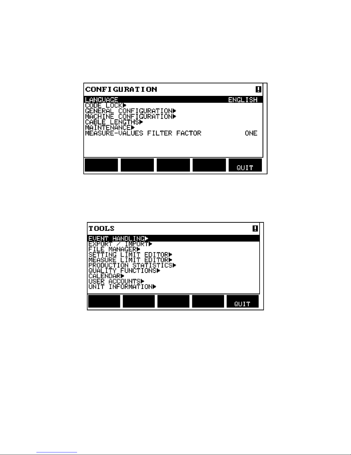
2.1.1 Configuration menu
Main menu → Configuration
In the CONFIGURATION menu it is possible to change language, change password, make
General configuration, make machine adjustments etc.The menu has different appearances
depending on which power source type is selected under Machine configuration.
2.1.2 Tools menu
Main menu → Tools
In the TOOLS menu you can transfer files, view quality and production statistics, event logs,
etc.

2 MENUS
0460 949 274
- 15 -
© ESAB AB 2015
2.1.3 Weld data setting menu
Main menu →
In the weld data setting menu, SET, it is possible to change different welding parameters.
The menu has different appearances depending on which welding process is selected.
Another example of the menu:

2 MENUS
0460 949 274
- 16 -
© ESAB AB 2015
2.1.4 Measurements menu
Main menu →
In MEASURE, you can view measured values for various welding parameters while welding
is in progress.
• A 450 AMP - Measured welding current
• 30.0 Volt - Measured arc voltage
• 50 cm/min - Measured travel speed
• 300 cm/min - Measured wire speed
• 30 kJ/cm - Indicates energy per unit length, which is obtained using the values selected
for welding current, arc voltage and travel speed
• 300 cm/min - Measured cold wire feed speed
The measured values remain in the display even after welding has been completed.
You can move to different menus without losing the measurement values.
The settings knobs can be used to change the welding parameters in the measurement
display.

2 MENUS
0460 949 274
- 17 -
© ESAB AB 2015
If the set value is changed when welding is not in progress, the measurement value
changes to zero.
For activating cold wire feed, a soft key, ICE WF, is activated, see “Soft key configuration”,
page42. When the key is depressed, the cold wire speed is changed using the left
settings knob A. If the soft key is not depressed, the settings knob affects the A current.
In the measurement display one can also see the set values if the soft key SET VALUES is
activated. If both soft keys, ICE WF and SET VALUES are activated, the set feed speed for
cold wire can be changed. For activating see “Soft key configuration”, page42.
• 300 cm/min - Set wire feed speed
• 20.0 Volt - Set arc voltage
• 30 cm/min - Set travel speed
2.1.5 Weld data memory menu
Main menu →
In the WELD DATA MEMORY menu you can store, recall, delete and copy various set weld
data. The weld data sets can be stored in 255 different memory positions.
For further information, see “MEMORY MANAGEMENT”, page30.

2 MENUS
0460 949 274
- 18 -
© ESAB AB 2015
2.1.6 Fast mode menu
Main menu →
In the FAST MODE menu, you can “link” soft keys to weld data memory positions. These
settings are carried out in the Configuration menu. The number of the selected memory
position is displayed in the top right corner.
For further information, see “Fast mode soft keys”, page41.

3 SUBMERGED ARC WELDING
0460 949 274
- 19 -
© ESAB AB 2015
3 SUBMERGED ARC WELDING
Main menu -> Process
During Submerged Arc Welding (SAW), an arc melts a continuously supplied wire. The weld
pool is protected by flux.
When the SAW process is selected, you can choose between two methods by marking
METHOD using the positioning knob and pressing ENTER. Choose between AC or DC.
When the SAW process is selected, you can choose between three control methods by
marking REGULATION TYPE using the positioning knob and pressing ENTER. Choose
between constant welding current CA or constant wire feed CW or constant current CC
(CCapplies only to Aristo1000), see explanations in “CA, constant amperage”, page25,
“CW, constant wire feed”, page25 and “CC, constant current”, page25.
If Ice wire feed is selected, see “Ice wire feed”, page52, only regulation type CW can be
selected.
3.1 Settings for submerged arc welding
Settings Setting range In steps of Value after
resetting
Arc voltage
1)
14 - 50 V 0.1 V (1V) 30 V
Welding current1)(CA)
0 - 3200 A 1 A 400 A
Wire feed speed1)(CW)
0 - 2500 cm/min 1 cm/min 300 cm/min
Constant current
1) 3)
(CC)
0 - 3200 A 1 A 400 A
Cold wire feed speed1)(CW)
0 - 2500 cm/min 1 cm/min 300 cm/min
Cold wire start delay1)(CW)
0 - 99,0 s 0,1 s 2,5 s
Travel speed* 0 - 200 cm/min 1 cm/min 50 cm/min
Welding direction ▲-■ - ■
AC frequency 10 - 100 Hz 1 50 Hz
AC balance 25 - 75% 1 50%
AC offset -300 - +300 A/-10 - +10V 1 A / 0.1 V 0
Start data
2)
Flux pre-flow 0 - 99.0 s 0.1 s 0 s
Start type Direct or Scrape - Direct
Wire creep start Auto or Set speed - Auto
Wire creep start speed 0 - 1000 cm/min 1 cm/min 20 cm/min

3 SUBMERGED ARC WELDING
0460 949 274
- 20 -
© ESAB AB 2015
Settings Setting range In steps of Value after
resetting
Start phases OFF or ON - OFF
Open-circuit voltage OFF or ON - OFF
Maximum open-circuit voltage 5 - 60 V 0.1 V 50 V
Stop data
2)
Flux post-flow 0 - 99.0 s 0.1 s 0 s
Crater filling OFF or ON - OFF
Crater filling time 0 - 10 s 0.01 s 1 s
Burnback time 0 - 10 s 0.01 s 1 s
Stop phases OFF or ON - OFF
Control parameters
Dynamics Auto or Set values - Auto
Inductance Auto or Set values - Auto
Setting limits - - -
Measure limits - - -
1)
The setting range is dependent on the product used.
2)
The menu shows the settings that belong to the selected regulation type.
3)
Applies only to Aristo1000 power sources

4 GAS METAL ARC WELDING
0460 949 274
- 21 -
© ESAB AB 2015
4 GAS METAL ARC WELDING
The process is available for certain machine types.
Main menu → Process
During Gas Metal Arc Welding (GMAW), an arc melts a continuously supplied wire. The weld
pool is protected by shielding gas.
When the Gas Metal Arc Welding (GMAW) process is selected, you can choose between two
control methods by marking REGULATION TYPE using the positioning knob and pressing
ENTER. Choose between constant amperage CA or constant wire feed CW, see explanation
in “CA, constant amperage”, page25 and “CW, constant wire feed”, page25.
4.1 Settings for Gas Metal Arc Welding
Settings Setting range In steps of Value after
resetting
Arc voltage* 14 - 50 V 0.1 V (1V) 30 V
Welding current* (CA) 0 - 3200 A 1 A 400 A
Wire feed speed* (CW) 0 - 2500 cm/min 1 cm/min 300 cm/min
Travel speed* 0 - 200 cm/min 1 cm/min 50 cm/min
Welding direction ▲-■ - ■
Start data
Gas pre-flow 0 - 99.0 s 0.1 s 2.0 s
Start type Direct or Scrape - Direct
Wire creep start Auto or Set speed - Auto
Wire creep start speed 0 - 1000 cm/min 1 cm/min 20 cm/min
Start phases OFF or ON - OFF
Open-circuit voltage OFF or ON - OFF
Maximum open-circuit voltage 5 - 60 V 0.1 V 50 V
Stop data
Gas post-flow 0 - 99.0 s 0.1 s 2.0 s
Crater filling OFF or ON - OFF
Crater filling time 0 - 10 s 0.01 s 1 s
Burnback time 0 - 10 s 0.01 s 1 s
Stop phases OFF or ON - OFF
Dynamic regulation Auto or Set value - Auto

4 GAS METAL ARC WELDING
0460 949 274
- 22 -
© ESAB AB 2015
Settings Setting range In steps of Value after
resetting
Setting limits - - -
Measure limits - - -
*) The setting range is dependent on the product used.

5 GOUGING
0460 949 274
- 23 -
© ESAB AB 2015
5 GOUGING
The process is available for certain machine types.
Main menu → Process
With arc air gouging, a special electrode comprising a carbon rod with a copper casing is
used.
An arc is formed between the carbon rod and the work piece, which melts the material. Air is
supplied so that the melted material is blown away.
When the GOUGING process is selected, you can choose between two control methods by
marking REGULATION TYPE using the positioning knob and pressing ENTER. Choose
between constant amperage CA or constant wire feed CW, see explanation in “CA, constant
amperage”, page25 and “CW, constant wire feed”, page25.
5.1 Settings for gouging
Settings Setting range In steps of Value after
resetting
Arc voltage* 14 - 50 V 0.1 V (1V) 30 V
Welding current* (CA) 0 - 3200 A 1 A 400 A
Wire feed speed* (CW) 0 - 2500 cm/min 1 cm/min 300 cm/min
Travel speed* 0 - 200 cm/min 1 cm/min 40 cm/min
Welding direction ▲-■ - ■
Start data
Air pre-flow 0 - 99.0 s 0.1 s 0 s
Start type Direct or Scrape - Direct
Wire creep start Auto or Set speed - Auto
Wire creep start speed 0 - 1000 cm/min 1 cm/min 20 cm/min
Start phases OFF or ON - OFF
Open-circuit voltage OFF or ON - OFF
Maximum open-circuit voltage 5 - 60 V 0.1 V 50 V
Stop data
Air post-flow 0 - 99.0 s 0.1 s 0 s
Crater filling OFF or ON - OFF
Crater filling time 0 - 10 s 0.01 s 1 s
Burnback time 0 - 10 s 0.01 s 1 s

5 GOUGING
0460 949 274
- 24 -
© ESAB AB 2015
Settings Setting range In steps of Value after
resetting
Stop phases OFF or ON - OFF
Dynamic regulation Auto or Set value - Auto
Setting limits - - -
Measure limits - - -
*) The setting range is dependent on the product used.
 Loading...