


A2, A6 PEK Control Panel
Instruction manual
0460 949 474 GB 20210203
Valid for: From software version 5.00

TABLE OF CONTENTS
1
INTRODUCTION
1.1 Control panel
1.1.1 Keys and knobs.................................................................................... 5
1.2 First step
1.2.1 Choice of language .............................................................................. 6
1.2.2 Unit of measurements .......................................................................... 8
1.3 Display
1.3.1 Symbols in the display.......................................................................... 9
1.4 General information about settings
1.4.1 Setting of numerical values .................................................................. 10
1.4.2 Setting with given alternatives.............................................................. 10
1.5 QUIT and ENTER
2
MENUS
2.1 Main Menu
2.1.1 Configuration menu .............................................................................. 11
2.1.2 Tools menu........................................................................................... 12
2.1.3 Weld data setting menu........................................................................ 12
........................................................................................................
..........................................................................................
..........................................................................................
.................................................................................................
.....................................................................................................
......................................................
....................................................................................
...............................................................................................
5
5
6
9
10
10
11
11
2.1.4 Measurements menu............................................................................ 14
2.1.5 Weld data memory menu ..................................................................... 15
2.1.6 Fast mode menu .................................................................................. 15
3
SUBMERGED ARC WELDING
3.1 Settings for submerged arc welding
4
GAS METAL ARC WELDING
4.1 Settings for gas metal arc welding
5
ELECTRO SLAG WELDING
5.1 Settings for electro slag welding
6
GOUGING
6.1 Settings for gouging
7
FUNCTION EXPLANATIONS
7.1 CA, constant amperage
7.2 CW, constant wire feed
7.3 CC, constant current
7.4 Wire / electrode dimension
7.5 Arc voltage
7.6 Wire feed speed
7.7 ICE wire feed speed
7.8 ICE wire start delay
7.9 Travel speed
7.10 Welding direction
7.11 AC frequency
....................................................................................................
..............................................................................................
......................................................................................
............................................................................................
...................................................................................
..........................................................................................
...................................................................
....................................................
......................................................................
.......................................................
.......................................................................
..........................................................
..............................................................................
......................................................................
.........................................................................
..........................................................................
..............................................................................
....................................................................
...............................................................................
................................................................................
17
17
19
19
21
21
23
24
25
25
25
25
25
25
25
25
26
26
26
26
0460 949 474 © ESAB AB 2021

TABLE OF CONTENTS
7.12 AC balance
7.13 AC offset
7.14 Flux pre-flow (SAW)
7.15 Gas pre-flow (GMAW)
7.16 Start adjust
7.17 Air pre-flow (Gouging)
7.18 Start type
7.19 Wire creep start
7.20 Start phases
7.21 Max Open Circuit Voltage (OCV)
7.22 Flux post-flow (SAW)
7.23 Gas post-flow (GMAW)
7.24 Air post-flow (Gouging)
7.25 Crater filling
7.26 Burnback time
7.27 Stop phases
7.28 Dynamic regulation
7.29 Control parameters
7.30 Setting limits
7.31 Measure limits
7.32 PEK control unit as separate motor control
..............................................................................................
..................................................................................................
................................................................................
.............................................................................
..............................................................................................
...........................................................................
.................................................................................................
......................................................................................
............................................................................................
...........................................................
..............................................................................
...........................................................................
.........................................................................
............................................................................................
........................................................................................
............................................................................................
................................................................................
................................................................................
...........................................................................................
........................................................................................
........................................
26
26
26
26
26
27
27
27
27
27
27
28
28
28
28
28
28
29
29
29
29
8
MEMORY MANAGEMENT
8.1 Control panel working method
8.2 Store
8.3 Recall
8.4 Delete
8.5 Copy
8.6 Name
8.7 Edit
9
CONFIGURATION MENU
9.1 Code lock
9.1.1 Lock code status .................................................................................. 39
9.1.2 Specify/edit lock code........................................................................... 40
9.2 General configuration
9.2.1 Fast mode soft keys ............................................................................. 40
9.2.2 Quality data log to file........................................................................... 41
9.2.3 Soft key configuration........................................................................... 41
9.2.4 Auto save mode ................................................................................... 43
9.3 Machine configuration
........................................................................................................
.......................................................................................................
.......................................................................................................
.........................................................................................................
........................................................................................................
...........................................................................................................
................................................................................................
..........................................................................
..............................................................
............................................................................
............................................................................
...........................................................................
33
33
33
34
35
36
37
37
39
39
40
43
9.3.1 Product code ........................................................................................ 44
9.3.2 Wire feed axis....................................................................................... 45
9.3.3 Cold wire axis (ICE).............................................................................. 46
0460 949 474 © ESAB AB 2021

TABLE OF CONTENTS
9.3.4 Travel axis ............................................................................................ 46
9.3.5 External axis......................................................................................... 46
9.3.6 Tandem for LAF and TAF power sources............................................. 47
9.3.7 Tandem for Aristo® 1000 power source............................................... 50
9.3.8 Parallel power sources (applies only to Aristo® 1000 power sources) 52
9.3.9 ICE wire feed........................................................................................ 53
9.3.10 Step function ........................................................................................ 54
9.3.11 Intermittent welding ............................................................................. 56
9.3.12 Polarity (applies only to Aristo® 1000 power source)........................... 56
9.3.13 Node id settings (applies only to Aristo® 1000 power source)............. 56
9.3.14 System information (applies only to Aristo® 1000 power source)........ 56
9.4 Cable lengths (applies only to LAF and TAF power sources)
9.5 Maintenance
9.6 Measure–values filter factor
............................................................................................
..................................................................
............
57
57
57
10
TOOLS
10.1 Event handling
.........................................................................................................
........................................................................................
10.1.1 Event log .............................................................................................. 59
10.1.2 Active errors ......................................................................................... 60
10.1.3 Unit IDs................................................................................................. 60
10.1.4 Description of fault management codes ............................................... 60
10.2 Export/Import
10.3 File manager
..........................................................................................
...........................................................................................
10.3.1 Delete a file/folder ................................................................................ 64
10.3.2 Rename a file/folder ............................................................................. 65
10.3.3 Create new folder ................................................................................. 65
10.3.4 Copy and paste files............................................................................. 65
10.4 Setting limit editor
10.5 Measure limits editor
10.6 Production statistics
10.7 Quality functions
..................................................................................
.............................................................................
..............................................................................
....................................................................................
10.7.1 Store quality data ................................................................................. 69
10.7.2 Import system settings ......................................................................... 69
10.8 Calendar
10.9 User accounts
10.10 Unit information
..................................................................................................
.........................................................................................
......................................................................................
59
59
63
63
66
67
67
68
70
70
71
ORDERING NUMBERS
Rights reserved to alter specifications without notice.
0460 949 474 © ESAB AB 2021
.......................................................................................
73

1 INTRODUCTION
1 INTRODUCTION
To benefit as much as possible from your welding equipment, we recommend that you read
this instruction manual.
For general information about operation, see the instruction manual for the control unit,
automatic welding machine, column and boom or power source.
The text presented in the display is available in the following languages: English, US English,
Swedish, Finnish, Norwegian, Danish, German, French, Italian, Dutch, Spanish, Portuguese,
Hungarian, Polish, Czech, Turkish, Chinese, Korean and Russian.
Instruction manuals in other languages can be downloaded from the Internet: www.esab.com
1.1 Control panel
1. Menu 10. Arc voltage / Setting knob
2. Positioning knob, for moving cursor 11. Fast motion
3. Enter 12. Manual travel motion
4. Green indication lamp, illuminates
when the function is active
5. Welding start 14. Emergency stop
6. Welding stop 15. Manual wire feed upwards
7. Travel speed / Setting knob 16. Soft keys
8. Manual travel motion 17. Display
9. Manual wire feed downwards
13. Welding current / Wire feed speed /
Setting knob
1.1.1 Keys and knobs
Menu
The Menu key always takes you back to the main menu in the relevant process.
0460 949 474
- 5 -
© ESAB AB 2021

1 INTRODUCTION
Enter
Use the ENTER key to confirm a selection.
Soft keys
The five keys (S1 - S5) under the display have different functions. They are called soft keys,
i.e. they can have different functions depending on which menu you are in. The current
function for these keys can be seen from the text in the bottom row of the display. When the
function is active, this is indicated by the field with the text box turning white.
Wire feed upwards
Key for reversing the wire without arc voltage, when replacing wire bobbin for
example. The wire is fed as long as the button is depressed.
Wire feed downwards
Menu
Key for feeding wire without arc voltage. The wire is fed as long as the button is
depressed.
Travel motion
Key for travel motion in the direction of welding where the symbol is indicated on
the weld equipment. To stop travel motion press , or .
The LED illuminates during travel motion.
Welding start
Key for welding start.
Welding stop
Key for welding stop for all travel motions and all motors.
Positioning knob
The uppermost right-hand knob is the positioning knob and is used to position the cursor.
Settings knob
The three settings knobs are used to change the set values in the panel.
1.2 First step
1.2.1 Choice of language
This menu appears at first start:
0460 949 474
- 6 -
© ESAB AB 2021

1 INTRODUCTION
SAW: CA
NONE NONE GAS / FLUX NONE 2ND FUNCT
The control panel is set to English on delivery. To select your language, proceed as follows:
Press Menu to access the main menu.
Position the cursor on the CONFIGURATION row, using the positioning knob.
SAW
PROCESS
METHOD
REGULATION TYPE
WIRE TYPE
WIRE DIMENSION
SAW
DC
CA
Fe SOLID
3.0 mm
CONFIGURATION►
TOOLS►
SET MEASURE MEMORY FAST MODE
Press ENTER to confirm the selection.
Position the cursor on the LANGUAGE row. Press ENTER to bring up a list of the languages
that are available in the control panel.
CONFIGURATION
LANGUAGE
ENGLISH
CODE LOCK►
GENERAL CONFIGURATION►
MACHINE CONFIGURATION►
CABLE LENGTHS►
MAINTENANCE►
MEASURE-VALUES FILTER FACTOR
Position the cursor on the row for your language and press ENTER.
0460 949 474
- 7 -
ONE
QUIT
© ESAB AB 2021
1 INTRODUCTION
NORSK
POLSKI
PORTUGUES
SUOMI
SVENSKA
CHINESE
1.2.2 Unit of measurements
The control panel is set to metric measurement on delivery. To change measurement unit,
proceed as follows:
Press Menu to access the main menu.
Position the cursor on the CONFIGURATION row, using the positioning knob.
SAW
PROCESS
METHOD
REGULATION TYPE
WIRE TYPE
WIRE DIMENSION
CONFIGURATION►
TOOLS►
SET MEASURE MEMORY FAST MODE
Press ENTER to confirm the selection.
Position the cursor on the GENERAL CONFIGURATION row.
CONFIGURATION
LANGUAGE
CODE LOCK
GENERAL CONFIGURATION►
SAW
DC
CA
Fe SOLID
3.0 mm
ENGLISH
MACHINE CONFIGURATION►
CABLE LENGTHS►
MAINTENACE►
MEASURE-VALUES FILTER FACTOR
QUIT
Press ENTER to confirm the selection.
Position the cursor on the UNIT OF LENGTH row. Press ENTER to bring up a list of the
measurements that are available in the control panel.
0460 949 474
- 8 -
© ESAB AB 2021
ONE

1 INTRODUCTION
GENERAL CONFIGURATION
FAST MODE SOFT BUTTONS
QUALITY DATA LOG TO FILE
SOFT KEYS SETUP►
AUTO SAVE MODE
UNIT OF LENGTH
Position the cursor on the row for correct measurement and press ENTER.
METRIC
INCH.
1.3 Display
SAW
PROCESS
METHOD
1
ON
OFF
METRIC
QUIT
SAW
DC
REGULATION TYPE
WIRE TYPE
WIRE DIMENSION
Fe SOLID
CA
3.0 mm
CONFIGURATION►
TOOLS►
SET MEASURE MEMORY FAST MODE
Cursor
The control panel's cursor is presented as a black field around the text, with the selected text
turning white. The cursor is displayed in the instruction manual with bold text
Text boxes
At the bottom of the display are five boxes containing text that describes the current function
of the five soft keys below the display.
1.3.1 Symbols in the display
A The selected weld data set
B Welding direction
C A fault has occurred, see
section "Event handling".
0460 949 474
- 9 -
D Recalled memory position
number
E Scroll bar. Further information
can be found in this menu
© ESAB AB 2021
1 INTRODUCTION
Arrows
Where there is more information behind a row, this is indicated with a black arrow behind
the text.
SAW
PROCESS
METHOD
REGULATION TYPE
WIRE TYPE
WIRE DIMENSION
CONFIGURATION►
TOOLS►
SET MEASURE MEMORY FAST MODE
SAW
Fe SOLID
0.8 mm
1.4 General information about settings
There are three types of setting:
• Setting of numerical values
• Setting of given alternatives
• Setting of ON/OFF mode
1.4.1 Setting of numerical values
The settings knobs are used to increase or decrease the set values when setting numerical
values. In the measurements menu, the knobs for welding current / wire feed speed, arc
voltage or travel speed are used.
AC
CC
1.4.2 Setting with given alternatives
Some settings are made by selecting an option from a list. This is an example of the list:
SAW
GMAW
GOUGING
The cursor is positioned on the row for SAW. By pressing ENTER in this position, the SAW
option is selected. If you want to choose another option instead, position the cursor on the
correct row by scrolling up or down using the positioning knob. Then press ENTER. If you
want to exit the list without making a selection, press QUIT.
1.5 QUIT and ENTER
The soft key farthest to the right is used primarily for QUIT, although it is occasionally used
for other functions.
• QUIT returns you to the previous menu or image.
• Pressing ENTER entails the execution of a selected choice in a menu or a list.
The key is called ENTER in this manual.
0460 949 474
- 10 -
© ESAB AB 2021

2 MENUS
2 MENUS
The control panel uses several different menus:
• Main menu
• Configuration menu
• Tools menu
• Weld data settings menu SET
• Measurments menu MEASURE
• Weld data memory menu MEMORY
• Fast mode menu FAST MODE
During start-up, a start-up screen containing information about the current program version
is displayed briefly.
Start-up screen
2.1 Main Menu
In the MAIN MENU, you can change welding process, method, wire type, control method,
wire dimension etc.
You can access other sub menus from this menu.
SAW
PROCESS
METHOD
REGULATION TYPE
WIRE TYPE
WIRE DIMENSION
CONFIGURATION►
TOOLS►
SET MEASURE MEMORY FAST MODE
2.1.1 Configuration menu
Fe SOLID
3.0 mm
SAW
DC
CA
MAIN MENU » CONFIGURATION
In the CONFIGURATIONmenu it is possible to change language, change password, make
general configuration, make machine adjustments etc. The menu has different appearances
depending on which power source type is selected under MACHINE CONFIGURATION.
0460 949 474
- 11 -
© ESAB AB 2021
2 MENUS
CONFIGURATION
LANGUAGE
ENGLISH
CODE LOCK►
GENERAL CONFIGURATION►
MACHINE CONFIGURATION►
CABLE LENGTHS►
MAINTENANCE►
NETWORK SETTINGS
MEASURE-VALUES FILTER FACTOR
ONE
QUIT
2.1.2 Tools menu
MAIN MENU » TOOLS
In the TOOLS menu you can transfer files, view quality and production statistics, event logs,
etc.
TOOLS
EVENT HANDLING►
EXPORT / IMPORT►
FILE MANAGER►
SETTING LIMIT EDITOR►
MEASURE LIMIT EDITOR►
PRODUCT STATISTICS►
QUALITY FUNCTIONS►
CALENDAR►
USER ACCOUNTS►
UNIT INFORMATION►
QUIT
2.1.3 Weld data setting menu
MAIN MENU » SET
In the weld data setting menu, SET, it is possible to change different welding parameters.
The menu has different appearances depending on which welding process is selected.
0460 949 474
- 12 -
© ESAB AB 2021
2 MENUS
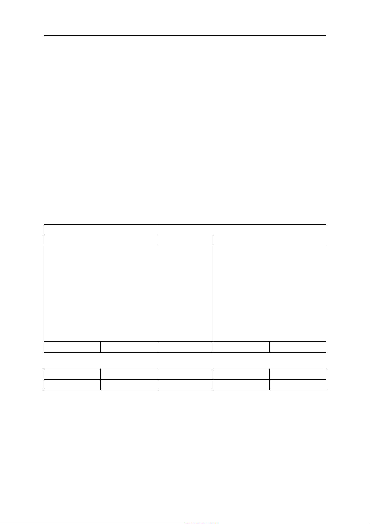
SAW WELD DATA SETTING
VOLTAGE
CURRENT
TRAVEL SPEED
DIRECTION
START DATA►
STOP DATA►
REGULATION PAR.►
SETTING LIMITS►
MEASURE LIMITS►
POLARITY
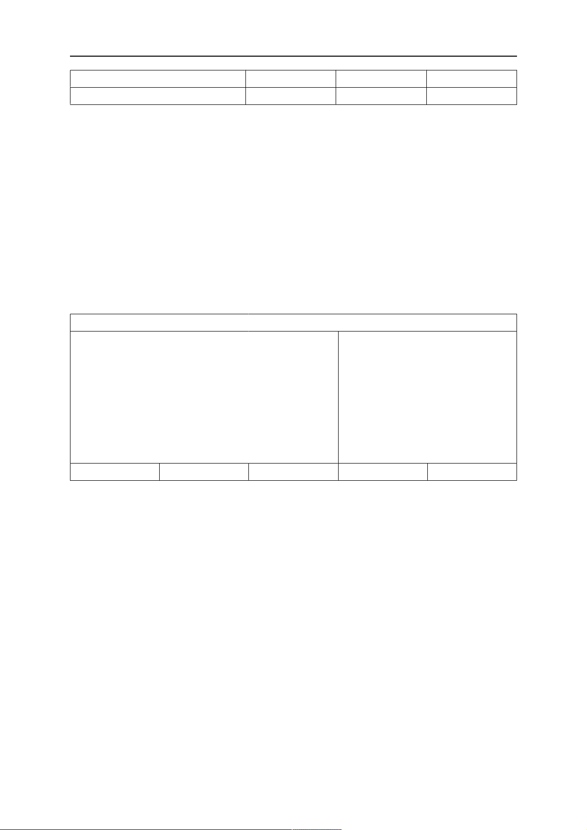
Another example of the menu with Aristo® 1000:
SAW WELD DATA SETTING
VOLTAGE
CURRENT
20.5 V
395 A
0 cm/min
■
AUTO
DC+
QUIT
24.0 V
3200 A
TRAVEL SPEED
DIRECTION
AC FREQUENCY
AC BALANCE
AC OFFSET
START DATA►
STOP DATA►
REGULATION PAR.►
Example of the menu with LAF/ TAF power source
30 cm/min
■
50 HZ
50%
0 V
QUIT
0460 949 474
- 13 -
© ESAB AB 2021

2 MENUS
SAW WELD DATA SETTING
VOLTAGE
CURRENT
TRAVEL SPEED
30.0 A
500 A
30 cm/min
DIRECTION
START DATA►
STOP DATA►
REGULATION PAR.►
SETTING LIMITS►
MEASURE LIMITS►
POLARITY
DC +
MEASURE QUIT
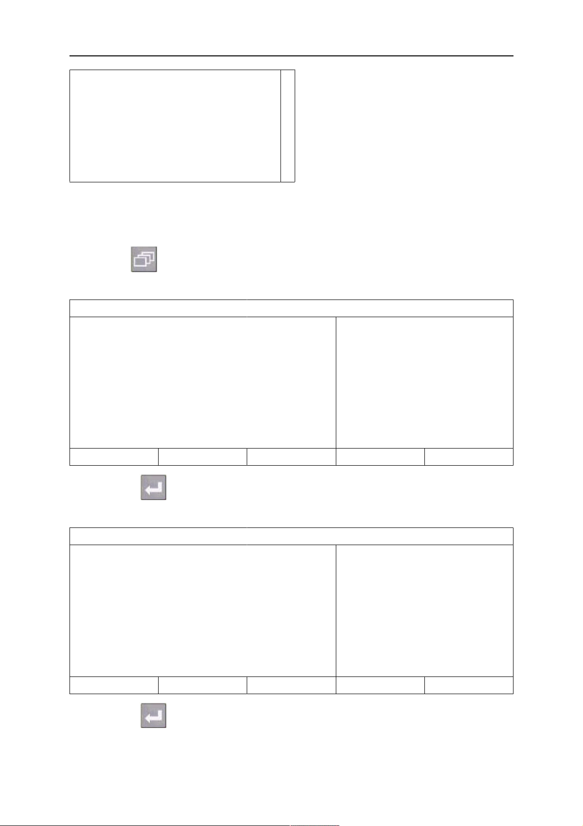
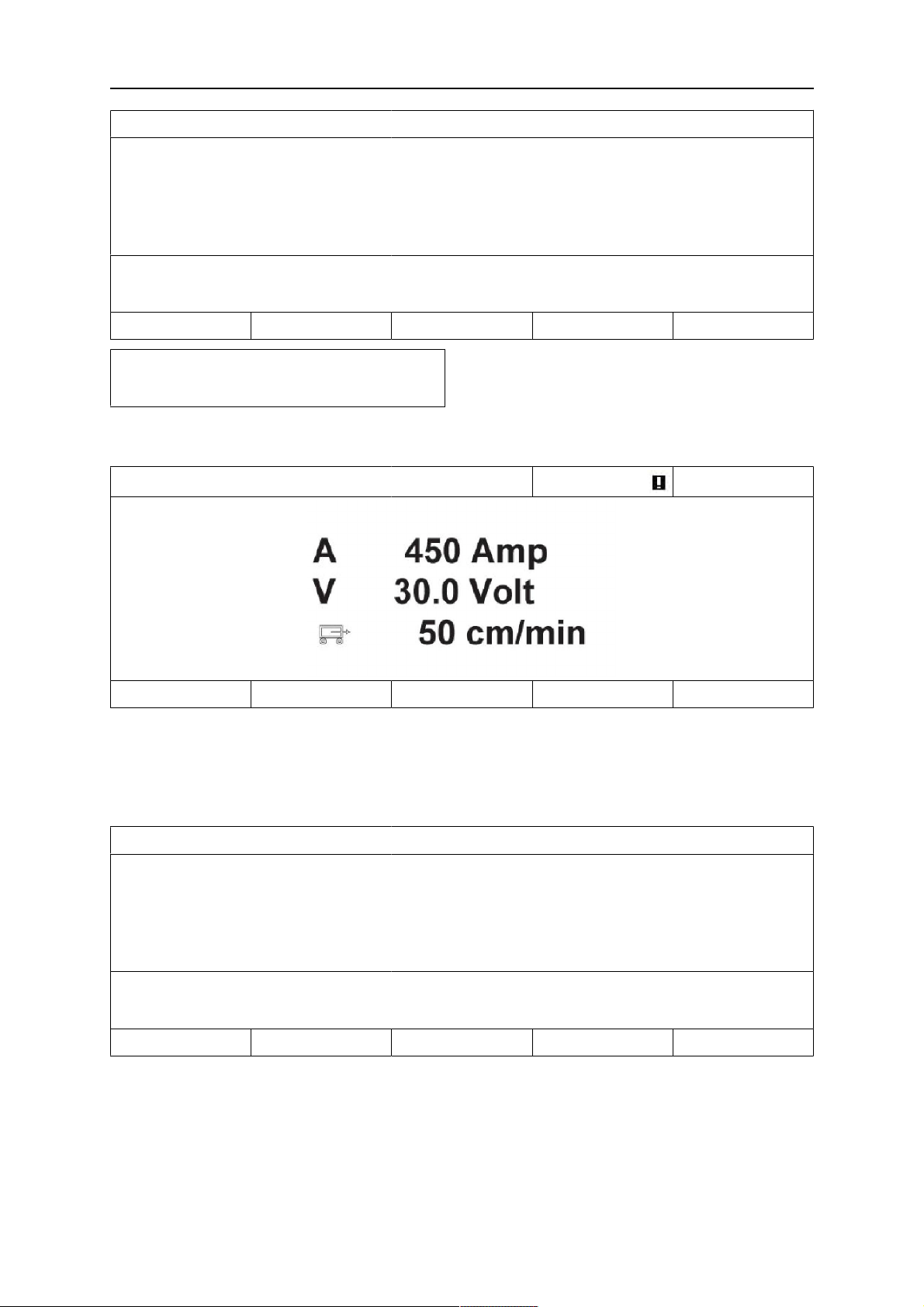
2.1.4 Measurements menu
MAIN MANU » MEASURE
In MEASURE menu, you can view measured values for various welding parameters while
welding is in progress.
■
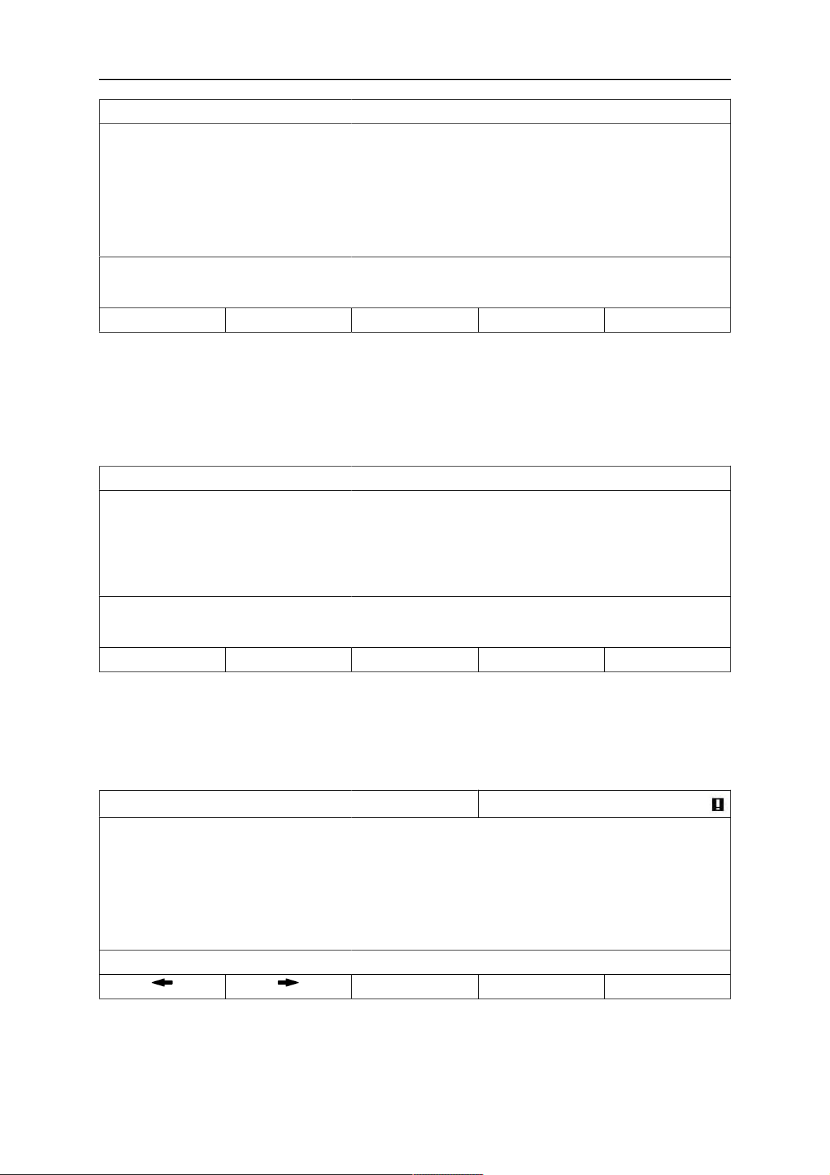
SAW: CA
EXT. AXIS DIR. SQUARE NONE SET VALUES 2ND FUNCT
• 450 Amp - Measured welding current
• 30.0 Volt - Measured arc voltage
• 50 cm/min - Measured travel speed
SAW: CA
NONE NONE ICE WF NONE 2ND FUNCT
• cm/min - Measured wire speed
• kJ/cm - Indicates energy per unit length, which is obtained using the values selected
for welding current, arc voltage and travel speed
0460 949 474
- 14 -
© ESAB AB 2021

2 MENUS
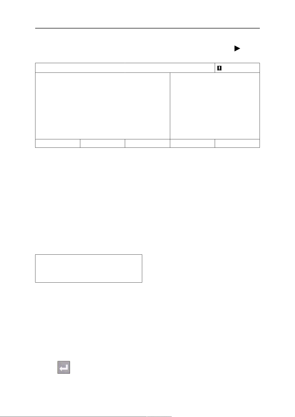
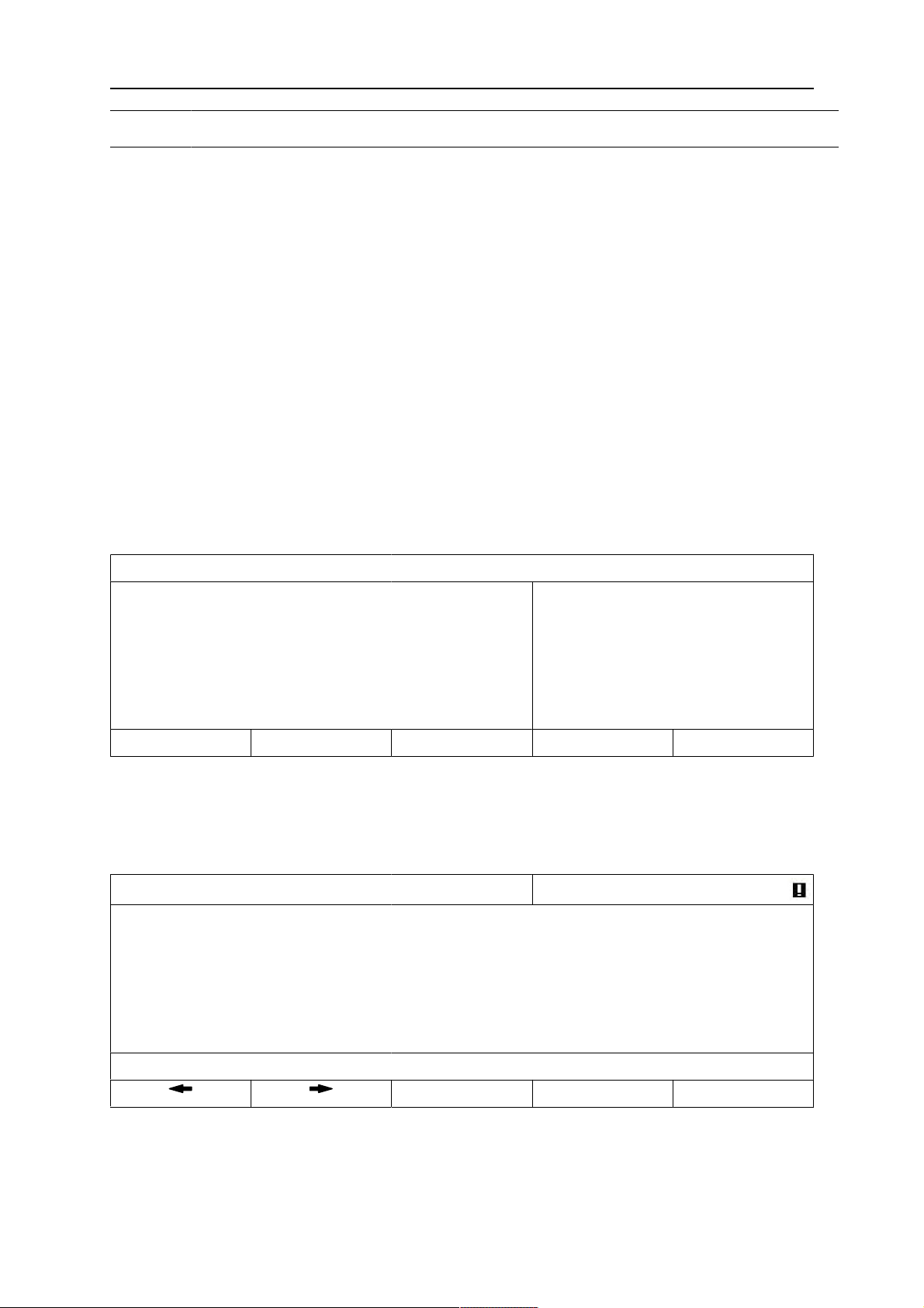
• cm/min - Measured ICE wire feed speed
• kg/h - Indicates used material per / hour
The measured values remain in the display even after welding has been completed.
You can move to different menus without losing the measurement values.
The settings knobs can be used to change the welding parameters in the measurement
display.
If the set value is changed when welding is not in progress, the measurement value changes
to zero.
For activating ICE wire feed, a soft key, ICE WF, is activated, see section "Soft key
configuration". When the key is depressed, the ICE wire speed is changed using the left
settings knob A. If the soft key is not depressed, the settings knob affects the A current.
In the measurement display one can also see the set values if the soft key SET VALUES is
activated. If both soft keys, ICE WF and SET VALUES are activated, the set feed speed for
cold wire can be changed. For activating see section "Soft key configuration".
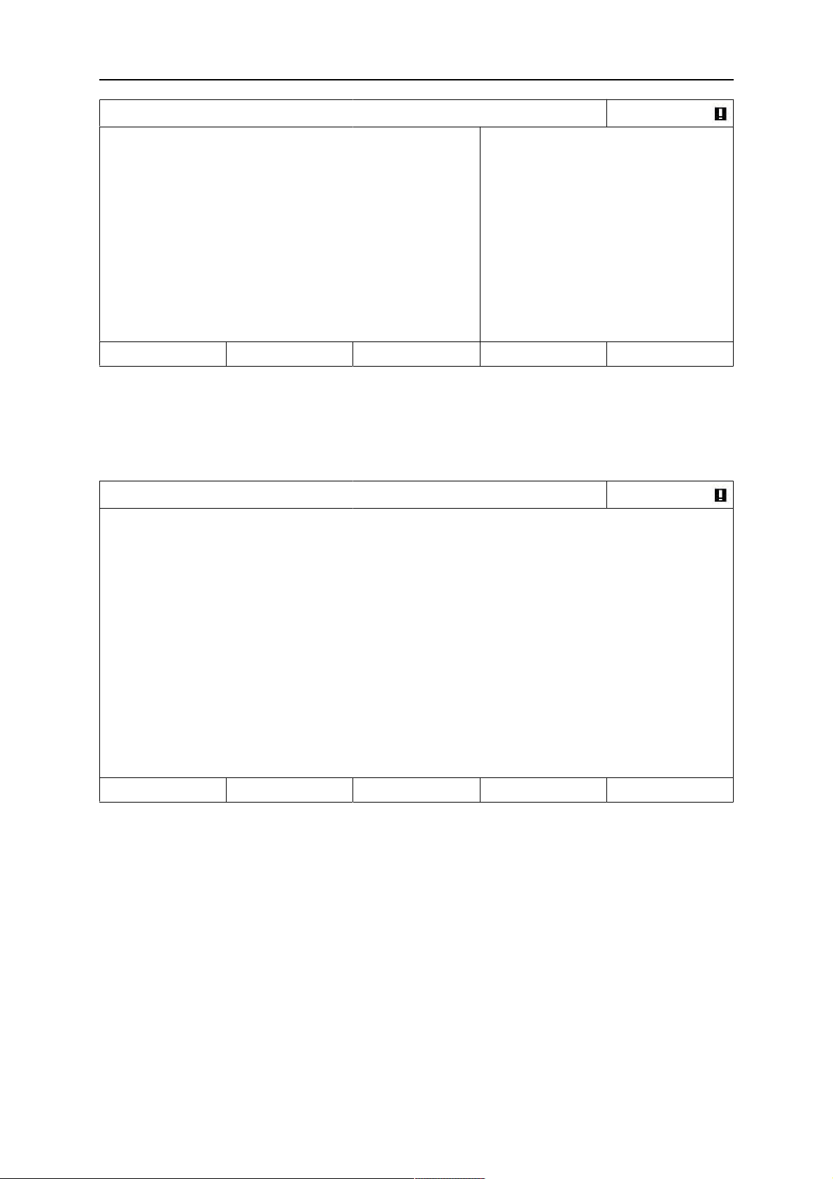
SAW: CW
NONE DIR: SQUARE NONE SET VALUES 2ND FUNCT
• 300 cm/min - Set wire feed speed
• 20.0 Volt - Set arc voltage
• 30 cm/min - Set travel speed
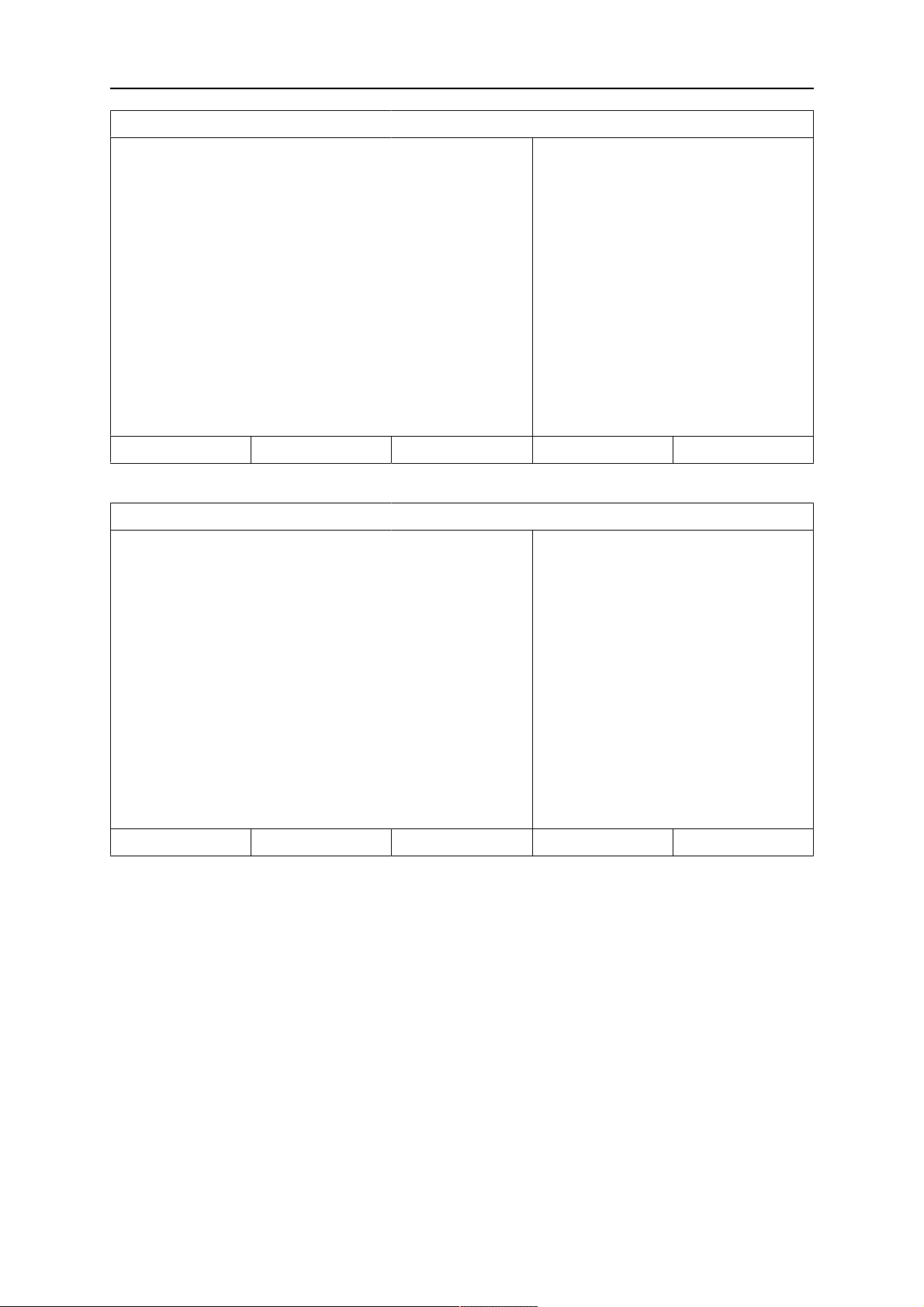
2.1.5 Weld data memory menu
MAIN MENU » MEMORY
In the WELD DATA MEMORY menu you can store, recall, delete and copy various set weld
data. The weld data sets can be stored in 255 different memory positions.
WELD DATA MEMORY
1 (SAW)
7 (GMAW)
STORE 2ND FUNCT QUIT
For further information, see section "MEMORY MANAGEMENT".
2.1.6 Fast mode menu
MAIN MENU » FAST MODE
0460 949 474
- 15 -
© ESAB AB 2021

2 MENUS
In the FAST MODE menu, you can link soft keys to weld data memory positions. These
settings are carried out in the CONFIGURATION menu. The number of the selected memory
position is displayed in the top right corner.
16
WELD DATA 1 WELD DATA 2 WELD DATA 3 WELD DATA 4 2ND FUNCT
For further information, see section "Fast mode soft keys".
0460 949 474
- 16 -
© ESAB AB 2021

3 SUBMERGED ARC WELDING
3 SUBMERGED ARC WELDING
MAIN MENU » PROCESS
During Submerged Arc Welding (SAW), an arc melts a continuously supplied wire. The weld
pool is protected by flux.
Aristo® 1000: When the SAW process is selected, choose METHOD with the positioning
knob and press ENTER. Choose AC or DC.
SAW
PROCESS
METHOD
REGULATION TYPE
WIRE TYPE
WIRE DIMENSION
SAW
AC
CC
Fe SOLID
0.8 mm
CONFIGURATION►
TOOLS►
SET MEASURE MEMORY FAST MODE
Aristo® 1000: When the SAW process is selected, you can choose between three control
methods by marking REGULATION TYPE using the positioning knob and pressing ENTER.
Choose between constant welding current CA or constant wire feed CW or constant current
CC.
LAF/TAF: When the SAW process is selected, you can choose between three control
methods by marking REGULATION TYPE using the positioning knob and pressing ENTER.
Choose between constant welding current CA or constant wire feed CW.
See explanations in "CA, constant amperage", "CW, constant wire feed" and "CC, constant
current".
If ICE wire feed is selected, see "ICE wire feed", page53, only regulation type CW can be
selected.
3.1 Settings for submerged arc welding
Settings Setting range In steps of Value after
resetting
Arc voltage
For Aristo® 1000 14 -50 V 0.1 V (1V) 30 V
For LAF/TAF 8 - 60 V 0.1 V (1V) 30 V
Welding current1)(CA)
Wire feed speed1)(CW)
Constant current
ICE wire feed speed
ICE wire start delay
Travel speed * 0 - 200 cm/min 1 cm/min 30 cm/min
Welding direction ▲-■ - ■
AC frequency
1)
0 - 3200 A 1 A 400 A
0 - 2500 cm/min 1 cm/min 100 cm/min
1) 3)
(CC)
1)
1)
3)
0 - 3200 A 1 A 500 A
0 - 200% 1% 100%
0 - 99,0 s 0,1 s 2,5 s
10 - 100 Hz 1 50 Hz
0460 949 474
- 17 -
© ESAB AB 2021

3 SUBMERGED ARC WELDING
Settings Setting range In steps of Value after
resetting
AC balance
AC offset
3)
Start data
3)
2)
25 - 75% 1 50%
-300-+ A/-10 +10V 1 A / 0.1 V 0
Flux pre-flow 0 - 99.0 s 0.1 s 0 s
Start adjust Min = 50% 1% 100%
Start type Direct orScratch - Direct
Wire creep start Auto orSet speed - Auto
Wire creep start speed 0 - 1000 cm/min 1 cm/min 20 cm/min
Start phases OFF orON - OFF
Open-circuit voltage OFF orON - OFF
Maximum open-circuit voltage 5 - 60 V 0.1 V 50 V
Stop data
2)
Flux post-flow 0 - 99.0 s 0.1 s 0 s
Crater filling OFF orON - OFF
Crater filling time 0 - 10 s 0.01 s 0.0 s
Burnback time 0- 10 s 0.01 s 0.65 s
Stop phases OFF orON - OFF
Control parameters
Dynamics Auto orSet values - Auto
Inductance Auto orSet values - Auto
Setting limits - - -
Measure limits - - -
1)
The setting range is dependent on the product used.
2)
The menu shows the settings that belong to the selected regulation type.
3)
Applies only to Aristo®1000 power sources
0460 949 474
- 18 -
© ESAB AB 2021

4 GAS METAL ARC WELDING
4 GAS METAL ARC WELDING
The process is available for certain machine types.
MAIN MENU » PROCESS
During Gas Metal Arc Welding (GMAW), an arc melts a continuously supplied wire. The weld
pool is protected by shielding gas.
When the Gas Metal Arc Welding GMAW process is selected, you can choose between two
control methods by marking REGULATION TYPE using the positioning knob and pressing
ENTER. Choose between constant amperage CA or constant wire feed CW, see explanation
in "CA, constant amperage" and "CW, constant wire feed".
GMAW
PROCESS
REGULATION TYPE
WIRE TYPE
WIRE DIMENSION
CONFIGURATION►
TOOLS►
QUIT
CA
CW
4.1 Settings for gas metal arc welding
Settings Setting range In steps of Value after
resetting
Arc voltage * 14 -50 V 0.1 V (1V) 30 V
Welding current *(CA) 0 - 3200 A 1 A 500 A
Wire feed speed *(CW) 0 - 2500 cm/min 1 cm/min 100 cm/min
GMAW
CA
Fe SOLID
0.8 mm
Travel speed * 0 - 200 cm/min 1 cm/min 30 cm/min
Welding direction ▲-■ - ■
Start data
2)
Gas pre/flow 0 - 99.0 s 0.1 s 0.2 s
Start adjust Min = 50% 1% 100%
Start type Direct orScratch - Direct
Wire creep start Auto orSet speed - Auto
Wire creep start speed 0 - 1000 cm/min 1 cm/min 20 cm/min
Start phases OFF orON - OFF
Open-circuit voltage OFF orON - OFF
Maximum open-circuit voltage 5 - 60 V 0.1 V 50 V
Stop data
Gas post-flow 0 - 99.0 s 0.1 s 0.2 s
Crater filling OFF orON - OFF
0460 949 474
- 19 -
© ESAB AB 2021

4 GAS METAL ARC WELDING
Settings Setting range In steps of Value after
resetting
Crater filling time 0 - 10 s 0.01 s 0.0 s
Burnback time 0- 10 s 0.01 s 0.20 s
Stop phases OFF orON - OFF
Dynamic regulation Auto orSet values - Auto
Setting limits - - -
Measure limits - - -
*) The setting range is dependent on the product used.
0460 949 474
- 20 -
© ESAB AB 2021

5 ELECTRO SLAG WELDING
5 ELECTRO SLAG WELDING
The process is available for LAF power sources.
MAIN MENU » PROCESS
Electro slag welding (ESW) is a single pass welding process.
ESW
PROCESS
METHOD
REGULATION TYPE
WIRE TYPE
WIRE DIMENSION
30×0,5 mm
CONFIGURATION►
TOOLS►
SET MEASURE MEMORY FAST MODE
5.1 Settings for electro slag welding
Settings Setting range In steps of Value after
resetting
Arc voltage
1)
Welding current1)(CA)
Wire feed speed1)(CW)
Travel speed * 0 - 200 cm/min 1 cm/min 30 cm/min
8 - 60 V 0.1 V (1V) 24 V
0 - 3200 A 1 A 400 A
0 - 2500 cm/min 1 cm/min 300 cm/min
ESW
AC
CA
SS Strip
Welding direction ▲-■ - ■
Start data
2)
Flux pre-flow 0 - 99.0 s 0.1 s 0 s
Start adjust Min = 100% 1% 100%
Start type Direct orScratch - Direct
Wire creep start Auto orSet speed - Auto
Wire creep start speed 0 - 1000 cm/min 1 cm/min 2 cm/min
Start phases OFF orON - OFF
Open-circuit voltage OFF orON - OFF
Maximum open-circuit voltage 5 - 60 V 0.1 V 50 V
Stop data
2)
Flux post-flow 0 - 99.0 s 0.1 s 0 s
Crater filling OFF orON - OFF
Crater filling time 0 - 10 s 0.01 s 0.0 s
Burnback time 0- 10 s 0.01 s 1.50 s
Stop phases OFF orON - OFF
Control parameters
Dynamics Auto orSet values - Auto
0460 949 474
- 21 -
© ESAB AB 2021

5 ELECTRO SLAG WELDING
Settings Setting range In steps of Value after
resetting
Inductance Auto orSet values - Auto
Setting limits - - -
Measure limits - - -
1)
The setting range is dependent on the product used.
2)
The menu shows the settings that belong to the selected regulation type.
0460 949 474
- 22 -
© ESAB AB 2021

6 GOUGING
6 GOUGING
Availability depending on connected equipment.
MAIN MENU » PROCESS
With arc air gouging, a special electrode comprising a carbon rod with a copper casing is
used.
An arc is formed between the carbon rod and the work piece, which melts the material. Air is
supplied so that the melted material is blown away.
When the GOUGING process is selected, you can choose between two control methods by
marking REGULATION TYPE using the positioning knob and pressing ENTER. Choose
between constant amperage CA or constant wire feed CW, see explanation in "CA, constant
amperage", page25 and "CW, constant wire feed", page25.
GOUGING
PROCESS
METHOD
REGULATION TYPE
WIRE DIMENSION
GOUGING MODE
GOUGING
DC
CW
8.0 mm
N7500
CONFIGURATION►
TOOLS►
QUIT
CA
CW
Select GOUGING MODE with the positioning knob. Press ENTER. For Aristo® 1000, select
AUTO or N7500. For LAF and TAF select AUTO or MANUAL.
GOUGING
PROCESS
METHOD
GOUGING
DC
REGULATION TYPE
WIRE DIMENSION
GOUGING MODE
CONFIGURATION►
TOOLS►
N7500
0460 949 474
AUTO
- 23 -
CW
8.0 mm
N7500
QUIT
© ESAB AB 2021

6 GOUGING
6.1 Settings for gouging
Settings Setting range In steps of Value after
resetting
Arc voltage * 14 -50 V 0.1 V (1V) 30 V
Welding current *(CA) 0 - 3200 A 1 A 500 A
Wire feed speed *(CW) 0 - 2500 cm/min 1 cm/min 100 cm/min
Travl speed * 0 - 200 cm/min 1 cm/min 30 cm/min
Welding direction ▲-■ - ■
Start data
Air pre-flow 0 - 99.0 s 0.1 s 0 s
Start adjust Min = 50% 1% 100%
Start type Direct orScratch - Direct
Wire creep start Auto orSet speed - Auto
Wire creep start speed 0 - 1000 cm/min 1 cm/min 20 cm/min
Start phases OFF orON - OFF
Open-circuit voltage OFF orON - OFF
Maximum open-circuit voltage 5 - 60 V 0.1 V 50 V
Stop data
Air post-flow 0 - 99.0 s 0.1 s 0 s
Crater filling OFF orON - OFF
Crater filling time 0 - 10 s 0.01 s 0.0 s
Burnback time 0- 10 s 0.01 s 1.50 s
Stop phases OFF orON - OFF
Dynamic regulation Auto orSet values - Auto
Setting limits - - -
Measure limits - - -
*) The setting range is dependent on the product used.
0460 949 474
- 24 -
© ESAB AB 2021

7 FUNCTION EXPLANATIONS
7 FUNCTION EXPLANATIONS
7.1 CA, constant amperage
The wire feed is controlled by the power source so that a constant amperage can be
achieved.
• Constant current value can be selected in the main menu.
7.2 CW, constant wire feed
The welding current is a result of the selected wire feed speed.
• Constant wire feed can be selected in the main menu.
7.3 CC, constant current
(applies only to Aristo® 1000 power source)
The voltage is varied so that a constant welding current can be achieved.
• Constant current value can be selected in the main menu.
A higher wire speed gives a higher welding current.
7.4 Wire / electrode dimension
Selected dimensions have a great impact on the start procedure and crater filling. When
welding with other wire dimensions other than those found in the table, select one that has a
dimension close to one in the list.
• Wire / electrode dimension can be selected in the main menu. The available wire
material and dimension are affected by the combination of power source and welding
head.
7.5 Arc voltage
Higher arc voltage increases the arc length and produces a hotter, wider weld pool.
• The arc voltage is set in the measurement display, weld data setting menu, or fast
mode menu.
7.6 Wire feed speed
This sets the required feed speed of the filler wire in cm/minute. A higher wire speed gives a
higher welding current.
• The wire feed speed is set in the measurement display, weld data setting menu, or fast
mode menu.
7.7 ICE wire feed speed
Cold wire feed speed is used to set a feed speed (cm/min or inch/min) for the cold wire.
• The cold wire feed speed is set in the measurement display, weld data setting menu, or
fast mode menu.
0460 949 474
- 25 -
© ESAB AB 2021

7 FUNCTION EXPLANATIONS
7.8 ICE wire start delay
Cold wire start delay is used to indicate how long (s) after welding start cold wire feed can
start.
• Cold wire start delay is set in the weld data setting menu.
7.9 Travel speed
Travel speed indicates the required speed (cm/min) at which a column and boom or trolley is
to move.
• The travel speed is set in the measurement display, weld data setting menu, or fast
mode menu.
7.10 Welding direction
Travel motion in the direction that the symbol indicates.
• Welding direction is selected in the weld data setting menu.
7.11 AC frequency
(applies only to Aristo® 1000 power source)
AC frequency refers to the number of oscillations per second through the zero level.
• AC frequency is selected in the weld data setting menu.
7.12 AC balance
(applies only to Aristo® 1000 power source)
AC balance is the relationship between positive (+) and negative (-) pulses. The value that is
set indicates the percentage size of the period that is the positive section.
• AC balance is selected in the weld data setting menu.
7.13 AC offset
(applies only to Aristo® 1000 power source)
With AC offset the AC level is offset positively or negatively in relation to the zero level.
• AC offset is selected in the weld data setting menu.
7.14 Flux pre-flow (SAW)
This controls the time during which flux flows before the arc is struck.
• Flux pre-flow is set in the weld data setting menu under start data.
7.15 Gas pre-flow (GMAW)
This controls the time during which shielding gas flows before the arc is struck.
• Gas pre-flow is set in the weld data setting menu under start data.
7.16 Start adjust
This is used to adjust the starting current values. If the equipment starts with lower current
values, compared with equipment's factory values, they can be adjusted here.
0460 949 474
- 26 -
© ESAB AB 2021

7 FUNCTION EXPLANATIONS
• Start adjust is set in the weld data setting menu under start data.
7.17 Air pre-flow (Gouging)
This controls the time during which air flows before the arc is struck.
• Air pre-flow is set in the weld data setting menu under start data.
7.18 Start type
There are two options for start type:
• Direct start, means that the travel speed starts when the arc is struck.
• Scratch start, means that the travel speed starts at the same time as wire feed.
• Start type is selected in the weld data setting menu under start data.
7.19 Wire creep start
Wire creep start is used to set the desired creep speed on the electrode motor upon start-up.
If, for example, 50 is set in the menu a creep speed of 50 cm/min is obtained.
Preset value ”AUTO” gives a creep speed calculated from the set values.
• Wire creep speed is set in the weld data setting menu under start data.
7.20 Start phases
When welding special wire or material, it may be necessary to create your own start
sequence. The start sequence can affect the appearance of the weld pool.
The following can be set for Start phase1
ON
• Time s
Time for welding in phase 1.
• Arc voltage %
In percent of set voltage
• Wire feed %
In percent of set wire feed
• Welding current %
In percent of set welding current
• Travel speed %
In percent of set travel speed
• Start phases are set in the weld data setting menu under start data.
The following can be set for Start phase2
ON
• Time s
Time for welding in phase 2.
• Arc voltage %
In percent of set voltage
• Wire feed %
In percent of set wire feed
• Welding current %
In percent of set welding current
• Travel speed %
In percent of set travel speed
7.21 Max Open Circuit Voltage (OCV)
ON means that OCV can be set.
OFF means that OCV is set to the set value for welding voltage.
• OCV is set in the weld data setting menu under start data.
7.22 Flux post-flow (SAW)
This controls the time during which flux flows after the arc is extinguished.
• Flux post-flow is set in the weld data setting menu under stop data.
0460 949 474
- 27 -
© ESAB AB 2021

7 FUNCTION EXPLANATIONS
7.23 Gas post-flow (GMAW)
This controls the time during which shielding gas flows after the arc is extinguished.
• Gas post-flow is set in the weld data setting menu under stop data.
7.24 Air post-flow (Gouging)
This controls the time during which air flows after the arc is extinguished.
• Air post-flow is set in the weld data setting menu under stop data.
7.25 Crater filling
Crater filling makes a controlled reduction in the heat and size of the weld pool possible
when completing the weld. This makes it easier to avoid pores, thermal cracking and crater
formation in the weld joint.
• Crate filling is set in the weld data setting menu under stop data.
7.26 Burnback time
Burnback time is a delay between the time when the wire starts to brake until the time when
the power source switches off the arc voltage. Too short burnback time results in a long wire
stickout after completion of welding, with a risk of the wire being caught in the solidifying weld
pool. Too long burnback time results in a shorter stickout, with increased risk of the arc
striking back to the contact tip.
• Burnback time is set in the weld data setting menu under stop data.
7.27 Stop phases
Stop phases are mainly used for setting crater filling.
The following can be set for Stop phase1
ON
• Time s
Time for welding in phase 1.
• Arc voltage %
In percent of set voltage
• Wire feed %
In percent of set wire feed
• Welding current %
In percent of set welding current
• Travel speed %
In percent of set travel speed
The following can be set for Stop phase2
ON
• Time s
Time for welding in phase 2.
• Arc voltage %
In percent of set voltage
• Wire feed %
In percent of set wire feed
• Welding current %
In percent of set welding current
• Travel speed %
In percent of set travel speed
• Stop phases are set in the weld data setting menu under stop data.
7.28 Dynamic regulation
The dynamic regulation function is developed for multiple electrode welding and alters the
characteristics of the power source. The characteristics of the power source are calculated
from the set wire data.
• Dynamic regulation is selected in the weld data setting menu.
0460 949 474
- 28 -
© ESAB AB 2021

7 FUNCTION EXPLANATIONS
7.29 Control parameters
In some applications the function Control parameters is displayed instead of Dynamic
control. There are two settings to make under Control parameters:
• DYNAMICS - Affects the dynamic characteristics
• INDUCTANCE - Higher values give a wider weld pool and less spatter. Lower values
produce a stable, concentrated arc and a harsher sound.
• Control parameters are selected in the weld data setting menu.
7.30 Setting limits
For information about setting limits see section "Setting limit editor".
7.31 Measure limits
For information about measurement parameters see section "Measure limits editor".
7.32 PEK control unit as separate motor control
PEK as motor control without a power source is used when you want to have a travel control
and possibility to give a start signal to an external power source. Remote is also active via
ATAS I/O so you can control a roller bed with relay out for the start and an analogue
reference for speed.
Activate motor control
To activate the motor control function set PRODUCT CODE to MOTOR CONTROL. The
supervision by the power source is now disabled.
MACHINE CONFIGURATION
PRODUCT CODE
WIRE FEED AXIS►
TRAVEL AXIS►
TANDEM►
PARALLEL POWERSOURCES►
ICE WIRE FEED►
NODE ID SETTINGS►
SYSTEM INFORMATION►
A6TF F1
MTW600
Motor control
QUIT
OFF
0460 949 474
FREE 2 AXIS
FREE 3 AXIS
N7500I
Motor control
- 29 -
© ESAB AB 2021
7 FUNCTION EXPLANATIONS
Travel axis and wire axis
Set travel axis and wire gearing by performing the same procedure as for product code
external axis.
Setting menu
Here you can set travel speed and direction, start data and limits can be used for travel
speed.
SAW WELD DATA SETTING
TRAVEL SPEED
30 cm/min
DIRECTION
START DATA►
SETTING LIMITS►
MEASURE LIMITS►
MEASURE QUIT
Start data menu
Flux/Gas pre-flow is active if the chosen start type is scratch. Start signal (relay output 2) will
be generated, and when pre-flow time has elapsed travel will start. When start type direct is
chosen, pre-flow has no function.
SAW START DATA
FLUX PREFLOW
START TYPE
0.0 s
DIRECT
MEASURE QUIT
Scratch start will start a travel and generate start signal out at the same time when the start
button is pressed. Pre-flow has no function.
When starting relay output 2, a direct start will be generated, but travel will not start until
digital input for current flow is active. So if no input on I/O ATAS for current flow, use scratch
start instead.
■
SAW START DATA
FLUX PREFLOW
START TYPE
0.0 s
SCRATCH
MEASURE QUIT
Measure menu
In the measure menu, you can see measure values for travel speed and jog wire speed. The
wire motor is not started when you press the start button on the PEK control unit, but you can
use that motor for other work. In the setting menu, you can also set travel speed.
0460 949 474
- 30 -
© ESAB AB 2021

7 FUNCTION EXPLANATIONS
SAW: CW FE SOLID ■
NONE DIR. SQUARE NONE SET VALUES 2ND FUNCT
Remote and external axis
Remote via ATAS I/O and external axis for controlling a roller bed can also be used together
with motor control.
SAW_DC: DC+:EXT ▲
REMOTE IO DIR. SQUARE EXT. AXIS SET VALUES 2ND FUNCT
Machine configuration
With product code motor control you can set gearing as with free three axis on wire feed,
travel and external axis.
MACHINE CONFIGURATION
PRODUCT CODE
Motor control
WIRE FEED AXIS►
TRAVEL AXIS►
EXTERNAL AXIS►
QUIT
ATAS I/O
Digital inputs:
1. Start weld, X22.1.
2. Stop, X22.2.
3. Jog travel square direction, X22.3.
4. Jog travel triangle direction, X22.4.
5. Wire up direction, wire motor is not started when weld start is pressed, X23.1.
6. Wire down direction, wire motor is not started when weld start is pressed, X23.2.
7. High speed jog, X23.3.
8. Limit switch square, X23.4.
9. Limit switch triangle, X24.1.
10. Current flow, will start travel when direct start is used, when falling it will stop weld,
X24.2.
0460 949 474
- 31 -
© ESAB AB 2021

7 FUNCTION EXPLANATIONS
11. External axle, roller bed control, X24.3.
12. Not used, X24.4.
13. Not used, X25.1.
14. Not used, X25.2.
15. Error from external equipment, X25.3.
16. Not used, X25.4.
Digital relay outputs:
1. Roller bed active, X26.2.
2. Boom active, X26.4.
3. Not used, X26.6.
4. Not used, X26.8.
5. Start square direction when external axis is active, X27.2.
6. Start triangle direction when external axis is active, X27.4.
7. Roller bed active, X27.6.
8. Error active that prevent start, X27.8.
Analogue out
1. Speed reference signal in external axis method, 0-10V. X18.
Motor card
Start signal to external equipment’s as the power source is located on connector X1.15-16.
0460 949 474
- 32 -
© ESAB AB 2021
8 MEMORY MANAGEMENT
8 MEMORY MANAGEMENT
8.1 Control panel working method
The control panel can be said to comprise two units: working memory and weld data
memory.
Store
Working Memory
In the working memory, a complete set of weld data settings is created that can be stored in
the weld data memory.
During welding, it is always the content of the working memory that controls the process. It is
therefore also possible to recall a weld data set from the weld data memory to the working
memory.
Note that the working memory always contains the most recently set weld data settings.
They can be recalled from the weld data memory or individually altered settings. In other
words, the working memory is never empty or “zeroed”.
MAIN MENU » MEMORY » WELD DATA MEMORY
WELD DATA MEMORY
STORE 2ND FUNCT QUIT
Recall
Welding data memory
It is possible to store up to 255 sets of weld data in the control panel. Each set is given a
number from 1 to 255.
You can also delete, copy, change and name data sets and recall a set of weld data to the
working memory.
8.2 Store
If the weld data memory is empty, the following screen appears in the display.
Storing a set of weld data. This will be given memory position 5. Press STORE.
Position 1 is displayed. Turn one of the settings knobs until you reach position 5. Press
STORE.
WELD DATA MEMORY
STORE 2ND FUNCT QUIT
The following screen appears in the display.
The weld data set is now stored as number 5.
0460 949 474
- 33 -
© ESAB AB 2021
8 MEMORY MANAGEMENT
WELD DATA MEMORY
5 - (SAW)
SAW: CA: FE SOLID: 3.0 mm
30.0 V: 450 A: 50 cm/min
STORE RECALL DELETE 2ND FUNCT QUIT
Parts of the content of weld data set number 5 are presented at the bottom of the display.
If a data set is already stored in the selected location, you will be asked if you want to
overwrite that set or not, YES or NO.
WELD DATA MEMORY
5 - (SAW)
SAW: CA: FE SOLID: 3.0 mm
30.0 V: 450 A: 50 cm/min
OVERWRITE DATA SET5 IN MEMORY?
Return to the memory menu using NO.
8.3 Recall
We are going to recall a stored data set:
Mark the row using the positioning knob. Press RECALL.
WELD DATA MEMORY
5 - (SAW)
NO YES
SAW: CA: FE SOLID: 3.0 mm
30.0 V: 450 A: 50 cm/min
STORE RECALL DELETE 2ND FUNCT QUIT
Press YES to confirm that you want to recall data set number 5.
0460 949 474
- 34 -
© ESAB AB 2021
8 MEMORY MANAGEMENT
WELD DATA MEMORY
5 - (SAW)
SAW: CA: FE SOLID: 3.0 mm
30.0 V: 450 A: 50 cm/min
NO YES
RECALL DATA SET 5 FROM MEMORY?
The icon in upper right corner of the measurement display shows which memory position
number has been recalled.
SAW: FE SOLID 5
NONE NONE NONE NONE 2ND FUNCT
8.4 Delete
It is possible to delete one or more data sets in the memory menu.
Deleting a data set. Select the data set. Press DELETE.
WELD DATA MEMORY
5 - (SAW)
SAW: CA: FE SOLID: 3.0 mm
30.0 V: 450 A: 50 cm/min
STORE RECALL DELETE 2ND FUNCT QUIT
Press YES to confirm that you want to delete.
0460 949 474
- 35 -
© ESAB AB 2021

8 MEMORY MANAGEMENT
WELD DATA MEMORY
5 - (SAW)
SAW: CA: FE SOLID: 3.0 mm
30.0 V: 450 A: 50 cm/min
NO YES
DELETE WELD DATA NR. 5?
8.5 Copy
To copy the content of a weld data set to a new memory position, proceed as follows:
Press 2ND FUNCT.
WELD DATA MEMORY
5 - (SAW)
SAW: CA: FE SOLID: 3.0 mm
30.0 V: 450 A: 50 cm/min
STORE RECALL DELETE 2ND FUNCT QUIT
Select the memory position you want to copy and press COPY.
WELD DATA MEMORY
5 - (SAW)
SAW: CA: FE SOLID: 3.0 mm
30.0 V: 450 A: 50 cm/min
COPY RENAME EDIT 2ND FUNCT QUIT
We are now going to copy the content of memory position 5 to position 50.
Select memory position 1 and scroll through using one of the settings knobs to the selected
memory position; in this case, position 50. Press YES.
0460 949 474
- 36 -
© ESAB AB 2021
8 MEMORY MANAGEMENT
WELD DATA MEMORY
1 -
5 - (SAW)
COPY
DATA SET 5 TO POSITION: 50
NO YES
Weld data number 5 has now been copied to memory position 50.
8.6 Name
To give a stored weld data set its own name, proceed as follows:
Press 2ND FUNCT. Select the memory position you want to rename and press RENAME.
WELD DATA MEMORY
5 - (SAW)
50 -
SAW: CA: FE SOLID: 3.0 mm
30.0 V: 450 A: 50 cm/min
COPY RENAME EDIT 2ND FUNCT QUIT
Here you have access to a keyboard that is used as follows:
• Position the cursor on the desired keyboard character using the arrows and the
positioning knob. Press DONE. Enter a complete text string with a maximum of 40
characters in this way.
• Press DONE to store. The alternative you have named can now be seen in the list.
KEYBOARD
A B C D E F G H
I J K L M N O P
Q R S T U V W X Y Z
0 1 2 3 4 5 6 7 8 9
SPACE CAPS
0 (MAX 40)
DELETE SYMBOL DONE
8.7 Edit
To edit the content of a weld data set, proceed as follows:
Press 2ND FUNCT. Select the memory position you want to edit and then press EDIT.
0460 949 474
- 37 -
© ESAB AB 2021

8 MEMORY MANAGEMENT
WELD DATA MEMORY
5 - (SAW)
SAW: CA: FE SOLID: 3.0 mm
30.0 V: 450 A: 50 cm/min
STORE RECALL DELETE 2ND FUNCT QUIT
Part of the main menu is displayed and the menu shows the symbol which means that
you are in an editing mode.
Press SET and make the relevant changes.
SAW
REGULATION TYPE
WIRE TYPE
SS FLUX CORED
WIRE DIMENSION
SET QUIT
The following menu appears:
In this example we change the welding current from 400 A to 500 A.
Select the welding current and scroll through to 500 using one of the settings knobs.
Press QUIT twice.
SAW WELD DATA SETTING
VOLTAGE
CURRENT
TRAVEL SPEED
DIRECTION
CA
2.0 mm
20.0 V
500 A
0 cm/min
■
START DATA►
STOP DATA►
DYNAMIC REGULATION
SETTING LIMIT►
MEASURE LIMITS►
The setting for weld data number 5 has now been edited and stored.
0460 949 474
- 38 -
AUTO
QUIT
© ESAB AB 2021
9 CONFIGURATION MENU
9 CONFIGURATION MENU
MAIN MENU » CONFIGURATION
This menu contains the following sub-menus:
• Language, see section "Choice of language".
• Code lock, see section "Code lock".
• General configuration, see section "General configuration".
• Machine configuration, see section "Machine configuration".
• Cable lengths, see section "Cable lengths (applies only to LAF and TAF power
sources)".
• Maintenance, see section "Maintenance".
• Measure–values filter factor, see section "Measure–values filter factor".
9.1 Code lock
MAIN MENU » CONFIGURATION » CODE LOCK
When the lock function is activated and you are in the measure screen or fast mode menu, a
password (lock code) is required to exit from these menus.
Code lock is activated in the configuration menu.
CODE LOCK
LOCK STATUS
SET / CHANGE LOCK CODE
QUIT
OFF
9.1.1 Lock code status
In lock code status, you can activate/deactivate the lock function without deleting the existing
lock code in the event you deactivate the function. If no lock code is stored and you try to
activate the code lock, the keyboard is displayed for entering a new lock code.
KEYBOARD
A B C D E F G H
I J K L M N O P
Q R S T U V W X Y Z
0 1 2 3 4 5 6 7 8 9
SPACE CAPS
0 (MAX 16)
DELETE SYMBOL DONE
To exit lock status.
When you are in the measure screen or the fast mode menu and the code lock is
deactivated, you can exit these menus without restrictions by pressing QUIT or MENU in
order to go to the main menu.
0460 949 474
- 39 -
© ESAB AB 2021

9 CONFIGURATION MENU
If it is activated and you try to exit, the following screen appears in order to warn the user
about the lock protection.
PRESS ENTER FOR
LOCK CODE...
Here you can select QUIT to undo and return to the previous menu, or proceed by pressing
ENTER to enter the lock code.
You will then move to the menu with the keyboard, where you can enter the code. Press
ENTER after each character, and confirm the code by pressing ENTER again.
The following text box appears:
UNIT UNLOCKED!
If the code is not correct, an error message is displayed that offers the option of trying again
or returning to the original menu, i.e. the measure screen or the fast mode menu.
If the code is correct, all blocks to other menus will be removed, although the code lock
remains activated. This means that you can leave the measure screen and the fast mode
menu temporarily, yet still retain the lock status when you return to these menus.
9.1.2 Specify/edit lock code
In specify/edit lock code, you can edit an existing lock code or enter a new one. A lock code
can comprise a maximum of 16 optional letters or figures.
9.2 General configuration
MAIN MENU » CONFIGURATION » GENERAL CONFIGURATION
In this menu you can set:
• Fast mode soft keys, see section "Fast mode soft keys".
• Quality data log to file, see section "Quality data log to file".
• Setting soft keys, see section "Soft key configuration".
• Automatic weld data storage, see section "Auto save mode".
• Unit of length, see "Unit of measurements".
9.2.1 Fast mode soft keys
The soft keys WELD DATA 1 up to and including WELD DATA 4 are displayed in the fast
mode menu.
SAW: CA 16
WELD DATA 1 WELD DATA 2 WELD DATA 3 WELD DATA 4 2ND FUNCT
These are configured as follows:
Position the cursor on the row for SOFT KEY NUMBER.
0460 949 474
- 40 -
© ESAB AB 2021

9 CONFIGURATION MENU
FAST MODE SOFT KEYS
SOFT KEY NUMBER
ASSOCIATED WELD DATA
SAW: CA: FE SOLID: 0.8 mm
20.0 V: 500 A: 0 cm/min
STORE DELETE QUIT
The keys are numbered 1-4 from left to right. Select the desired key by giving its number
using the setting knobs.
Then scroll to the next row ASSOCIATED WELD DATA. Here you can browse through the
weld data sets that are stored in the weld data memory. Selected the desired weld data
number using the setting knobs. Press STORE to save. To delete the stored set, press
DELETE.
9.2.2 Quality data log to file
Activate QUALITY DATA LOG TO FILE menu by selecting ON.
1
5
GENERAL CONFIGURATION
FAST MODE SOFT BUTTONS
QUALITY DATA LOG TO FILE
SOFT KEYS SETUP►
AUTO SAVE MODE
UNIT OF LENGTH
METRIC
QUIT
Read more about settings for the quality function in section "Quality functions".
9.2.3 Soft key configuration
For Submerged Arc Welding (SAW) and for Gas Metal Arc Welding (GMAW) welding, the
user has the possibility of setting the function of these keys by selecting from a list of set
options. There are eight soft keys that can be allocated a function.
It is possible to choose between the following options:
• None
• Gas / Flux
• Set values
Set reference values are displayed instead of the measured values in the
measurements menu.
• Relay 2
Sets relay output no.2 on the motor circuit board, which can be used for any function by
the customer.
• Direction
• Remote I/O
Used when you want to control PEK and a welding power source via an external I/O
unit.
1
ON
OFF
0460 949 474
- 41 -
© ESAB AB 2021
9 CONFIGURATION MENU
• External axis
To be activated when there is an external I/O unit for controlling a roller bed, for
example.
• Tandem
Used when welding with two welding heads.
• Cold wire (ICE)
Used when a non-live wire is fed into the weld pool and the cold wire speed is to be
shown in the display.
• Auto step
Used in the step function
○ Auto step Off: Setting during preparation of the object before welding
○ Auto step On: Setting after preparation is finished when welding should be
executed
• Force step
Used in the step function to manually force one auto step during welding
• Restart step
When welding is stopped with 100mm left to the start of the next step. Press restart
step and the next step is after 100mm, not after Xmm. Then press the welding start key.
• Stop zero
Used to stop automatically at the started rotation position.
In the display screen there are two columns; one for SOFT KEYS and one for FUNCTION.
SOFT KEYS SETUP
SOFT KEYS FUNCTION
S1
S2
S3
S4
S1 2ND FUNCT
S2 2ND FUNCT
S3 2ND FUNCT
S4 2ND FUNCT
NONE
NONE
NONE
NONE
NONE
NONE
NONE
NONE
QUIT
When you allocate functions to these keys, they are numbered from the left as follows:
S1 S2 S3 S4 2ND FUNCT
S1 2ND FUNCT S2 2ND FUNCT S3 2ND FUNCT S4 SND FUNCT 2ND FUNCT
To allocate a new function to a soft key, proceed as follows:
Position the cursor on the row with the soft key number you wish to use and press ENTER. A
pop-up menu shows the function selections. Select using the positioning knob and press
ENTER.
0460 949 474
- 42 -
© ESAB AB 2021

9 CONFIGURATION MENU
SOFT KEY SETUP
SOFT KEYS FUNCTION
S1
S2
S3
S4
S1 2ND FUNCT
S2 2ND FUNCT
S3 2ND FUNCT
S4 2ND FUNCT
NONE
NONE
NONE
NONE
NONE
NONE
NONE
NONE
QUIT
NONE
GAS / FLUX
SET VALUES
RELAY 1
DIRECTION
REMOTE IO
EXT. AXIS
AUTO STEP
FORCE STEP
RESTART STEP
STOP ZERO
You can allocate new functions to the other keys in the same way, by pairing a key number in
the left-hand column with a function in the right-hand column.
9.2.4 Auto save mode
When a weld data set has been recalled from a memory position in the weld data memory
and you change the settings, the changes will be saved in the working memory at welding
stop in the last recalled memory position.
Saving weld data manually in a memory position disables the next automatic save.
The memory position in which the weld data set is stored is displayed in the top right corner
of the measure screen.
9.3 Machine configuration
MAIN MENU » CONFIGURATION » MACHINE CONFIGURATION
In this menu you can set:
• Product code, see section "Product code".
• Wire feed axis, see section "Wire feed axis".
• Cold wire feed axis, see section "Cold wire axis (ICE)".
• Travel axis, see section "Travel axis".
• External axis, see section "External axis".
0460 949 474
- 43 -
© ESAB AB 2021

9 CONFIGURATION MENU
• Tandem, see section "Tandem for LAF and TAF power sources", and "Tandem for
Aristo® 1000 power source".
• Parallel power sources, see section "Parallel power sources (applies only to Aristo
1000® power sources)".
• ICE wire feed, see section "ICE wire feed".
• Step function, see section "Step function".
• Intermittent welding, see section "Intermittent welding "
• Polarity, see section "Polarity (applies only to Aristo® 1000 power source)".
• Node ID settings, see section "Node id settings (applies only to Aristo® 1000 power
source)".
• System information, see section "System information (applies only to Aristo® 1000
power source)".
9.3.1 Product code
In the PRODUCT CODE menu it is possible to select the automatic welding machine, column
and boom, roller bed or positioner to be used.
MACHINE CONFIGURATION
PRODUCT CODE
A2TF J1
WIRE FEED AXIS►
TRAVEL AXIS►
TANDEM►
PARALLEL POWERSOURCES►
ICE WIRE FEED►
STEP FUNCTION►
OFF
OFF
INTERMITTENT WELDING
NODE ID SETTINGS►
POSITIVE
SYSTEM INFORMATION►
QUIT
When selecting product code, the correct motor type and gear ratio for the used gearbox in
the relevant product are selected automatically.
0460 949 474
- 44 -
© ESAB AB 2021

9 CONFIGURATION MENU
The following options can be selected:
• A2TFJ1
A2 tractor automatic welding machine for Submerged Arc Welding (SAW)
• A2TGJ1
A2 tractor automatic welding machine for Gas-Shielded Metal Arc Welding (GMAW)
• A6TFF1
A6 tractor automatic welding machine for Submerged Arc Welding (SAW)
• MTW600
A6 tractor automatic welding machine for Submerged Arc Welding (SAW)
• FREE 2 AXIS
Optional configuration for connecting 2 motors to the actuator board. One for wire feed
and one for travel motion.
• FREE 3 AXIS
Optional configuration for connecting external roller beds, positioners or linear axis as
well as for 2 motors to the actuator board. One for wire feed and one for travel motion.
• N7500I
Welding head for Gouging.
• Motor Control
Optional configuration to use PEK control unit for separate motor control without a
power source.
9.3.2 Wire feed axis
The wire feed motor is set automatically according to the tables below.
A2TFJ1 A2TGJ1 A6TFF1 MTW600
Motor 5035 38 RPM 5035 68 RPM VEC 4000 FHP258
Gear 1 49:1 49:1 156:1 24:1
Gear 2 1:1 1:1 1:1 1:1
Diameter feed rollers 49 mm 49 mm 49 mm 30 mm
Pulse sensor 28 ppr 28 ppr 32 ppr 28 ppr
Low manual speed 150 cm/min 150 cm/min 150 cm/min 150 cm/min
High manual speed 300 cm/min 300 cm/min 300 cm/min 300 cm/min
FREE 2 AXIS FREE 3 AXIS N7500I Motor Control
Motor VEC 4000 VEC 4000 N7500i 10000 VEC 4000
Gear 1 156:1 156:1 576:1 156:1
Gear 2 1:1 1:1 1:1 1:1
Diameter feed
rollers
49 mm 49 mm 40mm 49mm
Pulse sensor 32 ppr 32 ppr 128ppr 32ppr
Low manual
150 cm/min 150 cm/min 61cm/min 150cm/min
speed
High manual
300 cm/min 300 cm/min 150cm/min 300cm/min
speed
0460 949 474
- 45 -
© ESAB AB 2021

9 CONFIGURATION MENU
9.3.3 Cold wire axis (ICE)
FREE 2 AXIS FREE 3 AXIS
Motor VEC 4000 VEC 4000
Gear 1 156:1 156:1
Gear 2 1:1 1:1
Diameter feed rollers 49 mm 49 mm
Pulse sensor 32 ppr 32 ppr
Low manual speed 150 cm/min 150 cm/min
High manual speed 300 cm/min 300 cm/min
9.3.4 Travel axis
The travel motor is set automatically according to the tables below.
A2TFJ1 A2TGJ1 A6TFF1 MTW600
Motor 4030-350 4030-350 FHP258 FHP258
Gear 1 375:10 375:10 24:1 75:2
Gear 2 51:1 51:1 51:1 51:1
Wheel diameter 158 mm 158 mm 180 mm 158 mm
Pulse sensor 60 ppr 60 ppr 28 ppr 60 ppr
High manual speed 200 cm/min 200 cm/min 200 cm/min 200 cm/min
FREE 2 AXIS FREE 3 AXIS N7500I Motor Control
Motor VEC 4000 VEC 4000 VEC 4000 VEC 4000
Gear 1 312:1 312:1 75:2 312:1
Gear 2 1:1 1:1 51:1 1:1
Wheel diameter 65 mm 65 mm 158mm 65mm
Pulse sensor 32 ppr 32 ppr 60ppr 32ppr
High manual
200 cm/min 200 cm/min 200cm/min 200cm/min
speed
9.3.5 External axis
When connecting an external roller bed, positioner or linear axis, FREE 3 AXIS must be
selected.
When FREE 3 AXIS is selected, the motor is automatically set according to the tables below.
Roller bed Linear Positioner
Gear 1 560:1 560:1 560:1
Gear 2 111:22 111:22 111:22
Gear 3 1:1 1:1 1:1
Wheel diameter 160 mm 160 mm 160 mm
Pulse sensor 30 ppr 30 ppr 30 ppr
High manual speed 200 cm/min 200 cm/min 200 cm/min
Frequency ratio 85:50 85:50 85:50
Motor 2000 rpm 2000 rpm 2000 rpm
0460 949 474
- 46 -
© ESAB AB 2021
9 CONFIGURATION MENU
Weld diameter 1000 mm - 1000 mm
Roller diameter 1000 mm - -
When the positioner and the speed wheel are ON, the speed wheel (encoder) is at the
welding object.
When the positioner and the speed wheel are OFF, the speed wheel (encoder) is at the
motor shaft.
When the roller bed and the speed wheel are ON, the speed wheel (encoder) is at the roller
bed wheel.
When the roller bed and the speed wheel are OFF, the speed wheel (encoder) is at the motor
shaft.
9.3.6 Tandem for LAF and TAF power sources
Used when welding with two welding heads.
Position the cursor on the TANDEM row and press ENTER. Select ON, using the positioning
knob and press ENTER.
MACHINE CONFIGURATION
PRODUCT CODE
A2TF J1
WIRE FEED AXIS►
TRAVEL AXIS►
TANDEM►
└ WELDING HEAD
└ WELD HEAD OFFSET
└ WITH I/O
ON
HEAD
20 mm
ON
QUIT
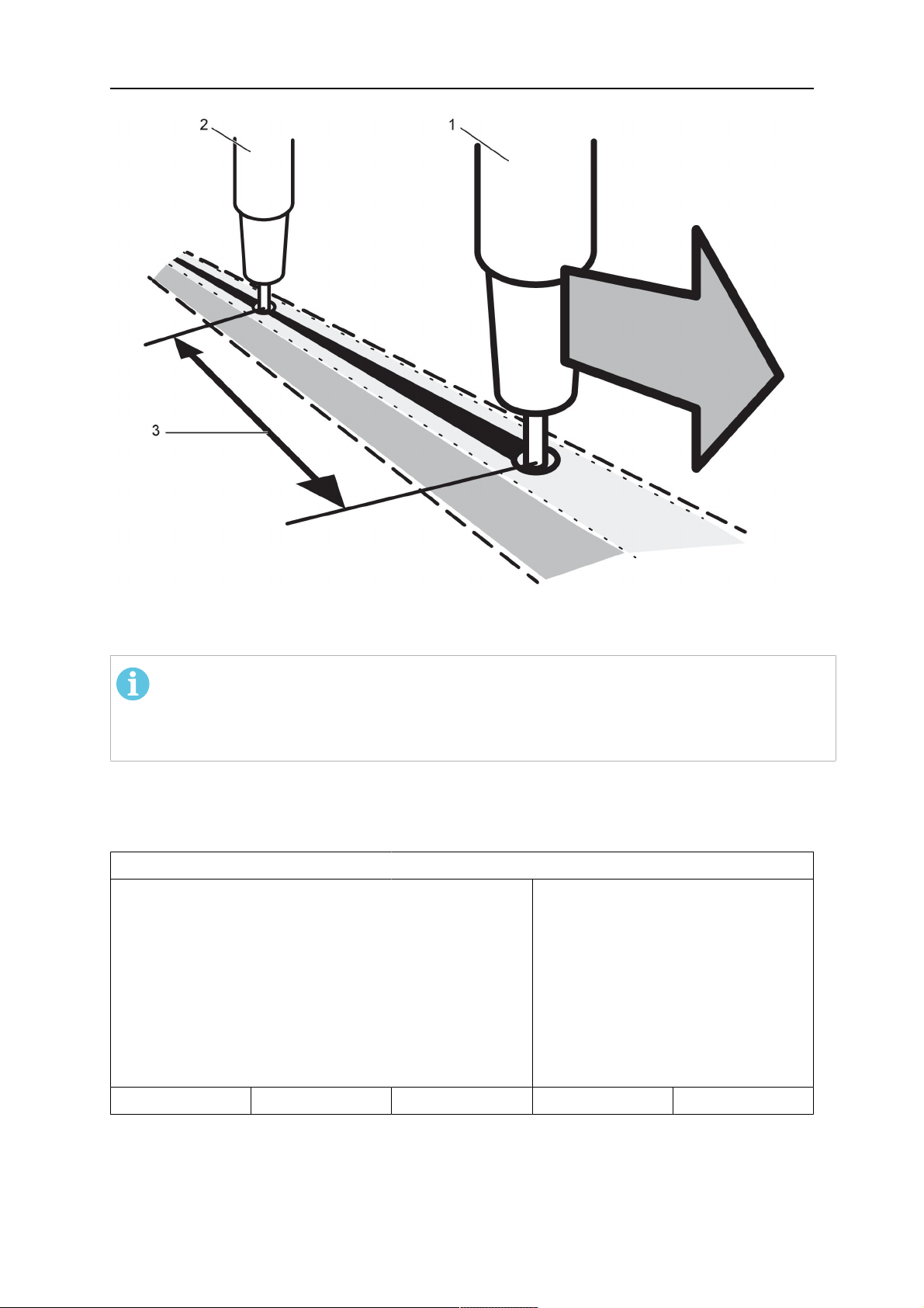
In order to weld with two welding heads, the WELD HEAD OFFSET function must be set.
WELD HEAD OFFSET is the distance in millimetres between the welding heads.
When you specify the distance between welding head 1 HEAD and welding head 2 TAIL, the
value is recalculated by the control unit to a time between when welding head 1 starts and
welding head 2 is to start.
The time that the control unit can calculate for the distance between the starting and stopping
of the welding power sources is a maximum of 65 seconds. This means that if, for example,
50 cm/min is specified, 2000 mm can be entered as the maximum WELD HEAD OFFSET.
This is so that time does not expire before welding head 2 reaches the start point.
0460 949 474
- 47 -
© ESAB AB 2021
9 CONFIGURATION MENU
1. HEAD 3. WELD HEAD OFFSET
2. TAIL
NOTE!
Ensure that both control units have the same settings for WELD HEAD OFFSET and
specify the same travel speed. The master control unit must be allocated HEAD and
the slave control unit TAIL. Travel motion is always controlled from master.
Specify the values to weld with two welding heads as follows:
Position the cursor on the WELDING HEAD row. Select whether the setting is to apply to
master control unit HEAD or slave control unit TAIL.
MACHINE CONFIGURATION
PRODUCT CODE
A2TF J1
WIRE FEED AXIS►
TRAVEL AXIS►
TANDEM
└ WELDING HEAD
└ WELD HEAD OFFSET
HEAD
20 mm
└ WITH I/O
ON
ON
QUIT
• Position the cursor on the WELD HEAD OFFSET row and specify the distance between
the two welding heads.
0460 949 474
- 48 -
© ESAB AB 2021

9 CONFIGURATION MENU
Example, I/O ON
1. Head, Welding head 1 (master) 3. WELD HEAD OFFSET
2. Tail, welding head 2 (slave)
Press Start, for welding head1.
• Welding head1 starts to weld.
• Welding head2 only starts welding when the start position for welding head1 has been
reached (the distance given in WELD HEAD OFFSET.
Press Stop, for welding head1.
• Welding head1 stops welding but continues travelling.
• Welding head2 stops welding once it reaches the point where equipment 1 stopped
welding (the distance given in WELD HEAD OFFSET.
• Welding is complete.
0460 949 474
- 49 -
© ESAB AB 2021

9 CONFIGURATION MENU
Example, I/O OFF
1. HEAD, Welding head 1 (master) 3. WELD HEAD OFFSET
2. TAIL, welding head 2 (slave)
Press Start, for welding head1 and welding head2 at the same time.
• Welding head1 starts to weld.
• Welding head2 starts to weld first when the start position for welding head1 has been
reached (the distance given WELD HEAD OFFSET).
Press stop, for welding head1 and welding head2 at the same time.
• Welding head1 stops welding but travel motion continues.
• Welding head2 stops welding when it has reached the point where equipment 1
stopped welding (the distance that is given in WELD HEAD OFFSET).
• Welding is complete.
9.3.7 Tandem for Aristo® 1000 power source
Used when welding with two or more welding heads. The welding heads are each controlled
by their own control unit (PEK).
Position the cursor on the TANDEM row and press ENTER. Select ON using the positioning
knob and press ENTER.
The front welding head is selected.
0460 949 474
- 50 -
© ESAB AB 2021

9 CONFIGURATION MENU
TANDEM
AC SYNC MASTER
PHASE SHIFT
TRAVEL CONTROL
TANDEM
└ WELDING HEAD
└ SYNCRONIZED WELD START
└ SYNCRONIZED AC WELD
The rear welding head is selected.
TANDEM
AC SYNC MASTER
└ PHASE SHIFT
TRAVEL CONTROL
TANDEM
└ WELDING HEAD
ON
ON
ON
HEAD
ON
ON
QUIT
OFF
90
OFF
ON
TAIL
└ SYNCRONIZED WELD START
└ SYNCRONIZED AC WELDING
20 mm
ON
QUIT
WELDING HEAD
Select whether the welding head is to be the front HEAD or rear TAIL.
AC SYNC MASTER
One power source in a tandem system has to be set as ACsynchronization master if
synchronized ACwelding is used. Preferably the first ACwelding power source is set as
ACsynchronization master.
TRAVEL CONTROL
Select whether the welding head is control the travel. Both the front and rear welding heads
can control the travel, but only one at a time.
SYNCRONIZED WELD START
If ON is selected it means that one only need start the control unit for the front welding head.
The rear one is started automatically. If OFF is selected all the welding heads must be
started using the relevant control unit.
SYNCRONIZED AC WELDING
Synchronized AC welding means that the frequency and balance, the AC pulses, are
synchronized to the same values for all welding heads in the tandem system.
WELD HEAD OFFSET
WELD HEAD OFFSET is the distance in millimetres between the welding heads. The weld
head offset should always be set, whether a synchronised welding start is selected or not. If
a non-synchronised welding start is selected, the offset is used to calculate a timedelay for
the welding start on the TAIL welding head.
0460 949 474
- 51 -
© ESAB AB 2021

9 CONFIGURATION MENU
1. HEAD, Welding head 1 (master) 3. WELD HEAD OFFSET
2. TAIL, welding head 2 (slave)
PHASE SHIFT (applies only to AC welding)
Phase shift means a phase offset in relation to the front welding head. The unit is degrees.
9.3.8 Parallel power sources (applies only to Aristo® 1000 power sources)
To be able to set up two power sources in parallel, only the two power sources that are to be
connected should have power on and be active on the CAN2 bus.
PARALLEL POWERSOURCES
PARALLEL POWERSOURCES
Parallel couple ID
Connect with slave
QUIT
Perform settings for parallel power sources as follows:
1. Set the PARALLEL POWERSOURCES function to ON.
2. Set Parallel couple ID. The first parallel couple is set to 1, the next parallel couple is
set to 2 etc.
3. Select menu line Connect with slave and press ENTER.
A message Connect appears.
4. Press ENTER again.
OFF
1
- -
0460 949 474
- 52 -
© ESAB AB 2021

9 CONFIGURATION MENU
PARALLEL POWERSOURCES
PARALLEL POWERSOURCES ON
Parallel couple ID
Connect with slave
QUIT
CONNECT
When the master and slave power sources are connected, the text Connected is presented.
9.3.9 ICE wire feed
NOTE!
ICE option is only available with purchasing of ICE license.
The option ICE WIRE FEEDON can be selected in the machine configuration menu. If ICE
wire feed is selected, the option ICE WIRE FEED AXIS appears.
MACHINE CONFIGURATION
PRODUCT CODE
WIRE FEED AXIS
ICE WIRE FEED AXIS►
FREE 2 AXIS
1
- -
TRAVEL AXIS►
TANDEM
ICE WIRE FEED
NODE ID SETTINGS►
The ICE wire feed axis settings must be identical to the wire feed axis.
ICE WIRE FEED AXIS
MOTOR
GEAR 1►
└ N 1
└ N 2
GEAR 2►
└ N 1
└ N 2
FEED ROLLER DIAM
OFF
ON
QUIT
5035 38 RPM
ON
156
1
ON
1
1
49 mm
ENCODER PULSES
LOW MANUAL SPEED
Motor is selected from a dropdown list with the following options:
0460 949 474
- 53 -
32 ppr
150 cm/min
QUIT
© ESAB AB 2021

9 CONFIGURATION MENU
5035 38 RPM
5035 68RPM
FHP 258
VEC80000
VEC40000
DUNKER1
DUNKER2
MET3B
VEC4000Par
4030-350
• GEAR 1 must be set to ON. The value cannot be OFF.
• GEAR 2 must normally be set to ON, but OFF can be selected.
• The values N1 and N2 under GEAR 1 and GEAR 2 are set with one of the three
settings knobs at the bottom of the panel. The interval for N1 and N2 depend on
selected motor.
• The diameter of the feed rollers FEED ROLLER DIAM is selected with any settings
knob. The interval depends on selected motor.
• The encoder for pulses ENCODER-PULSES is selected with any settings knob. The
interval is between 1 - 9998 ppr (ppr = pulses per revolution).
• LOW MANUAL SPEED is selected with any of the settings knobs. The interval is 1 1000 cm/min.
• HIGH MANUAL SPEED is selected with any of the settings knobs. The interval is 1 5000 cm/min.
9.3.10 Step function
STEP FUNCTION
STEP CONTROL
STEP DIRECTION
STEP LENGTH
STEP SPEED
NUMBER OF STEPS
OVERLAP
MANUAL STEP LENGTH
WHEEL DIAMETER
WELD DIAMETER
ROLL DIAMETER
STEP CONTROL ON or OFF
On/off setting of the step function
ON
TRIANGLE
76 mm
77 cm/min
10
10 mm
3 mm
1 mm
1 000 mm
1 000 mm
QUIT
STEP DIRECTION SQUARE or TRIANGLE
Setting of direction for the auto step execution
STEP LENGTH The length of one auto step (minimum setting 1mm)
0460 949 474
- 54 -
© ESAB AB 2021

9 CONFIGURATION MENU
STEP SPEED The travel speed of the auto step (minimum setting 3cm/min)
NUMBER OF STEPS The number of steps during one rotational turn.
OVERLAP The length of the overlap of one rotational turn.
MANUAL STEP LENGTH The length of one manual step (minimum setting 1mm)
(for singular manual adjustments during welding)
NOTE!
To be able to run the step function, STEP CONTROL must be in the ON position, the
EXT AXIS and AUTO STEP soft keys must be ON
If you want to have a restart of step, to restart step welding after a stop, press soft key
RESTART STEP before you press the AUTO STEP before you start to weld.
For example, if you have 100mm to next step, press STOP, change the wire, position the
object, press RESTART STEP, press AUTO STEP, and start to weld. Next step will be after
100mm.
When the “one turn switch” is activated, the step function executes one autostep in the
direction and with the speed and length specified by the STEP DIRECTION, STEP SPEED
and STEP LENGTH parameters.
If the FORCE STEP soft key is pushed, the step function executes one auto step in the
direction and with the speed and length specified by the STEP DIRECTION, STEP SPEED
and STEP LENGTH parameters.
If the square/triangle button is pushed, one manual step will be executed in the direction and
with the speed and length specified by the square/triangle, STEP SPEED and STEP
LENGTH parameters. This function can be used to make one small adjustment during
welding.
There is always a possibility to interrupt an auto step or manual step movement by pushing
the SQUARE or TRIANGLE button.
During the auto step or manual step movement, the LED above the square/triangle button is
on to indicate movement and direction.
Speed wheel settings
When the positioner and the speed wheel are ON the speed wheel (encoder) is at the
welding object.
When the positioner and the speed wheel are OFF the encoder is at the motor shaft.
When the roller bed and the speed wheel are ON the speed wheel (encoder) is at the roller
bed wheel.
When the roller bed and the speed wheel are OFF the encoder is at the motor shaft.
0460 949 474
- 55 -
© ESAB AB 2021

9 CONFIGURATION MENU
9.3.11 Intermittent welding
INTERMITTENT WELDING
INTERMITTENT WELDING
WELDING LENGTH
TRANSPORT LENGTH
NUMBER OF WELDS
QUIT
To activate the function set intermittent welding to ON. An intermittent welding sequence
consists of weld and transport. At the last weld in a sequence, the transport will not be
performed.
WELDING LENGTH is the length of the weld.
TRANSPORT LENGTH is the length of the transport after a weld has finished.
NUMBER OF WELDS is the number welds to be performed including transport. If the
number of welds is set to “0”, the intermittent welding sequence continues until the user
stops the welding using the red weld stop button.
9.3.12 Polarity (applies only to Aristo® 1000 power source)
In the POLARITY menu you can set the welding polarity.
ON
0 mm
0 mm
0
• To weld with positive polarity on the welding wire and negative polarity on the work
piece, select POSITIVE polarity.
• To weld with negative polarity on the welding wire and positive polarity on the work
piece, select NEGATIVE polarity.
9.3.13 Node id settings (applies only to Aristo® 1000 power source)
If there are I/O nodes in the system the ID numbers are given here.
NODE ID SETTINGS
I/O NODE 1 ID
I/O NODE 2 ID
17
25
QUIT
9.3.14 System information (applies only to Aristo® 1000 power source)
The SYSTEM INFORMATION menu shows active power sources connected via the
CAN2bus, if the power sources are in tandem or parallel mode and if they are configured as
master or slave.
SYSTEM INFORMATION
Active power sources on CAN2
PS id Tandem Parallel
0460 949 474
- 56 -
© ESAB AB 2021

9 CONFIGURATION MENU
SYSTEM INFORMATION
No contact with master power source
QUIT
9.4 Cable lengths (applies only to LAF and TAF power sources)
The arc voltage is affected by the impedance in the welding cables. The impedance is
affected by the length and area of the cables as well as by how they are routed. This is
especially prominent during AC welding.
Compensation for the voltage drop with long cables is maintained if the actual cable length is
specified.
The total cable length (weld cable and connector together) must be fed in.
Note! When using two cables, the areas must be combined for both cables.
This function is active during the start process before the power source has received a
measurement value that it can regulate at.
If ”Max OCV” has been selected this function is inactive.
9.5 Maintenance
MAIN MENU » CONFIGURATION » MAINTENANCE
In this menu you set how often the contact tip is to be changed. Specify the number of weld
starts after which the tip is to be changed by selecting the CONTACT TIP CHANGE
INTERVAL row and pressing ENTER. Change the value using the setting knobs. When the
interval has been passed, fault code 54 is displayed in the error log.
When TOTAL RUNNING TIME LIMIT is selected instead of the number of starts, an
authorised ESAB service technician is contacted.
MAINTENANCE
CONTACT TIP CHANGE INTERVAL
└ WELD COUNT
TOTAL RUNNING TIME LIMIT
└ TOTAL RUNNING TIME
0 Welds
0 Welds
0d:00:00:00
0d:00:00:00
QUIT
9.6 Measure–values filter factor
MAIN MENU » CONFIGURATION » MEASURE-VALUES FILTER FACTOR
This menu provides a filter factor for the measurement values of the welding current. The
higher filter factor value you choose, the more stable welding current measurement value
you will get. You can choose between filter factors 1, 2 and 4.
0460 949 474
- 57 -
© ESAB AB 2021

9 CONFIGURATION MENU
Position the cursor on the MEASURE-VALUES FILTER FACTOR row and press ENTER. A
pop-up menu shows filter factors ONE, TWO and FOUR. Select the preferred filter factor
using the positioning knob and press ENTER.
CONFIGURATION
LANGUAGE
CODE LOCK►
GENERAL CONFIGURATION►
MACHINE CONFIGURATION►
CABLE LENGTHS►
MAINTENANCE►
MEASURE-VALUES FILTER FACTOR
ONE
TWO
FOUR
ENGLISH
ONE
QUIT
0460 949 474
- 58 -
© ESAB AB 2021

10 TOOLS
10 TOOLS
MAIN MENU » TOOLS
This menu contains the following sub-menus:
• Event handling, see section "Event handling".
• Export/Import, see section "Export/Import".
• File manager, see section "File manager".
• Edit setting limits, see section "Setting limit editor".
• Edit measure limits, see section "Measure limits editor".
• Production statistics, see section "Production statistics".
• Quality functions, see section "Quality functions".
• Calendar, see section "Calendar".
• User accounts, see section "User accounts".
• Unit information, see section "Unit information".
10.1 Event handling
MAIN MENU » EVENT HANDLING
Fault management codes are used to indicate that a fault has occurred in the welding
process. Indicated in the display via a pop-up menu and an exclamation mark appears in
the upper right-hand corner of the display.
NOTE!
disappears from the display as soon as you enter the event log menu.
The Event handling menu has got two sub-menus, Event log (see section "Event log") and
Active errors (see section "Active errors").
EVENT HANDLING
EVENT LOG►
ACTIVE ERRORS►
QUIT
10.1.1 Event log
MAIN MENU » TOOLS » EVENT HANDLING » EVENT LOG
All errors that arise during the use of the welding equipment are documented as error
messages in the error log. Up to 99 error messages can be saved. If the error log becomes
full, i.e. if 99 error messages have been saved, the oldest message is automatically deleted
when the next fault occurs.
The following information can be read in the error log:
• The error number of the error
• The day on which the error occurred
• The time at which the error occurred
0460 949 474
- 59 -
© ESAB AB 2021
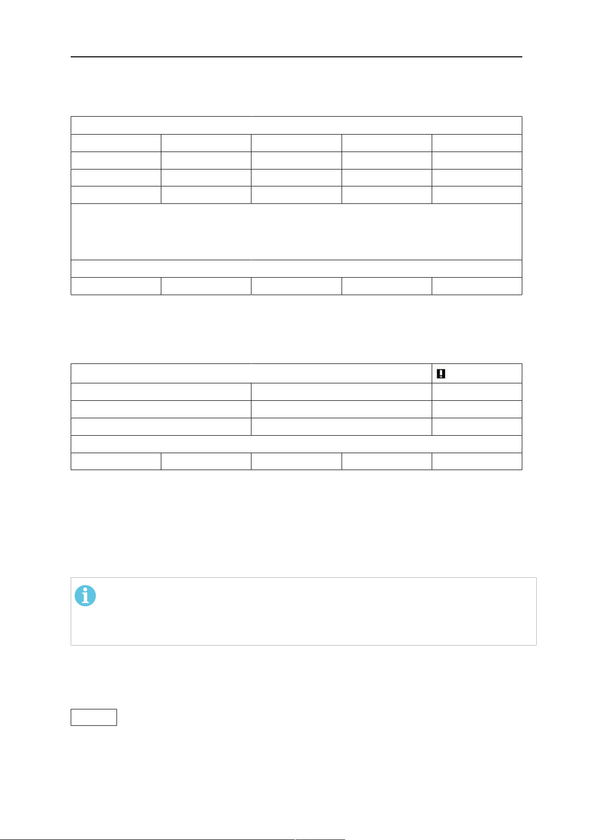
10 TOOLS
• The unit in which the error has occurred, see section "Unit IDs"
• The error's error management code, see section "Description of fault management
codes"
ERROR LOG
Index Date Time Unit Error
1 081120 11:24:13 8 19
2 081120 10:24:18 8 18
3 081121 13:24:18 8 17
Error in battery-driven memory
DELETE ALL QUIT
10.1.2 Active errors
MAIN MENU » TOOLS » EVENT HANDLING » ACTIVE ERRORS
The Active errors menu shows only the errors active for the moment.
ACTIVE ERRORS
Error nr Node ID Device type
78 1 powersource
152 1 powersource
Error nr 78
QUIT
10.1.3 Unit IDs
Explanation of unit IDs for LAF and TAF power source:
2= Power source
6= Wire feed and travel motion (motor board)
8= Control panel
NOTE!
The unit IDs specified above apply to LAF and TAF power sources, and constitutes an
example of unit IDs for Aristo®1000, as the nodes in an Aristo®1000 application
may have different ID numbers depending on the configuration of the equipment.
10.1.4 Description of fault management codes
The fault management codes that users can correct themselves are given below. If another
code appears, restart the machine and if the error persists, contact a service technician.
6 High temperature
The power source has overheated. Welding is cancelled. Welding is permitted again when the
temperature falls below the maximum temperature parameter.
1. Check that the cooling air inlets or outlets are not obstructed or clogged with dirt.
2. Check the duty cycle being used, to make sure that the equipment is not being overloaded.
0460 949 474
- 60 -
© ESAB AB 2021

10 TOOLS
7 Low welding current
The weld arc has been shut down due to too low welding current during the welding process.
1. Is reset at next weld start. If the error persists, send for a service technician.
8 Low battery voltage
Battery voltage too low. If the battery is not replaced, all stored data will be lost. This error does not
disable any functions.
1. Send for a service technician to replace the battery.
11 Speed error on a motor (wire feed, travel motor)
A motor cannot maintain its speed. Welding stops.
1. Check that the wire feed has not jammed or runs too fast. If the error persists, send for a service
technician.
2. If the error persists, send for a service technician.
12 Internal communication error (warning)
The load on the system's CAN-bus is temporarily too high. The power source may have lost contact
with the control unit
1. Check that all the equipment is correctly connected. If the error persists, send for a service
technician.
14 Communication error
The system's CAN bus has temporarily ceased to work due to excessive load.
The current welding process is stopped.
1. Check the equipment to ensure that only one wire feed unit or remote control unit is connected.
2. If the error is repeated, send for a service technician.
17 Lost contact with the unit
Lost contact with a unit.
1. Check wiring and the connector between the control unit and power source.
32 No gas flow
Start prevented.
1. Check the gas valve, hoses and connectors.
43 High welding current
Power source have switched off the welding process because the current has exceeded the maximum
current parameter for the power source.
1. Is reset at next weld start. If the error persists, send for a service technician.
44 Current servo saturation
The welding process has stopped because it has not advanced within 10 seconds.
1. Is reset at next weld start. If the error persists, send for a service technician.
168 A motor has stopped
There are no pulses from the motor pulse transducer.
0460 949 474
- 61 -
© ESAB AB 2021

10 TOOLS
For LAF and TAF: 168 = Motor M1 (Wire feeder motor), 169 = Motor M2 (Travel motor).
1. Check the motor cables. Replace the pulse transducer.
169 A motor has stopped
There are no pulses from the motor pulse transducer.
For LAF and TAF: 168 = Motor M1 (Wire feeder motor), 169 = Motor M2 (Travel motor).
1. Check the motor cables. Replace the pulse transducer.
2310 Current servo saturation
The power source has temporarily delivered maximum current.
1. If the error persists, try lowering the weld data.
3205 High DC voltage
1. Check if the main voltage is too low or too high.
4201 High temperature
The power source has overheated. Welding is cancelled. Welding is permitted again when the
temperature falls below the maximum temperature parameter.
1. Check that the cooling air inlets or outlets are not obstructed or clogged with dirt.
2. Check the duty cycle being used, to make sure that the equipment is not being overloaded.
4202 High temperature
The power source has overheated. Welding is cancelled. Welding is permitted again when the
temperature falls below the maximum temperature parameter.
1. Check that the cooling air inlets or outlets are not obstructed or clogged with dirt.
2. Check the duty cycle being used, to make sure that the equipment is not being overloaded.
4203 High temperature
The power source has overheated. Welding is cancelled. Welding is permitted again when the
temperature falls below the maximum temperature parameter.
1. Check that the cooling air inlets or outlets are not obstructed or clogged with dirt.
2. Check the duty cycle being used, to make sure that the equipment is not being overloaded.
5010 High inductance
Inductance is too high, depending on long welding cables and/or high weld data.
1. Adjust the welding data.
8117 Lost contact with the unit
Lost contact with a unit.
1. Check wiring and the connector between the control unit and power source.
8411,
Wire speed motor error
subcode 0
A motor cannot maintain its speed. Welding stops.
1. Check that the wire feed has not jammed or runs too fast. If the error persists, send for a service
technician.
0460 949 474
- 62 -
© ESAB AB 2021

10 TOOLS
8411,
Travel speed motor error
subcode 1
There are no pulses from the motor pulse transducer.
1. Check the motor cables. Replace the pulse transducer.
10.2 Export/Import
MAIN MENU » TOOLS » EXPORT / IMPORT
In the Export/Import menu, it is possible to transfer information to and from the control panel
via a USB memory.
The following information can be transferred:
• WELD DATA SETS EXPORT / IMPORT
• SYSTEM SETTING EXPORT / IMPORT
• SETTING LIMITS EXPORT / IMPORT
• MEASURE LIMITS EXPORT / IMPORT
• ERROR LOG EXPORT
• QUALITY FUNCTION LOG EXPORT
• PRODUCTION STATISTICS EXPORT
Carry out the following to save on a USB memory:
Insert the USB memory into the control unit.
Select the row with the information that is to be transferred. Press EXPORT or IMPORT,
depending on whether the information is to be exported or imported.
EXPORT/IMPORT
WELD DATA SETS
SYSTEM SETTINGS
SETTING LIMITS
MEASURE LIMITS
ERROR LOG
QUALITY FUNCTION LOG
PRODUCTION STATISTICS
EXPORT IMPORT QUIT
10.3 File manager
MAIN MENU » TOOLS » FILE MANAGER
In the file manager it is possible to manage information on a USB memory (C:\). File
manager makes it possible to delete and copy weld data and quality data manually.
When the USB memory is connected, the display shows the memory's default folder if one is
not previously selected.
The control panel remembers where you were the last time you used file manager, so that
you return to the same place in the file structure when you come back.
0460 949 474
- 63 -
© ESAB AB 2021

10 TOOLS
FILE MANAGER
..
NEW FOLDER
QData.xml
INFO UPDATE ALT. QUIT
• In order to ascertain how much storage space remains for the memory, use the INFO
function.
• Update the information by pressing UPDATE.
• When you want to delete, change name, create new folder, copy or paste, press ALT. A
list then appears from which you can choose. If (..) or a folder is selected, you can only
create a new folder or paste in a file that you have previously copied. If you have
selected a file, the options RENAME, COPY or PASTE will be added if you have
previously copied a file.
Select a folder or file and press ALT.
FILE MANAGER
..
WeldData
NEW FOLDER
ErrorLog.xml
QData.xml
~Weldoffice.dat
INFO UPDATE ALT. QUIT
This list is displayed when you have pressed ALT.
COPY
PASTE
DELETE
RENAME
NEW FOLDER
10.3.1 Delete a file/folder
Select the file or folder that is to be deleted and press ALT.
Select DELETE and press ENTER.
DELETE
RENAME
NEW FOLDER
0460 949 474
- 64 -
© ESAB AB 2021

10 TOOLS
The file/folder is now removed. In order to delete a folder it must be empty, i.e. first delete the
files contained in the folder.
10.3.2 Rename a file/folder
Select the file or folder that is to be renamed and press ALT.
Select RENAME and press ENTER.
DELETE
RENAME
NEW FOLDER
A keyboard appears in the display. Use the positioning knob to change row and the arrows to
move left and right. Select the character/function that is to be used and press ENTER.
10.3.3 Create new folder
Select where the new folder is to be located and press ALT.
Select NEW FOLDER and press ENTER.
DELETE
RENAME
NEW FOLDER
A keyboard then appears in the display. Use the positioning knob to change row and the
arrows to move left and right. Select the character/function that is to be used and press
ENTER.
10.3.4 Copy and paste files
Select the file that is to be copied and press ALT.
Select COPY and press ENTER.
COPY
PASTE
DELETE
RENAME
NEW FOLDER
Position the cursor in the folder in which the copied file is to be located and press ALT.
Select PASTE and press ENTER.
COPY
PASTE
DELETE
RENAME
NEW FOLDER
The copy is saved as Copy of plus the original name, e.g. Copy of WeldData.awd.
0460 949 474
- 65 -
© ESAB AB 2021

10 TOOLS
10.4 Setting limit editor
MAIN MENU » TOOLS » SETTING LIMIT EDITOR
In this menu you set your own max. and min. values for various welding methods. The limits
cannot be above or below the values for which the power source is dimensioned. There are
50 storage points. Select the row for an empty storage point and press ENTER. Select
process by pressing ENTER and select the welding process using the positioning knob and
press ENTER.
The maximum and minimum values for arc voltage, wire feed speed, travel speed and
welding current can be selected for all processes.
EDIT LIMITS
PROCESS
VOLTAGE
VOLTAGE
WIRE SPEED
WIRE SPEED
TRAVEL SPEED
TRAVEL SPEED
CURRENT
CURRENT
STORE DELETE QUIT
LIMITS
1 SAW
2 GMAW
3 GOUGING
4 -
SAW
MIN 17.0
MAX 47.0
MIN 50
MAX 970
MIN 100
MAX 2400
MIN 70
MAX 1500
5 -
6 -
7 -
17.0 - 47.0 Volt , 50 - 970 cm/min
100 - 2400 cm/min , 70 - 1500 Amp
QUIT
When the values have been adjusted, press STORE. When asked if the limit value is to be
saved at the selected storage point, press NO or YES. The storage point's values can be
seen under the line at the bottom.
With the AUTO soft key, the parameters are set automatically according to the most recently
used parameters.
When asked if the limit settings are to be set automatically, press NO or YES and then
STORE if the setting is to be retained.
0460 949 474
- 66 -
© ESAB AB 2021

10 TOOLS
10.5 Measure limits editor
MAIN MENU » TOOLS » MEASURE LIMITS EDITOR
In this menu you set your own measurement values for the various welding methods. There
are 50 storage points. Select the row for an empty storage point and press ENTER. Select
PROCESS by pressing ENTER and select the welding process using the positioning knob
and press ENTER.
The following values can be selected:
• arc voltage: min, max
• wire feed speed: min, max
• welding current: min, max
• travel speed: min, max
• energy per unit length: min, max
Set the desired value using the setting knobs and press STORE.
In the dialogue box, you are asked if you want to store the selected storage point. Press YES
to save the value. The storage point's values can be seen under the line at the bottom.
MEASURE LIMITS
1 SAW
2 GMAW
3 -
4 -
5 -
6 -
7 -
0.0 - 46.9 Volt , 0 - 2495 cm/min
3 - 994 cm/min , 3 - 990 Amp
5 - 500 kJ/min
QUIT
With the AUTO soft key, the parameters are set automatically according to the most recently
used measurement values.
When asked if the measurement values are to be set automatically, press NO or YES and
then STORE if the setting is to be retained.
10.6 Production statistics
MAIN MENU » TOOLS » PRODUCTION STATISTICS
The production statistics will keep track of the total arc time, the total amount of material and
the number of welds since the most recent reset. They will also keep track of the arc time
and the amount of material used in the most recent weld. For information purposes, the
melted wire material per length unit that has been calculated and when the most recent reset
occurred are also displayed.
0460 949 474
- 67 -
© ESAB AB 2021
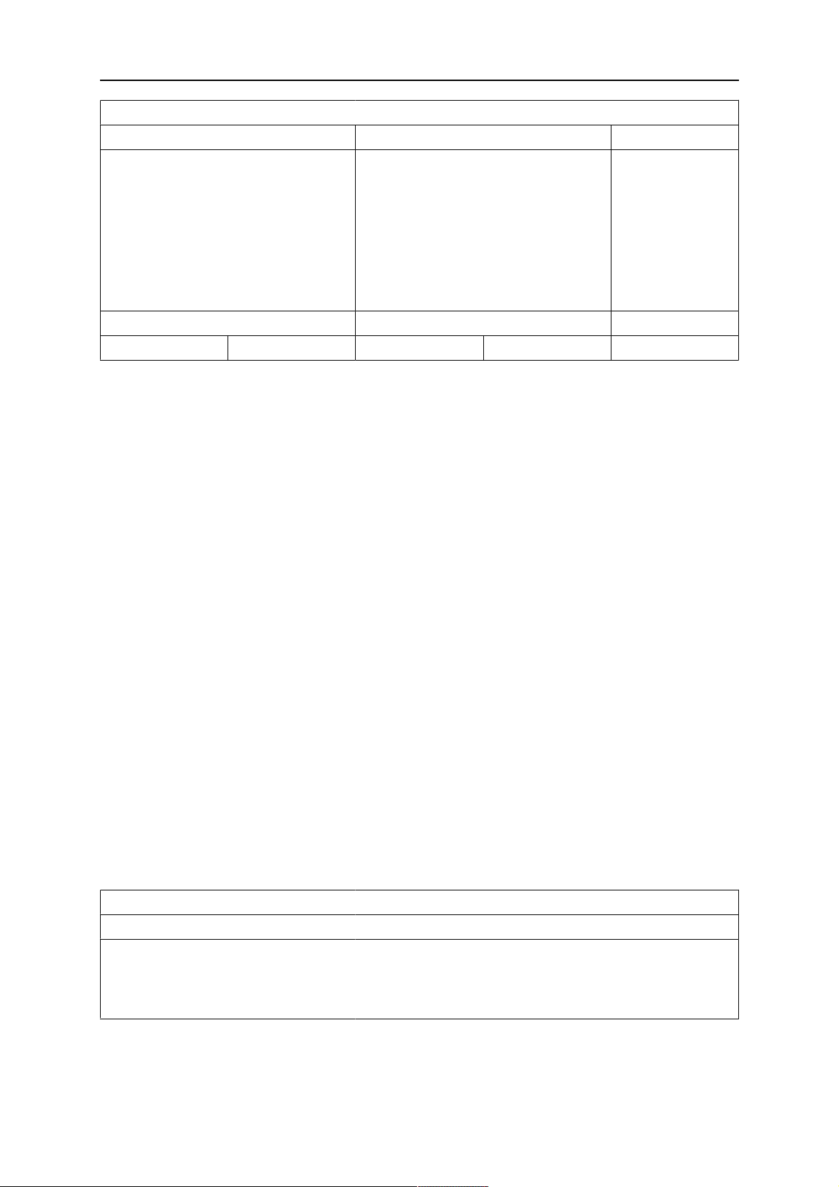
10 TOOLS
PRODUCTION STATISTICS
LAST WELD TOTAL
ARCTIME
CONSUMED WIRE
BASED ON
NUMBER OF WELDS
CONSUMED ICE WIRE
DEPOSITION RATE
0s
0g
1g/m
0 kg/h
0s
0g
0
0 kg/h
LAST RESET 081114 08:38:03
RESET UPDATE QUIT
When you press RESET, all counters are reset. Date and time show the most recent reset.
If you do not reset the counters, these are all automatically reset when one of them has
reached its maximum value.
Maximum counter values
Time 999 hours, 59 minutes, 59 seconds
Weight 13350000 grams
Quantity 65535
10.7 Quality functions
MAIN MENU » TOOLS » QUALITY FUNCTIONS
Quality functions keep track of various interesting weld data for individual welds.
These functions are:
• Time of welding start.
• Duration of welding.
• Maximum, minimum and average current during welding.
• Maximum, minimum and average voltage during welding.
• Maximum, minimum and average energy per unit length during welding.
The number of welds since the most recent reset is displayed in the row at the bottom.
Information can be stored about a maximum of 100 welds. In the event of more than 100
welds, the first one is overwritten.
The most recently noted weld is presented in the display, although it is also possible to
browse between other noted welds. All logs are deleted when you press RESET.
QUALITY FUNCTIONS
#WELD: 1 / 4
START 20190807 15:59:14
WELD TIME 00:00:20 WELD DATA:
HEAT INPUT: 3.12 kJ/min
0460 949 474
- 68 -
© ESAB AB 2021
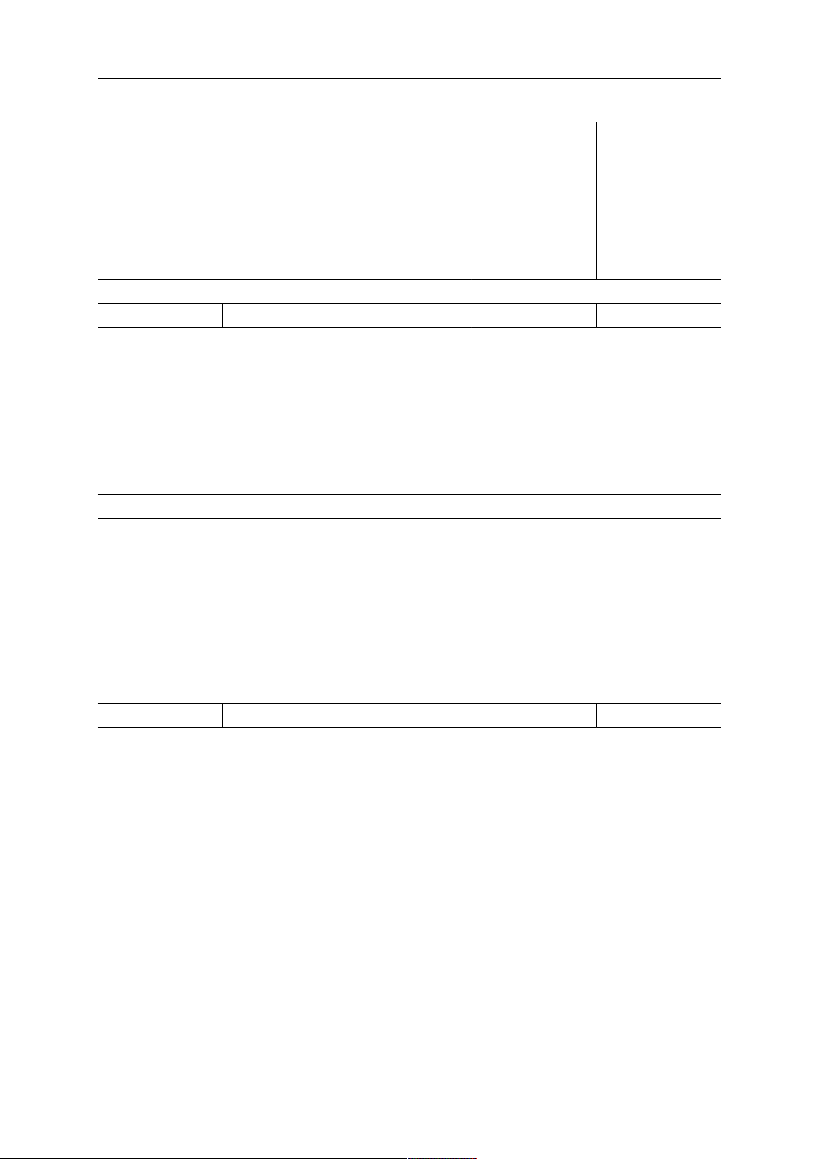
10 TOOLS
QUALITY FUNCTIONS
I (Amp)
U (V)
Q (kJ/min)
V(t) (cm/min)
V(w) (cm/min)
MAX
293.00
41.50
7.00
0.00
0.00
MIN
243.00
16.20
0.00
0.00
0.00
AVE.
289.00
39.40
2.00
0.00
0.00
NUMBER OF WELDS SINCE RESET: 4
RESET UPDATE QUIT
10.7.1 Store quality data
MAIN MENU » TOOLS » EXPORT / IMPORT
The files that are produced in the control panel are stored as xml files. The USB memory
must be formatted as FAT32 in order to work.
Insert a USB memory in the control panel, see section "File manager".
Select QUALITY FUNCTION LOG, press EXPORT.
EXPORT/IMPORT
WELD DATA SETS
SYSTEM SETTINGS
SETTING LIMITS
MEASURE LIMITS
ERROR LOG
QUALITY FUNCTION LOG
PRODUCTION STATISTICS
EXPORT QUIT
The entire set of quality data (information about the 100 most recent welds) that is stored in
the control panel is now saved on the USB memory.
The file is in a folder called QData. QData is created automatically when you insert a USB
memory.
10.7.2 Import system settings
When changing between Aristo® 1000 and LAF/TAF power sources use SYSTEM
SETTINGS to import system settings.
When EXPORT/IMPORT is selected you can import settings by marking the SYSTEM
SETTINGS using the positioning knob and pressing IMPORT.
0460 949 474
- 69 -
© ESAB AB 2021
10 TOOLS
EXPORT/IMPORT
WELD DATA SETS
SYSTEM SETTINGS
SETTING LIMITS
MEASURE LIMITS
ERROR LOG
QUALITY FUNCTION LOG
PRODUCTION STATISTICS
EXPORT IMPORT QUIT
IMPORT
10.8 Calendar
MAIN MENU » TOOLS » CALENDAR
Date and time are set here.
Select the row that is to be set: YEAR, MONTH, DAY, HOUR, MINUTES or SECONDS. Set
the correct value using one of the setting knobs. Press SET.
DATE & TIME
YEAR
MONTH
2019
NOV
DAY
HOUR
MINUTES
SECONDS
20100115 10:48:59
SET QUIT
10.9 User accounts
MAIN MENU » TOOLS » USER ACCOUNTS
Occasionally it is particularly important from a quality perspective that the product cannot be
used by unauthorised parties.
User name, account level and password are registered in this menu.
21
10
45
55
Select USER NAME and press ENTER. Step down to an empty row and press ENTER. Key
in a new user name on the keyboard using the positioning knob and the arrows and ENTER.
0460 949 474
- 70 -
© ESAB AB 2021

10 TOOLS
USER ACCOUNTS
USER NAME
└ACCOUNT LEVEL
ADMINISTRATOR
ADMIN
└PASSWORD
USER ACCOUNTS
OFF
STORE DELETE QUIT
There is space for 16 user accounts. In the quality data files it will be evident which users
have executed a particular weld.
Under ACCOUNT LEVEL choose from:
ADMINISTRATOR FULL ACCESS (can add new users)
SENIOR USER can access everything except: MACHINE CONFIGURATION, USER
ACCOUNTS and NETWORK SETTINGS
NORMAL USER can access: MAINTENANCE in CONFIGURATION menu. UNIT
INFORMATION in TOOLS menu. VOLTAGE, CURRENT / WIRE
FEED, TRAVEL SPEED and WELDING DIRECTION in SETTINGS
menu.
In the PASSWORD row, key in a password using the keyboard. When the power source is
switched on and the control panel activated, you are asked in the display to enter your
password.
If you choose not to have this function, but instead want the power source and control panel
to be unlocked for all users, select USER ACCOUNTS OFF.
10.10 Unit information
MAIN MENU » TOOLS » UNIT INFORMATION
In this menu you can see the following information:
• Machine ID
• Node ID (regarding node IDs specified below, see section "Unit IDs")
2 = power source
6 = wire feed and travel motion (motor board)
8 = control panel
• Software version
UNIT INFORMATION
Machine ID Node ID Software Version
44
8
1.00A
0460 949 474
23
5
- 71 -
2
6
2.00A
1.18A
© ESAB AB 2021

10 TOOLS
UNIT INFORMATION
SETTING WELD DATA UNIT
QUIT
0460 949 474
- 72 -
© ESAB AB 2021
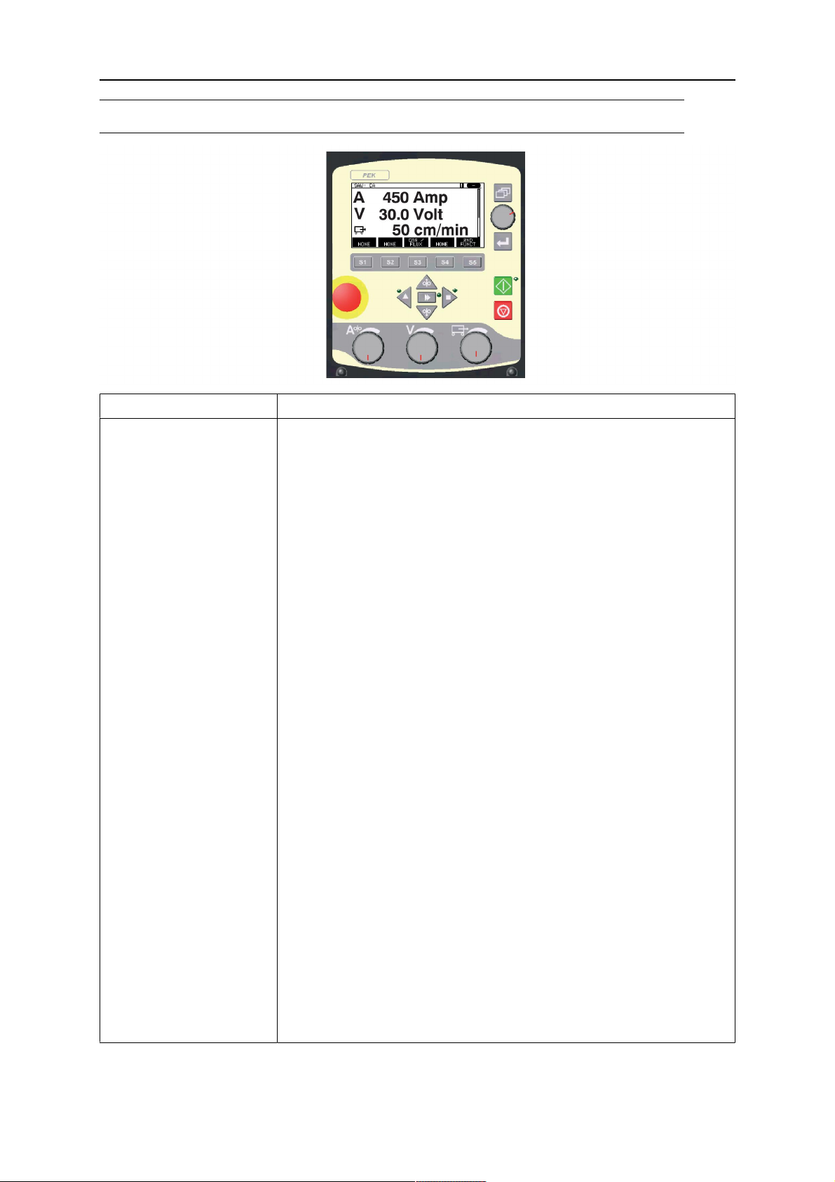
ORDERING NUMBERS
ORDERING NUMBERS
Ordering no. Denomination
0460 504 880
0460 949 470
0460 949 471
0460 949 472
0460 949 473
0460 949 474
0460 949 475
0460 949 476
0460 949 477
0460 949 478
0460 949 479
0460 949 480
0460 949 481
0460 949 482
0460 949 483
Control unit PEK
Instruction manual SE
Instruction manual DK
Instruction manual NO
Instruction manual FI
Instruction manual GB
Instruction manual DE
Instruction manual FR
Instruction manual NL
Instruction manual ES
Instruction manual IT
Instruction manual PT
Instruction manual GR
Instruction manual PL
Instruction manual HU
0460 949 484
0460 949 485
0460 949 486
0460 949 489
0460 949 490
0460 949 491
0460 949 492
0460 949 493
Instruction manual CZ
Instruction manual SK
Instruction manual RU
Instruction manual EE
Instruction manual LV
Instruction manual SI
Instruction manual LT
Instruction manual CN
Instruction manuals are available on the Internet at www.esab.com
0460 949 474
- 73 -
© ESAB AB 2021

ESAB AB, Lindholmsallén 9, Box 8004, 402 77 Gothenburg, Sweden, Phone +46 (0) 31 50 90 00
http://manuals.esab.com
For contact information visit esab.com
 Loading...