

Page 1

100i, 200i, 300i, and 400i
Plasma System
Service Manual
Article Number: 0560956456
Revision Date: June 14, 2016
Revision Number: AA
Language: ENG
Page 2

WE APPRECIATE YOUR BUSINESS!
Congratulations on your new ESAB product. We are proud to have you as our customer and will
strive to provide you with the best service and reliability in the industry. This product is backed by
our extensive warranty and world-wide service network. To locate your nearest distributor or service
agency call 1-800-ESAB-123, or visit us on the web at www.ESAB.com.
This instruction manual has been designed to instruct you on the correct use and operation of your
ESAB product. Your satisfaction with this product and its safe operation is our ultimate concern.
Therefore please take the time to read the entire manual, especially the Safety Precautions. They will
help you to avoid potential hazards that may exist when working with this product.
YOU ARE IN GOOD COMPANY!
The Brand of Choice for Contractors and Fabricators Worldwide.
ESAB is a Global Brand of manual and mechanized Plasma Cutting Products.
We distinguish ourselves from our competition through market-leading, dependable products that
have stood the test of time. We pride ourselves on technical innovation, competitive prices, excellent delivery, superior customer service and technical support, together with excellence in sales and
marketing expertise.
Above all, we are committed to developing technologically advanced products to achieve a safer
working environment within the welding industry.
Page 3

!
WARNING
Read and understand this entire Manual and your employer’s safety practices
before installing, operating, or servicing the equipment.
While the information contained in this Manual represents the Manufacturer’s
best judgement, the Manufacturer assumes no liability for its use.
Plasma Cutting Power Supply with Automated Gas Control 100i / 200i / 300i / 400i
Published by:
ESAB Welding and Cutting Products.
2800 Airport Rd.
Denton, Texas 76207
www.ESAB.com
© Copyright 2016 by ESAB Welding and Cutting Products.
All rights reserved.
Reproduction of this work, in whole or in part, without written permission of the publisher
is prohibited.
The publisher does not assume and hereby disclaims any liability to any party for any loss
or damage caused by any error or omission in this manual, whether such error results from
negligence, accident, or any other cause.
Original Publication Date: June 14, 2016
Revision Date:
Record the following information for Warranty purposes:
Where Purchased: ___________________________________
Purchase Date:______________________________________
Power Supply Serial #:_______________________________
Torch Serial #:_______________________________________
Page 4

Be sure this information reaches the operator.
You can get extra copies through your supplier.
CAUTION
These INSTRUCTIONS are for experienced operators. If you are not fully familiar with
the principles of operation and safe practices for arc welding and cutting equipment,
we urge you to read our booklet, “Precautions and Safe Practices for Arc Welding,
Cutting, and Gouging,” Booklet F52-529. Do NOT permit untrained persons to install,
operate, or maintain this equipment. Do NOT attempt to install or operate this equipment until you have read and fully understand these instructions. If you do not fully
understand these instructions, contact your supplier for further information. Be sure
to read the Safety Precautions before installing or operating this equipment.
USER RESPONSIBILITY
This equipment will perform in conformity with the description thereof contained in this manual and accompanying
labels and/or inserts when installed, operated, maintained and repaired in accordance with the instructions provided. This
equipment must be checked periodically. Malfunctioning or poorly maintained equipment should not be used. Parts that
are broken, missing, worn, distorted or contaminated should be replaced immediately. Should such repair or replacement
become necessary, the manufacturer recommends that a telephone or written request for service advice be made to the
Authorized Distributor from whom it was purchased.
This equipment or any of its parts should not be altered without the prior written approval of the manufacturer. The
user of this equipment shall have the sole responsibility for any malfunction which results from improper use, faulty maintenance, damage, improper repair or alteration by anyone other than the manufacturer or a service facility designated by
the manufacturer.
READ AND UNDERSTAND THE INSTRUCTION MANUAL BEFORE INSTALLING OR
PROTECT YOURSELF AN D OTHERS!
!
OPERATING.
Page 5

ASSUREZ-VOUS QUE CETTE INFORMATION EST DISTRIBUÉE À L’OPÉRATEUR.
ATTENTION
VOUS POUVEZ OBTENIR DES COPIES SUPPLÉMENTAIRES CHEZ VOTRE FOURNISSEUR.
Les INSTRUCTIONS suivantes sont destinées aux opérateurs qualiés seulement.
Si vous n’avez pas une connaissance approfondie des principes de fonctionnement
et des règles de sécurité pour le soudage à l’arc et l’équipement de coupage, nous
vous suggérons de lire notre brochure « Precautions and Safe Practices for Arc Welding, Cutting and Gouging, » Brochure F52-529. Ne permettez PAS aux personnes
non qualiées d’installer, d’opérer ou de faire l’entretien de cet équipement. Ne tentez
PAS d’installer ou d’opérer cet équipement avant de lire et de bien comprendre ces
instructions. Si vous ne comprenez pas bien les instructions, communiquez avec
votre fournisseur pour plus de renseignements. Assurez-vous de lire les Règles de
Sécurité avant d’installer ou d’opérer cet équipement.
RESPONSABILITÉS DE L’UTILISATEUR
Cet équipement opérera conformément à la description contenue dans ce manuel, les étiquettes d’accompagnement
et/ou les feuillets d’information si l’équipement est installé, opéré, entretenu et réparé selon les instructions fournies. Vous
devez faire une vérication périodique de l’équipement. Ne jamais utiliser un équipement qui ne fonctionne pas bien ou n’est
pas bien entretenu. Les pièces qui sont brisées, usées, déformées ou contaminées doivent être remplacées immédiatement.
Dans le cas où une réparation ou un remplacement est nécessaire, il est recommandé par le fabricant de faire une demande
de conseil de service écrite ou par téléphone chez le Distributeur Autorisé de votre équipement.
Cet équipement ou ses pièces ne doivent pas être modiés sans permission préalable écrite par le fabricant. L’utilisa-
teur de l’équipement sera le seul responsable de toute défaillance résultant d’une utilisation incorrecte, un entretien fautif, des
dommages, une réparation incorrecte ou une modication par une personne autre que le fabricant ou un centre de service
désigné par le fabricant.
ASSUREZ-VOUS DE LIRE ET DE COMPRENDRE LE MANUEL D’UTILISATION AVANT
!
D’INSTALLER OU D’OPÉRER L’UNITÉ.
PROTÉGEZ-VOUS ET LES AUTRES!
Page 6

This Page Intentionally Blank
Page 7

TABLE OF CONTENTS
SECTION 1: SAFETY ........................................................................................ 1-1
1.01 Safety Precautions - ENGLISH ........................................................................ 1-1
1.02 Précautions de sécurité - FRENCH CANADIAN ............................................... 1-6
SECTION 2: TORCH MAINTENANCE ................................................................... 2-1
2.01 Coolant Leak Trouble-Shooting ...................................................................... 2-1
APPENDIX 1: CNC - CONTROL MODULE PCB CONNECTIONS ....................................... A-1
APPENDIX 2: CNC ......................................................................................... A-2
CNC functions ............................................................................................................... A-2
CNC Input / Output Descriptions ................................................................................... A-4
Simplified CNC Circuit ...................................................................................................A-6
CNC Connections .......................................................................................................... A-8
APPENDIX 3: GSC CONTROL PCB LAYOUT ............................................................ A-9
APPENDIX 4: DPC CONTROL PCB LAYOUT ...........................................................A-10
APPENDIX 5: GSC / DPC POWER SUPPLY PCB LAYOUT ...........................................A-11
APPENDIX 6: CCM CPU PCB LAYOUT ..................................................................A-12
APPENDIX 7: CCM I/O PCB LAYOUT ...................................................................A-14
APPENDIX 8: PILOT PCB LAYOUT ......................................................................A-16
APPENDIX 9: RELAY AND INTERFACE PCB LAYOUT .................................................A-18
APPENDIX 10: DISPLAY PCB LAYOUT .................................................................A-20
APPENDIX 11: SYSTEM BIAS PCB LAYOUT ...........................................................A-22
APPENDIX 12: MAIN INVERTER BOTTOM PCB LAYOUT ............................................A-24
APPENDIX 13: MAIN INVERTER TOP PCB LAYOUT ..................................................A-26
APPENDIX 14: CONTROL AND FAULT PCB LAYOUT .................................................A-28
APPENDIX 15: CAP BIAS BOTTOM PCB LAYOUT .....................................................A-30
APPENDIX 16: CAP BIAS TOP PCB LAYOUT ..........................................................A-31
APPENDIX 17: SUPPRESSOR PCB LAYOUT ...........................................................A-32
APPENDIX 18: COOLING DIAGRAM ....................................................................A-33
APPENDIX 19: REMOTE ARC STARTER SCHEMATIC ................................................A-34
APPENDIX 20: SCHEMATIC, DFC AUTO GAS BOX SYSTEM .........................................A-36
APPENDIX 21: SYSTEM SCHEMATIC 100A, 380-415V PG 1 ........................................A-38
APPENDIX 22: SYSTEM SCHEMATIC 100A, 380-415V PG 2 ........................................A-40
APPENDIX 23: SYSTEM SCHEMATIC 200A, 380-415V PG 1 ........................................A-42
Page 8

TABLE OF CONTENTS
APPENDIX 24: SYSTEM SCHEMATIC 200A, 380-415V PG 2 ........................................A-44
APPENDIX 25: SYSTEM SCHEMATIC 300A, 380-415V PG 1 ........................................A-46
APPENDIX 26: SYSTEM SCHEMATIC 300A, 380-415V PG 2 ........................................A-48
APPENDIX 27: SYSTEM SCHEMATIC 400A, 380-415V PG 1 ........................................A-50
APPENDIX 28: SYSTEM SCHEMATIC 400A, 380-415V PG 2 ........................................A-52
APPENDIX 29: ADVANCED TROUBLESHOOTING .....................................................A-54
APPENDIX 30: HE 400 CONNECTION ..................................................................A-88
APPENDIX 31: PUBLICATION HISTORY ................................................................A-92
Page 9

iSERIES 100 /200 /300 /400
SECTION 1: SAFETY
1.01 Safety Precautions - ENGLISH
WARNING: These Safety Precautions are for your protection. They summarize precautionary information
from the references listed in Additional Safety Information section. Before performing any installation or
!
operating procedures, be sure to read and follow the safety precautions listed below as well as all other
manuals, material safety data sheets, labels, etc. Failure to observe Safety Precautions can result in injury or death.
PROTECT YOURSELF AND OTHERS -- Some welding, cutting, and gouging processes are noisy
and require ear protection. The arc, like the sun, emits ultraviolet (UV) and other radiation and can
injure skin and eyes. Hot metal can cause burns. Training in the proper use of the processes and
equipment is essential to prevent accidents. Therefore:
1. Always wear safety glasses with side shields in any work area, even if welding helmets, face shields, and
goggles are also required.
2. Use a face shield fitted with the correct filter and cover plates to protect your eyes, face, neck, and ears
from sparks and rays of the arc when operating or observing operations. Warn bystanders not to watch
the arc and not to expose themselves to the rays of the electric-arc or hot metal.
3. Wear flameproof gauntlet type gloves, heavy long-sleeve shirt, cuffless trousers, high-topped shoes, and
a welding helmet or cap for hair protection, to protect against arc rays and hot sparks or hot metal. A
flameproof apron may also be desirable as protection against radiated heat and sparks.
4. Hot sparks or metal can lodge in rolled up sleeves, trouser cuffs, or pockets. Sleeves and collars should
be kept buttoned, and open pockets eliminated from the front of clothing.
5. Protect other personnel from arc rays and hot sparks with a suitable non-flammable partition or curtains.
6. Use goggles over safety glasses when chipping slag or grinding. Chipped slag may be hot and can fly far.
Bystanders should also wear goggles over safety glasses.
FIRES AND EXPLOSIONS -- Heat from flames and arcs can start fires. Hot slag or sparks can also cause
fires and explosions. Therefore:
1. Remove all combustible materials well away from the work area or cover the materials with a protective
non-flammable covering. Combustible materials include wood, cloth, sawdust, liquid and gas fuels, solvents, paints and coatings, paper, etc.
2. Hot sparks or hot metal can fall through cracks or crevices in floors or wall openings and cause a hidden smoldering fire or fires on the floor below. Make certain that such openings are protected from hot
sparks and metal.“
3. Do not weld, cut or perform other hot work until the work piece has been completely cleaned so that there
are no substances on the work piece which might produce flammable or toxic vapors. Do not do hot work
on closed containers. They may explode.
4. Have fire extinguishing equipment handy for instant use, such as a garden hose, water pail, sand bucket,
or portable fire extinguisher. Be sure you are trained in its use.
5. Do not use equipment beyond its ratings. For example, overloaded welding cable can overheat and create
a fire hazard.
6. After completing operations, inspect the work area to make certain there are no hot sparks or hot metal
which could cause a later fire. Use fire watchers when necessary.
7. For additional information, refer to NFPA Standard 51B, “Fire Prevention in Use of Cutting and Welding
Processes”, available from the National Fire Protection Association, Battery march Park, Quincy, MA 02269.
Manual 0560956456 SAFETY INSTRUCTIONS 1-1
Page 10

iSERIES 100 /200 /300 /400
ELECTRICAL SHOCK -- Contact with live electrical parts and ground can cause severe injury or death.
DO NOT use AC welding current in damp areas, if movement is confined, or if there is danger of falling.
1. Be sure the power source frame (chassis) is connected to the ground system of the input power.
2. Connect the work piece to a good electrical ground.
3. Connect the work cable to the work piece. A poor or missing connection can expose you or others to a
fatal shock.
4. Use well-maintained equipment. Replace worn or damaged cables.
5. Keep everything dry, including clothing, work area, cables, torch/electrode holder, and power source.
6. Make sure that all parts of your body are insulated from work and from ground.
7. Do not stand directly on metal or the earth while working in tight quarters or a damp area; stand on dry
boards or an insulating platform and wear rubber-soled shoes.
8. Put on dry, hole-free gloves before turning on the power.
9. Turn off the power before removing your gloves.
10. Refer to ANSI/ASC Standard Z49.1 (listed on next page) for specific grounding recommendations. Do not
mistake the work lead for a ground cable.
ELECTRIC AND MAGNETIC FIELDS — May be dangerous. Electric current flowing through any conductor causes localized Electric and Magnetic Fields (EMF ). Welding and cutting current creates EMF
around welding cables and welding machines. Therefore:
1. Welders having pacemakers should consult their physician before welding. EMF may interfere with some
pacemakers.
2. Exposure to EMF may have other health effects which are unknown.
3. Welders should use the following procedures to minimize exposure to EMF:
A. Route the electrode and work cables together. Secure them with tape when possible.
B. Never coil the torch or work cable around your body.
C. Do not place your body between the torch and work cables. Route cables on the same side of your
body.
D. Connect the work cable to the work piece as close as possible to the area being welded.
E. Keep welding power source and cables as far away from your body as possible.
FUMES AND GASES -- Fumes and gases, can cause discomfort or harm, particularly in confined
spaces. Do not breathe fumes and gases. Shielding gases can cause asphyxiation.
Therefore:
1. Always provide adequate ventilation in the work area by natural or mechanical means. Do not weld, cut,
or gouge on materials such as galvanized steel, stainless steel, copper, zinc, lead, beryllium, or cadmium
unless positive mechanical ventilation is provided. Do not breathe fumes from these materials.
2. Do not operate near degreasing and spraying operations. The heat or arc rays can react with chlorinated
hydrocarbon vapors to form phosgene, a highly toxic gas, and other irritant gases.
3. If you develop momentary eye, nose, or throat irritation while operating, this is an indication that ventilation is not adequate. Stop work and take necessary steps to improve ventilation in the work area. Do not
continue to operate if physical discomfort persists.
4. Refer to ANSI/ASC Standard Z49.1 (see listing below) for specific ventilation recommendations.
5. WARNING: This product contains chemicals, including lead, known to the State of California to cause birth
defects and other reproductive harm. Wash hands after handling.
1-2 SAFETY INSTRUCTIONS Manual 0560956456
Page 11

iSERIES 100 /200 /300 /400
CYLINDER HANDLING -- Cylinders, if mishandled, can rupture and violently release gas. Sudden rupture
of cylinder, valve, or relief device can injure or kill. Therefore:
1. Use the proper gas for the process and use the proper pressure reducing regulator designed to operate
from the compressed gas cylinder. Do not use adaptors. Maintain hoses and fittings in good condition.
Follow manufacturer’s operating instructions for mounting regulator to a compressed gas cylinder.
2. Always secure cylinders in an upright position by chain or strap to suitable hand trucks, undercarriages,
benches, walls, post, or racks. Never secure cylinders to work tables or fixtures where they may become
part of an electrical circuit.
3. When not in use, keep cylinder valves closed. Have valve protection cap in place if regulator is not connected. Secure and move cylinders by using suitable hand trucks. Avoid rough handling of cylinders.
4. Locate cylinders away from heat, sparks, and flames. Never strike an arc on a cylinder.
5. For additional information, refer to CGA Standard P-1, “Precautions for Safe Handling of Compressed
Gases in Cylinders”, which is available from Compressed Gas Association, 1235 Jefferson Davis Highway,
Arlington, VA 22202.
EQUIPMENT MAINTENANCE -- Faulty or improperly maintained equipment can cause injury or death.
Therefore:
!
1. Always have qualified personnel perform the installation, troubleshooting, and maintenance work. Do not
perform any electrical work unless you are qualified to perform such work.
2. Before performing any maintenance work inside a power source, disconnect the power source from the
incoming electrical power.
3. Maintain cables, grounding wire, connections, power cord, and power supply in safe working order. Do
not operate any equipment in faulty condition.
4. Do not abuse any equipment or accessories. Keep equipment away from heat sources such as furnaces,
wet conditions such as water puddles, oil or grease, corrosive atmospheres and inclement weather.
5. Keep all safety devices and cabinet covers in position and in good repair.
6. Use equipment only for its intended purpose. Do not modify it in any manner.
ADDITIONAL SAFETY INFORMATION -- For more information on safe practices for electric arc welding
and cutting equipment, ask your supplier for a copy of “Precautions and Safe Practices for Arc Welding,
!
Cutting and Gouging”, Form 52-529.
The following publications, which are available from the American Welding Society, 550 N.W. LeJuene Road,
Miami, FL 33126, are recommended to you:
1. ANSI/ASC Z49.1 - “Safety in Welding and Cutting”.
2. AWS C5.1 - “Recommended Practices for Plasma Arc Welding”.
3. AWS C5.2 - “Recommended Practices for Plasma Arc Cutting”.
4. AWS C5.3 - “Recommended Practices for Air Carbon Arc Gouging and Cutting”.
5. AWS C5.5 - “Recommended Practices for Gas Tungsten Arc Welding“.
6. AWS C5.6 - “Recommended Practices for Gas Metal Arc Welding”.
7. AWS SP - “Safe Practices” - Reprint, Welding Handbook.
8. ANSI/AWS F4.1, “Recommended Safe Practices for Welding and Cutting of Containers That Have Held
Hazardous Substances.”
9. CSA Standard - W117.2 = Safety in Welding, Cutting and Allied Processes.
Manual 0560956456 SAFETY INSTRUCTIONS 1-3
Page 12
iSERIES 100 /200 /300 /400
DANGER
CAUTION
WARNING
CAUTION
CAUTION
CAUTION
Meaning of symbols - As used throughout this manual: Means Attention! Be Alert! Your safety is involved.
!
Means immediate hazards which, if not avoided, will result in immediate, serious personal injury or loss of life.
Means potential hazards which could result in personal injury or loss of life.
Means hazards which could result in minor personal injury.
Enclosure Class
The IP code indicates the enclosure class, i.e. the degree of protection against penetration by solid objects or water.
Protection is provided against touch with a finger, penetration of solid objects greater than 12mm and against
spraying water up to 60 degrees from vertical. Equipment marked IP21S may be stored, but is not intended to be
used outside during precipitation unless sheltered.
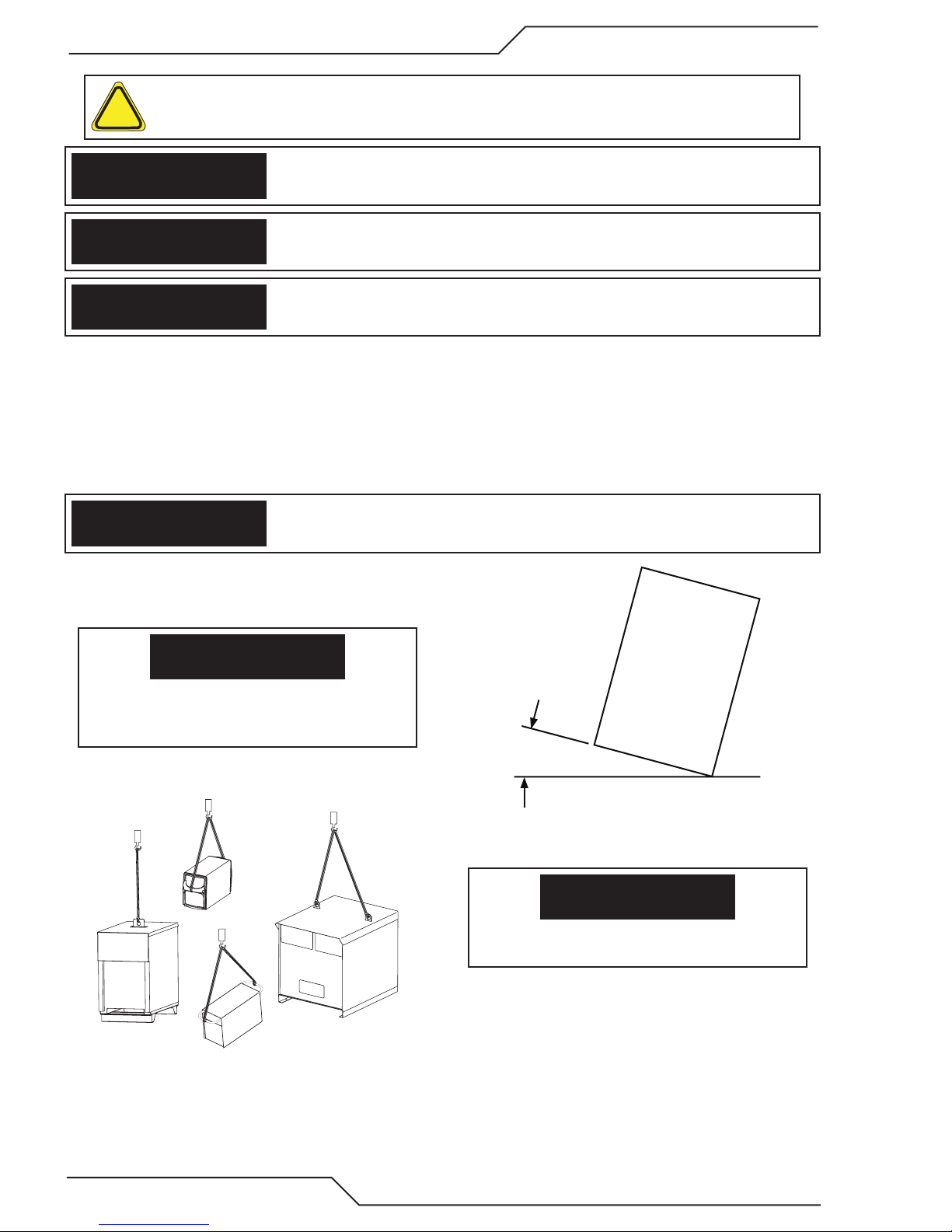
This product is solely intended for plasma cutting. Any other use may result in personal
injury and / or equipment damage.
If equipment is placed on a surface that slopes more
than 15°, toppling over may occur. Personal injury and
/ or signicant damage to equipment is possible.
15°
Art# A-12726
To avoid personal injury and/or equipment damage,
lift using method and attachment points shown here.
1-4 SAFETY INSTRUCTIONS Manual 0560956456
Art# A-12736
Page 13

iSERIES 100 /200 /300 /400
This Page Intentionally Blank
Manual 0560956456 SAFETY INSTRUCTIONS 1-5
Page 14
iSERIES 100 /200 /300 /400
1.02 Précautions de sécurité - FRENCH CANADIAN
AVERTISSEMENT : Ces règles de sécurité ont pour but d’assurer votre protection. Ils récapitulent les
informations de précaution provenant des références dans la section des Informations de sécurité sup-
!
plémentaires. Avant de procéder à l’installation ou d’utiliser l’unité, assurez-vous de lire et de suivre les
précautions de sécurité ci-dessous, dans les manuels, les fiches d’information sur la sécurité du matériel et sur
les étiquettes, etc. Tout défaut d’observer ces précautions de sécurité peut entraîner des blessures graves ou
mortelles.
PROTÉGEZ-VOUS -- Les processus de soudage, de coupage et de gougeage produisent un niveau
de bruit élevé et exige l’emploi d’une protection auditive. L’arc, tout comme le soleil, émet des rayons
ultraviolets en plus d’autre rayons qui peuvent causer des blessures à la peau et les yeux. Le métal
incandescent peut causer des brûlures. Une formation reliée à l’usage des processus et de l’équipement est essentielle pour prévenir les accidents. Par conséquent:
1. Portez des lunettes protectrices munies d’écrans latéraux lorsque vous êtes dans l’aire de travail, même
si vous devez porter un casque de soudeur, un écran facial ou des lunettes étanches.
2. Portez un écran facial muni de verres filtrants et de plaques protectrices appropriées afin de protéger vos
yeux, votre visage, votre cou et vos oreilles des étincelles et des rayons de l’arc lors d’une opération ou
lorsque vous observez une opération. Avertissez les personnes se trouvant à proximité de ne pas regarder
l’arc et de ne pas s’exposer aux rayons de l’arc électrique ou le métal incandescent.
3. Portez des gants ignifugiés à crispin, une chemise épaisse à manches longues, des pantalons sans
rebord et des chaussures montantes afin de vous protéger des rayons de l’arc, des étincelles et du métal
incandescent, en plus d’un casque de soudeur ou casquette pour protéger vos cheveux. Il est également
recommandé de porter un tablier ininflammable afin de vous protéger des étincelles et de la chaleur par
rayonnement.
4. Les étincelles et les projections de métal incandescent risquent de se loger dans les manches retroussées,
les rebords de pantalons ou les poches. Il est recommandé de garder boutonnés le col et les manches et
de porter des vêtements sans poches en avant.
5. Protégez toute personne se trouvant à proximité des étincelles et des rayons de l’arc à l’aide d’un rideau
ou d’une cloison ininflammable.
6. Portez des lunettes étanches par dessus vos lunettes de sécurité lors des opérations d’écaillage ou de
meulage du laitier. Les écailles de laitier incandescent peuvent être projetées à des distances considérables. Les personnes se trouvant à proximité doivent également porter des lunettes étanches par dessus
leur lunettes de sécurité.
INCENDIES ET EXPLOSIONS -- La chaleur provenant des flammes ou de l’arc peut provoquer un incendie. Le laitier incandescent ou les étincelles peuvent également provoquer un incendie ou une explosion.
Par conséquent :
1. Éloignez suffisamment tous les matériaux combustibles de l’aire de travail et recouvrez les matériaux avec
un revêtement protecteur ininflammable. Les matériaux combustibles incluent le bois, les vêtements, la
sciure, le gaz et les liquides combustibles, les solvants, les peintures et les revêtements, le papier, etc.
2. Les étincelles et les projections de métal incandescent peuvent tomber dans les fissures dans les planchers
ou dans les ouvertures des murs et déclencher un incendie couvant à l’étage inférieur Assurez-vous que
ces ouvertures sont bien protégées des étincelles et du métal incandescent.
3. N’exécutez pas de soudure, de coupe ou autre travail à chaud avant d’avoir complètement nettoyé la
surface de la pièce à traiter de façon à ce qu’il n’ait aucune substance présente qui pourrait produire des
vapeurs inflammables ou toxiques. N’exécutez pas de travail à chaud sur des contenants fermés car ces
derniers pourraient exploser.
4. Assurez-vous qu’un équipement d’extinction d’incendie est disponible et prêt à servir, tel qu’un tuyau
d’arrosage, un seau d’eau, un seau de sable ou un extincteur portatif. Assurez-vous d’être bien instruit
par rapport à l’usage de cet équipement.
1-6 SAFETY INSTRUCTIONS Manual 0560956456
Page 15

iSERIES 100 /200 /300 /400
5. Assurez-vous de ne pas excéder la capacité de l’équipement. Par exemple, un câble de soudage surchargé
peut surchauffer et provoquer un incendie.
6. Une fois les opérations terminées, inspectez l’aire de travail pour assurer qu’aucune étincelle ou projection de métal incandescent ne risque de provoquer un incendie ultérieurement. Employez des guetteurs
d’incendie au besoin.
7. Pour obtenir des informations supplémentaires, consultez le NFPA Standard 51B, “Fire Prevention in Use
of Cutting and Welding Processes”, disponible au National Fire Protection Association, Batterymarch
Park, Quincy, MA 02269.
CHOC ÉLECTRI QUE -- Le contact avec des pièces électriques ou les pièces de mise à la terre sous
tension peut causer des blessures graves ou mortelles. NE PAS utiliser un courant de soudage c.a. dans
un endroit humide, en espace restreint ou si un danger de chute se pose.
1. Assurez-vous que le châssis de la source d’alimentation est branché au système de mise à la terre de
l’alimentation d’entrée.
2. Branchez la pièce à traiter à une bonne mise de terre électrique.
3. Branchez le câble de masse à la pièce à traiter et assurez une bonne connexion afin d’éviter le risque de
choc électrique mortel.
4. Utilisez toujours un équipement correctement entretenu. Remplacez les câbles usés ou endommagés.
5. Veillez à garder votre environnement sec, incluant les vêtements, l’aire de travail, les câbles, le porteélectrode/torche et la source d’alimentation.
6. Assurez-vous que tout votre corps est bien isolé de la pièce à traiter et des pièces de la mise à la terre.
7. Si vous devez effectuer votre travail dans un espace restreint ou humide, ne tenez vous pas directement
sur le métal ou sur la terre; tenez-vous sur des planches sèches ou une plate-forme isolée et portez des
chaussures à semelles de caoutchouc.
8. Avant de mettre l’équipement sous tension, isolez vos mains avec des gants secs et sans trous.
9. Mettez l’équipement hors tension avant d’enlever vos gants.
10. Consultez ANSI/ASC Standard Z49.1 (listé à la page suivante) pour des recommandations spécifiques
concernant les procédures de mise à la terre. Ne pas confondre le câble de masse avec le câble de mise
à la terre.
CHAMPS ÉLECTRIQUES ET MAGNÉTIQUES — comportent un risque de danger. Le courant électrique
qui passe dans n’importe quel conducteur produit des champs électriques et magnétiques localisés.
Le soudage et le courant de coupage créent des champs électriques et magnétiques autour des câbles
de soudage et l’équipement. Par conséquent :
1. Un soudeur ayant un stimulateur cardiaque doit consulter son médecin avant d’entreprendre une opération
de soudage. Les champs électriques et magnétiques peuvent causer des ennuis pour certains stimulateurs
cardiaques.
2. L’exposition à des champs électriques et magnétiques peut avoir des effets néfastes inconnus pour la santé.
3. Les soudeurs doivent suivre les procédures suivantes pour minimiser l’exposition aux champs électriques
et magnétiques :
A. Acheminez l’électrode et les câbles de masse ensemble. Fixez-les à l’aide d’une bande adhésive lorsque
possible.
B. Ne jamais enrouler la torche ou le câble de masse autour de votre corps.
C. Ne jamais vous placer entre la torche et les câbles de masse. Acheminez tous les câbles sur le même
côté de votre corps.
D. Branchez le câble de masse à la pièce à traiter le plus près possible de la section à souder.
E. Veillez à garder la source d’alimentation pour le soudage et les câbles à une distance appropriée de
votre corps.
Manual 0560956456 SAFETY INSTRUCTIONS 1-7
Page 16

iSERIES 100 /200 /300 /400
LES VAPEURS ET LES GAZ -- peuvent causer un malaise ou des dommages corporels, plus particulièrement dans les espaces restreints. Ne respirez pas les vapeurs et les gaz. Le gaz de protection
risque de causer l’asphyxie.
Par conséquent :
1. Assurez en permanence une ventilation adéquate dans l’aire de travail en maintenant une ventilation
naturelle ou à l’aide de moyens mécanique. N’effectuez jamais de travaux de soudage, de coupage ou de
gougeage sur des matériaux tels que l’acier galvanisé, l’acier inoxydable, le cuivre, le zinc, le plomb, le
berylliym ou le cadmium en l’absence de moyens mécaniques de ventilation efficaces. Ne respirez pas
les vapeurs de ces matériaux.
2. N’effectuez jamais de travaux à proximité d’une opération de dégraissage ou de pulvérisation. Lorsque
la chaleur ou le rayonnement de l’arc entre en contact avec les vapeurs d’hydrocarbure chloré, ceci peut
déclencher la formation de phosgène ou d’autres gaz irritants, tous extrêmement toxiques.
3. Une irritation momentanée des yeux, du nez ou de la gorge au cours d’une opération indique que la ventilation n’est pas adéquate. Cessez votre travail afin de prendre les mesures nécessaires pour améliorer
la ventilation dans l’aire de travail. Ne poursuivez pas l’opération si le malaise persiste.
4. Consultez ANSI/ASC Standard Z49.1 (à la page suivante) pour des recommandations spécifiques concernant la ventilation.
5. AVERTISSEMENT : Ce produitcontient des produits chimiques, notamment du plomb, reconnu par l’Étatde la Californie pour causerdes malformations congénitaleset d’autresdommages touchant le système
reproductif.
MANIPULATION DES CYLINDRES -- La manipulation d’un cylindre, sans observer les précautions nécessaires, peut produire des fissures et un échappement dangereux des gaz. Une brisure soudaine du
cylindre, de la soupape ou du dispositif de surpression peut causer des blessures graves ou mortelles.
Par conséquent :
Se laver les mainsaprès manipulation.
1. Utilisez toujours le gaz prévu pour une opération et le détendeur approprié conçu pour utilisation sur
les cylindres de gaz comprimé. N’utilisez jamais d’adaptateur. Maintenez en bon état les tuyaux et les
raccords. Observez les instructions d’opération du fabricant pour assembler le détendeur sur un cylindre
de gaz comprimé.
2. Fixez les cylindres dans une position verticale, à l’aide d’une chaîne ou une sangle, sur un chariot manuel,
un châssis de roulement, un banc, un mur, une colonne ou un support convenable. Ne fixez jamais un
cylindre à un poste de travail ou toute autre dispositif faisant partie d’un circuit électrique.
3. Lorsque les cylindres ne servent pas, gardez les soupapes fermées. Si le détendeur n’est pas branché,
assurez-vous que le bouchon de protection de la soupape est bien en place. Fixez et déplacez les cylindres
à l’aide d’un chariot manuel approprié. Toujours manipuler les cylindres avec soin.
4. Placez les cylindres à une distance appropriée de toute source de chaleur, des étincelles et des flammes.
Ne jamais amorcer l’arc sur un cylindre.
5. Pour de l’information supplémentaire, consultez CGA Standard P-1, “Precautions for Safe Handling of
Compressed Gases in Cylinders”, mis à votre disposition par le Compressed Gas Association, 1235 Jefferson Davis Highway, Arlington, VA 22202.
ENTRETIEN DE L’ÉQUIPEMENT -- Un équipement entretenu de façon défectueuse ou inadéquate peut
causer des blessures graves ou mortelles. Par conséquent :
!
1. Efforcez-vous de toujours confier les tâches d’installation, de dépannage et d’entretien à un personnel
qualifié. N’effectuez aucune réparation électrique à moins d’être qualifié à cet effet.
2. Avant de procéder à une tâche d’entretien à l’intérieur de la source d’alimentation, débranchez l’alimentation électrique.
3. Maintenez les câbles, les fils de mise à la terre, les branchements, le cordon d’alimentation et la source
d’alimentation en bon état. N’utilisez jamais un équipement s’il présente une défectuosité quelconque.
1-8 SAFETY INSTRUCTIONS Manual 0560956456
Page 17

iSERIES 100 /200 /300 /400
DANGER
MISE EN GARDE
AVERTISSEMENT
MISE EN GARDE
4. N’utilisez pas l’équipement de façon abusive. Gardez l’équipement à l’écart de toute source de chaleur,
notamment des fours, de l’humidité, des flaques d’eau, de l’huile ou de la graisse, des atmosphères
corrosives et des intempéries.
5. Laissez en place tous les dispositifs de sécurité et tous les panneaux de la console et maintenez-les en
bon état.
6. Utilisez l’équipement conformément à son usage prévu et n’effectuez aucune modification.
INFORMATIONS SUPPLÉMENTAIRES RELATI VES À LA SÉCURITÉ -- Pour obtenir de l’information supplémentaire sur les règles de sécurité à observer pour l’équipement de soudage à l’arc électrique et le
!
coupage, demandez un exemplaire du livret “Precautions and Safe Practices for Arc Welding, Cutting and
Gouging”, Form 52-529.
Les publications suivantes sont également recommandées et mises à votre disposition par l’American Welding
Society, 550 N.W. LeJuene Road, Miami, FL 33126 :
1. ANSI/ASC Z49.1 - “Safety in Welding and Cutting”.
2. AWS C5.1 - “Recommended Practices for Plasma Arc Welding”.
3. AWS C5.2 - “Recommended Practices for Plasma Arc Cutting”.
4. AWS C5.3 - “Recommended Practices for Air Carbon Arc Gouging and Cutting”.
5. AWS C5.5 - “Recommended Practices for Gas Tungsten Arc Welding“.
6. AWS C5.6 - “Recommended Practices for Gas Metal Arc Welding”.
7. AWS SP - “Safe Practices” - Reprint, Welding Handbook.
8. ANSI/AWS F4.1, “Recommended Safe Practices for Welding and Cutting of Containers That Have Held
Hazardous Substances.”
9. CSA Standard - W117.2 = Safety in Welding, Cutting and Allied Processes.
SIGNIFICATION DES SYMBOLES - Ce symbole, utilisé partout dans ce manuel, signie “Attention” ! Soyez
!
vigilant ! Votre sécurité est en jeu.
Signie un danger immédiat. La situation peut entraîner des blessures graves ou mortelles.
Signie un danger potentiel qui peut entraîner des blessures graves ou mortelles.
Signie un danger qui peut entraîner des blessures corporelles mineures.
Classe de protection de l’enveloppe
L’indice de protection (codification IP) indique la classe de protection de l’enveloppe, c’est-à-dire, le degré de protection contre les corps solides étrangers ou l’eau. L’enveloppe protège contre le toucher, la pénétration d’objets
solides dont le diamètre dépasse 12 mm et contre l’eau pulvérisée à un angle de jusqu’à 60 degrés de la verticale.
Les équipements portant la marque IP21S peuvent être entreposés à l’extérieur, mais ne sont pas conçus pour
être utilisés à l’extérieur pendant une précipitation à moins d’être à l’abri.
Ce produit a été conçu pour la découpe au plasma seulement. Toute autre utilisation pourrait causer des blessures et/ou endommager l’appareil.
Manual 0560956456 SAFETY INSTRUCTIONS 1-9
Page 18

iSERIES 100 /200 /300 /400
MISE EN GARDE
MISE EN GARDE
L’équipement pourrait basculer s’il est placé sur une
surface dont la pente dépasse 15°. Vous pourriez
vous blesser ou endommager l’équipement de façon
importante.
15°
Art# A-12726
Soulevez à l’aide de la méthode et des points d’attache
illustrés an d’éviter de vous blesser ou d’endommager
l’équipement.
Art# A-12736
1-10 SAFETY INSTRUCTIONS Manual 0560956456
Page 19

iSERIES 100 /200 /300 /400
No
Yes
Ye s
Are Parts New
or Used?
Are Parts fully
assembled into
theTorch?
Unsure?
Disassembly fully
and re-assemble
theTorch Properly.
See Installation Manual.
ReplaceTorch Head
Is the Torch Damaged?
Replace Consumable
Cartridge and Shield Cup.
To rch still leaks?
Remove and Lubricate
all O-rings on Torch Head,
Consumables Cartridge,
and Consumables.
Re-assemble Torch.
Still leaks?
The parts probably are worn out.
See chart for approximate life expectancy.
The torch may be damaged. See page
to determine if head damage has occurred.
Order Coolant
Tube Replacement Kit
Leaking from
Coolant Supply or
Coolant Return?
Ye s
Yes
Yes
No
Return
Supply
Used
Order Coolant
CheckValve
Kit 9-4846
New
To rch leaks
Are Torch
Consumable Parts
Installed?
Art # A-09638
SECTION 2: TORCH MAINTENANCE
2.01 Coolant Leak Trouble-Shooting
Never operate the system if coolant leaks from the torch. A steady drip indicates that torch parts are damaged or installed improperly. Operating the system in this condition can damage the torch head. Refer to the following chart for guidance on coolant
leakage from the torch head.
Manual 0560956456 TORCH INFORMATION 2-1
Page 20

iSERIES 100 /200 /300 /400
Torch
Electrodes
Art # A-09653
Amperage Plasma Gas
O2 0.04 1
30
50
70
85 Air 0.08 2
100
150
200
250 O2 0.06 1.5
300
400
Air 0.04 1
N2 0.04 1
O2 0.04 1
Air 0.08 2
N2 0.04 1
O2 0.04 1
Air 0.08 2
N2 0.04 1
O2 0.04 1
H35 0.08 2
N2 0.08 2
O2 0.06 1.5
H35 0.08 2
N2 0.08 2
O2 0.06 1.5
H35 0.08 2
N2 0.08 2
O2 0.06 1.5
H35 0.08 2
N2 0.08 2
O2 0.08 2
H17 0.08 2
H35 0.08 2
N2 0.08 2
Recommended Wear
Depth for Electrode
Replacement
Inch mm
2-2 TORCH INFORMATION Manual 0560956456
Page 21

iSERIES 100 /200 /300 /400
Art # A-11512_AB
12
11
10
9
8
7
6
5
4
3
2
1
12
11
10
9
8
7
6
5
4
3
2
1
12
11
10
9
8
7
6
5
4
3
2
1
23X5560_AB
(-)
(+)
(+)
(+)
(+)
Remote
Plasma Marking
(-)
+
Corner Current
Reduction
(-)
(
-
)
(
-
)
(+)
(
-
)
(+)
(
-
)
(+)
(
-
)
Expanded
Metal
Spare #1 Output
Normally Open Contacts
Spare #2 Output
Normally Open Contacts
Hold Start
CNC Plasma Enable
(LV) OK To Move 2
Preflow On
Start/Stop Input
Pilot On Output
(Contacts)
Spare #2 Output
Normally Closed Contacts
Divided Arc Volts
Output
TB1
(LV) OK To Move 2
Stop (NC)
High +10V
Low (-)
10K
Analog Current Control
Wiper / Input
TB2
TB3
SW6
DC
(+)
OK To Move
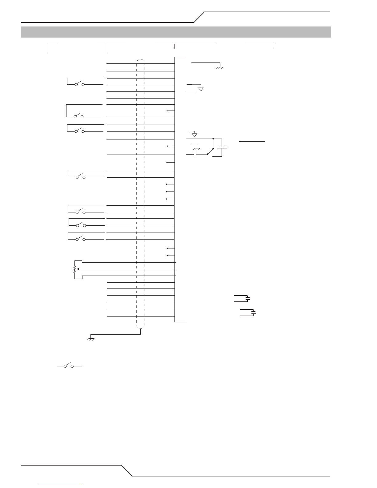
APPENDIX 1: CNC - Control Module PCB Connections
Manual 0560956456 APPENDIX A-1
Page 22

iSERIES 100 /200 /300 /400
APPENDIX 2: CNC
CNC functions
CNC I/O circuits provide at least 1000V galvanic isolation from the plasma power supply.
While the CNC circuits are isolated from the power supply, many of the signal returns on J15 and TB1, TB2 & TB3
are common to each other. J15 pins 1, 4, 5, 10, 17, and TB1-1, 5, 7, 9, and TB2-1 & 3 are all common. J15 pin 12 and
TB2-10 are also connected to the others when SW6 (OK to Move select) is set for voltage.
Rear Panel CNC Connector J15:
37 Circuit (Amp CPC) Remote Standard:
These are also duplicated on TB1, TB2 & TB3 use one or the other not both.
Chassis gnd (for SC-11 cable shield) 1
Start/Stop 3 (+); 4 (-)
Ok to Move (contacts or voltage 1) 12(-); 14 (+)
Divided Arc volts (selectable ratio
50:1; 40:1; 30:1; 16.6:1, 25:1) 5 (-); 6 (+)
PreFlow ON 7 (+); 9 (-)
Corner Current Reduction 10 (+); 11 (-)
Isolated Circuit Comm (for SC-11) 8
Chassis Gnd 13
Keying plug 15
Hold Start 16(+); 17 (-)
Plasma Mark 21 (+); 22 (-)
Cut Expanded Metal 23 (+); 24 (-)
CNC Plasma Enable2 25 (+); 26 (-)
Remote Analog Current Control 3 29 (+); 30 (signal); 31 (-)
Stop (Latched)
Pilot is ON (contacts) 34; 35
Spare (contact) 36; 37
SW4
32 (+); 33 (-)(comm.)
A-2 APPENDIX Manual 0560956456
Page 23

iSERIES 100 /200 /300 /400
Internal CNC connections. TB1, TB2 & TB3 on CCM module.
Connections are provided on the CCM module TB1, TB2 & TB3 terminal blocks including most of the rear panel
functions plus some additional features. All these signals are isolated from the plasma power supply but signals
marked (comm.) and (-) are common to each other.
Users are expected to install their own CNC cable to these connections. Knockout hole is provided in rear panel of
CCM module. User shall provide strain relief / cord grip for user installed cable.
TB1
Function Connection
CNC Enable/Disable TB1-2 (+), TB1-1(-)(comm.)
OK to Move 2 TB1-3 &TB1-12 Contacts only, rated 1A @ 28 VAC/DC
Stop Latched (NC) 4 TB1-4 (+) & TB1-5 (-) (comm.) used with Start Latched
Start/Stop Ret 4 TB1-6 (+), TB1-5 (-) (comm.)
or Start Latched (NO) 4 TB1-6 (+), TB1-5 (-) (comm.) used with Stop Latched
Divided Arc Voltage TB1-8 (+), TB1-7 (-) comm.
Remote Analog Current Control TB1-9 Analog Comm. (-) or 10K CC Pot low
TB1-10 Analog in (+) or CC Pot Wiper
TB1-11 10K CC Pot Hi (+10V @ 1 ma. Supply)
TB2
Function Connection
Hold Start TB2-2 (+),TB2-1 (-) (comm. )
Preflow ON TB2-4 (+), TB2-3 (-) (comm.)
Pilot is ON (contacts) TB2-6, TB2-8 rated 1A @ 120 VAC or 28 VDC
OK to Move (contacts or DC Volts)5 TB2-12 (+), TB2-10 (-)
TB3
Function Connection
Plasma Marking TB3-2(+), TB3-1(-) (comm.)
Corner Current Reduction TB-4(+), TB3-3(-)(comm.)
Cut Expanded Metal TB3-6(+), TB3-5(-)(comm.)
Spare NO Contact TB3-7, TB3-8
Spare NC Contact TB3-9, TB3-10
Spare NO Contact TB3-11, TB3-12
1
SW6 on CCM I/O PCB selects OK to Move for isolated contact closure or DC Volts (15-18V) at <100ma. When
set for contacts, OK to Move circuit is rated for 120 VAC / 28 VDC
2
Remove factory installed jumper from TB1-1 & 2 if using CNC Plasma Enable in J15.
3-5
See below.
Manual 0560956456 APPENDIX A-3
Page 24

iSERIES 100 /200 /300 /400
CNC Input / Output Descriptions
MOMENTARY START / STOP
START / STOP
TB1-6
TB1-5
TB1-4
SUSTAINED START / STOP
START
STOP
TB1-5
TB1-6
E-Stop input— Requires closed connection rated for 35ma. @ 20VDC for unit to operate. Factory installed jumper
between TB1-1&2 must be removing when connecting user supplied E-Stop circuit.
4
Start/Stop input—Switch (momentary or sustained) rating 35ma. @ 20 VDC
Start / Stop circuit congurations. Momentary Start / Stop (Latched) is only available at TB1.
Divided Arc Voltage output — Arc Voltage signal is isolated from plasma supply, however (-) is common with
other isolated CNC signals. Max Divided Arc Voltage signal level depends on actual arc voltage times divide ratio
however can not exceed approximately 12 V.
3
Analog Current Control input— Analog Current Control includes analog isolation module, separate isolation
module not usually required however it’s low input is common with the other isolated CNC inputs. Scaling of Analog
Current Control input is 0V = 0A, 10V. = MAX output and is linear in between. However MIN output is 5A. User
is responsible for setting correct analog voltage to maintain at least 5A output. To use Analog Current Control on
the I/O PCB set SW 11 to down position and on the CPU PCB set SW8-2 ON (up).
Hold Start input—Normally open, close to hold start. Circuit rating 10 ma. @ 20VDC. Delays pilot ignition, gas
preflow continues. Used by some height controls to flow gas while finding height. Also used for synchronizing starts
when multiple plasma supplies are used on same cutting table. User supplies circuit to keep Hold Start inputs active until all torches have found height. Used with CNC START. Apply START to begin gas flow. Same time apply
HOLD to delay ignition until height is found. Remove HOLD to ignite pilot, initiate arc transfer.
Preflow On input— Normally open, close to start preflow prior to normal START signal. Circuit rating 10 ma. @
20VDC. Torch Height Controls (THC) normally issue START signal to plasma supply after torch height has been
found. Then the plasma takes 1-2 seconds (or more) to perform preflow before igniting pilot. Some THCs have an
output that can start preflow early during height finding saving 1-2 seconds on each cut. PREFLOW ON should
remain active for at least 1 second after CNC START is applied. It is OK if it remains on until the end of the cut.
Need to recycle it to begin a new preflow prior to applying START for the next cut.
Pilot On output – Relay contacts rated 1A @ 120 VAC / 28 VDC. Contacts close when pilot on. Can be wired parallel
with Ok to Move contacts to start machine motion when pilot established. Used when starting over holes. Starting
over holes requires setting SW8-1 ON (up) on the CPU PCB for extended pilot time. Using extended pilot time to
start over holes or for cutting over holes will reduce parts life.
OK to Move output — Active when cutting arc is established, arc is transferred. Used to signal cutting table to
start X-Y motion. Relay contacts rated 1A @ 120 VAC or 28 VDC when SW6 set for contacts. When SW6 is set for
DCV, output supplies 15-18 VDC @ 100 ma. May be wired parallel with Pilot On to start cutting machine motion
as soon as pilot established.
A-4 APPENDIX Manual 0560956456
Page 25

iSERIES 100 /200 /300 /400
5
Ext. +10V
11
10
9
TB1
+10V
WIPER
Art # A-09246
OK to Move2 – Provides a second set of N.O. contacts that close when arc transfer is detected. Contacts are rated
for maximum of 24 VAC/DC @ 1A. Simplified CNC Circuit.
5
+10V @ 10ma. For Remote CC Pot – Previously CCM versions if one wanted to use a potentiometer for the Remote
Analog Current Control (CC) input an external 10 V supply was required for Pot High.. Now an isolated (from main
plasma circuits) 10V supply is provided. Recommended value of the pot is 5K or 10K.
5
Plasma Marking Select (Remote) – Plasma Marking, available only with Automatic Gas Control, may be activated with a contact closure between TB3-1 & TB3-2 if SW8-4, DIP switch on the CPU board (smaller of the 2 CCM
boards), is also on. Opening the connection between TB3-1 & TB3-2 switched back to normal cutting mode. For
ISeries power supplies It is OK to leave SW8-4 on whether you are marking or not.
The following functions may not yet be available on your system. *
*Corner Current Reduction (input)--- When activated, normally from a table controller’s corner or height control
inhibit signal, signaling that the cutting speed is being reduced to navigate a corner or small radius, the cutting
current is reduced at a fixed rate to a predetermined level to provide an improved cut at the lower speed.
*Cut Expanded Metal (input)---Normally the plasma supply is optimized for pierce cutting, high pierce height
directly above the metal to be cut, short pilot time, etc. Activating this input adjusts the plasma supply to optimize
it’s parameters for cutting expanded metal, perforated metal, running edge starting, etc. Among other changes
the transfer height is reduced to same as cut height. In addition to activating the Cut Expanded Metal input CCM
switch SW1-1 should be turned on automatically restart the pilot and SW8-1 set on for longer pilot time.
*Spare contacts --- Not currently activated. Planned for future CCM code release.
Manual 0560956456 APPENDIX A-5
Page 26

iSERIES 100 /200 /300 /400
Simplied CNC Circuit
15 - K ey Plug
J15-1 to chassis used for
SC-11 cable shield
AL L SW OFF f o r 5 0: 1 ( d e f au l t )
SW1 2A ( 1 ) ON = 1 6. 7 : 1 ( SC- 1 1)
SW1 2B ( 2 ) ON = 3 0: 1
SW1 2C ( 3 ) ON = 40 : 1
7 - K ey Pl ug
1 - 24 V AC
2 - 24 V AC Re t
8 - Tx +
12 - Tx -
13 - Rx +
14 - Rx -
9 - GND
10 - GN D
RS 485
/ 422
Comm
6- H MI P l asma En abl e SW
5- H MI P l asma En abl e SW
3- Jumper to 24 V AC
J15-13 connects SC-11
chassis to PS chassis.
The COMM Ref at pin
8 is also for the SC-11
Ult racut X T Si mplifi ed CN C
OK2 (cont act )
+10V (CC Pot Hi )
CC Pot W iper
CC Pot L ow
Di v Arc V (+)
Di v Arc V (-)
/Start - Stop (+)
/Start - Stop (-)
Stop Mo m NC
OK2 (cont act )
/ CNC Enabl e (+)
/ CNC Enabl e (-)
OK to M OV E (+)
OK to M OV E (-)
PILOT is ON
PILOT is ON
Prefl ow ON (+)
Prefl ow ON (-)
Hol d Start (+)
Hol d Start (-)
Spare #2 NO
Spare #2 NC
Spare #1b NO
/ Cut Expanded M etal (-)
/ Cut Expanded M etal (+)
/ Corner Current Red ucti on (-)
/ Corner Current Red ucti on (+)
/ Plasma M arki ng (-)
/ Plasma M arki ng (+)
Art # A-11579
TB 1
12
11
10
9
8
7
6
5
4
3
2
1
TB 2
12
11
10
9
8
7
6
5
4
3
2
1
TB 2
12
11
10
9
8
7
6
5
4
3
2
1
OK TO MOV E SELECT
18 V DC or Contacts
+18VDC
D C VO LT S
C ONT ACT S
SW6B
SW6A
PSR
OK
B
3
+
4
-
V OLT A GE DI VI DER
3 6
2 7
1 8
SW 12A
SW 12B
SW 12C
5
+10V
GND
4 5
SW 12D
A-6 APPENDIX Manual 0560956456
Page 27

iSERIES 100 /200 /300 /400
15 - K ey Plug
SPAR E #1a
J15-1 to chassis used for
SC-11 cable shield
7 - K ey Pl ug
1 - 24 V AC
2 - 24 V AC Re t
8 - Tx +
12 - Tx -
13 - Rx +
14 - Rx -
9 - GND
10 - GN D
RS 485
/ 422
Comm
6- H MI P l asma En abl e SW
5- H MI P l asma En abl e SW
3- Jumper to 24 V AC
J15-13 connects SC-11
chassis to PS chassis.
The COMM Ref at pin
8 is also for the SC-11
GND
J21
J22
J54 - Rem ote HM I & CN C CO M M
(100)
(101)
C hassi s
(102)
(109)
(108)
(1 15)
(116)
(117)
(1 18)
(119)
(120)
(133)
(134)
(135)
(136)
(137)
(138)
(139)
(140)
(141)
(142)
(143)
(144)
(145)
(146)
(147)
(148)
(149)
(150)
(151)
(132)
(152)
(153)
(154)
(155)
(156)
(157)
(158)
(159)
* Used with Mom en tary C NC St art SW
Harness to Relay PCB
Harness to CPU PCB
1
2
3
4
5
6
7
8
9
10
11
12
13
14
15
16
17
18
1
2
3
4
5
6
7
8
9
10
11
12
13
14
15
16
17
18
19
20
(142)
(133)
(134)
(137)
(139)
(138)
(143)
(140)
(141)
(136)
(135)
(132)
(153)
(144)
(145)
(146)
(147)
(148)
(149)
(150)
(151)
(152)
(154)
(155)
(156)
(157)
(158)
(159)
1
2
3
4
5
6
7
8
9
10
11
12
13
14
J15- CNC
1
2
3
4
5
6
7
8
9
10
11
12
13
14
15
16
17
18
19
20
21
22
23
24
25
26
27
28
29
30
31
32
33
34
35
36
37
3- / CNC Start (+)
4- / CNC Start (-)
5- D ivided A rc V (-)
6- D ivided A rc V (+)
7- / Pr eflow ON ( +)
8- COMM Ref (1K Ohm)
9- / Pr eflow ON ( -)
12- OK to M ove (-)
14- OK to M ove (+)
16- / H old Start (+)
17- / H old Start (- )
21- / Plasma M ark (+)
22- / Plasma M ark (-)
23- / Cut Expanded M etal (+)
24- / Cut Expanded M etal (-)
25- / CN C Plasma Enable (+)
26- / CN C Plasma Enable (-)
29- Remote CC Pot High
30- Remote CC ( analog)
31- Remote CC Pot Low
32- Stop SW (momentary) *
33- Stop SW Ret
34- Pilot is ON (a)
35- Pilot is ON (b)
e OU T #1 (a)
36- Spar
37- Spare OUT #1 (b)
Art # A-11579
Manual 0560956456 APPENDIX A-7
Page 28
iSERIES 100 /200 /300 /400
CNC Connections
Cutting Machine CNC Cable
(1)
*
2
( )
{
( )
3
( )
4
( )
5
( )
6
( )
7
( )
9
( )
10
( )
11
( )
12
( )
14
(16)
(17)
(21)
(22)
(23)
(24)
(25)
(26)
(29)
(30)
(31)
(32)
(33)
(34)
(35)
(36)
(37)
START/STOP
Start Motion
(OK-To-Move)
10 K
J15
10
11
12
13
14
15
16
17
18
19
20
21
22
23
24
25
27
28
29
30
31
32
33
34
35
36
37
26
Power Supply
1
*
2
NC
..........
3
4
5
..........
6
..........
7
8
..........
9
..........
*
..........
..........
..........
..........
..........
..........
..........
..........
..........
Source, 16 VDC, 10 ma.
...
Divided Arc V (-)
Divided Arc V (+)
Pre Flow ON (+)
Pre Flow ON (-)
Corner Current Reduction (+)
...
Corner Current Reduction (-)
OK-To-Move
DC
Relay DCV (-)
(+)
Contact or
SW6
/Hold Start(+)
/Hold Start(-)
/Plasma Mark (+)
/Plasma Mark (-)
/Cut Expanded Metal (+)
/Cut Expanded Metal (-)
/CNC Plasma Enable (+)
/CNC Plasma Enable (-)
Remote CC Pot High (+10VDC)
..........
Remote CC 0-10V Signal or Pot Wiper
..........
Remote CC Pot Low (-)
..........
Stop SW (momentary)
..........
Stop SW Ret
..........
Pilot is ON (a) Relay contact 1A @
..........
Pilot is ON (b)
..........
Spare OUT #1 (a)
..........
Spare OUT #1 (b)
(1A @ DCV (+)
120 VAC ( 15 - 18 VDC @
or 28 VDC) up to 100 ma.)
120 VAC or 28
Shield
**
Represents switch,
relay, open
collector transistor, etc.
A-8 APPENDIX Manual 0560956456
* Power Supply Gnd not used for CNC cable
Do not connect wire #1 to anything.
** Cable Shield drain wire must be
connected to ground at cutting machine.
Art # A-11901
Page 29

iSERIES 100 /200 /300 /400
APPENDIX 3: GSC Control PCB Layout
J1
J9
TP6
J5
J6
SW2
J8
TP5
J2
TP3
TP2
TP4
J3
J4
SW1
TP7
TP1
Art # A-09188_AC
LED
D1
D-17
LED
D_E1
D_E15
D21
D22
Manual 0560956456 APPENDIX A-9
Page 30

iSERIES 100 /200 /300 /400
APPENDIX 4: DPC Control PCB Layout
TP6
J5
J6
SW2
TP5
TP3
TP2
TP4
SW1
TP8
TP1
Art # A-09189_AB
J1
J2
J3
J4
J9
J8
TP7
TP9
TP10
TP11
J10
D7
D12
D11
D10
D5
D4
D3
D2
D1
D9
D8
D6
A-10 APPENDIX Manual 0560956456
Page 31

iSERIES 100 /200 /300 /400
APPENDIX 5: GSC / DPC Power Supply PCB Layout
F2
J2
D7
D6
TP1
TP6 D5
D9
TP7
D16
TP8
J1
F1
TP4
TP5
TP2
TP3
Art # A-09597_AB
Manual 0560956456 APPENDIX A-11
Page 32

iSERIES 100 /200 /300 /400
= Test Point
= Test Point
APPENDIX 6: CCM CPU PCB Layout
A-12 APPENDIX Manual 0560956456
Art # A-11675_AC
Page 33

iSERIES 100 /200 /300 /400
CCM CPU PCB
Test Points
TP1 GND
TP2 ISO +5.0V
TP3 +24V
TP4 +3.3V
TP5 ISO GND
TP6 +5.0V
TP7 TOTAL DEMAND 3.3V=400A
TP9 /WR
TP10 /RD
TP11 CPU TEMP SENSE
TP12 +3.3VA
TP13 -15VDAC
TP14 PC2
TP15 +15VDAC
TP16 CLKO
TP18 OSC_CLOCK
LED Reference
D2 Red RXD
D3 Red TXD
D4 Red Fiber Out 2
D7 Red Fiber Out 1
D11 Green Future Use
D17 Green Future Use
Manual 0560956456 APPENDIX A-13
Page 34

iSERIES 100 /200 /300 /400
APPENDIX 7: CCM I/O PCB Layout
= Test Point
Art # A-11676_AD
A-14 APPENDIX Manual 0560956456
Page 35

iSERIES 100 /200 /300 /400
CCM I/O PCB
Test Points
TP1 GND
TP2 /COOLANT FANS ON
TP3 /TORCH PUMP ON
TP4 LOW COOLANT FLOW (SW)
TP5 COOLANT FLOW SIGNAL (PULSE)
TP6 +15V ISOLATED
TP7 -15V ISOLATED
TP8 +18V ISOLATED
TP9 ANALOG CURRENT CONTROL 0-3.3V
TP10 GND ISOLATED
TP11 /PILOT ENABLE
TP12 +5VDC
TP13 -15VDC
TP14 +15VDC
J Connectors
J21 BASIC CNC
J22 EXTENDED CNC
J23 RELAY - INTERFACE BOARD
J24 ARC / TIP VOLTS
J25 TEST
J26 GAS BOX
J28 TO CPU
J29 TO CPU
TP15 24VDC
TP18 +5V ISOLATED
TP19 WORK CURRENT
LED Reference
D2 Green PLASMA ENABLE
D3 Green E-STOP_PS
D4 Green GAS ON
D6 Green CNC START
D8 Green HOLD START
D12 Green PREFLOW ON
D13 Green CSD
D18 Green MARK
D20 Green SPARE1
D25 Green EXP METAL
D33 Green OK TO MOVE
D37 Green PSR
D41 Green SPARE FIELD OUT 2
D43 Green SPARE FIELD OUT 1
Manual 0560956456 APPENDIX A-15
Page 36

iSERIES 100 /200 /300 /400
= Test Point
= Test Point
APPENDIX 8: Pilot PCB Layout
A-16 APPENDIX Manual 0560956456
Art # A-11677_AB
Page 37

iSERIES 100 /200 /300 /400
Pilot PCB Test Points
TP1 GND
TP2 PILOT GATE
TP3 +5V
TP4 TIP
LED Reference
D2 Green PILOT ENABLE
D11 Green +5V
Manual 0560956456 APPENDIX A-17
Page 38

iSERIES 100 /200 /300 /400
APPENDIX 9: Relay and Interface PCB Layout
= Test Point
A-18 APPENDIX Manual 0560956456
Page 39

iSERIES 100 /200 /300 /400
Relay and Interface PCB Test Points
TP1 GND
TP2 -15V
TP3 +5VDC
TP4 +12V
TP5 +24V
TP6 +15V
TP7 +5VDC
LED Reference
D2 Green 1 TORCH GAS ON
D7 Green PILOT ENABLE
D11 Green PILOT CURRENT DETECTED
D12 Green WORK CURRENT DETECTED
D22 Green CONTACTORS ON
D23 Green RF ON
D24 Green FANS ON
D25 Green PLASMA ENABLED
D26 Green 1 TORCH ON
D27 Green TORCH COOLANT ON
Manual 0560956456 APPENDIX A-19
Page 40

iSERIES 100 /200 /300 /400
APPENDIX 10: Display PCB Layout
= Test Point
= Test Point
A-20 APPENDIX Manual 0560956456
Art # A-11679
Page 41

iSERIES 100 /200 /300 /400
Display PCB Test Points
TP1 GND
TP2 +5VDC
TP3 +24VDC
Manual 0560956456 APPENDIX A-21
Page 42

iSERIES 100 /200 /300 /400
APPENDIX 11: System Bias PCB Layout
= Test Point
= Test Point
A-22 APPENDIX Manual 0560956456
Art # A-11680_AB
Page 43

iSERIES 100 /200 /300 /400
System Bias PCB Test Points
TP1 GND
TP2 24VDC
TP3 DC INPUT POSITIVE
TP4 Vcc1
TP5 Vcc2
TP6 GATE
TP7 PRIMARY GND
TP8 +12V PRIMARY
TP9 P_ISOL_GND
TP10 DC SENSE POSITIVE
LED Reference
D3 Red MISSING PHASE
D4 Red AC V HIGH
D14 Red AC V LOW
D15 Green VAC_IDA
D26 Green +12V PRIMARY
D27 Green VAC_IDB
D30 Green 24VDC
D44 Green TRANSFORMER ON
Manual 0560956456 APPENDIX A-23
Page 44

iSERIES 100 /200 /300 /400
APPENDIX 12: Main Inverter Bottom PCB Layout
= Test Point
Art # A-11681_AC
= Test Point
A-24 APPENDIX Manual 0560956456
Page 45

iSERIES 100 /200 /300 /400
Main Inverter Bottom PCB Test Points
TP1 GND
TP2 GATE 2A
TP3 GATE 1A
TP4 GATE 3A
TP5 GATE 4A
TP6 GATE 2B
TP7 GATE 1B
TP8 GATE 4B
TP9 GATE 3B
TP10 +12VP
TP11 +12VDC
TP12 THERMISTOR SIDE A
TP13 THERMISTOR SIDE B
TP14 +5VDC
TP15 PGND
LED Reference
D3 Red CAP IMBALANCE
D4 Green READY
Manual 0560956456 APPENDIX A-25
Page 46

iSERIES 100 /200 /300 /400
APPENDIX 13: Main Inverter Top PCB Layout
= Test Point
Art # A-11682_AC
= Test Point
A-26 APPENDIX Manual 0560956456
Page 47

iSERIES 100 /200 /300 /400
Main Inverter Top PCB Test Points
TP1 GND
TP2 GATE 2A
TP3 GATE 1A
TP4 GATE 3A
TP5 GATE 4A
TP6 GATE 2B
TP7 GATE 1B
TP8 GATE 4B
TP9 GATE 3B
TP10 +12VP
TP11 +12VDC
TP12 THERMISTOR SIDE A
TP13 THERMISTOR SIDE B
TP14 +5VDC
TP15 PGND
LED Reference
D3 Red CAP IMBALANCE
D4 Green READY
Manual 0560956456 APPENDIX A-27
Page 48

iSERIES 100 /200 /300 /400
APPENDIX 14: Control and Fault PCB Layout
= Test Point
Art # A-11683_AC
= Test Point
A-28 APPENDIX Manual 0560956456
Page 49

iSERIES 100 /200 /300 /400
Control and Fault PCB Test Points
TP1 GND
TP22 +12VDC
TP23 +5VDC
TP24 GATE 1+
TP25 A_OUT1
TP26 B_OUT1
TP27 GATE 1-
TP28 I_SNS1
TP29 GATE 2+
TP30 I_DMD1 0.5V-6.7V
TP31 GATE 2-
TP32 -12VDC
TP33 START 2
TP34 SHDN
TP35 ENABLE
TP36 READY IN
TP37 READY OUT
LED Reference
D1 Red INV FLT
D14 Red OVER TEMP
D24 Green PWM ON
D32 Red PRI OC
Manual 0560956456 APPENDIX A-29
Page 50

iSERIES 100 /200 /300 /400
APPENDIX 15: Cap Bias Bottom PCB Layout
A-30 APPENDIX Manual 0560956456
Art # A-11685_AC
Page 51

iSERIES 100 /200 /300 /400
APPENDIX 16: Cap Bias Top PCB Layout
Manual 0560956456 APPENDIX A-31
Art # A-11686_AC
Page 52

iSERIES 100 /200 /300 /400
APPENDIX 17: Suppressor PCB Layout
A-32 APPENDIX Manual 0560956456
Art # A-11684_AC
Page 53

iSERIES 100 /200 /300 /400
APPENDIX 18: COOLING DIAGRAM
Over Flow
HE400
**FOR 400 AMP
SYSTEMS
REV DESCRIPTION DATE APPROVED
iSERIES XT POWER SUPPLIES
100A-400A
AA ECO B2502 8-8-2013 AJR
RAS 1000
XT-300
Filter 1
Torch Coolant
Return
Torch Coolant
Supply
Cold Plate 3
Radiator
Bubble
Sensor
Flow Switch
Coolant
Return
Cold Plate 1
Cold Plate 2
Level Switch
Coolant tank
Flow
Supply
Flow
HS1 Temp
Sensor
Pump
Manual 0560956456 APPENDIX A-33
Art # A-13072
Page 54

iSERIES 100 /200 /300 /400
APPENDIX 19: Remote Arc Starter Schematic
1
A A
B B
PLASMA
POWER
SUPPLY
GND
NEG
J59-RAS
1
2
3
4
5
6
7
8
9
10
11
12
13
14
PILOT
C C
WORK
2
Jumper in cable
to ID Arc Starter
is connected.
Chassis gnd
120 VAC
120 VAC RET
J58
10
11
12
13
14
15
16
1
2
3
4
5
6
7
8
9
RAS
1000 XT
NEG
GND
PILOT
GND
(99)
(98)
CGND
3
4
5
6
IGNITION UNIT SIG 4.5
115 Vac
NEG
0.047 uf
100K
0.047 uf
115 Vac RET
PLT
(49)
RAS Capacitor PCB
Neon
0.1 uf
PU
L1
(52)
HbHo
Torch Shield
Brass Ring
(-)
TORCH
(+)
Electrode
Tip
Work
GND
(+)
Rev
AA ECO B2487 RWH 07/30/2013
D D
Revision
1
By
2
A-34 APPENDIX Manual 0560956456
Date
The information contained herein is proprietary to Victor Technologies.
Not for release, reproduction or distribution without written consent.
Title
SCHEMATIC
RAS 1000 XT Arc Starter
3
4
Art # A-13073
Victor Technologies Headquarters
16052 Swingley Ridge Road, Suite 300
St Louis, Missouri 63017 USA
Date Printed
Drawn
Size
Drawing Number
7/30/2013
DAT
A
Date Revised
Date
03/13/2013
Sheet
1 1
042X1361
5
7/30/2013
of
6
Page 55

iSERIES 100 /200 /300 /400
This Page Intentionally Blank
Manual 0560956456 APPENDIX A-35
Page 56

iSERIES 100 /200 /300 /400
APPENDIX 20: Schematic, DFC Auto Gas Box System
Art # A-13074
1
1
2
2
3
3
A
B
C C
D D
(S15T)
(S14B)
(S14T)
(S13T)
(S12B)
(S12T)
(S11T)
(S10B)
(S10T)
(S9-B)
(S9-T)
(S8-B)
(S8-T)
(S7-B)
(S7-T)
(S6-B)
(S6-T)
(S5-B)
(S5-T)
(S4-T)
(S3-T)
(S2-T)
(S1-T)
(S1-B)
(S2-B)
(S3-B)
(S4-B)
(S11B)
(S13B)
(S14B)
(2a)120VAC DMC RET
GRN
BLK
(1)120VAC DMC
(JMP)
(3)
(8)
(9)
(2b)
E_STOP NO
E_STOP COM
(8)
(9)
+5V
(PW3)
(2c)
(2c)
-12V
(PW1)
GND
+12V
(PW4)
+24V SW
(PW5)
+24V FUSED
(PW6)
GND
SHIELD
Rx-
Rx+
Tx- (B)
SIG COM
SIG COM
Tx+ (A)
COM
PLASMA ENABLE
HMI PRESENT
24 VAC RET
24 VAC
RED
)5()5(
)6()6(
120VAC DMC
E_STOP COM
E_STOP NO
120VAC DMC RET(2a)
WHT
(5)
(5)
(6)
(6)
)9()9(
(8)
Tx+ (A)
(12)
Tx- (B)
(12)
(1)
(2)
)3()3(
(8)
)01()01(
(1)
(2)
(20V)
(20V)
(0V)
(0V)
(1)
(3)
(PW2)
(PW8)
(PW7)
SHIELD
+24 VDC
+5 VDC
+15 VDC
15 VDC RET
120 VAC ULTRACUT
120 VAC ULTRACUT RET
24 VAC RET
24 VAC
PLASMA ENABLE +
PLASMA ENABLE -
SHIELD
24 VAC
24 VAC RET
PLASMA ENABLE
KEY PLUG
Tx+ (A)
Tx- (B)
Rx+
Rx-
+5 VDC
Data +
Data -
COM
Shield
CHASSIS GND
FUEL_PLASMA
H35_PLASMA
O2_PLASMA
O2_SHIELD
AIR_PREFLOW
AIR_PLASMA
AIR_SHIELD
AIR_MARKING
N2_PREFLOW
N2_PLASMA
N2_SHIELD
O2_PREFLOW
N2_MARKING
H20_SHIELD
ARGON_MARKING
DMC3000 - MANIFOLD CONTROLLER ASSEMBLY
19X2367
FERRITE
CORE
ULTRACUT POWER SUPPLY
MANIFOLD
PANEL INDICATORS
GROUNDING SCREW
CCM
DMC FiberOptic Ports
19X2385
DMC3000 CONTROL PCB
DMC3000 Control PCB LEDs
SOLENOID DRIVE ON INDICATOR (GREEN LEDs)
D1 - SOL_V1 (H35 PLASMA))
D2 - SOL_V2 (O2_PLASMA)
D3 - SOL_V3 (AIR_PLASMA)
D4 - SOL_V4 (N2 PLSMA)
D5 - SOL_V5 (AUX PLASMA)
D6 - SOL_V6 (O2 SHIELD)
D7 - SOL_V7 (AIR_SHIELD)
D8 - SOL_V8 (N2 SHIELD)
D9 - SOL_V9 (H2O SHIELD)
D10 - SOL_V10 (O2 PREFLOW)
D11 - SOL_V11 (AIR PREFLOW)
D12 - SOL_V12 (N2 PREFLOW)
D13 - SOL_V13 (ARGON MARKING)
D14 - SOL_V14 (AIR MARKING)
D15 - SOL_V15 (N2 MARKING)
D16 - (SPARE)
D17 - +5VDC
SOLENOID FAULT INDICATOR (RED LEDs)
D_E1 - SOL_V1 FLAG (H35_PLASMA)
D_E2 - SOL_V2 FLAG (O2_PLASMA)
D_E3 - SOL_V3 FLAG (AIR_PLASMA)
D_E4 - SOL_V4 FLAG (N2_PLASMA)
D_E5 - SOL_V5 FLAG (AUX_PLASMA)
D_E6 - SOL_V6 FLAG (O2_SHIELD)
D_E7 - SOL_V7 FLAG (AIR_SHIELD)
D_E8 - SOL_V8 FLAG (N2_SHIELD)
D_E9 - SOL_V9 FLAG (H2O_SHIELD)
D_E10 - SOL_V10 FLAG (O2_PREFLOW)
D_E11 - SOL_V11 FLAG (AIR_PREFLOW)
D_E12 - SOL_V12 FLAG (N2_PREFLOW)
D_E13 - SOL_V13 FLAG (ARGON_MARKING)
D_E14 - SOL_V14 FLAG (AIR_MARKING)
D_E15 - SOL_V15 FLAG (N2_MARKING)
19X2384 SMPS +24; +/-12; +5
755x000
CONTROL
CABLE
CHASSIS GND
UNIT E-STOP
SHIELD
120 VAC
120 VAC RET
FERRITE
CORE
OPTION SWITCHES
PLASMA ENABLE
BYPASS RELAY
I/O PCB
CPU PCB
I
CPU PCB
JUMPER
for 2 WIRE
(RS485 only)
wire to A & B
SERIAL
COMMUNICATION
(Isolated)
JUMPER
for 4 WIRE
uses
TX+, TXRX+, RX-
4W 2W
J14
J14
SW14 - LINE
TERMINATION
normally on
(refer to manual)
0
5
9
8
7
6
1
2
3
4
SW10-ADDRESS
normally 0
(refer to
manual)
POWER SUPPLY
24 VAC to 20 VDC
ISOLATED
HMI INTERFACE PCB
19X2407
KEY
RS232
Configured
for RS485
TPC- 660E TOUCH SCREEN PANEL
J63 HARNESS NOT INSTALLED
(for future use with Height Control)
GROUNDING SCREW
TSC 3000 19X2200
HMI CONTROL &
COMMUNICATIONS
4W 2W
SW14
NOTE:
DMC solenoids are 18 VDC.
Coils are about 46 ohms.
24 VDC is applied for 1 second
then reduced by pulse width
modulation to an average of
approximately 7-8 VDC.
KEY PLUG
TEST POINTS - CONTROL PCB
TP1 - GND
TP2 - Processor TEMP
TP3 - +VREF
TP4 - Processor CLKO
TP5 - +3.3V
TP6 - AGND
TP7 - +5V
TEST POINTS - INTERFACE PCB
TP1 - GND
TP2 - UNREG VDC
TP3 - +5VDC
TP4 - +20 VDC
LEDS - INTERFACE PCB:
D1 = RX (RS 485)
D14 = RX (RS 232)
D15 = TX (RS 232)
Power Supply PCB (19X2384) LEDS
See list by DPC 3000 Power Supply
CCM CANBUS
ACTIVE
DPC CANBUS
ACTIVE
Tx Gray;
Rx Black
D2 = SLAVE SUPPLY
CAN BUS ACTIVE
D3 = GCM CAN BUS ACTIVE
D11 = INITIALIZING /
PROGRAMMING
D12 = STATUS CODE
D13 = +5VDC
D17 = RS485 TXD
D18 = RS485 RXD
CPU LEDS
J65
USB
J65
USB
1
2
3
4
5
6
SW2-4SW2-4
STATUS LED (RED)STATUS LED (RED)
SOL8SOL8
J62
THC (future)
J62
THC (future)
1
2
3
4
5
6
7
8
9
10
11
12
13
14
SOL4SOL4
E-STOPE-STOP
SOL14SOL14
J56J56
1
2
3
4
5
6
7
8
9
10
11
12
13
14
15
16
17
18
19
20
21
22
23
24
25
26
27
28
29
30
31
32
33
34
35
36
37
U7/U9
FiberOptic
U7/U9
FiberOptic
1
2
U4 / U7
SLAVE FiberOptic
U4 / U7
SLAVE FiberOptic
1
2
J21
MANIFOLD ID
J21
MANIFOLD ID
1
2
3
P8
SOL DRIVE A
P8
SOL DRIVE A
1
2
3
4
5
6
7
8
9
10
11
12
13
14
15
16
17
18
19
20
SOL12SOL12
SW2-3SW2-3
J3
TX/RXJ3TX/RX
1
2
J54J54
1
2
3
4
5
6
7
8
9
10
11
12
13
14
SOL3SOL3
COM1COM1
123456789
P5
HW IDP5HW ID
1
2
3
P1P1
1234567
8109
P5P5
1234567
8109
J6
JTAGJ6JTAG
1
2
3
4
5
6
7
8
9
10
11
12
13
14
J57J57
1
2
3
4
5
6
7
8
9
10
11
12
13
14
SOL10SOL10
F2
3A SBF23A SB
P7
POWERP7POWER
1234567
8
D21D21
SOL11SOL11
SW1-3SW1-3
P61P61
1
2
3
4
5
6
7
8
9
10
11
12
13
14
15
16
P1P1
1
2
3
4
5
6
7
8
E-STOPE-STOP
SW2-2SW2-2
SOL2SOL2
SOL13SOL13
COM2COM2
123456789
SW1-1SW1-1
P4
RS 485P4RS 485
1
2
3
4
5
6
SOL7SOL7
SW1
PLASMA ENABLE
SW1
PLASMA ENABLE
P55P55
1
2
3
4
5
6
7
8
9
10
11
12
13
14
15
16
17
18
19
20
21
22
23
24
25
26
27
28
29
30
31
32
33
34
35
36
37
SW2-1SW2-1
SOL1SOL1
U4/U5
FiberOptic
U4/U5
FiberOptic
1
2
P54
HMI Serial/Control
P54
HMI Serial/Control
1
2
3
4
5
6
7
8
9
10
11
12
13
14
P2P2
1
2
3
4
5
6
7
8
POWER LED (GREEN)POWER LED (GREEN)
SOL9SOL9
SOL6SOL6
J55J55
1
2
3
4
5
6
7
8
9
10
11
12
13
14
15
16
17
18
19
20
21
22
23
24
25
26
27
28
29
30
31
32
33
34
35
36
37
D22D22
F1
1.6A SBF11.6A SB
SOL15SOL15
P2
RS 485P2RS 485
1
2
3
4
5
6
P56P56
1
2
3
4
5
6
7
8
9
10
11
12
13
14
15
16
17
18
19
20
21
22
23
24
25
26
27
28
29
30
31
32
33
34
35
36
37
J1J1
1
2
3
4
U10 / U13
GAS FiberOptic
U10 / U13
GAS FiberOptic
1
2
J63J63
1
2
3
4
5
6
7
8
9
E-STOPE-STOP
SW1-4SW1-4
SOL5SOL5
J2
RS232 ProgJ2RS232 Prog
1
2
3
4
5
6
7
8
9
P3
POWERP3POWER
1
2
3
4
5
6
E1E1
P10
HMI POWER
P10
HMI POWER
GND-+
SW1-2SW1-2
J61J61
1
2
3
4
5
6
7
8
9
10
11
12
13
14
15
16
P4
SOL DRIVE B
P4
SOL DRIVE B
1
2
3
4
5
6
7
8
9
10
11
12
13
14
15
16
17
18
P57P57
1
2
3
4
5
6
7
8
9
10
11
12
13
14
A-36 APPENDIX Manual 0560956456
Page 57

iSERIES 100 /200 /300 /400
Art # A-13074
4
4
5
5
6
6
A
B
BLK
PURPLE
ORANGE
BLK
PURPLE
ORANGE
BLK
PURPLE
ORANGE
BLK
PURPLE
ORANGE
BLK
PURPLE
BLK
PURPLE
ORANGE
BLACK/SHIELD
WHITE
RED
ORANGE
(WHT)
(WHT)
(BLK)
(WHT)
(S2-B)
120 VAC
)1()1(
(2a)
120 VAC RET
(2a)
(9)
E_STOP COM (9)
(8)
E_STOP NO
(S2-B)
(V5-1)
(V5-2)
(V1-1)
(V1-2)
(V2-1)
(V2-2)
(V3-1)
(V3-2)
(S1-T)
(S1-B)
(V4-1)
(V4-B)
-12VDC(PW1)
GND(PW2)
+5VDC(PW3)
+24 VDC_FUSED(PW6)
(S3-B)
+12VDC(PW4)
E-STOP(PW8)
+24VDC SW(PW5)
GND(PW7)
(S3-T)
(8)
+24 VDC
+5V
+12V
DWG No:
Sheet
of
SupersedesScale
Date:Drawn:
References
DateByRevisionsRev
PCB No:
Assy No:
Information Proprietary to THERMAL DYNAMICS CORPORATION.
Not For Release, Reproduction, or Distribution without Written Consent.
NOTE: UNLESS OTHERWISE SPECIFIED -
1. RESISTOR VALUES ARE EXPRESSED IN OHMS, 1/4W 5%.
2. CAPACITOR VALUES ARE EXPRESSED IN MICROFARADS (uF).
Chk: App:
TITLE:
Last Modified:
Size
SCHEMATIC,
THERMAL DYNAMICS
INDUSTRIAL PARK #2
WEST LEBANON, NH 03784
(603) 298-5711
42X1292
Monday, April 19, 2010
1 1
Friday, December 08, 2006
14:00:59
DPC3000 CONTROL PCB
DFC 3000 SYSTEM SCHEMATIC
DPC3000 - PRESSURE CONTROL ASSEMBLY
PANEL INDICATORS
GROUNDING SCREW
19X2382
19X2383
PLASMA_VENT
PLASMA_MARK
MANIFOLD (partial)
MANIFOLD (partial)
FERRITE
CORE
GROUNDING SCREW
NOTE:
1: DO NOT DAISY CHAIN GROUNDS. USE A SEPARATE GROUND
CONDUCTOR FOR EACH ASSEMBLY TO STAR GND.
2: KEEP GROUNDS AS SHORT AS POSSIBLE.
3: USE #4 OR GREATER SIZE CABLE FOR GROUNDING
4: MAKE SURE ASSEMBLIES ARE SECURED PROPERLY BEFORE USE
5: ALL COVERS MUST BE FULLY INSTALLED BEFORE USE.
OPTION SWITCHES
LEDs Listed Below
DPC FiberOptic Port
DPC3000 Control PCB LEDs
D1 - PLASMA_PWM
D2 - PLASMA_VENT_PWM
D3 - SHIELD_H20_PWM
D4 - SHIELD_GAS_PWM
D5 - MARKING_PWM
D6 - PLASMA_PILOT_PWM
D7 - +5VDC
D8 - DPC STATUS
D9 - SHIELD_H20_FLOW
D10 - PLASMA_CUT_PWM
D11 - PLASMA_LOW_PWM
D12 - CANBUS COMMUNICATION
MANAFOLD ID
SOL1
SOL2
V1
V2
V3
V4
PRE-FLOW >
MARKING >
PLASMA >
GAS SHIELD >
H2O SHIELD >
SHIELD OUT
PLASMA OUT
VENT
19X2384 SMPS +24; +/-12; +5
120 VAC
120 VAC RET
DPC MANIFOLD
PLASMA_CUTTING
SOL3
FERRITE
CORE
Plasma_Cut_Hi
DAT
N/A
4/24/2009
SOL# = ON/OFF CONTROL VALVE
V# = PROPORTIONAL VALVE
PS# = PRESSURE SENSOR
FS# = FLOW SENSOR (LIQUID)
Proportional valves V1-V5
powered by up to 24 VDC
Actual average voltage is
proportional to the amount
valve opening.
Coil resistance (cold):
V1 = 23 ohms;
V2= 59 ohms;
V3 & 4 = 42 ohms
V5 = 55 ohms.
NOTE:
DPC SOL solenoids are 18 VDC.
Coils are about 46 ohms.
24 VDC is applied for about 0.1
second then reduced by pulse
width modulation to an average
of approximately 9-10 VDC.
KEY PLUG
TEST POINTS - CONTROL PCB
TP1 - GND
TP2 - FLOW (H2O Shield)
TP3 - +5V
TP4 - +VREF
TP5 - +24V Fused
TP6 - +3.3VA
TP7 - 3.3V
TP8 - +12V
TP9 - Processor CLKO
TP10 - Processor TEMP
TP11 - -12V
SOL#
H35 >
O2 >
AUX >
H2O >
AIR >
ARGON >
N2 >
DMC MANIFOLD
1
> GAS SHIELD
2
3
4
5
6
7 8
9
10
11
> H2O SHIELD
> PREFLOW
12
13 14
15
> MARKING
> PLASMA
INLET PASSAGES
OUTLET PASSAGES
HOSE
AA ECO-B1391 DAT
4-24-2009
D5 = +VDC Fused (24VDC )
D6 = +12VDC
D7 = +24VDC SW (24VDC to Valves
& Solenoids through E-Stop Relay
D9 = +5VDC
D16 = -12VDC
Power Supply PCB (19X2384) LEDS
Tx Gray;
Rx Black
DPC CANBUS
ACTIVE
AB
ECO-B1507 - added text
DAT
4-19-2010
SW2-2SW2-2
PS3PS3
J60J60
1
2
3
4
5
6
7
8
9
10
11
12
13
14
15
16
PS3
Plas_Pilot_P-in
PS3
Plas_Pilot_P-in
1
2
3
P1P1
1
2
3
4
5
6
7
8
PS5PS5
F3 1.6A SBF3 1.6A SB
FS-1
H2O_Shield_FlowSensor
FS-1
H2O_Shield_FlowSensor
1
2
3
PS6PS6
PS2
Shield_Water_P-in
PS2
Shield_Water_P-in
1
2
3
SW2-1SW2-1
V4
Plasma_Cut_Lo
V4
Plasma_Cut_Lo
1
2
3
J5
PROG via RS232
J5
PROG via RS232
1
2
3
4
5
6
7
8
9
PS6
Plasma_P-out
PS6
Plasma_P-out
1
2
3
SW1-4SW1-4
P2-WFSP2-WFS
1
2
3
P2P2
1
2
3
4
5
6
7
8
J10
JTAG
J10
JTAG
1
2
3
4
5
6
7
8
9
10
11
12
13
14
E-STOPE-STOP
E-STOPE-STOP
D12D12
J8
TX/RXJ8TX/RX
1
2
STATUS LED (RED)STATUS LED (RED)
E-STOPE-STOP
SW1-3SW1-3
SOL3SOL3
U1/U2
FiberOptic
U1/U2
FiberOptic
1
2
PS5
Shield_Gas_P-out
PS5
Shield_Gas_P-out
1
2
3
P9P9
1
2
3
4
5
6
7
8
F4 3A SBF4 3A SB
SW2-4SW2-4
V5V5
1
2
3
SW1-2SW1-2
P4
STATUS LEDS
P4
STATUS LEDS
1
2
3
4
SOL1SOL1
V1
SHIELDV1SHIELD
1
2
3
P6
ValvesP6Valves
1
2
3
4
5
6
7
8
9
10
11
12
13
14
15
16
P1
Press_sensors
P1
Press_sensors
1
2
3
4
5
6
7
8
9
10
11
12
13
14
15
16
17
18
PS4
Plasma_Cut/Mark_P-in
PS4
Plasma_Cut/Mark_P-in
1
2
3
SW2-3SW2-3
V2
SHIELD_H2O
V2
SHIELD_H2O
1
2
3
J23J23
1
2
3
P60P60
1
2
3
4
5
6
7
8
9
10
11
12
13
14
15
16
PS1
Shield_Gas_P-in
PS1
Shield_Gas_P-in
1
2
3
PS4PS4
SW1-1SW1-1
V3
Plasma_PILOT
V3
Plasma_PILOT
1
2
3
SOL2SOL2
PS1PS1
POWER LED (GRN)POWER LED (GRN)
P3 - HWIDP3 - HWID
1
2
3
PS2PS2
Manual 0560956456 APPENDIX A-37
Page 58

iSERIES 100 /200 /300 /400
APPENDIX 21: System Schematic 100A, 380-415V PG 1
5
b
p
N
p
A
380-415
VAC
INPUT
(Customer
supplied
ower cord
B
must pass
through
ferrite core
assembly.)
L1
1
L2
1
L3
1
Earth
1
CHASSIS GND
C
18 AWG wire
oth in and out of
CB1
D
CB1
ON / OFF
16 A
8A, 500V, SB
E
J63 = Mini-Fit Jr goes to
J12 on T1 primary
400 VAC -- Single 18 AWG
in pins 1 & 12
480 VAC -- Single 18 AWG
in pins 1 & 12
230 VAC -- 18 AWG
wires in pins
F
1, 6, 7, 12
Art # A-13075
1
EMI
FIL-
1
TER
2
PCB
IN1
OUT1
1
2
IN2
OUT2
1
GND2B
2
IN3
(1)
(2)
OUT3
CHASSIS GND
(3)
(3-22)
(1-20)
(2-21)
(26)
(28)
(27A&B)
F2
F1
8A, 500V, SB
AC INPUT
(86A)
1
2
3
4
(27A)
5
6
7
8
(85A)
9
(86B)
10
11
12
13
(27B)
14
15
16
17
(85B)
18
J60
J63
(43A)
1
2
(3-22)
(1-20)
(2-21)
AC
SUPPRESSION
PCB
J51
019X504000
1
2
3
4
PANEL AC INDICATOR
J52
1
2
3
4
GND
INTERNAL AC INDICATOR
LT1 & LT2
INPUT POWER
Rear Panel & Internal
+24VDC
+ V
GND
12
W1A
EON INDICATORS
480V-ID
4
(20)
2
1
(21)
2
1
(22)
2
1
J50
1
2
3
(1)
4
5
6
7
(2)
8
9
10
11
12
13
(3)
14
AC LINE
CHASSIS GND
SYSTEM BIAS SUPPLY PCB
019X501900
1234567891011
TO AUX TRANSFORMER
(44A)
LEDS
D3, RED, MISSING PHASE
TO J12
T1 PRIMARY
(Sht 2, A1)
2
D4, RED, AC V HIGH
D14, RED, AC V LOW
D26, GREEN, +12V PRI
D30, GREEN, 24VDC
D44, GREEN, T1 ON
3
(7)
W1B
W1C
(8)
(9)
Toriod Core
(7)
(8)
(9)
Toriod Core
(10)
LT1
(11)
(12)
LT2
(13)
To J27 on CCM I/O PCB
J62
1
2
3
4
5
6
7
8
9
10
11
12
13
14
208-230V-ID
COM
400V-ID
J61
123
VOLTAGE SELECTION
Wire #48 from J61-1 to:
J61-2 for 208-230 VAC
(48)
J61-3 for 400 VAC
J61-4 for 480 VAC
System Bias LEDs & Test Points
(Sht 2, E3)
24 VDC
24 VDC
MISSING PHASE a
MISSING PHASE b
AC V HIGH a
AC V HIGH b
AC V LOW a
24 VDC_RET
24 VDC_RET
AC V LOW b
VAC_IDA a
/ VAC_IDA b
VAC_IDB a
/ VAC_IDB b
230V 400V 480V ERR
/VAC_IDAb 0 1 0 1
/VAC_IDBb 0 0 1 1
Measure relative to TP1 (24VDC_RET)
"0" = 10-12V "1" = 24V
TEST POINTS
TP1 SECONDARY GND
TP2 24VDC
TP3 DC INPUT POSITIVE
TP4 VCC1
TP5 VCC2
TP6 GATE
TP7 PRIMARY GND
TP8 +12V PRIMARY
TP9 P ISOL GND
3
L5
L4
4
J105B AC INPUT
1
2
J104B
1
2
J103B
1
2
J105A
1
2
J104A
1
2
J103A
1
2
INVERTER MODULE (IM) #`1 (bottom)
MAIN PCB LEDS
D3, RED, CAP
IMBALANCE
D4, GREEN, READY
CAP BIAS PCB LEDS
D6, GREEN, -12V
D11, GREEN, +12VP
019x502700
D13, GREEN, +12V
AC INPUT
019x502000
Component Locations (not including PCB components)
C4 Capacitor, fan starting, 8uf 440VAC (Sht 2, E1)
CB1 Circuit Breaker /ON/OFF SW, 15A 480V
(Sht 1, E1)
CB2-4 Circuit Breaker, 5A, 250V (Sht 2, B3)
F1, 2 Fuse, 8A, 500V, S.B. (Sht 1,E1)
FAN1,2 Fan, Heat Exchanger , 230 VAC (Sht 2, D2)
FL1 Flow meter, pulse output (Sht 2, B2)
FS1 Flow SW, 0.5 GPM (3.8 lpm), N.O. (Sht 2, A2)
HCT1 Current Sensor, Hall Eect 200A, Work Lead
(Sht 1, C8)
K1 Relay, 24VAC, Inrush Control, (Sht2, B9)
L1 Inductor, (Sht 1, B7)
L3-5 Toriod Co
(29)
LS1 Level Switch, Coolant Tank (Sht 2, A3)
(30)
LT1, LT2 Indicator, Neon, 250V, AC Volts Present
(31)
(Sht 1, B2 & C2)
(32)
M1 Motor, Pump, ½ hp 230VAC, 50/60 Hz, 1Ph
(33)
(Sht 2, C2)
(34)
MC1 Relay, 120VAC, Inrush, coil (Sht2, B9)
(35)
contact (Sht2, A1)
(36)
(37)
MC2 Relay, 120 VAC, Fan Control, coil
(38)
(Coil at Sht 2, A7)(Contacts at Sht 2, D1)
(39)
MC3 Relay, 120 VAC, Pump Motor Control, coil
(40)
(41)
(42)
(Coil at Sht 2, A7)(Contacts at Sht 2, C1)
R2 Inrush, 4.7 Ohm, 30W (Sht2, A1)
R3,4 Ext RC, 100 ohm 55W (Sht1, A7)
SA1-3 Snubber, Contactor & Relay coils
(Sht 2, A8 & A9)
T1 Aux Transformer (Sht 2, B2)
TB4 Terminal Block (Sht 1, C9)
TS1 Temperature Sensor, NTC, Coolant Return
(Sht 2, A5)
TS2 Temperature Sensor, NTC, Ambient (Sht 2, A5)
W1 Contactor , Input (Coil Sht 2, A8), (Contacts C2)
re Common Mode Ind (Sht1 B8, B&C3)
4
5
IM #1 Section B (upper)
CONTROL PCB LEDS
D1, RED, INV FLT
D14, RED, OVER TEMP
D24, GREEN, PWM ON
D32, RED, PRI OC
IM #1 Section A (lower)
WORK (+)
A-38 APPENDIX Manual 0560956456
Page 59

iSERIES 100 /200 /300 /400
6
p
7
8
9
10
J100 -- 30 CKT RIBBON
ELECTRODE (-)
WORK (+)
OUTPUT
J100 -- 30 CKT RIBBON
ELECTRODE (-)
WORK (+)
OUTPUT
PILOT BOARD
LED'S
D2 PILOT ENABLE
D11 +5V
R3 & R4
(51B)
(50)
(50)
2
J46-M
2
J46-F
1
1
To J24 on I-O PCB
TO CCM
CPU PCB
J32
(Sht 2, C3)
J102B
(49B)
5
4
3
2
1
TO CCM
CPU PCB
J31
(Sht 2, C3)
J102A
(49A)
5
4
3
2
1
TO J1 on RELAY PCB
(Sht 2, B9)
RIBBON CABLE 30 ckt.
CCM (J31& 32) - INVERTER (J100)
1 READY +
2 READY 3 INVERTER_FLT +
4 INVERTER_FLT 5 OVERTEMP_FLT +
6 OVERTEMP_FLT 7 PWR_PRESENT +
8 PWR_PRESENT 9 OUT_COM (+3 to 5VDC)
10 VAC_SELA
11 VAC_SELB
12 IS_IDA
13 IS_IDB
14 IS_IDC
15 ENABLE +
16 ENABLE 17 START2 +
18 START2 19 SPARE
20 SYNC_IN +
21 SYNC_IN 22 NC
23 NC
24 47 OHM to COMM
25 DEMAND +
26 DEMAND 27 47 OHM to COMM
28 CURRENT +
29 CURRENT 30 47 OHM to COMM
TEST POINTS
TP1 GND
TP2 PILOT GATE
TP3 +5V
J58A
J58C
5
4
3
2
1
019X501600
J40
INVERTER
123456789
J42
L1
TO J3 on RELAY PCB
10 ckt Ribbon
(Sht 2, A5)
(Sht 2, D3)
(51)
(51)
J16
(56)
o
(57)
b
(58)
g
(59)
w
RIBBON CABLE 40 ckt CCM (J23) - RELAY PCB (J4)
1 COMMON
2 /1TORCH START *
3 NA
4 /1TORCH GAS SOL ON *
5 /MAIN TORCH IDLE *
6 /1TORCH PRESS OK *
7 FLOW SENSOR (pulses)
8 LOW COOLANT FLOW
9 COOLANT LEVEL OK
10 COMMON
11 NA
12 /PLASMA ENABLE-HMI
13 /COOLANT PUMP ON
14 COMMON
15 /PILOT ENABLE
16 /RAS ON
17 /CONTACTORS ON
18 COMMON
19 /COOLANT FANS ON
20 /1TORCH CONTACTOR ON *
21 /PLASMA ENABLE RELAY
22 COMMON
23 PILOT CURRENT SIG24 NC
25 PILOT CURRENT SIG+
26 COMMON
27 WORK CURRENT SIG28 WORK CURRENT SIG+
29 NC
30 AMBIENT TEMP
31 COOLANT TEMP
* Used with 1 Torch O
J43
ELECTRODE
TIP VOLTS
WORK
ARC VOLTS
HCT1
Hall Eect Sensor
123
123
+15 VDC
-15 VDC
(49)
1
PILOT PCB
10
(53)
4
4
SIG (+)
COMMON
1234567
(51)
(55)
tion
TORCH
To TB4-7
J44
1
CHASSIS GND
J41
1
2
TIP
J45
8
(52)
To TB4-6
J41 (J87)
To / From Optional
1 Torch Module
(Refer to 1 Torch
section for details.)
(51)
TORCH
(Sht 1, A9)
TIP
(Sht 1, A9)
AC 120V- TB4-4
AC 120V- Ret- TB4-3
AC 24V-TB4-2
AC 24V- Ret -TB4-1
(J10 Sht 2, B8)
32 COMMON
33 -15 VDC
34 COMMON
35 24 VDC
36 COMMON
37 24 VDC
38 COMMON
39 24 VDC
40 COMMON
RIBBON CABLE 16 ckt
CCM ( J37) - DISPLAY
PCB (J17)
1,3,5,7 24 VDC
2,4,6,8 COMMON
9,10 NC
11-16 SERIAL DATA
RIBBON CABLE 10 ckt
RELAY PCB (J3) – PILOT PCB (J42)
1,2 24 VDC
3,4,7,10 COMMON
5 PILOT ENABLE +
6 PILOT ENABLE –
8 PILOT CURRENT SIG –
9 PILOT CURRENT SIG +
TIP
1
2
(49)
(52)
(51)
(60)
(61)
(62)
(63)
(49)
L3
(52)
(51)
TB4
ARC VOLTS (TORCH)
7
TIP VOLTS (PILOT)
6
WORK
5
4
120 VAC @ 100 ma.
3
2
24 VAC @ 1A
1
TORCH
PILOT
CHASSIS GND
WORK
1
RAS
1
A
SHIELD
(-)
(+)
Electrode
Tip
1
Work
B
(+)
C
D
E
Art # A-13075
Revision
Rev
00 Initial Design DAT 10 /03/2012
5
6
Date
By
4102/61/9TADAA
DAT 10/17/2014AB ECO-B2687
Revision
Rev
7
Date
By
The information contained herein is proprietary to Thermal Dynamics.
Not for release, reproduction or distribution without written consent.
Title
Ultra-Cut XT 100A CE 380-415 VAC
8
10
SCHEMATIC
9
2800 Airport Rd.
Denton, Texas 76207 USA
Date Printed
12/16/2014
Drawn
DAT
Size
C
Drawing Number
042X1354
Date Revised
Date
10/03/2012
Sheet
1 2
F
11/20/2014
of
Manual 0560956456 APPENDIX A-39
Page 60

iSERIES 100 /200 /300 /400
APPENDIX 22: System Schematic 100A, 380-415V PG 2
p
1
J12 = Mini-Fit Jr
400 VAC -- Single 18 AWG in pins 1 & 4
480 VAC -- Single 18 AWG in pins 1 & 8
230 VAC -- 18 AWG wires in pins 1,5,2,6
From Sys Bias J63
Mini-Fit Jr
1 234
5 678
(Sht 1, F2)
(43A) (44A)
R2
4.7 30W
1234567
J12
A
B
Mini-Fit
J13
C
D
J13 to CB5
and to MC2
& MC3, also
J14, J16
all 18 AWG
4
(64A)
(64B)
(65A)
230 VAC
(64A)
Alternate fan.
100 & 200A units may use either this
single larger fan (same as 300 & 400A
units) or the 2 smaller fans shown above.
J72
1
E
2
3
MC1A
(87)
8
460V
400V
220V
0 V
123
MC3A
(65B)
MC3B
(64B)
MC2A
(65A)
MC2B
RRBK
C4
BN
T1
CHASSIS GND
FAN1
(66)
(67)
(69)
(70)
(69)
(70)
CHASSIS GND
BL
24V RET
24V
120V_2 RET
120V_2
120V-1 RET
2
FS1
COOLANT
0.7 GPM
FL1
r
1
b
2
g
3
BLUE
RED
YELLOW
BLUE
RED
YELLOW
120V_1
J16
1
2
3
Torch Coolant Pump
(69)
J72
1
2
3
J73
1
2
3
(70)
M1
230 VAC _ SW _ RET
(A9)
FAN1
FAN2
230 VAC _ SW
(A9)
Harness from System Bias PCB J62
(Sht 1, E3)
. 230V 400V 480V ERR
J62-12 (/VAC_IDAb) 0 1 0 1
J62-14 (/VAC_IDBb) 0 0 1 1
Measure relative to TP1 (24VDC_RET)
"0" = 10-12V "1" = 24V
3
LS1
COOLANT LEVEL
J74
1
2
6
5
4
3
2
1
J14
Harness from Pilot PCB J45
230 VAC_SW
goes to J70
for HE 400
24 VDC
24 VDC
MISSING PHASE a
MISSING PHASE b
AC V HIGH a
AC V HIGH b
AC V LOW a
24 VDC_RET
24 VDC_RET
AC V LOW b
VAC_IDA a
/ VAC_IDA b
VAC_IDB a
/ VAC_IDB b
1
2
3
4
J49
(77) (78)
CB2 5 A
(74) (75)
CB3 5 A
(71) (72)
CB4 5 A
To J100 of IM #1B
To J100 of IM #1A
(Sht 1, B&C- 5&6)
WORK
ARC VOLTS
(55)
(84)
(83)
(80)
(81)
(82)
(79)
(Sht 1, B8)
TIP VOLTS
(51)
(29)
(30)
(31)
(32)
(33)
(34)
(35)
(36)
(37)
(38)
(39)
(40)
(41)
(42)
(76)
(73)
AMBIENT
(Sht 1, C8)
(57)
(56)
TS2
5
COOLANT
TS1
(93)(92)
4
1
(90)
2
(89)
3
4
J71
TO HCT1 (Work)
(58)
(59)
(94)
(95)
12345
6
J2
TEMP SENSOR
Test Points
TP1, GND
TP2, -15V
TP3, +5VDC
TP4, +12V
TP5, +24V
TP6, +15V
TP7, +5VDC
1 TORCH INTERFACE
Refer to 1 Torch Module Schematic for Details
123456789
J84
12345
J85
1011121314
J11
CPU PCB (CCM )
123
J5
+5VDC
SIGNAL (pulse)
120VAC_2
24VAC
120VAC_1
BIAS TRANSFORMER
LEVEL SENSORS
COOLANT FLOW SW
1
2
3
4
TORCH FLOW SENSOR
J6
12
11
10
9
8
7
6
5
4
3
2
1
J9
J31 - 30 CKT RIBBON J32 - 30 CKT RIBBON
J1
WORK CURRENT SENSOR
RELAY & INTERFACE PCB
D2, GREEN, 1TORCH GAS ON
D7, GREEN, PILOT ENABLED
D11, GREEN, PILOT CURRENT
D12, GREEN, WORK CURRENT
D22, GREEN, CONTACTORS ON
D23, GREEN, RF ON
D24, GREEN, FANS ON
D25, GREEN, PLASMA ENABLED
D26, GREEN, 1TORCH ON
D27, GREEN, COOLANT ON
019X501700
1234567
8
1
2
J7
N/C
J33 - 30 CKT RIBBON J34 - 30 CKT RIBBON
COMMON
4
N/C
+15 VDC
-15 VDC
SIG (+)
123
N/CN/C
J35 - 30 CKT RIBBON J36 - 30 CKT RIBBON
19X501100
I-O PCB (CCM)
I / O PCB LEDS
---------------------------------------------D2 CNC PLASMA ENABLE
D3 E-STOP_PS
(53)
1
2
3
4
5
6
7
8
J24
1
2
3
4
5
6
7
8
9
10
11
12
13
14
J27
D4 GAS ON (Auto-cut, PAK)
D6 CNC START
D8 HOLD START
D12 PREFLOW ON
D13 CSD (corner current reduction)
D18 MARK
D20 SPARE
D25 EXP METAL
D33 OK_CNC
D37 PSR
D41 SPARE OUT 2
D43 SPARE OUT 1
I / O PCB TEST POINTS
------------------------------------TP1 PCB COMMON
COOLANT FANS ON
TP2
TP3 PUMP ON
TP4 LOW FLOW (SW)
TP5 FLOW SIGNAL (pulse, Ultracut only)
TP6 +15VDC_ISO (ref to TP10)
TP7 -15VDC_ISO (ref to TP10)
TP8 +16-18 VDC_ISO (ref to TP10)
TP9 ANALOG CURRENT SIGNAL
TP10 ISOLATED VOLTAGE COMMON
TP11 1 TORCH CONTACTOR ON
TP12 +5 VDC
TP13 -15 VDC
TP14 +15 VDC
TP15 +24 VDC
TP18 +5 VDC_ISO (ref to TP10)
I / O PCB DIP SW
--------------------------------------------SW6 OK TO MOVE
(CONTACTS, VOLTS)
SW11 ANALOG CC SOURCE
SW12 DIVIDED ARC VOLTAGE
(50:1, 16.7:1, 30:1, 40:1, 25:1)
19X501200
J28 30 CKT RECEPTACLE - BOTTOM ENTRY
J28 30 CKT PIN HEADER
(remote & Autocut only)
F
Art # A-13076
1
2
A-40 APPENDIX Manual 0560956456
3
4
Page 61

iSERIES 100 /200 /300 /400
6
TO PILOT PCB
(Sht 1, B8)
10 CKT RIBBON
(160)
ARC_SUPPRESSOR
(162)
ARC_SUPPRESSOR
PILOT A SIG Vin+
PILOT A SIG Vin-
/ PILOT ENABLE
/ PILOT ENABLE RET
10
J3
PILOT PCB
123456789
J8
CONTROL OUTPUTS
24 VDC
GND
J4 -- 40 CKT RIBBON CABLE
J38
123456789
RS 232 D-SUB
SERIAL PROG
PORT
1
2
3
4
5
6
J18
J29 30 CKT RECEPTACLE - BOTTOM ENTRY
J29 30 CKT PIN HEADER
CPU PCB LEDs
---------------------------D2 RXD (red)
D3 TXD (red)
D4 CAN BUS (slave)
D7 CAN BUS (MAIN)
D11 5 VDC POWER
D17 STATUS CODE
D18 INITIALIZING /
PROGRAMMING (red)
CPU PCB TEST POINTS
-------------------------------------------PCB common)
TP1 GND (
TP2 +5V_ISO (REF TP5)
TP3 +24 VDC
TP4 +3.3V
TP5 GND_ISO
TP6 +5.0 V
TP7 TOTAL DEMAND
(3.3V = 400A)
TP9 /WR
TP10 /RD
TP11 CPU TEMP SENSE
TP12 +3.3VA
TP13 -15VDAC
TP14 PC2
TP15 +15VDAC
TP16 CLKO
TP18 OSC_CLOCK
CPU PCB DIP SW
---------------------------------------------
SW1 AUTO PILOT RESTART
SW3 PREFLOW TIME
SW4 POSTFLOW TIME
SW5 FUNCTION
SW8 SYSTEM CONTROL
(pilot time, etc.)
SW9 RESERVED (future)
SW10 ADDRESS (default = 0)
SW13 UNIT TYPE (AC / UC)
SW14 LINE TERMINATION
(serial comm.)
Rev
5
Revision
00 Initial Design DAT 10/03/2012
6
PROG
USB IC
By
DAT 10/17/2014AB ECO-B2687
1
2
3
4
5
6
7
8
9
10
11
12
J19
/ Plasma Marking (-)
/ Plasma Marking (+)
Date
7
MC2
Fan Control
SA3
(161)
MC3
SA4
(163)
10111213141516
NORMAL PROGRAM
J23- 40 ckt ribbon cable
TB1
OK2 (contact)
12
+10V (CC Pot Hi)
11
CC Pot Wiper
10
CC Pot Low
Div Arc V (+)
Div Arc V (-)
/Start - Stop (+)
/Start - Stop (-)
Stop Mom NC
OK2 (contact)
/ CNC Enable (+)
/ CNC Enable (-)
OK to MOVE (+)
OK to MOVE (-)
PILOT is ON
PILOT is ON
Preflow ON (+)
Preflow ON (-)
Hold Start (+)
Hold Start (-)
Spare
Digital
Inputs
Spare #1b NO
Spare
Digital
Inputs
Rev
4102/61/9TADAA
9
8
7
6
5
4
3
2
1
TB2
12
11
10
9
8
7
6
5
4
3
2
1
TB3
12
11
10
9
8
7
6
5
4
3
2
1
7
Pump Motor Control
(96)
(98)
(99)
(97)
123456789
120 VAC_124 VAC
120 VAC_2
HMI/GCM
J10
USB Cable to Front Panel
J39
123
4
USB
PORT
1
2
3
4
5
6
7
8
9
10
11
12
J20
ENABLE
PLAS_ENABLE SW
PLAS_ EN_SW_RET
OK
+10V
GND
PSR
SPARE #1a
Revision
SA1
(100)
18
(101)
17
(102)
16
(103)
15
(104)
14
13
12
(106)
11
10
(108)
9
(109)
8
(110)
7
(111)
6
5
4
3
(113)
2
(61)
1
2 WIRE 4 WIRE
GAS ON
/ GAS PRESS OK
/ BASIC ID
GND
By
(96)
ARC_SUPPRESSOR
AC 24V GCM2
AC 120V - GCM
AC 24V - RET - GCM2
AC 120V- Ret- GCM
AC 120V- Ret- TB4-3
GND
GND
RxTx+
Rx+
Tx-
J30
J26
GND
J21
J22
Date
8
230 VAC to HE 400
(70)
230 VAC _ SW
(D2)
230 VAC _ SW _ RET
(D2)
230 VAC Ret
W1
(97)
120 VAC to RAS
MC1
(60)
(62)
(60)
(63)
(62)
1
2
(63)
3
4
J47
(116)
1
(117)
J37
2
3
4
5
6
1
2
3
4
5
6
7
8
9
10
11
12
13
14
15
16
1
2
3
4
5
6
7
8
9
10
11
12
13
14
15
16
17
18
1
2
3
4
5
6
7
8
9
10
11
12
13
14
15
16
17
18
19
20
Harness
(120)
(115)
(119)
(118)
16 CKT RIBBON
(130)
(112)
(114)
(121)
(122)
(124)
(129)
(128)
(123)
(125)
(126)
(127)
(142)
(133)
(134)
(137)
(139)
(138)
(143)
(140)
(141)
(136)
(135)
(132)
(153)
(144)
(145)
(146)
(147)
(148)
(149)
(150)
(151)
(152)
(154)
(155)
(156)
(157)
(158)
(159)
The information contained herein is proprietary to Thermal Dynamics.
Not for release, reproduction or distribution without written consent.
Title
Ultra-Cut XT 100A CE 380-415 VAC
8
120VAC
AC 24V GCM1
AC 24V-TB4-2
AC 120V- TB4-4
AC 24V Ret- GCM1
AC 24V- Ret -TB4-1
K1
1
5
INRUSH CONTROL
SCHEMATIC
(107)
2
(107)
4
(61)
3
AC 24V Ret - GCM1
AC 24V Ret-GCM2
AC 120V - GCM
AC 120V- Ret- GCM
Art # A-13076
9
CHASSIS GND
120 VAC Ret
Harness
AC 24V-GCM1
AC 24V-GCM2
J69
2
1
9
J70 - HE
(70)
)96()96(
J59 - RAS
(99)
(98)
J54 - Remote HMI & CNC COMM
(100)
(101)
(102)
(109)
(108)
(115)
(116)
(117)
(118)
(119)
(120)
Display PCB
J17
019X501800
J55 - GCM
(121)
(122)
(123)
(124)
(125)
(126)
(127)
(128)
(129)
(130)
(131)
(112)
(114)(131)
(103)
(110)
(104)
(111)
(166)
(167)
(106)
(113)
CHASSIS GND
J15-CNC
(133)
(134)
(135)
(136)
(137)
(138)
(139)
(140)
(141)
(142)
(143)
(144)
(145)
(146)
(147)
(148)
(149)
(150)
(151)
(132)
(152)
(153)
(154)
(155)
(156)
(157)
(158)
(159)
* Used with Momentary CNC Start SW
Thermal Dynamics Corporation
Date Printed
Drawn
Size
Drawing Number
10
1
2
3
4
5
6
7
1
2
3
3 - Key Plug
4
5
6
7
8
9
10
11
12
13
14
1
1 - 24 VAC
2
2 - 24 VAC Ret
3
3- Jumper to 24 VAC
4
5
5-HMI Plasma Enable SW
6
6-HMI Plasma Enable SW
7
7 - Key Plug
8
8 - Tx+
RS 485
9
9 - GND
/ 422
10
10 - GND
Comm
11
12
12 - Tx-
13
13 - Rx+
14
14 - Rx-
1- PLAS_ENABLE SW *
1
2- PLAS_ EN_SW_RET
2
3- GAS PRESS OK RET
3
4- / GAS PRESS OK
4
5- POT HIGH (GCM 1000)
5
6- POT WIPER (GCM 1000)
6
7- POT LOW (GCM 1000)
7
8- BASIC ID RET
8
9- / BASIC ID **
9
10-
10
11-
11
GCM 1000 XT
12
Jumper
13
14-
14
15- 24 VAC - RET
15
16
17
* Plasma Enable SW
18
in GCM 2010.
19
Jumpered in
20
GCM 1000 XT
21
and DMC 3000.
22
23
** Jumper in
24
GCM 1000 XT
25
26
27- GAS SEL SW RET
27
28- GAS SEL SW
28
29
30
31
32
J15-1 to chassis used for
33
SC-11 cable shield
34
35
J15-13 connects SC-11
36
chassis to PS chassis.
37
The COMM Ref at pin 8
is also for the SC-11
1
2
3- / CNC Start (+)
3
4- / CNC Start (-)
4
5- Divided Arc V (-)
5
6- Divided Arc V (+)
6
7- / Preflow ON (+)
7
8- COMM Ref (1K Ohm)
8
9- / Preflow ON (-)
9
10- / Spare Digital Input (+)
10
11- / Spare Digital Input (-)
11
12- OK to Move (-)
12
13
14- OK to Move (+)
14
15 - Key Plug
15
16- / Hold Start (+)
16
17- / Hold Start (-)
17
18
19
20
21- / Plasma Mark (+)
21
22- / Plasma Mark (-)
22
23- / Spare Digital Input(+)
23
24- / Spare Digital Input (-)
24
25- / CNC Plasma Enable (+)
25
26- / CNC Plasma Enable (-)
26
27
28
29- Remote CC Pot High
29
30- Remote CC (analog)
30
31- Remote CC Pot Low
31
32- Stop SW (momentary) *
32
33- Stop SW Ret
33
34- Pilot is ON (a)
34
35- Pilot is ON (b)
35
36- Spare OUT #1 (a)
36
37- Spare OUT #1 (b)
37
2800 Airport Rd.
Denton, Texas 76207 USA
Date Revised
12/16/2014
Date
DAT
Sheet
C
042X1354
10
11/20/2014
10/3/2012
of
2 2
A
(61)
B
C
D
E
F
Manual 0560956456 APPENDIX A-41
Page 62

iSERIES 100 /200 /300 /400
APPENDIX 23: System Schematic 200A, 380-415V PG 1
b
A
p
A
B
(1)
L1
1
(2)
L2
1
(3)
L3
1
C
Earth
1
CHASSIS GND
380-415
VAC
INPUT
(Customer
supplied
ower cord
must pass
through
ferrite core
assembly.)
D
CB1
ON / OFF
16 A
F1
8A, 500V, SB
E
J63 = Mini-Fit Jr goes to
J12 on T1 primary
400 VAC -- Single 18 AWG
in pins 1 & 12
480 VAC -- Single 18 AWG
in pins 1 & 12
230 VAC -- 18 AWG
wires in pins
F
1, 6, 7, 12
Art # A-13077
(1-20)
(26)
1
1
(3-22)
(2-21)
(28)
(27A&B)
(1)
1
2
(2)
1
2
(3)
1
2
1
2
1
2
1
2
18 AWG wire
oth in and out of
CB1
(FRONT PANEL)
F2
8A, 500V, SB
(86A)
(27A)
(85A)
(86B)
(27B)
(85B)
EMI
FIL-
2
TER
1
PCB
IN1
OUT1
2
1
IN2
OUT2
2
GND2B
1
OUT3
IN3
CHASSIS GND
EMI
FIL-
2
TER
1
PCB
IN1
OUT1
2
1
IN2
OUT2
2
GND2B
1
IN3
OUT3
CHASSIS GND
J50
1
2
3
(1)
4
5
6
7
(2)
8
9
10
11
12
13
(3)
14
AC LINE
CHASSIS GND
SYSTEM BIAS SUPPLY PCB
019X501900
AC INPUT
1
2
3
4
5
6
7
8
9
10
11
12
13
14
15
16
17
18
J60
J63
1234567891011
TO AUX TRANSFORMER
(43A)
TO J12
T1 PRIMARY
(Sht 2, A1)
2
(20)
(21)
(22)
(20)
(21)
(22)
(1-20)
(2-21)
(3-22)
C
SUPPRESSION
PCB
J51
019X504000
PANEL AC INDICATOR
J52
GND
INTERNAL AC INDICATOR
GND
K1A
K1B
12
(44A)
2
W1A
W1B
W1C
(10)
1
2
3
4
1
2
3
4
+ V
VOLTAGE SELECTION
LT1
LT1 & LT2
(11)
INPUT POWER
(12)
NEON INDICATORS
LT2
Rear Panel & Internal
(13)
J62
+24VDC
480V-ID
4
24 VDC
1
24 VDC
2
MISSING PHASE a
3
MISSING PHASE b
4
AC V HIGH a
5
AC V HIGH b
6
AC V LOW a
7
24 VDC_RET
8
24 VDC_RET
9
AC V LOW b
10
VAC_IDA a
11
/ VAC_IDA b
12
VAC_IDB a
13
/ VAC_IDB b
14
230V 400V 480V ERR
/VAC_IDAb 0 1 0 1
208-230V-ID
COM
400V-ID
/VAC_IDBb 0 0 1 1
J61
123
Measure relative to TP1 (24VDC_RET)
"0" = 10-12V "1" = 24V
Wire #48 from J61-1 to:
J61-2 for 208-230 VAC
(48)
J61-3 for 400 VAC
J61-4 for 480 VAC
System Bias LEDs & Test Points
LEDS
D3, RED, MISSING PHASE
D4, RED, AC V HIGH
D14, RED, AC V LOW
D26, GREEN, +12V PRI
D30, GREEN, 24VDC
D44, GREEN, T1 ON
3
L6
(7)
(8)
(9)
Toriod Core
(7)
L5
(8)
(9)
Toriod Core
L4
(7)
(8)
(9)
Toriod Core
To J27 on CCM I/O PCB
(Sht 2, E3)
(29)
(30)
(31)
(32)
(33)
(34)
(35)
(36)
(37)
(38)
(39)
(40)
(41)
(42)
TEST POINTS
TP1 SECONDARY GND
TP2 24VDC
TP3 DC INPUT POSITIVE
TP4 VCC1
TP5 VCC2
TP6 GATE
TP7 PRIMARY GND
TP8 +12V PRIMARY
TP9 P ISOL GND
3
4
INVERTER 1/2 MODULE (IM) #2 (top)
J105A
1
AC INPUT
2
J104A
1
2
J103A
1
2
019x502000
J105B AC INPUT
1
2
J104B
1
2
J103B
1
2
019x502700
J105A
AC INPUT
1
2
J104A
1
2
J103A
1
2
INVERTER MODULE (IM) #`1 (bottom)
MAIN PCB LEDS
D3, RED, CAP
IMBALANCE
D4, GREEN, READY
CAP BIAS PCB LEDS
D6, GREEN, -12V
D11, GREEN, +12VP
D13, GREEN, +12V
019x502000
IM #2 Section A (lower)
IM #1 Section B (upper)
CONTROL PCB LEDS
D1, RED, INV FLT
D14, RED, OVER TEMP
D24, GREEN, PWM ON
D32, RED, PRI OC
IM #1 Section A (lower)
Component Locations (not including PCB components)
C4 Capacitor, fan starting, 8uf 440VAC (Sht 2, E1)
CB1 Circuit Breaker /ON/OFF SW, 15A 480V
(Sht 1, E1)
CB2-4 Circuit Breaker, 5A, 250V (Sht 2, B3)
F1, 2 Fuse, 8A, 500V, S.B. (Sht 1,E1)
FAN1,2 Fan, Heat Exchanger , 230 VAC (Sht 2, D2)
FL1 Flow meter, pulse output (Sht 2, B2)
FS1 Flow SW, 0.5 GPM (3.8 lpm), N.O. (Sht 2, A2)
HCT1 Current Sensor, Hall Eect 200A, Work Lead
(Sht 1, C8)
K1 Relay, 24VAC, Inrush Control, (Sht2, B9)
L1 Inductor, (
L3-5 Toriod Core Common Mode Ind (Sht1
LS1 Level Switch, Coolant Tank (Sht 2, A3)
LT1, LT2 Indicator, Neon, 250V, AC Volts Present
(Sht 1, B2 & C2)
M1 Motor, Pump, ½ hp 230VAC, 50/60 Hz, 1Ph
(Sht 2, C2)
MC1 Relay, 120VAC, Inrush, coil (Sht2, B9)
contact (Sht2, A1)
MC2 Relay, 120 VAC, Fan Control, coil
(Coil at Sht 2, A7)(Contacts at Sht 2, D1)
MC3 Relay, 120 VAC, Pump Motor Control, coil
(Coil at Sht 2, A7)(Contacts at Sht 2, C1)
R2 Inrush, 4.7 Ohm,
R3,4 Ext RC, 100 ohm 55W (Sht1, A7)
SA1-3 S
(Sht 2, A8 & A9)
T1 Aux Transformer (Sht 2, B2)
TB4 Terminal Block (Sht 1, C9)
TS1 Temperature Sensor, NTC, Coolant Return
(Sht 2, A5)
TS2 Temperature Sensor, NTC, Ambient (Sht 2, A5)
W1 Contactor , Input (Coil Sht 2, A8), (Contacts C2)
Sht 1, B7)
30W (Sht2, A1)
nubber, Contactor & Relay coils
4
5
WORK (+)
B8, B&C3)
A-42 APPENDIX Manual 0560956456
Page 63

iSERIES 100 /200 /300 /400
J100 -- 30 CKT RIBBON
ELECTRODE (-)
WORK (+)
OUTPUT
J100 -- 30 CKT RIBBON
ELECTRODE (-)
WORK (+)
OUTPUT
J100 -- 30 CKT RIBBON
ELECTRODE (-)
WORK (+)
OUTPUT
6
PILOT BOARD LED'S
D2 PILOT ENABLE
D11 +5V
TO CCM
CPU PCB
J33
(Sht 2, C3)
J102A
(49C)
5
4
3
(51C)
2
1
TO CCM
CPU PCB
J32
(Sht 2, C3)
J102B
(49B)
(51B)
5
4
3
2
1
TO CCM
CPU PCB
J31
(Sht 2, C3)
(51)
J102A
(49A)
5
4
3
(50)
2
1
TO J1 on RELAY PCB
RIBBON CABLE 30 ckt.
CCM (J31-36) - INVERTER (J100)
1 READY +
2 READY 3 INVERTER_FLT +
4 INVERTER_FLT 5 OVERTEMP_FLT +
6 OVERTEMP_FLT 7 PWR_PRESENT +
8 PWR_PRESENT 9 OUT_COM (+3 to 5VDC)
10 VAC_SELA
11 VAC_SELB
12 IS_I
DA
13 IS_IDB
14 IS_IDC
15 ENABLE +
16 ENABLE 17 START2 +
18 START2 19 SPARE
20 SYNC_IN +
21 SYNC_IN 22 NC
23 NC
24 47 OHM to COMM
25 DEMAND +
26 DEMAND 27 47 OHM to COMM
28 CURRENT +
29 CURRENT 30 47 OHM to COMM
(50)
1
2
J46-M
1
2
J46-F
(Sht 2, B9)
7
TEST POINTS
TP1 GND
TP2 PILOT GATE
TP3 +5V
J58A
R3 & R4
J58C
(51F)
J40
INVERTER
TO J3 on RELAY PCB
(Sht 2, A5)
To J24 on I-O PCB
(Sht 2, D3)
L1
(56)
(57)
(58)
(59)
8
(49)
(49)
J43
1
J42
5
4
3
2
1
ELECTRODE
019X501600
123456789
10 ckt Ribbon
PILOT PCB
10
(53)
1234567
J44
1
CHASSIS GND
J41
1
2
TIP
J45
8
TIP VOLTS
WORK
(51)
ARC VOLTS
HCT1
Hall Eect Sensor
(51)
123
J16
123
SIG (+)
+15 VDC
-15 VDC
o
b
g
w
RIBBON CABLE 40 ckt CCM (J23) - RELAY PCB (J4)
1 COMMON
2 /1TORCH START *
3 NA
4 /1TORCH GAS SOL ON *
5 /MAIN TORCH IDLE *
6 /1TORCH PRESS OK *
7 FLOW SENSOR (pulses)
8 LOW COOLANT FLOW
9 COOLANT LEVEL OK
10 COMMON
11 NA
12 /PLASMA ENABLE-HMI
13 /COOLANT PUMP ON
14 COMMON
15 /PILOT ENABLE
16 /RAS ON
17 /CONTACTORS ON
18 COMMON
19 /COOLANT FANS ON
20 /1TORCH CONTACTOR ON *
21 /PLASMA ENABLE RELAY
22 COMMON
23 PILOT CURRENT SIG24 NC
25 PILOT CURRENT SIG+
26 COMMON
27 WORK CURRENT SIG28 WORK CURRENT SIG+
29 NC
30 AMBIENT TEMP
31 COOLANT TEMP
* Used with 1 Torch Option
(55)
4
4
COMMON
AC 120V- Ret- TB4-3
AC 24V- Ret -TB4-1
(J10 Sht 2, B8)
32 COMMON
33 -15 VDC
34 COMMON
35 24 VDC
36 COMMON
37 24 VDC
38 COMMON
39 24 VDC
40 COMMON
9
TORCH
To TB4-7
To TB4-6
TIP
1
2
J41 (J87)
To / From Optional
1 Torch Module
(Refer to 1 Torch
section for details.)
TB4
(49)
TORCH
(Sht 1, A9)
(Sht 1, A9)
AC 120V- TB4-4
AC 24V-TB4-2
7
(52)
TIP
6
(51)
5
(60)
4
(61)
3
(62)
2
(63)
1
RIBBON CABLE 16 ckt
CCM ( J37) - DISPLAY PCB (J17)
1,3,5,7 24 VDC
2,4,6,8 COMMON
9,10 NC
11-16 SERIAL DATA
RIBBON CABLE 10 ckt
RELAY PCB (J3) – PILOT PCB (J42)
1,2 24 VDC
3,4,7,10 COMMON
5 PILOT ENABLE +
6 PILOT ENABLE –
8 PILOT CURRENT SIG –
9 PILOT CURRENT SIG +
(49)
L3
(52)
ARC VOLTS (TORCH)
TIP VOLTS (PILOT)
WORK
120 VAC @ 100 ma.
24 VAC @ 1A
TORCH
1
PILOT
1
CHASSIS GND
WORK
1
RAS
(+)
Tip
10
(-)
Work
Electrode
SHIELD
A
SHIELD
B
(+)
C
D
E
Art # A-13077
Revision
Rev
00 Initial Design DAT 10/03/2012
5
6
Date
By
4102/61/9TADAA
DAT 10/17/2014AB ECO-B2687
Revision
Rev
7
Date
By
The information contained herein is proprietary to Thermal Dynamics.
Not for release, reproduction or distribution without written consent.
Title
Ultra-Cut XT 200A CE 380-415 VAC
8
SCHEMATIC
9
Thermal Dynamics Corporation
2800 Airport Rd.
Denton, Texas 76207 USA
Date Printed
Drawn
Size
Drawing Number
Date Revised
12/16/2014
Date
DAT
Sheet
C
042X1353
10
11/20/2014
10/04/2012
of
1 2
F
Manual 0560956456 APPENDIX A-43
Page 64

iSERIES 100 /200 /300 /400
APPENDIX 24: System Schematic 200A, 380-415V PG 2
p
1
J12 = Mini-Fit Jr
400 VAC -- Single 18 AWG in pins 1 & 4
480 VAC -- Single 18 AWG in pins 1 & 8
230 VAC -- 18 AWG wires in pins 1,5,2,6
From Sys Bias J63
1 2 3 4
5 6 7 8
(Sht 1, F2)
(43A)
J12
R2
4.7 30W
1234567
(44A)
(87)
A
B
400V
J13
C
J13 to CB5
and to MC2
& MC3, also
J14, J16
all 18 AWG
4
(64A)
(65B)
(64B)
(65A)
230 VAC
(65A)
J72
1
2
3
(64A)
RRBK
C4
BN
D
Alternate fan.
100 & 200A units may use either this
single larger fan (same as 300 & 400A
units) or the 2 smaller fans shown above.
E
MC1A
8
460V
220V
0 V
123
MC3A
MC3B
MC2A
MC2B
FAN1
T1
CHASSIS GND
(70)
CHASSIS GND
BL
24V RET
24V
120V_2 RET
120V_2
120V-1 RET
(66)
(67)(64B)
(69)
(70)
(69)
2
FL1
120V_1
FS1
COOLANT
0.7 GPM
1
2
3
BLUE
YELLOW
BLUE
RED
YELLOW
J16
1
2
3
M1
Torch Coolant Pump
(69)
230 VAC _ SW _ RET
(A9)
J72
1
2
3
J73
1
2
3
(70)
230 VAC _ SW
(A9)
230 VAC_SW
goes to J70
for HE 400
Harness from System Bias PCB
. 230V 400V 480V ERR
J62-12 (/VAC_IDAb) 0 1 0 1
J62-14 (/VAC_IDBb) 0 0 1 1
Measure relative to TP1 (24VDC_RET)
"0" = 10-12V "1" = 24V
3
LS1
COOLANT LEVEL
J74
1
2
r
1
b
2
g
3
4
J49
6
(77) (78)
RED
5
CB2 5 A
4
(74) (75)
3
CB3 5 A
2
(71) (72)
1
CB4 5 A
J14
To J100 of IM #1B
To J100 of IM #1A
(Sht 1, C,D6)
To J100 of IM #2A
(Sht 1, B,C6)
Harness from Pilot PCB J45
(Sht 1, B8)
FAN1
ARC VOLTS
FAN2
(Sht 1 F2)
(55)
24 VDC
24 VDC
MISSING PHASE a
MISSING PHASE b
AC V HIGH a
AC V HIGH b
AC V LOW a
24 VDC_RET
24 VDC_RET
AC V LOW b
VAC_IDA a
/ VAC_IDA b
VAC_IDB a
/ VAC_IDB b
4
1
(90)
2
(89)
3
4
J71
(84)
(83)
8
1
2
J5
J7
(80)
(81)
(82)
(79)
(76)
(73)
COOLANT FLOW SW
1
2
3
4
TORCH FLOW SENSOR
J6
12
11
10
9
8
7
6
5
4
3
2
1
J9
J31 - 30 CKT RIBBON
19X501100
I-O PCB (CCM)
(53)
TIP VOLTS
WORK
1
2
3
4
(51)
5
6
7
8
J24
(29)
1
(30)
2
(31)
3
(32)
4
(33)
5
(34)
6
(35)
7
(36)
8
(37)
9
(38)
10
(39)
11
(40)
12
(41)
13
(42)
14
J27
19X501200
LEVEL SENSORS
+5VDC
SIGNAL (pulse)
120VAC_2
24VAC
120VAC_1
BIAS TRANSFORMER
J33 - 30 CKT RIBBON
J35 - 30 CKT RIBBON
I / O PCB LEDS
---------------------------------------------D2 CNC PLASMA ENABLE
D3 E-STOP_PS
D4 GAS ON (Auto-cut, PAK)
D6 CNC START
D8 HOLD START
D12 PREFLOW ON
D13 CSD (corner current reduction)
D18 MARK
D20 SPARE
D25 EXP METAL
D33 OK_CNC
D37 PSR
D41 SPARE OUT 2
D43 SPARE OUT 1
I / O PCB DIP SW
--------------------------------------------SW6 OK TO MOVE
(CONTACTS, VOLTS)
SW11 ANALOG CC SOURCE
SW12 DIVIDED ARC VOLTAGE
(50:1, 16.7:1, 30:1, 40:1, 25:1)
D2, GREEN, 1TORCH GAS ON
D7, GREEN, PILOT ENABLED
D11, GREEN, PILOT CURRENT
D12, GREEN, WORK CURRENT
D22, GREEN, CONTACTORS ON
D23, GREEN, RF ON
D24, GREEN, FANS ON
D25, GREEN, PLASMA ENABLED
D26, GREEN, 1TORCH ON
D27, GREEN, COOLANT ON
I / O PCB TEST POINTS
------------------------------------TP1 PCB COMMON
TP2 COOLANT
TP3 PUMP ON
TP4 LOW FLOW (SW)
TP5 FLOW SIGNAL (pulse, Ultracut only)
TP6 +15VDC_ISO (ref to TP10)
TP7 -15VDC_ISO (ref to TP10)
TP8 +16-18 VDC_ISO (ref to TP10)
TP9 ANALOG CURRENT SIGNAL
(remote & Autocut only)
TP10 ISOLATED VOLTAGE COMMON
TP11 1 TORCH CONTACTOR ON
TP12 +5 VDC
TP13 -15 VDC
TP14 +15 VDC
TP15 +24 VDC
TP18 +5 VDC_ISO (ref to TP10)
TO HCT1 (Work)
(58)
(59)
COMMON
SIG (+)
1234567
4
J1
WORK CURRENT SENSOR
RELAY & INTERFACE PCB
019X501700
J32 - 30 CKT RIBBON
J34 - 30 CKT RIBBON
J36 - 30 CKT RIBBON
J28 30 CKT RECEPTACLE - BOTTOM ENTRY
J28 30 CKT PIN HEADER
FANS ON
5
AMBIENT
COOLANT
TS2
TS1
Sht 1, C8)
(57)
(56)
(93)(92)
(94)
+15 VDC
-15 VDC
123
(95)
12345
6
J2
TEMP SENSORS
Test Points
TP1, GND
TP2, -15V
TP3, +5VDC
TP4, +12V
TP5, +24V
TP6, +15V
TP7, +5VDC
1 TORCH INTERFACE
Refer to 1 Torch Module Schematic for Details
1011121314
J11
CPU PCB (CPU)
123456789
J84
123
12345
J85
F
Art # A-13078
1
2
A-44 APPENDIX Manual 0560956456
3
4
5
Page 65

iSERIES 100 /200 /300 /400
6
p
TO PILOT PCB
Sht 1, B8)
10 CKT RIBBON
(160)
ARC_SUPPRESSOR
(162)
ARC_SUPPRESSOR
PILOT A SIG Vin+
PILOT A SIG Vin-
/ PILOT ENABLE
/ PILOT ENABLE RET
10
J3
PILOT PCB
123456789
J8
CONTROL OUTPUTS
24 VDC
GND
J4 -- 40 CKT RIBBON CABLE
J38
123456789
RS 232 D-SUB
SERIAL PROG
PORT
1
2
3
4
5
6
J18
J29 30 CKT RECEPTACLE - BOTTOM ENTRY
PROG
USB IC
J19
1
2
3
4
5
6
7
8
9
10
11
12
J29 30 CKT PIN HEADER
CPU PCB LEDs
---------------------------D2 RXD (red)
D3 TXD (red)
D4 CAN BUS (slave)
D7 CAN BUS (MAIN)
D11 5 VDC POWER
D17 STATUS CODE
D18 INITIALIZING /
PROGRAMMING (red)
CPU PCB TEST POINTS
-------------------------------------------TP1 GND (PCB common)
TP2 +5V_ISO (REF TP5)
TP3 +24 VDC
4 +3.3V
TP
TP5 GND_ISO
TP6 +5.0 V
TP7 TOTAL DEMAND
(3.3V = 400A)
TP9 /WR
TP10 /RD
TP11 CPU TEMP SENSE
TP12 +3.3VA
TP13 -15VDAC
TP14 PC2
TP15 +15VDAC
TP16 CLKO
TP18 OSC_CLOCK
CPU PCB DIP SW
--------------------------------------------SW1 AUTO PILOT RESTART
SW3 PREFLOW TIME
SW4 POSTFLOW TIME
SW5 FUNCTION
SW8 SYSTEM CONTROL
(pilot time, etc.)
SW9 RESERVED (future)
SW10 ADDRESS (default = 0)
SW13 UNIT TYPE (AC / UC)
SW14 LINE TERMINATION
(serial comm.)
Revision
Rev
00 Initial Design DAT 10/03/2012
By
/ Plasma Marking (-)
/ Plasma Marking (+)
Date
DAT 10/17/2014AB ECO-B2687
6
7
MC2
Fan Control
SA3
(161)
MC3
SA4
(163)
10111213141516
NORMAL PROGRAM
J23- 40 ckt ribbon cable
TB1
OK2 (contact)
12
+10V (CC Pot Hi)
11
CC Pot Wiper
10
CC Pot Low
9
Div Arc V (+)
8
Div Arc V (-)
7
/Start - Stop (+)
6
/Start - Stop (-)
5
Stop Mom NC
4
OK2 (contact)
3
/ CNC Enable (+)
2
/ CNC Enable (-)
1
TB2
OK to MOVE (+)
12
11
OK to MOVE (-)
10
9
PILOT is ON
8
7
PILOT is ON
6
5
Preflow ON (+)
4
Preflow ON (-)
3
Hold Start (+)
2
Hold Start (-)
1
TB3
12
Spare
11
Digital
10
Inputs
9
8
Spare #1b NO
7
6
Spare
5
Digital
4
Inputs
3
2
1
Rev
4102/61/9TADAA
7
Pump Motor Control
(96)
(98)
(99)
(97)
123456789
120 VAC_124 VAC
120 VAC_2
HMI/GCM
J10
USB Cable to Front Panel
J39
123
4
USB
PORT
1
2
3
4
5
6
7
8
9
10
11
12
J20
ENABLE
PLAS_ EN_SW_RET
OK
+10V
GND
SPARE #1a
Revision
SA1
ARC_SUPPRESSOR
(100)
18
(101)
17
(102)
16
(103)
15
(104)
14
13
12
(106)
11
10
(108)
9
(109)
8
(110)
7
(111)
6
5
4
3
(113)
2
(61)
1
2 WIRE 4 WIRE
GAS ON
PLAS_ENABLE SW
/ GAS PRESS OK
/ BASIC ID
GND
PSR
By
W1
AC 24V GCM2
AC 120V - GCM
AC 24V - RET - GCM2
AC 120V- Ret- GCM
AC 120V- Ret- TB4-3
GND
GND
RxTx+
Rx+
Tx-
J30
J26
GND
J21
J22
Date
8
230 VAC _ SW
(D2)
230 VAC _ SW _ RET
(D2)
(60)
MC1
(70)
230 VAC to HE 400
9
230 VAC Ret
120 VAC to RAS
120 VAC Ret
120VAC
AC 24V GCM1
(62)
AC 24V-TB4-2
(60)
AC 120V- TB4-4
AC 24V Ret- GCM1
(63)
AC 24V- Ret -TB4-1
K1
(62)
1
2
(63)
5
INRUSH CONTROL
4
3
AC 24V Ret-GCM2
AC 120V - GCM
AC 120V- Ret- GCM
AC 24V Ret - GCM1
AC 24V-GCM2
J37
J47
1
2
3
4
5
6
1
2
3
4
5
6
7
8
9
10
11
12
13
14
15
16
1
2
3
4
5
6
7
8
9
10
11
12
13
14
15
16
17
18
1
2
3
4
5
6
7
8
9
10
11
12
13
14
15
16
17
18
19
20
1
2
3
4
(116)
(117)
(120)
(115)
(119)
(118)
16 CKT RIBBON
(130)
(112)
(114)
(121)
(122)
(124)
(129)
(128)
(123)
(125)
(126)
(127)
(142)
(133)
(134)
(137)
(139)
(138)
(143)
(140)
(141)
(136)
(135)
(132)
(153)
(144)
(145)
(146)
(147)
(148)
(149)
(150)
(151)
(152)
(154)
(155)
(156)
(157)
(158)
(159)
Harness
Art # A-13078
The information contained herein is proprietary to Thermal Dynamics.
Not for release, reproduction or distribution without written consent.
Title
Ultra-Cut XT 200A CE 380-415 VAC
8
SCHEMATIC
9
CHASSIS GND
Harness
AC 24V-GCM1
J69
2
1
CHASSIS GND
J70 - HE
(70)
1
2
)96()96(
3
4
5
6
7
J59 - RAS
1
2
3
4
5
6
(99)
7
8
(98)
9
10
11
12
13
14
J54 - Remote HMI & CNC COMM
(100)
1
(101)
2
(102)
3
4
(109)
5
(108)
6
7
(115)
8
(116)
9
(117)
10
11
(118)
12
(119)
13
(120)
14
Display PCB
J17
019X501800
J55 - GCM
(121)
1
(122)
2
(123)
3
(124)
4
(125)
5
(126)
6
(127)
7
(128)
8
(129)
9
(130)
10
(131)
11
12
13
(112)
14
(114)(131)
15
(103)
16
(110)
17
18
19
20
(104)
21
22
23
(111)
24
25
26
(166)
27
28
29
30
(167)
31
32
33
(106)
34
35
(113)
36
37
J15-CNC
1
2
(133)
3
(134)
4
(135)
5
(136)
6
(137)
7
(138)
8
(139)
9
(140)
10
(141)
11
(142)
12
13
(143)
14
15
(144)
16
(145)
17
18
19
20
(146)
21
(147)
22
(148)
23
(149)
24
(150)
25
(151)
26
27
28
(132)
29
(152)
30
(153)
31
(154)
32
(155)
33
(156)
34
(157)
35
(158)
36
(159)
37
* Used with Momentary CNC Start SW
Thermal Dynamics Corporation
Denton, Texas 76207 USA
Date Printed
12/16/2014
Drawn
DAT
Size
C
Drawing Number
042X1353
10
3 - Key Plug
1 - 24 VAC
2 - 24 VAC Ret
3- Jum
er to 24 VAC
5-HMI Plasma Enable SW
6-HMI Plasma Enable SW
7 - Key Plug
8 - Tx+
9 - GND
RS 485
10 - GND
/ 422
Comm
12 - Tx13 - Rx+
14 - Rx-
1- PLAS_ENABLE SW *
2- PLAS_ EN_SW_RET
3- GAS PRESS OK RET
4- / GAS PRESS OK
5- POT HIGH (GCM 1000)
6- POT WIPER (GCM 1000)
7- POT LOW (GCM 1000)
8- BASIC ID RET
9- / BASIC ID **
1011-
GCM 1000 XT
Jumper
1415- 24 VAC - RET
* Plasma Enable SW
in GCM 2010.
Jumpered in
GCM 1000 XT
and DMC 3000.
** Jumper in
GCM 1000 XT
27- GAS SEL SW RET
28- GAS SEL SW
J15-1 to chassis used for
SC-11 cable shield
J15-13 connects SC-11
chassis to PS chassis.
The COMM Ref at pin 8
is also for the SC-11
3- / CNC Start (+)
4- / CNC Start (-)
5- Divided Arc V (-)
6- Divided Arc V (+)
7- / Preflow ON (+)
8- COMM Ref (1K Ohm)
9- / Preflow ON (-)
10- / Spare Digital Input (+)
11- / Spare Digital Input (-)
12- OK to Move (-)
14- OK to Move (+)
15 - Key Plug
16- / Hold Start (+)
17- / Hold Start (-)
21- / Plasma Mark (+)
22- / Plasma Mark (-)
23- / Spare Digital Input(+)
24- / Spare Digital Input (-)
25- / CNC Plasma Enable (+)
26- / CNC Plasma Enable (-)
29- Remote CC Pot High
30- Remote CC (analog)
31- Remote CC Pot Low
32- Stop SW (momentary) *
33- Stop SW Ret
34- Pilot is ON (a)
35- Pilot is ON (b)
36- Spare OUT #1 (a)
37- Spare OUT #1 (b)
2800 Airport Rd.
Date Revised
11/20/2014
Date
10/4/2012
Sheet
of
2 2
10
A
B
C
D
E
F
Manual 0560956456 APPENDIX A-45
Page 66

iSERIES 100 /200 /300 /400
APPENDIX 25: System Schematic 300A, 380-415V PG 1
Rev
00 Initial Des ign DAT 10/03/2012
J100 -- 30 CKT RIBBON
J100 -- 30 CKT RIBBON
ELECTRODE (-)
ELECTRODE (-)
J100 -- 30 CKT RIBBON
J100 -- 30 CKT RIBBON
ELECTRODE (-)
ELECTRODE (-)
J100 -- 30 CKT RIBBON
ELECTRODE (-)
N
p
A
380-415
VAC
INPUT
(Customer
supplied
ower cord
must pass
B
through
ferrite core
assembly.)
L1
L2
L3
Earth
CHASSIS GND
C
D
CB1
ON / OFF
16 A
E
F
Art # A-13079
1
1
1
1
8A, 500V, SB
1
(1)
1
2
IN1
(2)
1
2
IN2
(3)
1
2
IN3
CHASSIS GND
(1)
1
2
IN1
(2)
1
2
IN2
(3)
1
2
IN3
CHASSIS GND
AC SUPPRESSION
PCB
J50
1
2
3
(1)
4
5
6
7
(2)
8
9
10
11
12
13
(3)
14
AC LINE
(1)
1
2
IN1
(2)
1
2
IN2
(3)
1
2
IN3
CHASSIS GND
(1)
1
2
IN1
(2)
1
2
IN2
(3)
1
2
IN3
CHASSIS GND
(1-20)
(2-21)
(3-22)
(FRONT PANEL)
(26)
(28)
F2
F1
(27A&B)
8A, 500V, SB
(86A)
(27A)
(85A)
(86B)
(27B)
(85B)
AC INPUT
SYSTEM BIAS
SUPPLY PCB
019X501900
1
2
3
4
5
6
7
8
9
10
11
12
13
14
15
16
17
18
J60
J63
(43A)
1
EMI
FIL-
2
TER
1
PCB
OUT1
2
1
OUT2
2
GND2B
1
OUT3
EMI
FIL-
2
TER
1
PCB
OUT1
2
1
OUT2
2
GND2B
1
OUT3
019X504000
GND
CHASSIS GND
EMI
FIL-
2
TER
1
PCB
OUT1
2
1
OUT2
2
GND2B
1
OUT3
EMI
FIL-
2
TER
1
PCB
OUT1
2
1
OUT2
2
GND2B
1
OUT3
K1A
1234567891011
TO AUX TRANSFORMER
TO J12
T1 PRIMARY
(Sht 2, A1)
2
(4)
(5)
(6)
(4)
(5)
(6)
(10)
J51
1
2
3
4
(11)
PANEL AC INDICATOR
(12)
J52
1
2
3
4
(13)
INTERNAL AC INDICATOR
LT1 & LT2
INPUT POWER
EON INDICATORS
Rear Panel & Internal
(20)
(21)
(22)
+24VDC
+ V
GND
K1B
12
(44A)
2
3
L9
(7)
(8)
(9)
W2A
W2B
W2C
(7)
(8)
(9)
LT1
LT2
Toriod Core
L8
(7)
(8)
(9)
Toriod Core
L6
(23)
(24)
(25)
Toriod Core
W1A
(23)
W1B
(24)
(25)
W1C
System Bias LEDs & Test Points
TEST POINTS
TP1 SECONDARY GND
TP2 24VDC
TP3 DC INPUT POSITIVE
TP4 VCC1
TP5 VCC2
TP6 GATE
TP7 PRIMARY GND
TP8 +12V PRIMARY
TP9 P ISOL GND
J62
1
2
3
4
5
6
7
8
9
10
11
12
13
14
208-230V-ID
COM
480V-ID
400V-ID
J61
123
4
VOLTAGE SELECTION
Wire #48 from J61-1 to:
J61-2 for 208-230 VAC
J61-3 for 400 VAC
(48)
J61-4 for 480 VAC
L5
(23)
(24)
(25)
Toriod Core
L4
(23)
(24)
(25)
Toriod Core
LEDS
D3, RED, MISSING PHASE
D4, RED, AC V HIGH
D14, RED, AC V LOW
D26, GREEN, +12V PRI
D30, GREEN, 24VDC
D44, GREEN, T1 ON
To J27 on CCM I/O PCB
(Sht 2, E3)
24 VDC
24 VDC
MISSING PHASE a
MISSING PHASE b
AC V HIGH a
AC V HIGH b
AC V LOW a
24 VDC_RET
24 VDC_RET
AC V LOW b
VAC_IDA a
/ VAC_IDA b
VAC_IDB a
/ VAC_IDB b
230V 400V 480V ERR
/VAC_IDAb 0 1 0 1
/VAC_IDBb 0 0 1 1
Measure relative to TP1 (24VDC_RET)
"0" = 10-12V "1" = 24V
3
4
INVERTER MODULE (IM) #3 (top)
J105B
J104B
J103B
J105A
J104A
J103A
AC INPUT
1
2
1
2
1
2
019X502700
AC INPUT
1
2
1
2
1
2
019X502000
IM #3 Section B
IM #3 Section A
INVERTER MODULE (IM) #2 (middle)
J105A
AC INPUT
1
2
J104A
1
2
J103A
1
2
019x502000
J105B AC INPUT
1
2
J104B
1
2
J103B
1
2
J105A
1
2
J104A
1
2
J103A
1
2
Component Locations (not including PCB components)
(29)
(30)
(31)
(32)
(33)
(34)
(35)
(36)
(37)
(38)
(39)
(40)
(41)
(42)
INVERTER MODULE (IM) #`1 (bottom)
MAIN PCB LEDS
D3, RED, CAP
IMBALANCE
D4, GREEN, READY
CAP BIAS PCB LEDS
D6, GREEN, -12V
D11, GREEN, +12VP
019x502700
D13, GREEN, +12V
AC INPUT
019x502000
C4 Capacitor, fan starting, 8uf 440VAC (Sht 2, D2)
CB1 Circuit Breaker /ON/OFF SW, 15A 480V
(Sht 1, E1)
CB2-4 Circuit Breaker, 5A, 250V (Sht 2, B3)
F1, 2 Fuse, 8A, 500V, S.B. (Sht 1,E1)
FAN1 Fan, Heat Exchanger , 230 VAC (Sht 2, D2)
FL1 Flow meter, pulse output (Sht 2, B2)
FS1 Flow SW, 0.5 GPM (3.8 lpm), N.O. (Sht 2, A2)
HCT1 Current Sensor, Hall Eect 200A, Work Lead
(Sht 1, C8)
K1 Relay, 24VAC, Inrush Control, (Sht2, B9)
L1 Inductor, (Sht 1, B7)
L3-9 Toriod Core Common Mode Ind (Sht1 B8, A-D3)
LS1 Level Switch, Coolant Tank (Sht 2, A3)
1, LT2 Indicator, Neon, 250V, AC Volts Present
LT
(Sht 1, B2 & C2)
M1 Motor, Pump, ½ hp 230VAC, 50/60 Hz, 1Ph
(Sht 2, C2)
MC1 Relay, 120VAC, Inrush, coil (Sht2, B9)
contact (Sht2, A1)
MC2 Relay, 120 VAC, Fan Control, coil
(Coil at Sht 2, A7)(Contacts at Sht 2, D1)
MC3 Relay, 120 VAC, Pump Motor Control, coil
(Coil at Sht 2, A7)(Contacts at Sht 2, C1)
R2 Inrush, 4.7 Ohm, 30W (Sht2, A1)
R3,4 Ext RC, 100 ohm 55W (Sht1, A7)
nubber, Contactor & Relay coils
SA1-4 S
(Sht 2, A8 & A9)
T1 Aux Transformer (Sht 2, B2)
TB4 Terminal Block (Sht 1, C9)
TS1 Temperature Sensor, NTC, Coolant Return
(Sht 2, A5)
TS2 Temperature Sensor, NTC, Ambient (Sht 2, A5)
W1 Contactor , Input (Coil Sht 2, A8), (Contacts C2)
W2 Contactor , Input (Coil Sht 2, A8), (Contacts A2)
4
IM #2 Section A (lower)
IM #1 Section B (upper)
CONTROL PCB LEDS
D1, RED, INV FLT
D14, RED, OVER TEMP
D24, GREEN, PWM ON
D32, RED, PRI OC
IM #1 Section A (lower)
5
5
WORK (+)
A-46 APPENDIX Manual 0560956456
Page 67

iSERIES 100 /200 /300 /400
6
TO CCM
CPU PCB J36
(Sht 2, C3)
J100 -- 30 CKT RIBBON
ELECTRODE (-)
WORK (+)
OUTPUT
J100 -- 30 CKT RIBBON
ELECTRODE (-)
WORK (+)
OUTPUT
J100 -- 30 CKT RIBBON
ELECTRODE (-)
WORK (+)
OUTPUT
J100 -- 30 CKT RIBBON
ELECTRODE (-)
WORK (+)
OUTPUT
J100 -- 30 CKT RIBBON
ELECTRODE (-)
WORK (+)
OUTPUT
Revision
Rev
00 Initial Des ign DAT 10/03/2012
6
5
4
3
2
1
J102B
TO CCM
CPU PCB
J35
(Sht 2, C3)
(49E)
5
4
3
2
1
J102A
TO CCM
CPU PCB
J33
(Sht 2, C3)
J102A
(49C)
5
4
3
2
1
TO CCM
CPU PCB
J32
(Sht 2, C3)
J102B
(49B)
5
4
3
2
1
TO CCM
CPU PCB
J31
(Sht 2, C3)
J102A
(49A)
5
4
3
2
1
(49F)
(51F)
(51E)(51C)
(51B)
(50)
By
DAT 10/17/2014AB ECO 1 Tor ch Option
PILOT BOARD LED'S
D2 PILOT ENABLE
D11 +5V
R3 & R4
(50)
1
2
J46-M
J46-F
1
2
Date
Rev
4102/61/9TADAA
7
(49)
TEST POINTS
TP1 GND
TP2 PILOT GATE
TP3 +5V
J58A
J58C
5
4
3
2
1
019X501600
J40
(51F)
INVERTER
J42
TO J3 on RELAY PCB
(Sht 2, A5)
To J24 on I-O PCB
(Sht 2, D3)
ELECTRODE
123456789
10 ckt Ribbon
J43
TIP VOLTS
WORK
ARC VOLTS
L1
(51)
TO J1 on RELAY PCB
(Sht 2, B9)
RIBBON CABLE 30 ckt.
CCM (J31-36) - INVERTER (J100)
1 READY +
2 READY 3 INVERTER_FLT +
4 INVERTER_FLT 5 OVERTEMP_FLT +
6 OVERTEMP_FLT 7 PWR_PRESENT +
8 PWR_PRESENT 9 OUT_COM (+3 to 5VDC)
10 VAC_SELA
11 VAC_SELB
12 IS_IDA
13 IS_IDB
14 IS_IDC
15 ENABLE +
16 ENABLE 17 START2 +
18 START2 19 SPARE
20 SYNC_IN +
21 SYNC_IN 22 NC
23 NC
24 47 OHM to COMM
25 DEMAND +
26 DEMAND 27 47 OHM to COMM
28 CURRENT +
29 CURRENT 30 47 OHM to COMM
Revision
7
(51)
J16
(56)
(57)
(58)
(59)
By
(49)
1
PILOT PCB
10
1234567
(53)
(51)
HCT1
Hall Eect Sensor
123
123
+15 VDC
-15 VDC
o
b
g
w
Date
8
TORCH
To TB4-7
9
(49)
L3
To TB4-6
2
J41 (J87)
To / From Optional
1 Torch Module
(Refer to 1 Torch
section for details.)
(49)
(52)
TIP
(51)
(60)
(61)
(62)
(63)
9
TIP
(52)
1
TB4
ARC VOLTS (TORCH)
7
TIP VOLTS (PILOT)
6
WORK
5
4
3
2
1
J44
1
CHASSIS GND
J41
1
2
TIP
J45
8
(55)
4
4
TORCH
SIG (+)
COMMON
(J10 Sht 2, B8)
RIBBON CABLE 40 ckt CCM (J23) - RELAY PCB (J4)
1 COMMON
2 /1TORCH START *
3 NA
4 /1TORCH GAS SOL ON *
5 /MAIN TORCH IDLE *
6 /1TORCH PRESS OK *
7 FLOW SENSOR (pulses)
8 LOW COOLANT FLOW
9 COOLANT LEVEL OK
10 COMMON
11 NA
12 /PLASMA ENABLE-HMI
13 /COOLANT PUMP ON
14 COMMON
15 /PILOT ENABLE
16 /RAS ON
17 /CONTACTORS ON
18 COMMON
19 /COOLANT FANS ON
20 /1TORCH CONTACTOR ON *
21 /PLASMA ENABLE RELAY
22 COMMON
23 PILOT CURRENT SIG24 NC
25 PILOT CURRENT SIG+
26 COMMON
27 WORK CURRENT SIG28 WORK CURRENT SIG+
29 NC
30 AMBIENT TEMP
31 COOLANT TEMP
* Used with 1 Torch Option
The information contained herein is proprietary to Thermal Dynamics.
Not for release, reproduction or distribution without written consent.
Title
iSeries XT 300A CE 380-415 VAC
8
(Sht 1, A9)
(Sht 1, A9)
AC 120V- TB4-4
AC 120V- Ret- TB4-3
AC 24V-TB4-2
AC 24V- Ret -TB4-1
SCHEMATIC
10
TORCH
1
RAS
PILOT
1
(+)
Tip
SHIELD
(-)
Electrode
Work
CHASSIS GND
WORK
1
120 VAC @ 100 ma.
24 VAC @ 1A
32 COMMON
33 -15 VDC
34 COMMON
35 24 VDC
36 COMMON
37 24 VDC
38 CO
MMON
39 24 VDC
40 COMMON
RIBBON CABLE 16 ckt
CCM ( J37) - DISPLAY
PCB (J17)
1,3,5,7 24 VDC
2,4,6,8 COMMON
9,10 NC
11-16 SERIAL DATA
RIBBON CABLE 10 ckt
RELAY PCB (J3) – PILOT PCB (J42)
1,2 24 VDC
3,4,7,10 COMMON
5 PILOT ENABLE +
6 PILOT ENABLE –
8 PILOT CURRENT SIG –
9 PILOT CURRENT SIG +
Art # A-13079
2800 Airport Rd.
Denton, Texas 76207 USA
Date Printed
Drawn
Size
Drawing Number
12/16/2014
DAT
C
Date Revised
Date
10/04/2012
Sheet
1 2
10/20/2014
042X1352
10
A
B
(+)
C
D
E
F
of
Manual 0560956456 APPENDIX A-47
Page 68

iSERIES 100 /200 /300 /400
APPENDIX 26: System Schematic 300A, 380-415V PG 2
5
p
1
J12 = Mini-Fit Jr
400 VAC -- Single 18 AWG in pins 1 & 4
480 VAC -- Single 18 AWG in pins 1 & 8
230 VAC -- 18 AWG wires in pins 1,5,2,6
From Sys Bias J63
A
(Sht 1, F2)
(44A)
(43A)
R2
4.7 30W
(87)
1234567
J12
1 2 3 4
5 6 7 8
B
460V
400V
220V
J13
C
D
E
J13 to CB5
and to MC2
& MC3, also
J14, J16
all 18 AWG
4
(64A)
(65B)
(64B)
(65A)
230 VAC
(65A)
(64A)
Alternate fan.
100 & 200A units may use either this
single larger fan (same as 300 & 400A
units) or the 2 smaller fans shown above.
RRBK
C4
J72
BN
1
2
3
MC1A
8
0 V
123
MC3A
MC3B
MC2A
MC2B
FAN1
T1
CHASSIS GND
(70)
CHASSIS GND
BL
2
COOLANT
FL1
24V RET
24V
120V_2 RET
120V_2
120V-1 RET
120V_1
(66)
Torch Coolant Pump
(67)(64B)
J72
(69)
(70)
J73
(69)
FS1
0.7 GPM
1
2
3
BLUE
RED
YELLOW
BLUE
RED
YELLOW
J16
1
2
3
(69)
1
2
3
1
2
3
(70)
M1
230 VAC _ SW _ RET
(A9)
FAN1
FAN2
230 VAC _ SW
(A9)
230 VAC_SW
goes to J70
for HE 400
Harness from System Bias PCB
. 230V 400V 480V ERR
J62-12 (/VAC_IDAb) 0 1 0 1
J62-14 (/VAC_IDBb) 0 0 1 1
Measure relative to TP1 (24VDC_RET)
"0" = 10-12V "1" = 24V
3
LS1
COOLANT LEVEL
J74
1
2
r
b
g
6
5
4
3
2
1
J14
Harness from Pilot PCB J45
(84)
(83)
(80)
1
(81)
2
(82)
3
4
J49
(77) (78)
CB2 5 A
(74) (75)
CB3 5 A
(71) (72)
CB4 5 A
To J100 of IM #1B
To J100 of IM #1A
(Sht 1, C,D6)
To J100 of IM #2A
(Sht 1, B,C6)
(Sht 1, B8)
WORK
ARC VOLTS
(51)
(55)
(Sht 1 F2)
24 VDC
24 VDC
MISSING PHASE a
MISSING PHASE b
AC V HIGH a
AC V HIGH b
AC V LOW a
24 VDC_RET
24 VDC_RET
AC V LOW b
VAC_IDA a
/ VAC_IDA b
VAC_IDB a
/ VAC_IDB b
AMBIENT
Sht 1, C8)
(56)
TS2
5
COOLANT
TS1
(93)(92)
4
1
(90)
2
(89)
3
4
J71
TO HCT1 (Work)
(57)
(58)
(59)
(94)
+15 VDC
-15 VDC
COMMON
SIG (+)
1234567
8
1
2
J5
J7
COOLANT FLOW SW
1
2
SIGNAL (pulse)
3
4
TORCH FLOW SENSOR
J6
(79)
12
11
10
120VAC_2
9
8
(76)
7
6
5
4
(73)
3
2
120VAC_1
1
BIAS TRANSFORMER
J9
J31 - 30 CKT RIBBON J32 - 30 CKT RIBBON
J33 - 30 CKT RIBBON
J35 - 30 CKT RIBBON
19X501100
I-O PCB (CCM)
(53)
TIP VOLTS
1
2
3
4
5
6
7
8
J24
(29)
1
(30)
2
(31)
3
(32)
4
(33)
5
(34)
6
(35)
7
(36)
8
(37)
9
(38)
10
(39)
11
(40)
12
(41)
13
(42)
14
J27
19X501200
LEVEL SENSORS
+5VDC
24VAC
I / O PCB LEDS
---------------------------------------------D2 CNC PLASMA ENABLE
D3 E-STOP_PS
D4 GAS ON (Auto-cut, PAK)
D6 CNC START
D8 HOLD START
D12 PREFLOW ON
D13 CSD (corner current reduction)
D18 MARK
D20 SPARE
D25 EXP METAL
D33 OK_CNC
D37 PSR
D41 SPARE OUT 2
D43 SPARE OUT 1
I / O PCB TEST POINTS
------------------------------------TP1 PCB COMMON
TP2 COOLANT
TP3 PUMP ON
TP4 LOW FLOW (SW)
TP5 FLOW SIGNAL (pulse, Ultracut only)
TP6 +15VDC_ISO (ref to TP10)
TP7 -15VDC_ISO (ref to TP10)
TP8 +16-18 VDC_ISO (ref to TP10)
TP9 ANALOG CURRENT SIGNAL
TP10 ISOLATED VOLTAGE COMMON
TP11 1 TORCH CONTACTOR ON
TP12 +5 VDC
TP13 -15 VDC
TP14 +15 VDC
TP15 +24 VDC
TP18 +5 VDC_ISO (ref to TP10)
I / O PCB DIP SW
--------------------------------------------SW6 OK TO MOVE
(CONTACTS, VOLTS)
SW11 ANALOG CC SOURCE
SW12 DIVIDED ARC VOLTAGE
(50:1, 16.7:1, 30:1, 40:1, 25:1)
WORK CURRENT SENSOR
RELAY & INTERFACE PCB
D2, GREEN, 1TORCH GAS ON
D7, GREEN, PILOT ENABLED
D11, GREEN, PILOT CURRENT
D12, GREEN, WORK CURRENT
D22, GREEN, CONTACTORS ON
D23, GREEN, RF ON
D24, GREEN, FANS ON
D25, GREEN, PLASMA ENABLED
D26, GREEN, 1TORCH ON
D27, GREEN, COOLANT ON
019X501700
J34 - 30 CKT RIBBON
J36 - 30 CKT RIBBON
J28 30 CKT RECEPTACLE - BOTTOM ENTRY
FANS ON
(remote & Autocut only)
123
4
J1
J28 30 CKT PIN HEADER
(95)
12345
6
J2
TEMP SENSORS
Test Points
TP1, GND
TP2, -15V
TP3, +5VDC
TP4, +12V
TP5, +24V
TP6, +15V
TP7, +5VDC
1 TORCH INTERFACE
Refer to 1 Torch Module Schematic for Details
123456789
1011121314
J11
12345
J84
CPU PCB (CPU)
123
J85
F
Art # A-13080
1
2
A-48 APPENDIX Manual 0560956456
3
4
Page 69

iSERIES 100 /200 /300 /400
6
TO PILOT PCB
Sht 1, B8)
10 CKT RIBBON
(160)
ARC_SUPPRESSOR
(162)
ARC_SUPPRESSOR
PILOT A SIG Vin+
PILOT A SIG Vin-
/ PILOT ENABLE
/ PILOT ENABLE RET
24 VDC
123456789
J8
CONTROL OUTPUTS
10
J3
PILOT PCB
GND
J4 -- 40 CKT RIBBON CABLE
J38
123456789
RS 232 D-SUB
SERIAL PROG
PORT
1
2
3
4
5
6
J18
J29 30 CKT RECEPTACLE - BOTTOM ENTRY
J29 30 CKT PIN HEADER
CPU PCB LEDs
---------------------------D2 RXD (red)
D3 TXD (red)
D4 CAN BUS (slave)
D7 CAN BUS (MAIN)
D11 5 VDC POWER
D17 STATUS CODE
D18 INITIALIZING /
PROGRAMMING (red)
CPU PCB TEST POINTS
-------------------------------------------TP1 GND (PCB common)
TP2 +5V_ISO (REF TP5)
TP3 +24 VDC
4 +3.3V
TP
TP5 GND_ISO
TP6 +5.0 V
TP7 TOTAL DEMAND
(3.3V = 400A)
TP9 /WR
TP10 /RD
TP11 CPU TEMP SENSE
TP12 +3.3VA
TP13 -15VDAC
TP14 PC2
TP15 +15VDAC
TP16 CLKO
TP18 OSC_CLOCK
CPU PCB DIP SW
--------------------------------------------SW1 AUTO PILOT RESTART
SW3 PREFLOW TIME
SW4 POSTFLOW TIME
SW5 FUNCTION
SW8 SYSTEM CONTROL
(pilot time, etc.)
SW9 RESERVED (future)
SW10 ADDRESS (default = 0)
SW13 UNIT TYPE (AC / UC)
SW14 LINE TERMINATION
(serial comm.)
Rev
00 I nitial Design DAT 10 /03/2012
5
Revision
6
PROG
USB IC
By
DAT 10/17/2014AB ECO -B2687
1
2
3
4
5
6
7
8
9
10
11
12
J19
/ Plasma Marking (-)
/ Plasma Marking (+)
Date
7
MC2
Fan Control
SA3
(161)
MC3
Pump Motor Control
SA4
(163)
10111213141516
120 VAC_1
24 VAC
120 VAC_2
NORMAL PROGRAM
J23- 40 ckt ribbon cable
TB1
OK2 (contact)
+10V (CC Pot Hi)
CC Pot Wiper
CC Pot Low
Div Arc V (+)
Div Arc V (-)
/Start - Stop (+)
/Start - Stop (-)
Stop Mom NC
OK2 (contact)
/ CNC Enable (+)
/ CNC Enable (-)
OK to MOVE (+)
OK to MOVE (-)
PILOT is ON
PILOT is ON
Preflow ON (+)
Preflow ON (-)
Hold Start (+)
Hold Start (-)
Spare
Digital
Inputs
Spare #1b NO
Spare
Digital
Inputs
Rev
4102/61/9TADAA
12
11
10
9
8
7
6
5
4
3
2
1
TB2
12
11
10
9
8
7
6
5
4
3
2
1
TB3
12
11
10
9
8
7
6
5
4
3
2
1
7
J39
USB
PORT
HMI/GCM
Revision
(96)
(98)
(99)
(97)
123456789
18
17
16
15
14
13
12
11
10
J10
USB Cable to Front Panel
123
4
1
2
3
4
5
6
7
8
9
10
11
12
J20
ENABLE
PLAS_ENABLE SW
PLAS_ EN_SW_RET
OK
+10V
GND
PSR
SPARE #1a
SA1
ARC_SUPPRESSOR
(100)
(101)
(102)
(103)
(104)
(106)
(108)
9
(109)
8
(110)
7
(111)
6
5
4
3
(113)
2
(61)
1
2 WIRE 4 WIRE
GAS ON
/ GAS PRESS OK
/ BASIC ID
GND
GND
By
W1
AC 24V GCM2
AC 120V - GCM
AC 24V - RET - GCM2
AC 120V- Ret- GCM
AC 120V- Ret- TB4-3
GND
1
GND
2
Rx-
3
Tx+
4
Rx+
5
Tx-
6
J30
J37
10
11
12
13
14
15
16
J26
10
11
12
13
14
15
16
17
18
J21
10
11
12
13
14
15
16
17
18
19
20
J22
Date
8
230 VAC _ SW
(D2)
230 VAC _ SW _ RET
(D2)
(60)
(70)
MC1
9
230 VAC to HE 400
230 VAC Ret
120 VAC to RAS
120 VAC Ret
120VAC
AC 24V GCM1
(62)
AC 24V-TB4-2
(60)
AC 120V- TB4-4
AC 24V Ret- GCM1
(63)
AC 24V- Ret -TB4-1
K1
(62)
1
2
(63)
5
INRUSH CONTROL
4
3
J47
1
2
3
4
(116)
(117)
Harness
(120)
(115)
(119)
(118)
16 CKT RIBBON
(130)
1
2
(112)
3
(114)
4
5
(121)
6
(122)
7
(124)
8
(129)
9
(128)
(123)
(125)
(126)
(127)
(142)
1
2
3
4
(133)
5
(134)
6
(137)
7
(139)
8
(138)
9
(143)
(140)
(141)
(136)
(135)
(132)
(153)
(144)
1
(145)
2
(146)
3
(147)
4
(148)
5
(149)
6
(150)
7
(151)
8
9
(152)
(154)
(155)
(156)
(157)
(158)
(159)
AC 24V Ret - GCM1
AC 24V-GCM2
AC 24V Ret-GCM2
AC 120V - GCM
AC 120V- Ret- GCM
Art # A-13080
The information contained herein is proprietary to Thermal Dynamics.
Not for release, reproduction or distribution without written consent.
Title
Ultra-Cut XT 200A CE 380-415 VAC
8
SCHEMATIC
9
CHASSIS GND
Harness
AC 24V-GCM1
J69
2
1
CHASSIS GND
J70 - HE
(70)
1
2
)96()96(
3
4
5
6
7
J59 - RAS
1
2
3
3 - Key Plug
4
5
6
(99)
7
8
(98)
9
10
11
12
13
14
J54 - Remote HMI & CNC COMM
(100)
1
(101)
(102)
(109)
(108)
(115)
(116)
(117)
(118)
(119)
(120)
1 - 24 VAC
2
2 - 24 VAC Ret
3
3- Jumper to 24 VAC
4
5
5-HMI Plasma Enable SW
6
6-HMI Plasma Enable SW
7
7 - Key Plug
8
8 - Tx+
9
9 - GND
10
10 - GND
11
12
12 - Tx-
13
13 - Rx+
14
14 - Rx-
Display PCB
J17
019X501800
J55 - GCM
(104)
(111)
(166)
(167)
(106)
(113)
(121)
(122)
(123)
(124)
(125)
(126)
(127)
(128)
(129)
(130)
(131)
(112)
(114)(131)
(103)
(110)
(133)
(134)
(135)
(136)
(137)
(138)
(139)
(140)
(141)
(142)
(143)
(144)
(145)
(146)
(147)
(148)
(149)
(150)
(151)
(132)
(152)
(153)
(154)
(155)
(156)
(157)
(158)
(159)
1- PLAS_ENABLE SW *
1
2- PLAS_ EN_SW_RET
2
3- GAS PRESS OK RET
3
4- / GAS PRESS OK
4
5- POT HIGH (GCM 1000)
5
6- POT WIPER (GCM 1000)
6
7- POT LOW (GCM 1000)
7
8- BASIC ID RET
8
9- / BASIC ID **
9
10-
10
11-
11
12
13
14-
14
15- 24 VAC - RET
15
16
17
18
19
20
21
22
23
24
25
26
27- GAS SEL SW RET
27
28- GAS SEL SW
28
29
30
31
32
33
34
35
36
37
J15-CNC
1
2
3- / CNC Start (+)
3
4- / CNC Start (-)
4
5- Divided Arc V (-)
5
6- Divided Arc V (+)
6
7- / Preflow ON (+)
7
8- COMM Ref (1K Ohm)
8
9- / Preflow ON (-)
9
10- / Spare Digital Input (+)
10
11- / Spare Digital Input (-)
11
12- OK to Move (-)
12
13
14- OK to Move (+)
14
15 - Key Plug
15
16- / Hold Start (+)
16
17- / Hold Start (-)
17
18
19
20
21- / Plasma Mark (+)
21
22- / Plasma Mark (-)
22
23- / Spare Digital Input(+)
23
24- / Spare Digital Input (-)
24
25- / CNC Plasma Enable (+)
25
26- / CNC Plasma Enable (-)
26
27
28
29- Remote CC Pot High
29
30- Remote CC (analog)
30
31- Remote CC Pot Low
31
32- Stop SW (momentary) *
32
33- Stop SW Ret
33
34- Pilot is ON (a)
34
35- Pilot is ON (b)
35
36- Spare OUT #1 (a)
36
37- Spare OUT #1 (b)
37
* Used with Momentary CNC Start SW
Thermal Dynamics Corporation
Denton, Texas 76207 USA
Date Printed
12/16/2014
Drawn
DAT
Size
C
Drawing Number
042X1353
10
RS 485
/ 422
Comm
GCM 1000 XT
Jumper
* Plasma Enable SW
in GCM 2010.
Jumpered in
GCM 1000 XT
and DMC 3000.
** Jumper in
GCM 1000 XT
J15-1 to chassis used for
SC-11 cable shield
J15-13 connects SC-11
chassis to PS chassis.
The COMM Ref at pin 8
is also for the SC-11
2800 Airport Rd.
Date Revised
11/20/2014
Date
10/4/2012
Sheet
2 2
10
A
B
C
D
E
F
of
Manual 0560956456 APPENDIX A-49
Page 70

iSERIES 100 /200 /300 /400
APPENDIX 27: System Schematic 400A, 380-415V PG 1
N
p
A
B
C
D
E
F
380-415
VAC
INPUT
(Customer
supplied
must pass
through
ferrite core
assembly.)
Earth
CHASSIS GND
ON / OFF
ower cord
L1
1
L2
1
L3
1
1
CB1
16 A
(26)
F1
8A, 500V, SB
Art # A-13081
1
(1-20)
1
(27A&B)
(2-21)
(28)
(1)
(2)
(3)
(1)
(2)
(3)
(1)
(2)
(3)
(1)
(2)
(3)
(1)
(2)
(3)
(3-22)
(FRONT PANEL)
F2
8A, 500V, SB
AC INPUT
(86A)
(27A)
(85A)
(86B)
(27B)
(85B)
EMI
FIL-
1
TER
2
PCB
OUT1
IN1
1
2
IN2
OUT2
1
GND2B
2
OUT3
IN3
CHASSIS GND
EMI
FIL-
1
TER
2
PCB
IN1
OUT1
1
2
IN2
OUT2
1
GND2B
2
OUT3
IN3
CHASSIS GND
AC SUPPRESSION
PCB
J50
019X504000
1
2
3
4
5
6
7
8
9
10
11
12
GND
13
14
AC LINE
CHASSIS GND
EMI
FIL-
1
TER
2
PCB
OUT1
IN1
1
2
IN2
OUT2
1
GND2B
2
IN3
OUT3
CHASSIS GND
EMI
FIL-
1
TER
2
PCB
IN1
OUT1
1
2
IN2
OUT2
1
GND2B
2
OUT3
IN3
CHASSIS GND
SYSTEM BIAS
SUPPLY PCB
019X501900
1
2
3
4
5
6
7
8
9
10
11
12
13
14
15
16
17
18
J60
J63
1234567891011
TO AUX TRANSFORMER
(43A)
TO J12
T1 PRIMARY
(Sht 2, A1)
2
(4)
2
1
(5)
2
1
(6)
2
1
2
1
2
1
2
1
J51
1
2
3
4
PANEL AC INDICATOR
J52
1
2
3
4
INTERNAL AC INDICATOR
LT1 & LT2
INPUT POWER
Rear Panel & Internal
2
1
2
1
2
1
(20)
2
1
(21)
2
1
(22)
2
1
(44A)
2
W2A
(4)
(7)
W2B
(8)
(5)
(9)
W2C
(6)
(10)
LT1
(11)
(12)
LT2
(13)
EON INDICATORS
W1A
(20)
(23)
W1B
(24)
(21)
(25)
(22)
W1C
System Bias LEDs & Test Points
TEST POINTS
TP1 SECONDARY GND
TP2 24VDC
TP3 DC INPUT POSITIVE
TP4 VCC1
TP5 VCC2
TP6 GATE
TP7 PRIMARY GND
TP8 +12V PRIMARY
TP9 P ISOL GND
J62
208-230V-ID
COM
400V-ID
123
(48)
J61
VOLTAGE SELECTION
1
2
3
4
5
6
7
8
9
10
11
12
13
14
Wire #48 from J61-1 to:
J61-2 for 208-230 VAC
J61-3 for 400 VAC
J61-4 for 480 VAC
24 VDC
24 VDC
MISSING PHASE a
MISSING PHASE b
AC V HIGH a
AC V HIGH b
AC V LOW a
24 VDC_RET
24 VDC_RET
AC V LOW b
VAC_IDA a
/ VAC_IDA b
VAC_IDB a
/ VAC_IDB b
230V 400V 480V ERR
/VAC_IDAb 0 1 0 1
/VAC_IDBb 0 0 1 1
Measure relative to TP1 (24VDC_RET)
"0" = 10-12V "1" = 24V
+24VDC
+ V
GND
480V-ID
12
4
3
J105B
L9
(7)
(8)
(9)
J104B
J103B
Toriod Core
J105A
L8
(7)
(8)
(9)
J104A
J103A
Toriod Core
J105B
L7
(7)
(8)
(9)
Toriod Core
(23)
(24)
(25)
J104B
J103B
J105A
L6
J104A
J103A
Toriod Core
J105B AC INPUT
L5
(23)
(24)
(25)
J104B
J103B
Toriod Core
J105A
L4
(23)
(24)
(25)
J104A
J103A
Toriod Core
LEDS
D3, RED, MISSING PHASE
D4, RED, AC V HIGH
D14, RED, AC V LOW
D26, GREEN, +12V PRI
D30, GREEN, 24VDC
D44, GREEN, T1 ON
To J27 on CCM I/O PCB
(Sht 2, E3)
(29)
(30)
(31)
(32)
(33)
(34)
(35)
(36)
(37)
(38)
(39)
(40)
(41)
(42)
3
4
5
INVERTER MODULE (IM) #3 (top)
AC INPUT
1
2
1
2
1
2
019X502700
AC INPUT
1
2
1
2
1
2
019X502000
INVERTER MODULE (IM) #2 (middle)
AC INPUT
1
2
1
2
1
2
019X502700
AC INPUT
1
2
1
2
1
2
019x502000
IM #3 Section B
IM #3 Section A
IM #2 Section B
IM #2 Section A (lower)
INVERTER MODULE (IM) #`1 (bottom)
1
2
1
2
1
2
AC INPUT
1
2
1
2
1
2
Component Locations (not including PCB components)
MAIN PCB LEDS
D3, RED, CAP
IMBALANCE
D4, GREEN, READY
CAP BIAS PCB LEDS
D6, GREEN, -12V
D11, GREEN, +12VP
019x502700
D13, GREEN, +12V
019x502000
C4 Capacitor, fan starting, 8uf 440VAC (Sht 2, D2)
CB1 Circuit Breaker /ON/OFF SW, 15A 480V
(Sht 1, E1)
CB2-4 Circuit Breaker, 5A, 250V (Sht 2, B3)
F1, 2 Fuse, 8A, 500V, S.B. (Sht 1,E1)
FAN1 Fan, Heat Exchanger , 230 VAC (Sht 2, D2)
FL1 Flow meter, pulse output (Sht 2, B2)
FS1 Flow SW, 0.5 GPM (3.8 lpm), N.O. (Sht 2, A2)
HCT1 Current Sensor, Hall Eect 200A, Work Lead
(Sht 1, C8)
K1 Relay, 24VAC, Inrush Con
L1 Inductor, (Sht 1, B7)
L3-9 Toriod Cor
LS1 Level Switch, Coolant Tank (Sht 2, A3)
LT1, LT2 Indicator, Neon, 250V, AC Volts Present
(Sht 1, B2 & C2)
M1 Motor, Pump, ½ hp 230VAC, 50/60 Hz, 1Ph
(Sht 2, C2)
MC1 Relay, 120VAC, Inrush, coil (Sht2, B9)
contact (Sht2, A1)
MC2 Relay, 120 VAC, Fan Control, coil
(Coil at Sht 2, A7)(Contacts at Sht 2, D1)
Relay, 120 VAC, Pump Motor Control, coil
MC3
(Coil at Sht 2, A7)(Contacts at Sht 2, C1)
R2 Inrush, 4.7 Ohm, 30W (Sht2, A1)
R3,4 Ext RC, 100 ohm 55W (Sht1, A7)
SA1-4 Snubber, Contactor & Relay coils
(Sht 2, A8 & A9)
T1 Aux Transformer (Sht 2, B2)
TB4 Terminal Block (Sht 1, C9)
TS1 Temperature Sensor, NTC, Coolant Return
(Sht 2, A5)
TS2 Temperature Sensor, NTC, Ambient (Sht 2, A5)
W1 Contactor , Input (Coil Sht 2, A8), (Contacts C2
W2 Contactor , Input (Coil Sht 2, A8), (Cont
e Common Mode Ind (Sht1 B8, A-D3)
4
IM #1 Section B (upper)
CONTROL PCB LEDS
D1, RED, INV FLT
D14, RED, OVER TEMP
D24, GREEN, PWM ON
D32, RED, PRI OC
IM #1 Section A (lower)
WORK (+)
trol, (Sht2, B9)
acts A2)
5
)
A-50 APPENDIX Manual 0560956456
Page 71

iSERIES 100 /200 /300 /400
6
TO CCM
CPU PCB J36
(Sht 2, C3)
J100 -- 30 CKT RIBBON
ELECTRODE (-)
WORK (+)
J100 -- 30 CKT RIBBON
ELECTRODE (-)
WORK (+)
J100 -- 30 CKT RIBBON
ELECTRODE (-)
WORK (+)
J100 -- 30 CKT RIBBON
ELECTRODE (-)
WORK (+)
J100 -- 30 CKT RIBBON
ELECTRODE (-)
WORK (+)
J100 -- 30 CKT RIBBON
ELECTRODE (-)
WORK (+)
Rev
00 Initial Design DAT 10/03/2012
OUTPUT
OUTPUT
OUTPUT
OUTPUT
OUTPUT
OUTPUT
Revision
6
(49F)
5
4
3
2
1
J102B
TO CCM
CPU PCB
J35
(Sht 2, C3)
(49E)
5
4
3
2
1
J102A
TO CCM
CPU PCB
J34
(Sht 2, C3)
(49D)
5
4
3
2
1
J102B
TO CCM
CPU PCB
J33
(Sht 2, C3)
J102A
(49C)
5
4
3
2
1
TO CCM
CPU PCB
J32
(Sht 2, C3)
J102B
(49B)
5
4
3
2
1
TO CCM
CPU PCB
J31
(Sht 2, C3)
J102A
(49A)
5
4
3
2
1
(51F)
(50)
By
DAT 10/17/2014AB EC O-B2687
7
PILOT BOARD LED'S
D2 PILOT ENABLE
D11 +5V
R3 & R4
(51E)
(50)
INVERTER
(51F)
TO J3 on RELAY PCB
(51D)(51C)
L1
(51)
1
2
J46-M
J46-F
1
2
(51B)
Date
9TADAA
TO J1 on RELAY PCB
RIBBON CABLE 30 ckt.
CCM (J31-36) - INVERTER (J100)
1 READY +
2 READY 3 INVERTER_FLT +
4 INVERTER_FLT 5 OVERTEMP_FLT +
6 OVERTEMP_FLT 7 PWR_PRESENT +
8 PWR_PRESENT 9 OUT_COM (+3 to 5VDC)
10 VAC_SELA
11 VAC_SELB
12 IS_IDA
13 IS_IDB
14 IS_IDC
15 ENABLE +
16 ENABLE 17 START2 +
18 START2 19 SPARE
20 SYNC_IN +
21 SYNC_IN 22 NC
23 NC
24 47 OHM to COMM
25 DEMAND +
26 DEMAND 27 47 OHM to C
28 CURRENT +
29 CURRENT 30 47 OHM to COMM
Rev
4102/61/
7
TEST POINTS
TP1 GND
TP2 PILOT GATE
TP3 +5V
J58A
J58C
5
4
3
2
1
019X501600
J40
123456789
J42
10 ckt Ribbon
(Sht 2, A5)
To J24 on I-O PCB
(Sht 2, D3)
(Sht 2, B9)
OMM
Revision
ELECTRODE
(51)
J16
(56)
(57)
(58)
(59)
8
(49)
J43
1
PILOT PCB
10
1234567
(53)
TIP VOLTS
WORK
(51)
ARC VOLTS
By
(55)
HCT1
Hall Eect Sensor
123
4
123
4
SIG (+)
+15 VDC
-15 VDC
COMMON
o
b
g
w
(J10 Sht 2, B8)
1 COMMON
2 /1TORCH START *
3 NA
4 /1TORCH GAS SOL ON *
5 /MAIN TORCH IDLE *
6 /1TORCH PRESS OK *
7 FLOW SENSOR (pulses)
8 LOW COOLANT FLOW
9 COOLANT LEVEL OK
10 COMMON
11 NA
12 /PLASMA ENABLE-HMI
13 /COOLANT PUMP ON
14 COMMON
15 /PILOT ENABLE
16 /RAS ON
17 /CONTACTORS ON
18 COMMON
19 /COOLANT FANS ON
20 /1TORCH CONTACTOR ON *
21 /PLASMA ENABLE RELAY
22 COMMON
23 PILOT CURRENT SIG24 NC
25 PILOT CURRENT SIG+
26 COMMON
27 WORK CURRENT SIG28 WORK CURRENT SIG+
29 NC
30 AMBIENT TEMP
31 COOLANT TEMP
* Used with 1 Torch Option
Date
The information contained herein is proprietary to Thermal Dynamics.
Not for release, reproduction or distribution without written consent.
Title
iSeries XT 400A CE 380-415 VAC
8
9
TORCH
To TB4-7
TORCH
(49)
L3
To TB4-6
J41 (J87)
To / From Optional
1 Torch Module
(Refer to 1 Torch
section for details.)
(49)
TORCH
(52)
TIP
(51)
(60)
(61)
(62)
(63)
SCHEMATIC
TIP
(52)
1
2
CHASSIS GND
WORK
TB4
ARC VOLTS (TORCH)
7
TIP VOLTS (PILOT)
6
WORK
5
4
120 VAC @ 100 ma.
3
2
24 VAC @ 1A
1
32 COMMON
33 -15 VDC
34 COMMON
35 24 VD
36 COMMON
37 24 VDC
38 COMMON
39 24 VDC
40 COMMON
RIBBON CABLE 16 ckt
CCM ( J37) - DISPLAY
PCB (J17)
1,3,5,7 24 VDC
2,4,6,8 COMMON
9,10 NC
11-16 SERIAL DATA
RIBBON CABLE 10 ckt
RELAY PCB (J3) – PILOT PCB (J42)
1,2 24 VDC
3,4,7,10 COMMON
5 PILOT ENABLE +
6 PILOT ENABLE –
8 PILOT CURRENT SIG –
9 PILOT CURRENT SIG +
9
J44
1
CHASSIS GND
J41
1
2
TIP
J45
8
TO I/O BOARD
(Sht 1, A9)
(Sht 1, A9)
AC 120V- TB4-4
AC 120V- Ret- TB4-3
AC 24V-TB4-2
AC 24V- Ret -TB4-1
BBON CABLE 40 ckt CCM (J23) - RELAY PCB (J4)
RI
1
RAS
PILOT
1
(+)
1
C
Art # A-13081
Denton, Texas 76207 USA
Date Printed
12/16/2014
Drawn
DAT
Size
C
Drawing Number
042X1341
10
(-)
Tip
Work
2800 Airport Rd.
Date Revised
Date
Sheet
10
SHIELD
Electrode
11/20/2014
10/03/2012
1 2
A
B
(+)
C
D
E
F
of
Manual 0560956456 APPENDIX A-51
Page 72

iSERIES 100 /200 /300 /400
APPENDIX 28: System Schematic 400A, 380-415V PG 2
N
p
A
380-415
VAC
INPUT
(Customer
supplied
ower cord
must pass
B
through
ferrite core
assembly.)
L1
L2
L3
Earth
CHASSIS GND
C
D
CB1
ON / OFF
16 A
E
8A, 500V, SB
F
Art # A-13082
1
(1)
1
2
IN1
(2)
1
2
IN2
(3)
1
2
IN3
CHASSIS GND
(1)
1
2
IN1
(2)
1
2
IN2
(3)
1
2
IN3
CHASSIS GND
1
1
1
1
(26)
F1
(1-20)
(27A&B)
(2-21)
(1)
(2)
(3)
(1)
(2)
(3)
(3-22)
(FRONT PANEL)
(28)
F2
8A, 500V, SB
(86A)
(27A)
(85A)
(86B)
(27B)
(85B)
(1)
(2)
(3)
AC INPUT
AC LINE
1
2
1
2
IN2
1
2
CHASSIS GND
1
2
1
2
IN2
1
2
CHASSIS GND
1
2
3
4
5
6
7
8
9
10
11
12
13
14
15
16
17
18
J60
J63
IN1
IN3
IN1
IN3
(43A)
1
2
EMI
FILTER
PCB
GND2B
EMI
FILTER
PCB
GND2B
AC SUPPRESSION
PCB
J50
1
2
3
4
5
6
7
8
9
10
11
12
13
14
CHASSIS GND
EMI
FILTER
PCB
GND2B
EMI
FILTER
PCB
GND2B
SYSTEM BIAS
SUPPLY PCB
019X501900
(4)
2
1
OUT1
(5)
2
1
OUT2
(6)
2
1
OUT3
2
1
OUT1
2
1
OUT2
2
1
OUT3
J51
019X504000
1
2
3
4
PANEL AC INDICATOR
J52
1
2
3
4
GND
INTERNAL AC INDICATOR
2
1
OUT1
2
1
OUT2
2
1
OUT3
(20)
2
1
OUT1
(21)
2
1
OUT2
(22)
2
1
OUT3
1234567891011
TO AUX TRANSFORMER
(44A)
TO J12
T1 PRIMARY
(Sht 2, A1)
2
W2A
(4)
W2B
(5)
(9)
W2C
(6)
(10)
LT1
(11)
(12)
LT2
(13)
LT1 & LT2
INPUT POWER
EON INDICATORS
Rear Panel & Internal
W1A
(20)
(23)
W1B
(21)
GND
12
(24)
(25)
(22)
W1C
System Bias LEDs & Test Points
TEST POINTS
TP1 SECONDARY GND
TP2 24VDC
TP3 DC INPUT POSITIVE
TP4 VCC1
TP5 VCC2
TP6 GATE
TP7 PRIMARY GND
TP8 +12V PRIMARY
TP9 P ISOL GND
J62
+24VDC
+ V
208-230V-ID
COM
480V-ID
400V-ID
J61
123
4
VOLTAGE SELECTION
(48)
3
L9
(7)
(8)
(9)
Toriod Core
(7)
(8)
L8
(7)
(8)
(9)
Toriod Core
L7
(7)
(8)
(9)
Toriod Core
L6
(23)
(24)
(25)
Toriod Core
L5
(23)
(24)
(25)
Toriod Core
L4
(23)
(24)
(25)
Toriod Core
LEDS
D3, RED, MISSING PHASE
D4, RED, AC V HIGH
D14, RED, AC V LOW
D26, GREEN, +12V PRI
D30, GREEN, 24VDC
D44, GREEN, T1 ON
To J27 on CCM I/O PCB
(Sht 2, E3)
24 VDC
1
24 VDC
2
MISSING PHASE a
3
MISSING PHASE b
4
AC V HIGH a
5
AC V HIGH b
6
AC V LOW a
7
24 VDC_RET
8
24 VDC_RET
9
AC V LOW b
10
VAC_IDA a
11
/ VAC_IDA b
12
VAC_IDB a
13
/ VAC_IDB b
14
230V 400V 480V ERR
/VAC_IDAb 0 1 0 1
/VAC_IDBb 0 0 1 1
Measure relative to TP1 (24VDC_RET)
"0" = 10-12V "1" = 24V
Wire #48 from J61-1 to:
J61-2 for 208-230 VAC
J61-3 for 400 VAC
J61-4 for 480 VAC
3
4
INVERTER MODULE (IM) #3 (top)
J105B
AC INPUT
1
2
J104B
1
2
J103B
1
2
019X502700
J105A
AC INPUT
1
2
J104A
1
2
J103A
1
2
019X502000
J105B
J104B
J103B
J105A
J104A
J103A
J105B AC INPUT
J104B
J103B
J105A
J104A
J103A
(29)
(30)
(31)
(32)
(33)
(34)
(35)
(36)
(37)
(38)
(39)
(40)
(41)
(42)
1
2
1
2
1
2
1
2
1
2
1
2
1
2
1
2
1
2
1
2
1
2
1
2
INVERTER MODULE (IM) #2 (middle)
AC INPUT
019X502700
AC INPUT
019x502000
INVERTER MODULE (IM) #`1 (bottom)
MAIN PCB LEDS
D3, RED, CAP
IMBALANCE
D4, GREEN, READY
CAP BIAS PCB LEDS
D6, GREEN, -12V
D11, GREEN, +12VP
019x502700
D13, GREEN, +12V
AC INPUT
019x502000
Component Locations (not including PCB components)
C4 Capacitor, fan starting, 8uf 440VAC (Sht 2, D2)
CB1 Circuit Breaker /ON/OFF SW, 15A 480V
(Sht 1, E1)
CB2-4 Circuit Breaker, 5A, 250V (Sht 2, B3)
F1, 2 Fuse, 8A, 500V, S.B. (Sht 1,E1)
FAN1 Fan, Heat Exchanger , 230 VAC (Sht 2, D2)
FL1 Flow meter, pulse output (Sht 2, B2)
FS1 Flow SW, 0.5 GPM (3.8 lpm), N.O. (Sht 2, A2)
HCT1 Current Sensor, Hall Eect 200A, Work Lead
(Sht 1, C8)
K1 Relay, 24VAC, Inrush Con
L1 Inductor, (Sht 1, B7)
L3-9 Toriod Cor
LS1 Level Switch, Coolant Tank (Sht 2, A3)
LT1, LT2 Indicator, Neon, 250V, AC Volts Present
(Sht 1, B2 & C2)
M1 Motor, Pump, ½ hp 230VAC, 50/60 Hz, 1Ph
(Sht 2, C2)
MC1 Relay, 120VAC, Inrush, coil (Sht2, B9)
contact (Sht2, A1)
MC2 Relay, 120 VAC, Fan Control, coil
(Coil at Sht 2, A7)(Contacts at Sht 2, D1)
Relay, 120 VAC, Pump Motor Control, coil
MC3
(Coil at Sht 2, A7)(Contacts at Sht 2, C1)
R2 Inrush, 4.7 Ohm, 30W (Sht2, A1)
R3,4 Ext RC, 100 ohm 55W (Sht1, A7)
SA1-4 Snubber, Contactor & Relay coils
(Sht 2, A8 & A9)
T1 Aux Transformer (Sht 2, B2)
TB4 Terminal Block (Sht 1, C9)
TS1 Temperature Sensor, NTC, Coolant Return
(Sht 2, A5)
TS2 Temperature Sensor, NTC, Ambient (Sht 2, A5)
W1 Contactor , Input (Coil Sht 2, A8), (Contacts C2
W2 Contactor , Input (Coil Sht 2, A8), (Cont
4
IM #3 Section B
IM #3 Section A
IM #2 Section B
IM #2 Section A (lower)
IM #1 Section B (upper)
CONTROL PCB LEDS
D1, RED, INV FLT
D14, RED, OVER TEMP
D24, GREEN, PWM ON
D32, RED, PRI OC
IM #1 Section A (lower)
trol, (Sht2, B9)
e Common Mode Ind (Sht1 B8, A-D3)
5
5
WORK (+)
acts A2)
)
A-52 APPENDIX Manual 0560956456
Page 73

iSERIES 100 /200 /300 /400
6
TO CCM
CPU PCB J36
(Sht 2, C3)
J100 -- 30 CKT RIBBON
ELECTRODE (-)
WORK (+)
J100 -- 30 CKT RIBBON
ELECTRODE (-)
WORK (+)
J100 -- 30 CKT RIBBON
ELECTRODE (-)
WORK (+)
OUTPUT
J100 -- 30 CKT RIBBON
ELECTRODE (-)
WORK (+)
J100 -- 30 CKT RIBBON
ELECTRODE (-)
WORK (+)
J100 -- 30 CKT RIBBON
ELECTRODE (-)
WORK (+)
Rev
00 Initial Design DAT 10/03/2012
OUTPUT
OUTPUT
OUTPUT
OUTPUT
OUTPUT
Revision
6
(49F)
5
4
3
2
1
J102B
TO CCM
CPU PCB
J35
(Sht 2, C3)
(49E)
5
4
3
2
1
J102A
TO CCM
CPU PCB
J34
(Sht 2, C3)
(49D)
5
4
3
2
1
J102B
TO CCM
CPU PCB
J33
(Sht 2, C3)
J102A
(49C)
5
4
3
2
1
TO CCM
CPU PCB
J32
(Sht 2, C3)
J102B
(49B)
5
4
3
2
1
TO CCM
CPU PCB
J31
(Sht 2, C3)
J102A
(49A)
5
4
3
2
1
(51F)
(51E)
(51D)(51C)
(51B)
(50)
By
DAT 10/17/2014AB ECO-B2687
7
PILOT BOARD LED'S
D2 PILOT ENABLE
D11 +5V
TEST POINTS
TP1 GND
TP2 PILOT GATE
TP3 +5V
J58A
R3 & R4
(50)
J58C
5
4
3
2
1
J40
INVERTER
J42
(51F)
TO J3 on RELAY PCB
(Sht 2, A5)
To J24 on I-O PCB
(Sht 2, D3)
L1
(51)
1
2
J46-M
J46-F
1
2
TO J1 on RELAY PCB
(Sht 2, B9)
RIBBON CABLE 30 ckt.
CCM (J31-36) - INVERTER (J100)
1 READY +
2 READY 3 INVERTER_FLT +
4 INVERTER_FLT 5 OVERTEMP_FLT +
6 OVERTEMP_FLT 7 PWR_PRESENT +
8 PWR_PRESENT 9 OUT_COM (+3 to 5VDC)
10 VAC_SELA
11 VAC_SELB
12 IS_IDA
13 IS_IDB
14 IS_IDC
15 ENABLE +
16 ENABLE 17 START2 +
18 START2 19 SPARE
20 SYNC_IN +
21 SYNC_IN 22 NC
23 NC
24 47 OHM to COMM
25 DEMAND +
26 DEMAND 27 47 OHM to C
28 CURRENT +
29 CURRENT 30 47 OHM to COMM
Date
4102/61/9TADAA
Revision
Rev
7
019X501600
123456789
10 ckt Ribbon
OMM
ELECTRODE
(51)
J16
(56)
(57)
(58)
(59)
(49)
J43
1
10
TIP VOLTS
WORK
ARC VOLTS
HCT1
Hall Eect Sensor
123
123
+15 VDC
o
b
g
w
By
8
TORCH
To TB4-7
PILOT PCB
1234567
J44
1
CHASSIS GND
J41
1
2
TIP
J45
8
TO I/O BOARD
To TB4-6
J41 (J87)
To / From Optional
1 Torch Module
(Refer to 1 Torch
section for details.)
(53)
(51)
(55)
4
4
(49)
TORCH
(Sht 1, A9)
(52)
SIG (+)
-15 VDC
COMMON
(J10 Sht 2, B8)
BBON CABLE 40 ckt CCM (J23) - RELAY PCB (J4)
RI
1 COMMON
2 /1TORCH START *
3 NA
4 /1TORCH GAS SOL ON *
5 /MAIN TORCH IDLE *
6 /1TORCH PRESS OK *
7 FLOW SENSOR (pulses)
8 LOW COOLANT FLOW
9 COOLANT LEVEL OK
10 COMMON
11 NA
12 /PLASMA ENABLE-HMI
13 /COOLANT PUMP ON
14 COMMON
15 /PILOT ENABLE
16 /RAS ON
17 /CONTACTORS ON
18 COMMON
19 /COOLANT FANS ON
20 /1TORCH CONTACTOR ON *
21 /PLASMA ENABLE RELAY
22 COMMON
23 PILOT CURRENT SIG24 NC
25 PILOT CURRENT SIG+
26 COMMON
27 WORK CURRENT SIG28 WORK CURRENT SIG+
29 NC
30 AMBIENT TEMP
31 COOLANT TEMP
* Used with 1 Torch Option
Date
The information contained herein is proprietary to Thermal Dynamics.
Not for release, reproduction or distribution without written consent.
Title
iSeries XT 400A CE 380-415 VAC
8
(Sht 1, A9)
AC 120V- TB4-4
AC 120V- Ret- TB4-3
AC 24V-TB4-2
AC 24V- Ret -TB4-1
TIP
(51)
(60)
(61)
(62)
(63)
SCHEMATIC
9
TORCH
(49)
1
L3
TIP
(52)
1
2
TB4
7
6
5
4
3
2
1
9
PILOT
1
CHASSIS GND
WORK
1
ARC VOLTS (TORCH)
TIP VOLTS (PILOT)
WORK
120 VAC @ 100 ma.
24 VAC @ 1A
32 COMMON
33 -15 VDC
34 COMMON
35 24 VD
C
36 COMMON
37 24 VDC
38 COMMON
39 24 VDC
40 COMMON
RIBBON CABLE 16 ckt
CCM ( J37) - DISPLAY
PCB (J17)
1,3,5,7 24 VDC
2,4,6,8 COMMON
9,10 NC
11-16 SERIAL DATA
RIBBON CABLE 10 ckt
RELAY PCB (J3) – PILOT PCB (J42)
1,2 24 VDC
3,4,7,10 COMMON
5 PILOT ENABLE +
6 PILOT ENABLE –
8 PILOT CURRENT SIG –
9 PILOT CURRENT SIG +
Date Printed
Drawn
Size
Drawing Number
10
RAS
SHIELD
(-)
(+)
Electrode
Tip
Work
Art # A-13082
2800 Airport Rd.
Denton, Texas 76207 USA
Date Revised
12/16/2014
Date
10/03/2012
DAT
Sheet
C
1 2
042X1341
10
(+)
11/20/2014
of
A
B
C
D
E
F
Manual 0560956456 APPENDIX A-53
Page 74

iSERIES 100 /200 /300 /400
APPENDIX 29: ADVANCED TROUBLESHOOTING
Art # 12300
System Overview
The iSeries 100, 200, 300 & 400 power supplies include
one, two or three inverter modules (IM). Each IM may
have either 1 or 2 inverter sections designated A or
B sections. The IMs are mounted one over the other
numbered from bottom to top. The sections are also
designated from bottom to top with section A being on
the bottom of each module. An IM with one section is
considered to be a ½ or “partial” module with the upper
or “B” section missing. ½ modules are used with the
200A & 300A power supplies and will always be in the
middle position. IMs with 2 sections are considered to
be “full” modules.
Each inverter section can supply up to 67A but does not
do so in all configurations:
A 400A unit uses 6 sections. 400A / 6 = 66.67A per section.
A 300A unit uses 5 sections. 300A / 5 = 60A per section.
A 200A unit uses 3 sections. 200/3 = 66.67A per section.
A 100A unit uses 2 sections. 100/2=50A per section.
Unit congurations.
Art # 12299
With the exception of the AC 200 XT and PAK200i all
other units have the same chassis with room for up to
3 IMs. The unused areas have blank panels filling the
empty locations which are required for proper air flow.
A 100A system uses 1 full IM; 200A uses 1 and ½ modules
with a full module in the bottom location and a ½ module
in the middle position. A 300A unit has full modules top
and bottom with the ½ module in the middle location.
The AC 200 XT and PAK200i have only the bottom and
middle locations for IMs. An internal Arc Starter and Gas
Control are located in the place of the 3rd or upper IM.
Inverter module cooling.
The power semiconductors of the inverter modules
are liquid cooled allowing us to get more power in a
smaller area and at lower cost. Each IM has a liquid
cooled heatsink or “cold plate” shared by the 2 inverter
sections. The magnetic components, transformers and
inductors, are air cooled and mounted on the back side
of the IMs where they are exposed to high volumes of
air flow from the cooling fans whose air also cools liquid
coolant in the radiator or heat exchanger. It is important
that lower right side panel be in place or the air flow will
not be proper for cooling the magnetics.
Inverter control.
The inverter sections are operated as separate inverters
whose outputs are connected in parallel. They are controlled independently from the Command and Control
Module (CCM) which is the “brains” of the system. Each
inverter section has a separate ribbon cable connected
A-54 APPENDIX Manual 0560956456
Page 75

iSERIES 100 /200 /300 /400
to it coming from the CCM which has 6 connectors, J31 – J36 corresponding to the inverter sections 1A through 3B.
The ribbon cables are labeled on the inverter ends as INV with the number and section (INV 1A, INV 1B, etc.). A
100A unit will only have ribbon cables in J31 & J32; a 200A will have J31-J33 filled with the others empty. 300A will
have J34 missing with the others filled.
Other boards in the system include the System Bias Supply, the Relay & Interface PCB, Display PCB, Pilot PCB
and AC Suppression PCB. The CCM has 2 boards, the I/O (input/output) and the CPU (central processing unit)
board. The CE units will also have one or more EMI Filter boards on the input power.
System Bias supply PCB is powered from the 3 phase AC input and works from about 150V to over 600V covering
all the normal voltage ranges. It can operate from 2 phases (single phase) so it still provides bias power and can
report a fault if a phase is missing. The supply’s output is 24 VDC which powers the Relay board, the Display, the
Pilot board and the 2 boards in the CCM. System Bias also contains circuits to detect missing phase and determine
if the AC voltage is within the correct range, not too high or too low. It also signals to the CCM what voltage the
unit is configured for. The System Bias supply PCB includes a relay, K1, which only applies voltage to Auxiliary
transformer, primary,T1, primary when the input voltage is in the correct range.
The Relay and Interface PCB Accepts and distributed the output of the Aux Transformer. It has relay to control
the pump, fans, input contactors, the Arc Starter and the Inrush relays. A circuit on the Relay board accepts input
from the Work current sensor, HCT1, and Pilot current sensor (on the Pilot PCB) and sends the Enable signal to the
Pilot boards IGBT switches via the J3 to J42 ribbon cable. Other inputs on the Relay board include those from the
Negative Temperature Coefficient (NTC) ambient and coolant temperature sensors. Coolant tank level switch and
coolant flow switch, which determines if the flow is above the required minimum rate, also send signals to the Relay
Board. ISeries units include a flow sensor whose output to the Relay Board is a series of pulses whose frequency
indicates the flow rate and can detect the presence of gas bubbles in the coolant. All these signals pass to the CCM
via a 40 conductor ribbon cable going to the CCM I/O board.
The Display Board Has LEDs for AC, TEMP, GAS & DC. It also has a 4 digit 7 segment display for status and fault
information. AC LED indicates the input contactors to the inverters have been commanded to close, but does not
mean they are closed. TEMP means one or more inverters or the coolant has exceeded the allowed temperature.
GAS means gas is flowing and coolant flow is OK. DC means the inverters output voltage is above 60 VDC.
The first digit of the 7 segment display shows the letter, “C”; “E”; “L” or is blank. During the initial power up sequence the letter “C” followed by the other 3 digits, indicates the CCM code revision. Status or Fault codes which
may occur during the power up sequence or any time thereafter are preceded by letters “E” for an active fault or
“L” for a “latched” or “last” fault that stopped the process but is no longer active. When there is no Fault or active
Status code, the output current setting is displayed with the first digit blank. If the system is an iSeries using the
Auto Gas Control, Automatic Gas Control, the display will show “0” until a process has been loaded. If there is a
fault or other status showing the display will alternate between the current setting and the fault.
The Pilot PCB contains a pair of parallel IGBT transistors working as an electronic switch to connect and disconnect
the torch tip from the 1st inverter section.
When the pilot electronic switch is closed and the pilot is ignited by the Arc Starter, current from the 1st section
flows between electrode and tip. Then as transfer begins, a small current from the 2nd inverter flows from electrode
to work. When transfer is detected the pilot switch is opened and current from the 1st section is free to flow to the
work through the diode which is also on the Pilot board. The PAK200i and the optional 1Torch are exceptions in
that the second section is not enabled during piloting. Both pilot and initial transfer come from the first section.
Other sections are phased in as the current ramps up to the final level. The Pilot PCB also contains a pilot current
sensor to detect and measure the level of pilot current. Additional resistor/capacitor (RC) circuits on the pilot PCB
assist and stabilize the pilot and transferred arcs.
Manual 0560956456 APPENDIX A-55
Page 76

iSERIES 100 /200 /300 /400
2nd INVERTER SECTION
(INV 1 B)
1st INVERTER SECTION
(INV 1 A)
ELECTRODE
PILOT SW (IGBT)
(+)
TIP
Art # 12301
WORK
(+)
The AC Suppression PCB has capacitors and other transient suppression components to protect the system from
transients on the AC lines. It also provides power for the neon AC present indicators which illuminate when AC
power is connected even when the ON-OFF switch, CB1, is off.
Status codes.
The codes for the power supply are displayed on the Display PCB 4 digit numerical display. Some codes refer to
the Gas Controls but more detailed Gas Control codes will be found on the individual gas controls. The gas controls used with the XT family of plasma supplies have not changed. They have their own set of status codes which
should be covered in another section. This guide assumes you have first considered the Status Code Tables in the
Operation Section of the unit manual. Individual codes will point to different inverter sections while this guide
groups similar codes together. For example code E (or L) 249 indicates an inverter fault in Inverter 2A. This guide
covers codes 247-252 in one section as they are all the same, varying only by which inverter and section they refer to.
The codes are separated into 7 groups.
Group 1 Plasma Process -- Relating to pilot, transfer, torch voltages, etc.
Group 2 Plasma Power Supply -- Primarily the Inverter Sections
Group 3 Interface to Gas controls -- Mainly the Automatic Gas Control
Group 4 Cooling System -- The liquid cooling system for the torch and inverters
Group 5 CCM -- Communications port to the gas controls
Group 6 CCM -- Status
For the XT units we are using a 3 digit code with group 1 codes in the 100’s, group 2 in the 200s etc. These correspond to the older codes used in previous units, where 1-1 is now 101. For the most part the codes have the
same meaning. Where an older code no longer applies to the XT system we don’t use it over again and have left it
reserved to avoid confusion. For example the code 204 (2-4) which meant the inverter module wasn’t ready. We
now detect that error in a different way that has a somewhat different meaning so we have reserved the 204 Code.
While most of the codes indicate a fault has occurred, a few of them, such as 304 (formerly 3-4), simply refer to
the current status. 304 indicates either “priming” where the pump is filling the system with coolant or more often
“purging” where the gas is flowing to dry the consumables after replacing them or purging the gas lines when a
different gas type has been selected.
A-56 APPENDIX Manual 0560956456
Page 77

iSERIES 100 /200 /300 /400
Troubleshooting (General)
In many cases where the cause may be listed as a cable or wire disconnected but also includes loose or broken.
All Ribbon cables have an extra receptacle near one end for measuring signals on the cable.
A number of the measurements will require probing of some small connectors or measuring signal on ribbon cables.
For probing the small connectors, standard meter probes are usually too big. We suggest making a couple probes
using steel wire. Copper buss wire isn’t stiff enough. A paper clip is a little too big. One idea is take a socket from
an Amp mate-n-loc or similar connector into which your meter probe will fit and crimp a small piece of steel wire,
(0.020 to 0.025” dia.; (0.5-0.6 mm) works best), into where wire would normally be crimped. The wire should be
soldered and crimped. The steel wire may be found in hobby stores that cater to model building.
Art # 12302
Art # 12303
Insulate all but the end of the wire and slide these onto your meter probe. If your meter has alligator clip adaptors
you could hold the wire in these as well, be sure they don’t short together.
Not all problems are caused by the plasma system. If extra wires or other components have been added that were
not part of the original system, if possible, remove them to see if they are causing the problem.
Connections to TB4 or the other TBs on the CCM may be bringing in noise or forming unexpected current paths
that change how the system operates.
Problems that do not set Status or Fault codes:
Coolant Problems
1. Blinking Gas Indicator. At power on the GAS indicator on the front panel blinks continuously. No code is
showing. The actual Real problem is no, or low coolant flow but it takes 4 minutes before the code is set
and most people don’t wait that long. Go to code 404 to troubleshoot.
2. Pump doesn’t start. The R2 Inrush resistor is open which prevents power from being applied to the T1
transformer. This will not allow the pump to start. This will set 404 code after 4 minutes but most people
won’t wait that long.
Pilot Problems.
3. Failure to start pilot. This actually sets failure code 102 after 15-18 seconds but it seems as though no code
was set if you don’t wait that long. Go to code 102 to troubleshoot.
4. A weak pilot that will only transfer with the torch very close to the work may be caused by the 30 pin ribbon
cables being reversed on the A and B sections of inverter 1.
Start problems also reported as failure to pilot problems.
5. No response to the CNC Start or Pak200i torch trigger. Check on the CCM I/O board for the D6 CNC START
LED being on all the time. If it is on, either the external CNC Start signal is on or the CCM is faulty. Remove
the CNC cable from J15 or if Start is applied via the TB terminal strip on the CCM remove that. If D6 is still
on replace the CCM.
6. No response to the optional 1Torch trigger (Start). Go to the beginning of the 700 code group to troubleshoot.
Communication problems.
7. Failure to communicate with the TSC 3000 or the cutting table controller over the RS 485 could be due to
not having the J14 _ 4W / 2W (4 wire / 2 wire) jumper set right. TSC3000 needs 2W. The iCNC controller
needs 4W. Refer to section _____ in the manual.
Manual 0560956456 APPENDIX A-57
Page 78

iSERIES 100 /200 /300 /400
Power Supply Status Codes
Group 1, Process Codes
101 Plasma Enable Is Disabled
Code 101 is activated by either an open circuit between TB1-1 & 2 on CCM I/O PCB or Plasma Enable switched
off on the GCM 2010 or on the TSC 3000. TB1-1 & 2 comes from the factory with a jumper installed. An installer
may remove the jumper and connect a separate Plasma Enable switch or use the Plasma Enable wires included
in the 37 pin CNC cable used with the iSeries. These may be used to connect to the cutting table E-Stop switch.
In either case the jumper would be removed from TB1-1 & 2. 101 is not a latched code, it clears as soon as the
condition is fixed.
Causes for 101 code other than one of the Enable switches being off (see detailed descriptions below):
• Gas Control Cable from J55 to gas control not connected.
• Ribbon cable from Relay board to I/O board not connected.
• CNC cable not connected (if using a Plasma Enable switch or output from the cutting table or robot).
• Defective Relay PCB
• Defective CCM I/O PCB
Special case: Display alternates between E101 and ----. This happens when there is both a missing phase and
Plasma enable is off. It is probably a bug in the code, it should be showing E101 & E201 (missing phase code).
We will likely fix this in a later code release but be aware of it for now.
Input voltage too high is detected on the System Bias PCB which will light its D4 (red LED) and will not energize
it’s K1 relay thus T1 transformer receives no power and any AC powered components including gas controls
will not have power.
External or CNC Plasma Enable D2, CNC PLASMA ENABLE LED, is not on.
• LED D2 on the CCM will be on if this input is satisfied either with the jumper on TB1- 1 & 2 or an external
or CNC switch. If the jumper is in place and the LED is not on, the CCM is most likely defective.
• If the jumper at CCM TB1-1 & 2 has been removed to use an external switch, install a jumper as a test. If
D2 illuminates the problem is with the switch or it’s wiring.
• If Plasma Enable is wired through the CNC cable remove the cable and jumper J15 pins 25 & 26. If D2
still not on there may be a problem in the wiring inside the power supply.
102 Pilot Ignition Failure
Code 102 is activated when there is no pilot current after 15 seconds of firing the Arc Starter. Pilot ignition
requires the Pilot board to be enabled, pilot switch (IGBT) turned on and high voltage pulses (HF) from the arc
Starter (either the Remote Arc Starter RAS) applied between the tip and the electrode of the torch.
Possible Causes for 102 code:
XT Automation Torch ONLY:
• No HF to the torch due to broken pilot wire connection in the torch leads.
• No HF to the torch due to defective Arc Starter.
• Arc Starter not receiving power.
Troubleshooting:
1. Determine if the problem is a lack of HF (Arc Starter) or if it’s due to the pilot circuit.
A-58 APPENDIX Manual 0560956456
Page 79

iSERIES 100 /200 /300 /400
Arc starter without Spark Gap (ISeries)
1. Check for power to the RAS’s Ignition Module during the 15 seconds following preflow (ignition phase).
Arc starter power comes through the rear panel circuit breaker CB4, make sure it isn’t tripped.
a. During the ignition phase, measure for 120 VAC at the input terminals marked 120 VAC on the Ignition
module, a gray rectangular box with screw terminals on one side.
WARNING
Do not let the meter probes (or your hands) come in contact with the other terminals
marked Hb and Ho or the other end of the wires connected to them. These can have
10,000 volt pulses which can cause physical harm and will damage your meter.
2. If 120 VAC is not present go to step 3.
a. If 120 VAC is present and still no spark, the Ignition Module may be bad.
3. 120 VAC to the remote Arc Starter comes from J59-7 & 9 on the power supply rear panel and connects to
J58-7 & 9 on the RAS1000XT. Remove the cable from J59 and during the ignition phase measure for 120 VAC
between pins 7 & 9.
a. If 120 VAC is present problem is in the cable to the RAS or the J58 connector and internal harness in the
Arc Starter.
b. If 120 VAC is present proceed to the next step.
4. 120 VAC to J59 comes from the relay board J8-3 with return on pin 11. On the Relay board, RF ON LED,
D23, should be on during the igniting phase. If it is not skip to the next step.
a. If D23 is on and there is not 120 VAC at J8-3 & 11 then the Relay board is bad.
Either Arc Starter
5. /RAS ON signal not on. CCM sends active low signal “ /RAS ON” over the 40 pin ribbon cable on pin
16 to the Relay & Interface board. On the relay board RAS Control relay (K2) closes (RF ON LED, D23 on)
sending 120 VAC to J8-3 with return on J8-11. From here it either goes to the HF transformer T2 (AC200XT)
or to J59 as described above.
a. Measure the signal “/RAS ON” on pin 16 of the 40 pin ribbon cable relative to TP1 on either the CCM
I/O board or the Relay board. If it is low (less than 1V) skip to step 6. Otherwise continue this step.
NOTE!
If the CCM thinks there is already a pilot it would not enable the HF. Pilot board has a current sensor
that sends a differential analog pilot current level signal to the Relay board which in turn passes that
signal to the CCM. On the Relay board D11 LED “Pilot Current Detected” or just “PILOT” lights if it
sees a signal from the pilot board.
Reasons why RAS Control relay would not close:
6. Pilot current flowing. There actually is pilot current flowing somewhere. Unlikely as it would normally set
the 208 fault but we have to rule it out.
a. Disconnect J41 on the Pilot board, if HF still doesn’t fire and the Relay board Pilot LED, D11, is still
on, it’s due to a fault in the detection circuits.
7. Faulty detection circuit. There isn’t any pilot current but a fault in the circuits measuring pilot current is
indicating there is current.
a. Measure between pins 8 (-) and 9 (+) on the Pilot ribbon cable from Relay board J3 to Pilot board J42. If
there is no pilot current it should be zero. Anything else indicates the Pilot board current sensor is faulty
causing the Relay board D11 to be on. Replace the Pilot board assembly.
Manual 0560956456 APPENDIX A-59
Page 80

iSERIES 100 /200 /300 /400
b. If the Pilot current signal on the pilot ribbon cable was zero, measure between pins 23 (-) and 25 (+) on
the 40 pin ribbon cable between the Relay board and the CCM. This would also normally be zero if there
is no pilot current. Anything else would indicate the Relay board is faulty.
CCM I/O Board
TO RELAY BOARD
/ RAS ON
TP1
GND
J23
1
2
3
4
5
6
7
8
9
10
11
12
13
14
15
16
17
18
19
20
21
22
23
24
25
26
27
28
29
30
31
32
33
34
35
36
37
38
39
40
Relay & Interface Board
J4
From I/O PCB
1
2
3
4
5
6
7
8
9
10
11
12
13
14
15
16
17
18
19
20
21
22
23
24
25
26
27
28
29
30
31
32
33
34
35
36
37
38
39
40
RF ON
24VDC_SW
D21
D23
GREEN
TP1
GND
120 VAC_1
From J9-1
K2
1
3
4
5
RAS CONTROL
120 VAC_RET
From J9-7
120 VAC
120 VAC to RAS
J8
16
15
14
13
120 VAC RET
12
11
10
9
8
7
6
5
4
3
2
1
(99)
(98)
(99)
T2
(98)
AC200XT only
120 / 6000 VAC
6.5K 1W
6.5K 1W
J59 - RAS
(Rear Panel)
1
2
3
4
5
6
7
8
9
10
11
12
13
14
Art # 12307
8. If “ /RAS ON” signal is low on pin 16 of the 40 pin ribbon cable, relative to TP1 on the CCM I/O board,
during the ignition time then we need to determine if the Relay board is defective. If /RAS ON signal is
not low the CCM or the 40 pin ribbon cable may be defective.
a. If the Relay board RF ON LED, D23, is not on while the /RAS ON signal is low, then the Relay board is
defective.
b. Is D23 is on, measure for 120 VAC on J8-3 to J8-11. If not present the Relay board is defective.
c. If 120 VAC is present at J8 during the ignition time go back and perform steps 2-4.
Troubleshooting Pilot Board problems.
1. The Pilot board is behind the CCM in the iSeries has two LEDs. The first one, D11, a green LED, indicates
the board has bias power and should be on all the time when the unit is turned on. The second LED, D2,
also green, is on when the pilot is enabled, that is the pilot IGBT switch is turned on. The pilot is enabled
near the end of preflow time and remains on until the transfer is established or for 15 seconds after which a
102 code is displayed. If D2 performs as expected you know the CCM, Relay board and work current sensor
are not causing the problem.
2. Test pilot IGBT operation. D2 on shows the pilot is enabled but you don’t know if the pilot switch (IGBT
transistor) actually closes the circuit. To test attach a jumper, 18 AWG or larger as follows:
a. iSeries: connect a jumper wire from TB4-7 (arc volts) to TB4-6 (tip volts).
Apply CNC Start. If the pilot switch closes as it should, you’ll get either 106 or 208 fault code within 3-5
seconds. If not, keep the CNC Start on for up to 20 seconds. The front panel DC LED will stay on for 15
seconds then shows 102 code again. This likely indicates the Pilot board is bad but If the XT supply includes
the 1Torch option it could be the W4 contactor is not closing. Go to the 700 group instructions to bypass the
W4 contactor.
A-60 APPENDIX Manual 0560956456
Page 81

iSERIES 100 /200 /300 /400
3. If D11 on the Pilot board is not on check if the 10 pin ribbon cable is connected between the Pilot board (J42)
and the Relay board (J3). Measure for 24 VDC on the Pilot ribbon cable test connector pin 2 (+) and pin 10
(-). If 24V is present and neither D11 nor D2 lights then the Pilot board may be defective. Pilot board end
of the ribbon cable could also be the cause.
What should happen on the Relay board is LEDs D12, work Current Detected & D11, Pilot Current Detected
should both be off. When you apply START after 2 seconds (Preflow time) D7, Pilot Enable, should come on.
Also D23, RF ON, should come on indicating the Arc Starter is being enabled. Normally D23 would only
be on for a moment until pilot current is detected. Then D11 would be on (and D23 off) until arc transfer or
pilot timeout (15 sec.) Since a pilot has not been detected D11 should not come on.
4. If the work current sensor is defective it could be telling the relay board (and thus the CCM) that there is
already a transferred arc so no need for pilot. D12, a green LED on the Relay board, is on if work current is
detected. If D12 is not on skip to step 5, otherwise disconnect J1, the work sensor connector. If D12 is still
on the Relay board is defective.
5. If D12 goes out when J1 is disconnected, plug it back in and measure voltage from TP1 (common) to J1-1,
should be positive 12-15VDC. Now measure J1-2, should be negative 12-15VDC. Now measure J1-3, should
be 0 +/- 0.05V. If any of these are wrong disconnect J1 and measure again (on the relay board, not the harness). If still wrong the relay board is defective. Otherwise it’s the work sensor.
6. Pilot Enable signal comes from the CCM on pin 15 of the 40 pin ribbon cable between the Relay board (J4)
and the CCM (J23). It should be low, less than 2V relative to TP1 on either the CCM I/O board or the Relay
board. You can also measure this on TP11 of the I/O board. If the signal does not go low when the pilot
should be enabled at the end of preflow time then the CCM is probably defective. You can also jumper
TP11 on the CCM I/O board to TP1, also on the I/O, to see if that will light D7, the Pilot Enable LED, on the
Relay board. If it does, that further confirms the CCM is bad. If jumping TP11 to TP1 does not light D7 on
the Relay board, the problem is likely the Relay board or possibly the ribbon cable.
103 Lost Pilot
Code 103 occurs when Pilot has ignited as sensed by the pilot current sensor on the Pilot board , but went out
on its own while CNC Start is still active before the pilot timeout (85 ms. or 3 sec.).
Possible causes:
• Preflow gas pressure too high, for manual gas controls check cut charts for proper setting. For Automatic
Gas Control check that the process is correct for the consumables.
• Cutting current set too low for the torch parts being used. Pilot current level is automatically set based on
the cutting current. A low cutting current results in a lower pilot current that may not be able to sustain
a pilot for higher current torch parts.
• Remote Analog Current Control switches set wrong can also result in lower than normal pilot current
setting. See section on these switch settings under next section for code 104.
• Broken torch pilot wire.
• Defective Inverter module puts out less current than it’s set for.
Manual 0560956456 APPENDIX A-61
Page 82

iSERIES 100 /200 /300 /400
104 Transfer Lost
Arc transferred to metal for at least 50 ms. then went out.
Causes for 104 code:
• Cut demand set much lower than recommended for torch parts, i.e. 100A consumables in torch but cut
current set for 30 or 50A (or zero). Current may be too low to keep arc on.
• Torch standoff too high for cutting process being used.
• Plasma gas flow too low due to a leak somewhere between the plasma regulator or the DPC and the torch.
Check for leaks.
• Coolant flow goes too low while cutting causing the unit to shut the arc off. This normally should set 402
fault but for reasons currently unknown sometimes the fault is 104.
o One cause of low flow is defective O-ring in the torch check valve assembly. Replacing the O-ring is the
solution.
• Remote analog current control switches set wrong.
o If remote analog current control is being used, SW8-2 (CCM CPU PCB) is on and SW11 (CCM I/O
PCB) is set to “A” (down) position, but no analog voltage connected to TB1-10 or J15-30 (CNC cable)
then cut demand will be zero, pilot will be weak, depending on torch height it may still transfer but
will immediately go out.
o If remote analog current control is not being used but either SW11 is set to the down position or SW8-2
is on also results in zero cut demand.
105 Not Used. This is one of the reserved codes from the earlier product.
106 Pilot Timeout, no Transfer
Pilot time is limited to either 0.085 seconds (85 ms.) with CCM SW8-1 off (default for pierce starting) or 3 seconds
with SW8-1 on (used for cutting over holes, expanded metal, etc.). Arc must transfer before pilot time ends.
Code 106 is set if no arc transfer (current in work lead) was sensed before pilot timed out. If the unit does not
detect pilot current the arc starter will operate up to 15 seconds then set the 102 code. If you are getting 106 there
is pilot current somewhere. If it’s not visible perhaps it’s inside the consumables or following some other part.
Causes for 106 code:
No Pilot Visible:
• Pilot inside the consumables
Visible Pilot:
• First the obvious, make sure the work lead is connected both to the work and the power supply. Also
make sure the work itself is making good electrical contact with cutting table. If rusty or painted metal,
you may need to clean a spot and attach the work lead directly to the metal.
• Torch too far from work.
• Cut current set too low for torch parts being used. Pilot current is set based on cut current. If cut current
is too low pilot current will be lower and may not transfer at the height used for higher current consumables.
• Preflow pressure/flow too low.
• Remote Analog Current Control switches set wrong can also result in lower than normal pilot current
setting. See section on these switch settings under section for code 104.
• Defective work lead current sensor circuit. If transfer is not sensed cut current remains at the lower starting level and pilot timer (85 ms. or 3 sec) will time out.
A-62 APPENDIX Manual 0560956456
Page 83

iSERIES 100 /200 /300 /400
108 Tip to Electrode Voltage Fault
The Pilot voltage, measured between tip and electrode varies with different current and gas type, flow rate and
consumable design.
Once the arc is transferred the pilot switch opens leaving the tip basically floating. The voltage then is determined by how much of a cold gas barrier surrounds the arc. Too much current or too little gas and the arc
starts to contact the tip reducing the voltage difference between tip and electrode and leading to a double arc
that destroys the consumables.
The CCM measures both electrode and tip voltage and calculates the difference. If the difference between tip
and electrode is found to be less than a minimum voltage we stop cutting and set a fault for the 108 code. The
normal tip to electrode voltage is different for different processes so the min value for each process is embedded
in the cut charts when using the Automatic Gas Control.
During piloting and ramping (the time from transfer until the current reaches full cut current), we lower the
allowed tip to electrode voltage to about 80% of that allowed during cutting because the current is lower and
the gas flow is lower during that time.
Causes for 108 code:
• Gas Flow/pressure too low for consumable parts being used.
o If gas source pressure is not well regulated it is possible pressure may be OK at times and drop too
low at other times such as during a cut.
o A leak of the preflow/plasma gas after the pressure/flow control (DPC) can reduce the pressure/flow
to the torch because some if it is bypassing the torch, while seeming to have enough pressure/flow at
the gas control.
• Cut current set too high for consumable parts being used.
• With Automatic Gas Control a faulty component would be expected to set a fault code in either the DPC
or GSC. However, if a wrong process is selected which doesn’t match the consumable type or if using
a custom process where pressure has been set too low or current too high that could cause 108 without
setting any faults in the Automatic Gas Control.
• A broken pilot wire in the torch lead making intermittent contact can allow piloting or sometimes the
torch can transfer using only HF (high frequency). This intermittent connection will upset the tip voltage
measurement and can result in the 108 code. Symptom is - it may cut for a short time then fault. Check
for an open/broken torch lead pilot wire.
• Physically shorted torch body between anode (tip) and cathode (electrode).
The fault resulting in a 108 code is measured while cutting. It is more likely a shorted torch body, depending
on the resistance of the short, it will set code 208 (Unwanted Current) as that is measured prior to starting cut
However, it must be considered as a last resort.
109 PartProcessnotCongured.
This represents a status, not a fault. This is used with the Automatic Gas Control only. It means the operator
hasn’t loaded the cutting process from the program embedded in the cutting table CNC controller. The solution is to load a process. The code will continue to be displayed until the CNC Start is applied at which time
the code will clear.
110 Device locked.
This means the DPC or GSC is still in the process of downloading a new cutting process. This should only occur
with the Automatic Gas Control if you apply CNC Start before the download process is finished.
Manual 0560956456 APPENDIX A-63
Page 84

iSERIES 100 /200 /300 /400
Group 2 – Plasma Power Supply codes
General:
LEDS
Several LEDs are used as indicators on the different inverter module boards. RED LEDs indicate faults. Green
LEDs should be on for the most part. Green LEDs are: On the main board, D4-READY; On the Cap Bias Board,
D6, -12V, D11 +12VP (primary referenced), D13, +12V; On the Control board D24, PWM will only be on when
the inverter is enabled and its brightness varies with the duty cycle of the PWM.
Signals:
General description of some Inverter Signals passed to the CCM that can generate fault codes in Group 2.
“Ready” also called AC IN FLT (D4, READY LED, green, on Main Inverter board)
On the inverter main board we measure the input voltage. The 3 phases are rectified and lightly filtered to
achieve an average voltage. Due to the light filtering a missing phase will also lower the average voltage so it
will be detected. Voltage in the correct range turns on the READY LED D4 (on the far left of the main boards,
in the upper part of the “B” section or lower part of the “A” section). Voltage outside the correct range or missing phase will turn D4 off.
An AC Input Fault by itself (no other faults occurring at the same time) will set codes in the 241-246 group
depending on which inverter sees the problem.
INV FLT (D1, INV FLT LED, red, on the Inverter Control and Fault board)
Several things can cause Inv Flt (Inverter Fault). Inverter fault is indicated by an LED, D1 on the Inverter Control and Fault board. Inverter Fault, when it occurs, is latched on. The latch is reset next time the inverter is
enabled unless it is still active in which case it is immediately latched again. Inverter Fault will set the codes
247-252 unless it’s in conjunction with another fault in which case that fault code may be set.
Things that can set the inverter fault:
• The local (to the inverter) + 12V & -12V bias supplies out of tolerance. There are LEDs on the Cap/Bias
board that light indicating these bias supplies are present but don’t verify they are in tolerance. It’s not
likely this would happen. More likely that fault related to the +/-12V the supply would be missing and
it’s LED not on.
• Capacitor imbalance. In a cap imbalance condition D3, red Led on the main board (lower left corner of
bottom or “A” section and upper left corner of the upper or “B” section), will latch on.
• Primary over current. This is an over current condition in main switching transformer’s primary. This will
latch on but is cleared when the inverter is enabled unless it is still active in which case it is immediately
latched again.
• Inverter over temperature sets the Fault signal and LED but has its own fault signal to the CCM. See OT
Flt below.
OT FLT (D14, OT FLT, Inverter Control and Fault board)
• Inverter over temperature lights LED D14 on the Inverter Control and Fault board and will latch the fault
signal and it’s LED but also has its own separate fault so that will be reported as a code in the range of
253-258 or 259-264.
PWR Present
• When power is first applied to the inverter (contactor closed) CCM checks for presence of the +12V bias
on the Inverter Control and Fault board. If not present will set codes in the range of 265-270.
A-64 APPENDIX Manual 0560956456
Page 85

iSERIES 100 /200 /300 /400
201 Missing AC Phase
The System Bias Supply board contains circuits to detect if one of the 3 AC input phases is missing. Along with
that it can also detect if the AC voltage is too low or too high. Three phase voltage is supplied from the input
terminals through the ON/OFF Switch / circuit breaker CB1 to the System Bias board. The System Bias can
operate on any 2 of the 3 phases to supply control power and fault detection.
J27
I/O PCB
1
2
3
4
5
6
7
8
9
10
11
12
13
14
1
2
U?
HCPL-817
Missing Phase
4
To CPU PCB
3
J29-16
GND
3 phase AC
CB1
ON / OFF
Art # 12310
F1 J60-9,18
J60-5,14
F2
J60-1,10
SYSTEM BIAS PCB
+V
GND
J62
1
2
3
4
5
6
7
8
9
10
11
12
13
14
Missing Phase a
Missing Phase b
Normally when the phase is not missing the transistor is on which turns on the opto-isolator making the signal
“Missing Phase” low.
Causes for 201, missing phase code:
Codes are displayed two different ways, with an “L” meaning “Latched” or “Last”, before the number meaning
it was a problem but isn’t right now or with an “E” meaning the problem exists now.
L201 :
Most likely cause is an intermittent problem with the incoming power or possibly a loose connection on the
power cord at the back or the iSeries plasma supply.
E201:
• Phase missing from the wall fuse box, blown fuse.
• F1 or F2, 8A 500V slow blow fuses blown.
• CB1 one phase open.
• System Bias board defective.
• I/O board defective.
Troubleshooting:
1. System Bias board has a red LED, D3, that lights if it detects a missing phase. If D3 is on, check J60 for all 3
phases.
a. If all 3 phases are not present at J60 check for incoming power, then the F1 & F2 fuses. Finally the CB1.
b. If all 3 phases present and about equal voltage then change the System Bias board.
2. If D3, Missing Phase LED, is not on check for voltage at J27-3 & 4 on the CCM. Normal voltage, with no
missing phase, at J27 (or J62 on the System Bias board) pin 3 and pin 4, relative to I/O PCB ground. (TP1)
should be between 10-14VDC with pin 3 being a couple volts higher than pin 4. If this is normal, problem
may be in the CCM.
3. If the voltage at J27-3 & 4 is higher than 10-14VDC and up to 20-24VDC, make the same measurement at
J62 pin 4. If still high there and you have confirmed all 3 phases are present at J60 then the System Bias is
defective.
4. If the voltage at J62-4 is not high the wires between J27 and J62 may be broken.
202-204 Not used. Reserved codes from the earlier product.
205 DC Output Low
DC output (voltage) low means one or more inverter sections are enabled but the output voltage is below a
preset voltage. Shortly after receiving the Start signal from the CNC, but before the end of preflow, both sections
Manual 0560956456 APPENDIX A-65
Page 86

iSERIES 100 /200 /300 /400
of IM#1 are enabled and CCM measures the power supply output voltage between negative (Torch) to positive
(Work) at the output terminals. If this is less than a set value during preflow or if at any time during piloting
or cutting it drops to below that value for a short time, the inverters are shut off and code 205 is set. 205 will
almost always be indicated as an “L”, not an “E” fault because as soon as it’s detected the inverters are shut off
and so no longer have the fault of low output voltage. Currently the low voltage value is -60VDC.
Causes of 205 code can include shorts outside the plasma power supply, shorts inside the plasma power supply
and measurement errors.
a. Short external to the plasma power supply:
• Cable pinched in or exiting the power track
• Short inside the Arc Starter such as a wire coming loose and grounding to the chassis.
• Short inside the torch mounting tube.
• Trouble shoot for external negative lead shorts by removing the lead from the rear of the power supply
and try to start. It won’t start but if you get the same 205 code the problem is inside the unit.
b. Short inside the supply:
• All the inverters outputs except that of IM1A are in parallel. If any inverter’s output is shorted it will
appear as a short across the power supply output.
Troubleshoot by removing all (or one at a time) of the inverter output connectors except those on IM1A.
Then apply Start to the unit. If it starts now one of the other inverters had shorted output. To find the
defective one reconnect one at a time until the fault reappears.
206 Not used. Reserved codes from the earlier product.
207 Unexpected Current in the Work Lead.
HCT1, a Hall Effect current sensor on the positive (work buss bar) measures the work lead current. Inverter
section 1A is enabled during preflow time but there should be no current in the work lead before the pilot is
ignited and before the arc is transferred to the work. If current greater than 8A is detected before or during
preflow something is wrong.
1. 207 code before START applied:
• Defective work current sensor, HCT1.
• Defective Relay PCB
• Defective CCM
Defective Sensor
• The work current sensor, HCT1, receives power, +15VDC and -15VDC from the Relay PCB. Both must
be present for the sensor to work properly. Measure between Relay PCB TP1 (or J1-4) to J1-1 for +15VDC
and to J1-2 for -15VDC.
• If either + or – 15VDC not present remove the J1 connector and repeat the measurement at J1-1 & 2 on the
Relay board. If the voltage is now present the sensor is defective or shorted (the harness may be shorted).
If voltages still not present, the Relay board is defective.
Relay PCB
• Relay board LED D12, Work Current Detected, will light if the current sensor signal exceeds 0.05V. If
D12 is on, measure the sensor output signal at J1-3 with signal common on J1-1. This signal should be
0V +/- 0.04VDC. If greater than +/- 0.04VDC with no work lead current, the sensor is defective. If the
signal voltage is within the limits and D12 is on, then the Relay board is defective.
• If D12 is not on and the 207 code is still active, either the Relay board or the CCM is defective.
CCM or ribbon cable
• The work current signal leaving the relay board is on the 40 pin ribbon cable (Relay J4 to CCM J23) pins
27 (-) & 28 (+). If the voltage here exceeds 0.1VDC with no work current the Relay board is likely defec-
A-66 APPENDIX Manual 0560956456
Page 87

iSERIES 100 /200 /300 /400
tive. Another possibility is in the 40 pin ribbon cable either pin 27 or 28 is shorted to an adjacent pin.
Otherwise the CCM is defective.
2. 207 code after START applied (during preflow):
• Short between power supply negative output and Work circuit.
• Short between power supply negative output and earth ground.
• Defective or incorrectly installed user supplied equipment such as torch height controls that make connections to power supply output.
Shorts are more likely to cause DC output voltage low (code 205). However, if the short has enough resistance
it is possible to show code 207. To test, remove negative output cable and reapply Start. If 207 code does not
appear problem is a short somewhere outside the power supply.
User Installed Equipment
For user installed equipment to cause 207 code it would have to be connected on the output (to the rear) of the
current sensors. To test, disconnect user equipment and apply CNC START. If code 207 is gone user equipment
was defective or connected incorrectly.
208 Unexpected current in Pilot Circuit
The Pilot board includes a current sensor to measure the pilot current. There should not be any pilot current
until the inverters and the pilot board are enabled and the arc starter has fired to ignite the pilot. Pilot current
or the signal indicating pilot current should not be present until the arc starter has fired.
Unwanted current signal due to defective sensor or defective circuit boards will most likely be present as soon
as the power up sequence completes and will be indicated as an active fault, E208. An actual short allowing real
current to flow in the pilot circuit will not occur until the inverter and pilot board are enabled near the end of
preflow. This will result in the inverters immediately being shut off and displaying a “last” or “latched” fault,
L208. An LED, D2, on the Pilot board lights when the Pilot Board is enabled.
1. 208 code before START applied:
• Defective Pilot board (current sensor circuit).
• Defective Relay PCB
• Defective CCM
Pilot PCB
Pilot current signal is on the 10 pin ribbon cable (Pilot J42, Relay PCB J3) between pins 8 (-) and 9 (+). With no
current, the signal should be zero +/- 0.05 V. Also the Relay board has an LED, D11, “Pilot Current Detected”,
which will light if the pilot current signal exceeds 0.15V. If the signal is not zero V.Pilot PCB is likely the cause.
To be sure, disconnect the Pilot board ribbon cable from the Relay board at J3. If D11 goes out, the Pilot board
was the cause. Double check by measuring pin 8 & 9 again. If it’s zero V. now, the Pilot board is defective. If
D11 is still on or pin 8 & 9 voltage still high check the Relay board.
Relay Board or CCM
If D11 on the Relay PCB is still on after the previous tests, measure the output to the CCM on the 40 pin ribbon
cable (Relay J4 to CCM J23) between pins 23 (-) and 25 (+). It should be less than 0.1V. If not, the Relay board
is bad. If voltage is zero then the CCM is defective.
2. 208 code comes on during preflow:
Manual 0560956456 APPENDIX A-67
Page 88

iSERIES 100 /200 /300 /400
IM#1 and the Pilot board are enabled near the end of preflow. To have unwanted current there must be a path
(short) for current to flow between the inverter negative output (negative cable/torch electrode) and the Pilot
return/tip before the arc starter is enabled for pilot ignition.
Possible causes are:
• Short between electrode and tip due to mismatch of consumables, damaged consumables or foreign matter between tip and electrode. An electrode at the end of its life may lose material that can short between
electrode and tip.
• Defective or incorrectly installed user supplied equipment such as torch height controls that make connections to power supply output.
• Short between power supply negative output cable and pilot cable.
• Shorted torch body.
Troubleshooting:
1. Remove and insulate (may have voltage on it) the pilot cable from the rear of the unit. Attempt to pilot. If
no 208 code shows, it confirms problem is outside the power supply.
2. Remove and check consumable for damage, cleanliness and missing (gas dist, etc.) or wrong components.
3. Disconnect user supplied equipment and see if fault still exists.
4. Inspect Arc Starter for broken/disconnected wires or burnt components.
5. Inspect inside the torch mounting tube for shorts.
6. If all else fails disconnect the pilot wire from the back of the torch head. Insulate it well or keep it away from
any metal, it may have HF (high frequency) on it when you try to start. Try to start, if the 208 is gone now
the torch head is shorted.
209 Not used. Reserved codes from the earlier product.
210–211 Output current, measured by the work lead current sensor, is too high (210) or too low (211).
These are warnings and do not shut down the process but may explain poor cut quality or poor parts life.
Individual inverter sections have their own current sensors and the work lead has a current sensor whose
signal should equal the sum of the individual inverter sections. Each section is set to output a certain current
based on its ”demand” signal. If the current differs from the total “demand”, sum of the individual demands,
the individual sections are checked to determine if their output is correct compared with their demand signals.
If the individual sections are correct but the work current sensor signal differs from the total demand by more
than 16% code 210 (too high) or 211 (too low) is displayed.
If an individual inverter section was found to be in error causing the total current to be wrong, a different code
would be displayed in the range of 212 to 223 depending on which section was at fault.
Possible causes for work current signal too high:
• HCT1 Work Current Sensor
• Relay PCB
• CCM
Possible cause for work current to low.
• All the above plus a short to chassis caused by:
o User installed equipment connect behind the current sensor that makes a connection to work or earth
allowing current flow to bypass work sensor.
o Inverter + output shorted to chassis.
Troubleshooting:
A-68 APPENDIX Manual 0560956456
Page 89

iSERIES 100 /200 /300 /400
1. For current too low due to a short disconnect work lead from back of unit. Check for continuity to chassis,
there should be none. Inspect for incorrectly connected user equipment.
2. If no shorts were found or if fault was current signal too high see section on code 207 for detailed description
of the power and signal paths for the work lead current sensor.
3. In the section on code 207 for Relay PCB it describes measuring the work current sensor signal when there
is no current. The signal should be zero and we assume it is or else you should have gotten the 207 code. If
the zero current signal is correct but there is an error while cutting, measure the signal on the 40pin ribbon
cable (Relay board J4 to CCM J23) pins 27 (-) & 28 (+). The signal voltage should equal the cutting current
* 0.0266. For example for 100A (100*0.0266) =2.66V.
• If this signal is correct the fault is the CCM
• If it’s not correct the error may be in the Relay board or sensor. Follow the instructions for code 207 to
measure the voltage to and signal from the current sensor at J1 on the Relay board. The signal voltage
should equal the cutting current * 0.0133. For example for 100A (100*0.0133) =1.33V. For 400A would be
400*0.013 3= 5.33V.
• If power and signal are correct Relay board is faulty. If not correct the HCT1 work current sensor is bad.
212-223 Incorrect output from an inverter section.
Work current high or low due to wrong output from one inverter section. Individual code indicates which section.
Causes may be:
• The named inverter section output connector, J102 A or B, is not plugged in or is damaged.
• Ribbon cable with bad connection, perhaps not fully locked in place at either the inverter or the CCM.
• Defective inverter section.
Troubleshooting:
1. If it reports the current of an individual inverter section is too high, the problem is the inverter.
2. If the report is current too low (which included no current) check the connections.
3. The ribbon cable for the first inverter section (IM#1A) must connect to that section only but if there are 2
additional sections, unit is 200A or greater, swap the ribbon cable going into those sections.
a. If it now reports a different section as bad, the one whose cable was moved, then the original section was
bad.
b. If it still reports the original section the ribbon cable or the CCM is bad (unlikely).
c. Swap both ends of the ribbon cable with one next to it. If still reports the original section then the problem
is with the CCM if not then it’s the ribbon cable.
4. If it’s the first inverter section or it’s a 100A unit so there’s no other inverter to swap cables with, replace the
inverter.
Additional hint: Inverter control PCBs have a green LED, D24, PWM ON, that lights when that section is enabled
and has a demand signal. The LED brightness is relative to the output so may be very dim if output is low. If
that LED doesn’t light may indicate a defective inverter (control board).
224 Inverter 1 not found.
There must be an inverter connected in the 1st section, 1A, to be able to pilot. During the power up sequence,
before power is connected to the inverters, the CCM does a continuity test to see if its section 1A ribbon cable
(J31 on CCM) is connected.
Manual 0560956456 APPENDIX A-69
Page 90

iSERIES 100 /200 /300 /400
Causes & troubleshooting:
• As this is just a continuity test it is very unlikely to be a bad inverter. Most likely a poor connection or
defective ribbon cable.
o Check ribbon cable connections at both ends of INV1A to CCM J31 (1A) cable. Make sure it is plugged
into J31, the top connector, on the CCM.
o Plug a different inverter cable into J31, doesn’t matter which one for this test as long as it’s plugged
into an inverter on the other end. If still gives 224, “Inverter 1 not found” fault, it’s a bad CCM. Otherwise it’s the ribbon cable.
225-230 Inverter Revision and CCM incompatible.
If sometime in the future we should make a change to the inverter making it incompatible with older CCM we
have included a hardware key that would change to indicate this. During the power up sequence, before power
is connected to the inverters, the CCM does a continuity test to determine what is the hardware key configuration. The key uses 3 lines of the CCM to inverter ribbon cable which are named IS_ID_A, IS_ID_B, IS_ID_C (on
pins 12, 13 & 14) and checks for continuity to a 4th line OUTCOM (pin 9). The test consists of applying voltage
to OUTCOM and looking for that voltage coming back on the 3 ID pins. The present configuration has all 3
lines connected to OUTCOM so all 3 should be high.
To get the 225-230 code now when we don’t have any incompatible revisions would most likely be a bad connection in the ribbon cable between the CCM and the inverter or a defective CCM (unlikely).
• On the inverter section swap the ribbon cable with that of a different inverter section. If fault remains
unchanged, still calls out the original inverter section, the problem is with either ribbon cable or CCM.
• On the inverter end put the ribbon cables back in their original positions. Now swap suspect ribbon
cable with another one on the CCM. If the fault now moves to a different section it’s the ribbon cable. If
it remains with the original section the problem is the CCM.
231-236 Inverter VAC Mismatch.
Different inverter modules are manufactured for 480VAC, 380-415VAC & 208-230VAC operation voltages. There
is a key, called inverter ID, read through the inverter’s ribbon cable, to identify which voltage range the inverter
is designed for. The unit itself is wired differently for the different input voltages and part of that includes a
jumper at J61 on the System Bias board that indicates to the System Bias board what voltage the unit is wired
to accept.
At power on, the System Bias board measures the incoming voltage, determines what input voltage range it
fall into and sends that range information to the CCM. Before Appling power to the inverters by turning on
the input contactors, the CCM checks that each connected inverter is of the correct voltage matching that of the
System Bias board. The inverter ID’s are read from the lowest section to the highest so in all cases if it truly is a
wrong voltage inverter it should call out the A section whose code is read first. A VAC mismatch of a B section
is likely another problem.
Possible causes:
• Wrong voltage inverter (very unlikely but easy to check).
• System Bias board wrong J61 jumper (unlikely but easy to check)
• Defective inverter.
• Ribbon Cable
• CCM
• System Bias board defective.
Troubleshooting:
1. If System Bias board has either the wrong jumper or is defective it will call out the first inverter section, code
231, because all the inverters won’t match the incorrect signal and 1A is checked first.
a. For the jumper Wire #48 should be connected from J61-1 to:
A-70 APPENDIX Manual 0560956456
Page 91

iSERIES 100 /200 /300 /400
i. J61-2 for 208-230 VAC
ii. J61-3 for 400 VAC
iii. J61-4 for 480 VAC
Check for proper connection and continuity.
b. System Bias may be defective reporting the wrong voltage ID. On the output of the System Bias board
at J62 measure relative to TP1 or ( J62-8, 24VDC_RET) to J62-12 for signal /VAC_IDAb and J62-14 for
signal /VAC_IDBb. The 2 signals should read according to this table. “0” = 10-12V; “1” = 24V.
signal 230V 400V 480V ERR
/VAC_IDAb 0 1 0 1
/VAC_IDBb 0 0 1 1
2. Defective inverter, ribbon cable or CCM.
a. On the inverter section swap the ribbon cable of the inverter section whose fault was indicated with that
of a different inverter section. If fault remains unchanged, still calls out the original inverter section, the
problem is with either ribbon cable or CCM. If fault changes to the different section, the one the ribbon
cable was swapped with, then it’s the inverter that’s defective.
b. If the fault remained unchanged in Step A, on the inverter end, put the ribbon cables back in their original
positions. Now swap suspect ribbon cable with another one on the CCM. If the fault now moves to a
different section it’s the ribbon cable. If it remains with the original section the problem is the CCM.
237 Too Few Inverters Found
There must be a minimum of 2 inverter sections present to operate. We know the ribbon cable for inverter section 1A is connected or else we would have code 224. During the power up sequence, before power is connected
to the inverters, the CCM does a continuity test through the ribbon cable to see if an inverter is connected. If it
doesn’t see continuity with at least one other inverter it assumes none are connected.
Possible causes:
• Ribbon cable disconnected or defective.
• Inverter defective
• CCM defective.
Troubleshooting:
1. Check that all cables are connected, latches locked down, at both the inverter and CCM ends.
2. If this fault occurs it’s most likely on a 100A unit which only has one section (1B) in addition to the 1A section. If there were 2 or more additional sections it’s extremely unlikely all ribbon cables or CCM connectors
would be defective.
a. Swap the ribbon cables of the inverter section 1A and 1B. If fault remains unchanged, still 237, problem
is with either ribbon cable or the CCM. If fault changes from 237 to 224 indicating inverter 1A missing,
then it’s the inverter that’s defective.
Manual 0560956456 APPENDIX A-71
Page 92

iSERIES 100 /200 /300 /400
b. If the fault remained unchanged in step a., on the inverter end put the ribbon cables back in their original
positions. Now swap suspect ribbon cables on the CCM. If the fault now changes it’s the ribbon cable.
If it remains the same it is the CCM.
c. If there are 2 or more ribbon cables in addition to the one on section 1A then CCM is seeing none of them
connected which indicates the CCM is faulty.
238 SystemBiasvoltageidenticationisinvalid.
At power up the System Bias board measures the input voltage and sends signals to the CCM indicating which
range of voltage it has detected. See section 231-236 for details. If one of the 3 voltage ranges, 208-230V, 380415V or 480V isn’t identified then both ID signals are high resulting in an invalid signal.
Possible causes:
• Unit is connected to voltage below the 208-230V range or above the 480V range. (unlikely unless there is
a problem with the incoming voltage.)
• Defective System Bias board
• Bad connection between System Bias output J62 and CCM input J27 on the I/O board.
• Defective CCM
Troubleshooting:
1. Measure all 3 phases of the input voltage and confirm they are within the tolerance specified in the unit
manual.
2. Refer to section 231-236 Inverter VAC Mismatch and perform troubleshooting in step 1.b. If the 2 signals
don’t match the incoming voltage, if both are high, then the System Bias is defective.
3. If step 2 was OK make the same measurement at J27 on the CCM I/O PCB. If OK here the CCM is defective.
Otherwise inspect the connections at J62 and J27.
239 AC Voltage High
Voltage OK -- At power up the System Bias board measures the input voltage and determined if it is within the
range of voltage set by the J16 jumper. See section 231-236 Inverter VAC Mismatch Troubleshooting step 1.a
for details of the jumper. Normally when the input voltage is OK the System Bias board turns on a relay K1
on the left die of the board to apply power to the T1 Auxiliary transformer. D44, a green “Transformer ON”
LED, will light when K1 is energized. T1 provides power to the gas controls and the TSC 3000 as well as the
pumps and fans.
Voltage High -- If the AC voltage is determined to be too high it lights D4, ACV HIGH, a red LED on the System
Bias board, and sets the signal “AC V HIGH b” on J62-6 to a “high” about 24VDC (normal for a “low” here is
10-14VDC). To prevent the possibility of excessive voltage applied to several items (gas controls, pumps, fans
etc.) K1 is opened removing power from T1 and D44 goes off. If it’s more than a momentary glitch the gas
controls will reset. Communication with the cutting table may be interrupted. With the Automatic Gas Control
Auto Gas Control and perhaps the cutting table control, the process will have to be reloaded.
D4 is on and the signal “AC V HIGH b” is high only while the voltage is actually high. The signal “AC V HIGH
b” does not latch on.
If the fault is E239 that means it is currently active, that is, currently detected as being too high. If it’s L239 that
means the voltage too high previously but it is not too high now. Applying START will clear the fault unless
it becomes active again.
The voltage that triggers an AC Voltage High fault is above 550V for 480VAC line; above 470V for a 380, 400 or
415V nominal line; above 270V for a 208 or 230VAC line.
Possible causes:
• Incoming voltage is or was too high.
• Bad connection at J62 or J27
A-72 APPENDIX Manual 0560956456
Page 93

iSERIES 100 /200 /300 /400
• Bad connection at J61 jumper
• System Bias board defective
• CCM defective.
Troubleshooting:
1. If the fault is L239 applying START will clear the fault unless it becomes active again. An occasional problem may be due to incoming voltage swells (voltage increases lasting from ½ cycle to as much as a minute).
Usually, if the plasma is at fault the problem will be present all the time.
2. It is unlikely that an open connection on the J61 jumper would result in a 239 fault, more likely to be a Voltage Mismatch fault. However, if it’s intermittent at exactly the right time, perhaps not fully plugged in, it
could possibly show up as 239. Check J61.
3. If the incoming voltage is OK and the problem persists it may be the System Bias board, the CCM or the
connection between J62 and J27.
a. If the incoming voltage is OK and D4 is on or signal “AC V HIGH b” on J62-6 is “high” (about 24VDC,
relative to TP1 or J62-8 ) the System Bias board is defective.
b. If D4 is not on and the signal “AC V HIGH b” on J62-6 is “low” (about 10-14VDC, relative to TP1 or J62-
8) then System Bias is OK and problem is in the CCM.
c. If J62-6 is near zero volts there may be bad connection between J62-6 and J27-6 or J62-7 and J27-6.
240 AC Voltage Low
Refer to the first paragraph for code 239 for explanation of what should happen when the input voltage is correct.
Voltage Low -- If the System Bias board determines AC voltage is too low it lights a red LED, D14, ACV LOW,
and sets the signal “AC V LOW b” on J62-10 to a “high”, about 24VDC (normal for a “low” here is 10-14VDC).
Power is not removed from T1 as low voltage won’t damage anything, However, if it’s too low for too long,
some things like contactors, AC solenoids, the gas controls or TSC 3000 may stop working. A low voltage, if it’s
low enough, may also light D3, the red Missing Phase LED. This does not indicate the phase is actually missing.
The voltage that triggers an AC Voltage Low fault is 380V for a 480VAC nominal line; 300V for a 380, 400 or
415VAC nominal line; 175V for a 208 or 230 VAC line.
Possible cause:
• Incoming voltage is now, or was previously, too low.
o Power distribution wires or power cord too small for the load.
o Loose or high resistance connection somewhere in the power distribution or power cord connection.
• Bad connection at J62 on the System Bias board or J27 on the CCM.
• Bad connection at J61 jumper on the System Bias board.
• System Bias board defective.
• CCM defective.
Troubleshooting:
1. If the fault is L240, applying START will clear the fault unless it becomes active again. An occasional problem
may be due to incoming voltage dips or sags (voltage drops lasting from ½ cycle to as much as a minute).
Usually, if the plasma is at fault, the problem will be present all the time. After ruling out everything else
we may have to attach a monitor to the power input to determine if this is the problem.
2. Voltage can be OK when not cutting or cutting at lower currents but at higher current too much voltage may
be lost due to undersize power cord or distribution wires.
a. Measure the voltage while cutting at higher current to determine if the drop is excessive.
b. Verify all power connections are clean and secure.
c. Verify correct wires size for the current draw per the recommendations in our manual as well as the local
electrical codes.
Manual 0560956456 APPENDIX A-73
Page 94

iSERIES 100 /200 /300 /400
3. It is unlikely that an open connection on the J61 jumper would result in a 240 fault, it is more likely to cause
a Voltage Mismatch fault. However, if it’s intermittent at exactly the right time, perhaps not fully plugged
in, it possibly could show up as 240. Check the jumper at J61.
4. If the incoming voltage is OK and the problem persists it may be System Bias, CCM or connection between
J62 and J27.
a. If the incoming voltage is OK and D14, ACV LOW, is on or the signal “AC V LOW b” on J62-10 is “high”
(about 24VDC, relative to TP1 or J62-8 ) the System Bias board is defective.
b. If D14 is not on and signal “AC V HIGH b” on J62-10 is “low” (about 10-14VDC, relative to TP1 or J62-8)
then System Bias is OK and problem is in the CCM.
c. If J62-10 is near zero volts there may be a bad connection between J62-10 and J27-10 or J62-7 and J27-7.
241-246 Inverter Section Input Voltage Error.
The System Bias board checks for input voltage high, low or missing a phase from the power coming in from the
power cord. It is unlikely but not impossible that a problem with the incoming power could result in 241-246
codes. The 241-246 codes more likely point to problems with the power into or within a single inverter section
or in the case of missing phase it may be the contactor that supplies up to 3 inverter sections.
Once the input contactors close, applying voltage to the inverters, they test for input too high or too low and
for missing phase. When the input voltage is in the correct range, a green LED, D4, named READY, lights on
the left side of the main inverter board. If D4 is not on, either the input voltage is out of range or the inverter
is defective.
You can still get the 241-246 code with a missing phase with the READY LED on. The LED will be going on
and off rapidly but appears to the eye to be on. In this case you can measure the signal on the ribbon cable.
The signal previously called READY is now called AC_INPUT_FLT. It is a differential signal on pins 1(+) &
2(-) of the inverters 30 pin ribbon cable. If the AC input is correct you should read 5-6V between the pins. If
AC_INPUT_FLT is true voltage on pins 1 & 2 will be less than 2V.
Some of the other faults such as Inverter Fault and Over Temperature also set the AC_INPUT_FLT (not Ready).
However, they will latch on associated LEDs or set different fault codes. In the event of an Input Voltage Fault
the CCM does not remove power from the inverter.
Things that can cause Input Voltage Fault codes:
1. Intermittently having the power drop out on one or more phases for at least 1 ms. a longer term loss would
more likely trigger a different fault. If it’s the incoming power it would be likely not always be the same
inverter.
2. Phase missing or intermittent to a specific inverter the fault would always call out that inverter.
3. Intermittent connections on the fault signal internal to the inverter.
247-252 Inverter Fault
Once the input contactors close applying voltage to the inverters several tests are performed. The Inverter Fault
signal latches on so even if the cause has gone away you can see that there was a fault as indicated by red LED
D1, INV FLT on the inverter Control & Fault PCB. It is reset by applying start signal or cycling power. If the
fault is still present it will come back on.
Things that cause an inverter fault:
• One or more of the local bias supplies (+/-12VDC) failed or out of spec. Green LEDs on Cap Bias board
labeled +12V (D13) & -12V (D6) indicate the supplies are present but not necessarily that they are in tolerance.
• Input capacitor voltage imbalance indicated by D3 CAP IMBALANCE LED (red) on left side of main
inverter board. Applies to units with series connected capacitors (380-480V units).
A-74 APPENDIX Manual 0560956456
Page 95

iSERIES 100 /200 /300 /400
• Too much current in the main transformer (switching transformer) primary, D32, PRI OC LED (red), on
!
inverter control board.
INV_FLT is a differential signal on pins 3(+) & 4(-) of the inverters 30 pin ribbon cable. If there is not a fault you
should read 5-6V between the two pins. If INV_FLT is true voltage on pins 3 & 4 will be less than 2V.
253-258 Inverter Over Temperature.
Each inverter section (IS) contains one or more temperature sensors. If any of these detect an over temperature
condition it activates the signal “OVERTEMP_FLT going to the CCM over the inverter sections ribbon cable.
Inverters semiconductors (transistors and diodes) are liquid cooled. Anything that increases the coolant temperature too high can cause overheating of the inverters. The inverters magnetics (transformer & inductors)
are air cooled by the same fan(s) that cool(s) the liquid.
Possible causes:
• Cooling fan(s) not operating.
• Disrupted air flow.
• Defective inverter module.
• Inverter Ribbon cable bad connection.
• Defective CCM.
Originally 100 and 200A units had 2 smaller fans while 300 & 400A used a single larger fan along with a larger
radiator. More recently, the single larger fan may be used in the 100 & 200A as well. Replacement fans for all
units are a single fan kit.
Troubleshooting:
1. Confirm that air is exhausting from both the top (top fan)and bottom (bottom fan of units with 2 fans) of the
opening in the right side panel. As the fan(s) are behind the radiator it’s hard to see them to confirm they
are turning but perhaps you can use an inspection mirror. Refer to section for code 403 for troubleshooting
defective fans.
WARNING
Fan blades can be moving and accidental contact with a mirror or other
inspection devise can cause personal injury or damage to the machine.
2. Leaving the side panels and cover off, especially the left lower side or the top cover will reduce the air flow.
Also if the radiator fins become clogged with dust it will reduce air flow. Clean the radiator periodically by
blowing air into it to clear dirt from the fins.
259-264 Inverter Over Temperature due to high Ambient.
The CCM measures the ambient temperature where the cooling air enters the louvers on the left side of the
front panel. If an inverter goes over temperature and we have determined that the ambient exceeds 40 deg C
we will get one or more of the high ambient codes, 252-264. The sensor, TS2, is a NTC (Negative Temperature
Coefficient) resistor whose resistance varies with temperature. It is mounted on the inside of the front panel
next to the louvers on the left. To access it requires removing one or more of the inverter modules. If the ambient is high but no inverter is too hot there is no fault.
Possible causes:
• Ambient is too high.
• Cooling fan(s) not operating.
• Disrupted air flow.
• TS2, Ambient temperature sensor, shorted (very unlikely) or otherwise defective.
• Defective Relay board.
• Defective CCM.
• Defective Relay board.
Troubleshooting:
Manual 0560956456 APPENDIX A-75
Page 96

iSERIES 100 /200 /300 /400
1. If room temperature exceeds 40 deg C, cool the room, or operate the unit at reduced duty cycle or lower
current.
2. Confirm that air is exhausting from opening in the right side panel. As the fan(s) are behind the radiator
it’s hard to see them to confirm they are turning but perhaps you can use an inspection mirror. Be careful
not to get the mirror or your hands into the blades. 100 & 200A units have 2 smaller fans, 300 & 400A have
one larger one.
3. It is unlikely these high ambient temperature codes would be set before some other temperature related code
but just in case we’ll note that leaving the side panels and cover off, especially the left lower side or the top
cover will reduce the air flow. Also the radiator fins clogged with dust will reduce air.
4. To test TS2 remove J2 from the Relay board and measure the resistance between pins 4 & 6 of the J2 harness
connector. The resistance varies from about 33K ohms at 0 degrees C to about 12K ohms at 20C to 5.3K ohms
at 40C.
5. If TS2 is within the correct range the problem may be with the Relay board or the CCM.
a. The output from the relay board going to the CCM is on pin 30 of the 40 pin ribbon cable (J4 of Relay
board to J23 of the CCM I/O board). It is an analog voltage that should range between 0.44V at 0 deg
C to 1.6V at 40C. If it is confirmed that the room ambient is not above 40C and Ambient temperature
signal at pin 30 is higher than 1.6V then the Relay board is defective.
b. If Ambient temperature signal at pin 30 is OK, less than 1.6V, and the room ambient is not above 40C
then the CCM is bad.
265-270 Inverter No Input Power
There are several digital signals on the ribbon cables between the inverter sections and the CCM that involve
some level of voltage. These include AC_INPUT_FLT\, INVERTER _FLT\, OVERTEMP_FLT\ and POWER_
PRESENT. Normally all of these should be high. Before power is applied to the inverter modules the CCM
has already performed a continuity check to see if that section is in place and it’s ribbon cable connected (code
224 & 237). As soon as power is applied to the inverter modules the CCM checks these 4 signals and, having
already confirmed there is an inverter whose ribbon cable is connected. If it finds none of the signals have voltage, it assumes there is no power into the section or something is wrong with that inverter section’s bias power.
Possible causes:
• The 3 input phases, J103-105 to that inverter section not connected.
• The circuit breaker CB2 providing the 120 VAC to the contactor (and Remote Arc Starter) has tripped.
• The contactor powering that section (and others) defective.
• Relay board defective.
• Inverter defective.
• CCM defective.
Troubleshooting:
1. Check that the input power cables are connected to the inverters.
2. Check if the contactor for that section (W1 for 1A, 1B, 2A; W2 for 2B, 3A, 3B) is energized.
a. There is a rectangular section in the middle of each contactor top that can be used to attach auxiliary con-
tacts. This can also be an indicator of contactor operation as it pulls in when the contactor is energized.
b. Check for CB2 on the rear panel being tripped. The white button marked “5” indicating it’s 5 amps, will
pop out if tripped. Reset it and if it pops out again something (contactor coil?) may be shorted.
c. Measure for 120 VAC on the contactor coil. If present, but the contactor isn’t pulled in, it’s probably a
defective contactor.
3. On the Relay board D22, CONTACTOR ON LED (green) next to relay K1 lights if K1 is being told to energize.
a. If it’s on check for 120 VAC between J8-1 and J8-9. If present the relay board is OK.
A-76 APPENDIX Manual 0560956456
Page 97

iSERIES 100 /200 /300 /400
b. If D22 is on but 120 VAC is not present at J8-1 and J8-9 (make sure meter is set for ACV) then the relay
board is defective.
c. D22 is not on, go to the 40 pin ribbon cable test connector and measure voltage on pin 17 (relative to
TP1 on either the Relay board or the CCM I/O Board). It should be low, less than 1 volt. If it is the relay
board is likely bad. If it’s high, about 24VDC then the CCM may be bad, not telling the contactor to turn
on.
4. The inverter section may be defective with a bad bias supply. Swap the inverter end of the ribbon cable with
one next to it.
a. If it now reports a different code, that of the inverter that was swapped with, then the original section is
bad.
b. If it still reports the same section even though the ribbon cable was swapped then the CCM is bad.
271 Inverter ID Reading Fault.
Refer to section for codes 225-230 for a description of the ID signals. If this code appears it means one of these
ID signals has gone false some time after power up.
Possible causes:
• An intermittent ribbon cable or one not fully latched in place.
• EMI interference.
Troubleshooting:
1. First recycle power to see if the fault is still there. It may now show up as one of the 225-230 codes which
will indicate which inverter.
2. Determine when the code shows up. If it is EMI it may not happen every time but if, when it happens, it is
always at the beginning of piloting, it may be EMI interference. Check the system ground cables and if an
AC200XT check the torch shield connection to the unit rear panel.
3. If it happens intermittently during cutting or idling it might be an intermittent ribbon cable. This code does
not say which inverter section so you have to check each ribbon cable for proper connection on each end. It’s
highly unlikely for a ribbon cable to be intermittent but if you have more than 2 sections try disconnecting
one section at a time and cut at lower current. See if you find one that causes the problem and if so replace
that ribbon cable.
Group 3 codes relate to the GAS Controls Status and Communication Protocol
301 Gas Control Communication Fault
No signal detected over the fiber-optic link from the gas control. In the case where there are additional devices
other than Gas Control connected to the CANBUS this code would indicate the Gas Control is having communication problems while the other CANBUS devices are OK. We don’t currently have any other devices on the
CANBUS so it is more likely that code 501 will be what is set. In any case troubleshooting is the same as for 501.
Possible cause:
• Most likely cause is dirty or defective fiber-optic cable or connector.
• Cable to GSC or DPC not connected or broken.
• Defective control board or power supply in the Gas Control
• Defective CCM
Manual 0560956456 APPENDIX A-77
Page 98

iSERIES 100 /200 /300 /400
Troubleshooting:
1. Check that the fiber-optic cable is fully plugged in to both sockets. Clean the cable ends with a soft cloth
and blow out the sockets with air.
2. Check gas control cables. If any of the gas control cables are not connected there will be no communication
as there will be no power to the control. This may show up as a 301 or 501 code. Also if the cable is broken
or defective such that the gas control is not enabled it may have power but in the case of the GSC or DPC
its fault light will blink error 101 while the CCM will only detect that there is no communication and it will
show 301 or possibly 501.
302 Gas Control communications reply fault
Communication has been established but Gas Control did not reply to a request from the CCM in the time allowed. Likely cause is Fiber-optic problems (see code 501) or if problem persists defective Gas Control main PCB.
303 Gas Pressure fault
Gas pressure faults only show up when you try to start the torch, not during purging or setting flows .
304 Gas Control not ready
This is the normal code when the gas control is conducting a purge at start up or when the process is loaded or
changed or when the plasma system has been disabled and is returned to “Enable”.
305 Gas Control Protocol Error
Application error or firmware incompatibility fault. Consult factory for latest firmware update. Possible electromagnetic interference from the Arc Starter; inspect grounding, bonding, and isolation.
306 Not Used. This is one of the reserved codes from the earlier product.
307 Gas Control returns wrong command sequence.
Firmware incompatibility. Consult factory for latest firmware update. Possible electromagnetic interference
from the Arc Starter; inspect grounding; bonding; and isolation.
309 Gas Control Communication reply fault.
Relay doesn’t match what was requested. Possible firmware incompatibility. Consult factory for latest firmware update.
Possible electromagnetic interference from the Arc Starter; inspect grounding; bonding; and isolation.
310-313 Automatic Gas Control Auto Gas Faults.
These different codes displayed on the power simply indicate one of the Auto Gas modules (DPC for codes
310 or 311; GSC for 312 and 313 could be either) is reporting a fault. You need to refer to the specific modules
blinking red LED status indicator and the Status code tables for more information.
Group 4 codes relate to the Liquid Cooling System
Cooling system description. System includes a reservoir, a pump, one or more heat exchangers, flow switch,
level switch and flow sensor on some models. Also included are a filter and various fittings and hoses. New
coolant is installed into the reservoir or “tank” from an opening in the unit’s front panel where there is a visual
level indicator. Coolant flows to the pump inlet from the bottom of the tank, is pumped through a pressure
relief or “bypass” valve which limits MAX pressure to 150 PSI bypassing excess flow back into the reservoir.
The coolant temperature sensor, TS1, a linear NTC sensor, is mounted on the bypass valve.
From the bypass valve in most systems coolant is plumbed to the rear panel coolant supply fitting where it goes
to the torch via the RAS, the remote arc starter, The UC 400 XT had an additional external heat exchanger, the
HE 400 in the supply line between the power supply and the remote arc starter. Coolant from the Torch returns
to the RAS and on to the return fitting on the rear of the power supply. Coolant returning from the torch is
routed through the rear panel filter then through the radiator (internal heat exchanger) and through the flow
A-78 APPENDIX Manual 0560956456
Page 99

iSERIES 100 /200 /300 /400
switch. iSeries models also have a flow sensor in series the flow switch that can detect bubbles in the coolant.
Upon leaving the radiator, coolant goes into the bottom inverter “cold plate” or liquid cooled heat sink. It flows
through the inverters in series and returns to the tank. detect bubbles in the coolant. Upon leaving the radiator,
coolant goes into the bottom inverter “cold plate” or liquid cooled heat sink. It flows through the inverters in
series and returns to the tank.
401 Coolant Level Low
The coolant reservoir (tank) has a normally open (tank dry) float type level switch, LS1. When the coolant level
in the tank is below about ½ full this fault will signal the need to add coolant. It will not stop the process during a cut but will instead show the 405 fault as a warning. As soon as the cut stops it will not allow another to
start until the issue is corrected.
Possible causes:
• Coolant is low
• Level switch defective, disconnected or installed upside down.
• Relay board defective or J7 disconnected.
• CCM defective.
Troubleshooting:
1. Confirm visually that the level switch float is below the coolant, if not add more coolant to the tank.
2. Check J7 on the Relay board.
a. If properly connected remove J7 and check continuity between pins 2 and 4 (pins 2 & 3 of J71 on the
switch itself).
b. If no continuity at J71 on the switch, if it is still open, replace the switch.
3. If there was continuity at J7 plug it back in and measure voltage on pin 9 of the 40 pin ribbon cable (Relay
board J4 to CCM J23). Common is TP1 on either the Relay or the I/O board.
a. Pin 9 should be high, about +10 to +15V. If it’s not the relay board is bad or the ribbon cable is shorted.
b. To test the ribbon cable remove both ends, J4 on the Relay board and J23 on the I/O board and measure
from pin 9 of the ribbon cable to both pin 8 and pin 10 of the cable. Both should be open. If not replace
the ribbon cable. Otherwise it’s the Relay board.
4. If pin 9 of the 40 pin ribbon cable was high in step 3.a the CCM is defective.
402 Low coolant Flow
The flow switch FS1 is positioned in series with the radiator where it measures the flow returning from the
torch. The flow switch serves two purposes, one to insure there is adequate flow for cooling needs and two,
it insures the torch consumables are in place so the negative output of the power supply is not exposed. This
function is called “Parts in Place” or PIP. The output cannot be enabled if parts are not in place. The normally
open flow switch requires 0.7 GPM (2.65 liter/min.) +/- about 10% to close.
When the system is turned on and enabled and fails to achieve proper coolant flow after 4 minutes code 404
will be set. Getting code 402 means it initially had enough flow but something has caused the flow to be reduced. Listed here are things that might happen during cutting to cause reduced flow. For other causes like
component failures refer to code 404.
Possible causes for low flow:
• Coolant filter clogged.
• Defective O-ring in torch check valve.
• External pump bypass valve incorrect adjustment or defective. Call the factory for instructions.
• Defective pump.
• Coolant supply or return hose twisted or pinched reducing flow.
Manual 0560956456 APPENDIX A-79
Page 100

iSERIES 100 /200 /300 /400
If coolant flow is not low but code is being set, possible causes:
• Flow switch disconnected or defective.
• Relay PCB.
• CCM.
Troubleshooting:
1. First note whether the fault is an “E” meaning it’s currently low or an “L” meaning it was low but isn’t now.
Flow that remains low could indicate a failed component or a blockage such as clogged filter or pinched
hose. It also means you should be able to measure the flow to determine if it is really low or the sensor has
a problem.
2. First recycle power. If flow is still low or a component is defective the code should change to 404. Go to
that section for further troubleshooting.
3. If after recycling power there is no code, continue cutting to see if it occurs again. Take note of when it occurs, for example if it’s with the torch at one end of the table, perhaps the leads get pinched there? In any
case go to code 404 section for more information.
403 Coolant overheated.
TS1 is a linear negative temperature coefficient (NTC) resistor sensor attached to the brass fitting at the exit of
the bypass valve. Here we determine the coolant being supplied to the torch is below the required temperature
which is currently 75 deg C (167F). The radiator is on the lower right side of the unit. The fan is behind it and
blow out through the radiator.
Fans operate during cutting and for 4 minutes after last cut then shut off. The external heat exchanger, HE400,
fan is thermostatically controlled so it only comes on when coolant is over 60 deg C. It will shut off when the
other fans shut off.
Possible reasons for coolant overheated:
Coolant fan(s) failed or defective fan control relay MC2.
• Radiator fins clogged with dirt.
• Duty cycle exceeded (ambient temperature above 40 deg C and operating at high duty cycle).
• Operating with an object placed in close proximity to the air outlet (right side of the unit) or the front
panel inlet openings.
• Operating for extended time with right lower side panel removed.
• Defective Relay board.
• Defective CCM.
Troubleshooting:
A-80 APPENDIX Manual 0560956456
 Loading...