

Page 1

Environment OEM:
BaseMenu
Operator's Guide (GO)
User Documentation
Valid for:
Product: Kvara SW.162
from version 3.13
Edition: May 2002
Code: 91752.GO.0.GB
Esa/Gv s.r.l.
15 via Zamboni, CP 43
41011 Campogalliano Modena Italy
tel. +39 059 851414 - fax +39 059 851313
http://www.esagv.it - E-mail: [email protected]
Page 2

Restrictions Duplication, transmission and use of this document or its contents shall be considered
prohitibed unless prior authorization has been received from Esa/Gv. All rights are
reserved.
Even when authorized, modification of this document (either by computer or on paper)
voids the guarantees specified below.
Guarantees The product may offer performances that are not described in these manuals. Esa/Gv
shall neither be obliged to maintain these functions in new versions of the product nor
to guarantee the relative assistance.
Checks have been carried out in order to ensure that the contents of these manuals
correspond to the documented product. Despite this fact, there may be discrepancies.
Esa/Gv therefore offers no guarantees as to the full compliance and completeness of the
texts.
The information in this document is periodically revised and new editions are issued
when necessary.
This manual has been compiled in partial compliance with ANSI/IEEE std 1063-1987
“IEEE Standard for software User Documentation”.
Editions This document is liable to be modified without prior notice. These modifications may
involve further editions or revisions of the document.
Further editions imply complete substitution of the document.
Revision involves replacement/addition/elimination of pages of the document.
Each page is identified by the code of the document at the bottom.
Notes
MS-DOS® Trademark registered by Microsoft Corporation.
91752.GO.0.GB Esa/Gvii
Page 3

The chronological list of editions of this document is given in the following table:
Evolution of the document
Edition Document Code Release Type of edition
18/05/2002 91752.GO.0.GB 0 New document
Modifications
Release Chapters - Pages Description
Esa/Gv 91752.GO.0.GB iii
Page 4

91752.GO.0.GB Esa/Gviv
Page 5

GOOperator's Guide
Operator's Guide
Notes for the reader....................................................................................................... i
Explanation of the symbols............................................................................................................ ii
Printer’s conventions .................................................................................................................... iii
Glossary.......................................................................................................................................iv
1 General Description................................................................................................ 1.1
1.1 What is BaseMenu................................................................................................................1.1
1.1.1 Its functions..............................................................................................................1.1
1.1.2 Description of the graphic mask areas......................................................................1.2
2 System functions .................................................................................................... 2.1
2.1 Introduction...........................................................................................................................2.1
2.2 System menu........................................................................................................................2.1
2.2.1 Alarm list..................................................................................................................2.4
2.2.2 User ID ....................................................................................................................2.6
2.2.3 Calculator ................................................................................................................2.7
2.2.4 Work language selection..........................................................................................2.9
2.2.5 How to turn off the CNC...........................................................................................2.9
2.2.6 Standard functions...................................................................................................2.9
2.3 Open and Save dialogue masks .........................................................................................2.10
3 File Management..................................................................................................... 3.1
3.1 Introduction...........................................................................................................................3.1
3.2 File management Mask Interface..........................................................................................3.3
3.2.1 Window selection.....................................................................................................3.4
3.2.2 How to select a Unit.................................................................................................3.4
3.2.3 How to select one or more Files...............................................................................3.4
3.2.4 File copying .............................................................................................................3.5
3.2.5 Filtered selection and deselection ............................................................................3.5
3.2.6 How to cancel one or more Files..............................................................................3.6
3.2.7 How to rename a File or Folder................................................................................3.6
3.2.8 How to format a disk ................................................................................................3.7
3.2.9 How to create a new folder .......................................................................................3.9
3.2.10 How to access and quit a folder............................................................................ 3.10
3.2.11 Changing the file order.........................................................................................3.10
Esa/Gv 91752.GO.0.GB i
Page 6

Operator's Guide GO
4 Parameters Editor................................................................................................... 4.1
4.1 Introduction...........................................................................................................................4.1
4.2 Parameters Mask ..................................................................................................................4.2
4.2.1 Work Area................................................................................................................4.2
4.2.2 Editing Area.............................................................................................................4.2
4.2.3 How to select an element from the table ..................................................................4.2
4.2.4 How to save parameters ..........................................................................................4.3
4.2.5 Parameter loading....................................................................................................4.3
4.2.6 Contextual Help display ...........................................................................................4.3
5 I/O Editor.................................................................................................................. 5.1
5.1 Introduction...........................................................................................................................5.1
5.2 Graphic aspect......................................................................................................................5.1
5.3 I/O editor functions ...............................................................................................................5.3
6 Channel monitor...................................................................................................... 6.1
6.1 Introduction...........................................................................................................................6.1
6.2 Graphic display.....................................................................................................................6.1
6.3 Detailed description of the information displayed ..................................................................6.2
6.3.1 Axes information......................................................................................................6.2
6.3.2 Information about the program status .......................................................................6.5
6.3.3 The window of the selected program........................................................................6.6
6.4 Channel Monitor functions ....................................................................................................6.7
6.4.1 Required channel selection......................................................................................6.7
6.4.2 Current axis selection...............................................................................................6.7
6.4.3 Channel status selection ..........................................................................................6.7
6.4.4 Movement in JOG mode..........................................................................................6.9
6.4.5 Execution of a sizing cycle.......................................................................................6.9
6.4.6 Positioning to incremental targets ............................................................................6.9
6.4.7 JOG OPEN function............................................................................................... 6.10
6.4.8 Direct programming of an ISO block (MDI).............................................................6.10
6.4.9 How to modify the current axis parameters ............................................................6.11
6.5 Program execution..............................................................................................................6.12
6.5.1 Selection of the execution mode............................................................................ 6.13
6.5.2 Native variables display......................................................................................... 6.14
6.6 Debug ................................................................................................................................. 6.16
6.6.1 BreakPoint............................................................................................................. 6.17
91752.GO.0.GB Esa/Gvii
Page 7

GOOperator's Guide
6.6.2 Step.......................................................................................................................6.18
6.6.3 Display of symbolic variables................................................................................. 6.18
7 ASCII Editor............................................................................................................. 7.1
7.1 Introduction...........................................................................................................................7.1
7.2 Activation..............................................................................................................................7.1
7.3 Description of the graphic interface .......................................................................................7.2
7.3.1 ASCII Editor functions ..............................................................................................7.3
8 PLC Menu................................................................................................................. 8.1
8.1 Introduction...........................................................................................................................8.1
8.2 CNC diagnostics...................................................................................................................8.1
8.3 PLC functions.......................................................................................................................8.2
8.4 Formatting the shared memory.............................................................................................8.3
9 Autosetup ................................................................................................................ 9.1
9.1 Introduction...........................................................................................................................9.1
9.2 How AUTOSETUP functions.................................................................................................9.2
END OF SUMMARY
Esa/Gv 91752.GO.0.GB iii
Page 8

Operator's Guide GO
91752.GO.0.GB Esa/Gviv
Page 9

GO Notes for the reader
Notes for the reader
General information The information in this manual only applies to the software versions indicated on the
frontispiece.
Not all the available functions may be described in this manual. In these cases, Esa/Gv
shall be obliged to neither guarantee these functions nor include them in future
versions.
Purpose The purpose of this document is to help the operator when using the product described
on the frontispiece.
Users This document contains information for:
ù machine operators with no basic knowledge about computers.
Use of the document The document is divided into chapters that describe a well defined function of the
operator interface.
Notification of
difficulties
Please contact Esa/Gv if any difficulties should arise when this manual is used.
Esa/Gv 91752.GO.0.GB i
Page 10
Notes for the reader GO
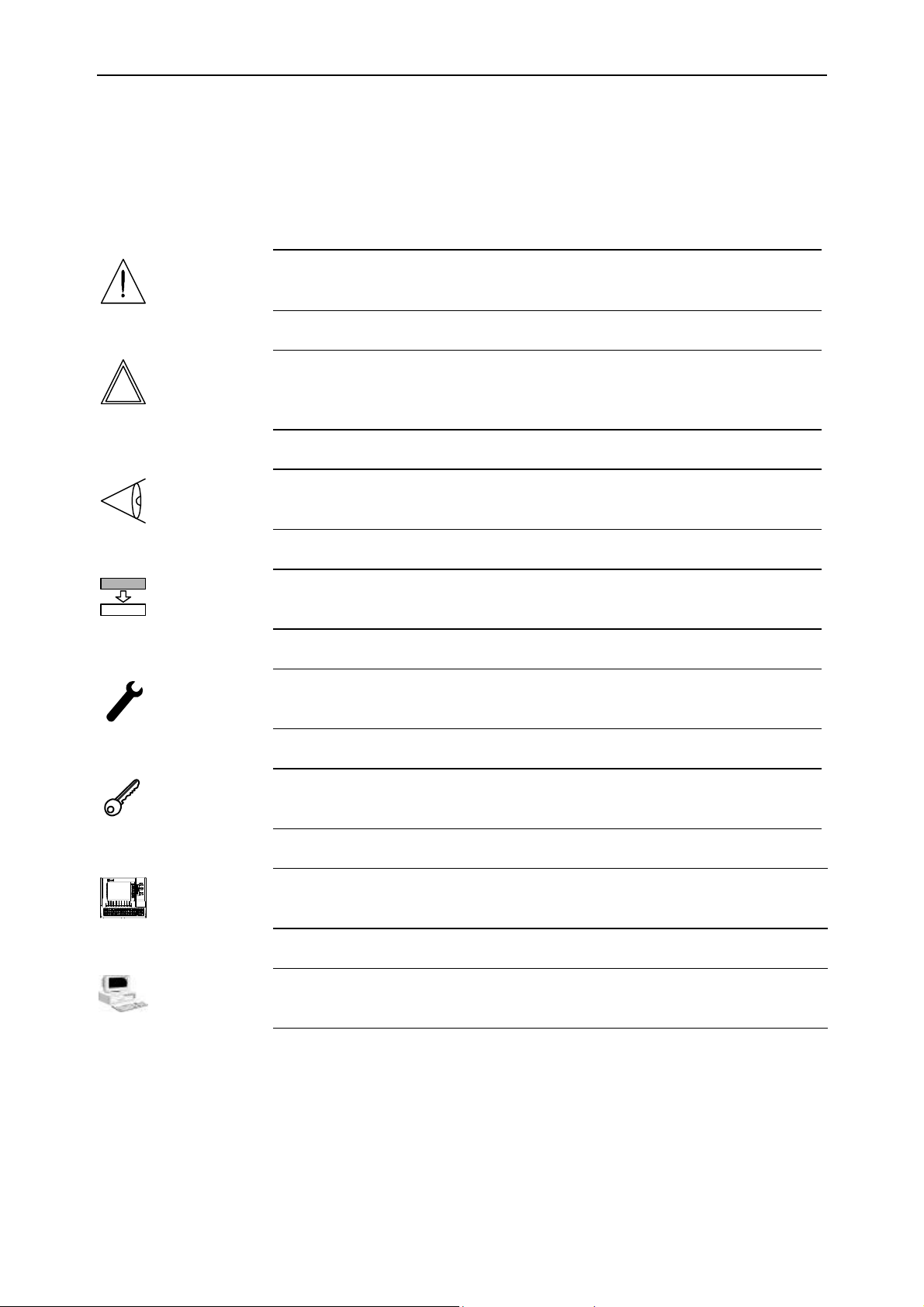
Explanation of the symbols
Graphic symbols may appear beside the text. These are used to emphasize information
of particular importance.
Attention
This symbol is used when failure to take the appropriate precautions could cause
slight damage to persons and property.
Danger
This symbol appears when failure to take the appropriate precautions or
accomplishment of incorrect manoeuvres could cause serious damage to persons
and/or property.
Important
This symbol appears in the manual to indicate information of particular importance. It
is essential to read these sections in order to fully understand the manual.
Option
This symbol indicates sections of the manual that describe optional functions or parts.
Use of optional performances must be established with the machine manufacturer.
Manufacturer
This symbol indicates those sections of the manual reserved to the machine
manufacturer.
Password
This symbol indicates sections of the manual that describe functions access to which is
safeguarded by software passwords.
CN
This symbol indicates sections of the manual that describe functions only available in
CN and not in the PC.
PC
This symbol indicates sections of the manual that describe functions only available in
the PC and not in CN.
91752.GO.0.GB Esa/Gvii
Page 11

GO Notes for the reader
Printer’s conventions
Particular printer’s conventions are used to make it easier to identify the information in
this manual. These conventions are illustrated below.
Keyboard and video The following conventions are used.
ù The names of the screen-printed keys are indicated in boldface and are enclosed
within square brackets. If the name of the key is preceded by “button”, reference is
being made to a key on the push button panel.
− [ENTER]. Identifies the key that bears the word ENTER.
− [+] indicates the + key of the keyboard, while button [+] indicates the + key of
the push button panel.
ù The names of the function keys are indicated in boldface italics and are enclosed
within square brackets.
− [Plc Menu]. Identifies the function key that bears the words Plc Menu.
ù References to fields and/or messages on the video are written in boldface italics.
ù The specific text to be digitized by the user is underlined.
− If the manual indicates “digitize ok, the user must digitize exactly “ok”.
ù DIRECTION or DIRECTIONAL keys is the collective name used to indicate the
UP, DOWN, LEFT and RIGHT keys.
ù Pressure, in sequence, on a series of keys is written by separating the identifiers of
the required keys with the “>“ character.
− [Manual] > [START]. Describes pressure, in sequence, on the [Manual] and
[START] keys.
ù Pressure on several keys at the same time is indicated by separating the identifiers
of the keys themselves with the “+” character.
− [SHIFT] + [àà] Describes contemporaneous pressure on the [SHIFT] and [àà]
keys.
Text The following conventions are used.
ù Italics are used to identify specialistic terms.
ù Boldface is used to emphasize words of particular importance.
Esa/Gv 91752.GO.0.GB iii
Page 12

Notes for the reader GO
Glossary
CNC This is an abbreviation of Computerized Numerical Control and indicates the
instrument that governs the machine, i.e. the electronic device through which the
machining cycles are programmed, the axes moved, etc..
It corresponds to one of the devices whose operation is described in this manual.
NC Represents the Normally Closed status of an input or an output.
NO Represents the Normally Open status of an input or an output.
END OF PREFACE
91752.GO.0.GB Esa/Gviv
Page 13

GO General Description
1.1
1 General Description
1.1 What is BaseMenu
BaseMenu is a tool that, amongst other things, allows you to test the operation of the
NC, enter the parameters and update the CNC files.
The functions it carried out, which are described in this manual, are dedicated to those
who develop automations with Kvara systems or to technicians providing assistance for
customers.
1.1.1 Its functions
In detail, BaseMenu can carry out the following functions:
File Management
Shared Editor
Channel monitor
PLC Menu
Alarms list
IO Redir Editor
Allows files or folders to be copied to and from disks,
including floppy disks or NC disks.
This means that files can be transmitted or received to and
from the FLASH DISK or RAM DISK of the NC. The
firmware can also be upgraded with this tool.
This is the parameters editor of the NC.
This tool is used to configure the operation of the firmware,
to enter the parameters of the axes, the part program
processing channels, etc...
This tool allows the operator to select the operating mode of
each channel, to select the program to execute and to debug
the operation.
This mask displays all the diagnostic information concerning
the operation of work cycles and axes movements.
This is mainly used to load the PLC program of the NC (after
an update). It also gives low level diagnostic information that
can help Esa/Gv technicians sort out NC faults not due to
logic or configuration problems.
Contains the list of all the activated and no longer activated
alarms, thus allowing transitory emergency situations to be
checked.
This tool sets up the configuration of the local and remote
analog and digital I/O devices connected to the NC.
ASCII Editor
Autosetup
A detailed description of the functions is given in the following chapters or this
manual.
Esa/Gv 91752.GO.0.GB
This tool allows any text file to be modified or newly written,
particularly work programs, fixed cycles or sub-programs.
This function must be used with caution. It is used to reprogram the firmware of the CNC. If this function is used
improperly or by unauthorized personnel, the CNC could be
damaged and its operation blocked.
Page 14
General Description GO
1.2
1.1.2 Description of the graphic mask areas
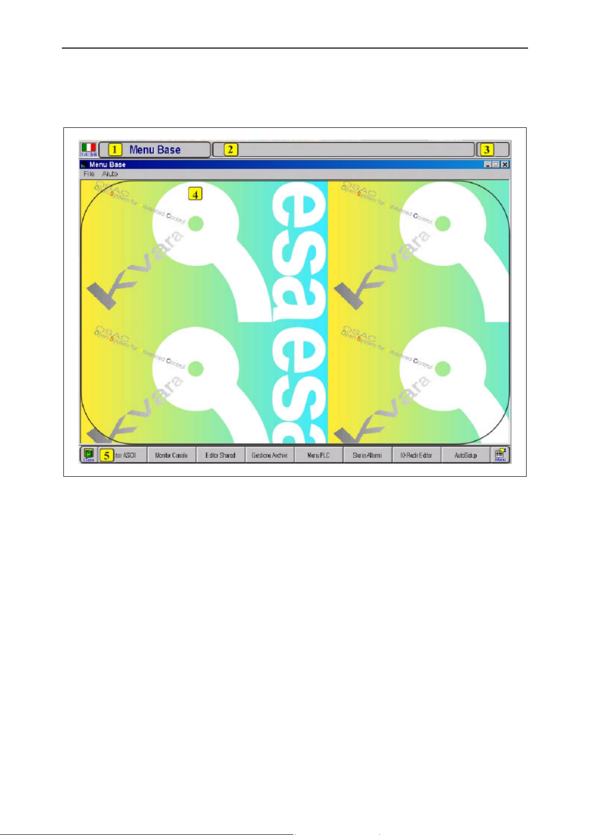
The user interface mask is divided into five zones or areas, as shown in the figure:
Figure 1.1 – Screen division
ù #1: contains information about the machine status or operating status of the CNC
(e.g. BASIC MENU when the machine is powered, CHANNEL MONITOR in
the channel monitor menu, etc.).
ù #2: formed by three lines containing the messages and alarms. The position
(meaning line number) and colour describe the type of message displayed:
− the first line displays the physical emergencies;
− the second line displays the general alarms;
− the third line displays the PLC messages or PLC alarms.
ù #3: contains symbols (or icons). The icons, if visible, have the following meanings:
− key: indicates that a password has been entered;
− disk drive: indicates that the floppy disk drive is operating;
− reference: indicates that the sizing cycle has been executed.
91752.GO.0.GB Esa/Gv
Page 15

GO General Description
1.3
ù #4: used to display information, for data entry and for other functions that allow
the machine to be used.
ù #5: this consists of eight + two graphic keys (boxes) that describe the function
associated at that moment, with the function keys. White graphic keys indicate that
the corresponding function keys are not used by the current session;
The two end keys have fixed functions. The one on the left shuts down the current
mask while the one on the right activates a menu from which the system functions
can be selected.
The remaining function keys, if pressed, activate the functions to which the text
refers.
End of Chapter
Esa/Gv 91752.GO.0.GB
Page 16

General Description GO
1.4
91752.GO.0.GB Esa/Gv
Page 17

GO System functions
2.1
2 System functions
2.1 Introduction
Press the [Menu] key to activate the system menu for access to all the general functions
of the machine. The system menu is can be activated from any software mask selected.
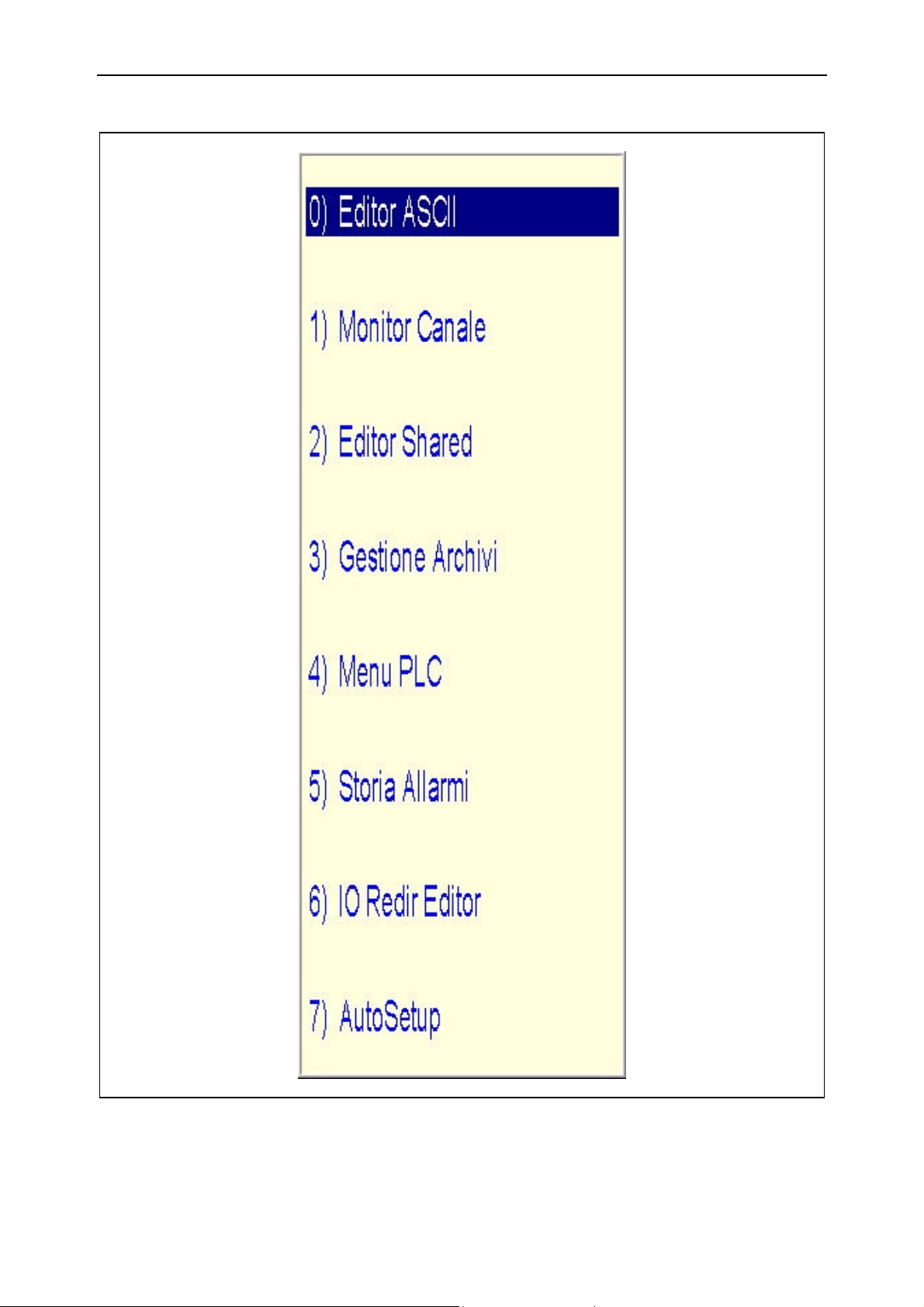
2.2 System menu
The system functions are as follows:
ù ASCII editor
ù Channel monitor
ù Share editor
ù File management
ù PLC menu
ù Alarm list
ù Autosetup
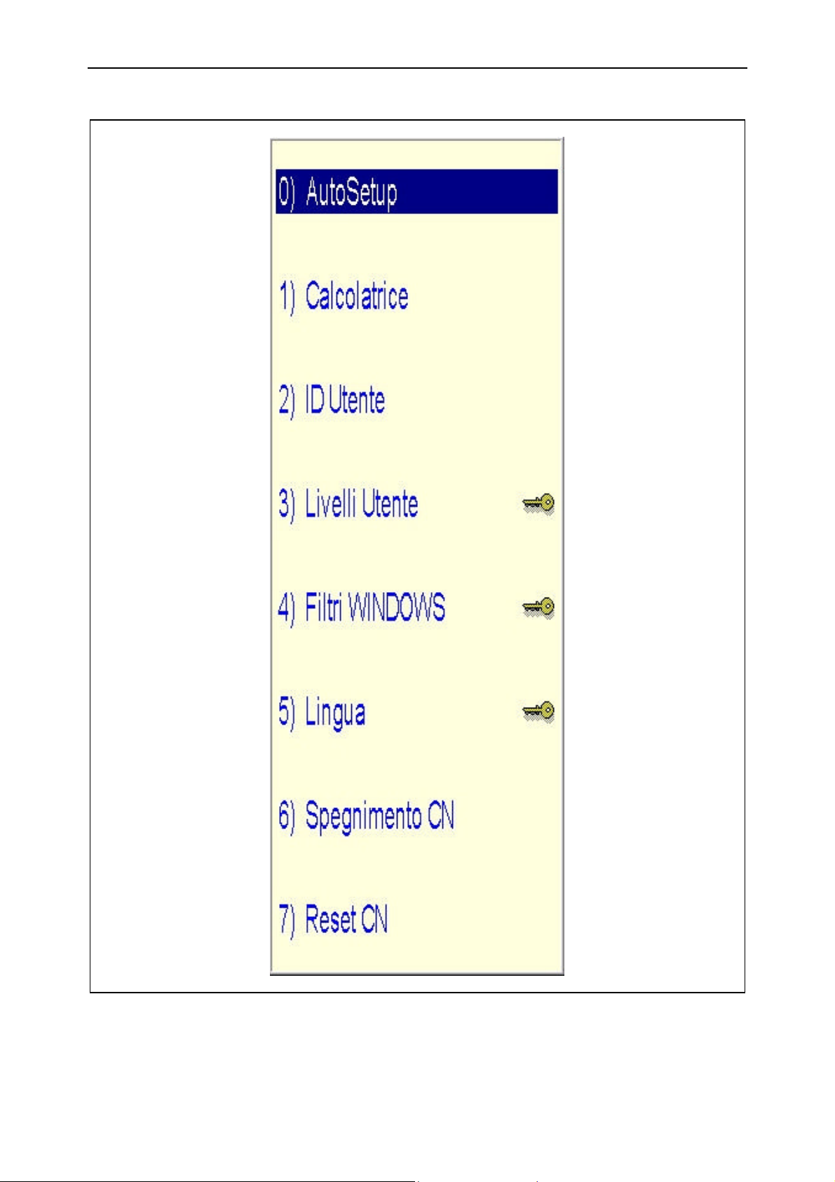
ù Calculator
ù User ID
ù User levels
ù Windows filters
ù Language
ù NC shutdown
ù NC reset
Esa/Gv 91752.GO.0.GB
Page 18
System functions GO
2.2
Figure 2.1 – System menu
91752.GO.0.GB Esa/Gv
Page 19
GO System functions
2.3
Figure 2.2 – Second System menu
Esa/Gv 91752.GO.0.GB
Page 20

System functions GO
2.4
Use the [↑↑] and [↓↓] keys to select the required menu item, then press [ENTER] to
activate it.
Use the two function keys on the right (under the menu) to scroll between the
first and second menu.
2.2.1 Alarm list
To display the mask with the chronological list of all active and activated alarms,
select the Alarms List item from the system menu and press [ENTER].
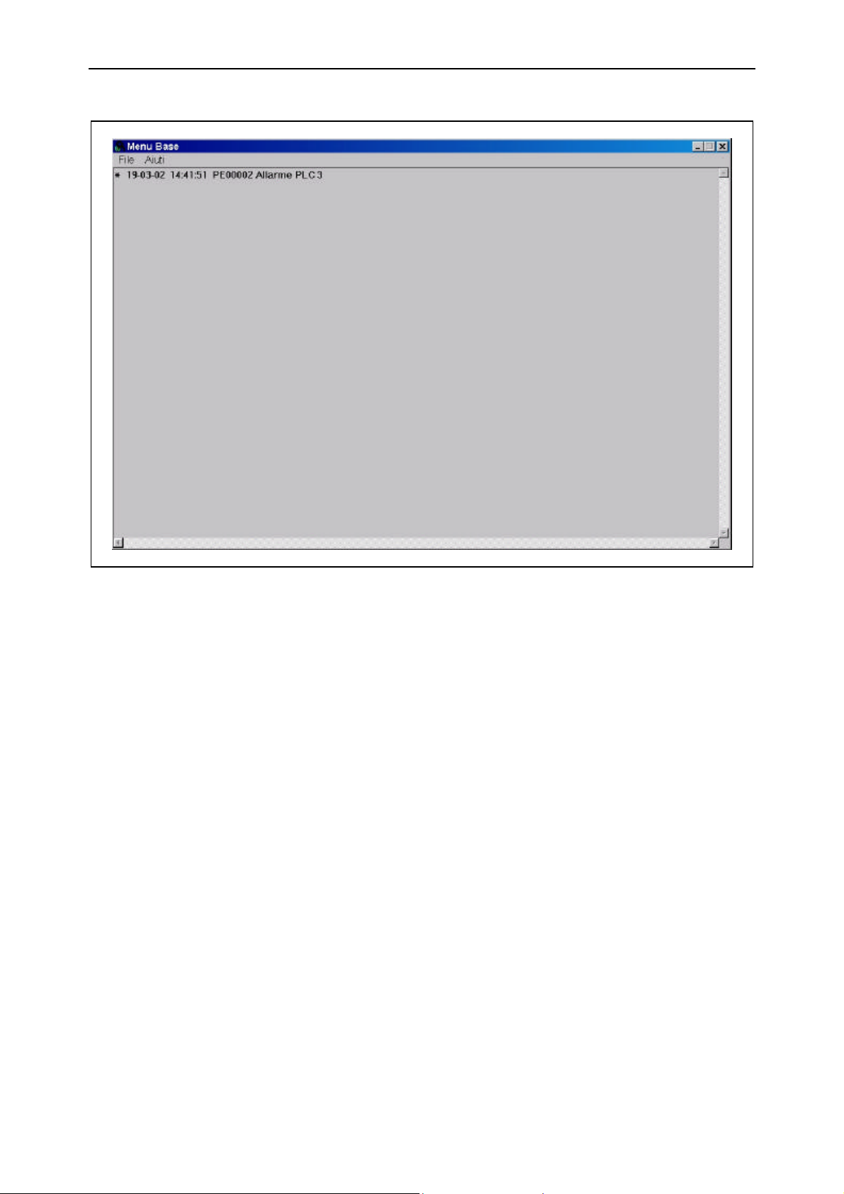
The window accessed consists of several lines, each of which described an alarm. The
following information is given:
Date and time of
activation
Associated code number
Full description
All the alarms activated during the last 30 days are displayed. Older alarms are
eliminated from the memory and can no longer be displayed in this mask.
Give the date and time at which the alarm activated. The
date format is “day-month-year” and the time format is
“hours-minutes-seconds”. If the date is preceded by the
‘*’ character, this means that the alarm is activated at that
moment.
This consists of five figures. It represents the numeric
code of the alarm.
Gives the nature of the alarm in more detail.
91752.GO.0.GB Esa/Gv
Page 21
GO System functions
2.5
Figure 2.3 – Alarms window
If the mask is completely filled with information about the alarms, use the [PgUp] and
[PgDn] keys to display any information that does not appear.
Alarm updating
PLC message display This mask can also display messages activated by the PLC that are not alarms and that
How to save alarms
on disk
Press [Cancel] to cancel any no longer activated alarms (without an asterisk). Press
[Update] to update the alarms status and add any others that may have activated in the
meantime.
are not mixed with the alarms for this reason.
Press [Alarms/Messages] to switch to the PLC message display. Press this key again to
go back to the alarms display.
To save the alarm status in a file, press [Save Alarms], specify a file name and then
press [ENTER] on a level with the dialogue window in order to save the displayed file.
This function is of particular use since it allows the manufacturer’s after-sales service
staff or the retailer of the machine to diagnose faults.
The saved file can be sent to the after-sales service center where the technicians can
examine it and come up with a solution to any problems that may occur during use of
the machine.
Esa/Gv 91752.GO.0.GB
Page 22

System functions GO
2.6
2.2.2 User ID
The window where the password is entered or cancelled can be activated from the
system menu by selecting the User ID item and pressing [ENTER].
The CNC is able to carry out all the functions required to operate the machine without
requiring any password. Password entry enables certain functions that require specific
knowledge of the CNC and/or the machine.
Password entry
How to annul the
password
Digitize the password in the window displayed and press [ENTER].
Password entry is confirmed by the key symbol that appears in the top right-hand part
of the screen.
Press the [Clear password] button in the password entry window.
The key symbol will disappear from the top right-hand part of the screen to confirm
that the password has been annulled.
It is always advisable to annul the password when it is no longer necessary to have it
entered. This avoids accidental access to risky functions and prevents protected data
from being modified.
91752.GO.0.GB Esa/Gv
Page 23
GO System functions
2.7
2.2.3 Calculator
To activate the calculator, select the Calculator item from the system menu and press
[ENTER].
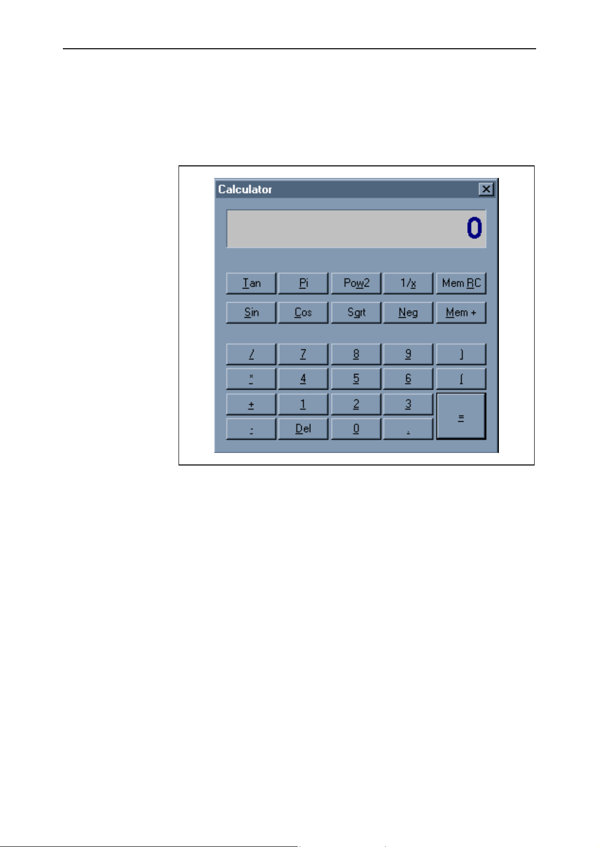
The calculator is shown in the following figure:
Figure 2.4 - Calculator
The calculator is divided into three zones (as are all normal calculators):
ù the display
ù the functions
ù the basic operators and numbers
The display The display can contain up to 15 characters. The M character can also appear on the
left to indicate that the memory contains a value and the symbol of the operation set
up.
Esa/Gv 91752.GO.0.GB
Page 24

System functions GO
2.8
The functions The available functions are listed below:
Function Description
Tan Calculates the tangent of the value set on the display
Pi Enters the p (pi) value on the display
Pow2 Squares the value set on the display
1/x Calculates the reciprocal of the value set on the display
Mem RC Recalls the value from the memory and enters it on the display.
A second pressure cancels the value from the memory.
Sin Calculates the sine of the value set on the display
Cos Calculates the cosine of the value set on the display
Sqrt Calculates the square root of the value set on the display
The basic operators
and numbers
Neg Changes the sign of the value set on the display
Mem+ Adds the value set on the display to the memory
Besides the numeric keys, the basic operators are to be found in the lower part of the
calculator:
Function Description
+ Sets up the addition operator
* Sets up the multiplication operator
- Sets up the subtraction operator
/ Sets up the division operator
Del Cancels the value from the display
( Increases the open brackets level (the open brackets level appears in the
lower left part of the display)
) Decreases the open brackets level (the open brackets level appears in
the lower left part of the display)
= Calculates the result of the operation set.
91752.GO.0.GB Esa/Gv
Page 25

GO System functions
2.9
2.2.4 Work language selection
To select the work language, go to the BASIC MENU and press the [Menu] key. This
action will access a small system menu containing the service menu. Select the
Language item with the [↓↓] and [↑↑] keys and press [ENTER].
A window containing flags representing the available languages will now appear on
the screen. Use the [←←] and [→→] arrows to select the required language and confirm
with [ENTER].
The CNC now informs the user that the change will only be activated after the
program has been restarted. Confirm the restart request.
2.2.5 How to turn off the CNC
Once you have decided to turn off the CNC, proceed with the shutdown procedure. Go
to the BASIC MENU and activate the service window. Now select the Shutdown item
with the [↓↓] or [↑↑] keys and confirm with [ENTER]. The CNC will now carry out the
Windows TM shutdown procedure.
2.2.6 Standard functions
The remaining functions of the system menu, not described, activate the function
associated with the menu item in the same way as the same functions on the BASIC
MENU function keys. Consult the relative chapters for explanations about these
functions.
These functions can be activated by means of the system menu without closing the
selected mask (i.e. by going back to the BASIC MENU). In this case, several
BaseMenu masks are opened. The * character alongside the system menu item
indicates that the mask of the corresponding function is activated and that when
selected, the control will be transferred to it again.
Press [Ctrl] + [Tab] to select one of the activated masks. BaseMenu proposes the next
mask activated. Repeat the operation until you reach the mask required.
Esa/Gv 91752.GO.0.GB
Page 26
System functions GO
2.3 Open and Save dialogue masks
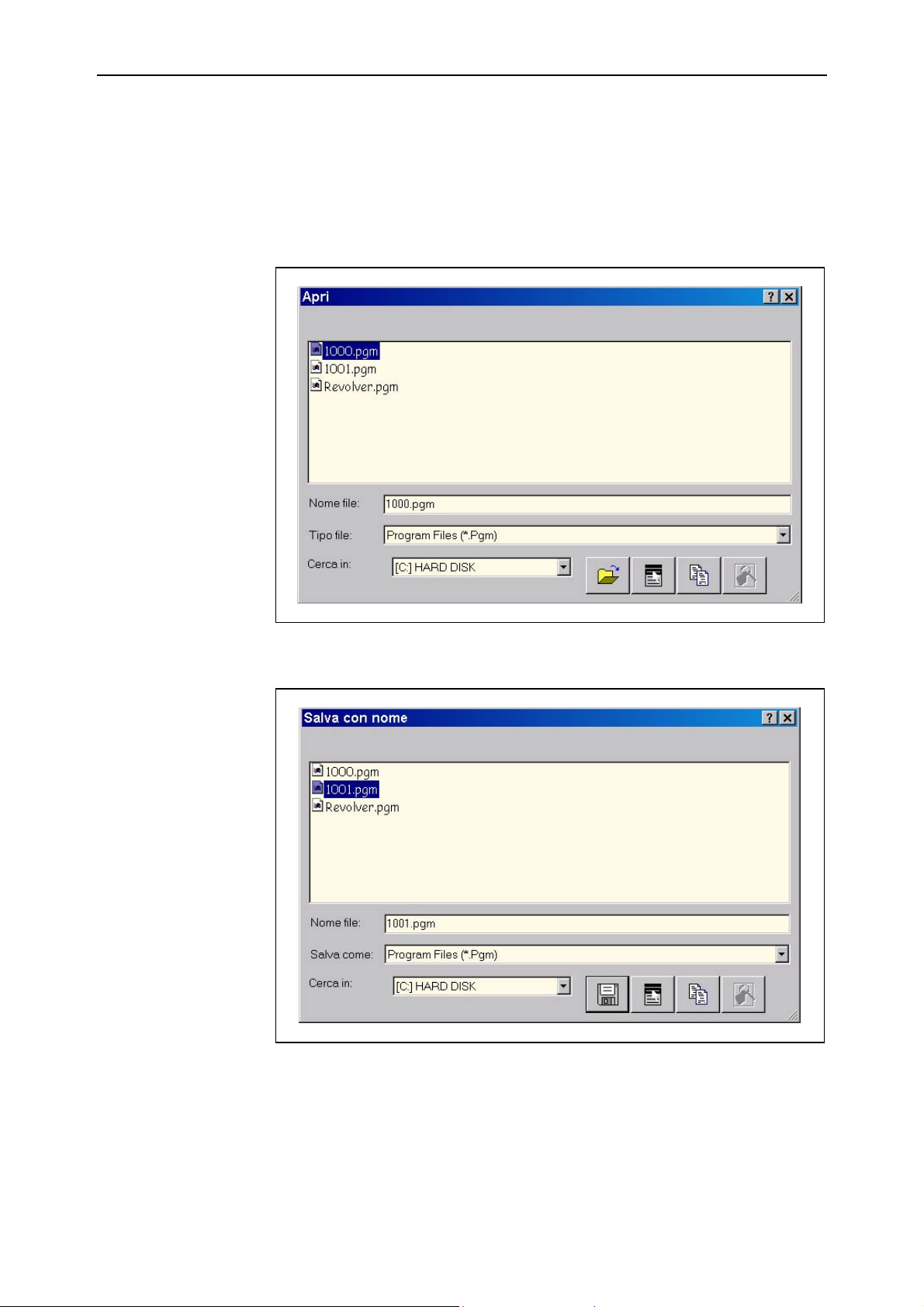
During normal use of the CNC, when file opening and saving operations are carried
out, the CNC dialogues with the operator in windows called Open/Save dialogue
windows.
Figure 2.5 – Dialogue window for file opening
Figure 2.6 –Dialogue window for file saving
The various types of dialogue window respond to the standard Windows ™ commands:
91752.GO.0.GB Esa/Gv2.10
Page 27
GO System functions
File selection Two methods can be used to select the files to Open/Save:
ù Select the file required with the [↓↓] [↑↑] [←←] [→→] keys and press [ENTER];
ù Press [TAB] until you reach the entry field and digitize the name. If one or more
characters must be cancelled during the digitizing phase, position the cursor with
the [←←] and [→→] keys:
− to the right of the character to be cancelled, then press [BACKSPACE], or
− to the left of the character to be cancelled, then press [DEL].
Open or Save Proceed in one of the following ways to confirm the opening or saving action:
ù press [ENTER] after having selected the required item from the list, or
ù use [TAB] to select the button (saving window) or the button (opening
window) and press [ENTER].
File deselection
Change folder
Folder creation
File or folder
renaming
To deselect a file in the Open/Save windows, press [Ctrl] + [SPACE]. Deselection is
required to access certain functions that would otherwise be impossible to execute, such
as folder creation for example.
To change the folder used for reading or saving, press [BACKSPACE] to go back to
the higher level or select one of the directories from the list and press [ENTER]. Now
repeat the sequence until you reach the required directories.
Warning: if the cursor has been previously moved from the area containing the list of
files, it must be brought back to this area by pressing [TAB]. Only then may the
described selection be applied.
To create a folder, first deselect the selected file, then use the [TAB] key to scroll the
various controls in sequence until reaching the button. Now press [SPACE]. A
window containing certain functions will now appear. Use the [↓↓] or [↑↑] keys to
highlight the New item in the menu and press [→→] to access a second window where
the Folder element can be selected (using the same method). Now press [ENTER].
The windows are closed and a new item depicting a folder will be proposed in the list
with the name, New Folder highlighted. Digitize the new folder name and press
[ENTER].
Select the file or folder to rename. Use the [TAB] key to scroll through the various
controls in sequence until you reach the button and press [SPACE]. A window
containing several functions will now appear. Use the [↓↓] or [↑↑] keys to highlight the
Rename item and press ENTER.
The window will be closet and the old name of the item selected will be highlighted.
Now digitize the new name for the selected item and press [ENTER].
Esa/Gv 91752.GO.0.GB 2.11
Page 28

System functions GO
File or folder deletion
File duplication
Annul
Select the file or folder to cancel. Use the [TAB] key to scroll through the various
controls in sequence until you reach the button and press [SPACE]. A window
containing several functions will now appear. Use the [↓↓] or [↑↑] keys to highlight the
Cancel item and press ENTER.
Select the file to duplicate. Use the [TAB] key to scroll through the various controls in
sequence until you reach the button and press [SPACE]. A window where the
name of the newly duplicated file must be entered will appear. Do this and press
[ENTER].
Press [ESC] to close the displayed dialogue window.
End of Chapter
91752.GO.0.GB Esa/Gv2.12
Page 29
GO File Management
3.1
3 File Management
3.1 Introduction
This chapter describes how to use the File Management function of KVARA.
File management operates directly with the storage device and memory of the NC.
Some of the more delicate operations are protected by passwords.
Improper use of these functions can prevent the NC from operating correctly.
Remember to take the utmost care and do not carry out hasty manoeuvres.
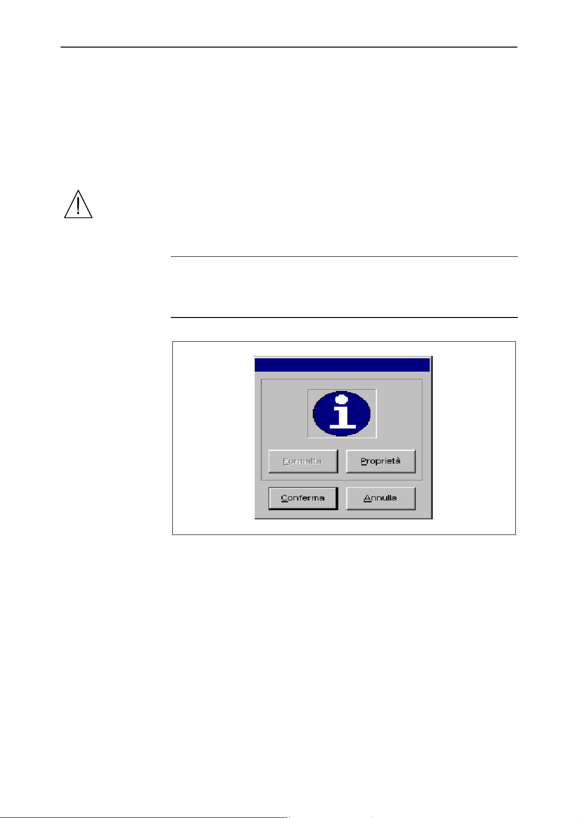
NOTE
Figures showing the buttons whose use is described in the chapter appear on the
following pages. The messages on the buttons include an underlined letter. This letter
is known as short-cut and indicates the key to press along with the [ALT] key in order
to directly activate the button function.
E.g.:
Figure 3.1 -
Press [ALT]+[C] to activate the [Confirm] button
Press [ALT]+[A] to activate the [Annul] button
Esa/Gv 91752.GO.0.GB
Page 30
File Management GO
3.2
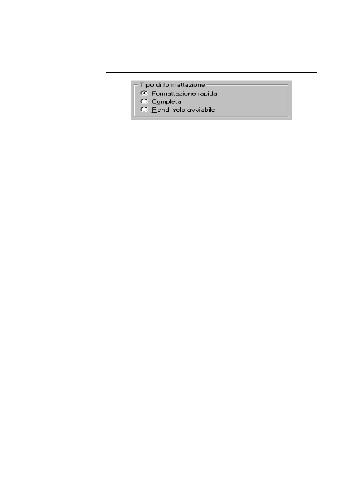
This is also valid for the windows with options.
Figure 3.2 -
91752.GO.0.GB Esa/Gv
Page 31
GO File Management
3.3
3.2 File management Mask Interface
Refer to the “System Functions” chapter for instructions on how to access the FILE
MANAGEMENT function.
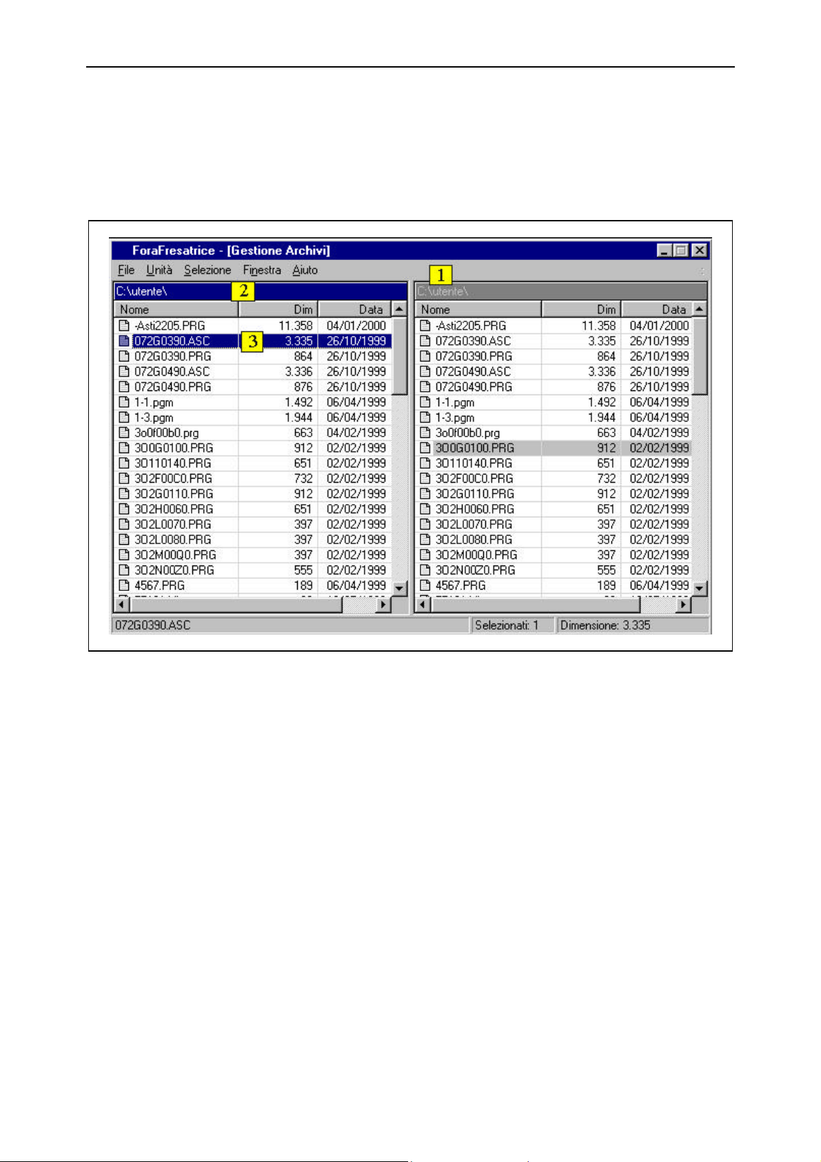
Figure 3.3 - File Management mask
1) Name of selected unit
2) Activated window
3) Selection bar
As can be seen in Figure 3.3, the mask has two windows. Each window contains the
list of files in the unit shown at the top in area 1. The functions described in the
horizontal keys are operative from the activated window to the non-activated one.
E.g.: [Copy] copies the files from the activated window to the non-activated one.
A window is activated if its title is blue in colour and the selection bar appears on the
list of files.
Esa/Gv 91752.GO.0.GB
Page 32
File Management GO
3.4
3.2.1 Window selection
File management sets the selection bar in a window and makes it activated. If you wish
to activate the other window on the screen, just press the [TAB] key. Press the [TAB]
key again to go back to the first window selected.
Another way to do this is to use the right and left arrows of the keyboard.
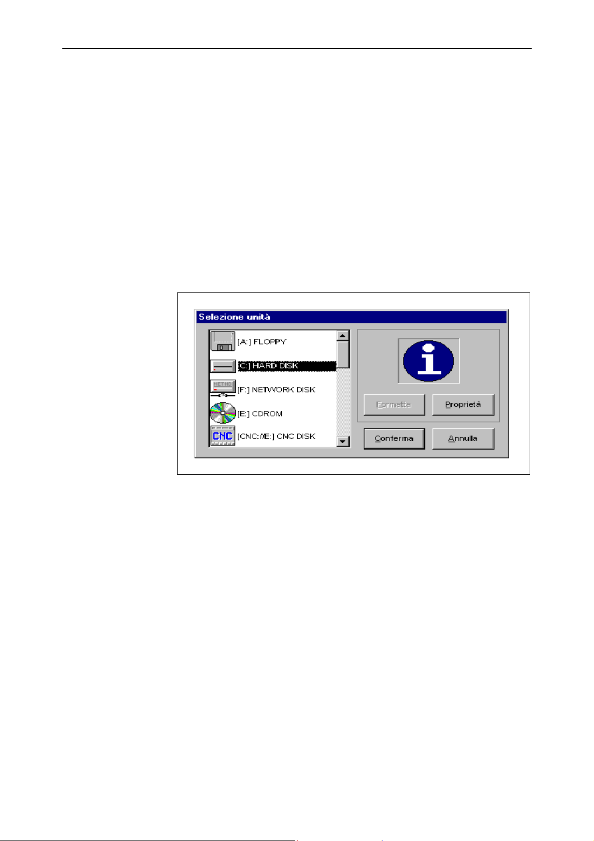
3.2.2 How to select a Unit
Unit selection is available by means of the [Change Unit] key.
1) Select the window in which you intend to change units.
2) Press the [Change unit] key.
3) Scroll through the list of accessible units and choose the one required.
4) Press [ENTER] to confirm the selection or [ESC] to annul it.
Figure 3.4 - Unit selection
3.2.3 How to select one or more Files
To select one File:
1) Set the selection bar on the file to select.
2) Press [INSERT].
To select a consecutive list of files:
1) Set the selection bar to the first file.
2) Press [SHIFT] + the down arrow on the keyboard until the last file to copy has
been selected.
3) Press [INSERT].
The selected file or files are highlighted by a blue bar. Press the [INSERT] key on one
of these files to deselect it.
91752.GO.0.GB Esa/Gv
Page 33
GO File Management
3.5
3.2.4 File copying
To copy one file:
1) Select the window and the unit in which the file is to be copied.
2) Switch to the other window by means of the [TAB] key.
3) Select the unit containing the file to be copied.
4) Set the selection bar on the file to be copied.
5) Press [Copy].
To copy several files:
1) Select the window and the unit in which the files are to be copied.
2) Switch to the other window by means of the [TAB] key.
3) Select the unit containing the files to be copied.
4) Select the files to copy.
5) When all the files to copy have been selected, press [Copy].
If the destination disk already contains the file to be copied, it will be overwritten
without any warning.
3.2.5 Filtered selection and deselection
Another, very quick way to select files, is filtered selection. This selection mode allows
the operator to enter a selection criterion, such as selection of all the files with the
same extension for example.
To select files by means of the filtered selection mode:
1) Select the window and the unit in which the files are to be selected.
2) Press [Filtered selection].
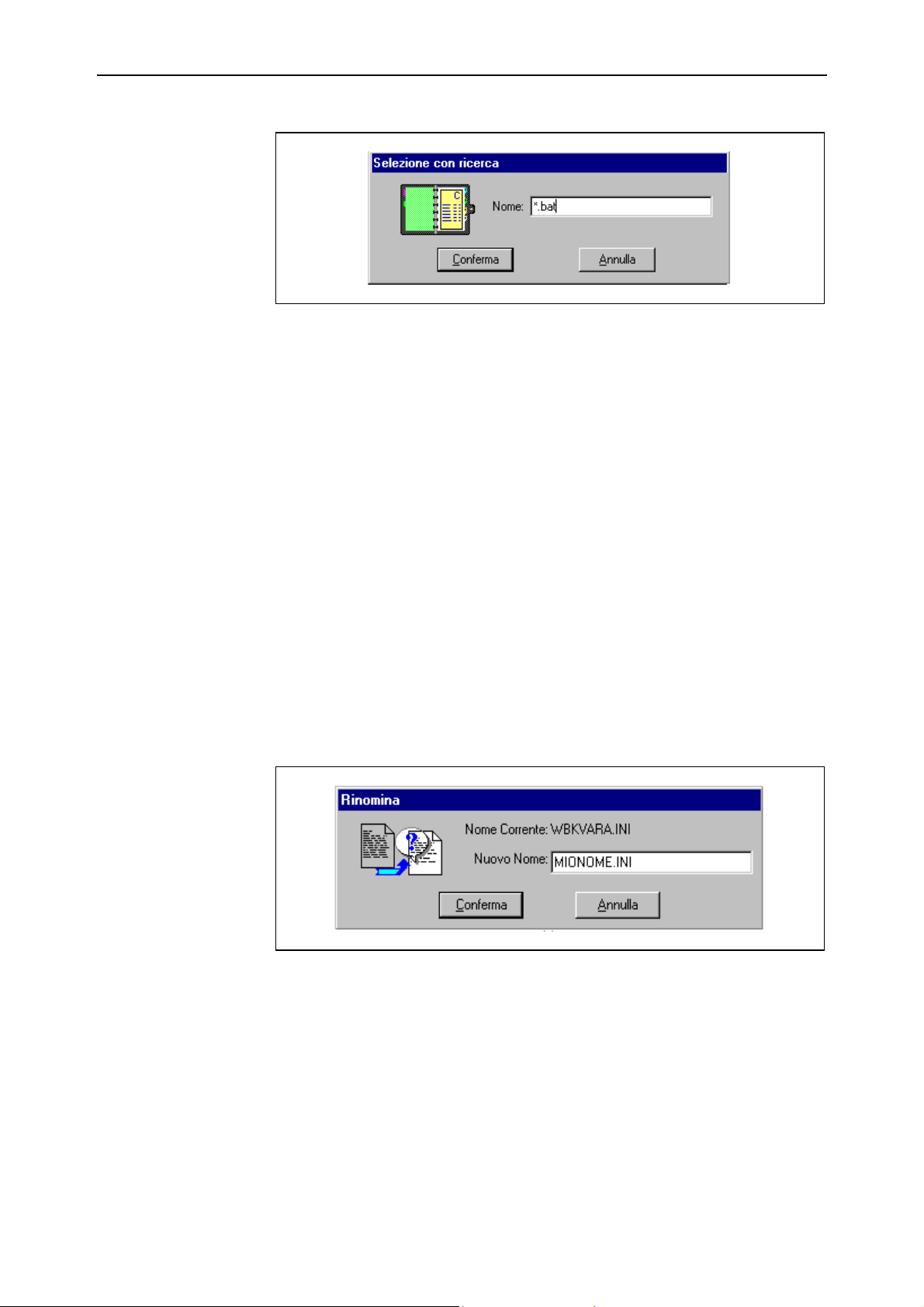
3) Digitize the selection criterion in the window that appears (E.g.: *.bat ).
4) Press [ENTER] to confirm the selection or [ESC] to annul the selection.
At the end of these operations, all files that conform to the entered selection criterion
will be highlighted in blue.
The deselection procedure functions in the same way but obtains the opposite result,
i.e. it deselects the files that conform to the entered deselection criterion. If no file has
been selected, it will evidently be impossible to deselect any.
Esa/Gv 91752.GO.0.GB
Page 34
File Management GO
3.6
Figure 3.5 - Filtered selection
3.2.6 How to cancel one or more Files
To cancel one or more files:
1) Select the files to cancel.
2) Press [Eliminate].
Since file cancellation is a destructive operation, a window with a request to confirm
cancellation will appear.
If you are sure that the file must be effectively eliminated, press [Yes], otherwise press
[No].
3.2.7 How to rename a File or Folder
To rename a file or folder:
1) Set the selection bar to the file or folder to be renamed.
2) Press [Rename].
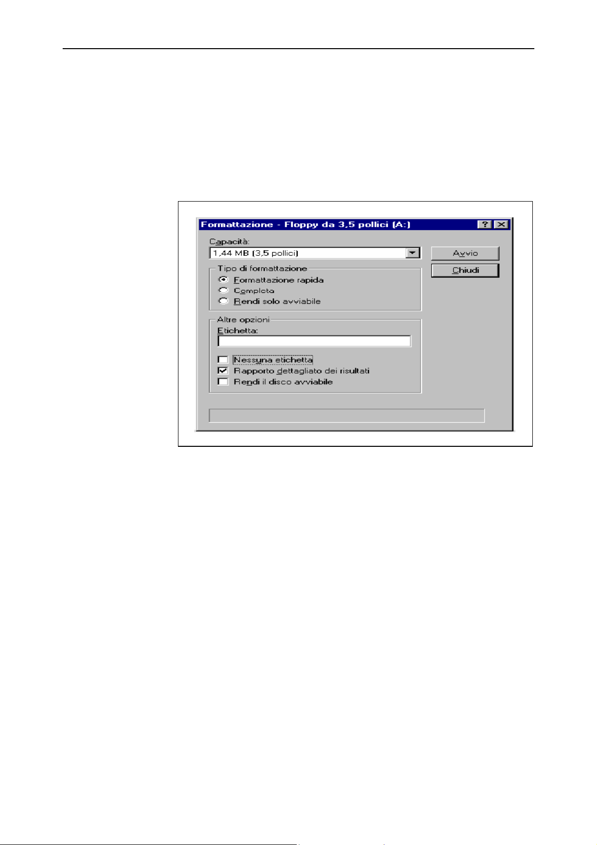
3) Digitize a new name (maximum 128 characters) in the window that appears.
4) Press [ENTER] to confirm or [ESC] to annul.
Figure 3.6 - File or folder renaming
91752.GO.0.GB Esa/Gv
Page 35
GO File Management
3.7
3.2.8 How to format a disk
Formatting a unit is one of the most delicate operations that the operator can carry out
in File Management mode. For this reason, not all units can be subjected to it, just the
Floppy Disk and the CNC unit. While Floppy disks can always be formatted, a special
password must be entered in order to format the CNC units. If the password has not
been correctly entered, the formatting key will be disabled.
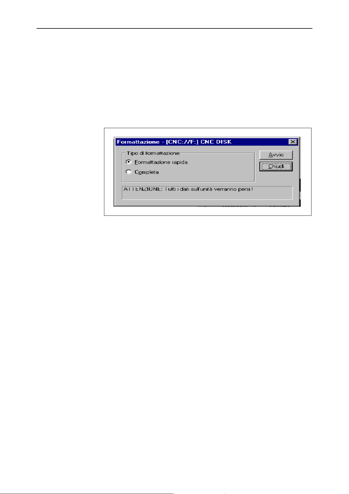
The following window will appear when the Floppy Disk is formatted:
Figure 3.7 - Formatting the Floppy Disk
Esa/Gv 91752.GO.0.GB
Page 36
File Management GO
3.8
To format a unit:
1) Select the disk to be formatted.
2) Press [Format] [ALT]+[F] (If the key cannot be accessed, it means that the correct
password has not been entered).
3) Select the type of formatting required in the window that appears (complete
formatting, i.e. [ALT]+[O] is recommended).
4) Start the formatting process with [Start]. Press [Close] if you wish to interrupt the
operation.
Figure 3.8 - Formatting
91752.GO.0.GB Esa/Gv
Page 37
GO File Management
3.9
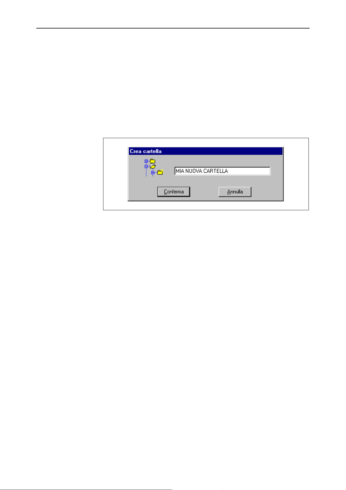
3.2.9 How to create a new folder
A folder is a container used to organize files.
Creation of a new folder:
1) Select the required unit.
2) Press the [New Folder] key.
3) Digitize the name of the folder (maximum 128 characters) in the window that
appears.
4) Press [ALT] +[C] to confirm the creation or [ALT] + [A] to annul folder creation.
Figure 3.9 - Creation of a new Folder
Esa/Gv 91752.GO.0.GB
Page 38

File Management GO
3.2.10 How to access and quit a folder
The folders can be distinguished from the files by means of the <DIR> symbol
alongside the name of the folder.
To access:
1) Position the selection bar on the required folder.
2) Press [ENTER].
To quit:
1) Position the selection bar on the first line of the list with the folder symbol, with
an arrow pointing upwards.
2) Press [ENTER].
This function is not available if you are in the main folder.
3.2.11 Changing the file order
The order in which the files are displayed is established by a set-up that can be
modified by pressing the [Order] key.
One of the following elements can be selected from the window that appears:
ù Name
ù Dimension
ù Date
ù Time
corresponding to the available methods by which the files can be set in order.
Selection
Use the [↓↓] and [↑↑] keys to select the order mode and then press [ENTER] to confirm
the selection.
End of Chapter
91752.GO.0.GB Esa/Gv3.10
Page 39
GO Parameters Editor
4.1
4 Parameters Editor
4.1 Introduction
This chapter describes the functions available in the machine parameters editino mask.
Refer to the “Description of the Machine Parameters” manual for a detailed
description of each parameter.
Activation
To activate the parameters editor from the BASIC MENU, press [Parameters], select
the type of parameter to display or modify from trhe window displayed above the
depressed key and then press [Enter].
The following options are available:
ù Tool Parameters
Accesses the configuration parameters of the boring head and the actuators
associated with the tools.
ù General Parameters
Accesses the configuration parameters of the work surface, the axes and the
general machine data.
ù Configuration Parameters
Accesses the configuration parameters of the serial ports and machine options.
Incorrect modification of these parameters can lead to faulty operation or totally stop
the machine. Inexpert persons or those who are not fully familiar with the machine
should therefore not carry out such operations.
Some of the parameters can only be modified by users recognized via software
passwords. However, all parameters remain visible. The protection level of each
parameter is given in the “Description of the Machine Parameters” manual.
Closing
Esa/Gv 91752.GO.0.GB
Press the [Close] key to shutdown the parameters editor.
Page 40

Parameters Editor GO
4.2
4.2 Parameters Mask
Once activation of any of the available tables has terminated, the program will access
the management phase for the selected category of parameters.
The mask is divided into two separate areas
1) Hierarchical Parameters Tree
2) Editing Area
The part that contains the hierarchical tree represents the logic organization of the
parameters tables while the editing area displays the parameters of the element selected
from the tree.
4.2.1 Work Area
This area is accessed by pressing [Work Area]. On activation, this area of the
parameters editor is already activated.
The area displayed is a tree structure with expandable branches representing the
hierarchy of the parameters. The node to which the program has positioned is shown in
yellow.
The tree is initially closed. To open it at a level, press [→→] on a level with the branch
that needs expanding. Press [←←] to close the selected branch.
Use keys [↓↓] and [↑↑] to scroll through the tree elements.
When the icon of the selected element of the tree is a table, press [Enter] to update the
editing area.
4.2.2 Editing Area
This area is accessed by pressing [Editing Area].
The editing area is used to modify and display the parameter data. It consists of a
variable number of white coloured editing fields preceded by a string that identifies the
meaning of the parameter.
A parameter is modified by digitizing the required value. When [ENTER] is pressed,
the value is checked and, if correct, is confirmed, otherwise the previous value is
restored.
Use the [↑↑] and [↓↓] keys to scroll through the fields in the table. The current field can
be recognized by the YELLOW coloured background.
4.2.3 How to select an element from the table
Some tables can consists of several masks, i.e. it may contain several homogeneous
elements. Press [Next] to select the mask following the one displayed. Press [Previous]
to select the previous mask.
To select the mask to display, press [Select Table], indicate the number of the table to
display in the dialogue window that appears and then press [ENTER].
91752.GO.0.GB Esa/Gv
Page 41

GO Parameters Editor
4.3
How to copy the data
of the current table in
a selected table
To copy the data in the displayed table into a new table, press [Select Table], indicate
the number of the table to display in the dialogue window that appears, enable the
Copy data into new element option and press [ENTER].
4.2.4 How to save parameters
To save the displayed table of parameters, make sure that the selected area is the
editing area, then press [Save Parameters].
To save a different table from the one selected, activate the work area and select the
node associated with the required table, then press [Save Parameters].
Save all parameters Select the first node of the tree (the one on which all the other nodes depend), then
press [Save Parameters] to save all the tables associated with the sub-nodes.
4.2.5 Parameter loading
To load the displayed table of parameters, make sure that the selected area is the
editing area, then press [Load Parameters].
To load a different table from the one selected, activate the work area and select the
node associated with the tables required, then press [Load Parameters].
Save all parameters Select the first node of the tree (the one on which all the other nodes depend), then
press [Load Parameters] to load all the tables associated with the sub-nodes.
4.2.6 Contextual Help display
Select the Display helps function from the Options menu to display the contextual
Help for the parameter indicated by the cursor.
A third window will appear on the right-hand side of the screen. This window may
contain the following information:
ù A textual description of the current parameter
ù A graphic display of the current parameter.
Both these items may be present or just one of the two or even none, depending on the
parameter selected.
If present, they give the most significant piece of information concerning the current
parameter.
If repeated, this activation procedure deactivates the contextual help option.
Enf of Chapter
Esa/Gv 91752.GO.0.GB
Page 42

Parameters Editor GO
4.4
91752.GO.0.GB Esa/Gv
Page 43
GO I/O Editor
5.1
5 I/O Editor
5.1 Introduction
The I/O editor is a tool that allows the peripheral boards connected to the CNC to be
configured.
Only the local (connected straight to the NC) or remote (connected by optic fiber using
the Esa/Gv proprietary bus) produced by ESA/GV can be configured with this
instrument.
Activation
Press the [I/O Redir Editor] key from the BASIC MENU mask to activate the I/O
editor.
5.2 Graphic aspect
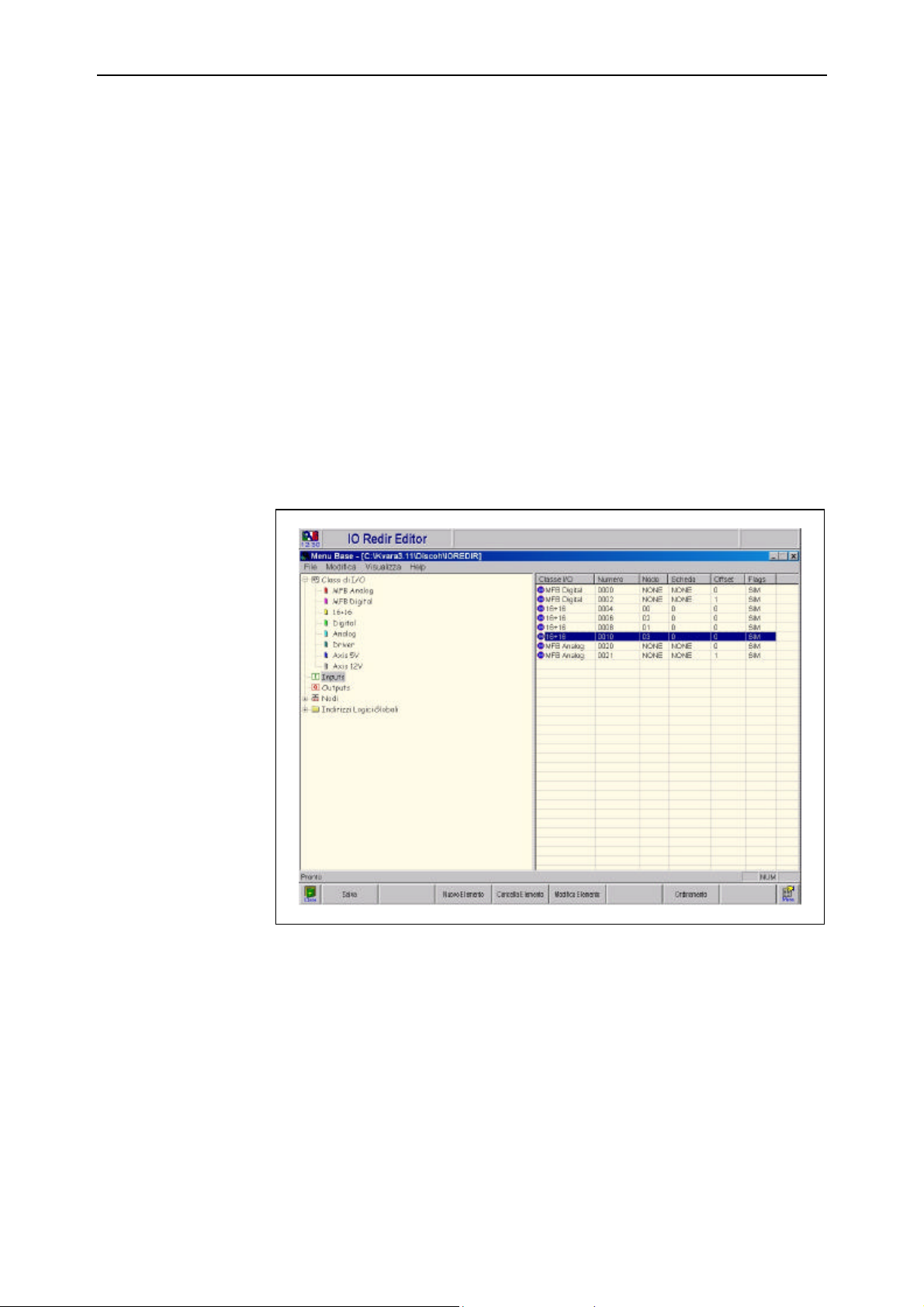
The I/O configuration mask is depicted in the following figure:
Figura 5.1 -
It is divided into two parts. There is a browser on the left and a table containing the
data concerning the item selected by the browser on the right.
Browser The browser gives different views of the database in which the editor works. In
particular, it allows access to the information organized in the following way:
Esa/Gv 91752.GO.0.GB
Page 44
I/O Editor GO
5.2
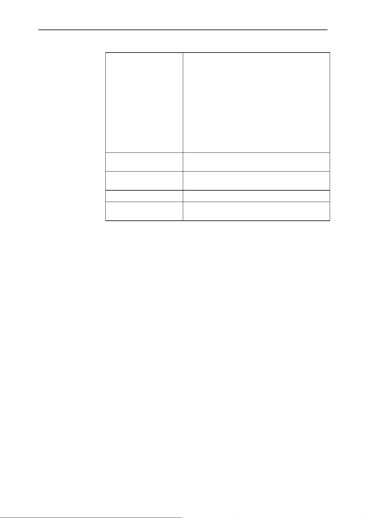
I/O categories Board division per type:
ù Local analogs
ù Local digitals
ù 16 remote Inputs + 16 remote Outputs
ù Remote digitals
ù Remote analogs
ù Remote drivers (not used)
ù 5 V remote axes
ù 12 V remote axes
Inputs List of all the boards configured as inputs (both local
and remote).
Outputs List of all the boards configured as outputs (both local
and remote).
Node Displays the composition of each individual node.
Logic addresses Displays the logic representation of the I/Os in the
memory.
Data entry table The right-hand part of the mask contains information about the item selected by the
browser.
This area is used to enter the data of a new board or to modify already existing settings.
91752.GO.0.GB Esa/Gv
Page 45
GO I/O Editor
5.3
5.3 I/O editor functions
The functions carried out by the I/O editor concern configuration of the peripheral
device to use.
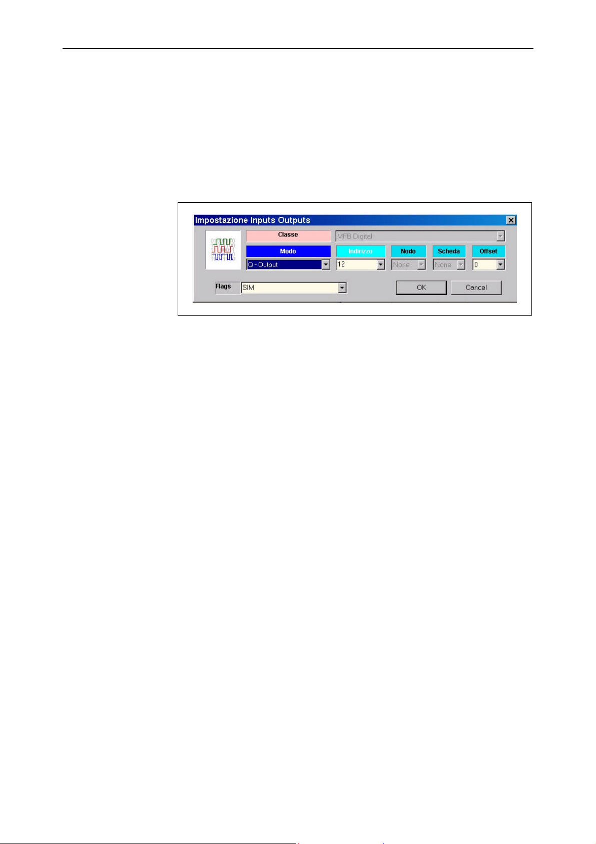
Board insertion In order to insert a board, first select the category of I/O to which the board belongs by
means of the browser
Figura 5.2 -
End of Chapter
Esa/Gv 91752.GO.0.GB
Page 46

I/O Editor GO
5.4
91752.GO.0.GB Esa/Gv
Page 47
GO Channel monitor
6.1
6 Channel monitor
6.1 Introduction
Channel monitor is a tool that allows the operation of each ISO channel configured to
be controlled and verified.
The information in this mask concerns a single channel.
Activation
Role of the PLC with
the Channel Monitor
Press the [Channel Monitor] key in the BASIC MENU status to access the
CHANNEL MONITOR mask.
Many of the functions described below are only activated if a PLC program that
implements them is being executed. The controls that the Channel Monitor supplies to
the relative channel transit via the PLC which may customize the information or will at
least copy it into the channel registers. If PLC scanning is not activated or the PLC
program does not implement all the available functions, then the Channel Monitor will
only operate in partial mode.
6.2 Graphic display
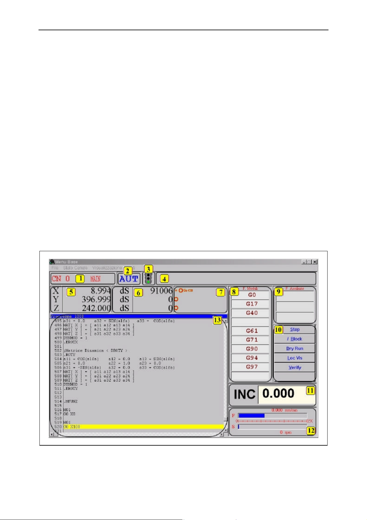
The channel monitor is divided into various areas as shown in the figure.
Figura 6.1 -
Esa/Gv 91752.GO.0.GB
Page 48

Channel monitor GO
6.2
1) Number and name of current channel
2) Channel status
3) Status semaphore of the program. Only of significance if the selected mode is
AUT.
4) Display of the string associated with a $ command in the part program.
5) Channel axes targets
6) Additional information about the axes
7) Status icons of each axis
8) List of activated G modal functions
9) List of activated M, T, D functions
10) Function control buttons
11) Target for fixed increases (significant when the channel is in the INC status)
12) Override value display
13) List of the program selected or being executed with current line indication.
Some of the functions modify the aspect of the graphic mask, but not in a significant
wa. Areas 8, 9, 10, 11 and 12 are overwritten by a table that lists the parametric values
and their contents.
6.3 Detailed description of the information displayed
A great deal of the information displayed in this mask can be published by the channel
interpreter or executor. The difference lies in the fact that display in phase with the
interpreter is asynchronous in relation to real execution while display in phase with the
executor is synchronous.
Display in phase with the executor is certainly more significant during the debugging
operation. However, it introduces generation of an instrumental code to synchronize
the display. This leads to a loss of efficiency of a sometimes significant entity. The
parameter that influences this type of operation is Display in phase with interpreter in
the NC Options table. If it is 0 , the display will be in phase with the executor; if it is 1,
the display will be in phase with the interpreter.
It is advisable to select 1 for this parameter at the end of the part program test phase,
i.e. when the machine must begin the customer’s production cycle. This parameter can
be modified at any moment. The NC need not be reset, since the parameter is acquired
whenever a part program is executed, i.e. display in phase with the executor can be
restored if assistance work is required.
6.3.1 Axes information
Areas [5], [6] and [7] contain information about the axes belonging to the channel.
This information must be interpreted per line through all the areas indicated.
Targets Area [5] contains the current axes targets. The values are displayed in millimeters or
inches, depending on the unit of measurement chosen.
91752.GO.0.GB Esa/Gv
Page 49

GO Channel monitor
6.3
Additional
information
Follow error
DAC voltage
Area [6] contains additional information concerning the axis with which it is aligned.
The information to display in this area can be chosen from amongst the following
options:
ù Follow error Ess
ù DAC voltage V
ù Distance from target ds
To modify the type of information displayed, press the [Alt] + [V] keys and select the
information from the pull-down window proposed.
This information is given in millimeters or encoder pulses, depending on how a
machine parameter has been set up (Parameter set version in the General parameters
table. Enter 1 for values displayed in millimeters or 0 for values displayed in pulses..
Warning: this parameter influences various other axes parameters. It must therefore
not be used to solely select the unit of measurement of the follow error).
This information is useful when the dynamics of axes that must interpolate with each
other must be set up. Interpolation will be correct if, speed being equal, all the axes
that must interpolate with each other have an equal follow error.
This information indicates the voltage that the NC supplies to the indicated axis drive.
This value is equivalent to the one that can be measured with a multimeter on the
analog output channel of the axis.
Its values can be between 0 and 10 Volt, even though 10 Volts are normally never
measured as this would mean saturating both the DAC converter and the drive. The
maximum value given by the NC on the output depends on the drive set-up.
Distance from the
target
The icons Area [7] contains a series of icons that supply information about the status of each axis.
This information displays the distance the axis needs to cover in order to reach the
programmed point. When the axis has arrived and stops, the value is 0. The instant in
which the axis starts to position, the maximum value is displayed, i.e. equivalent to the
distance between the starting point and the point to reach.
In the JOG and REF status, the value displayed is not the distance from the target
(which is not known) but the distance covered from the beginning of the movement.
They are displayed in real time and provide important information about debugging.
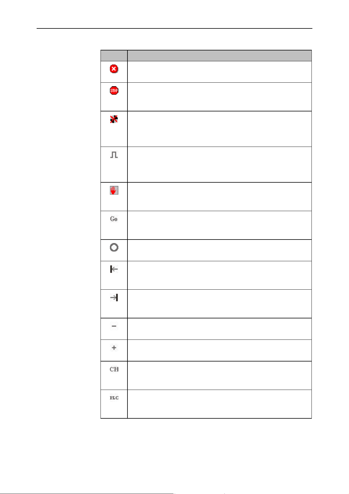
All the possible icons that can be displayed are listed below. The display of one does
not exclude the others as several icons can be present at the same time in order to give
a compound status of each axis.
Esa/Gv 91752.GO.0.GB
Page 50
Channel monitor GO
6.4
Symbol Description
EMERGENCY
The axis is in the emergency status.
AXIS STOPPED
Indicates that the axis is at a standstill. This information concerns the
theoretic position, i.e. minus follow error recovery.
AXIS NOT SIZED
The axis has not yet been sized, i.e. the zero search cycle (homing) has not
been carried out. This signal disappears at the end of the sizing cycle and
does not appear again until the NC is newly powered.
ZERO MARK
Signals that the czero mark is activated in the current axis position. This
icon is displayed on each encoder turn. However, in view of the brief
duration of the zero mark, this icon may not be visible at high speeds.
ADVANCEMENT BLOCK
Indicates that the advancement block is activated. In this case, the axis
cannot move even if requested to.
ON MOTOR
Indicates that the drive must be enabled for the axis (activation of ONMOTOR).
CLOSED LOOP
The regulating ring is activated, thus the axis is controlled.
LOWER LIMIT
The lower software limit has been reached. The axis cannot move towards
negative targets, just towards positive ones.
UPPER LIMIT
The upper software limit has been reached. The axis cannot move towards
positive targets, just towards negative ones.
NEGATIVE DIRECTION
The axis is moving towards negative targets.
POSITIVE DIRECTION
The axis is moving towards positive targets.
AXIS CONTROLLED BY ISO
The axis is being managed by the CHANNEL and is thus controlled by an
ISO part program.
AXIS CONTROLLED BY PLC
The axis is managed by the PLC and is thus controlled by means of the
function blocks that govern movement via the PLC.
91752.GO.0.GB Esa/Gv
Page 51
GO Channel monitor
6.5
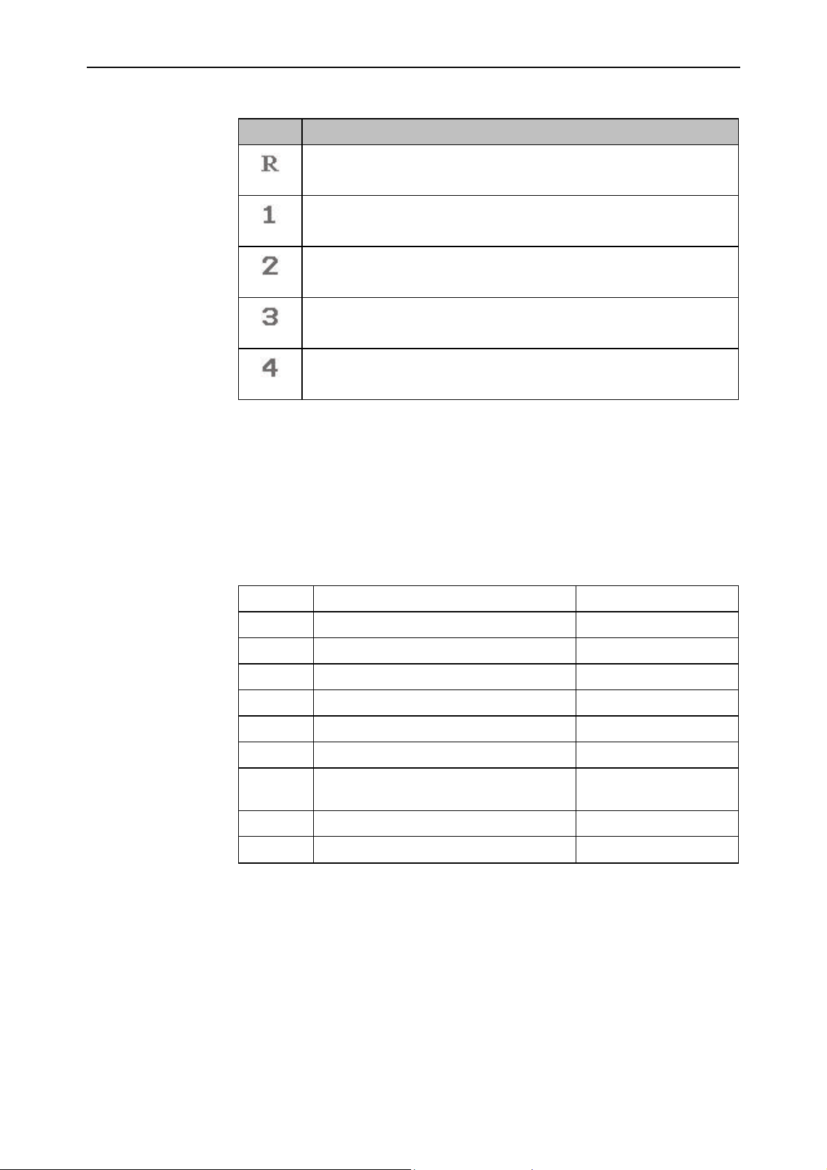
Symbol Description
REVOLVER
The axis is indicated as REVOLVER for turret change management.
SPINDLE RANGE 1
The spindle is working in the first range programmed.
SPINDLE RANGE 2
The spindle is working in the second range programmed.
SPINDLE RANGE 3
The spindle is working in the third range programmed.
SPINDLE RANGE 4
The spindle is operating in the fourth range programmed.
6.3.2 Information about the program status
The information listed below is determined by execution of a part program that causes
the change.
Modal functions Area [8] of the modal functions contains 10 groups where the activated G functions are
displayed. Each group contains the value of the last G programmed from amongst
those of the group that exclude each other.
Group 1 Movements G0 – G1 – G2 – G3
Group 2 Plane selection G17 – G18 - G19
Group 3 Tool corrector selection G40 – G41 – G42
Group 4 Workpiece origin selection G54 – G55 – G56 – G57
Group 5 Continuous mode selection G61 – G64
Group 6 Inches / millimeters G70 – G71
Group 7 incremental / absolute G90 – G91
Group 8 Selection of mode in which speeds are
expressed
Group 9 Rotation speed / constant cutting G96 – G97
Group 10 Fixed cycles
G93 – G94 – G95
G100 ⇒ G999
At the start, the default values are displayed while the currently used values will be
displayed during execution. A field without a value means that the group has no
default value and that none of the codes of that group have yet been executed.
Esa/Gv 91752.GO.0.GB
Page 52

Channel monitor GO
6.6
Auxiliary functions Area [9] of the auxiliary functions contains 3 groups where the activated T, D, M
functions are displayed.
A field without a value means that the group has no default value and that none of the
codes of that group have yet been executed.
The last values programmed of each of the T, D and M functions are displayed in these
fields. The values of these functions are only overwritten when a new, homogeneous
function is executed.
Speed display Area [12] has two slide bars that give the percentage programming of the axes and
spindle override and the programmed speed value for both.
The slides have a 150% full scale (maximum override value accepted by the channel).
The bar indicates the set percentage.
The programmed speed is also displayed for both fields, concerning the axes (F) and
the spindle (S): in mm/min for the axes and in RPM for the spindle.
The speeds displayed are the programmed ones, thus with reference to a 100%
override.
6.3.3 The window of the selected program
Area [13] displays the list of the selected program.
The display activates when a valid program is selected.
The name of the selected program (or an error if the program is not found) appears in
the upper part of the window.
The program list is flanked by the displayed line number.
As soon as program execution begins, a yellow bar appears showing the currently
executed line. The displayed portion of program is automatically centered in a frame
around the current line so that this is always visible.
If the program is not being executed, the scroll bars of the window can be used to
display parts of the program that are not visible.
91752.GO.0.GB Esa/Gv
Page 53

GO Channel monitor
6.7
6.4 Channel Monitor functions
The main channel monitor functions available are described below.
6.4.1 Required channel selection
The first thing to do when the channel monitor is activated is to select the number of
the channel required. When activated, the channel monitor proposes the first channel
configured (normally N° 0).
The selection is made by pressing the [Select Channel] key and digitizing the required
channel number.
Instead of entering the number, the selection can be made by entering the name
associated with the channel (if set in the channel parameters).
In this case, instead of digitizing the channel number, press [TAB] and enter the
required channel number. In both cases, confirm the selection with [ENTER].
If the number or name of the selected channel is not correct or not configured,
selection will have no effect.
6.4.2 Current axis selection
One of the axes may be highlighted in a different colour in area [5] of the channel
monitor mask, i.e. that of the axes targets. This is the current axis, i.e. the axis
subjected to the single axis JOG, INC or REF movements.
Use the [↓↓] [↑↑] keys to modify the axis selection. This action highlights the next or
previous axis.
This is a function that requires the intervention of the PLC. Whenever the above
mentioned keys are pressed, the channel monitor transmits a selection request to the
PLC which must be confirmed by this latter. Display occurs on confirmation from the
PLC. This mechanism allows an external selector that uses physical inputs to be
inserted for example. Since the PLC does not have to deal with the requests of the
channel monitor, it is thus able to write the value of the selector in the response
register, bypassing management of the arrow keys in favour of the external selector.
The PLC can also force any axis as current axis according to internal logics known to
the PLC programmer.
Axis selection behaviour is thus strongly influenced by the PLC program. So much so,
this latter could also stop the current axis from being displayed.
Current axis display is hidden by the channel monitor in the AUT and MDI statuses.
6.4.3 Channel status selection
Press the [Channel Status] key to select the channel status. A pull-down menu with a
complete list of the available statuses will appear:
ù REF Reference, axes zero search cycle
ù JOG Manual movement of the selected axis
ù INC Incremental movement of the selected axis
ù MDI Manual Data Input, execution of an entered ISO block
ù AUT Automatic, execution of the selected part program
Once a status has been selected, the channel is ready to receive commands pertaining
to the status activated.
Esa/Gv 91752.GO.0.GB
Page 54

Channel monitor GO
6.8
REF status The PLC can activate the search cycle for the axes zeros. The cycle accomplished
depends on a machine parameter (Type of Sizing in the Axes Parameters table) which
establishes the sequence of the positionings made. A further parameter establishes the
direction of movement (Sizing direction reversal opt. in the Axes Parameters table),
while another two parameters define the speeds used (Micro search speed in siz. and
Mark search speed in siz. In the Axes Parameters table).
The REF cycle can be executed simultaneously for all the axes or with wired sequences
in the PLC logic.
JOG status The channel accepts axes movement commands in this status. The JOG movement
commands will probably be enabled by inputs that select the direction of movement.
Movement normally terminates by the input being released.
If the axis in movement has been sized, a JOG movement will never take the axis
beyond its limits. When these are neared, the NC begins its deceleration ramp even
though the movement input remains activated, and is thus able to stop on the exact
lower or upper limit of the axis.
Vice versa, if the axis has not been previously sized, its movement cannot be
controlled, thus the safety overtravel signals can be reached.
The speed used for these movements is expressed by a parameter that may differ for
each of the axes configured (Manual Speed in the Axes Parameters table).
INC status The operation of this status is almost the same as that of JOG. The only difference is
that axis positioning occurs from the current target of the selected axis onwards, for the
distance set in the area [11] (fixed increase). For example, if X axis is on target
255.000 and a forward increase with target INC=44 is requested, the axis will be
moved to 299.000.
The speed used for these movements is the maximum speed of the axis.
MDI status Selection of the MDI status allows a special program, the MDI program, to be executed
in automatic mode. Mode activation activates the [MDI] key that allows the ISO blocks
to be executed in this status to be inserted.
AUT status This status allows an ISO program to be executed. As usual, selection of the program
to execute is the task of the PLC. The contents of the selected program are displayed in
screen area [13].
91752.GO.0.GB Esa/Gv
Page 55

GO Channel monitor
6.9
6.4.4 Movement in JOG mode
A single axis can be moved in the JOG status. Movement begins when the operator
presses a button and stops when this button is released.
There are normally two buttons, one for movement towards positive targets and one for
movement towards negative targets.
Activation First select the JOG status, then select the axis to move. After this, use the movement
buttons (depending on the PLC program) to move the selected axis in the positive or
negative direction.
The FORWARD and BACKWARD signals cannot be given at the same time.
6.4.5 Execution of a sizing cycle
Execution of a sizing cycle is of fundamental importance if the minimum and
maximum limits of the moving axes are to be used in full. A sizing cycle must be
executed whenever the CNC is powered.
Activation Select the REF status of the channel. Now press the sizing cycle button.
The axes sizing sequence is established by the PLC.
6.4.6 Positioning to incremental targets
Incremental movement is a status in which a positioning is carried out where the
distance to cover is known, to the detriment of the coordinate to reach.
The CNC calibrates the target of the selected axis and generates a positioning to target
increased (or decreased) by a programmed value.
Given DS as the programmed movement, Q0 as the current axis target and Qt the
required target, this latter is calculated in the following way:
Activation
Qt = Q0 + D
Qt = Q0 - D
Select the INC status and the axis to position. Now enter the positioning value (DS) by
pressing key [Inc. Target] and entering the required value in millimeters. Confirm
with [Enter].
Execution of a positive positioning is obtained by using the FORWARD movement
command provided by the PLC logic. Vice versa, a negative positioning is obtained by
using the BACKWARD movement command.
Release of the positioning key will not stop the axis which always terminates the
activated positioning, unless an emergency occurs.
S
S
for positive increases
for negative increases
Esa/Gv 91752.GO.0.GB
Page 56
Channel monitor GO
6.4.7 JOG OPEN function
The JOG OPEN function allows the NC to be used as a reference signal generator for
drive sizing. In this status, the NC supplies a programmed voltage which is maintained
for as long as the signal remains activated. The wave shape generated includes the
acceleration and deceleration ramps.
Activation Select the JOG status and the axis to which JOG OPEN must be applied. Now press
the [Test] key. The [Jog Open] button is enabled in area [10]. It must be pressed. Now
enter the JOG OPEN voltage by pressing the [Jog Target] key. The value entered will
be expressed in Volts and must be within the 0 - 10 Volt range.
The commands provided by the PLC for JOG activation must now be used.
Consider that the command normally used for movements towards positive targets in
JOG mode leads to a positive voltage output. Vice versa, the command used for
movements towards negative targets leads to a negative voltage output.
The JOG OPEN voltage is maintained until the signal used for command execution is
released.
No checks on the axes limits are conducted in this status even when the axes have been
previously sized. It is the task of the person who works with the CNC to prevent
collisions on the axes hardware protections.
Deactivation
Press the [Jog Open] button again and then press [Test End] to deactivate the JOG
OPEN status.
6.4.8 Direct programming of an ISO block (MDI)
The MDI mode allows a program to be extemporaneously written and immediately
executed without having to quit the channel monitor.
CNC operation in this mode is the same as in the automatic mode.
Activation Select the MDI status. The aspect of area [13] changes and the displayed program
name becomes MDI.
Now press the [MDI] key, which is only enabled in this status. This action opens an
editor which proposes a blank sheet where the ISO instructions required can be
digitized.
There are no limitations in this programming phase in relation to normal
programming of a part program to execute in automatic mode.
When the ISO blocks have been written, press [Execute] and the newly created
program will appear in channel monitor area [13] just like a normal work program.
Press the machine button to start a normal work cycle.
Press the [MDI] key again to open the editor which will propose the previously written
program. This can be modified as required.
91752.GO.0.GB Esa/Gv6.10
Page 57

GO Channel monitor
6.4.9 How to modify the current axis parameters
The parameters of an axis must often be modified during the set up phase. The channel
monitor allows a quick selection to be made for the table of parameters of each axis
associated with the channel without having to pass by the shared editor.
In actual fact, this function is a link with the shared editor which is called up by the
channel monitor in user-friendly mode and presents the parameters table of the
selected axis alone.
This function is only activated if one of the following statuses is selected:
ù JOG
ù REG
ù INC
It is not available in the AUT and MDI statuses. Moreover, an axis must be selected.
The function in question proposes the data of the currently selected axis.
Activation
In the presence of the conditions described above, press the [Test] key and then the
[Axes/Man Parameters] key. The mask containing all the selected axis data will be
created in the right-hand part of the channel monitor.
The required data can now be modified. Terminate this function by pressing [Monitor]
and then [Test End].
The entered parameters will now be activated. The axis uses the new values for the
next positionings.
Esa/Gv 91752.GO.0.GB 6.11
Page 58
Channel monitor GO
6.5 Program execution
Program execution is strongly conditioned by PLC implementation. In some cases, this
latter assigns the number of the program to execute without taking the requests from
other entities into account. This is the case of channels that always use the same
program or programs whose selection is conditioned by the machine status.
In other cases, the User Interface dedicated to the application notifies the selection to
make by means of dedicated registers.
The Channel Monitor also notifies the selection of programs in dedicated registers. If
the PLC takes the information provided into consideration, it will then back the
function in question.
Activation
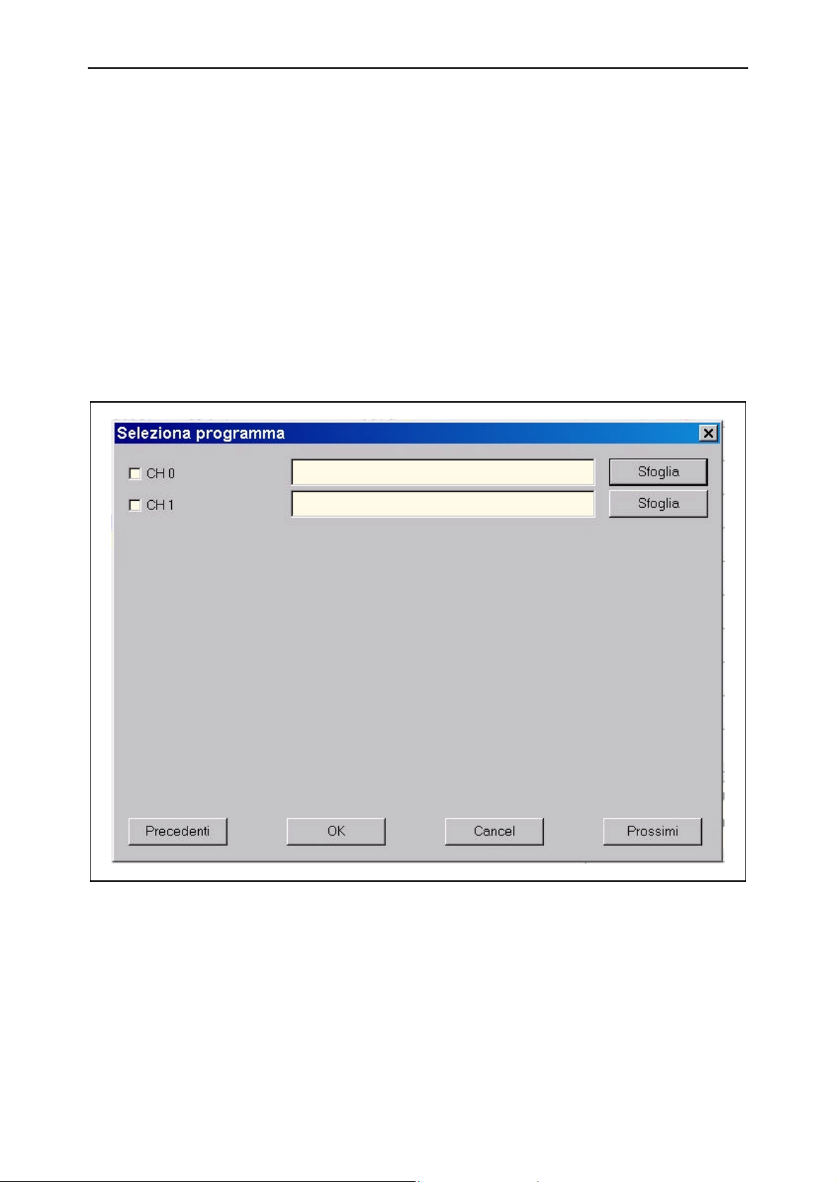
First select the AUT status, then select the program to execute by pressing the [Select
Program] key. The following file selection window will be proposed:
Figura 6.2 -
All the configured channels are listed. Any of the configured channels can be selected
by means of the selection window.
Select the check-box alongside the required channel then digit the names of the files to
execute for each of the selected channels.
The file to execute can also be selected by means of a disk browser by pressing the
[Scroll] button.
91752.GO.0.GB Esa/Gv6.12
Page 59

GO Channel monitor
In particularly complex machines, the number of configured channels will exceed the
maximum number of channels that can be displayed in the window. In this case, use
the [Next] and [Previous] keys to scroll through the list of channels.
Once the operations have terminated, press [Ok], or [Cancel] to annul the selection
made.
The window of area [13] displays the first part of the program selected for the current
channel.
Execution Once selected, the program must be executed by means of the cycle start button, in
accordance with the PLC logic.
The semaphore The start of program execution turns on the GREEN light of the program. This
remains until execution ends, after which it goes out.
If the channel detects a programming error during execution, besides signaling the
occurrence by means of the alarms manager, it will also turn on the RED light of the
channel. This light will remain on until the PLC has reset channel operation.
The YELLOW light comes on after a HOLD request, i.e. when the axes are stopped in
their trajectory, and goes out after the work cycle has been reset.
6.5.1 Selection of the execution mode
Program execution can be influenced by certain execution modes:
ù Step-by-step execution Step
ù Barred block execution / Block
ù Dry Run execution Dry Run
ù Display of workpiece / machine origins Disp Loc
ù Syntactical correctness checks Verify
These modes are activated by pressing the dedicated button in area [10].
If the colour also changes after the key has been pressed, this means that the PLC has
acquired the request. Vice versa, the channel monitor will have transmitted the request
but the PLC will not have taken it into consideration and the selected function will not
have been activated.
Press the button again to disable the function.
Step This operating mode forces the channel to execute one line at a time, stopping the
execution while awaiting an enabling signal on each line. The PLC usually requires the
operator to press a button in order to execute the next instruction.
The step mode is used to verify the correctness of the program or to check the
trajectory of the programmed axes in order to avoid collisions with mechanical parts.
The step function is calibrated at the beginning of the cycle and is maintained for the
entire duration of the program execution cycle.
Barred Block The barred block execution mode allows ISO blocks to be written into a program and
to decide whether to execute it or not at the last moment without having to modify the
file.
Esa/Gv 91752.GO.0.GB 6.13
Page 60

Channel monitor GO
The ISO blocks that have this property must be preceded by the “/” character. Enabling
of barred block execution includes all the blocks in question. Vice versa, blocks whose
first character is the bar will not be executed.
All the NON-BARRED blocks are executed in both modes.
The barred block execution command must be selected before the cycle begins and is
maintained for the entire cycle. It cannot be enabled or disabled whilst the cycle is
being executed.
DRY RUN This mode allows a program to be executed in verification mode. The axes are really
moved, but their speed is changed.
The speed used for the interpolations is the one defined by thye Speed F for dry-run
cycle in the Channel Parameters cycle. The speeds programmed in the cycle are
ignored. However, the functions that limit the speeds according to the Speed Control
Data parameters remain activated.
This function is complete if the PLC inhibits the activation of actuators that normally
help in the process, such as tools, coolant, exhausts, etc...
Loc Disp This mode allows the targets to be selected in relation to the machine origin or
workpiece origin.
If enabled, the display will refer to the workpiece, i.e. to the origin transfer
accomplished with the ISO G54 – G59 commands, otherwise the targets will refer to
the physical zero of each axis.
As origin transfer in ISO is only activated for the three main axes (X, Y e Z), thus
display selection will be of effect on these axes.
The Loc Disp. Mode can also be enabled or disabled during cycle execution.
Verify The Verify mode allows the correctness of the program to be verified before the cycle is
actually executed. When this mode is activated, the CNC will not produce axes
movements and will not require synchronisms with the PLC (codes M, S, T).
All the algorithms that check whether the program is correct (from syntactical checks
to axes limit checks) are, however, activated.
If a program executed in Verify mode terminates correctly, it can be executed without
expecting any execution errors. On the other hand, if an error is detected in Verify
mode, the Channel Monitor will synchronize area [13] to the program line that
contains the error.
6.5.2 Native variables display
Variables are often used to make calculations when ISO programs are created.
The channel monitor allows the value of these variables to be displayed and to thus
verify whether the calculations made in the program are correct.
Activation
Press the [Variables] key. Areas [8] [9] [10] [11] and [12] are replaced by the window
illustrated below.
91752.GO.0.GB Esa/Gv6.14
Page 61
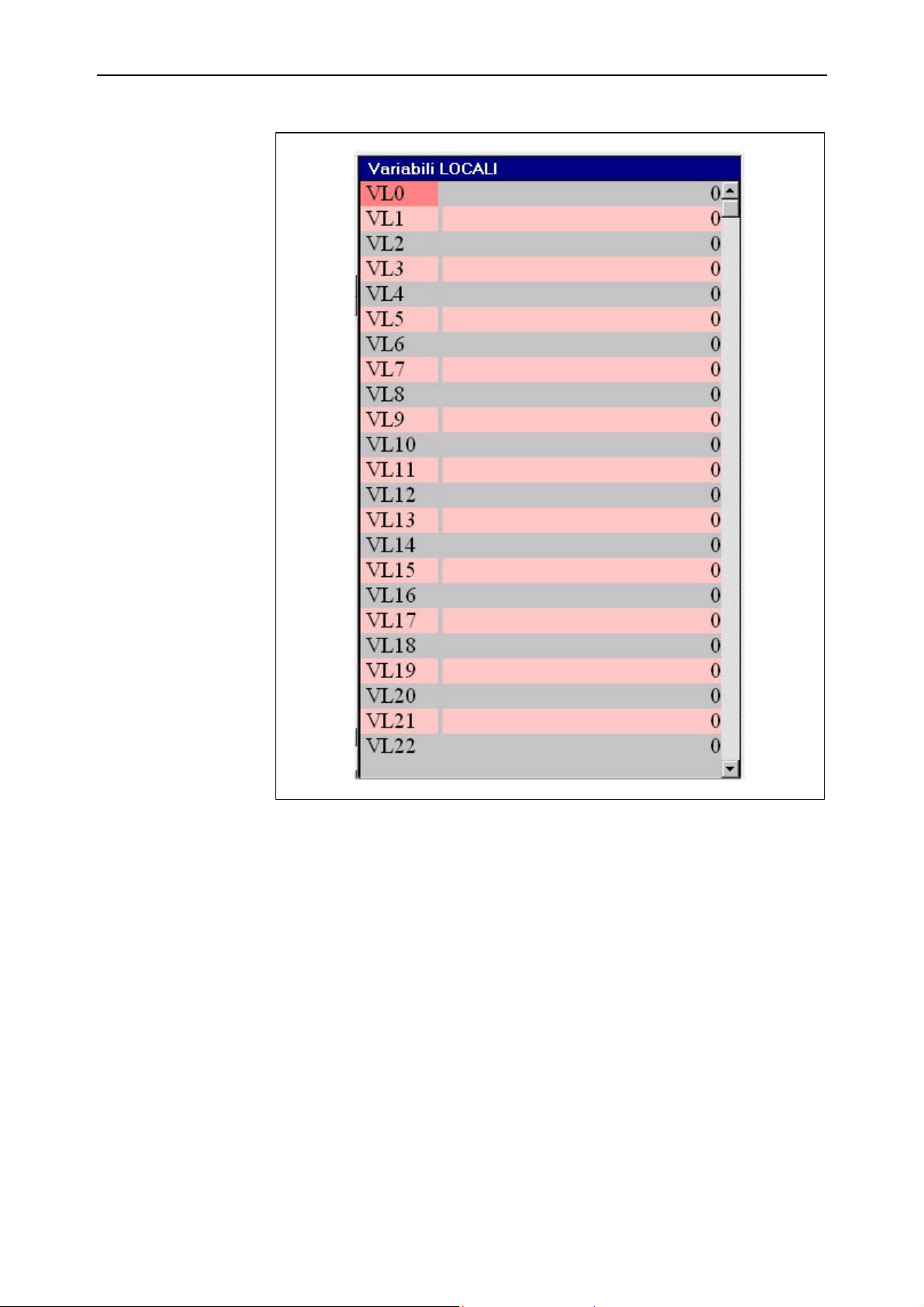
GO Channel monitor
Figura 6.3 -
The Local, Automatic and Globali variables can be displayed in this window.
On activation, the window proposes the list of local variables. Press [Automat.] to
display the automatic variables and then [Global] to display the global ones. Press
[Local] again to go back to the local variables displayed at the start. The key to press is
always the same as it is re-programmed each time with the function that allows access
to the next type of variables.
Deactivation
Use of the variables
window
Esa/Gv 91752.GO.0.GB 6.15
Press the [Mod/AUX Funct.] key to close the variables window.
After the variables window has been activated, use the arrow keys to select a variable.
Use the [Page Up] and [Page Down] keys to scroll through the pages of the table.
As will be noted, the current field is a different colour from the other fields.
Page 62
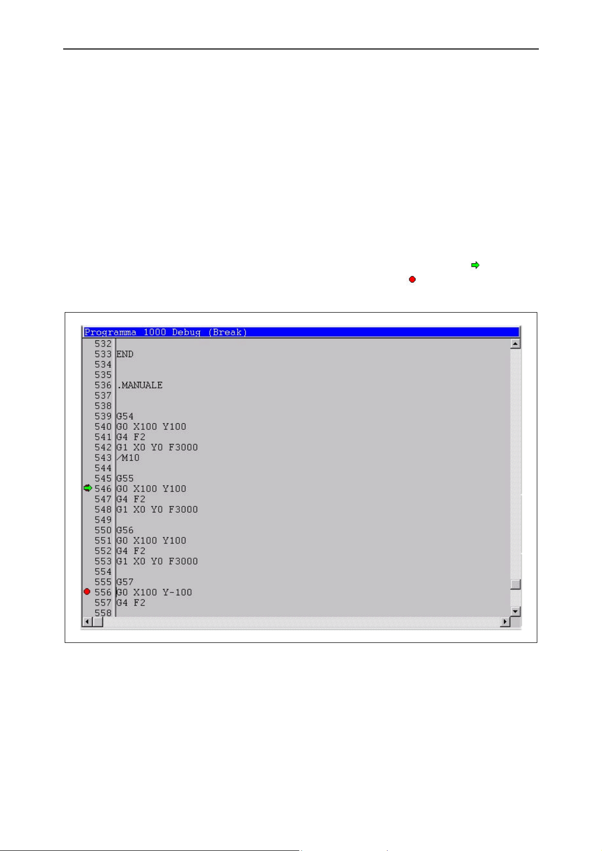
Channel monitor GO
The value of a variable can be modified by making the right-hand part of the variable
line the current field and digitizing the required value.
Thus successive accesses to the program in reading mode will take the newly modified
variable value into account.
6.6 Debug
The DEBUG function allows total control to be taken of the tested ISO program, the
more critical parts of which can then be checked.
When the debugger is used, the operator can enter breakpoints, execute the program
step by step and thus check the consistency of the variables in a precise point of the
program as well as checking to make sure that the program flow is correct.
Area [13] is subjected to small graphic modifications so as to display information
concerning the execution flow of the program. For instance, an arrow is introduced
to indicate the current line while a round symbol indicates the programmed
interruption points (breakpoints).
Activation
Figura 6.4 -
Press the [Debug] key to activate the debugger. The graphic aspect of the channel
monitor remains unchanged. Just the functions of the keys change as they are redefined in order to accomplish the debugging functions.
91752.GO.0.GB Esa/Gv6.16
Page 63

GO Channel monitor
Deactivation
Press the [Debug End] key to terminate the debugging session and go back to the
normal Channel Monitor functions. This action cancels all the programmed
breakpoints.
6.6.1 BreakPoint
A breakpoint is an instruction that stops the execution cycle. To associate a breakpoint
with an instruction means asking for execution to be suspended as soon as the CNC
encounters that instruction. Once execution has been stopped, the channel monitor user
can interact with the program execution by removing or inserting breakpoints,
checking or modifying variables or requesting step-by-step execution.
How to insert a
breakpoint
Breakpoint removal To remove a breakpoint, use the same sequence as used to insert it. When pressed on a
To insert a breakpoint, first select the required line using the directional arrows. The
cursor of area [13] is positioned as a consequence. Once the line has been reached,
press the [Breakpoint] key. The breakpoint symbol will be displayed alongside the
number of the selected line to indicate that the interruption point is activated.
If the program flow is such that that line is not executed, the inserted breakpoint will
never be able to interrupt program execution.
level with a line with a programmed breakpoint, the [Breakpoint] key will remove the
actual breakpoint itself.
To remove all the breakpoints in the program without repeating the canceling
procedure for each individual breakpoint, simply use the [Remove All Breakpoints]
key which will cancel all the programmed breakpoints.
Esa/Gv 91752.GO.0.GB 6.17
Page 64
Channel monitor GO
6.6.2 Step
Execution of a program in step mode is the same as entering a temporary breakpoint
on a level with the next instruction so that only the current line is executed, stopping
the execution on the next line.
Step-by-step execution of the program is obtained by means of input signals provided
by the PLC. This latter interfaces the step functions with the user.
The following step modes are tolerated:
Step Enables execution of the next program step. If a sub-program or
fixed cycle are encountered, they will be executed in atomic mode
without the debugger displaying the contents. This avoids
accessing the sub-program in debug mode.
Step In Same as Step, but if a sub-program or fixed cycle are encountered,
the next instruction executed is the first instruction of the subprogram. This means that step-by-step debug is executed within
the sub-program.
Step Out Executes the entire current sub-program code in atomic mode,
stopping on the first instruction after the current sub-program call.
This function is used to quit a sub-program and to continue with
step-by-step debugging in the calling program.
6.6.3 Display of symbolic variables
The debug function allows symbolic variables to be displayed, i.e. variables that require
a declaration in ISO mode.
Activation
This function is activated by pressing the [Watch] key. A window similar to the one
used to display the native variables is proposed.
91752.GO.0.GB Esa/Gv6.18
Page 65
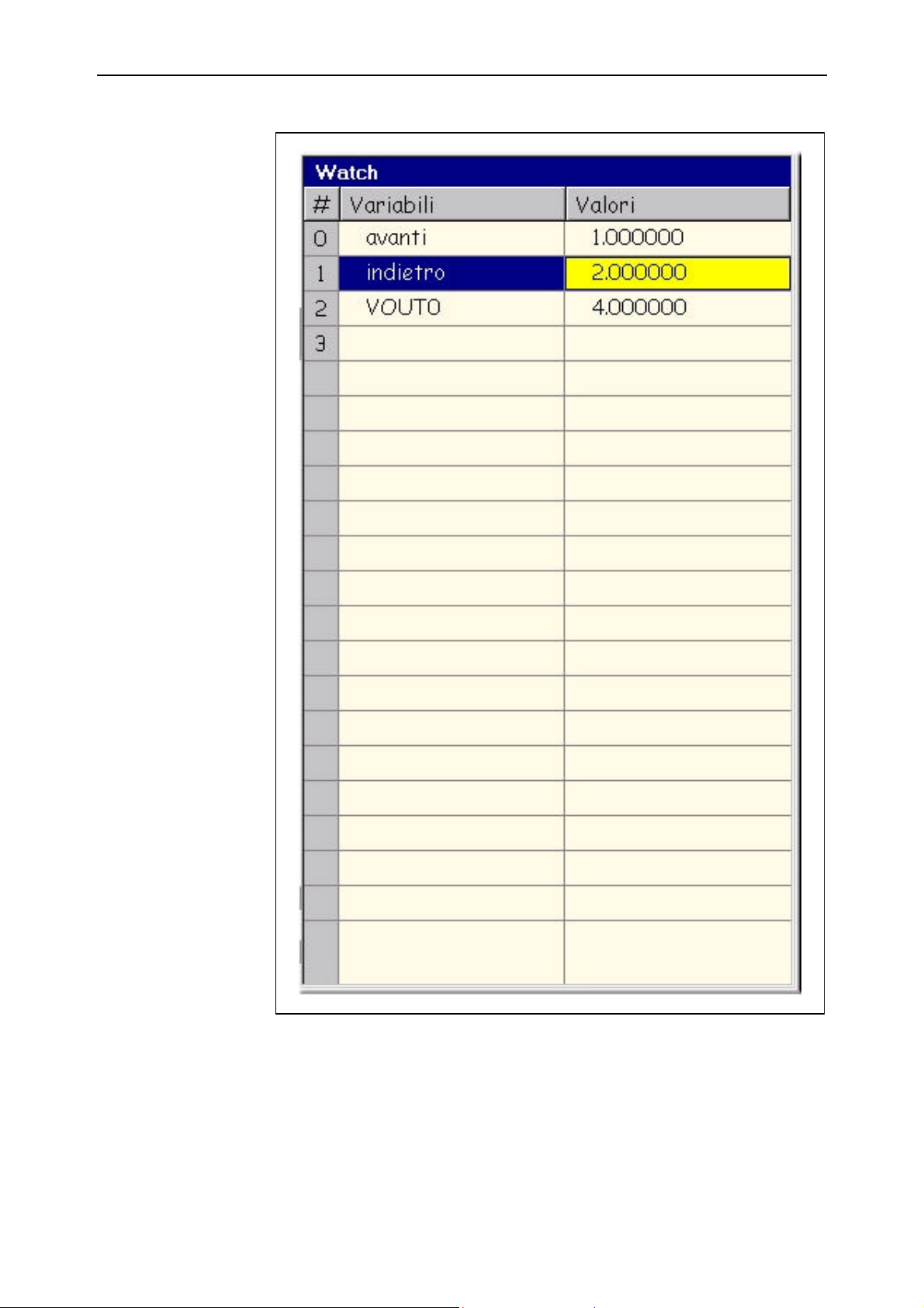
GO Channel monitor
Figura 6.5 -
Esa/Gv 91752.GO.0.GB 6.19
Page 66

Channel monitor GO
Deactivation
Selection of the
variable to display
Forcing Forcing a value means modifying the contents of a variable. This is of use if you
Press the [Watch] key again to close the variables display window. The list of variables
displayed will not be cancelled when this window is closed. It will be presented again
when the window is next opened. The list of variables will only be cancelled if the
debug status is quitted.
Initially, this table will be empty. Digitize the name of the variable to display.
The name must be entered in the left-hand part of the line while the value in the
variable will appear in the right-hand part of the same line. If the name of the variable
is wrong, the part that should hold the value will indicate the error with the Data not
existing! message.
Use the arrows to select the data entry field. The current field is the one in YELLOW.
discover that the result of a calculation is wrong (owing to a programming error) and
you wish to continue the debugging operation in the following lines. In this case, the
result can be corrected by forcing the value in the variable that contains it.
To do this, select the value to modify and digitize the new value. From this moment
onwards, the program will use the newly entered value for the subsequent calculations.
End of Chapter
91752.GO.0.GB Esa/Gv6.20
Page 67

GO ASCII Editor
7.1
7 ASCII Editor
7.1 Introduction
This tool is used to write or modify any file in text format that may be of use in
ensuring that the NC operates in the correct way. In particular, it is used to create or
modify:
ù ISO programs
ù ISO sub-programs
ù ISO Fixed Cycles
7.2 Activation
This editor is accessed from the BASIC MENU by pressing the [ASCII Editor] key.
New program The window heading bears the word **NEW** to show that a new file can be created.
The cursor is positioned on the first character of the editing window that is empty.
Each character of the file is digitized just like a standard editor.
How to select an
existing file
How to select the type
of file
Opening
Press [Open File] to open and thus modify an existing file. A selection window of the
file to open will appear.
Note that the displayed list of files is of the same kind as the type of file in the window
filter field. Change the filter selection if the type of file does not correspond to the type
required (use type *.* for a complete view of the contents of the current directory).
Press the button after having selected the required file.
Esa/Gv 91752.GO.0.GB
Page 68
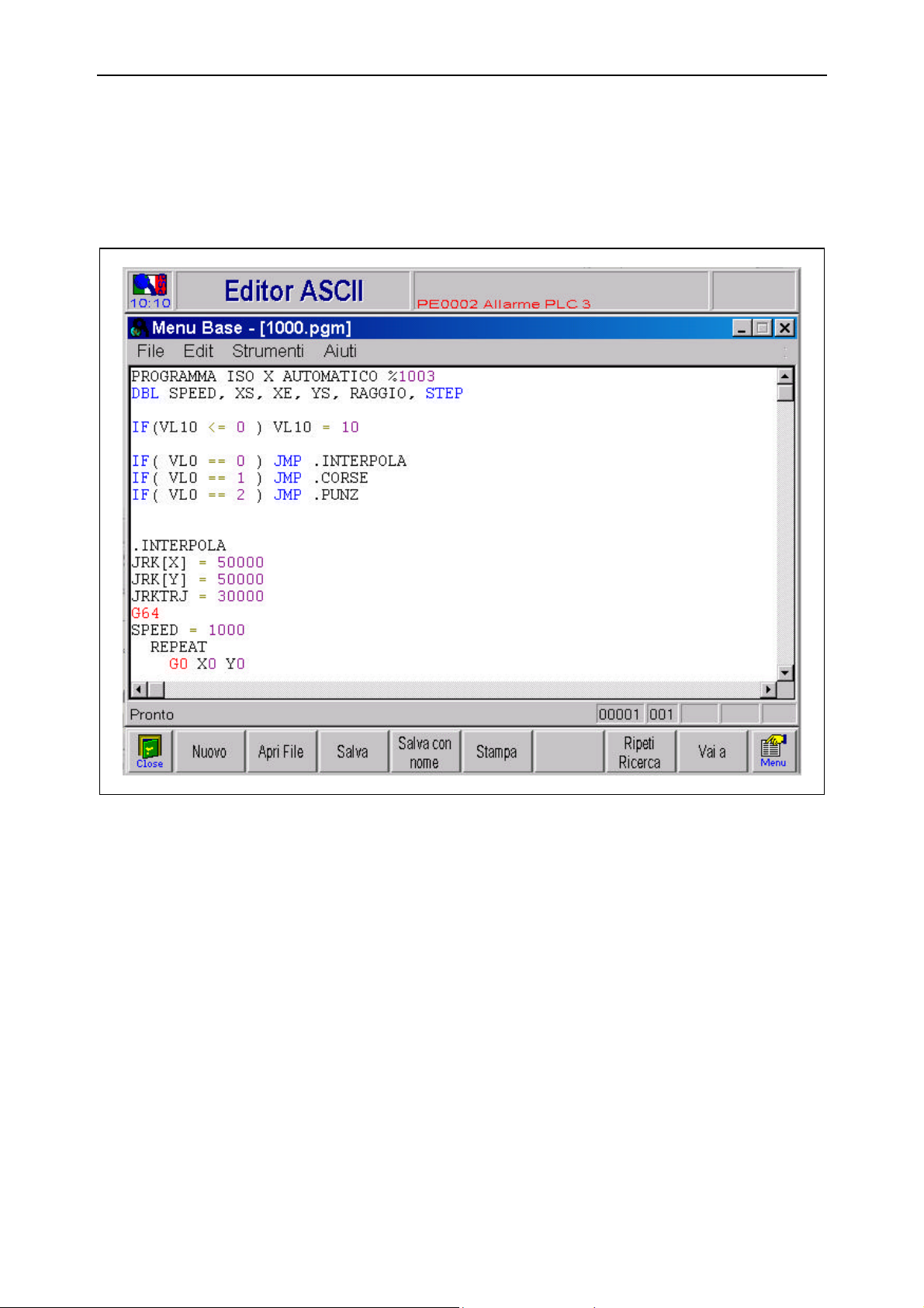
ASCII Editor GO
7.2
7.3 Description of the graphic interface
The ASCII editor is a free editor formed by a window that occupies the entire video
area, as shown in the figure:
Figure 7.1 –Free mode program writing area
It is divided vertically into two parts. The left-hand part (if enabled) displays the line
numbers while the right-hand part displays the program instructions.
Status Bar
Colour customizing The colours of the instructions allow the programming syntax to be recognized and
The status bar contains information about the line number and column on which the
cursor is positioned, and about the INSERT or OVERWRITE status selected with the
[Insert] key on the keyboard. In the first case, the digitized characters scroll
horizontally after the cursor. In the second case, the digitized characters overwrite the
ones to the right of the cursor.
made the program more legible.
The association of colours to parts of an instruction can be set-up by pressing the [Alt]
+ [S] > [O] keys.
The colour customizing window allows the operator to select:
91752.GO.0.GB Esa/Gv
Page 69
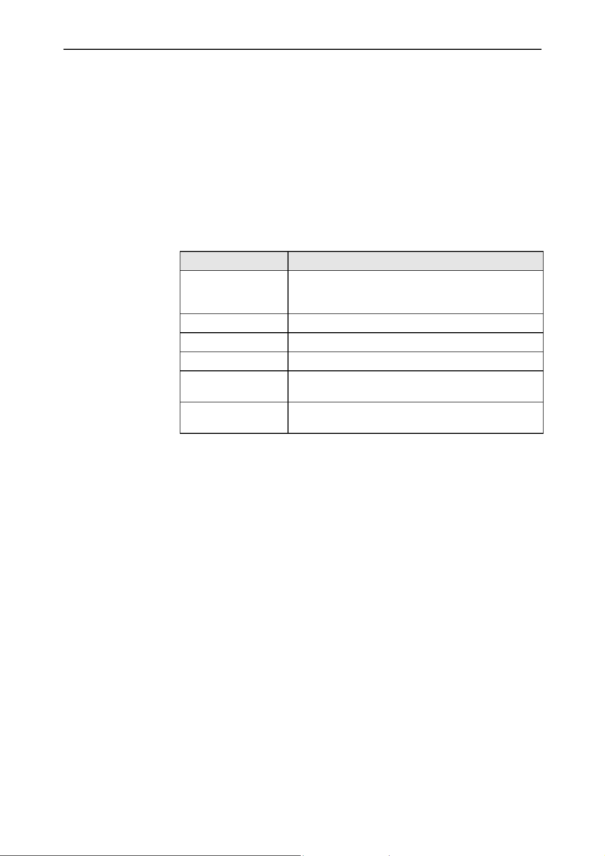
GO ASCII Editor
7.3
ù the colour of the text
ù the colour of the background
ù the type of character
ù the size of the character
ù boldface style
ù italics style
The text colour can be selected for each type of data item available while the remaining
properties are the same for all types of data provided by the editor.
The following types of data are available:
Type Description
Fixed Cycles Execution instruction codes. They begin with the letter G
and are followed by a number (0-999). They always appear
at the beginning of a line.
Numbers Numeric values; targets, angles, counters, etc.
Operators Characters recognized for algebraic calculations (+, *, -, /).
Keywords Parametric instructions.
Comments Portion of text that follows the “;” character, used to
describe the phases of the program.
Normal Names of variables, identifiers of the parameters or
instructions and references for jumps (labels).
7.3.1 ASCII Editor functions
Using the editor means digitizing each character that forms a file line.
This section describes the functions that facilitate file writing.
Line insertion To insert lines, move to the point of the program at which insertion begins, then
digitize all the characters that form the instruction.
The [ENTER] key creates an empty line above the current line.
Use the directional keys to move the cursor to the exact insertion point.
Characters can also be inserted into an already existing instruction in a similar way.
How to select a block
of lines
Move the cursor to the first line of the required block. Keep the [Shift] key depressed
while using the [↓↓] key to select the required block.
A block consists of at least one line.
Make sure that the cursor is correctly positioned. If it is not on the first character of a
line, the selection will include at least a portion of a line.
Line deletion
Esa/Gv 91752.GO.0.GB
Select the block of lines to cancel and press [Del].
Page 70

ASCII Editor GO
7.4
How to delete
characters
How to duplicate a
block of lines
Data search
Characters can be deleted by positioning the cursor to the left of the first character to
cancel and pressing [Del] for all the characters to cancel.
To duplicate a block of lines, select the required ones then press the [Ctrl] + [C] keys
(the lines will be memorized in the clipboard). Now position the cursor on the line
above the one where the block is to be inserted and press the [Ctrl] + [V] keys.
To search for a line portion, press the [Alt] + [E] > [T] keys and fill the search window
with the value to find. Now press [Enter].
The following options can be set in the search window:
Whole word If enabled, finds the entered value as a whole word
only and not as a portion of a word; e.g. a search for
“car” will not obtain a positive result if the word
“carpet” is encountered. The opposite will be obtained
if the option is disabled.
Capitals / lower case If enabled, checks whether the capitals and lower case
letters coincide with the search specifications; e.g. a
search for the word “mouse” will not obtain a positive
result if the word “Mouse” is encountered. The
opposite will be obtained if the option is disabled.
Direction Indicates the search direction within the program.
From the cursor position to the end of the program
(Down) or from the cursor position to the beginning of
the program (Up).
If the searched text appears several times in the file, press the [Repeat Search] key to
move to the next text occurrence.
Data substitution To substitute a portion of a line with another portion, press the Alt + E > U keys and
fill the substitution window with the value to find and the value with which it must be
substituted. Now press [Enter] to begin the substitution process.
The portion of line to substitute is highlighted and the substitution window allows one
of the following operations to be carried out:
Next Repeats the search without substituting the text shown.
Substitute Substitutes the text shown and proceeds with the
search.
Subst. All Makes all the substitutions through to the end of the
program without requiring further confirmation.
Annul Annuls the substitution operation and closes the
relative window.
91752.GO.0.GB Esa/Gv
Page 71

GO ASCII Editor
7.5
The following options can be selected in the search window:
Whole words If enabled, finds the entered value as a whole word
only and not as a portion of a word; e.g. a search for
“car” will not obtain a positive result if the word
“carpet” is encountered. The opposite will be obtained
if the option is disabled.
Capitals / lower case If enabled, checks whether the capitals and lower case
letters coincide with the search specifications; e.g. a
search for the word “mouse” will not obtain a positive
result if the word “Mouse” is encountered. The
opposite will be obtained if the option is disabled.
Line search
Annul change
Save changes to
program
To position the cursor on a known line, press the [Go to] key and enter the number of
the line to which the cursor must position, then press [Enter] to confirm the operation.
Press the [Ctrl] + [Z] keys to annul the last modification made.
Press the [Ctrl] + [S] keys to save the changes made to the program. If no name has
yet been given to the program (a new program saved for the first time), the operator
will be asked to specify one.
End of Chapter
Esa/Gv 91752.GO.0.GB
Page 72

ASCII Editor GO
7.6
91752.GO.0.GB Esa/Gv
Page 73

GO PLC Menu
8.1
8 PLC Menu
8.1 Introduction
The tool described in this charter provides the basic functions allowing a PLC to be
loaded and operated. This tool is not a substitute for WBLOC. It is just a small and
simple tool to use if WBLOC is not available, or for less expert users since it is simpler
than WBLOC.
This tool also includes diagnostic functions.
Activation
Press the [PLC Menu] from the BASIC MENU status to access the PLC Menu.
8.2 CNC diagnostics
The window of the PLC Menu is used by the NC firmware to display low level
information that can be useful in order to identify a bad CNC configuration.
This information is used by the ESA/GV assistance service or other personnel with
considerable experience, fully familiar with the CNC.
Error display
How to delete the
error list
Press the [Display Errors] key and the list of errors present will appear in the vacant
space in the mask.
The messages that appear here represent diagnostic information that the firmware of
the NC publishes in order to diagnose the operation of the machine in a better way.
Some of the messages do not concern malfunctions but simply diagnose potentially
incorrect settings (they should be considered Warnings) while other messages identify
configuration errors.
The Esa/Gv assistance staff could ask to see this list in order to check out a CNC fault.
Press the [Cancel Errors] key to delete the displayed list of errors. This function is of
use when checking whether modifications made to the configuration after errors have
been displayed have been beneficial. By canceling the errors and repeating the display,
the assistance staff can check whether the errors have been resolved or not.
Esa/Gv 91752.GO.0.GB
Page 74

PLC Menu GO
8.2
8.3 PLC functions
The PLC functions implemented in this tool are:
ù Current project loading
ù Start scanning
ù Stop scanning
Current project
loading
Start scanning PLC scanning must be carried out after a PLC upgrade or after scanning has been
Press the [Load PLC] key to activate a procedure that will carry out the following steps
in sequence:
1) Compilation of the source files of the current PLC
2) Transfer of the compiled files to the CNC
3) Loading of the transferred files into the memory
At the end of this sequence and if there are no errors in the PLC, the PLC program will
be transferred to the NC and loaded into the memory in block, i.e. the program
scanning function is not activated.
Current PLC means the PLC project referred by PlcProj under the AUTOSETUP
section in the Kvara.ini file. This PLC project is the same as the one loaded when the
AUTOSETUP function is executed.
After this operation, the report about the compilation and transfer result will appear in
the errors mask as also occurs with WBLOC.
intentionally interrupted by the person working on the CNC.
Press the [Start] key to activate the scanning phase. This key is only available if PLC
scanning has stopped.
PLC scanning cannot start unless the PLC has been loaded, thus after a compilation
error.
Stop scanning PLC scanning is interrupted automatically when an upgrade is being loaded, otherwise
it can only be interrupted intentionally by pressing the [Stop] key. This function is only
available if PLC scanning is being executed.
When PLC scanning stops, the PLC BLOCKED message appears.
91752.GO.0.GB Esa/Gv
Page 75

GO PLC Menu
8.3
8.4 Formatting the shared memory
Press the [Format Shared] key to format the shared memory. This operation must be
confirmed with [OK] when the confirmation request appears. If the [Format Shared]
key is pressed accidentally, just press [Annul] when the confirmation request appears
in order to annul the operation.
Shared memory formatting resets the shared memory of the CNC. This memory
contains both the machine parameters and the buffered RAM disks.
Following this function, the CNC will indicate CONFIGURATION NULL and it will
be necessary to repeat both the parameter loading and RAM DISK formatting
operations.
It is not common practice to format the shared memory. It must only be done when
explicitly indicated by the ESA/GV assistance service whose staff members will also
assist users in order to restore the operating conditions of the CNC.
End of Chapter
Esa/Gv 91752.GO.0.GB
Page 76

PLC Menu GO
8.4
91752.GO.0.GB Esa/Gv
Page 77

GO Autosetup
9.1
9 Autosetup
9.1 Introduction
The AUTOSETUP function allows all or part of the CNC firmware to be reprogrammed.
This function may only be used by specialized personnel familiar with the exact
procedure and informed about the risk they can incur if it is not carried out in the
correct way.
The AUTOSETUP procedure is fully automatic and very safe. If it fails to be
completed for some reason, it will stop the CNC in such a way that can only be
repaired by Esa/Gv.
The main causes for an AUTOSETUP failure are:
ù Voltage drop
ù Interruption in the communication caused by the user
When to use
AUTOSETUP
− Opening of the connection between the NC and PC (e.g. Disconnection of the
serial link)
− If the NC or PC are switched off
− Intentional forced interruption of BaseMenu
There are no other causes that can block an AUTOSETUP.
This is why it is strongly inadvisable to inexpert persons to carry out this procedure.
AUTOSETUP must be used when a CNC must be upgraded with a new version or
when specified by the Esa/Gv assistance service.
The end user of the machine need never carry out an AUTOSETUP.
Esa/Gv 91752.GO.0.GB
Page 78
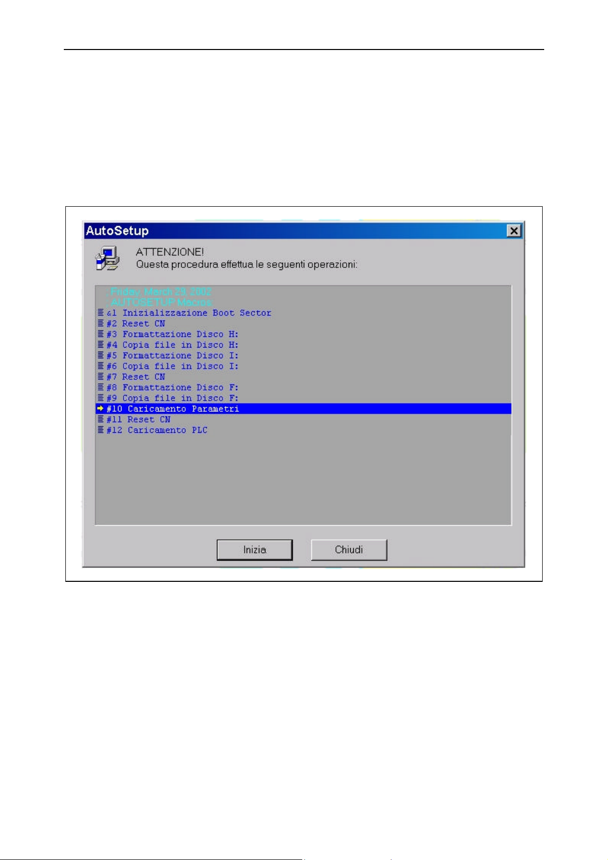
Autosetup GO
9.2
9.2 How AUTOSETUP functions
Activation Autosetup can be called up in automatic mode from BaseMenu on start-up if the
Autosetup.ini file is in the c:\Kvara directory.
Or it can be called up by pressing the [Autosetup] key from the BASIC MENU mask.
The Autosetup mask is accessed in both cases.
Figura 9.1 -
Now press the [Start] button to start the Autosetup process.
91752.GO.0.GB Esa/Gv
Page 79

GO Autosetup
9.3
Execution sequence The Autosetup mask displays the list of operations carried out in sequence:
1) BOOT SECTOR initializing.
2) NC reset.
3) Disk H formatting:
4) File copying into disk H:
5) Disk I formatting:
6) File copying into disk I:
7) NC reset.
8) Disk F formatting:
9) File copying into disk F:
10) Parameter loading.
11) NC reset.
12) PLC loading.
The files to transfer to the NC must have been loaded into the PC disk if the Autosetup
sequence is to function correctly.
Before beginning the Autosetup process, the starting point in the sequence can be
selected by moving the cursor (line in reverse) with the arrows to the first step to
execute.
Steps can also be excluded from the sequence, after which the operations required will
be displayed with these steps cancelled. This can help carry out a more reliable
AUTOSETUP sequence. The option can be selected by customizing the Autosetup.ini
file.
Deactivation The AUTOSETUP.INI file (if present) is cancelled at the end of this sequence so that
next time, BaseMenu starts in normal mode and BaseMenu closes automatically.
Press the [Close] button to bypass execution of the Autosetup sequence.
Interruption of
Autosetup
Once Autosetup has started, it cannot be interrupted. Forced interruption (using the
Windows Task Manager) is one of the main causes of damage to the NC. Thus, if
Autosetup is launched accidentally, it is advisable to allow it to terminate.
End of Chapter
Esa/Gv 91752.GO.0.GB
Page 80

Autosetup GO
9.4
91752.GO.0.GB Esa/Gv
Page 81
What do you think of this manual ?
We would be grateful for opinion about the following aspects of this manual:
Aspect in question Excellent Good Sufficient Insufficient Very bad
Ease with which the data can be consulted
Way in which the descriptions of the various
subjects are given
Completeness
Accuracy
Readability
Correctness of the terminology
Page layout
Number of illustrations
Quality of the illustrations
Please give us an evaluation of the overall quality of each chapter in the manual you have just consulted:
Chapter
number
Excellent Good Sufficient Insufficient Very bad
Please write the code of the manual in this space:
(the code is printed on the frontispiece)
Comments: _______________________________________________________________________________
_______________________________________________________________________________________
_______________________________________________________________________________________
_______________________________________________________________________________________
Write your address in the following space if you consider it necessary:
Name:_________________________________________________________________________________________________
Company: _____________________________________________________________________________________________
Address: ______________________________________________________________________________________________
Tel: ____________________________ Fax: ________________________________________________________________
Thanks for your help!
You can send this form via FAX, our number is +39-059-851313, or post it to our address: Esa-Gv - Ufficio
Documentazione Tecnica - 15 via Zamboni, Cp 43 - 41011 Campogalliano (Italy)
http://www.esagv.it - E-mail: [email protected]
Page 82

 Loading...