

ES TMX-589 User Manual
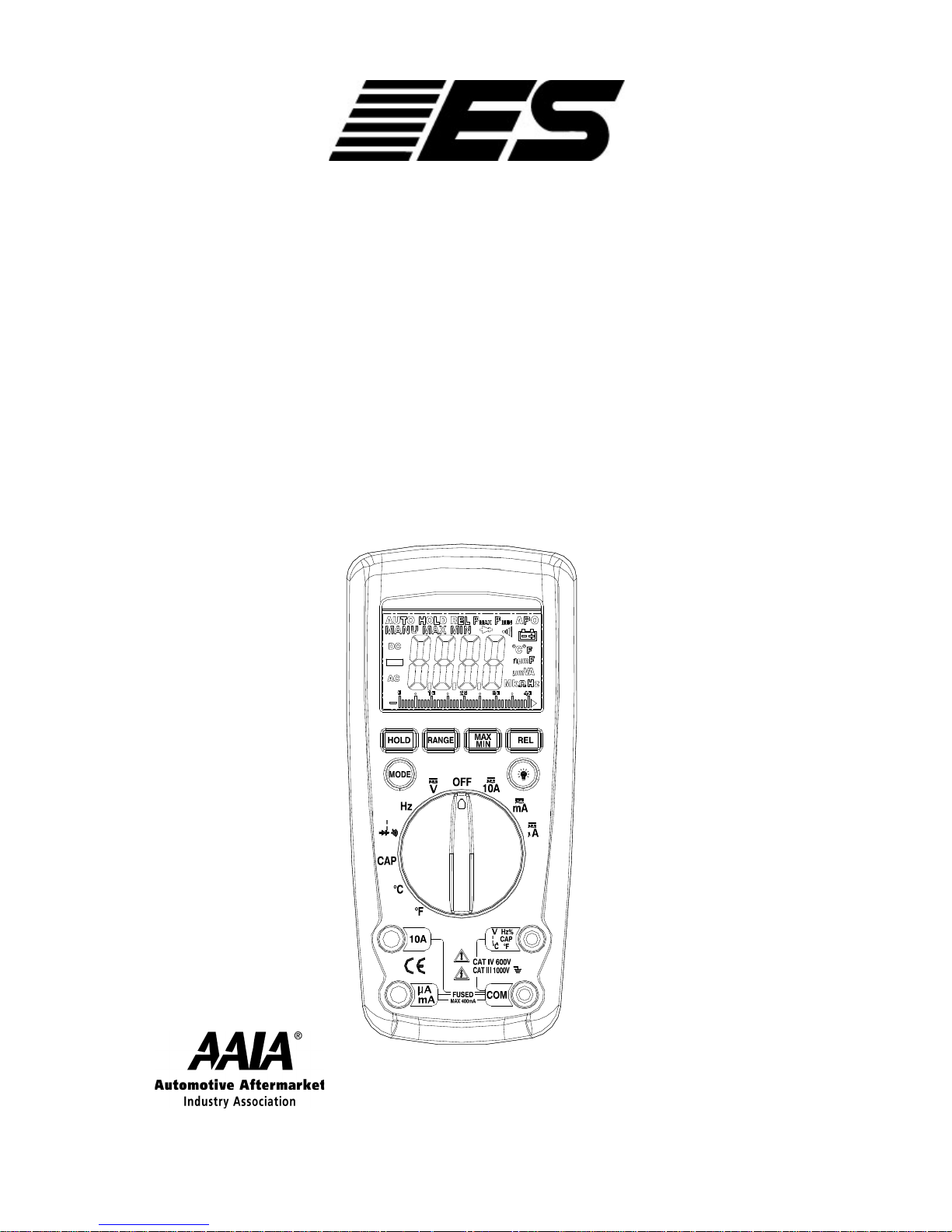
True RMS Auto/Industrial
Multimeter CATIII 1000V
Model TMX-589
User Manual
member

1
CONTENTS
Introduction ..……………………………………………………………… 2
Safety Symbols .……………………………………………………………2
Saftey Instructions ………………………………………………………3-4
Spare Parts List…………………………………………………………… 4
Controls & Jacks……………………………………………………………5
LCD Symbols……………………………………………………………….6
Push-button Functions……………………………………………..…7-8
Mode Button…………………………………………………………………7
Data Hold …………………………………………………………………. 7
Range Button…………………….…………………………………………7
Rel Button……...……………………………………………………………7
Max/Min Button …………………………………………………………….8
Back Light Button ………………………………………………………….8
Operating Functions…………………………………………………9-14
DC Voltage(V)…………………………………………………………….. 9
AC Voltage (V)………………………………………………………….. 10
Non-Contact AC Voltage (V)………………………………………….. 10
AC/DC Current (A)………………………………………………………. 11
Resistance (Ω)……………………………………………………………12
Audible Continuity ( )……………………………………………………12
Diode Check( )…………………………………………………………13
Capacitance(CAP) ……………………………………………………… 13
Temperature (℃/ 0F)
……………………………………………………..14
Frequency (Hz) …………………………………………………………...14
Maintenance…………………………………………………………..15-16
Battery Installation……………………………………………………….. 15
Replacing the Fuses…………………………………………………… 16
Specifications……………………………………………………… 17-21
Trouble Shooting………………………………………………………… 21
Warranty Information…………………………………………………… 22
2
Introduction
This meter measures AC/DC Voltage, AC/DC Current, Resistance,
Capacitance, Frequency (electrical & electronic), Duty Cycle,
Frequency, Diode Test, Continuity and Thermocouple Temperature.
Proper use and care of this meter will provide many years of reliable
service.
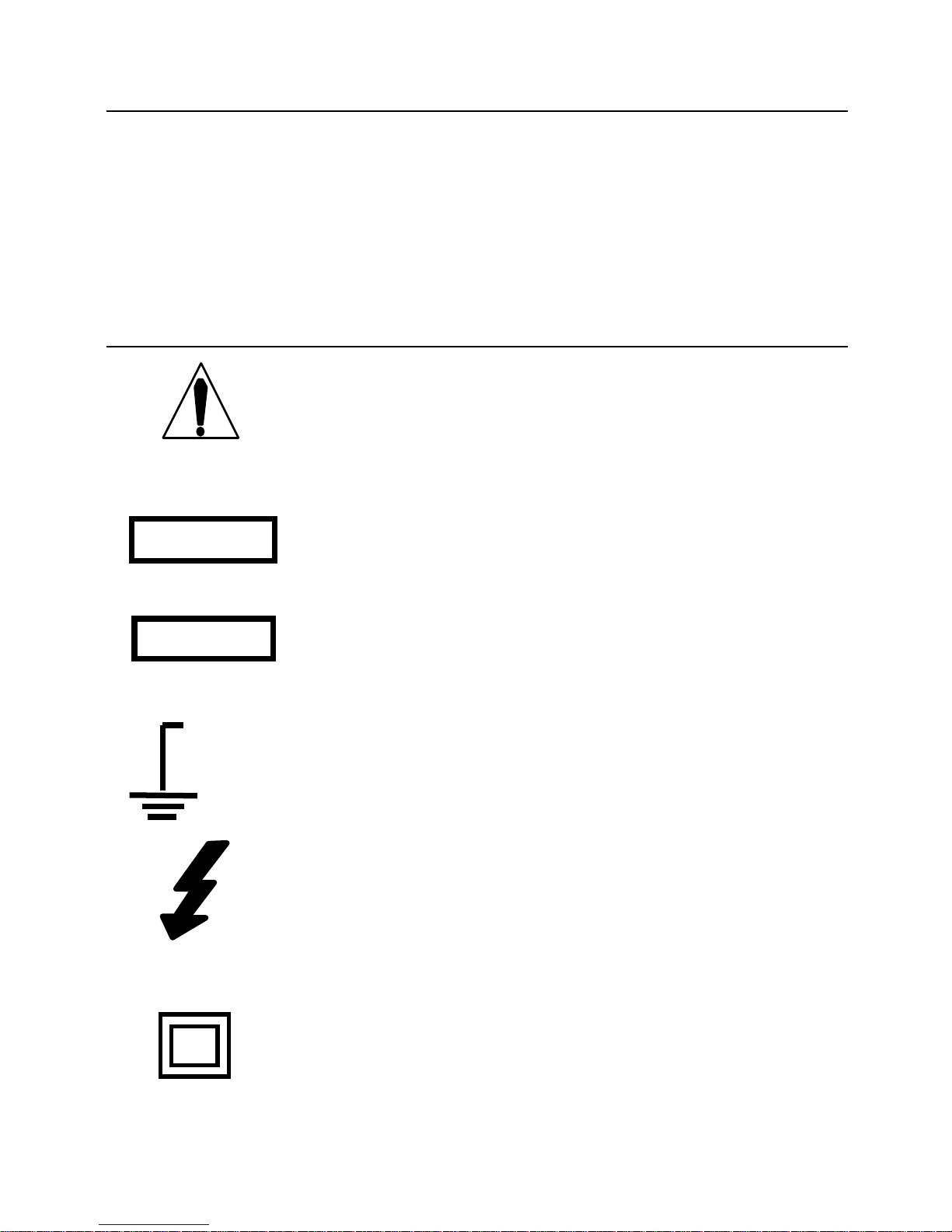
Safety Symbols
This symbol adjacent to another symbol, terminal
or operating device indicates that the operator
must refer to an explanation in the Operating
Instructions to avoid personal injury or damage to
the meter.
This WARNING symbol indicates a potentially
hazardous situation, which if not avoided, could
result in death or serious injury.
This CAUTION symbol indicates a potentially hazardous situation, which if not avoided, may result in
damage to the product.
This symbol advises the user that the terminal(s)
so marked must not be connected to a circuit point
at which the voltage with respect to earth ground
exceeds (in this case) 1000 VAC or VDC.
This symbol adjacent to one or more terminals
identifies them as being associated with ranges
that may, in normal use, be subjected to
particularly hazardous voltages. For maximum
safety, the meter and its test leads should not be
handled when these terminals are energized.
This symbol indicates that a device is protected
throughout by double insulation or reinforced
insulation.
WARNING
CAUTION
MAX
1000V

3
SAFETY INSTRUCTIONS
This meter has been designed for safe use, but must be operated with
caution. The rules listed below must be carefully followed for safe
operation.
1. NEVER apply voltage or current to the meter that exceeds the
specified maximum:
Input Protection Limits
Function
Maximum Input
V DC or V AC
1000VDC/AC rms
mA AC/DC
500mA 1000V fast acting fuse
A AC/DC
10A 1000V fast acting fuse (10A
for 30 seconds max every 15
minutes)
Frequency, Resistance,
Capacitance, Duty Cycle,
Diode Test, Continuity
1000VDC/AC rms
Temperature
1000VDC/AC rms
2. USE EXTREME CAUTION when working with high voltages.
3. DO NOT measure voltage if the voltage on the "COM" input jack
exceeds 1000V above earth ground.
4. NEVER connect the meter leads across a voltage source while the
function switch is in the current, resistance, or diode mode. Doing
so can damage the meter.
5. ALWAYS discharge filter capacitors in power supplies and
disconnect the power when making resistance or diode tests.

4
6. ALWAYS turn off the power and disconnect the test leads before
opening the covers to replace the fuse or batteries.
7. NEVER operate the meter unless the back cover and the battery
and fuse covers are in place and fastened securely.
If the equipment is used in a manner not specified by the
manufacturer, the protection provided by the equipment may be
impaired.
NOTE: Ghost Voltage - On some low AC and DC voltage ranges, with
the test leads not connected to a device, the display may show a
random, changing reading. This is normal and is caused by the highinput sensitivity. The reading will stabilize and give a proper
measurement when connected to a circuit.
SPARE PARTS LIST
#608 Replacement Test Leads CATIII 1000V
#637 Replacement Temperature Probe Bead Style
#671 Replacement Fuse 10A – 1000V
#672 Replacement Fuse 0.5A – 1000V
For other spare parts, please call 800-227-1603 or email your request
to info@esitest.com.
5
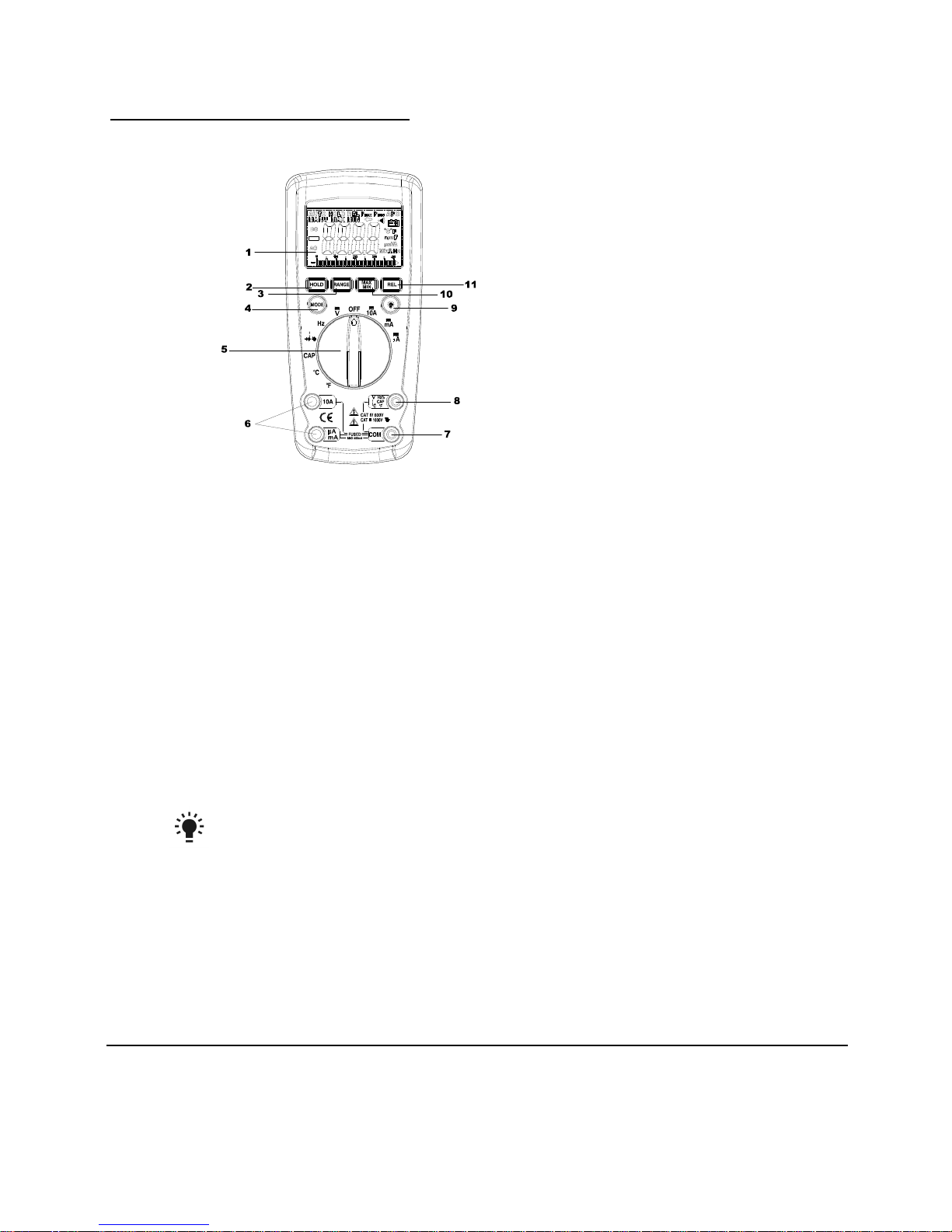
CONTROLS AND JACKS
1.
4,000 count LCD display
2. HOLD button
3. RANGE button
4. MODE button
5. Function switch
6. mA/µA and 10A input jacks
7. COM input jack
8. Positive input jack
9. Backlight button
10. MAX/MIN button
11. REL button
NOTE: Tilt stand and battery compartment are on rear of unit.
6
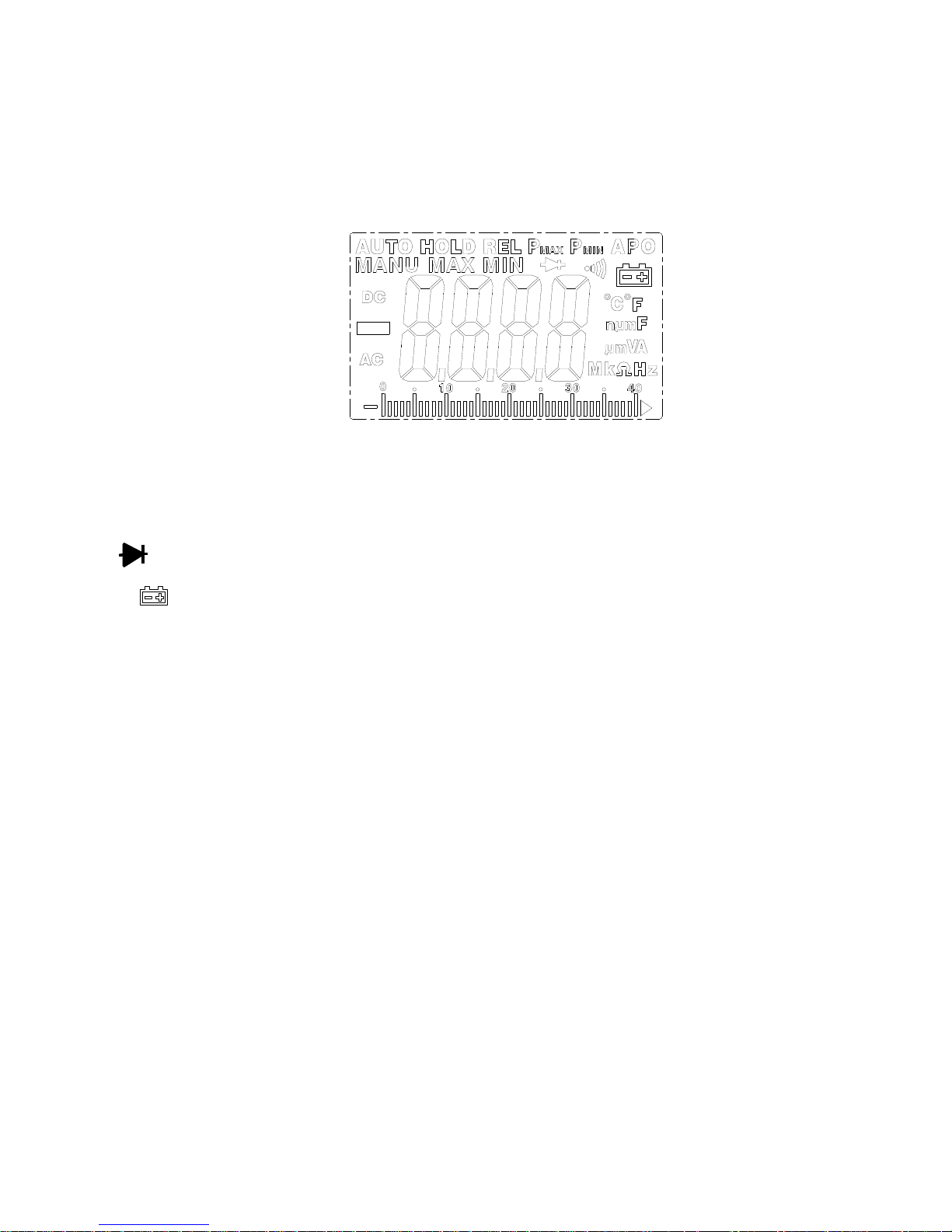
LCD SYMBOLS
•))) Continuity
Diode test
Battery status
n Nano (10-9) (capacitance)
µ Micro (10-6) (amps, cap)
m Milli (10-3) (volts, amps)
A Amps
k Kilo (103) (ohms)
F Farads (capacitance)
M Mega (106) (ohms)
Ω Ohms
Hz Hertz (frequency)
REL Relative
V Volts
AC Alternating current
DC Direct current
ºF Degrees Fahrenheit ºC Degrees Centigrade
MAX Maximum MIN Minimum
AUTO Auto-Range APO Auto Power-Off
HOLD Display hold
 Loading...