

ES FCW 12.1, FCW 18.1 Operation & Installation Manual
Wall mounted Fan Coil
Operation&Installation manual
◎ Before operating this product,please read the instruction
carefully and keep this manual for future use.
1.
3. Working principle
4. Specification
5. Installation
5.1 Location
5.2 Mounting plate installation
5.3 Installing the unit onto the mounting plate
5.4 Piping and drainage
5.5 Air purging
6. Remote controller operation
7. Functions & operation modes
8. Trouble shooting
8.1 Display
8.2 Failure Code
8.3 Causes&Action
9. Maintenance
10. Exploded view
11. Wiring diagram
Names of Components
2. Notice
1
2
2
3
4
5
5
5
6
7
8
10
11
14
14
14
15
16
17
CONTENT
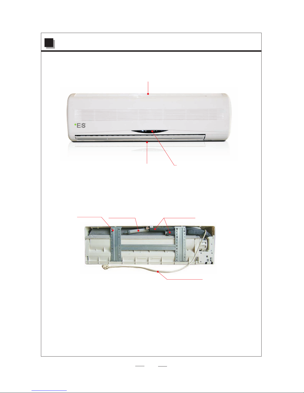
Display
Air outlet
Air inlet
Wate r Pipe
Drain hose
Mounting
plate
Power plug
1. Names of Components
1
● The unit is wid ely used together with centr al HVAC s ystem in hotel, h ospital, me dicine
factory, theater, commer cial building , office bu ilding, ent erprises, che mical industry, exhibit ion
room, resea rch institutes and so on.
● The install ation, commissioning and m aintenance of t hese machin es should be perf ormed by
qualified p ersonnel having a good knowl edge of standar ds and local regulations, as w ell as
experienc e of this type of equipment.
● Make sure tha t the rated voltage of the unit co rresponds to th at of the name plate before
commencin g wiring work according to the w iring diagram .
● The unit must b e GROUNDED to pre vent possib le hazard due to in sulation failure.
● Make sure tha t the unit has been switched OFF b efore install ing or servicing the unit.
● Keep the unit a way from any combustible or co rrosive envir onment.
● Disconnec t the power plug wh en the fan coil i s not going to be use d for a long time.
Otherwise d irt may gather and cause low efficiency .
● Make sure the a ir inlets and outlets of the uni t are not blocked .
2. Notice
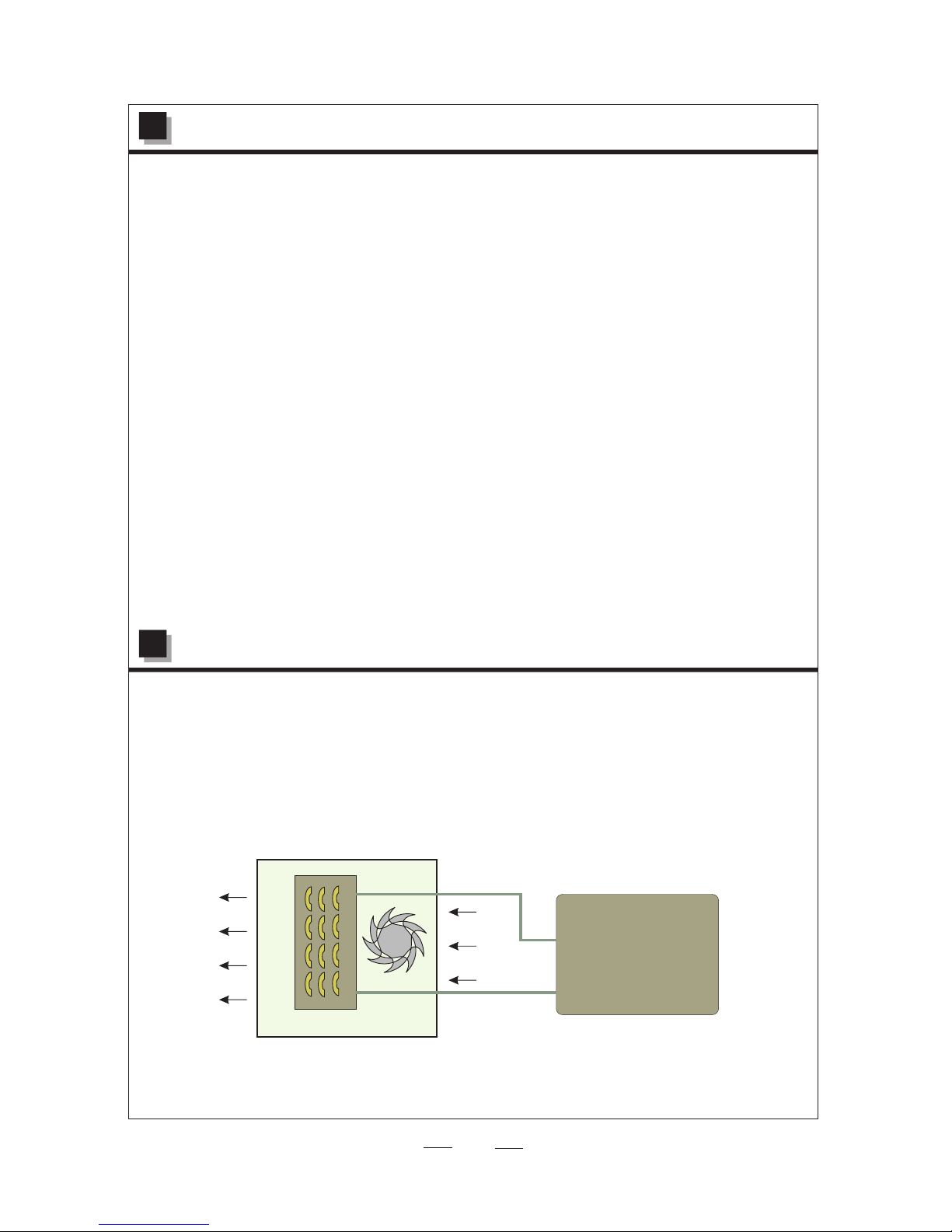
Air inlet
Air outlet
Heat Exchan ger
Fan Coil
The fan c oil unit has no ene rgy by itse lf but provides heating or coo ling with hot or ch illed water from
central wat er supply syste m(heat pump o r chiller etc) .The fan of the unit blows throug h the heat
exchanger t o cool or heat the air in the room.
If inlet wate r is cool, set the unit to cooling m ode, the air outl et is cool air.
If inlet wate r is hot, set the unit to heating mo de, the air outle t is hot air.
The uni t is characteri zed with energy-saving, high efficiency, lo w noise, reliab le and
convenien t to select and install.
Fan
Central wat er
supply syst em
3. Working principle
2
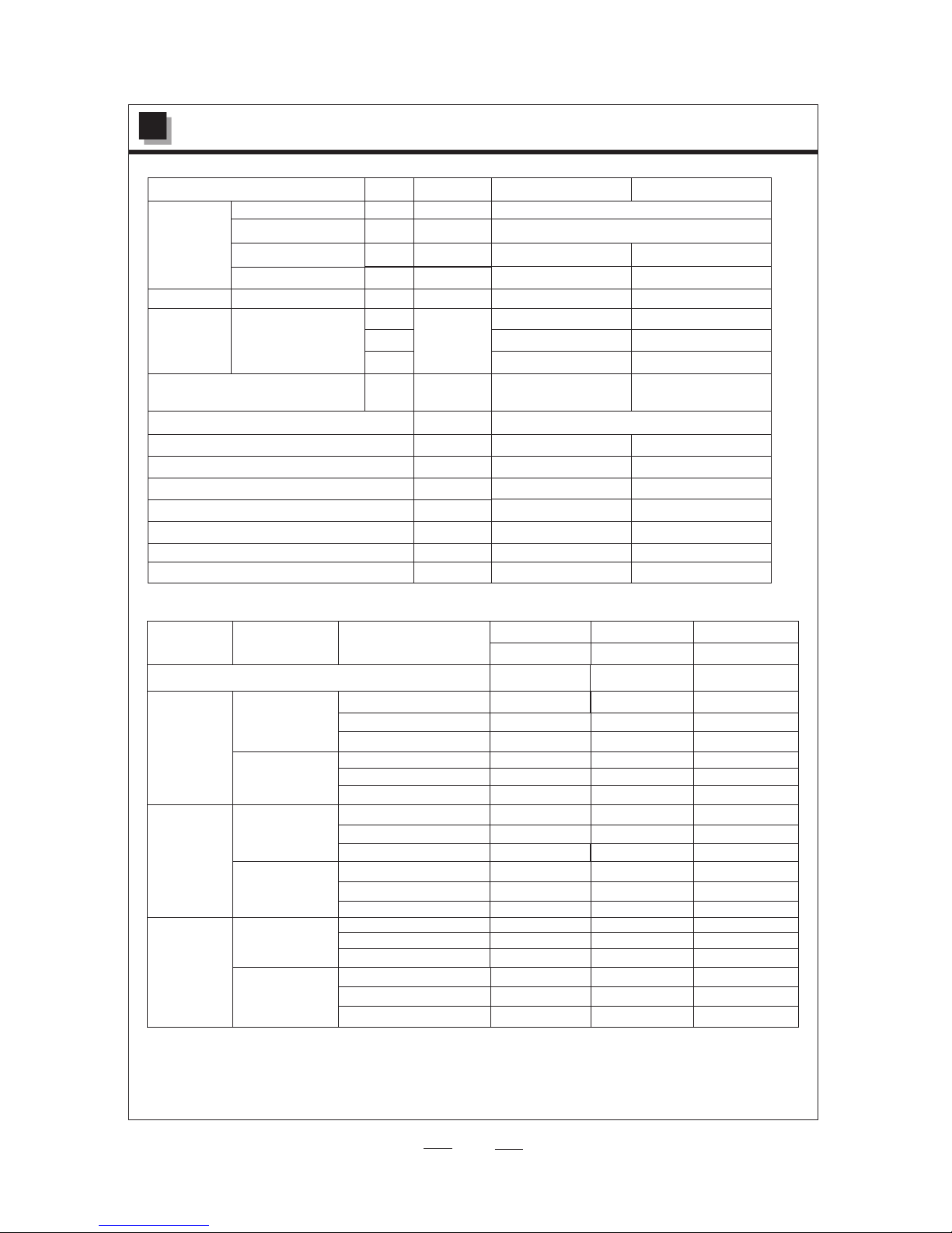
3. Specification
3
Model
Coil data
Tub e diameter
Rows/fins
Fin height/ length
Face area
mm
mm
W
m2
RPM
m3/h
W
dB(A)
mm
mm
mm
Kg
Net Weight
Packaging D imension (L×D ×H)
Net Dimensi on (L×D×H)
Drain Conne ction--(O.D )
Pipe Connec tor Size
Noise Level a t high speed
Power Input
Power Suppl y
Air Flow at Hig h Speed
Fan data
Motor data
Fan Speed
Power Outpu t
L
M
H
1100 (cooling)
1150 (heating)
15
1070×377×262
1020×315×210
16
G1/2
37
72
35
35
G3/8
13
890×280×210
950×345×260
12
650 (coolin g)
750 (heatin g)
220~ 20/5 0,60Hz/1PH
1000
1100
1300
35
0.25
310×796
0.092
15
1150
1000
800
2R/17fin
7
FCW 18. 1
FCW 12. 1
31×561
Output Under Different Water Temperature
FCW 12. 1
Fan Speed
Work ing Mode
Wate r Inlet Temp (℃)
FCW 18. 1
FCW 12. 1
Capacity(W)
Capacity(W)
Capacity(W)
Wate r Flow Rate(L/S )/Water Pressure Dr op(Kpa)
Low Speed
Medium
Speed
High Speed
Cooling
Heating
Cooling
Heating
Cooling
Heating
Note: (1) Cap acity Test Conditio n for cooling : room temperat ure is DB/WB 27/19℃ .
Capacity Test Con dition for heat ing: room tem perature is DB/ WB 20/-℃ .
(2) specifica tions are subject to change wi thout prior not ice. For actual pecificati ons
of unit, plea se refer to the stickers on the un it.
The
5
7
9
60
50
45
5
7
9
60
50
45
5
7
9
60
50
45
3100
3540
4490
1112
1365
1530
3160
3660
4600
1120
1375
1545
3260
3710
4640
1130
1390
1670
0.062/30
0.076/40
0.13/40
2025
1785
1510
5160
4000
3440
2010
1730
1470
5020
3920
3340
1990
1685
1460
4890
3870
3100
3660
3375
2685
7365
5775
4830
3455
3225
2530
7220
5625
4575
3420
3035
2510
6710
5225
4390
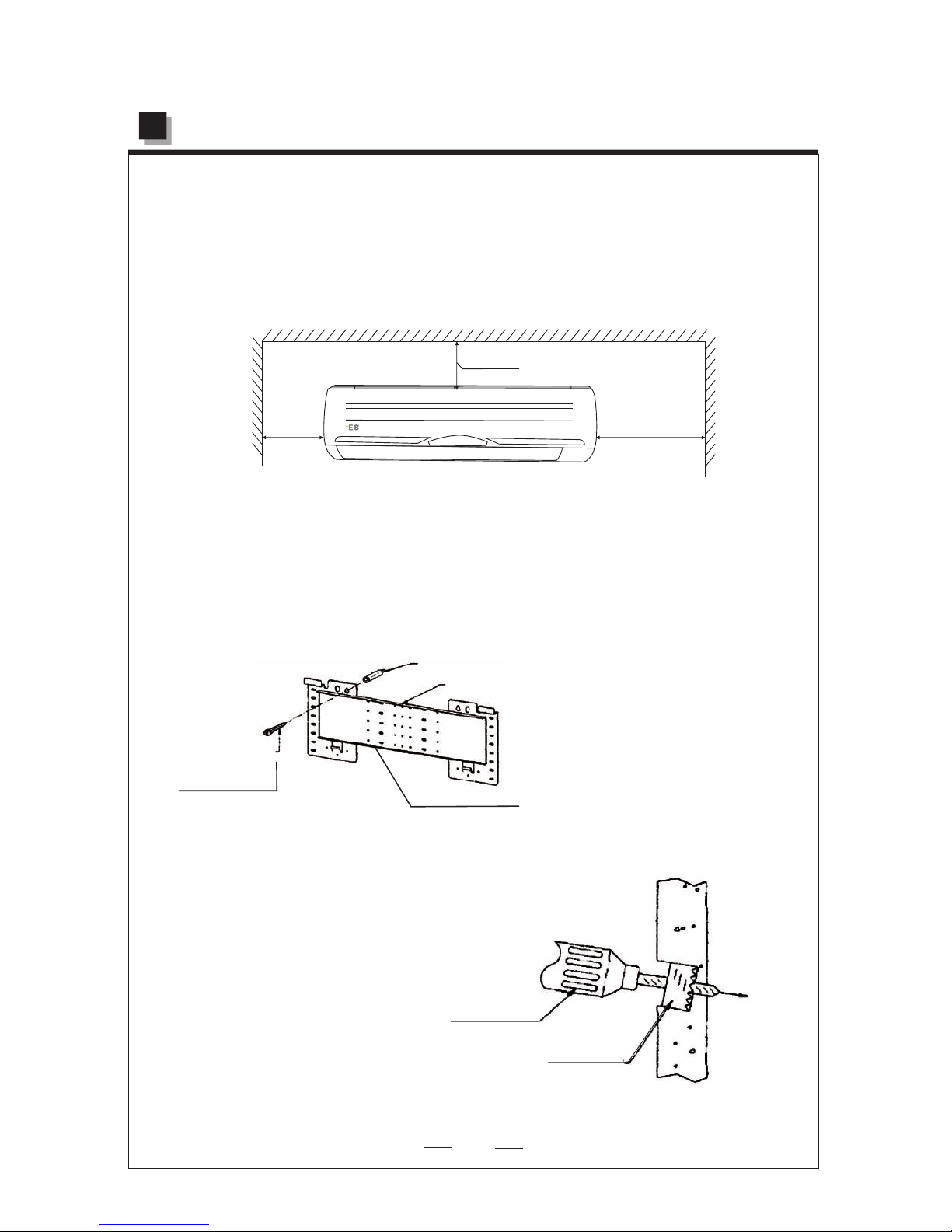
Select installation location with following considerations;
1. The re turn and supply a ir should be free f rom any obstr uction.
2. The wa ll which the unit i s to be mounted on should be stiff enough not t o resonate and
produce muc h noise.
3. Ensure the c learance on every side of the un it conforms to fi gures as shown be low.
5.1 Location
>2 00 mm
>2 00 mm
>4 00 mm
5.2 Mounting plate installation
5. Installation
1. After selecting a proper l ocation, plac e the mountin g plate horizon tally onto the wa ll.
Use a plumb lin e if necessary.
2. Drill the ho les for the type of mounting scr ew to be used. Chec k local building regulatio n for
correct mou nting screw.
3. Secure the m ounting plate and check for if i t is stable.
Mounting pl ate
▲Figure 1
Long screw
In door
Slightly sl ant
Outdoor
Drilling
machine
Hole saw
Wall
Indoor
▲Figure 2
4. Drill a hole of 70.0 mm in
Diameter for piping either at
the right or left side of the unit
and make sure that the hole is
slightly slant downward.
4
Wall p lug
 Loading...