

ES AWH9-V5+, AWH11-V5+ User Manual
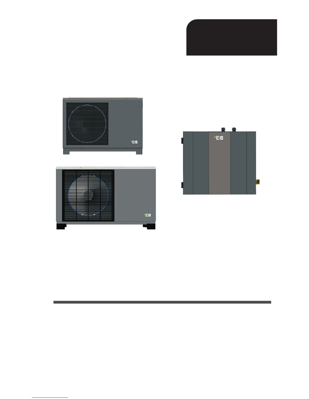
Heat Pump
DC Inverter Air to Water
Before operating this product, please read the
instructions carefully and keep this manual for future use.
User’s manual
User’s manual
AWH9/11-V5+
MBG series

2

1. Before use
1.1 Safety precautions
1.2 Working principle
1.3 Main components
1.4 Specifications
2. Installation
2.2 Tools needed
2.3 Installation of the indoor control unit
2.4 Installation of the monoblock unit
2.5 Accessories
2.6 Wiring
2.7
2.8
2.9
3. Usage
3.1 Introduction of wired controller
3.2 Parameter setting overview
3.6
4. Maintenance
4.1 Attention
4.5
4.6
4.7
4.8 Trouble-shooting
5.
5.1 Outlines and dimensions
5.2 Exploded view
5.3 Wiring diagram
2.1 General application system introduction
Installation of safety valve kit
3.3 Basic operation
4.2 Cleaning of water filter
4.3 Cleaning of plate heat exchanger
4.4 Gas charging
Condenser coil
Service of indoor control unit
Service of monoblock unit
Water pipe connection
Test run
3.4 Advanced setting
3.5 Failure code
Error code
Attached drawing
4
4
6
7
8
11
11
13
13
15
17
18
25
26
27
28
28
30
35
47
58
59
68
68
68
68
68
69
69
72
76
78
78
81
83
Catalogue
3
1. Before use
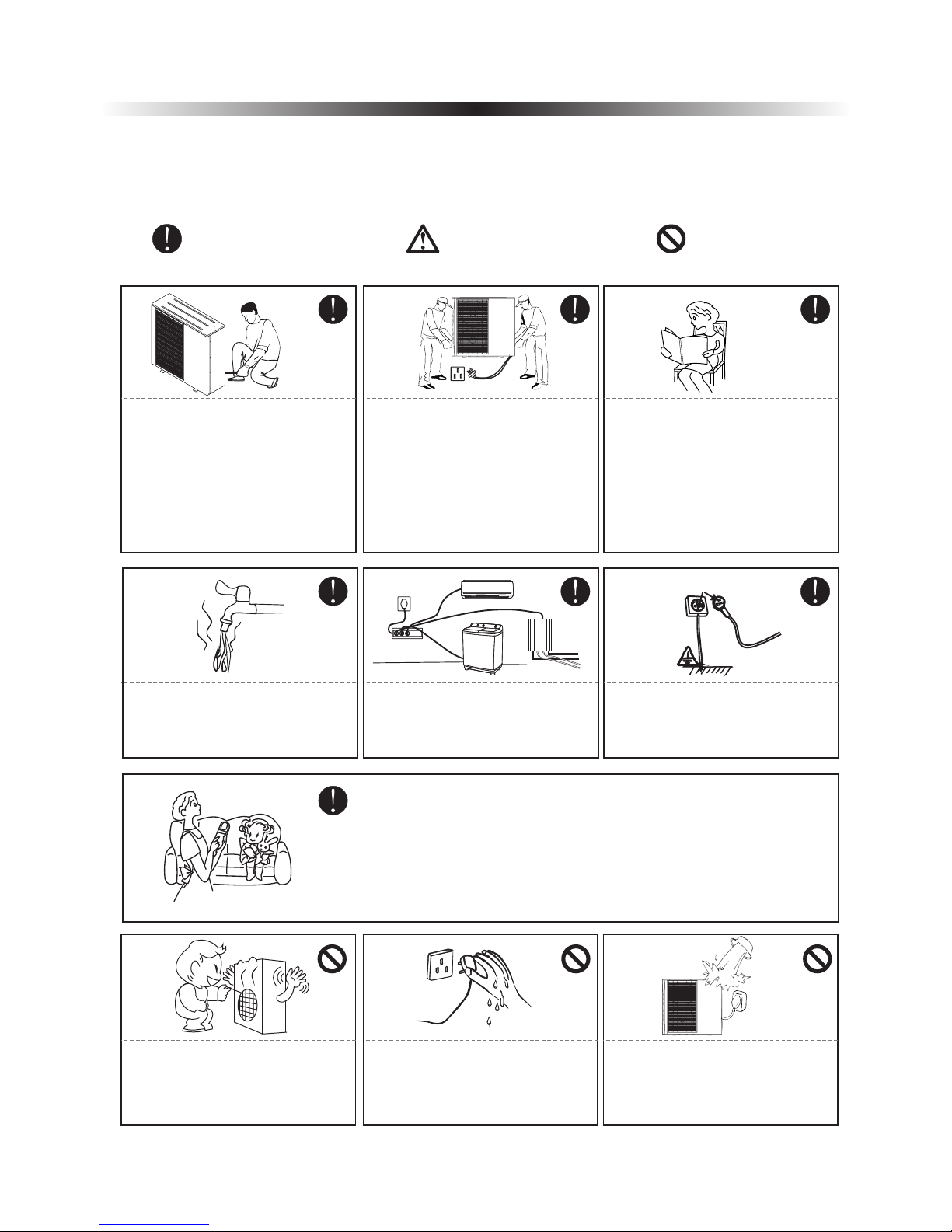
CautionWarning
Prohibition
1.1 Safety precautions
The following symbols are very important. Please be sure to understand their meaning, which concerns
the product and your personal safety.
The installation, dismantlement
and maintenance of the unit must
be performed by qualified
personnel. It is forbidden to do any
changes to the structure of the unit.
Otherwise injury of person or unit
damage might happen.
To avoid electrical shock, make
sure to disconnect the power
supply 1 minute or more before
servicing the electrical parts. Even
after 1 minute, always measure the
voltage at the terminals of main
circuit capacitors or electrical parts
and, before touching, make sure
that those voltages are lower
than the safety voltage.
User Ma nual
Be sure to read this manual before
use.
For sanitary hot water, please
always add a mixture valve before
water tap and set it to proper
temperature.
Ground wire
Use a dedicated socket for this
unit, otherwise malfunction may
occur.
The power supply to the unit must
be grounded.
Do not touch the air outlet grill
when fan motor is running.
Do not touch the power plug with
wet hands. Never pull out the plug
by pulling the power cable.
Water or any kind of liquid is
strictly forbidden to be poured into
the product, or may cause electric
creepage or breakdown of the
product.
This appliance can be used by children aged from 8 years and above
and persons with reduced physical, sensory or mental capabilities or
lack of experience and knowledge if they have been given supervision
or instruction concerning use of the appliance in a safe way and
understand the hazards involved. Children shall not play with the
appliance. Cleaning and user maintenance shall not be made by
children without supervision.
4
1. Before use
Copper
Steel
Fuse
Main
Power Cable
RCD
Indoor
control
unit
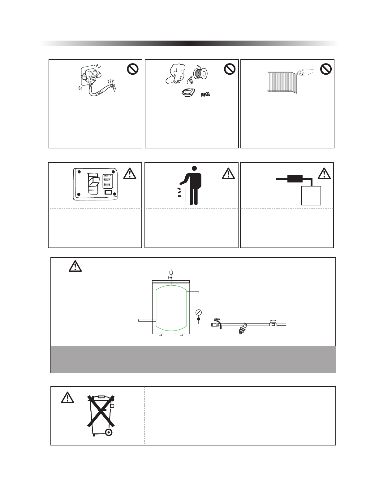
When the power cord gets loose
or damaged, always get a qualified
person to fix it.
It is mandatory to use a suitable
circuit breaker for the heat pump
and make sure the power supply to
the unit corresponds to the
specifications. Otherwise the unit
might be damaged.
Disposal of Scrap Batteries(if
there is).Please discard the
batteries as sorted municipal waste
at the accessible collection point.
Installation of a residual current
device (RCD) having a rated
residual operating current not
exceeding 30 mA is advisable.
ON
OFF
Please select the correct fuse or
breaker as per recommended. Steel
wire or copper wire cannot be
taken as substitute for fuse or
breaker. Otherwise, damages
maybe caused.
Be aware fingers might be hurt by
the fin of the coil.
5
This marking indicates that this product should not be disposed with
other household wastes throughout the EU. To prevent possible harm to
the environment or human health from uncontrolled waste disposal,
recycle it responsibly to promote the sustainable reuse of material
resources. To return your used device, please use the return and
collection systems or contact the retailer where the product was
purchased. They can take this product for environmental safe recycling.
System water filling
T/P valve
Connect to heating/cooling system
Buffer tank
Connect to heat pump
One way valve
Filter
City water inlet
1. It's suggested to use pure water for filling the system.
2. If use city water for filling, please soften the water and add a filter.
Note: After filling, the system of water system should be 0.15~0.6MPa.
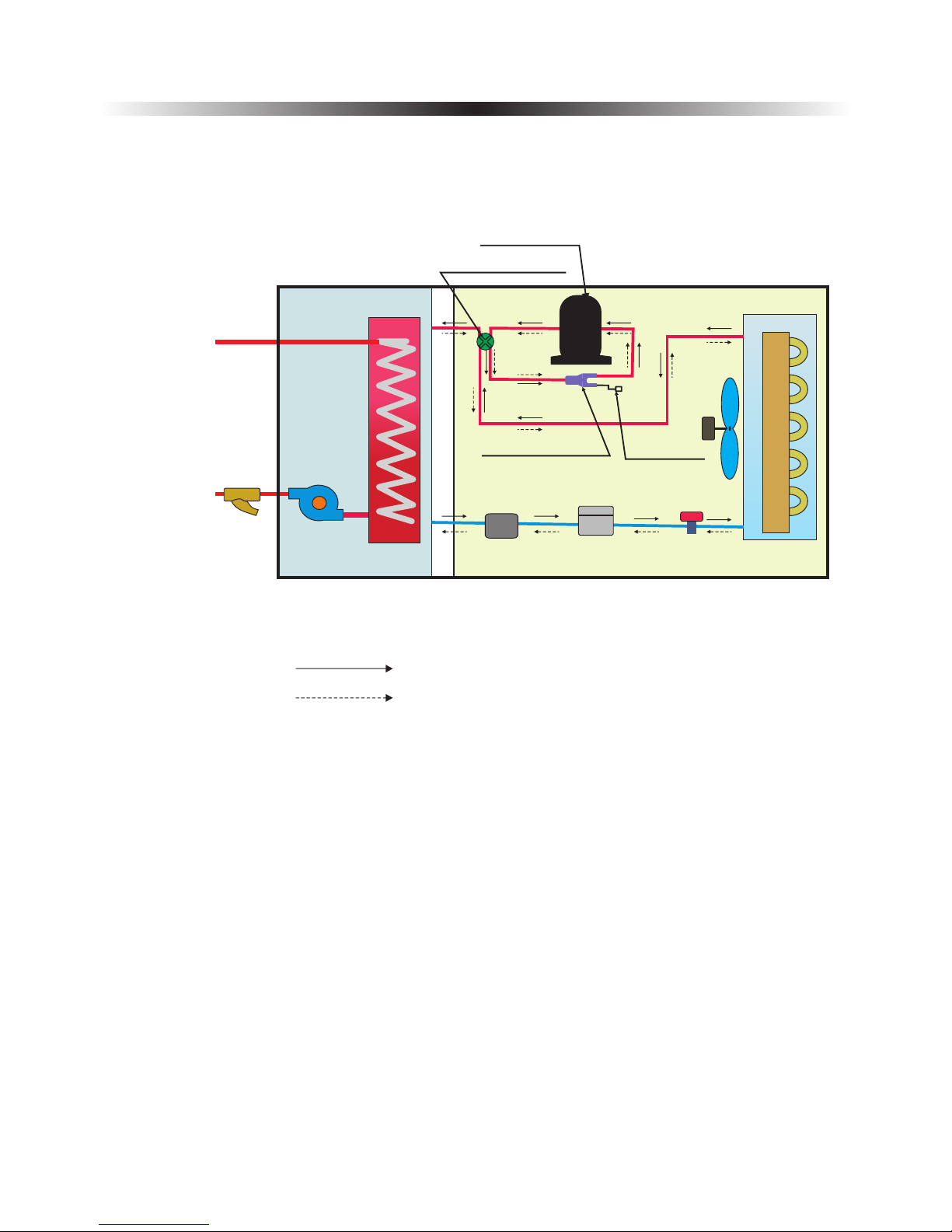
1.2 Working principle
1. Before use
Water inlet
Water Outlet
Filter
Water pump
Heat
exchanger
Power supply
Four-way vavle
Compressor
Three-way valve
Refrigerant Filter
T-connector
Fan motor
Pressure
check valve
Evaporator
Heating
Cooling
6
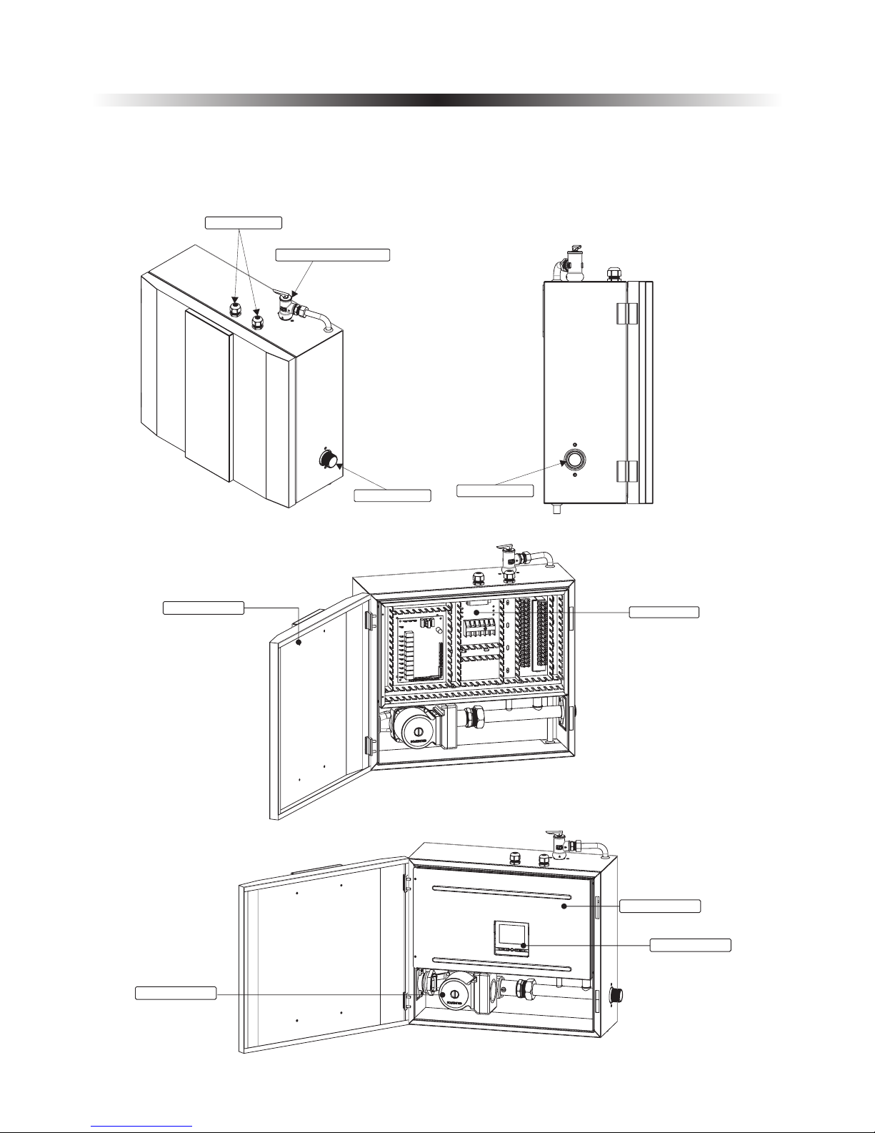
Operation panel
Cable gland
Water outlet
Water inlet
1.3 Main components
1. Before use
1.3.1 Indoor control unit
7
Press ur e Re li ef Valves
Electric box
Door
Electric box cover
Water pump
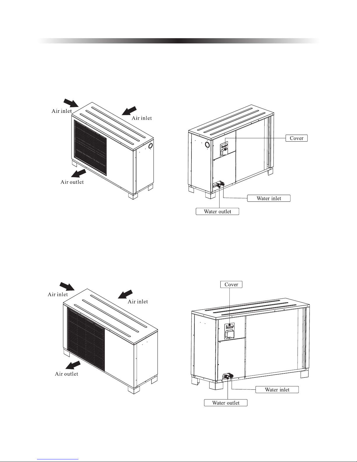
1.3.2 Monoblock unit
1. Before use
8
AW9-V5+
AW11-V5+
1. Before use
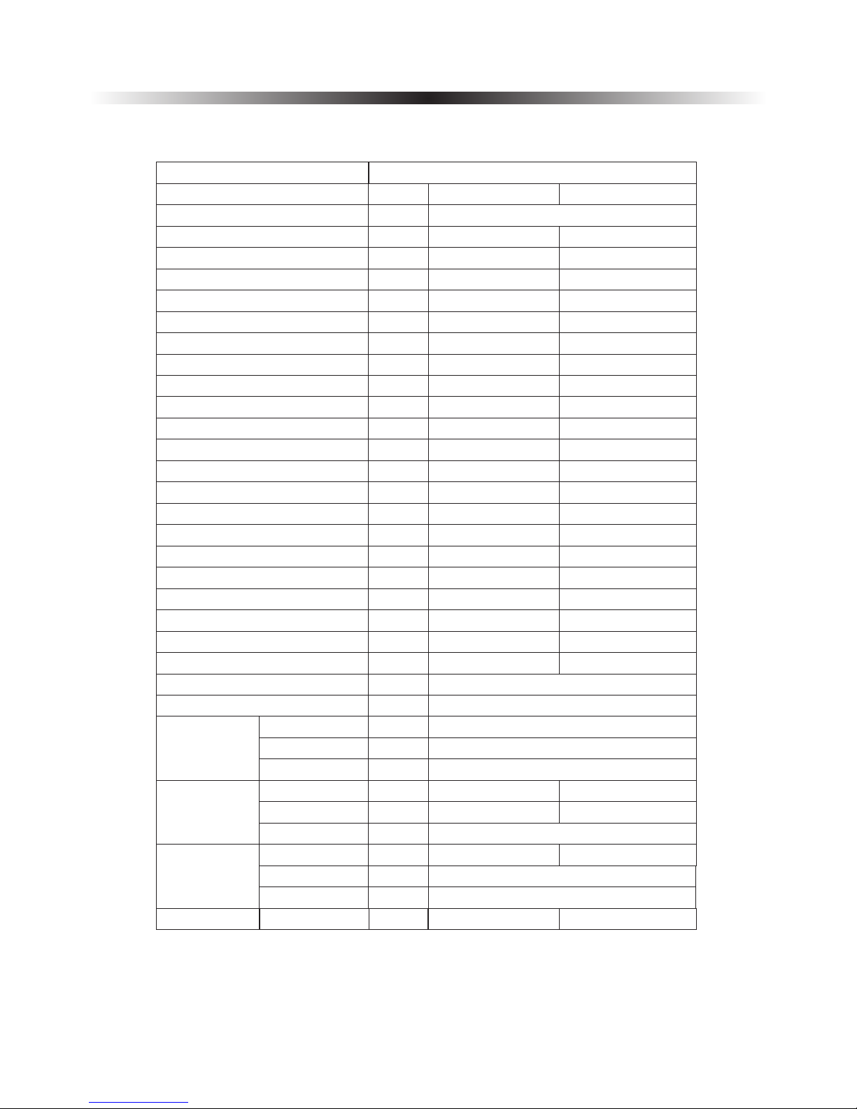
1.4 Specifications
9
Model
Power Supply
V/Hz/Ph
AWH11-V5+
AWH9-V5+
220-240/50/1
Refrigerant
Max. Heating Capacity (1)
C.O.P (1)
Heating Capacity Min./Max.(1)
Heating Power Input Min./Max.(1)
C.O.P Min./Max.(1)
Max. Heating Capacity(2)
C.O.P (2)
Heating Capacity Min./Max.(2)
Heating power input Min./Max.(2)
C.O.P Min./Max.(2)
Max. Cooling Capacity(3)
E.E.R (3)
Cooling Capacity Min./Max.(3)
Cooling Power Input Min./Max.(3)
E.E.R Min./Max.(3)
Max. Cooling Capacity(4)
E.E.R(4)
Cooling Capacity Min./Max.(4)
Cooling Power Input Min./Max.(4)
E.E.R Min./Max.(4)
KW
W/W
KW
W
W/W
KW
W/W
KW
W
W/W
KW
W/W
KW
W
W/W
KW
W/W
KW
W
W/W
11.510.10
3.824.03
4.67/11.5
4.33/10.10
915/3029
975/2153
3.82/5.05
4.02/4.65
10.7
9.53
2.95
3.17
4.14/10.74.19/9.53
1218/36241230/2990
2.95/3.563.12/3.55
9.2
6.84
2.682.09
4.33/9.24.10/6.84
993/3465
1230/3280
2.685/4.11
2.09/3.32
6.745.05
2.15
1.58
2.17/6.742.34/5.05
924/31321080/3200
2.15/3.01.58/2.40
R410A/1.9
R410A/2.45
Circuit Max. Pressure
bar
42
Rated Power Water Pump
W
Compressor
Type
Quantity/System
Twin Rotary
1
Oil
Fan
Quantity
Airflow
Rated Power
m³/h
W
31003000
60
1
1
Allowable
Fan Flow
Face Area
Row-Fins/Inch
Tube.Dia
m²
Inch
0.8710.542
Kg
Type of Product
DC Inverter Air to Water Heat Pump Unit
Noise Level
Indoor/Outdoor
30/56
dB(A)
87
FV50S
3/8 O.D
2 Rows-14
30/56
1. Before use
10
NOTE:
(1) Heating condition: water in/out temperature:30℃/35℃, ambient temperature:DB/WB 7/6℃;
(2) Heating condition: water in/out temperature:40℃/45℃, ambient temperature:DB/WB 7/6℃;
(3) Cooling condition: water in/out temperature:23℃/18℃, ambient temperature:35℃;
(4) Cooling condition: water in/out temperature:12℃/7℃, ambient temperature:35℃.
(5) The specifications are subject to change without prior notice.
For actual specifications of the unit, please refer to the specification stickers on the unit.
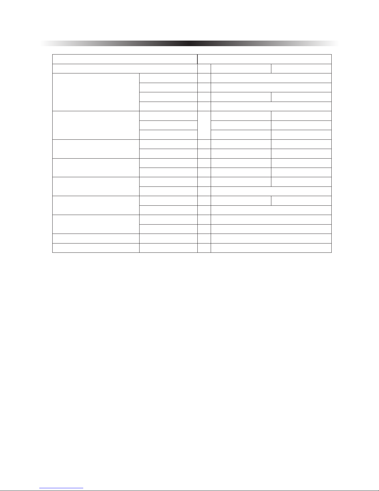
Net Dimension (L×D×H)
Packing Dimension (L×D×H)
Net Weight
Packing Weight
Outdoor Unit
Indoor Unit
Outdoor Unit
Indoor Unit
Outdoor Unit
Indoor Unit
Outdoor Unit
Indoor Unit
1215×415×7601064×353×754
500 495 210× ×
1310× ×830520
1130 460 904× ×
94
20
81
98
86
Water Side Heat Exchanger
Allowable Water Flow
Type
Water Pressure Drop
Piping Connection
Min. Water Flow
Rated Water Flow
Max. Water Flow
23
G1”
0.520.43
0.310.26
0.620.51
Material
Heating
Cooling
Operating Ambient Temp. range
Operating Inlet Water Temp. range
Water Volume
mm
mm
mm
mm
Kg
Kg
Kg
Kg
Kpa
Inch
L/S
℃
℃
℃
Kg
18
-25~46
0~55
7~75
4.5
Plate Heat Exchanger
Stainless Steel+Copper
Model
Type of Product
DC Inverter Air to Water Heat Pump Unit
23
600×520×260
AWH9-V5+ AWH11-V5+
500 495 210× ×
600×520×260
2. Installation
11
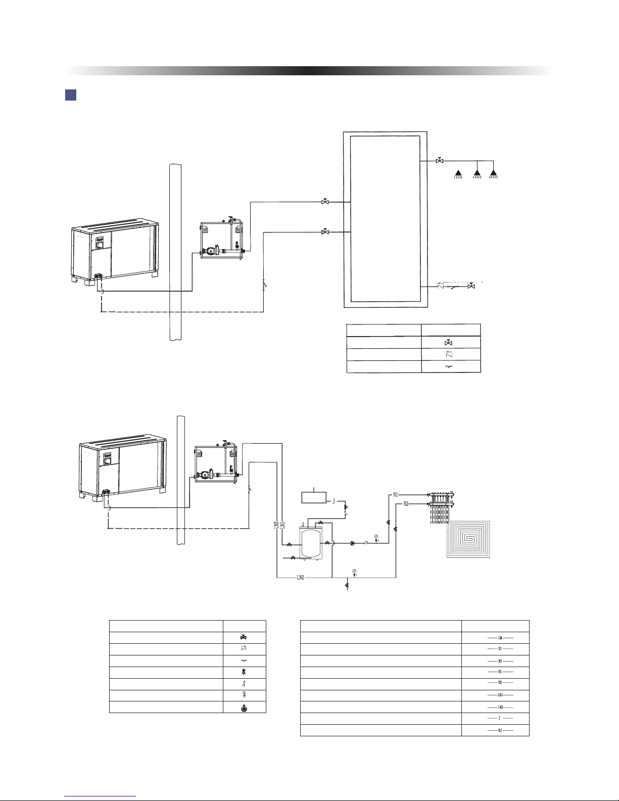
2.1 Application system introduction
To city water
Wate r disch arge outlet
De 25
De 3 2
De 3 2
De 40
De 4 0
De 2 5
De 2 5
De 3 2
De 3 2
UP S 2 5 / 8 0
热水 出 水
口G1
"
生活热
水补 水
口
G1
"
G1
"
G1
"
AH
-
2
00
L
40
~
5
0℃
Application 1: Sanitary hot water
Hot wa ter outle t
City water inlet
Application 2: Floor heating system
Name
Drawing
Ball valve
One way valve
Filter
Drain outlet
30L buff er t ank
Floor heatin g
distributi on sy ste m
Name
Drawing
Ball valve
One way valve
Filter
Safe valve
Air discharge valve
Water pressure gauge
Motor three way valve
Refrigerant pipe
Hot water outlet pipe
Hot water inlet
Heating water outlet pipe
Heating water inlet pipe
Cooling/heating water outlet pipe
Cooling/heating water inlet pipe
City water inlet pipe
Sanitary hot water outlet pipe
Name
Drawing
2. Installation
12
De 3 2
De 3 2
De 4 0
De 4 0
De 2 5
De 2 5
De 3 2
De 3 2
UP S 2 5 / 8 0
12
11
9
10
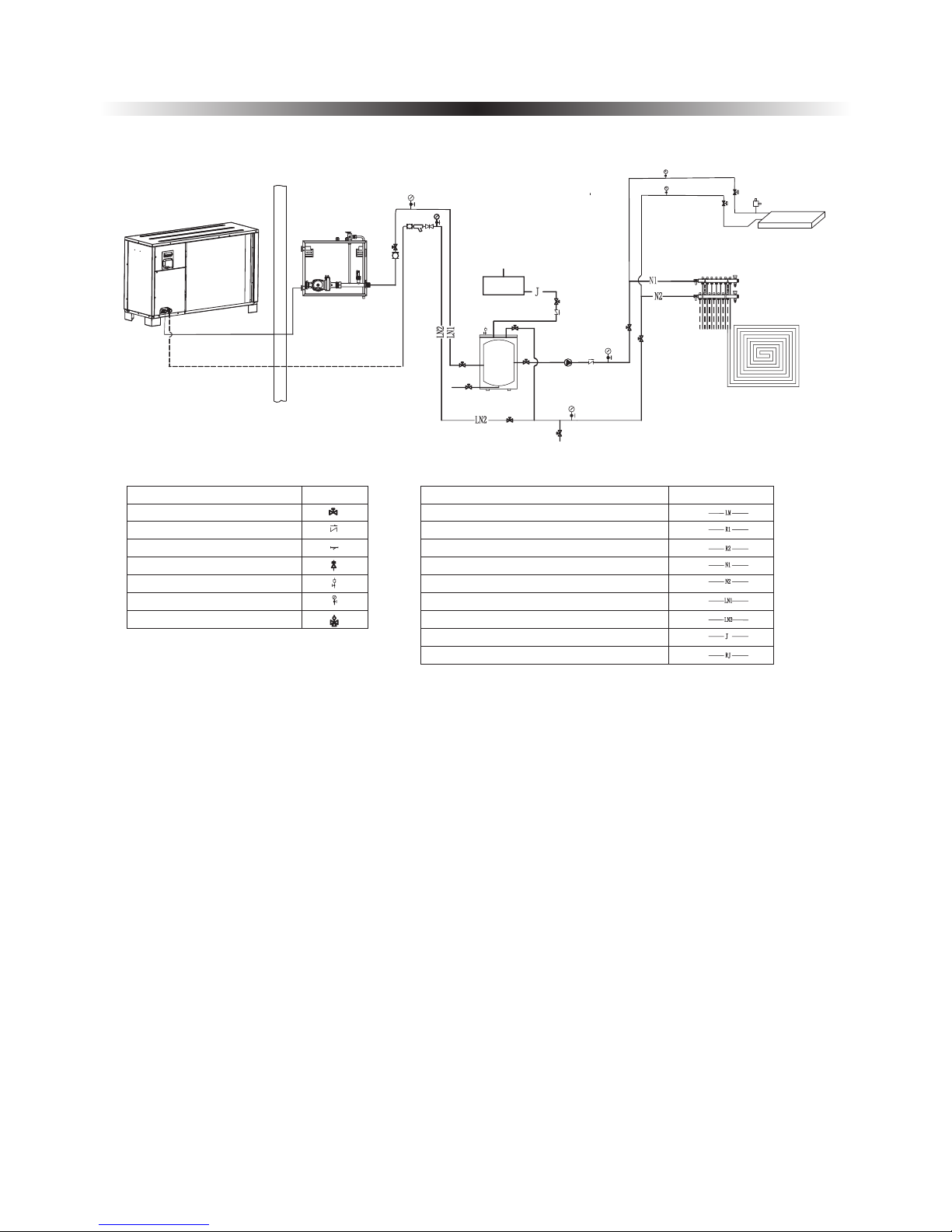
Application 3: Heating and cooling system
Fan coil unit
Floor heatin g
distributi on sy ste m
To city water
Drain outlet
30L buff er t ank
Wate r disch arge outlet
De 25
Name
Drawing
Ball valve
One way valve
Filter
Safe valve
Air discharge valve
Water pressure gauge
Motor three way valve
Refrigerant pipe
Hot water outlet pipe
Hot water inlet
Heating water outlet pipe
Heating water inlet pipe
Cooling/heating water outlet pipe
Cooling/heating water inlet pipe
City water inlet pipe
Sanitary hot water outlet pipe
Name
Drawing
The installation of the product should be handled by professional installers or under their
instructions.
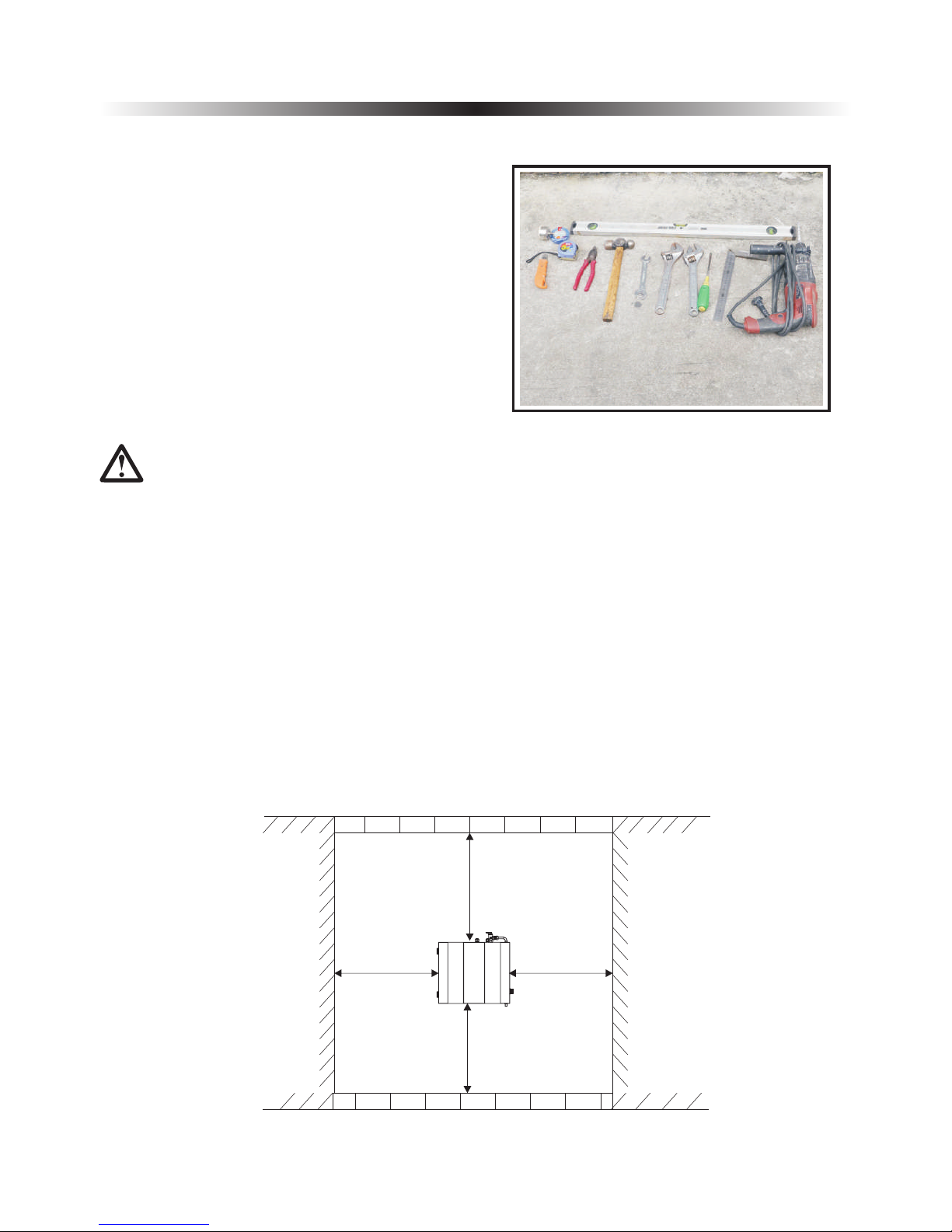
>500mm
>100mm >100mm
>500mm
2. Installation
2.2 Tools needed
2.3 Installation of the indoor control unit
Most people already have the tools needed for
installation: spirit level, pencil, crosshead
screwdriver, drill, 8 mm. concrete drill bit, detection
drill, square, tape measure or ruler, tape width 65
mm, hole saw about 80 mm (deviation in size may
occur), knife and two adjustable spanners or pliers
(and possibly torque wrench).
2.3.1 Installation notes
1)
2) The indoor unit shall be placed in dry and well-ventilated environment.
3) Indoor unit mustn't be installed in an environment where volatile, corrosive or flammable liquid
or gas exists.
4)
The indoor control unit should be installed indoors and mounted on the wall, with water outlet
downwards.
control
control
control
Please choose a suitable position to install the indoor control unit as follows:
Enough space should be left around the indoor unit for futher maintenance.
13
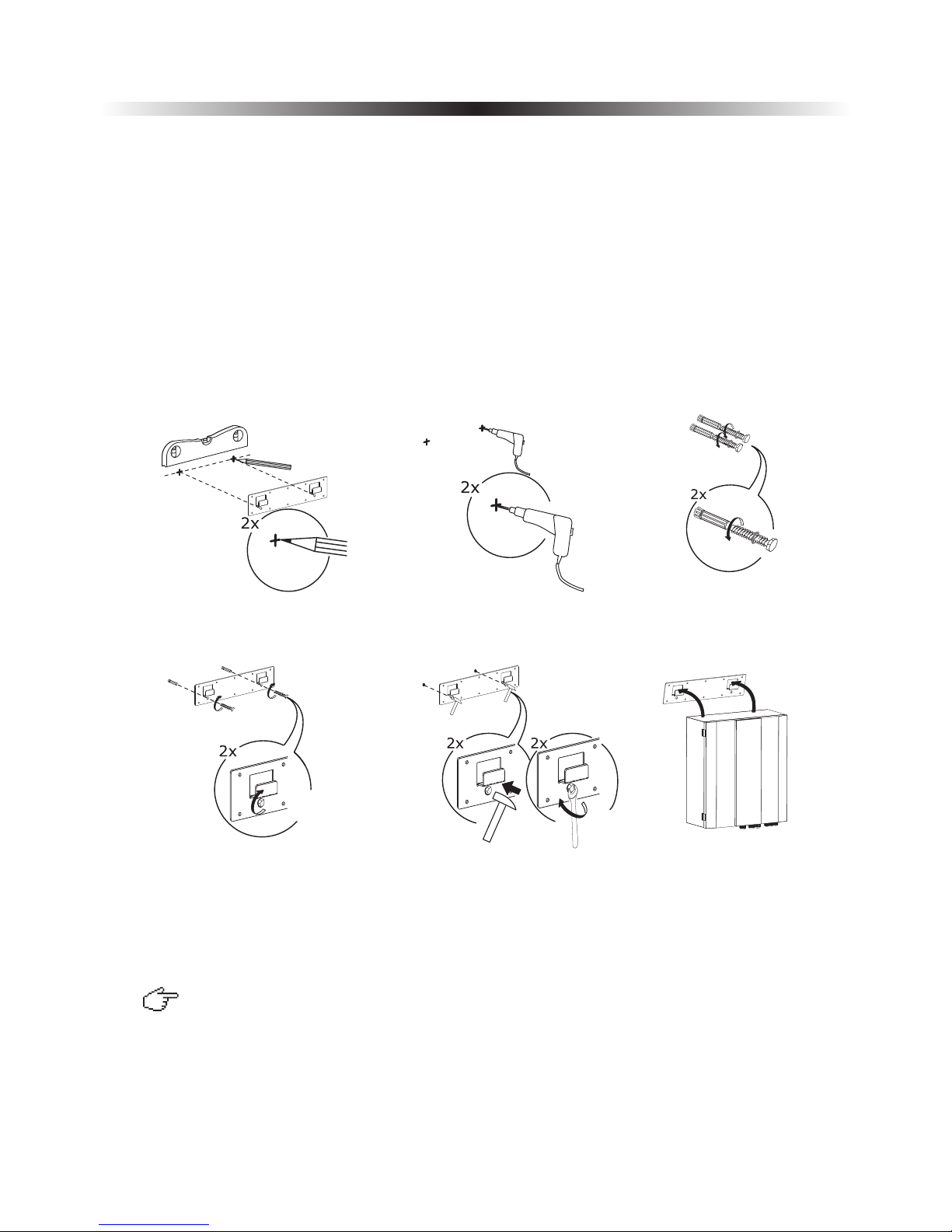
2.3.2 Installation
Indoor unit should be mounted on the wall as per procedures below:
1) Take out the expansion bolts and mounting board from accessory and put the mounting board on the
wall horizontally; Mark on the wall the location for bolts through the holes on mounting board.
2) Drill holes with proper diameter for expansion bolts.
3)
4)
5)
6) Hang the indoor unit onto the mounting board and make sure it's placed well before you let go
your hands. The installation is finished.
control
Unscrew the nuts out from the expansion bolts.
Fix the mounting board on the expansion bolts a little bit, but don't be too tight.
Use a hammer to pound the expansion bolts into the drilled holes. Fasten the nuts by turning the wrench
to fix the mounting board on the wall.
control
2. Installation
1
2 3
4
5 6
Note:
You must choose very firm wall for installation otherwise the bolts may get loose and unit be damaged!
If it's wood wall, please use self-tapping screws in accessory instead of bolts. Please hang
the mounting board directly onto the wood wall without drilling holes. The wood wall must be firm
enough. Wood walls that are too thin, too brittle or humid are not adequate for installation.
expansion
14
2.4 Installation of the monoblock unit
2.4.1 Installation notes
1) The monoblock unit can be located in a open space, corridor, balcony, and roof.
2) The unit shall be placed in dry and well-ventilated environment;
3) unit mustn't be installed in an environment where volatile, corrosive or flammable liquid or
gas exists.
4) Please don't install unit close to bedroom or living room, because there is some noise when
it's running.
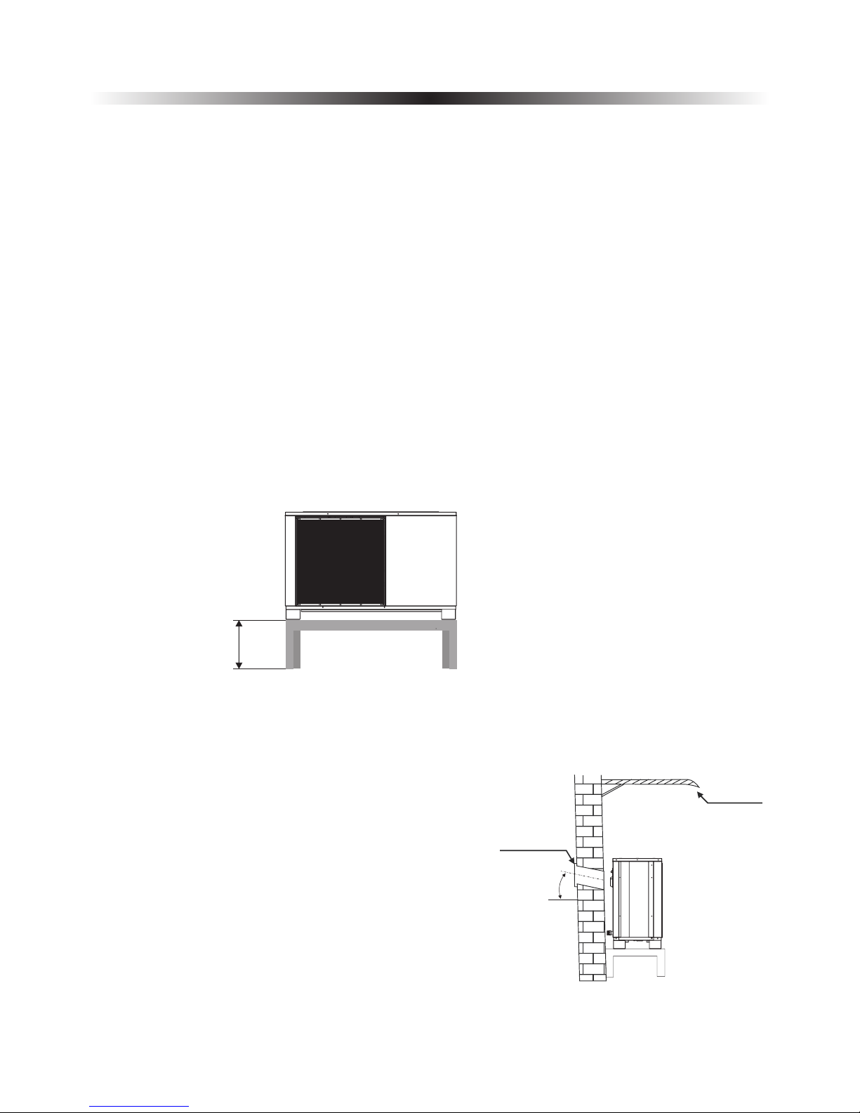
5) When installing the unit in harsh climatic conditions, sub-zero temperatures, snow, humidity..., please
raise the unit above the ground by about 50cm.
6) Please ensure there is drainage system around the location, to drain the condensate water under
defrosting mode.
7) When installing the unit, tilt it by lcm/m for rain water evacuation.
8)
9) Please don't install the indoor control unit and unit in damp locations, otherwise it may
cause short-circuit or corrosion of some components. The unit should be free from corrosive and
moisture surrounding. Otherwise the lifetime of the unit might be shortened.
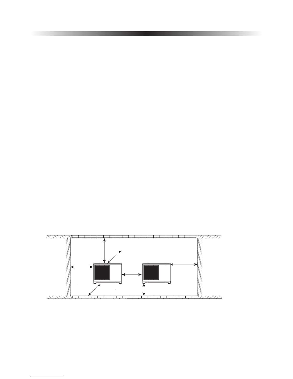
10) Please ensure enough space around the unit, for better ventilation and maintenance.
Please refer to the illustration below.
monoblock monoblock
Monoblock
monoblock
monoblock
monoblock
monoblock
monoblock
monoblock
If the unit is
installed in humid environment, electronic components may get corroded, or short-circuited because of
heavy humidity.
It's recommended to install an awning above the unit, to protect the snow from clogging in
the air inlet and outlet and ensure the normal running.
Install unit far away from the exhaust port of kitchen, to avoid oil smoke entering
into unit and adhering to heat exchanger. It's hard to clean up.
2. Installation
15
≥650mm
≥400mm
≥150mm( )Back space
≥1500mm
()Front
space
≥500mm
≥500mm
≥500mm
( )Above ground
2. Installation
2.4.2 Installation
User can either use the dedicated mounting bracket from the supplier, or prepare a suitable bracket for the
unit installation. Make sure the installation meets following requirements:
1) The unit must be installed on flat concrete blocks, or a dedicated mounting bracket. The bracket should
be able to support at least 5 times of unit’s weight.
2) All nuts must be tightened after the bracket is fixed; otherwise, it may cause damage to the equipment.
3) User should double check and make sure the installation of unit is firm enough.
4) The bracket can be of stainless steel, galvanized steel, aluminum and other materials as required by the
user.
5) Besides the mounting bracket, the user can also install the monoblock unit on two concrete blocks, or a
raised concrete platform. Please make sure that the unit is securely fastened after installation.
6) Please see the dimensions of unit when choose a suitable wall bracket. monoblock
≥500mm
◆ Hole for piping kits should lean to outside a little bit
(≥8 degrees), to keep rain water or condensate water
from flowing back indoors.
≥8°
Sleeve
Shield
16
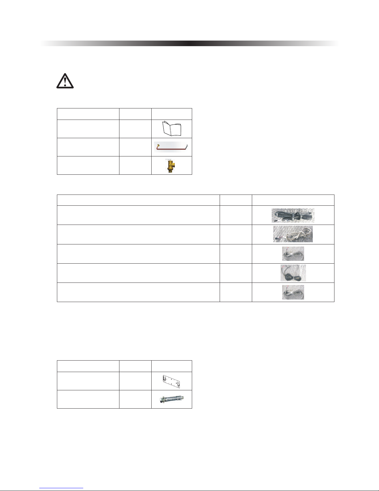
2.5 Accessories
Accessories below are delivered together with the product .
Please check in time. If there is any shortage or damage, please contact local distributor.
Name
Quantity
Picture
User’s manual
Drain pipe
1
Safety valve kit
1
1
User Ma nual
2. Installation
Indoor control unit
bracket
1
Expansion bolts
2
Name
Quantity
Picture
17
Name
Quantity
Picture
1
1
TR-Room temperature sensor
TC-water temperature sensor for cooling
TH-water temperature sensor for heating
1
Communication cable between indoor control unit and
monoblock unit
Communication cable
Signal cable between indoor control unit and monoblock
unit
1
1
TW-Water temperature sensor for hot water
◆
◆
◆
◆
◆
◆
◆
◆
◆
It is recommended to use a suitable circuit breaker for the heat pump;
The power supply to the heat pump unit must be grounded.
The wiring should be done by professional person.
The wiring should be comply with the local industry regulation.
The wiring should be done after the unit is powered off.
Cable should be fixed tightly, to ensure it won’t get loose.
Don't connect several parts of cables together to use.
Make sure the power supply in the local coincide with the power supply marked in rating label.
Make sure power supply, cable and socket can meet the requirement of the input power of the unit.
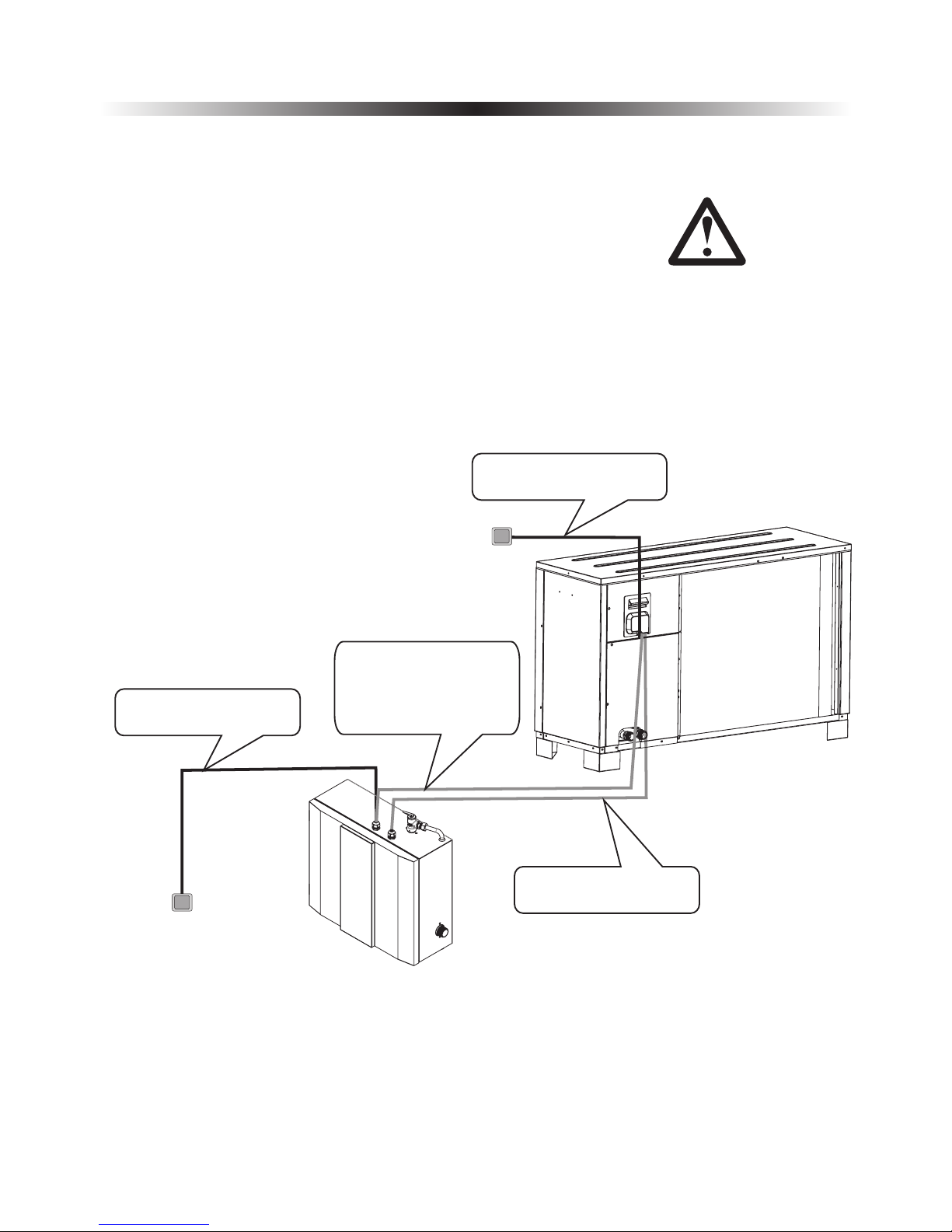
2.6 Wiring
2. Installation
Installation sketch
18
Signal cable between
indoor and outdoor unit
Main power
in user side
Heat pump unit power
supply
Aluminum foil electric
heating piece power cable
between indoor control
unit and monoblock unit
Heat pump monoblock unit
power supply
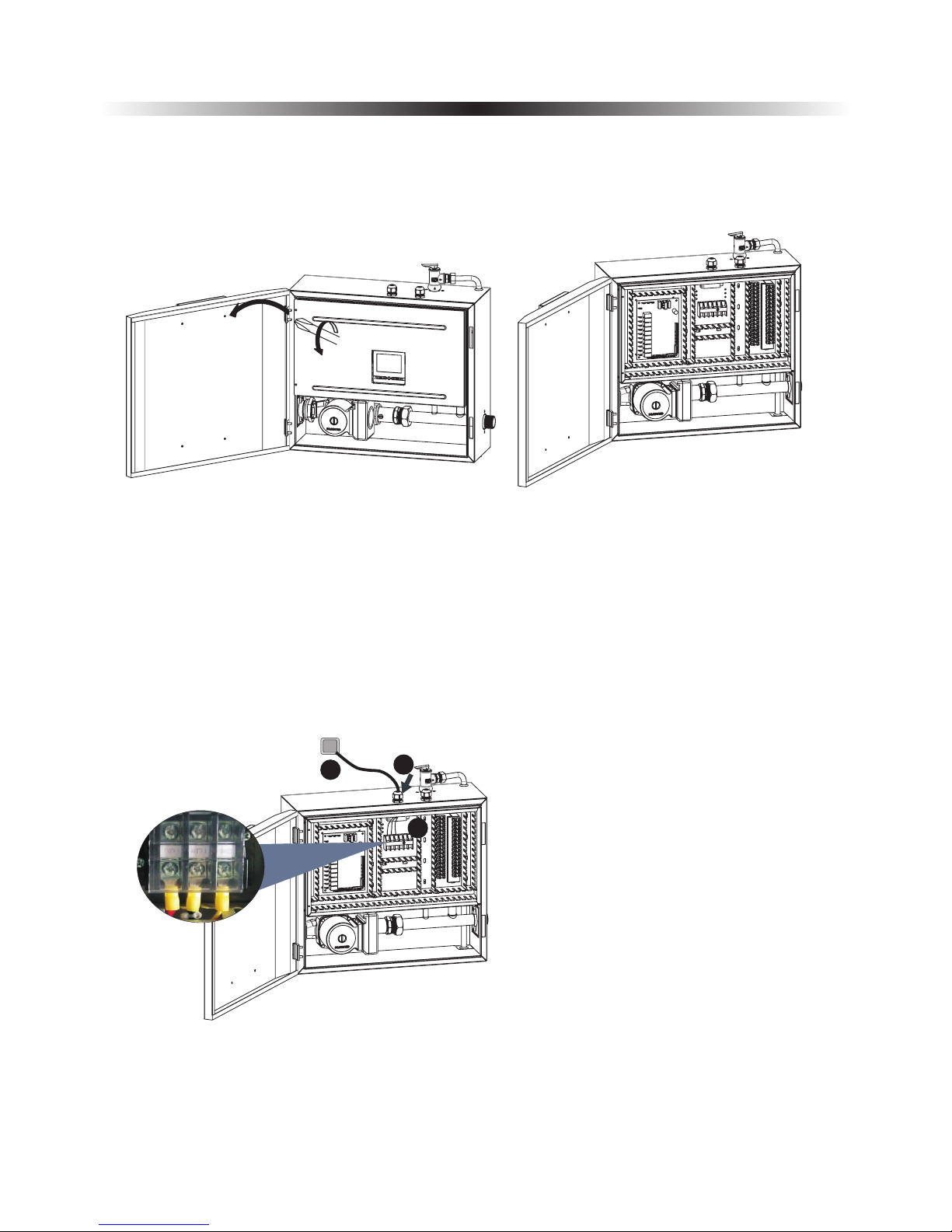
1) Heat pump unit power supply
Get a power cable in suitable length that complies to the local safety regulations.
Before wiring, open the indoor control unit front panel and take off the electronic box cover.
A. Insert one end of this cable through the
cable gland on bottom of the indoor control
unit, and connect it with heat pump power
supply terminals (G, N, L).
B. Fasten the cable gland to ensure the cable
won't get loosen.
C. Connect the other end to the city power
supply.
2. Installation
19
A
B
C
G N
L
2. Installation
20
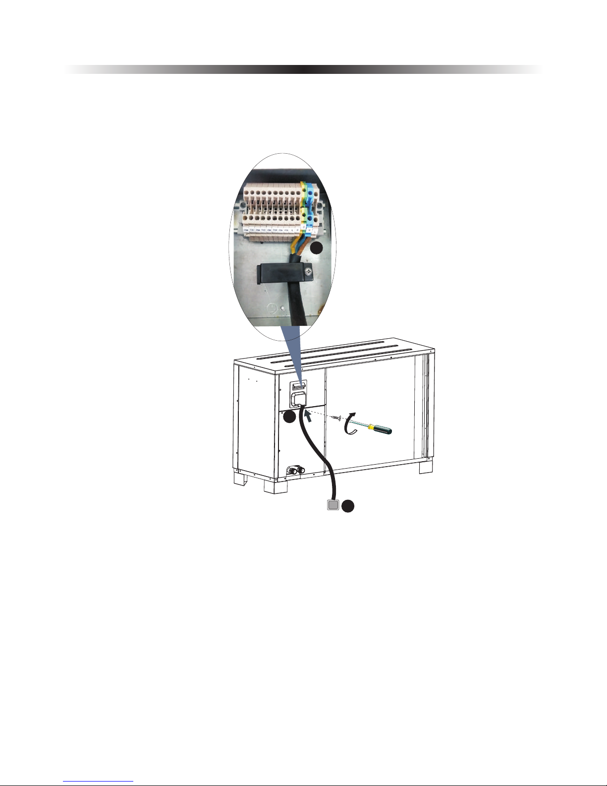
2) Monoblock unit power supply.
C
B
A
Get a power cable in suitable length that complies to the local safety regulations.
A. Insert one end of this cable through the cable gland on back of the outdoor control unit,
and connect it with heat pump power supply terminals (G, N, L).
B. Fasten the cable gland to ensure the cable won't get loosen.
C. Connect the other end to the city power supply.
2. Installation
21
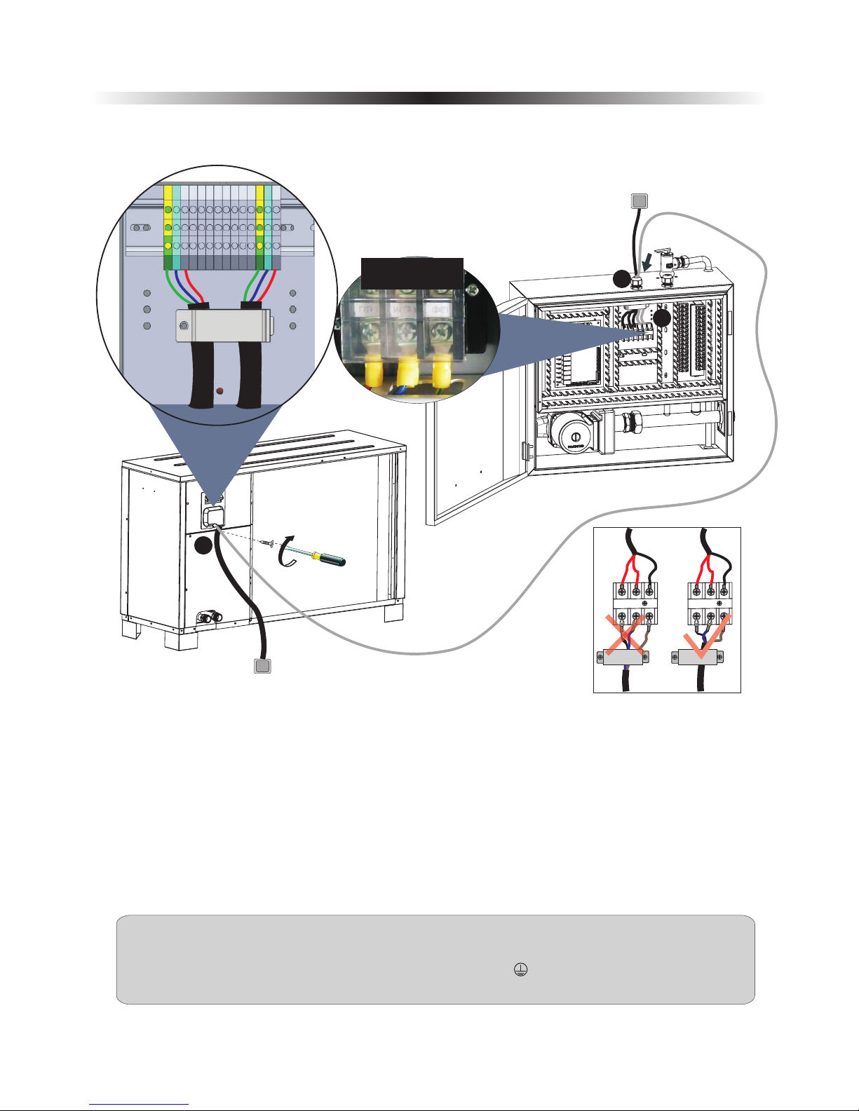
When connecting the power cable between the monoblock unit and indoor control unit, cables
connected to the terminal block in indoor control unit must match these in monoblock unit.
For example, if the terminals and power cables are connected as →gree/yellow cable, L→red cable,
N→blue cable, the connections in the monoblock unit should be in the same way.
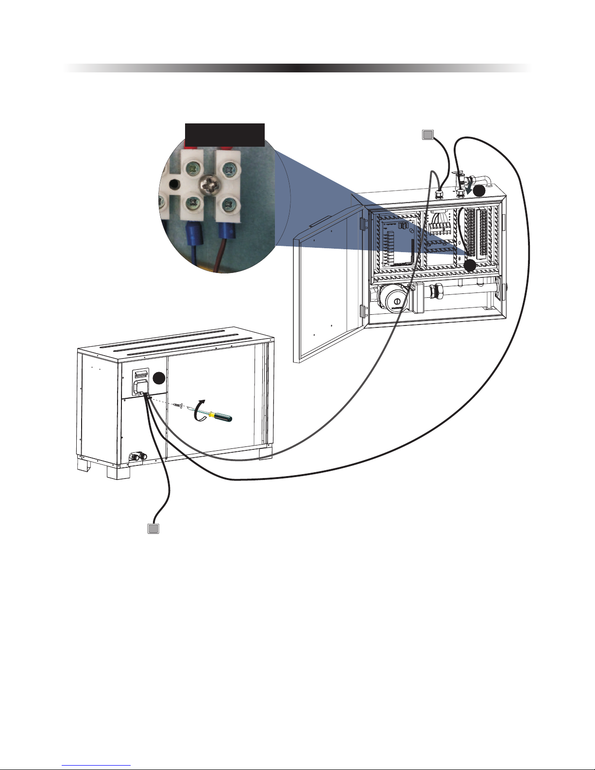
3) Aluminum foil electric heating piece power cable between indoor control unit and monoblock unit
Prepare a 3 cores power cable with suitable length that complies the local safety regulations,
A. Insert one end of this cable through the cable gland on top of the indoor control unit, and connect
this power cable to "Outdoor unit” on indoor control unit terminal block.
B. Fasten the cable gland to ensure the cable won't get loosen.
Connect cable between indoor control unit and monoblock unit to correspondent terminal block
according to the wiring diagram. Fasten the cable gland to ensure the cable won't get loosen.
C.
C
B
Sho wn as "Ou tdoor u nit
" on wi ring di agram
G
HN
HL
For more solid connection, for that cables that need to be connected with terminals:.
1.Please try to use solid ware instead of strand wire.
2.If stranded wire is used, please make a pin terminal on the end.
3.The stripped length of the wire should be no shorter than 10mm.
A
Warning.
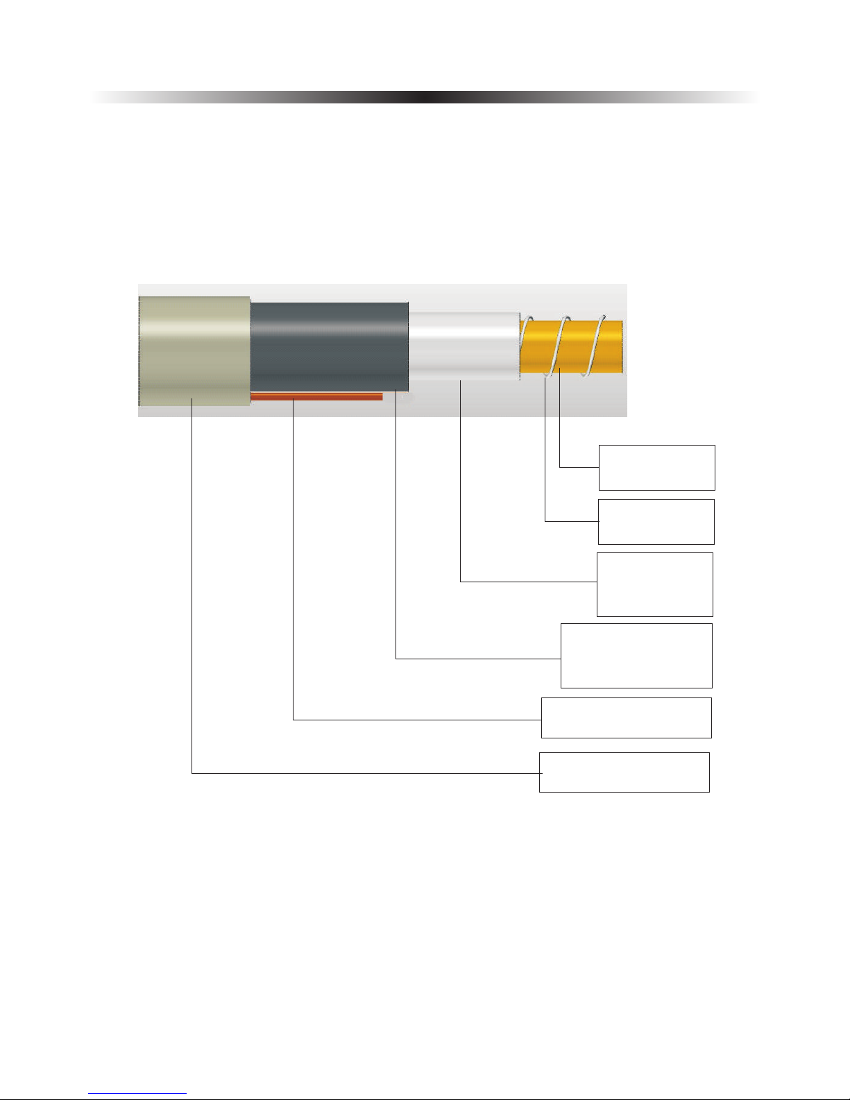
Electric heater for water lines inside outdoor cabinet must be attached. Pipe insulation must be able
to hold 120℃. Separate power supply to heater.
Water pipe connected between monoblock unit and house (water pipe in between should not longer
than 50cm.)
2. Installation
22
Copper or Steel
water pipe,28mm
Electric heating
cable.
Aluminum foil,
reflex heat back
to water pipe.
Insulation, that
can hold temperature
over 120℃
Power and signal cables
Wrapping material.
2. Installation
23
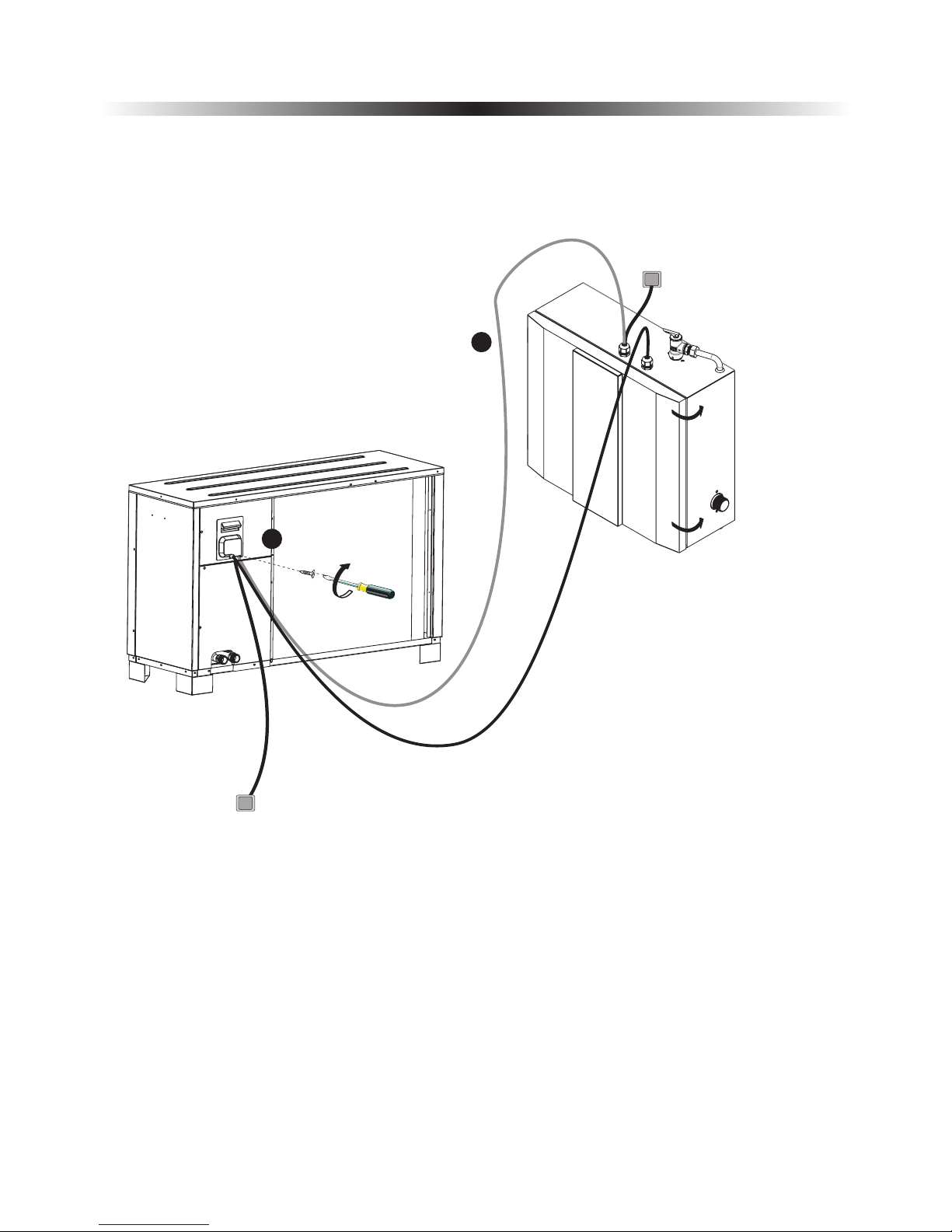
4) Signal cable between indoor control unit and monoblock unit
10M communication cable is packed in accessories bag.
A. Insert one end of this cable through the cable gland on top of the indoor control unit, and connect
this cable to A, B, on terminal block.
B. Fasten the cable gland to ensure the cable won't get loosen.
Take off the electric box cover, and connect the other end of communication cable to correspondent
terminal block through cable gland. Fix the cable with cable gland after cable is well connected. A, B,
on monoblock unit should be connected with A, B on indoor control unit, otherwise unit will show
communication failure.
C.
C
B
A
B
corresponding
with each other
A
2. Installation
24
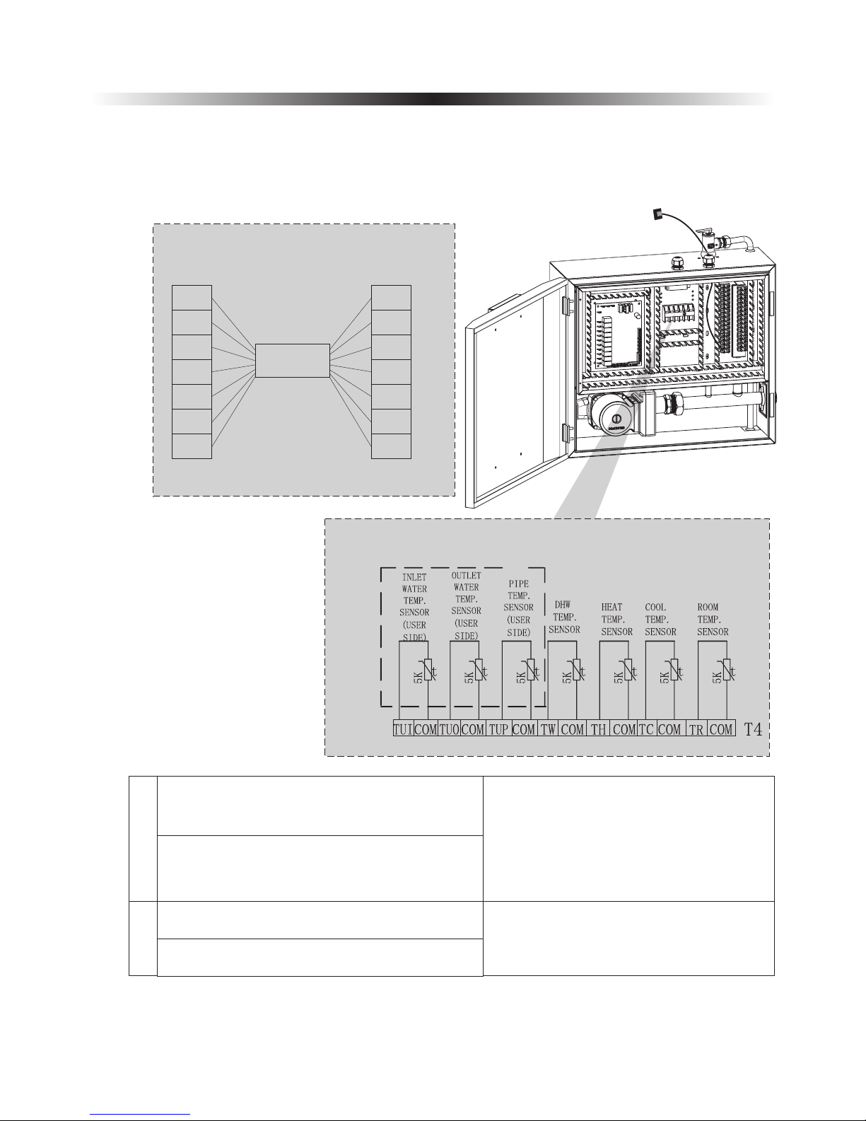
5) Sensor cables
Take all sensors and communication cables out from the accessories bag. Connect the sensors together with
the quick connectors on communication cables. After done, insert communication cables (the end without
quick connector) that have no quick connector through cable gland, and connect them to the correspondent
terminals on terminal block.
A
TR-Room temperature sensor
B
TUP-Coil temperature sensor
TUI-Water inlet temperature sensor
Connect these sensors with communication
cables by quick connector, and then connect
communication cable (the end without quick
connector) with terminal block. (These
sensors are packed inside the accessories
bag).
TUP/TUI/TUO(terminal of indoor PCB
and outdoor sensor) are connected to the
terminal board, connect via cushion cable.
Place all sensors in right positions
Sensor cable connection
Indoor control
Communication cable
CO M
TU I
CO M
TU O
CO M
TU P
CO M
CO M
TU I
CO M
TU O
CO M
TU P
CO M
TC-water temperature sensor for cooling
TH-water temperature sensor for heating
TW-Water temperature sensor for hot water
2. Installation
Install the electric box cover on indoor control unit and electric box cover on monoblock unit
back, and close the door of indoor control unit.
25
C
C
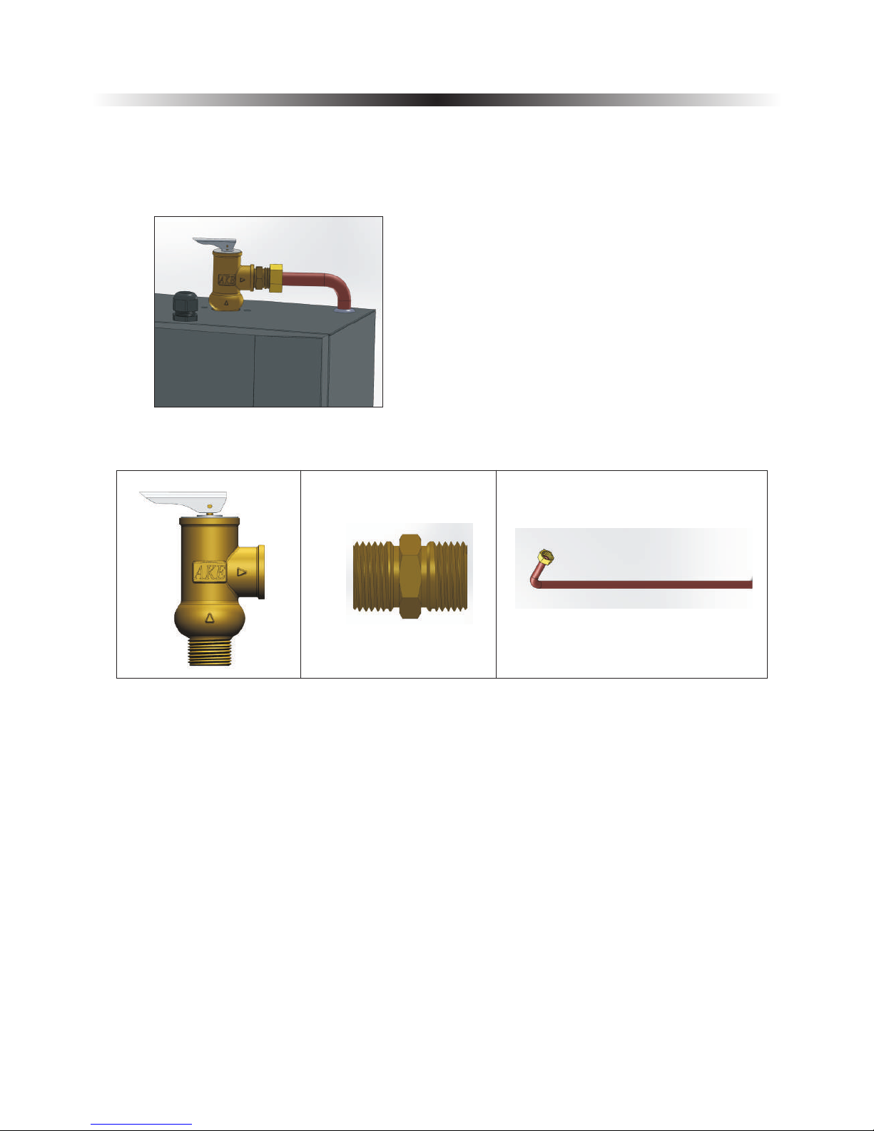
2.7 Installation of safety valve kit
1) Install the safety valve kit to the connector on top of indoor control unit.
2) Connect the drainage pipe to safety valve outlet.
2. Installation
26
 Loading...