

ES AWH6-V6-SW, AWH13-V6-SW, AWH9-V6-SW, AWH11-V6-SW User Manual
Heat Pump
DC Inverter Air to Water
Before operating this product, please read the
instructions carefully and keep this manual for future use.
User’s manual
User’s manual
AWH6-V6-SW
AWH9-V6-SW
AWH11-V6-SW
AWH13-V6-SW

2

5
Catalogue
1.Introduction
1.1.Preliminary Information
1.2.Safety Precautions
1.3.Functioning Principles
1.4.Product Component Diagram
1.5.Technical Specifications
2.Overview of the Units
2.1.Functional Diagrams
2.2.Outlines and Dimensions
2.3.Exploded Views
3.Assembly Configurations
Assembly Configuration Selection Flowchart
Assembly Drawings, Wiring, and Software
4.Installation Walkthrough
4.1.Sanitary Hot Water Applications
4.2.Heating and Cooling Circuits
4.3.Indoor Unit Installation
4.4.Outdoor Unit Installation
4.5.Wiring
4.6.Refrigerant Pipework
4.7.Water Pipework
4.8.Test Run
5.Appendix
A. Wiring
5
3
6
8
9
10
11
11
13
15
19
19
20
49
49
53
56
58
60
70
73
74
75
75
B. Wiring Diagrams
77
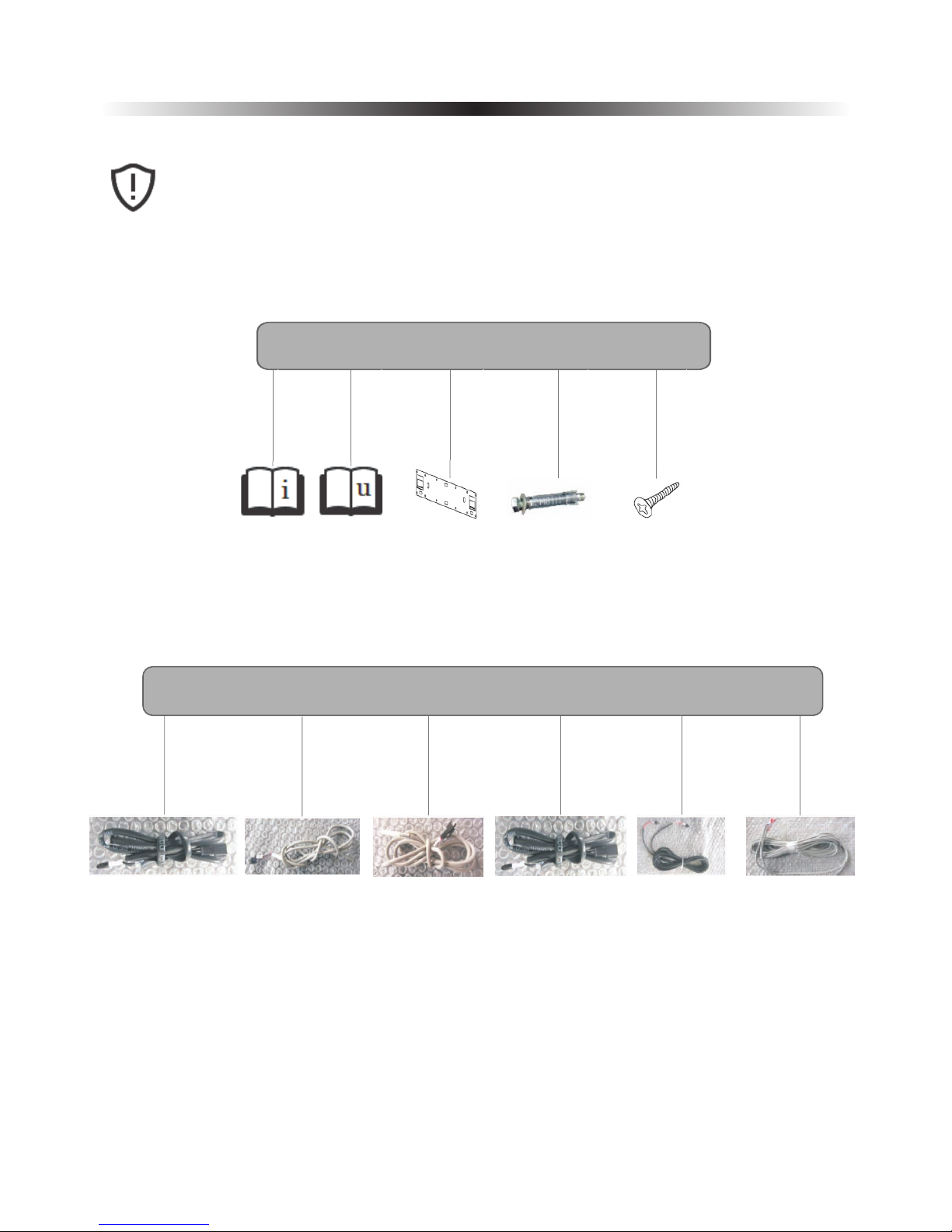
Installation
Manual
User’s
Manual
Indoor
Unit
Bracket
Expansion
Bolts
Below are the accessories that are included with your purchase.
Please check to ensure that none are missing or damaged.
If so,please contact your local distributor.
Included Accessories
Screws
1 2
3
4
5
X1 X1 X1 X2
X10
4
Temperature
TC-Water
Sensor
Temperature
Sensor
(for cooling
and heating)
TR-Room
Temperature
Sensor
(for sanitary
hot water)
TV(1+2)- Water
Temperature
Sensors for
Mixture Valves
Sensor
Communication
Cable
Communication
Cable between
Indoor and
Outdoor Unit
TR - Room
(1+2)
6
7
8
9 10
11
X1 X1 X1 X2 X4 X1

1. Introduction
1.1 Preliminary Information
Thank you for your purchase of our quality heat pump.
This manual is intended to provide detaile d instructions for the successful installation o f your newly
purchased heat pump product. Please ensure that this manual, along w ith the User ’s and Service
manuals, are kept in an easy-to-access location for your reference later on.
DISCLAIMER
Proper adherence to the directions provided herein is vital for both t he smooth operation of this
system, as well as for your safety and the safety of those around you. Amitime Electric Co., Ltd. is not
responsible or liable for any losses incurred due to misuse or mishandling of this product, which
includes, but is not limited to:
• Purchasing, installing, and/or operating this product with the intention of using it outside of
its established, technical purpose.
• Carrying out improper work upon the unit, or any of its components, that has not been given
explicit, prior consent in the form of writing.
• Installation attempts of this system by anyone other than a properly trained and licensed
professional.
• Negligence of properly-worn personal protection (safety glasses, gloves, etc.) while performing
installation, maintenance, or servic ing of this product.
SAFETY
• The operation of this system during ambient temperatures which are b elow or beyond the
temperature range intended (-25°C to 43°C)
If unsure of what installation procedures to use, please contact your local distributor for information
and/or advisement. Any accessories used with this pr oduct must be official only. Any electrical work
must be carried out by certified electricians only. The manufacturer is not responsible for any alterations or modifications that are made with out explicit, written approval. The design of thi s unit complies and conforms to all necessary and relevant safety regulation s, and is otherwise safe to op erate for
its intended use.
Please pay attention to the following pages, which detail importan t precautions that should be closely
followed, to ensure safe installation and operation .
5
1. Introduction
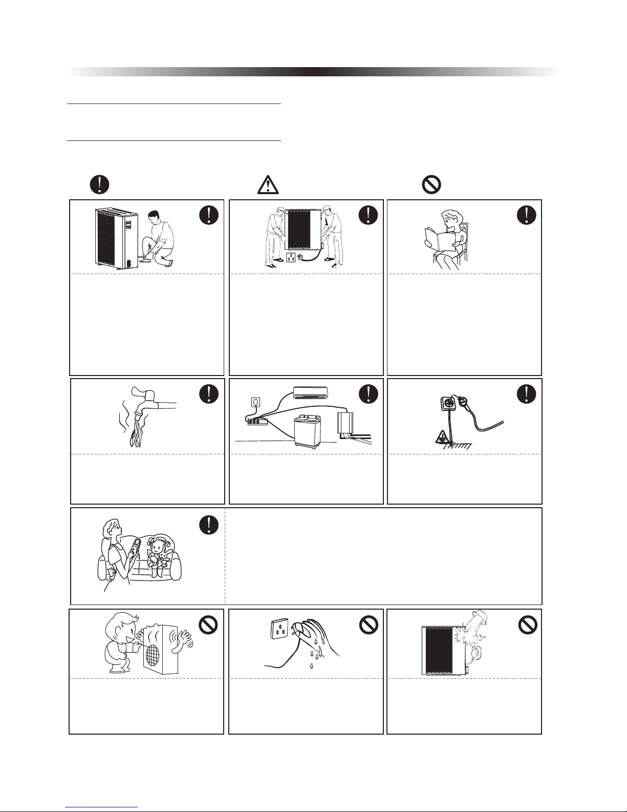
1.2.Safety Precautions
To ensure both your personal safety, as well as the safety of the product, note the symbols below and
be sure to understand their correlation to each of the precautions depicted.
CautionWarning
Prohibition
The installation, dismantlement
and maintenance of the unit must
be performed by qualified
personnel. It is forbidden to do any
changes to the structure of the unit.
Otherwise injury of person or unit
damage might happen.
To avoid electrical shock, make
sure to disconnect the power
supply 1 minute or more before
servicing the electrical parts. Even
after 1 minute, always measure the
voltage at the terminals of main
circuit capacitors or electrical parts
and, before touching, make sure
that those voltages are lower
than the safety voltage.
User Ma nual
Be sure to read this manual before
use.
For sanitary hot water, please
always add a mixture valve before
water tap and set it to proper
temperature.
Ground wire
Use a dedicated socket for this
unit, otherwise malfunction may
occur.
The power supply to the unit must
be grounded.
Do not touch the air outlet grill
when fan motor is running.
Do not touch the power plug with
wet hands. Never pull out the plug
by pulling the power cable.
Water or any kind of liquid is
strictly forbidden to be poured into
the product, or may cause electric
creepage or breakdown of the
product.
This appliance can be used by children aged from 8 years and above
and persons with reduced physical, sensory or mental capabilities or
lack of experience and knowledge if they have been given supervision
or instruction concerning use of the appliance in a safe way and
understand the hazards involved. Children shall not play with the
appliance. Cleaning and user maintenance shall not be made by
children without supervision.
6
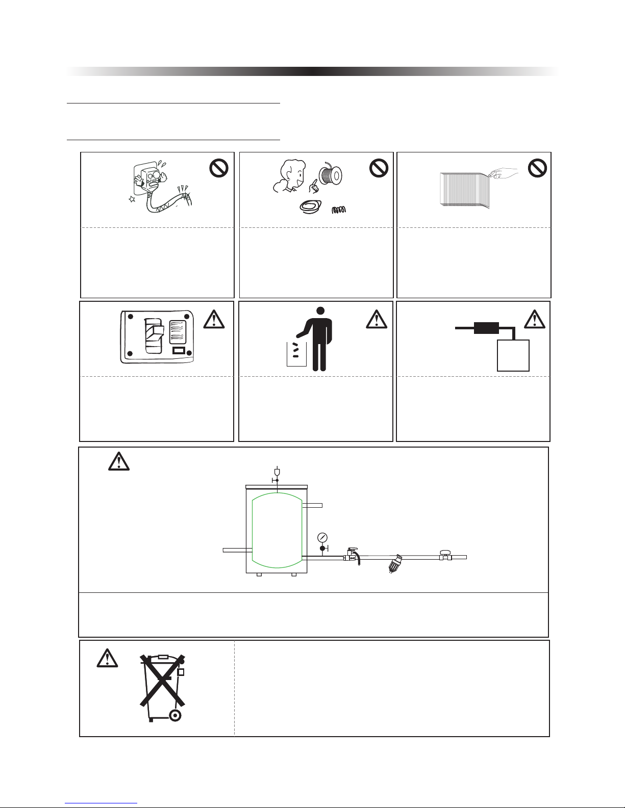
Copper
Steel
Fuse
Main
Power Cable
RCD
Indoor
unit
When the power cord gets loose
or damaged, always get a qualified
person to fix it.
It is mandatory to use a suitable
circuit breaker for the heat pump
and make sure the power supply to
the unit corresponds to the
specifications. Otherwise the unit
might be damaged.
Disposal of Scrap Batteries(if
there is).Please discard the
batteries as sorted municipal waste
at the accessible collection point.
Installation of a residual current
device (RCD) having a rated
residual operating current not
exceeding 30 mA is advisable.
ON
OFF
Please select the correct fuse or
breaker as per recommended. Steel
wire or copper wire cannot be
taken as substitute for fuse or
breaker. Otherwise, damages
maybe caused.
Be aware fingers might be hurt by
the fin of the coil.
7
This marking indicates that this product should not be disposed with
other household wastes throughout the EU. To prevent possible harm to
the environment or human health from uncontrolled waste disposal,
recycle it responsibly to promote the sustainable reuse of material
resources. To return your used device, please use the return and
collection systems or contact the retailer where the product was
purchased. They can take this product for environmental safe recycling.
System water filling
T/P valve
Connect to heating/cooling system
Buffer tank
Connect to heat pump
One way valve
Filter
City water inlet
1. It's suggested to use pure water for filling the system.
2. If use city water for filling, please soften the water and add a filter.
Note: After filling, the system of water system should be 0.15~0.6MPa.
1. Introduction
1.2.Safety Precautions
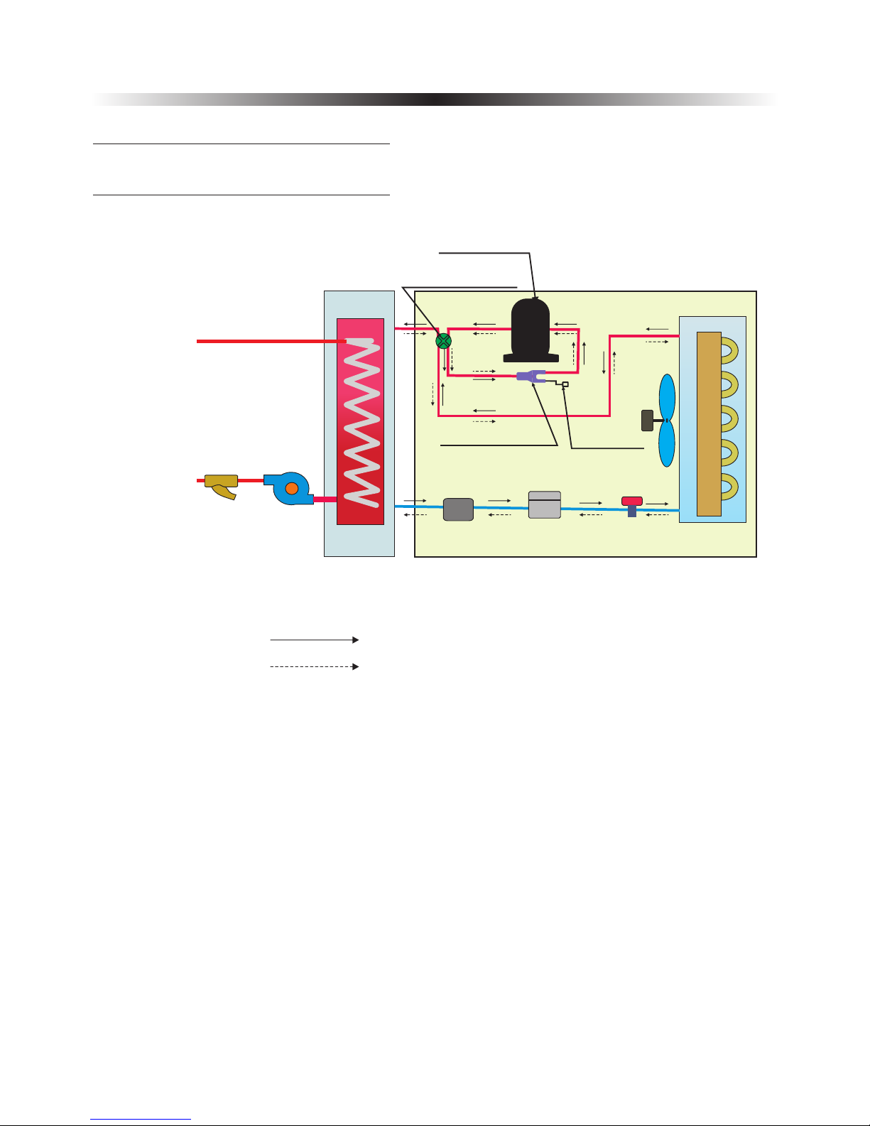
Water inlet
Water Outlet
Outdoor unitIndoor unit
Filter
Water pump
Heat
exchanger
Power supply
Four-way vavle
Compressor
Three-way valve
Refrigerant Filter
T-connector
Fan motor
Pressure
check valve
Evaporator
Heating
Cooling
8
1. Introduction
1.3.Functioning Principles
9
1. Introduction
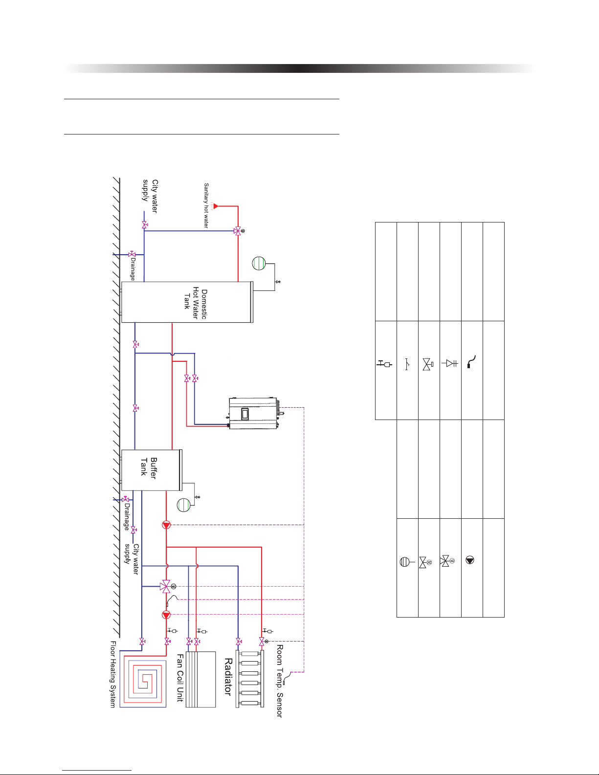
1.4.Product Components Diagram
Below is a general system application of the heat pump. Any specific configurations should be a
variation of this “master” system drawing. All suggested assembly variations are given in Chapter 3.
Name
Symbol
Name
Symbol
Temp.S en sor
Safe ty v alv e Ki t
Ball valv e
Wat er filt er
Air pu rg ing v al ve
Wat er pump
Mixi ng v alv e
Moto ri zed valv e
Expa ns ion t an k
Note:Dot te d li ne s me an〝a ble to be control le d by t he H ea t Pump〞.

10
Model
Power Supply-Refrigerant
V/Hz/Ph
AWH11-V6-SW
AWH9-V6-SW
220-240/50/1-R410A
Max. Heating Capacity (1)
C.O.P (1)
Heating Capacity Min./Max.(1)
Heating Power Input Min./Max.(1)
C.O.P Min./Max.(1)
Max. Heating Capacity(2)
C.O.P (2)
Heating Capacity Min./Max.(2)
Heating power input Min./Max.(2)
C.O.P Min./Max.(2)
Max. Cooling Capacity(3)
E.E.R (3)
Cooling Capacity Min./Max.(3)
Cooling Power Input Min./Max.(3)
E.E.R Min./Max.(3)
Max. Cooling Capacity(4)
E.E.R(4)
Cooling Capacity Min./Max.(4)
Cooling Power Input Min./Max.(4)
E.E.R Min./Max.(4)
KW
W/W
KW
W
W/W
KW
W/W
KW
W
W/W
KW
W/W
KW
W
W/W
KW
W/W
KW
W
W/W
11.5
10.10
3.82
4.03
4.67/11.5
4.33/10.10
915/3029
975/2153
3.82/5.054.02/4.65
10.7
9.53
2.95
3.17
4.14/10.74.19/9.53
1218/3624
1230/2990
2.95/3.56
3.12/3.55
9.2
6.84
2.68
2.09
4.33/9.2
4.10/6.84
993/3465
1230/3280
2.685/4.11
2.09/3.32
6.74
5.05
2.15
1.58
2.17/6.74
2.34/5.05
924/3132
1080/3200
2.15/3.0
1.58/2.40
Compressor
Type-Quantity/System
Twin Rotary/1
Fan
Quantity
Airflow
Rated Power
m³/h
W
3100
3000
76
1
1
Type of Product
DC Inverter Air to Water Heat Pump Unit
Noise Level
Indoor/Outdoor
35/56
dB(A)
AWH13-V6-SW
12.6
3.89
4.2/12.6
926/3072
3.89/4.77
11.5
3.08
3.76/11.5
1267/3723
2.97/3.28
10.3
3.29
4.29/10.37
957/3156
3.29/4.63
7.9
2.63
2.34/7.91
1000/3012
2.33/3.12
4200
150
2
30/59
AWH6-V6-SW
6.21
4.05
2.19/6.21
540/1530
4.05/5.87
5.8
3.22
2.05/5.8
640/1810
3.22/4.12
5.81
3.51
2.05/5.81
768/2105
3.15/4.71
4.5
2.52
1.59/4.5
614/1740
2.52/4.32
2700
1
7665
1. Introduction
1.5.Technical Specifications
30/5635/52
Water Side Heat
Exchanger
Allowable Water
Flow
Type
Water Pressure Drop
Piping Connection
Min. Water Flow
Rated Water Flow
Max. Water Flow
23
G1”
0.520.395
0.310.24
0.620.48
Kpa
Inch
L/S
0.61
0.37
0.73
Plate Heat Exchanger
23
26
0.29
0.19
0.33
20
NOTE:
(1) Heating condition: water inlet/outlet temperature:30℃/35℃, ambient temperature:DB/WB 7/6℃;
(2) Heating condition: water temperature:40℃/45℃, ambient temperature:DB/WB 7/6℃;
(3) Cooling condition: water temperature:23℃/18℃, ambient temperature:35℃;
(4) Cooling condition: water temperature:12℃/7℃, ambient temperature:35℃.
inlet/outlet
inlet/outlet
inlet/outlet
(5) The specifications are subject to change without prior notice.
For actual specifications of the unit, please refer to the specification stickers on the unit.
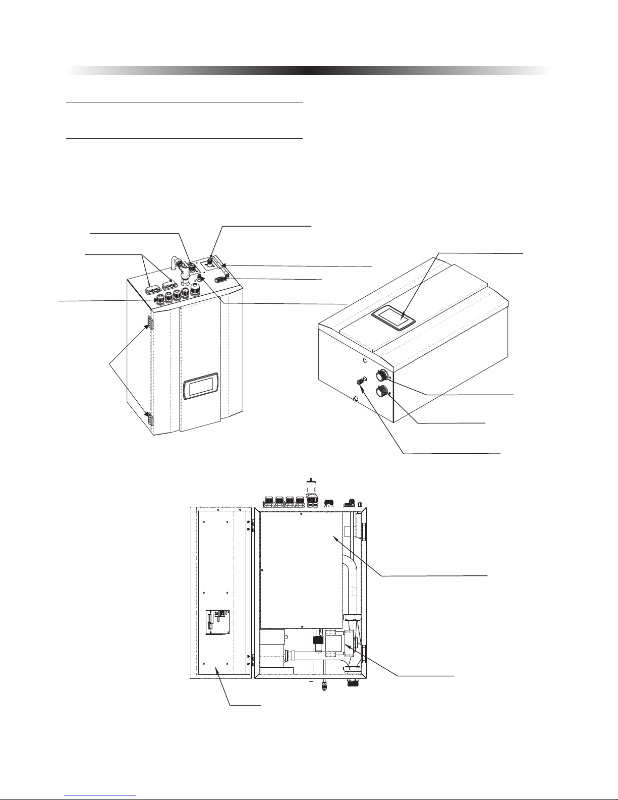
2. Overview of the Units
Indoor unit
11
2.1.Functional Diagrams
Electric Box Cover
Water Pump
Door
Wate r inlet
Wate r outle t
Air pu rgin g valve
Oper ation pan el
Refrigerant Connector
: 1 / 2"
: 5 / 8"
AWH6-V6-SW
AWH9/11/13-V6-SW
Refrigerant Connector
: 3 / 8"
: 3 / 8
"
AWH6-V6-SW
AWH9/11/13-V6-SW
Cabl e clip
Cabl e gland
Hing e
Rece iving sig nal ant enna
Sens or fixtur e
Need le valve fo r servi ce
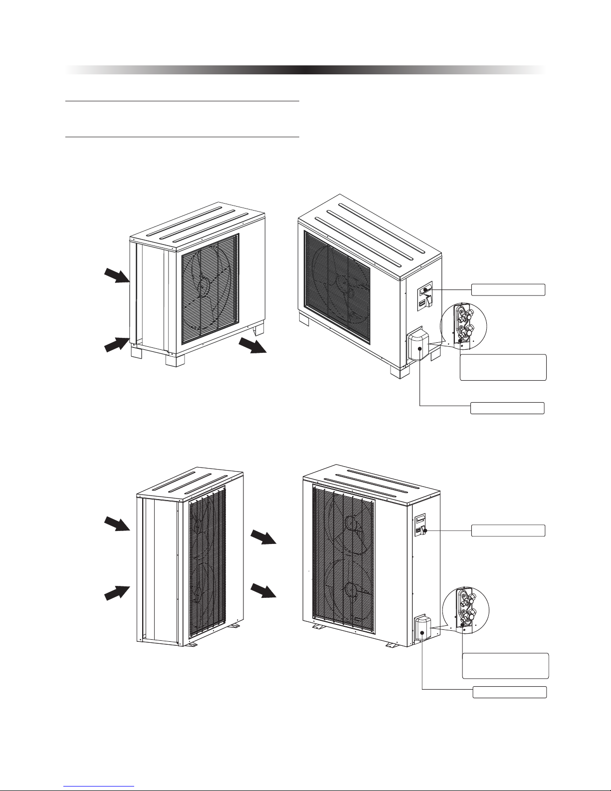
Outdoor unit
2. Overview of the Units
12
Air inlet
Air inlet
Air outlet
Valve cover
Refrigerant connector
1/2”
AW6-V6-SG
AW9-V6-SG
AW11-V6-SG
Handle
Valve cover
Refrigerant connector
5/8”
Air inlet
Air inlet Air outlet
Air outlet
Handle
2.1.Functional Diagrams
AW13-V6-SG
718.8
580.3
388.8
380
272.6
380
13
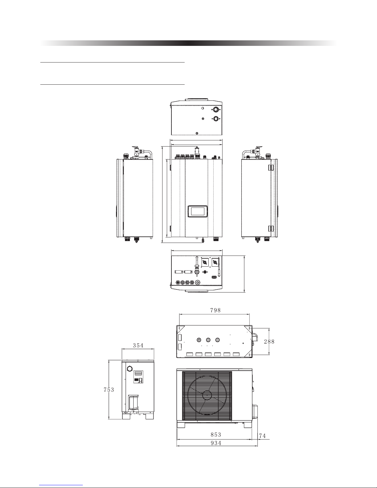
2. Overview of the Units
2.2.Outlines and Dimensions
Outlines and dimensions
Unit:mm
Indoo r ——
Outdo or ——
AW6-V6-SG
AW9-V6-SG
Unit:mm
Refrigerant connector
dimension: 1/4” and 1/
2”
AWH6-V6-SW:
AWH9-V6-SW:3/8” and 1/
2”
AWH6-V6-SW
AWH9-V6-SW
AWH11-V6-SW
AWH13-V6-SW
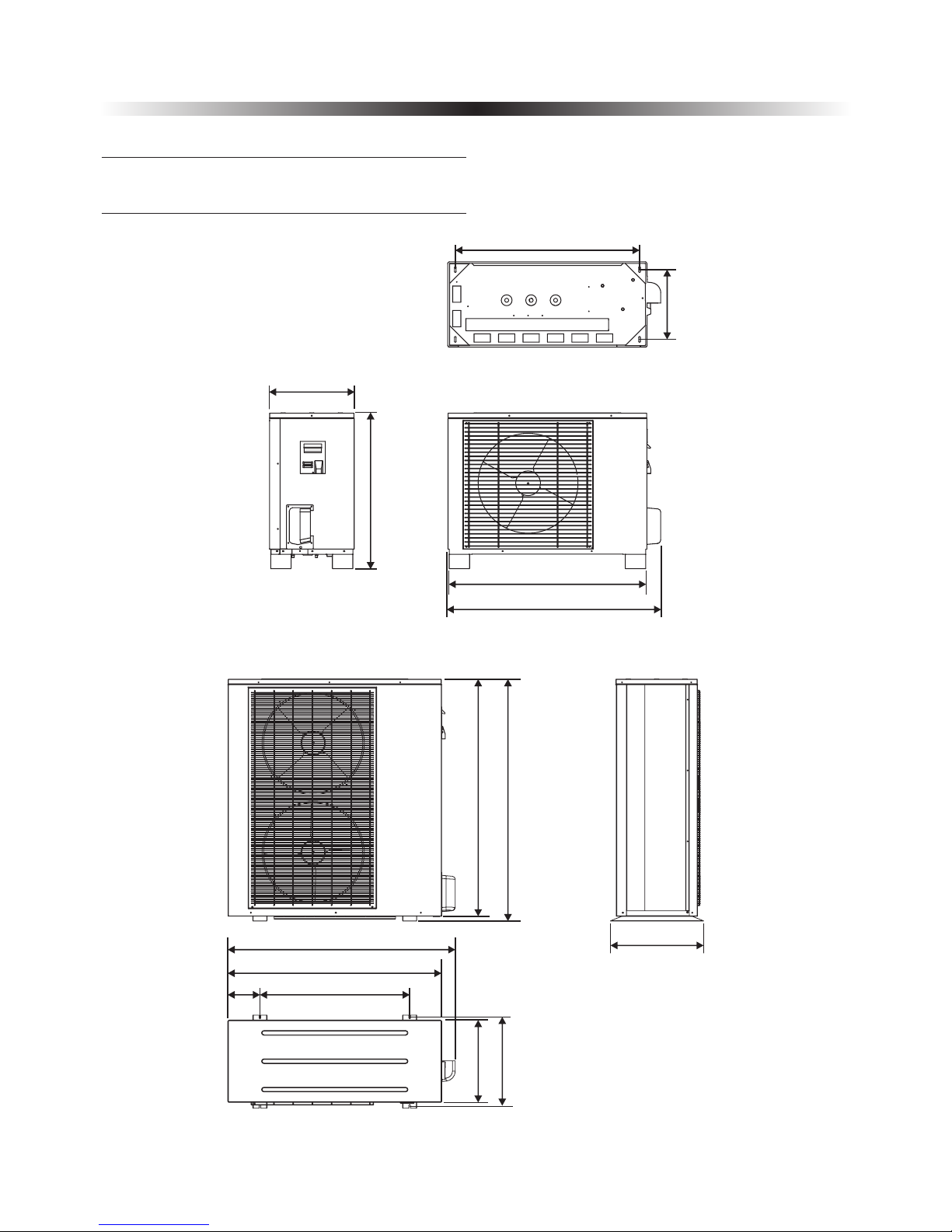
14
Refrigerant connector
dimension:3/8” and 5/8”
Unit:mm
1195
1171407
740159
1058
1124
460
Refrigerant connector
dimension:3/8” and 1/
2”
904
343
414
763
964
1044
Unit:mm
Outdo or ——
AW11-V6-SG
Outdo or ——
AW13-V6-SG
430
2. Overview of the Units
2.2.Outlines and Dimensions
15
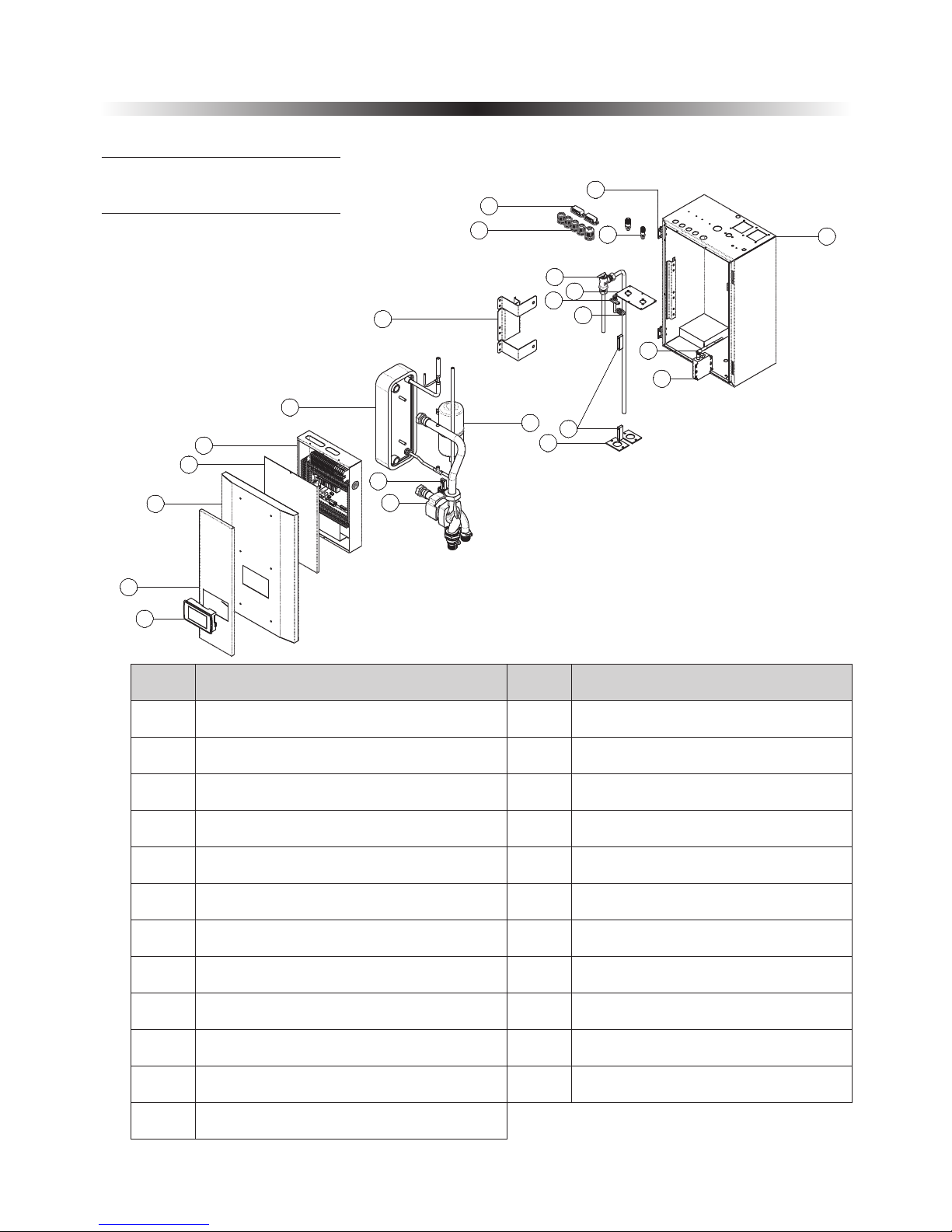
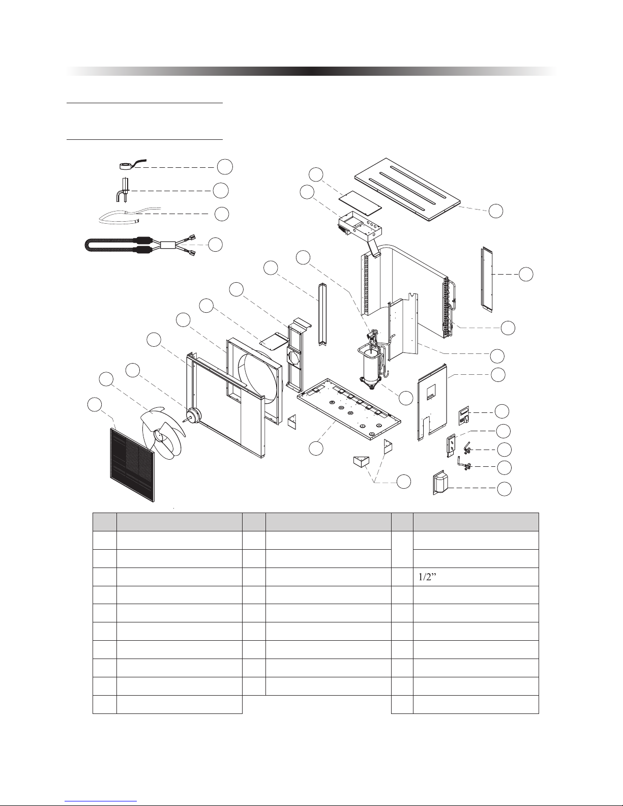
Indoo r ——AWH6-V6-SW
AWH9 -V6 -SW
AWH11 -V6-SW
1
2
3
4
5
6
7
8
9
10
11
13
14
15
16
17
18
19
20
21
22
Operation panel
Decorative panel
Door
Electric box cover
Electric box
Plate heat exchanger
Water pump
Water flow switch
Refrigerant expansion tank
Fixture of plate heat exchanger
Insulation panel
Sensor fixture
Cable gland
Refrigerant connector
Hinge
WIFI module
Receiving signal antenna
Casing
NO
Name
NO
Name
2.3. Exploded view
2. Overview of the Units
1
2
3
4
5
6
7
8
9
10
11
12
13
14
15
16
17
18
19
20
21
22
23
1 2
Magnet
23
Needle valve for service
Plate for refrigerant connector
Cable clip
Air purging valve
16
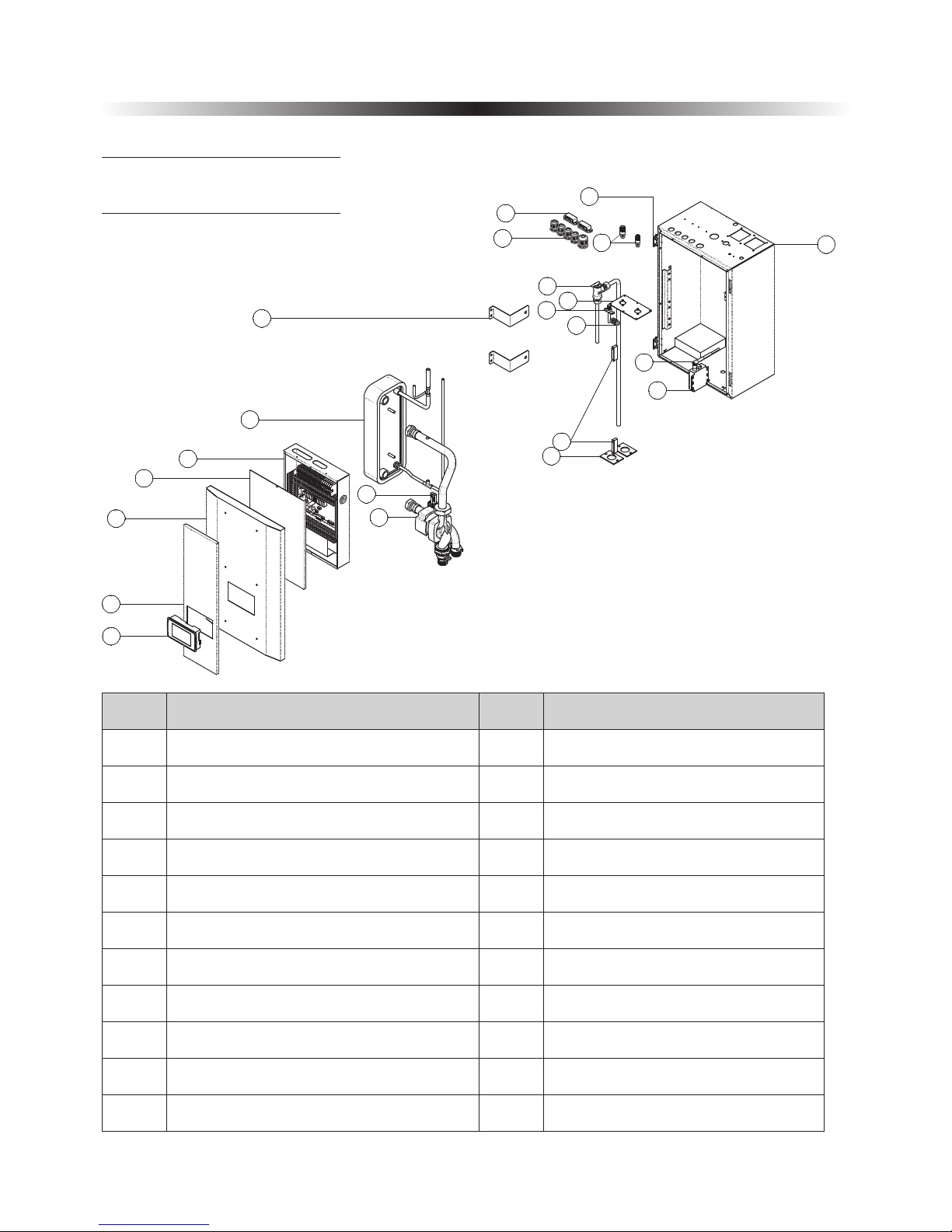
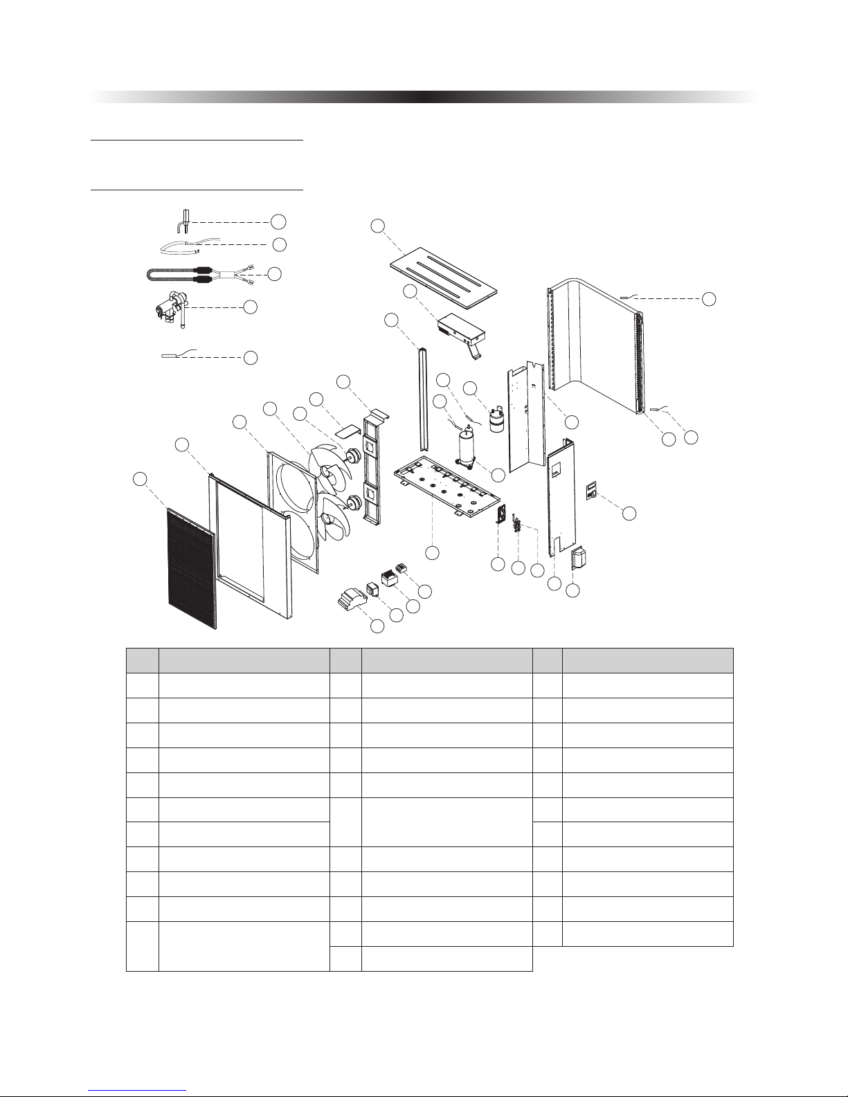
Indoo r ——AWH13-V6-SW
2.3. Exploded view
2. Overview of the Units
1
2
3
4
5
6
7
8
9
10
11
12
13
14
15
16
17
18
19
20
21
22
1
2
3
4
5
6
7
8
9
10
11
13
14
15
16
17
18
19
20
21
22
Operation panel
Decorative panel
Door
Electric box cover
Electric box
Plate heat exchanger
Water pump
Water flow switch
Fixture of plate heat exchanger
Insulation panel
Sensor fixture
Cable gland
Refrigerant connector
Hinge
WIFI module
Receiving signal antenna
Casing
NO
Name
NO
Name
1 2
Magnet
Needle valve for service
Plate for refrigerant connector
Cable clip
Air purging valve
17
Outdo or —— AW6-V6-SG
AW9- V6- SG
AW11- V6-SG
26
27
28
8
9
5
6
7
1
2
3
4
10
11
12
13
14
15
16
17
18
19
20
21
22
23
24
25
12
NO
Name
NO
Name
Decorative panel
Name
NO
13
14
15
17
18
19
20
23
24
25
26
27
28
NO NO
Fixture
Outdoor fan
Front panel
Motor bracket
Column support
Four-way valve
Air guide
Outdoor motor
1
2
3
4
5
6
7
8
9
Electrical box
Electric box cover
10
11
Top panel
Big handle
Back panel
Bulkhead
Bulkhead
3/8” -AW9/11-V6-SGValve
Condenser
Compressor
Compressor heater
Feet
Eev coil
Condebser heater
Electrical expansion valve
Bottom plate
21
22
Valve cover
Right plate
16
Valve
1/4” Valve-AW6-V6 -SG
2.3. Exploded view
2. Overview of the Units
18
Outdo or —— AW13-V6-SG
1
2
3
4
6
7
8
9
10
5
12
13
14
15
18
11
16
17
19
20
21
22
23
24
11
29
30
32
31
33
25
26
27
28
13
NO
Name
NO
Name
Decorative panel
Name
NO
14
15
16
17
18
19
20
21
25
26
27
28
29
30
NO NO
Fixture
Front panel
Outdoor fan
Motor bracket
Column support
Controller
Outdoor motor
Air guide
31
32
1
2
3
4
5
6
7
8
9
Top panel
Coil and ambient
temperature sensor
Condenser
10
11
12
22
33
Bulkhead
Compressor
Handle
Suction temperature sensor
Bottom plate
Valve plate
5/8” Valve
Compressor discharge
temperature sensor
Sperator
3/8” Valve
Terminal block
Crankcase heater
PFC transducer
EEV controller
Condenser heater
4-Way valve
Electronic expansion valve
Transformer
EEV temperature sensor
23
24
Side panel
Valve cover
2.3. Exploded view
2. Overview of the Units
19
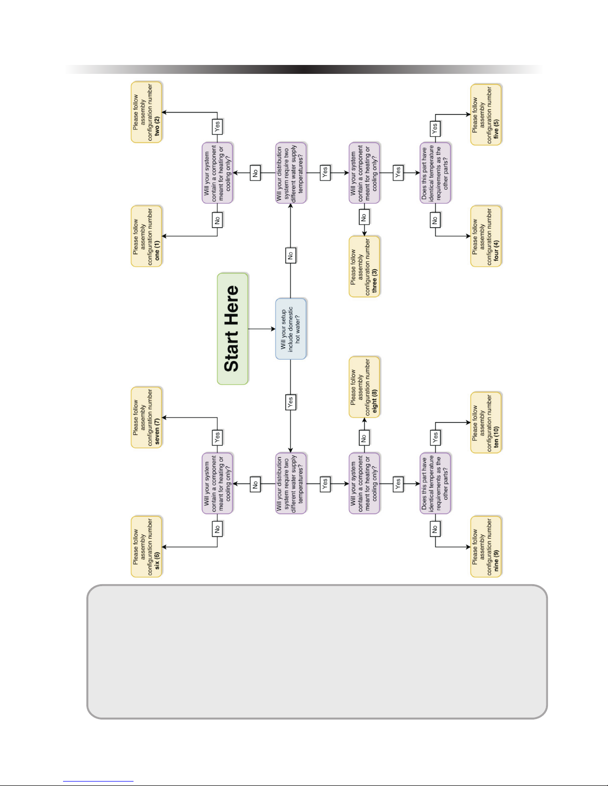
3. Assembly Configurations - Flowchart
Locate the Configuration that Meets Your Needs
Follow the flowchart on
the right in order to locate
which of the assembly
configuration matches the
needs of the end user,
each of which contains
specific assembly and
wiring diagrams, with
software instructions.
Beginning from the green
“Start Here” bubble,
follow the appropriate
arrows to each question,
which are dependent on
the needs of the user.
The corresponding
assembly instructions will
be found by turning to the
page number in the end
bubble.
Note: The instructions in this
section are meant to achieve
the minimum requirements for
successful system operation
only.
For more in-depth settings
explanations, please refer to
the user′s manual.
20
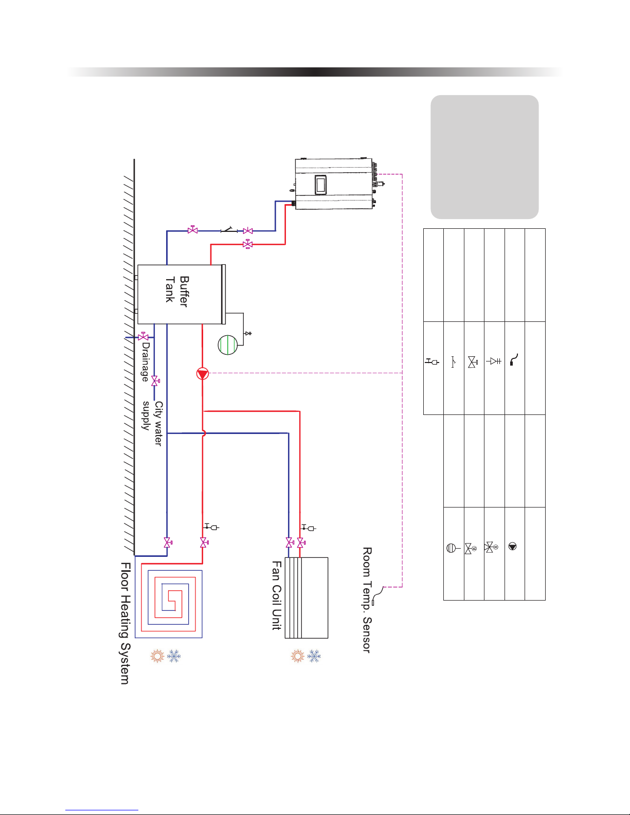
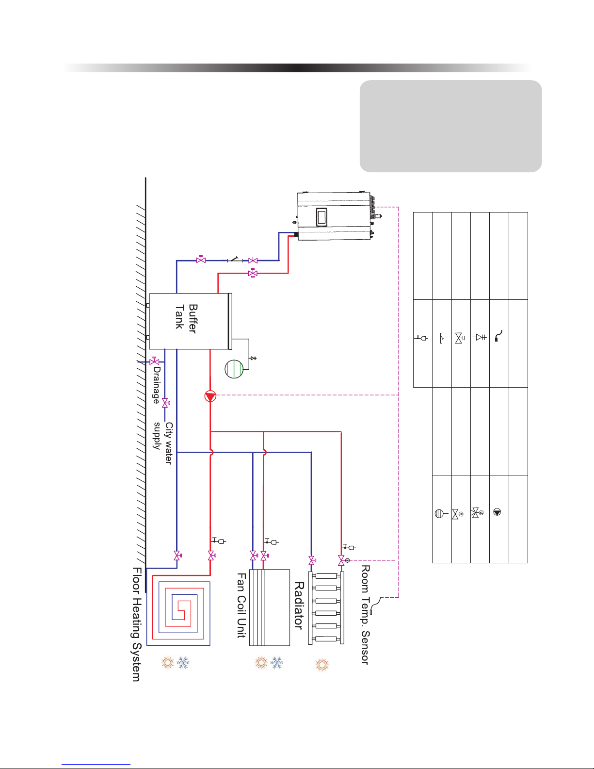
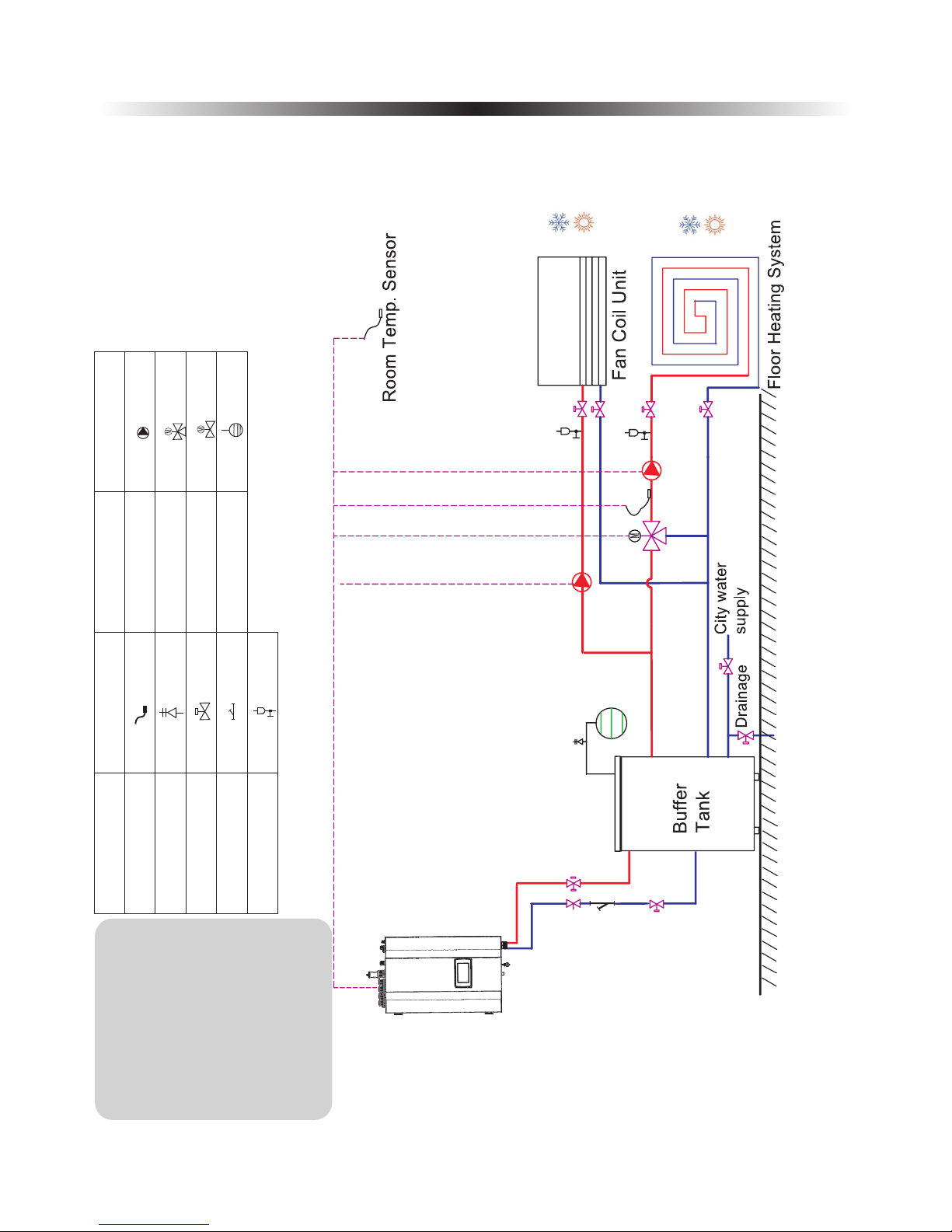
3. Assembly Configurations - Drawing 1
Notice: The Fan Coil Unit,
Floor Heating System, and
Radiator are placeholder
distribution systems only
and can be substituted by
any other appropriate
distribution systems.
Please ensure that the
configuration matches the
assembly drawing depicted
on the right for a one
temperature zone without
domestic hot water setup.
Note: Refer to the next page for
wiring and software
operation instructions.
Nam e
Sym bol
Nam e
Sym bol
Temp.Sen so r
Safety v al ve K it
Ball valve
Wat er f il te r
Air purg in g va lv e
Wat er p um p
Mixing v al ve
Motori ze d val ve
Expans io n ta nk
Note: Do tt ed l in es mean〝abl e to b e co nt ro ll ed by the Hea t Pu mp〞.
One Temperature Zone ,without DHW
21
3. Assembly Configurations - Drawing 1
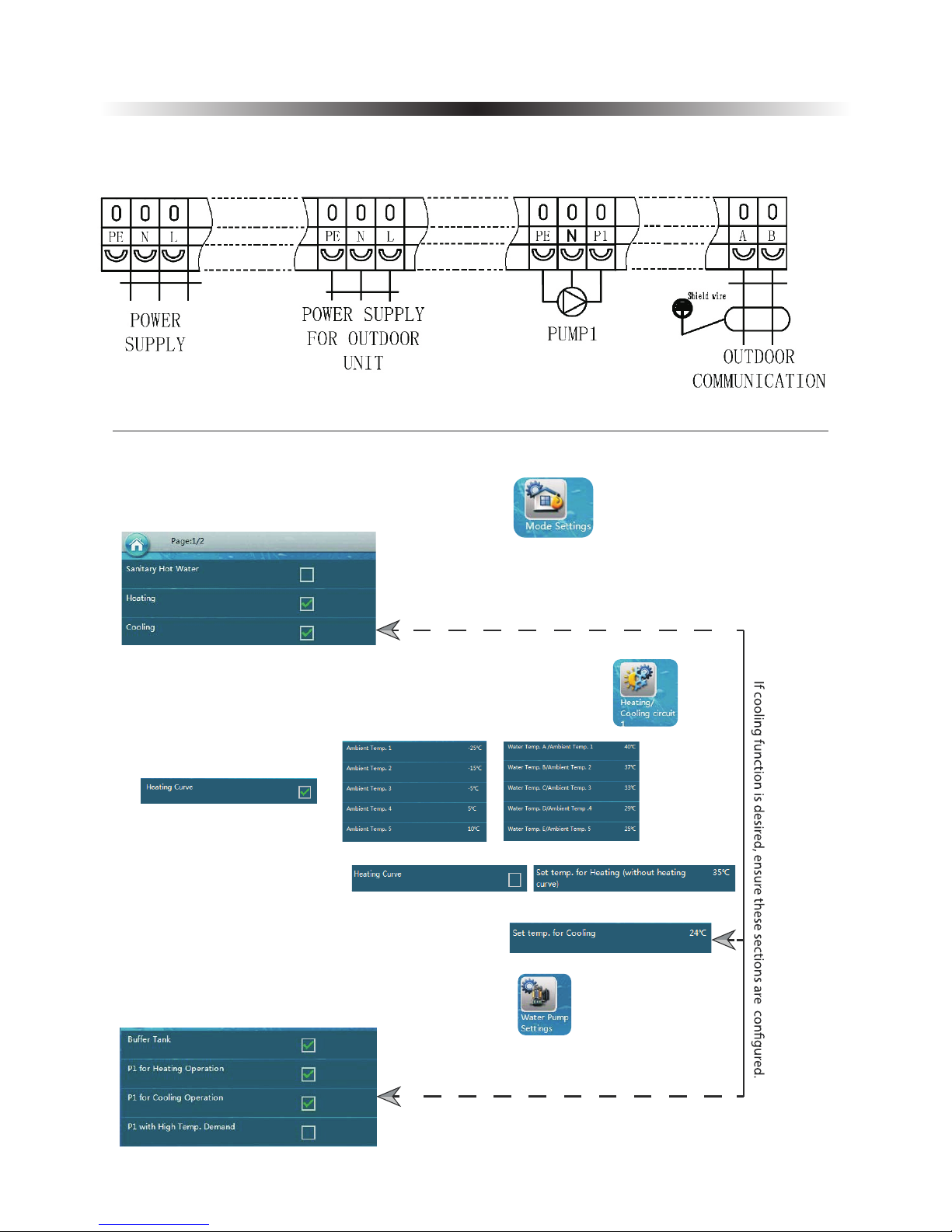
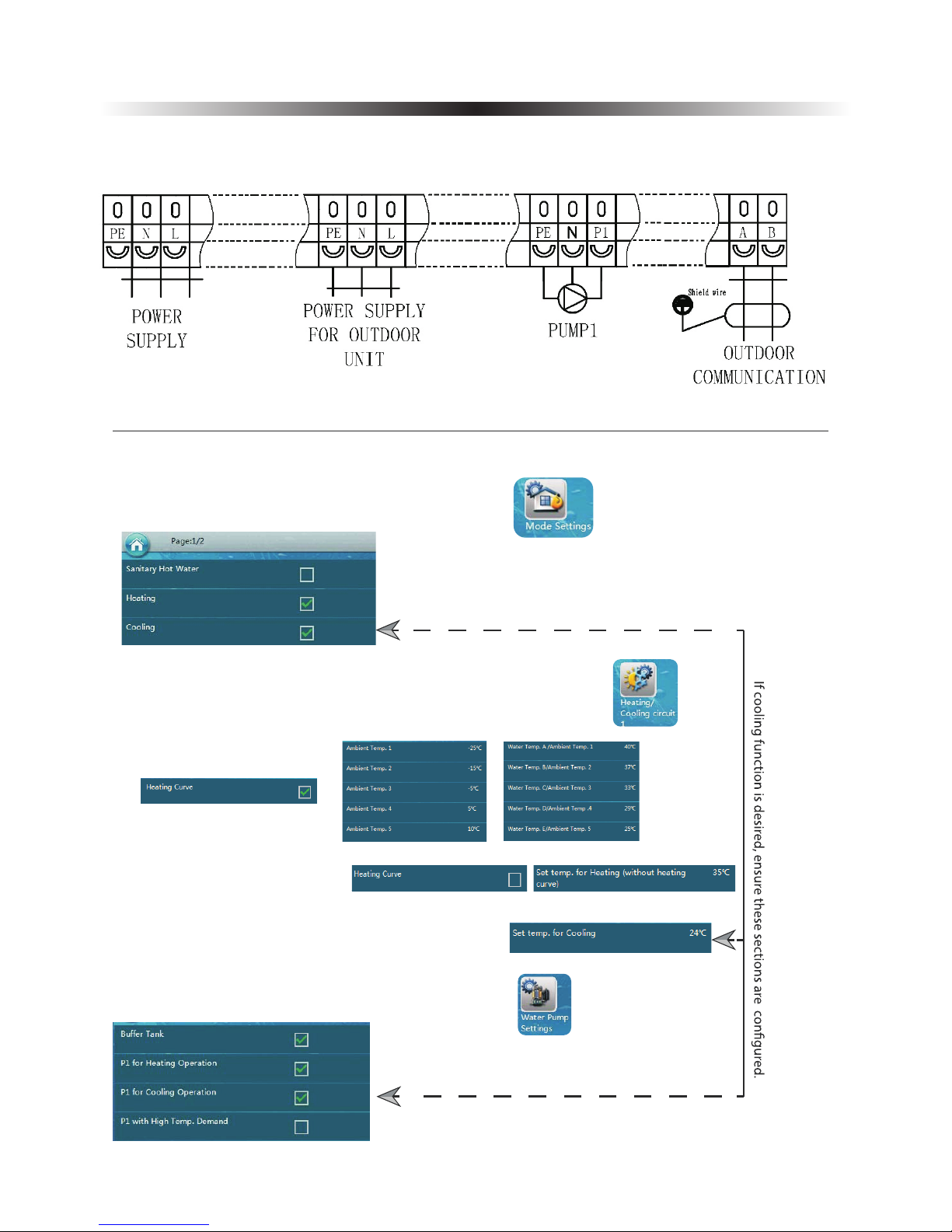
Assembly 1: Wiring Diagram
To achieve successful operation at a minimum, ensure the ports below are properly connected.
Software: Basic Settings
1.Se t the nee ded wor king mo des of th e unit vi a the men u
H.2. If no heating curve is desired:
3.Locate and activate the buffer tank and appropriate pumps under
H.1.Setting a heating curve:
H.Configuring the set water heating temperatures:
2.Temperatur e confi gurat ion opt ions fo r Heati ng/Co oling c ircui t 1 are found under
C.Co nfigu ring th e set wat er cool ing tem perat ure (if a pplicable):
22
3. Assembly Configurations - Drawing 2
Notice: The Fan Coil Unit,
Floor Heating System, and
Radiator are placeholder
distribution systems only
and can be substituted by
any other appropriate
distribution systems.
Please ensure that the
configuration matches the
assembly drawing depicted
on the right for a one
temperature zone without
domestic hot water setup,
that includes a component
circuit capable of heating or
cooling only,through the use
of a two-way motorized
valve.
Note: For the cooling-only or
heating-only circuit, a
motorized two-way valve
can be connected to the
unit, to cut the water
supply during heating or
cooling operation.
Refer to the next page for
wiring and software
operation instructions.
Nam e
Sym bol
Nam e
Sym bol
Temp.Sen so r
Safety v al ve K it
Ball valve
Wat er f il te r
Air purg in g va lv e
Wat er p um p
Mixing v al ve
Motori ze d val ve
Expans io n ta nk
Note: Do tt ed l in es mean〝abl e to b e co nt ro ll ed by the Hea t Pu mp〞.
One Temperature Zone ,without DHW,with a heating-only
(or cooling-only) circuit,by usage of a motorized 2-way valve
23
3. Assembly Configurations - Drawing 2
Assembly 2: Wiring Diagram
To achieve successful operation at a minimum, ensure the ports below are properly connected.
Software: Basic Settings
1.Se t the nee ded wor king mo des of th e unit vi a the men u
H.2. If no heating curve is desired:
3.Locate and activate the buffer tank and appropriate pumps under
H.1.Setting a heating curve:
H.Configuring the set water heating temperatures:
2.Temperatur e confi gurat ion opt ions fo r Heati ng/Co oling c ircui t 1 are found under
C.Co nfigu ring th e set wat er cool ing tem perat ure (if a pplicable):
24
3. Assembly Configurations - Drawing 2
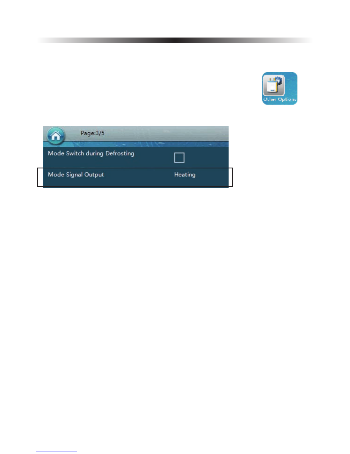
Software: Basic Settings (continued)
4.The location of the configuration for heating-only or cooling-only system is under
25
3. Assembly Configurations - Drawing 3
Nam e
Sym bol
Nam e
Sym bol
Temp.Sen so r
Safety v al ve K it
Ball valve
Wat er f il te r
Air purg in g va lv e
Wat er p um p
Mixing v al ve
Motori ze d val ve
Expans io n ta nk
Note: Do tt ed l in es mean〝abl e to b e co nt ro ll ed by the Hea t Pu mp〞.
Notice: The Fan Coil Unit,
Floor Heating System,and
Radiator are placeholder
distribution systems only
and can be substituted by
any other appropriate
distribution systems.
Please ensure that the
configuration matches
the assembly drawing
depicted on the right for
a two temperature zone
without domestic hot
water setup.
Note: Refer to the next page
for wiring and
software operation
instructions.
Two Temperature Zones ,without DHW
 Loading...