

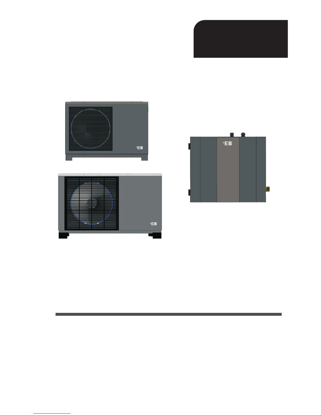
Heat Pump
DC Inverter Air to Water
Before operating this product, please read the
instructions carefully and keep this manual for future use.
User’s manual
User’s manual
AWH9/11-V5+
MBG series

2

1. Before use
1.1 Safety precautions
1.2 Working principle
1.3 Main components
1.4 Specifications
2. Installation
2.2 Tools needed
2.3 Installation of the indoor control unit
2.4 Installation of the monoblock unit
2.5 Accessories
2.6 Wiring
2.7
2.8
2.9
3. Usage
3.1 Introduction of wired controller
3.2 Parameter setting overview
3.6
4. Maintenance
4.1 Attention
4.5
4.6
4.7
4.8 Trouble-shooting
5.
5.1 Outlines and dimensions
5.2 Exploded view
5.3 Wiring diagram
2.1 General application system introduction
Installation of safety valve kit
3.3 Basic operation
4.2 Cleaning of water filter
4.3 Cleaning of plate heat exchanger
4.4 Gas charging
Condenser coil
Service of indoor control unit
Service of monoblock unit
Water pipe connection
Test run
3.4 Advanced setting
3.5 Failure code
Error code
Attached drawing
4
4
6
7
8
11
11
13
13
15
17
18
25
26
27
28
28
30
35
47
58
59
68
68
68
68
68
69
69
72
76
78
78
81
83
Catalogue
3
1. Before use
CautionWarning
Prohibition
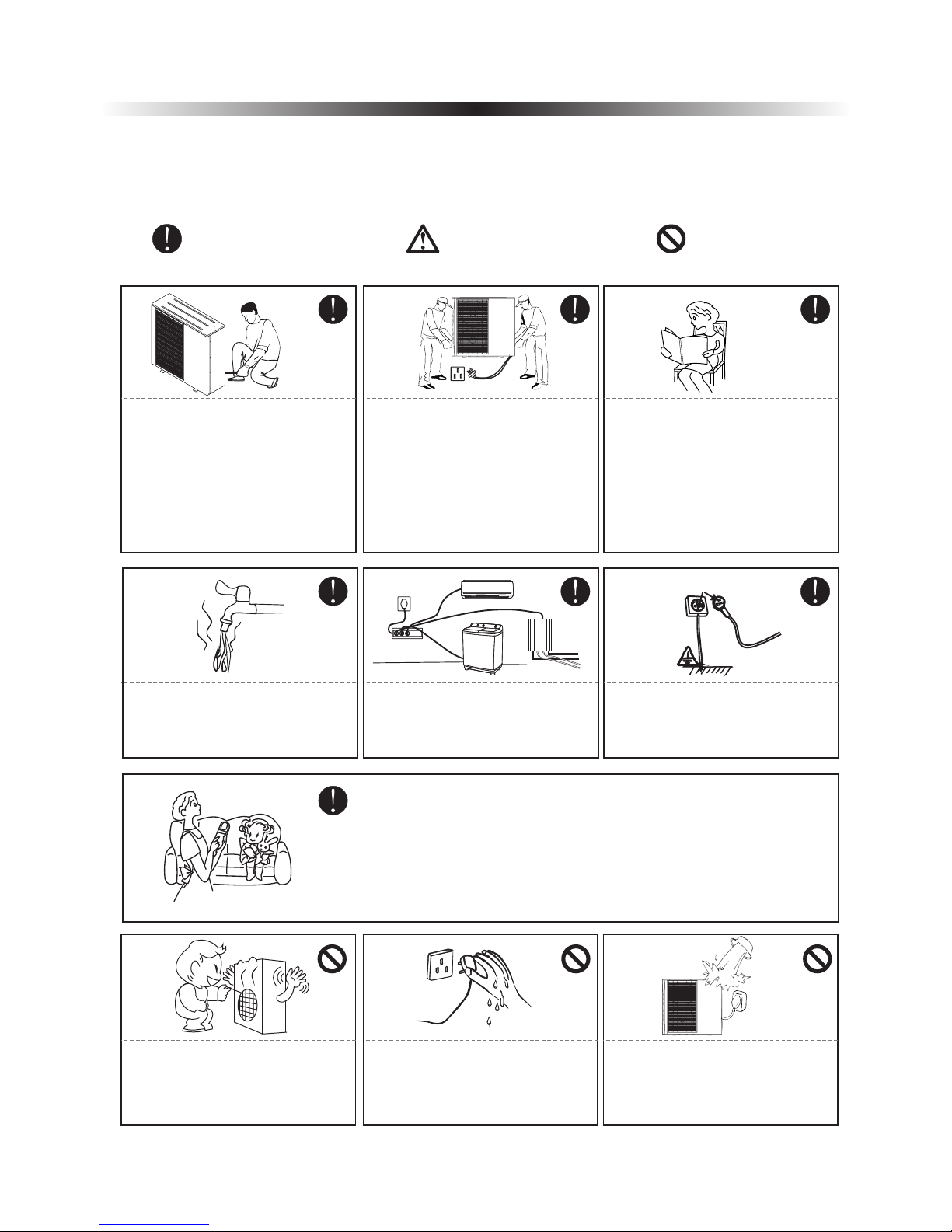
1.1 Safety precautions
The following symbols are very important. Please be sure to understand their meaning, which concerns
the product and your personal safety.
The installation, dismantlement
and maintenance of the unit must
be performed by qualified
personnel. It is forbidden to do any
changes to the structure of the unit.
Otherwise injury of person or unit
damage might happen.
To avoid electrical shock, make
sure to disconnect the power
supply 1 minute or more before
servicing the electrical parts. Even
after 1 minute, always measure the
voltage at the terminals of main
circuit capacitors or electrical parts
and, before touching, make sure
that those voltages are lower
than the safety voltage.
User Ma nual
Be sure to read this manual before
use.
For sanitary hot water, please
always add a mixture valve before
water tap and set it to proper
temperature.
Ground wire
Use a dedicated socket for this
unit, otherwise malfunction may
occur.
The power supply to the unit must
be grounded.
Do not touch the air outlet grill
when fan motor is running.
Do not touch the power plug with
wet hands. Never pull out the plug
by pulling the power cable.
Water or any kind of liquid is
strictly forbidden to be poured into
the product, or may cause electric
creepage or breakdown of the
product.
This appliance can be used by children aged from 8 years and above
and persons with reduced physical, sensory or mental capabilities or
lack of experience and knowledge if they have been given supervision
or instruction concerning use of the appliance in a safe way and
understand the hazards involved. Children shall not play with the
appliance. Cleaning and user maintenance shall not be made by
children without supervision.
4
1. Before use
Copper
Steel
Fuse
Main
Power Cable
RCD
Indoor
control
unit
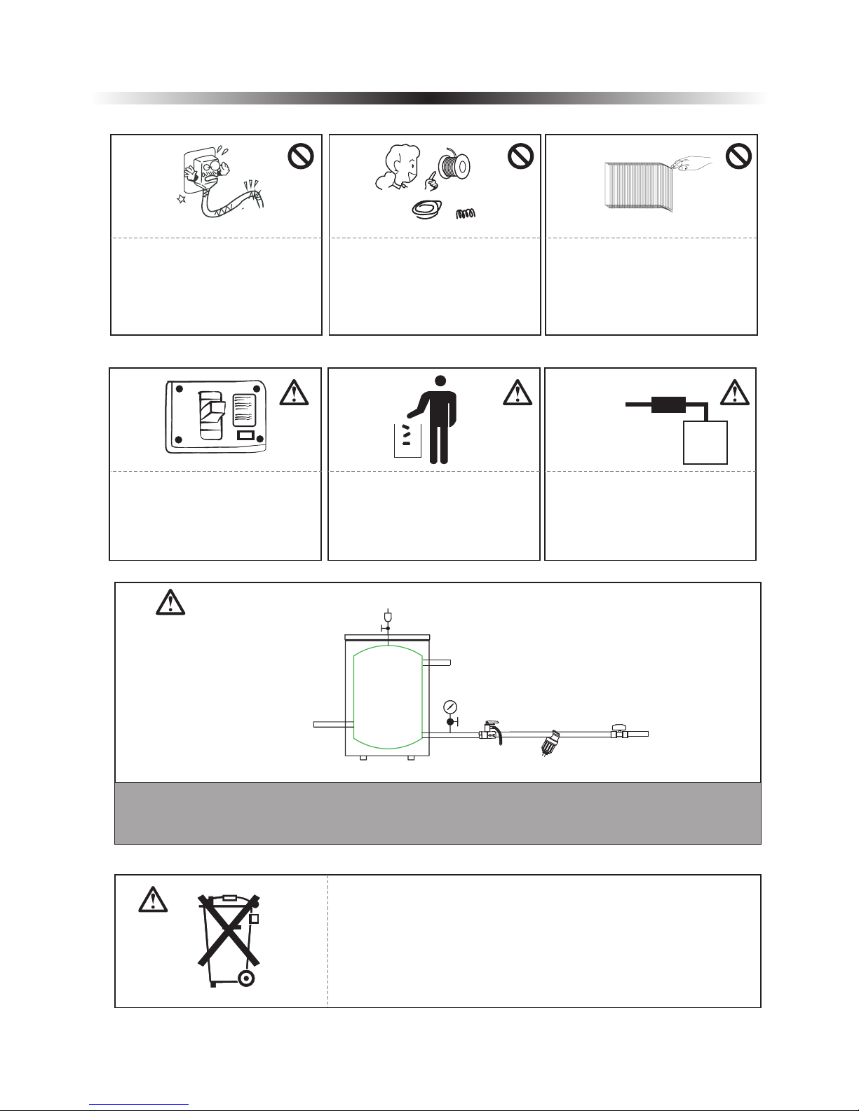
When the power cord gets loose
or damaged, always get a qualified
person to fix it.
It is mandatory to use a suitable
circuit breaker for the heat pump
and make sure the power supply to
the unit corresponds to the
specifications. Otherwise the unit
might be damaged.
Disposal of Scrap Batteries(if
there is).Please discard the
batteries as sorted municipal waste
at the accessible collection point.
Installation of a residual current
device (RCD) having a rated
residual operating current not
exceeding 30 mA is advisable.
ON
OFF
Please select the correct fuse or
breaker as per recommended. Steel
wire or copper wire cannot be
taken as substitute for fuse or
breaker. Otherwise, damages
maybe caused.
Be aware fingers might be hurt by
the fin of the coil.
5
This marking indicates that this product should not be disposed with
other household wastes throughout the EU. To prevent possible harm to
the environment or human health from uncontrolled waste disposal,
recycle it responsibly to promote the sustainable reuse of material
resources. To return your used device, please use the return and
collection systems or contact the retailer where the product was
purchased. They can take this product for environmental safe recycling.
System water filling
T/P valve
Connect to heating/cooling system
Buffer tank
Connect to heat pump
One way valve
Filter
City water inlet
1. It's suggested to use pure water for filling the system.
2. If use city water for filling, please soften the water and add a filter.
Note: After filling, the system of water system should be 0.15~0.6MPa.
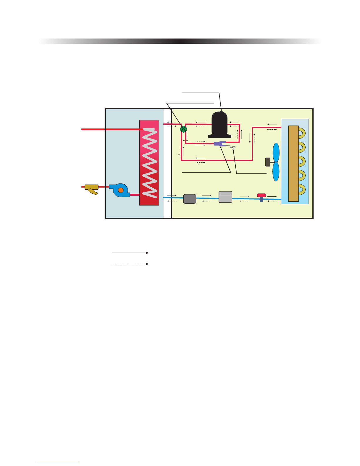
1.2 Working principle
1. Before use
Water inlet
Water Outlet
Filter
Water pump
Heat
exchanger
Power supply
Four-way vavle
Compressor
Three-way valve
Refrigerant Filter
T-connector
Fan motor
Pressure
check valve
Evaporator
Heating
Cooling
6
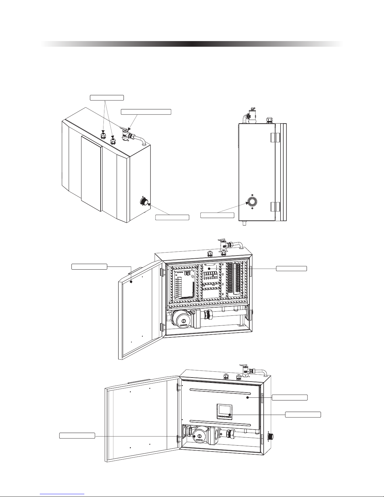
Operation panel
Cable gland
Water outlet
Water inlet
1.3 Main components
1. Before use
1.3.1 Indoor control unit
7
Press ur e Re li ef Valves
Electric box
Door
Electric box cover
Water pump
1.3.2 Monoblock unit
1. Before use
8
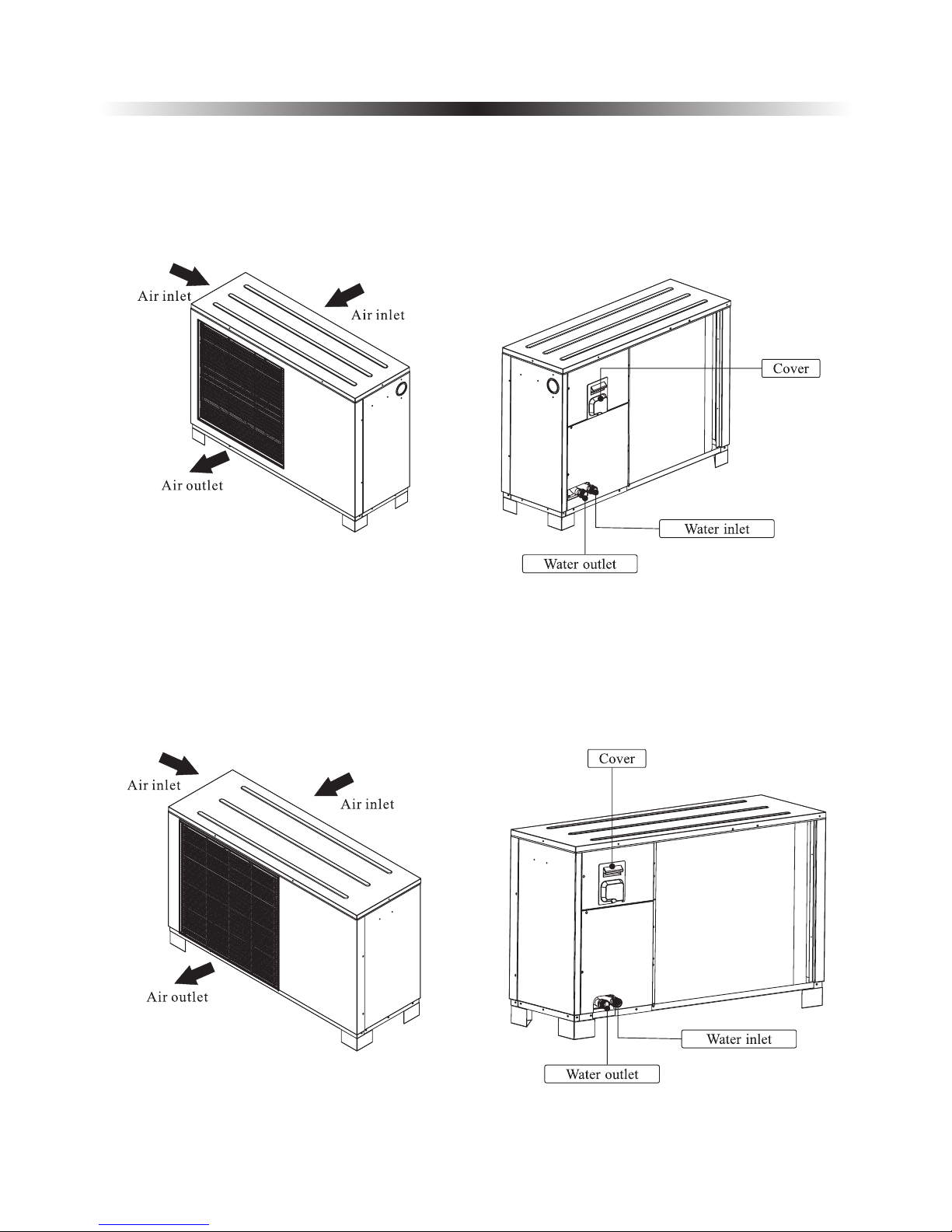
AW9-V5+
AW11-V5+
1. Before use
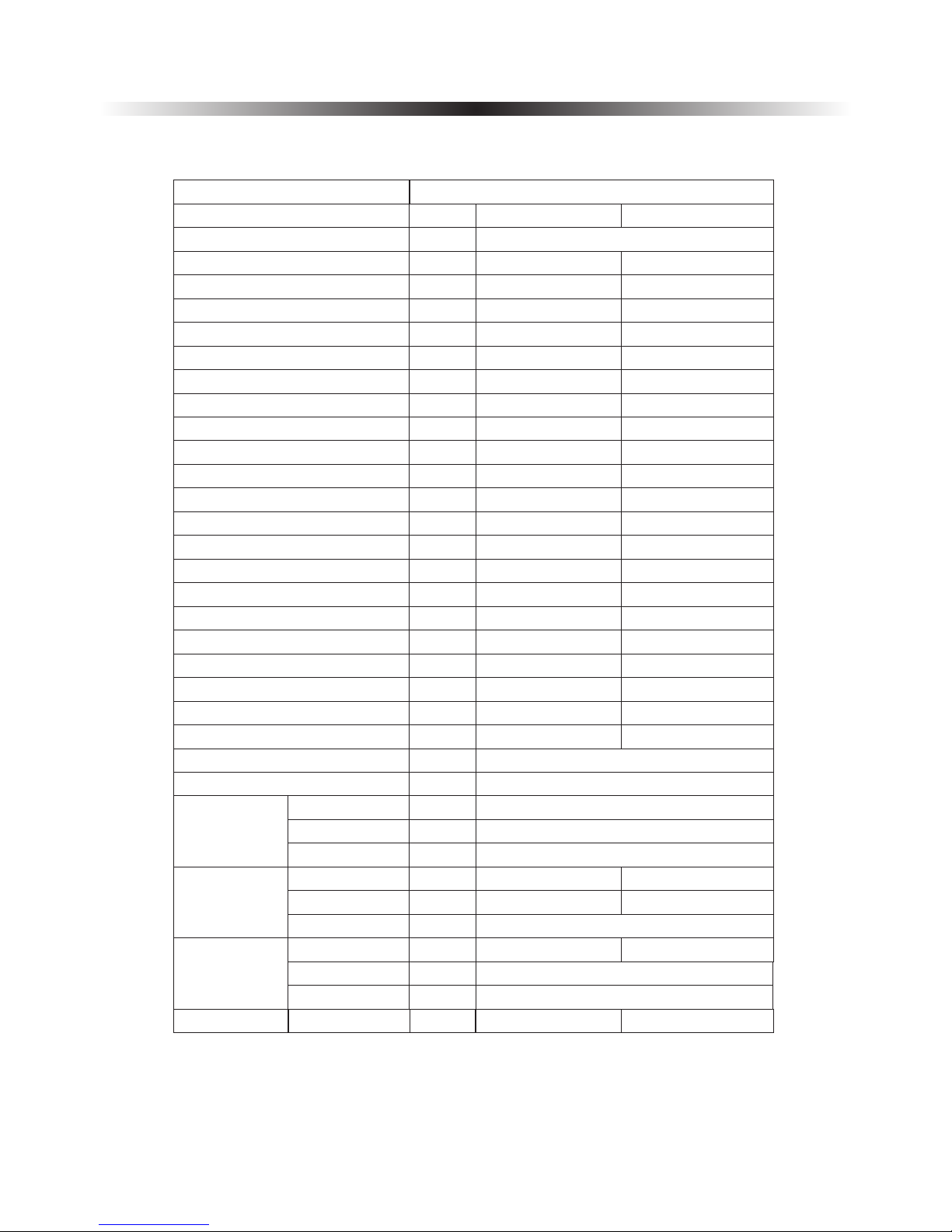
1.4 Specifications
9
Model
Power Supply
V/Hz/Ph
AWH11-V5+
AWH9-V5+
220-240/50/1
Refrigerant
Max. Heating Capacity (1)
C.O.P (1)
Heating Capacity Min./Max.(1)
Heating Power Input Min./Max.(1)
C.O.P Min./Max.(1)
Max. Heating Capacity(2)
C.O.P (2)
Heating Capacity Min./Max.(2)
Heating power input Min./Max.(2)
C.O.P Min./Max.(2)
Max. Cooling Capacity(3)
E.E.R (3)
Cooling Capacity Min./Max.(3)
Cooling Power Input Min./Max.(3)
E.E.R Min./Max.(3)
Max. Cooling Capacity(4)
E.E.R(4)
Cooling Capacity Min./Max.(4)
Cooling Power Input Min./Max.(4)
E.E.R Min./Max.(4)
KW
W/W
KW
W
W/W
KW
W/W
KW
W
W/W
KW
W/W
KW
W
W/W
KW
W/W
KW
W
W/W
11.510.10
3.824.03
4.67/11.5
4.33/10.10
915/3029
975/2153
3.82/5.05
4.02/4.65
10.7
9.53
2.95
3.17
4.14/10.74.19/9.53
1218/36241230/2990
2.95/3.563.12/3.55
9.2
6.84
2.682.09
4.33/9.24.10/6.84
993/3465
1230/3280
2.685/4.11
2.09/3.32
6.745.05
2.15
1.58
2.17/6.742.34/5.05
924/31321080/3200
2.15/3.01.58/2.40
R410A/1.9
R410A/2.45
Circuit Max. Pressure
bar
42
Rated Power Water Pump
W
Compressor
Type
Quantity/System
Twin Rotary
1
Oil
Fan
Quantity
Airflow
Rated Power
m³/h
W
31003000
60
1
1
Allowable
Fan Flow
Face Area
Row-Fins/Inch
Tube.Dia
m²
Inch
0.8710.542
Kg
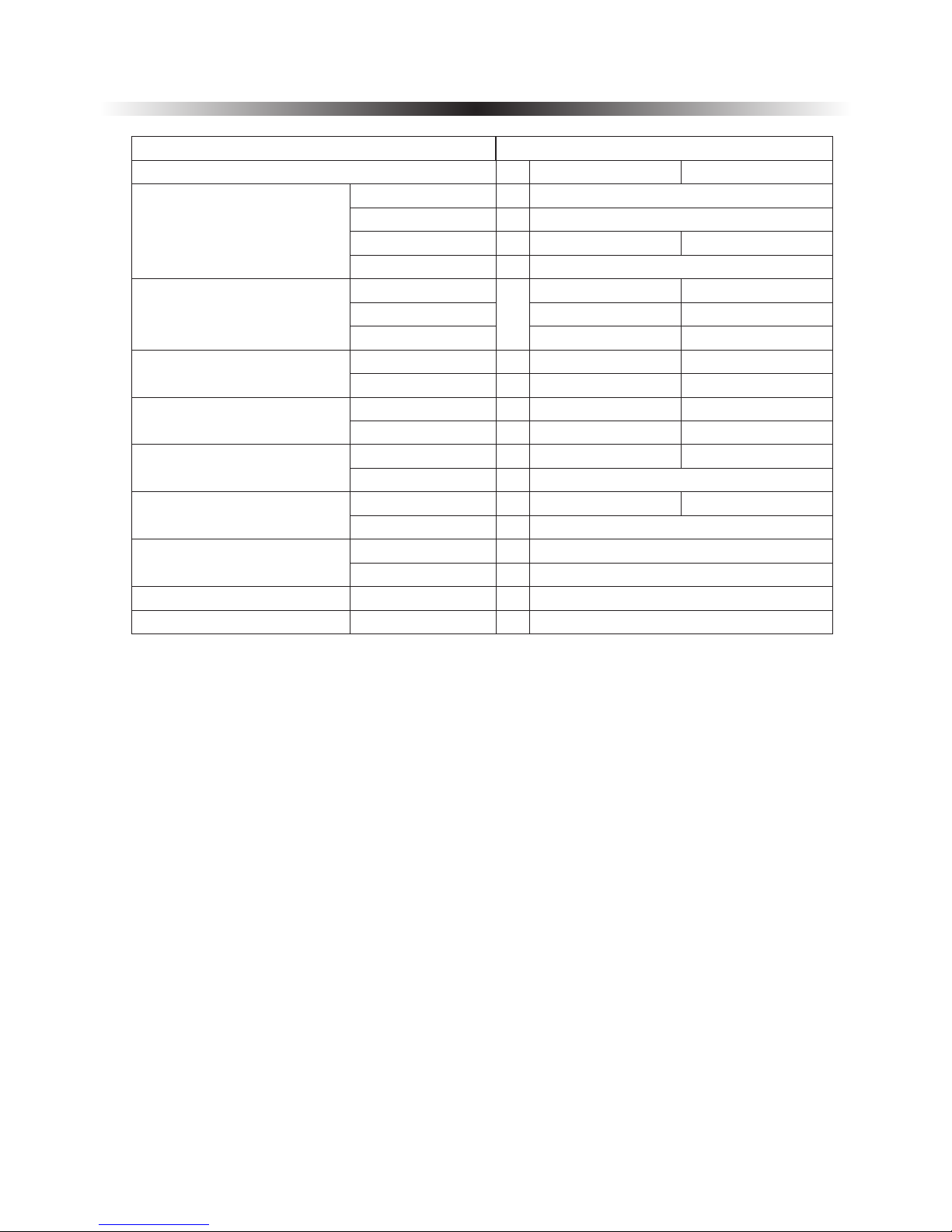
Type of Product
DC Inverter Air to Water Heat Pump Unit
Noise Level
Indoor/Outdoor
30/56
dB(A)
87
FV50S
3/8 O.D
2 Rows-14
30/56
1. Before use
10
NOTE:
(1) Heating condition: water in/out temperature:30℃/35℃, ambient temperature:DB/WB 7/6℃;
(2) Heating condition: water in/out temperature:40℃/45℃, ambient temperature:DB/WB 7/6℃;
(3) Cooling condition: water in/out temperature:23℃/18℃, ambient temperature:35℃;
(4) Cooling condition: water in/out temperature:12℃/7℃, ambient temperature:35℃.
(5) The specifications are subject to change without prior notice.
For actual specifications of the unit, please refer to the specification stickers on the unit.
Net Dimension (L×D×H)
Packing Dimension (L×D×H)
Net Weight
Packing Weight
Outdoor Unit
Indoor Unit
Outdoor Unit
Indoor Unit
Outdoor Unit
Indoor Unit
Outdoor Unit
Indoor Unit
1215×415×7601064×353×754
500 495 210× ×
1310× ×830520
1130 460 904× ×
94
20
81
98
86
Water Side Heat Exchanger
Allowable Water Flow
Type
Water Pressure Drop
Piping Connection
Min. Water Flow
Rated Water Flow
Max. Water Flow
23
G1”
0.520.43
0.310.26
0.620.51
Material
Heating
Cooling
Operating Ambient Temp. range
Operating Inlet Water Temp. range
Water Volume
mm
mm
mm
mm
Kg
Kg
Kg
Kg
Kpa
Inch
L/S
℃
℃
℃
Kg
18
-25~46
0~55
7~75
4.5
Plate Heat Exchanger
Stainless Steel+Copper
Model
Type of Product
DC Inverter Air to Water Heat Pump Unit
23
600×520×260
AWH9-V5+ AWH11-V5+
500 495 210× ×
600×520×260
2. Installation
11
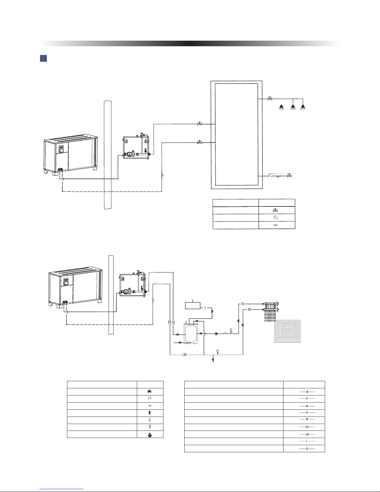
2.1 Application system introduction
To city water
Wate r disch arge outlet
De 25
De 3 2
De 3 2
De 40
De 4 0
De 2 5
De 2 5
De 3 2
De 3 2
UP S 2 5 / 8 0
热水 出 水
口G1
"
生活热
水补 水
口
G1
"
G1
"
G1
"
AH
-
2
00
L
40
~
5
0℃
Application 1: Sanitary hot water
Hot wa ter outle t
City water inlet
Application 2: Floor heating system
Name
Drawing
Ball valve
One way valve
Filter
Drain outlet
30L buff er t ank
Floor heatin g
distributi on sy ste m
Name
Drawing
Ball valve
One way valve
Filter
Safe valve
Air discharge valve
Water pressure gauge
Motor three way valve
Refrigerant pipe
Hot water outlet pipe
Hot water inlet
Heating water outlet pipe
Heating water inlet pipe
Cooling/heating water outlet pipe
Cooling/heating water inlet pipe
City water inlet pipe
Sanitary hot water outlet pipe
Name
Drawing
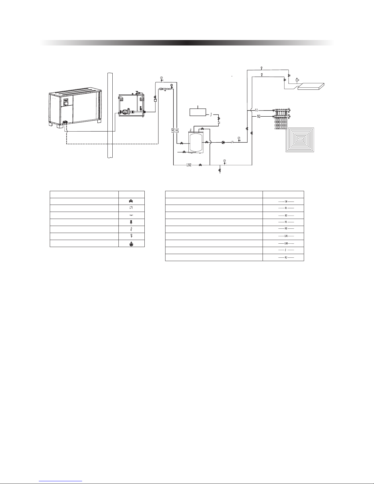
2. Installation
12
De 3 2
De 3 2
De 4 0
De 4 0
De 2 5
De 2 5
De 3 2
De 3 2
UP S 2 5 / 8 0
12
11
9
10
Application 3: Heating and cooling system
Fan coil unit
Floor heatin g
distributi on sy ste m
To city water
Drain outlet
30L buff er t ank
Wate r disch arge outlet
De 25
Name
Drawing
Ball valve
One way valve
Filter
Safe valve
Air discharge valve
Water pressure gauge
Motor three way valve
Refrigerant pipe
Hot water outlet pipe
Hot water inlet
Heating water outlet pipe
Heating water inlet pipe
Cooling/heating water outlet pipe
Cooling/heating water inlet pipe
City water inlet pipe
Sanitary hot water outlet pipe
Name
Drawing
The installation of the product should be handled by professional installers or under their
instructions.
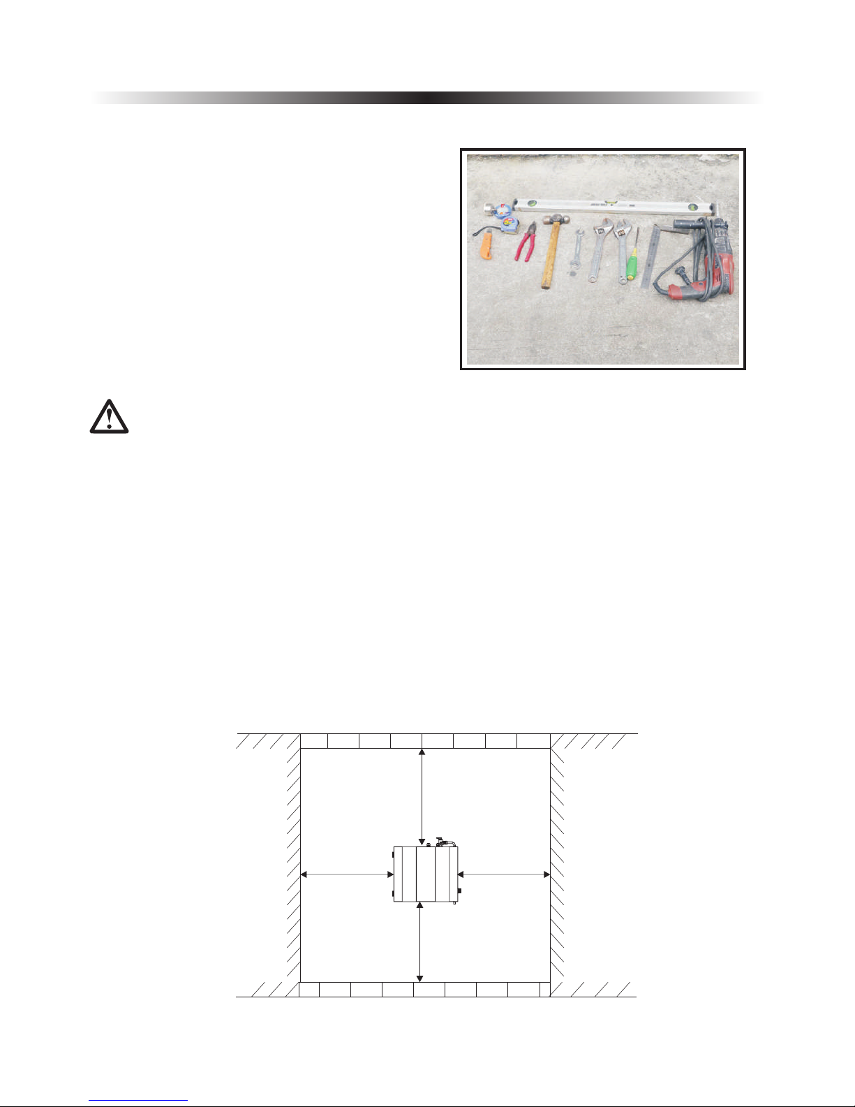
>500mm
>100mm >100mm
>500mm
2. Installation
2.2 Tools needed
2.3 Installation of the indoor control unit
Most people already have the tools needed for
installation: spirit level, pencil, crosshead
screwdriver, drill, 8 mm. concrete drill bit, detection
drill, square, tape measure or ruler, tape width 65
mm, hole saw about 80 mm (deviation in size may
occur), knife and two adjustable spanners or pliers
(and possibly torque wrench).
2.3.1 Installation notes
1)
2) The indoor unit shall be placed in dry and well-ventilated environment.
3) Indoor unit mustn't be installed in an environment where volatile, corrosive or flammable liquid
or gas exists.
4)
The indoor control unit should be installed indoors and mounted on the wall, with water outlet
downwards.
control
control
control
Please choose a suitable position to install the indoor control unit as follows:
Enough space should be left around the indoor unit for futher maintenance.
13
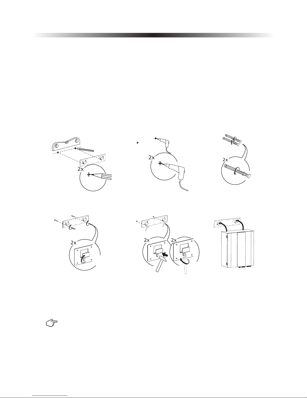
2.3.2 Installation
Indoor unit should be mounted on the wall as per procedures below:
1) Take out the expansion bolts and mounting board from accessory and put the mounting board on the
wall horizontally; Mark on the wall the location for bolts through the holes on mounting board.
2) Drill holes with proper diameter for expansion bolts.
3)
4)
5)
6) Hang the indoor unit onto the mounting board and make sure it's placed well before you let go
your hands. The installation is finished.
control
Unscrew the nuts out from the expansion bolts.
Fix the mounting board on the expansion bolts a little bit, but don't be too tight.
Use a hammer to pound the expansion bolts into the drilled holes. Fasten the nuts by turning the wrench
to fix the mounting board on the wall.
control
2. Installation
1
2 3
4
5 6
Note:
You must choose very firm wall for installation otherwise the bolts may get loose and unit be damaged!
If it's wood wall, please use self-tapping screws in accessory instead of bolts. Please hang
the mounting board directly onto the wood wall without drilling holes. The wood wall must be firm
enough. Wood walls that are too thin, too brittle or humid are not adequate for installation.
expansion
14
2.4 Installation of the monoblock unit
2.4.1 Installation notes
1) The monoblock unit can be located in a open space, corridor, balcony, and roof.
2) The unit shall be placed in dry and well-ventilated environment;
3) unit mustn't be installed in an environment where volatile, corrosive or flammable liquid or
gas exists.
4) Please don't install unit close to bedroom or living room, because there is some noise when
it's running.
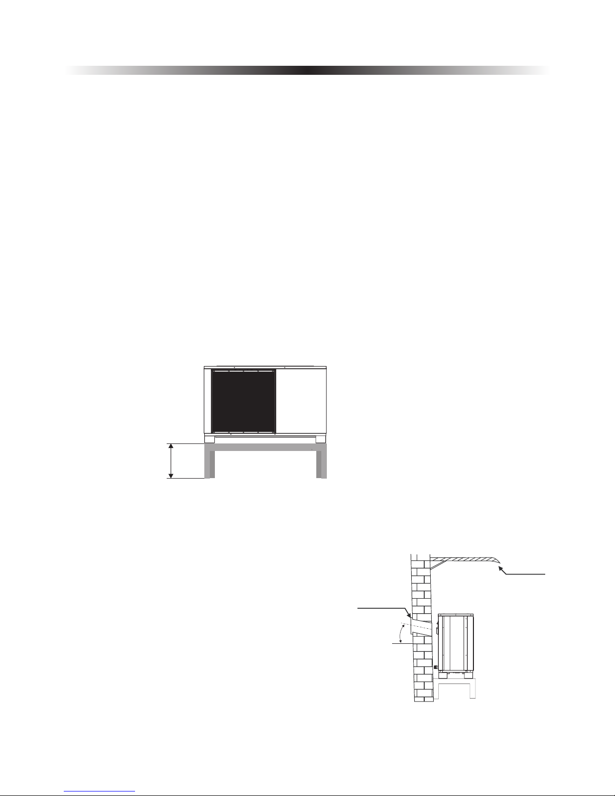
5) When installing the unit in harsh climatic conditions, sub-zero temperatures, snow, humidity..., please
raise the unit above the ground by about 50cm.
6) Please ensure there is drainage system around the location, to drain the condensate water under
defrosting mode.
7) When installing the unit, tilt it by lcm/m for rain water evacuation.
8)
9) Please don't install the indoor control unit and unit in damp locations, otherwise it may
cause short-circuit or corrosion of some components. The unit should be free from corrosive and
moisture surrounding. Otherwise the lifetime of the unit might be shortened.
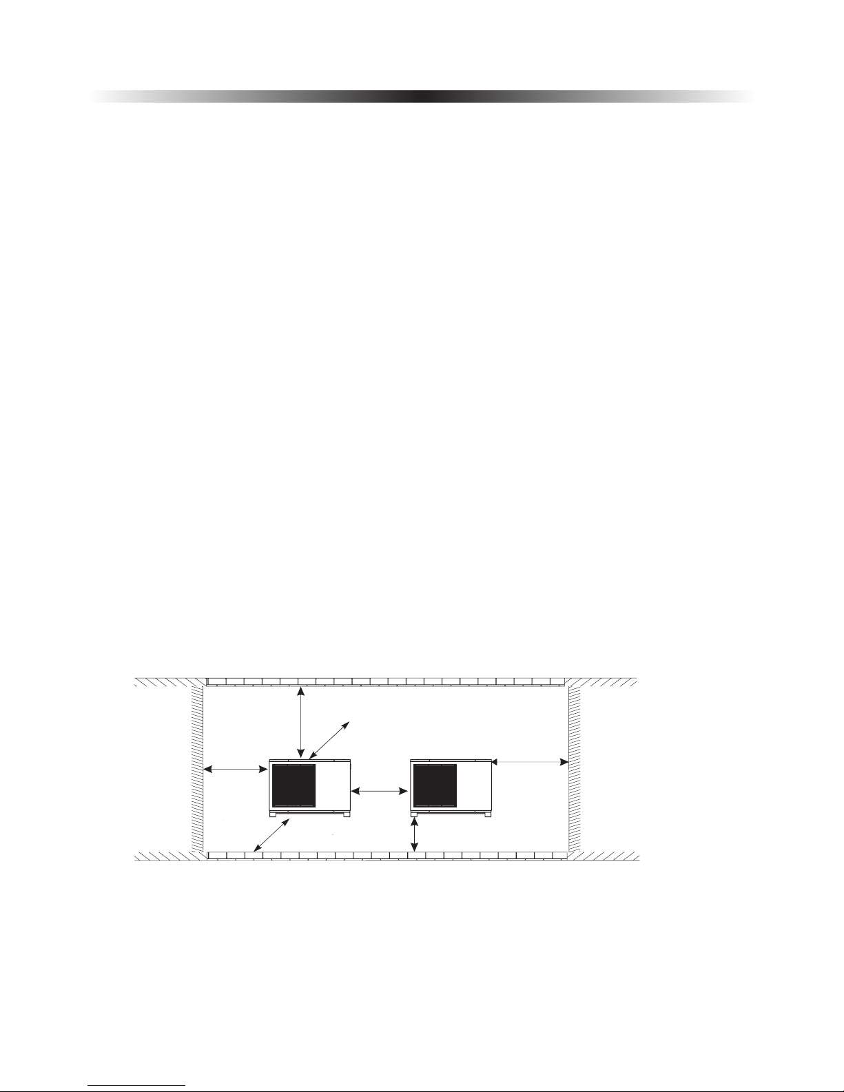
10) Please ensure enough space around the unit, for better ventilation and maintenance.
Please refer to the illustration below.
monoblock monoblock
Monoblock
monoblock
monoblock
monoblock
monoblock
monoblock
monoblock
If the unit is
installed in humid environment, electronic components may get corroded, or short-circuited because of
heavy humidity.
It's recommended to install an awning above the unit, to protect the snow from clogging in
the air inlet and outlet and ensure the normal running.
Install unit far away from the exhaust port of kitchen, to avoid oil smoke entering
into unit and adhering to heat exchanger. It's hard to clean up.
2. Installation
15
≥650mm
≥400mm
≥150mm( )Back space
≥1500mm
()Front
space
≥500mm
≥500mm
≥500mm
( )Above ground
2. Installation
2.4.2 Installation
User can either use the dedicated mounting bracket from the supplier, or prepare a suitable bracket for the
unit installation. Make sure the installation meets following requirements:
1) The unit must be installed on flat concrete blocks, or a dedicated mounting bracket. The bracket should
be able to support at least 5 times of unit’s weight.
2) All nuts must be tightened after the bracket is fixed; otherwise, it may cause damage to the equipment.
3) User should double check and make sure the installation of unit is firm enough.
4) The bracket can be of stainless steel, galvanized steel, aluminum and other materials as required by the
user.
5) Besides the mounting bracket, the user can also install the monoblock unit on two concrete blocks, or a
raised concrete platform. Please make sure that the unit is securely fastened after installation.
6) Please see the dimensions of unit when choose a suitable wall bracket. monoblock
≥500mm
◆ Hole for piping kits should lean to outside a little bit
(≥8 degrees), to keep rain water or condensate water
from flowing back indoors.
≥8°
Sleeve
Shield
16
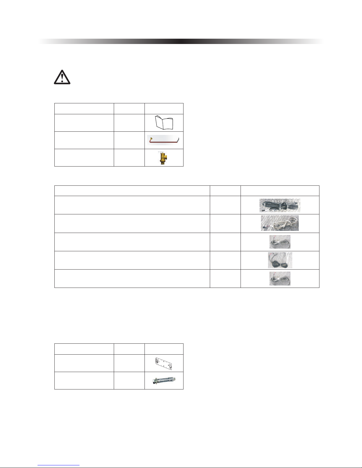
2.5 Accessories
Accessories below are delivered together with the product .
Please check in time. If there is any shortage or damage, please contact local distributor.
Name
Quantity
Picture
User’s manual
Drain pipe
1
Safety valve kit
1
1
User Ma nual
2. Installation
Indoor control unit
bracket
1
Expansion bolts
2
Name
Quantity
Picture
17
Name
Quantity
Picture
1
1
TR-Room temperature sensor
TC-water temperature sensor for cooling
TH-water temperature sensor for heating
1
Communication cable between indoor control unit and
monoblock unit
Communication cable
Signal cable between indoor control unit and monoblock
unit
1
1
TW-Water temperature sensor for hot water
◆
◆
◆
◆
◆
◆
◆
◆
◆
It is recommended to use a suitable circuit breaker for the heat pump;
The power supply to the heat pump unit must be grounded.
The wiring should be done by professional person.
The wiring should be comply with the local industry regulation.
The wiring should be done after the unit is powered off.
Cable should be fixed tightly, to ensure it won’t get loose.
Don't connect several parts of cables together to use.
Make sure the power supply in the local coincide with the power supply marked in rating label.
Make sure power supply, cable and socket can meet the requirement of the input power of the unit.
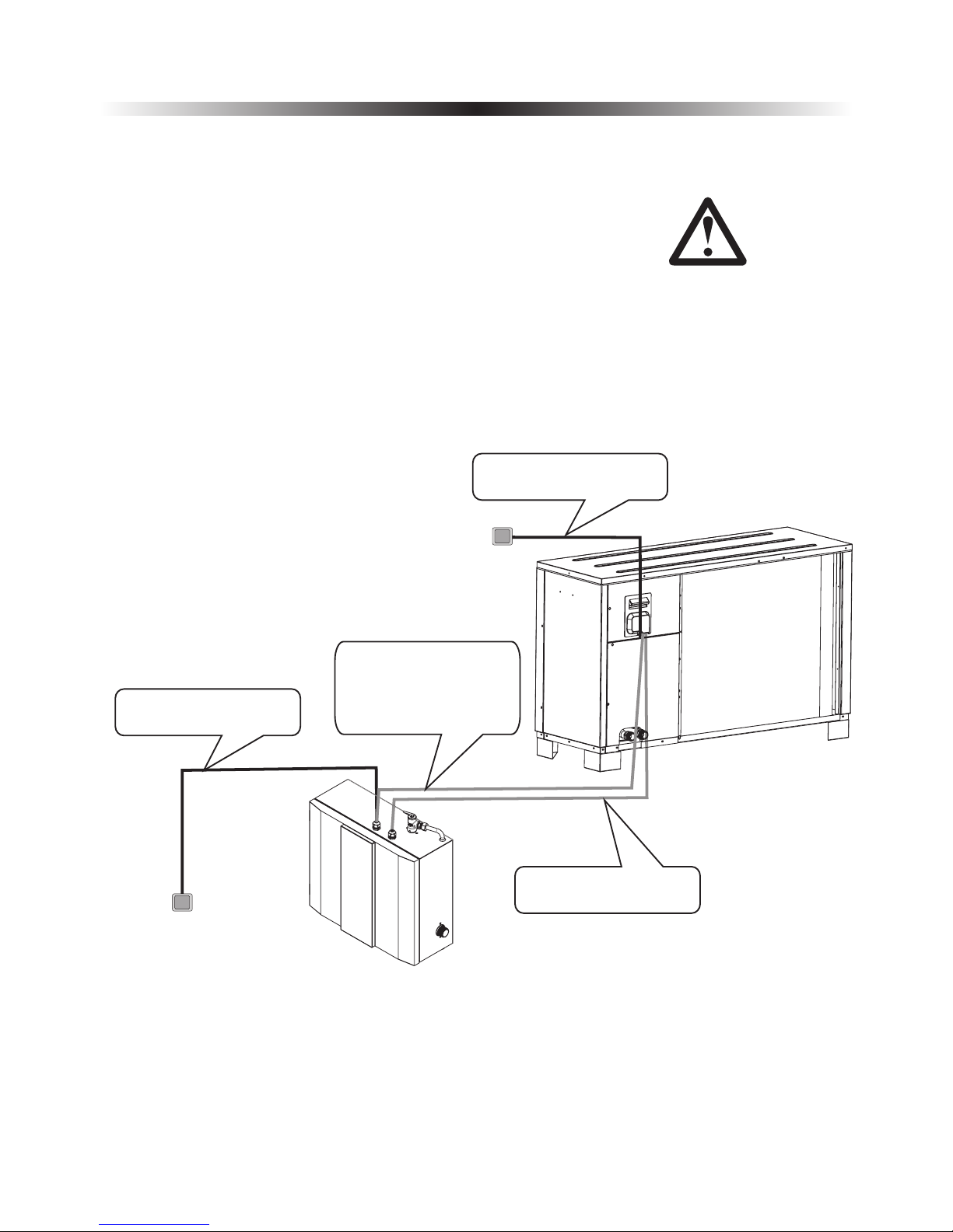
2.6 Wiring
2. Installation
Installation sketch
18
Signal cable between
indoor and outdoor unit
Main power
in user side
Heat pump unit power
supply
Aluminum foil electric
heating piece power cable
between indoor control
unit and monoblock unit
Heat pump monoblock unit
power supply
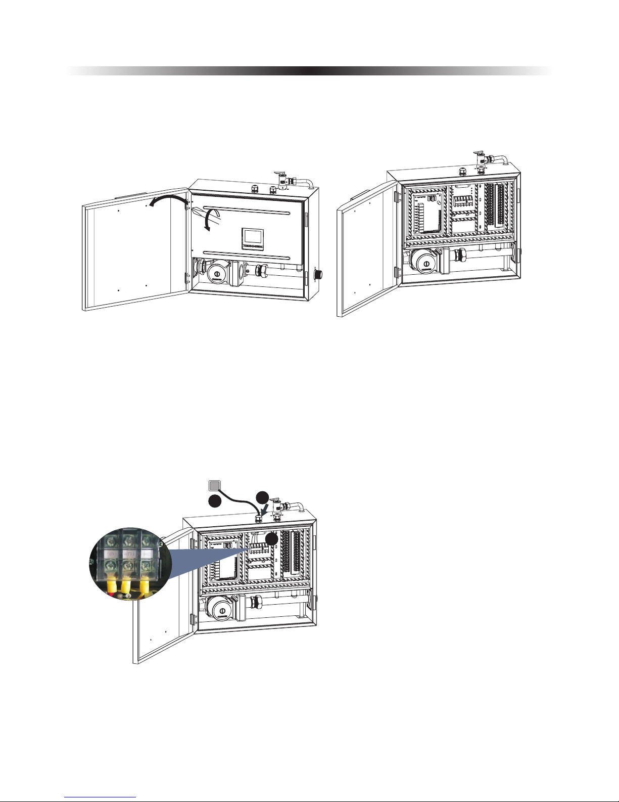
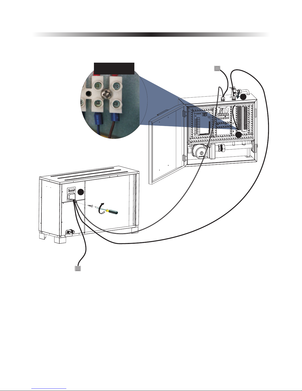
1) Heat pump unit power supply
Get a power cable in suitable length that complies to the local safety regulations.
Before wiring, open the indoor control unit front panel and take off the electronic box cover.
A. Insert one end of this cable through the
cable gland on bottom of the indoor control
unit, and connect it with heat pump power
supply terminals (G, N, L).
B. Fasten the cable gland to ensure the cable
won't get loosen.
C. Connect the other end to the city power
supply.
2. Installation
19
A
B
C
G N
L
2. Installation
20
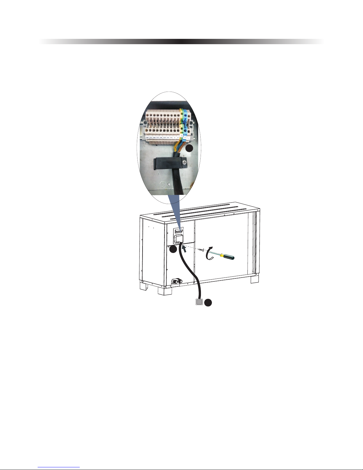
2) Monoblock unit power supply.
C
B
A
Get a power cable in suitable length that complies to the local safety regulations.
A. Insert one end of this cable through the cable gland on back of the outdoor control unit,
and connect it with heat pump power supply terminals (G, N, L).
B. Fasten the cable gland to ensure the cable won't get loosen.
C. Connect the other end to the city power supply.
2. Installation
21
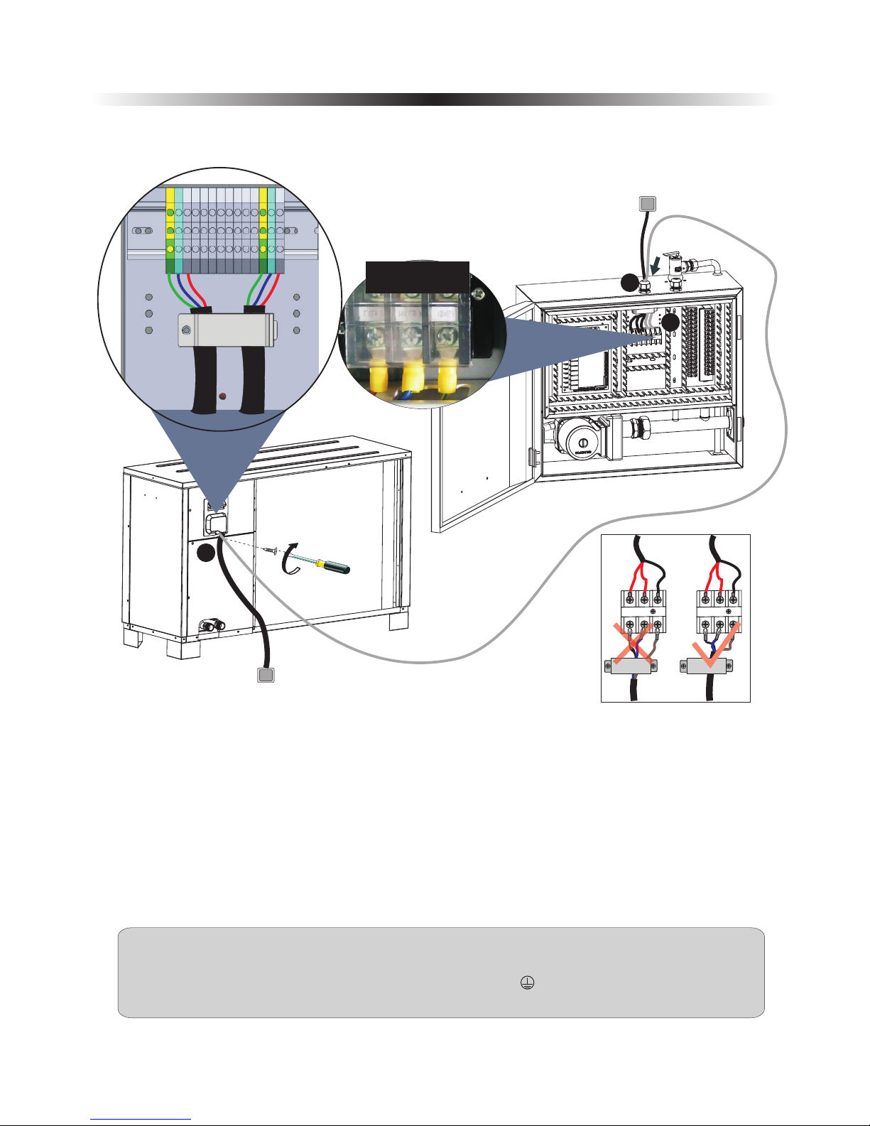
When connecting the power cable between the monoblock unit and indoor control unit, cables
connected to the terminal block in indoor control unit must match these in monoblock unit.
For example, if the terminals and power cables are connected as →gree/yellow cable, L→red cable,
N→blue cable, the connections in the monoblock unit should be in the same way.
3) Aluminum foil electric heating piece power cable between indoor control unit and monoblock unit
Prepare a 3 cores power cable with suitable length that complies the local safety regulations,
A. Insert one end of this cable through the cable gland on top of the indoor control unit, and connect
this power cable to "Outdoor unit” on indoor control unit terminal block.
B. Fasten the cable gland to ensure the cable won't get loosen.
Connect cable between indoor control unit and monoblock unit to correspondent terminal block
according to the wiring diagram. Fasten the cable gland to ensure the cable won't get loosen.
C.
C
B
Sho wn as "Ou tdoor u nit
" on wi ring di agram
G
HN
HL
For more solid connection, for that cables that need to be connected with terminals:.
1.Please try to use solid ware instead of strand wire.
2.If stranded wire is used, please make a pin terminal on the end.
3.The stripped length of the wire should be no shorter than 10mm.
A
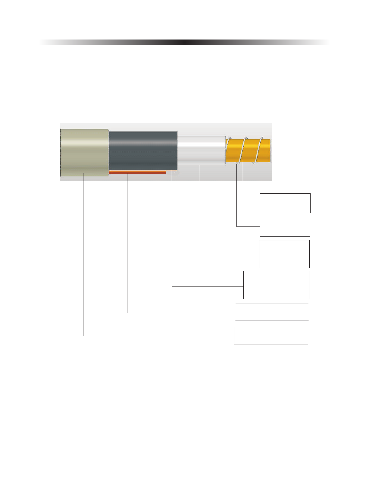
Warning.
Electric heater for water lines inside outdoor cabinet must be attached. Pipe insulation must be able
to hold 120℃. Separate power supply to heater.
Water pipe connected between monoblock unit and house (water pipe in between should not longer
than 50cm.)
2. Installation
22
Copper or Steel
water pipe,28mm
Electric heating
cable.
Aluminum foil,
reflex heat back
to water pipe.
Insulation, that
can hold temperature
over 120℃
Power and signal cables
Wrapping material.
2. Installation
23
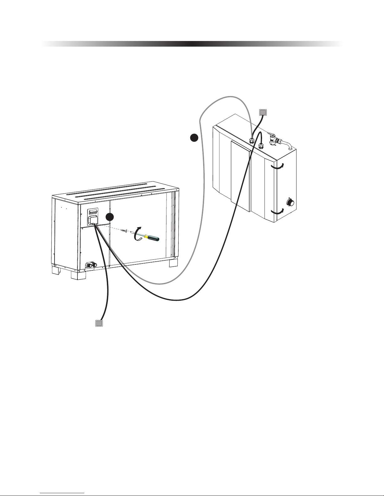
4) Signal cable between indoor control unit and monoblock unit
10M communication cable is packed in accessories bag.
A. Insert one end of this cable through the cable gland on top of the indoor control unit, and connect
this cable to A, B, on terminal block.
B. Fasten the cable gland to ensure the cable won't get loosen.
Take off the electric box cover, and connect the other end of communication cable to correspondent
terminal block through cable gland. Fix the cable with cable gland after cable is well connected. A, B,
on monoblock unit should be connected with A, B on indoor control unit, otherwise unit will show
communication failure.
C.
C
B
A
B
corresponding
with each other
A
2. Installation
24
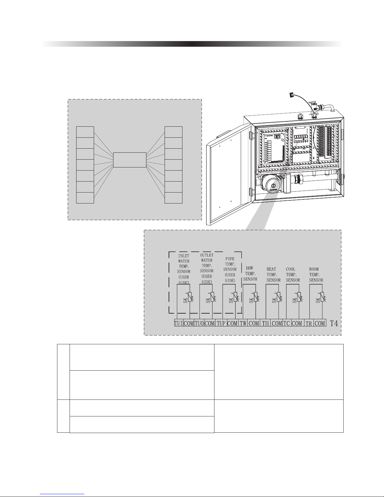
5) Sensor cables
Take all sensors and communication cables out from the accessories bag. Connect the sensors together with
the quick connectors on communication cables. After done, insert communication cables (the end without
quick connector) that have no quick connector through cable gland, and connect them to the correspondent
terminals on terminal block.
A
TR-Room temperature sensor
B
TUP-Coil temperature sensor
TUI-Water inlet temperature sensor
Connect these sensors with communication
cables by quick connector, and then connect
communication cable (the end without quick
connector) with terminal block. (These
sensors are packed inside the accessories
bag).
TUP/TUI/TUO(terminal of indoor PCB
and outdoor sensor) are connected to the
terminal board, connect via cushion cable.
Place all sensors in right positions
Sensor cable connection
Indoor control
Communication cable
CO M
TU I
CO M
TU O
CO M
TU P
CO M
CO M
TU I
CO M
TU O
CO M
TU P
CO M
TC-water temperature sensor for cooling
TH-water temperature sensor for heating
TW-Water temperature sensor for hot water
2. Installation
Install the electric box cover on indoor control unit and electric box cover on monoblock unit
back, and close the door of indoor control unit.
25
C
C
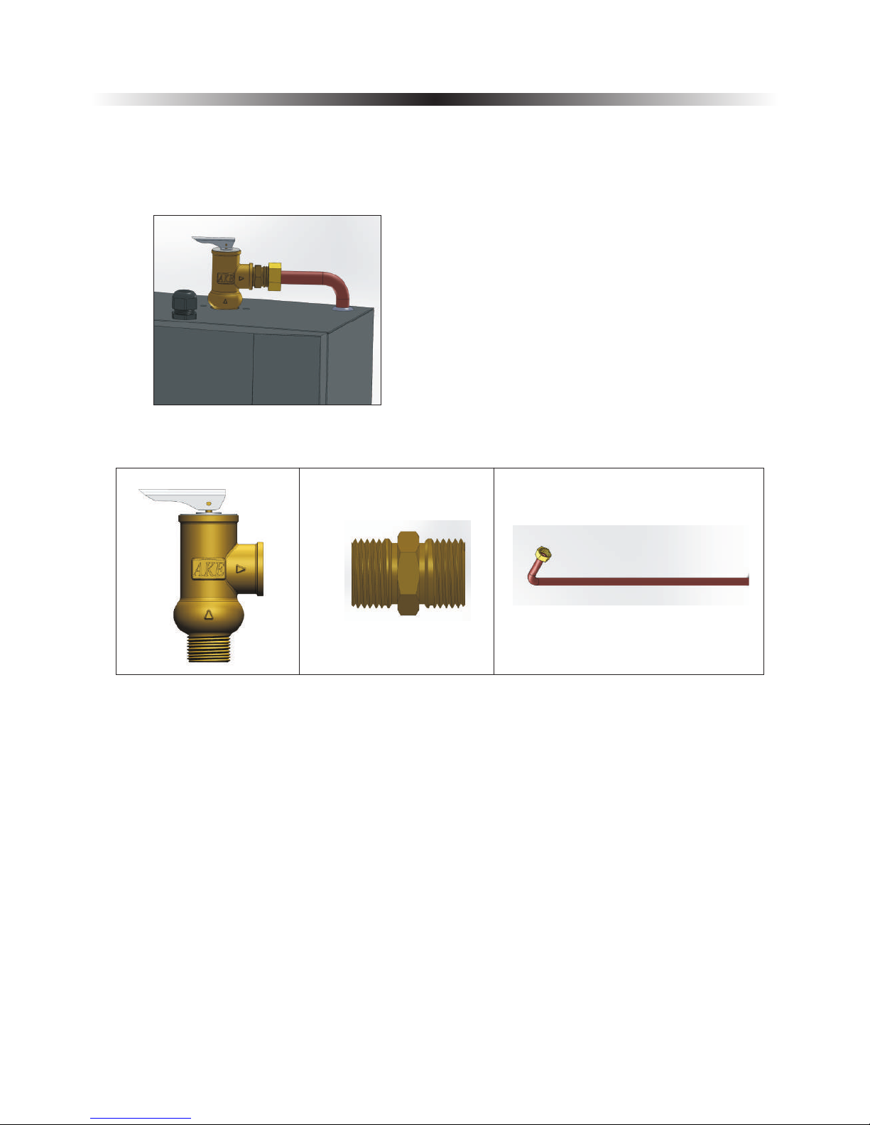
2.7 Installation of safety valve kit
1) Install the safety valve kit to the connector on top of indoor control unit.
2) Connect the drainage pipe to safety valve outlet.
2. Installation
26

2.8 Water pipe connection
After installing the unit, please connect the water inlet and outlet pipe according to the local .
Please carefully select and operate the water pipe.
After connection, the water piping should be pressure tested, cleaned before use.
1) Filter
A mesh filter must be installed in front of the water inlet of the unit and water tank, to keep the water
quality and collect impurity contained in the water. Take care to keep the water filter mesh towards the
bottom. Check valve is recommended to be installed at both sides of the filter, so as to clean or change the
filter in a easier way.
regulations
2) Insulation
All pipes running hot water should be well insulated. The insulation
must be tied up tightly without gap (But please don't wrap up the
check valve for future maintenance).
3) Requirements of water quality
A. Chloridion element in the water should be less than 300ppm(temperature is less than 60℃).
B. PH value of water should be from 6 to 8.
C. The water with ammonia can't be used for the unit.
If the water quality is bad, or water flow too little, scale formation or clogging may happen after unit
running for a long time, then the efficiency of cooling or heating will be low or the unit will work
abnormally.
Please clean water before use, or use purified water. Make sure the water quality is good enough to keep the
unit long-term running in high efficiency.
One way valve
Drain pipe
Filter
Ball valve
City water inlet
Connect to unit
water inlet
Please ensure enough water pressure to send the water to the required height.
If the water pressure is not enough to maintain proper water flow rate for the system,
please add a water pump to increase the pumping head.
2. Installation
27

1)
Before the unit starts up, a certain number of verifications must be performed on the installation to ensure
that the unit will operate under the best possible conditions. The check list below is not exhaustive and
should only be used as a minimum reference basis:
A. Make sure fan rotates freely;
B. Inspect all water piping for flow direction;
C. Verify all system piping is correct for operation as per installation requirements;
D. Check voltage of the unit power supply and make certain voltage is within authorized limitations;
E. Make sure the unit is properly grounded;
F. Check the presence of protective and breaking devices;
G. Check all electric connections for tightness.
H. Check all piping for leaks and air is well ventilated.
Before start-up
2) Pre-start up
A. When the installation of unit is completed, water system pipes are well connected and air purging is
done, no leakage or other problems, the unit can be powered to start up.
B. Turn on the unit, press the on-off button on the operation panel to start the unit. Please check carefully
if there is some abnormal noise or vibration, or the display of wired controller is normal or not.
C. After the unit is working properly for 10 minutes, without any problem, then the pre-start up is
completed; If not, please refer to the Service and Maintenance chapter in this manual to solve the
problems.
If everything above is OK, the unit can start up.
If any of them fails, please fix it.
It is suggested not to run "heating" or "hot water" mode, when ambient temperature is
over 32 ℃,otherwise unit may go into protection mode easily.
2.9 Test run
After installation finished, please fulfill the water system with water and purge out air
in the system before start-up.
2. Installation
28

3. Usage
29
3.1 Introduction of wired controller
1
2
ON/OFF
MODE
Up-Regulation
Timer
Confirm
Down-Regulation
Symbol
Function
Explanation
Heating mode
Cooling mode
Shower
Water mode
Heat recovery
function
Actual set
temperature
Actual water
temperature
Quiet operation
Defrosting
Degrees in Celsius
of Fahreneit
Operation values
Auxillary heater
step 1 and step 2
Anti legionella
function
Working mode
When heating mode is selected, symbol is
shown in the display
When cooling mode is selected, symbol is
shown in the display
When shower water mode is selected,
symbol is shown in the display
When auxillary heater is connected and
activated, symbol is shown in the display
Increases the shower water temperature wirth
electric heater weekly to kill bacterias
Shows the actual water temperatdure in
according to units operation mode
Shows the actual set temperatdure in
according to units operation mode
Not available for this model
Lower the working speed of compressor
and fan motors in selected time periode
Deicing the outdoor unit evaporator when ice
is build up. (Self learning, not adjustable)
Shown when digits is correspondent with
temperatures
Shows selected temperature values when unit
is on or parameter setting values
Symbol display when selected,
flickers when activated
shown in
Symbol display when selected,
flickers when activated
shown in
Symbol display when selected,
flickers when activated
shown in
Symbol flickers when step 1,
2 or both are "ON"
Symbol starts flickering when function
is "ON"
Always "ON" when unit is "Water Control"
Always "OFF" when unit is "Room Control"
Always "ON" when unit is "ON"
When activated this symbol is "ON"
When defrosting is activated this sumbol is
"ON". For dual compressor system: left
symbol = system 2, right symol = system 1.
When parameter setting is selected, values
are shown in accordance to the parameter
setting menu
Anti feezing
protection
Self function to avoid freezing
when ambient temperature drops and unit is
in "OFF" mode. (Not adjustable)
protection
Constantly lights for primary anti-freezing
protection.
Flickers for secondary anti-freezing
protection.

3. Usage
30
Symbol
Function
Explanation
Compressor
indicator
Clock or parameter
indicator
Timer
Down value
Set button/Clock
UP value
Operation mode
selector
Timer button
Timer Shower
water
Timer
heating/cooling
ON/OFF
Working mode
1
2
Indicates the current working level,
“low range30-46”, "middle range47-65",
"high range66-100”
If symbol is "ON" compressor is working
Clock and parameter menu and group
indicator
Shows time when unit is "ON", Shows
parameter groupe or -number when unit
is "OFF" and parameter setting is selscted
Indicates that one or more operation timer
parameters is selected
When "ON" means unit is "OFF" until the
selected time where unit is set to be "ON"
Indicates that shower water is set to "Timer"
operation, and weather it is in "ON" periode
and if unit actually is working in this mode.
“1" shows that "Timer" for shower water
mode is selscted and that unit is within its
"ON" periode. "ON" indicates that unit is
actually working in shower water mode
Indicates that heating/cooling mode is set to
"Timer" operation, and weather it is in "ON"
periode and if unit actually is working in this
mode.
"2"shows that "Timer" for heating/
cooling mode is selscted and that unit is
within its "ON" periode. "OFF" indicates
that unit is not working in heating/cooling
mode at the moment
Button switch the entire unit on and off
Button a so have some parameter setting
functions
l
Button switch between basic operation
modes, Heating/cooling/shower/water, and
different combinations of these
Button have some parameter setting
functions
also
Button increases set temperature, switch
between parameters or adjust set value in
parameter setting menu
Button have some parameter setting
functions
also
Button deacreases set temperature, switch
between parameters or adjust set value in
parameter setting menu
Button have some parameter setting
functions
also
Button activates the unit for changing in set
values in temperatures or parameters and
button enters clock setting when the unit “OFF”
Button have some parameter setting
functions
also
timer settings
Button have some parameter setting
functions
also

3. Usage
31
3.2 Parameter Setting Overview
Item
Item
Sub-menu
Sub-menu
Unit Statue
Under
Unit Statue
Operation
Level
Operation
Level
Default factory
settings
Default factory
settings
Clock Time
Temp. Setting
Working Mode
Room Temp.
Control
None
Hot water/Heating/Cooling
Hot water, heating, cooling, hot
water+heating, hot water+cooling,
heating+cooling, hot water+heating
+cooling
OFF
ON
ON
ON
User
User
User
User
No matter the unit is ON or OFF, press button to check or actiave "Timer" parameter setting. Use or
button to view all parameters in sequence. When the value of a parameter needs to be adjusted, press "SET" when
this parameter is shown to activate the setting of this parameter. The value start flickering.
Use button to adjust the value, or button to adjust setting in "hours", button to adjust the setting in
“minutes", if this parameter is a time parameter.
Timer function ON/OFF
0 (OFF)
Hot Water Timer ON-1
00:00
Hot Water Timer OFF-1
00:00
Hot Water Timer ON-2
00:00
Hot Water Timer OFF-2
00:00
Heating/Cooling Timer ON-1
00:00
Heating/Cooling Timer OFF-1
00:00
Heating/Cooling Timer ON-2
00:00
Heating/Cooling Timer OFF-2
00:00
Normal Shower Time (for unit with
heat recovery function only)
00:00
Anti-legionella function
00:00
Anti-legionella function starting
time
00:00
Pump anti-block running time
00:00
Quiet operation starting time
00:00
Quiet operation ending time
00:00
ON/OFF
Timer
Parameter
User
00:00
20°
Page in
the menu
Page in
the menu
36
38
36
37
39
39
40
40~41
41

3. Usage
32
All the units sensor values (temperatures) and information of current running statue (compressor speed, voltage
and current) can be red and checked via operation panel in both ON/OFF statue. Press and buttons for 5
seconds in main interface, to activate the menu of current running statue. Press or buttons to check all working
status in sequence in accordance to below list. The current number is displayed where the clock is displayed in main
interface. See operation panel symbols in page...
Item
Meaning
1
19
2
20
3
21
4
22
5
23
6
24
7
25
8
26
9
27
10
28
11
29
12
30
13
31
14
32
15
33
Item
Meaning
User level Parameter under basic operation level can be set in "OFF" mode only. Press "SET"+"M" for 5 seconds,
Parameter will shown on the display. Press or to check parameter values for each paramter in sequence.
Item
Sub-menu
Unit Statue
Operation
Level
Default factory
settings
Hot Water restart based on water ∆T
Heating restarts based on water ∆T
Cooling restarts based on water ∆T
Cooling and heating switch judgment
User level
Parameter
Check in
ON/OFF, Set
in OFF
User
5
°
2°
2°
0 (OFF)
Page in
the menu
44
44
DHW Set Temp
16
34
17
35
18
36
Heating Set Temp
Cooling Set Temp
Room Set Temp
Ambient temperature
Hot water temperature
Heating water temperature
Cooling water temperature
Room temperature
Unit outlet temperature
Unit inlet temperature
System 2
temperature
indoor coil
System 2 voltage (V)
System 2 current (A)
System 2
(Hz)
compressor speed
System 2 comp.
discharge temp.
System 2
temperature
outdoor coil
System 2 suction temperature
System 2 evaporating pressure
System 2 condensing pressure
System 2 EEV position
System 1 indoor coil temperature
System 1 voltage (V)
System 1 current (A)
System 1 compressor speed (Hz)
System 1 outdoor coil temperature
System 1 comp. discharge temp.
System 1 suction temperature
System 1 evaporating pressure
System 1 condensing pressure
System 1 EEV position
Indoor Unit Software Version
System
Versio n
2 Outdoor Unit Software
System
Versio n
1 Outdoor Unit Software
Water outlet Temp.
Too Low Protection
Water outlet Temp.
Too High Protection

3. Usage
33
Item
Sub-menu
Unit Statue
Operation
Level
Default factory
settings
Ambient temp. to start heating
20
Ambient temp. to start cooling
25°
°
Shifting priority
100
°
Set room temperature
20°
Check in
ON/OFF, Set
in OFF
User
Temperature
Parameter
1.Code input: When unit is in "OFF" mode, press for 5 seconds, "----" will be shown. Press to swfit
between 4 positions, and press to adjust the value of the blinking value. Press "SET" to confirm the input
password. If the password is correct, "Advanced Setting" mode is activated.
2.Complete Advanced Setting menu is divided into 6 groups (Group 0~Group E). When Advanced Setting menu
is activated, press to switch between each group(Group 0, A, B, C, D,E) .
3.Press or to switch different parameters in the same group. Press "SET" to activate setting of current
parameter, with its value blinks, and adjust its value by or . Press "SET" to confirm the setting.
Item
Sub-menu
Unit Statue
Operation
Level
Default factory
settings
Advanced
Setting Group
0
Test working mode indoor controller
External ON/OFF switch
Water flow switch
Heating buffer tank
Cooling buffer tank
Priority switch between hot water
and heating operation
Refrigerant collecting function
Lock Function
Installer
OFF
0 (Normal
operation)
0 (Invalid)
60 sec
0 (No)
0 (No)
0 (hot water)
0 (OFF)
00 (OFF)
Advanced
Setting Group
A
Unit Circulation Pump Control
Type
Heating Circulation Pump Control
Type
Cooling Circulation Pump Control
Type
Heating Circulation Pump Start
Temperature
Heating Cirulation Pump Stop
Temperature
Cooling Circulation Pump Start
Temperature
Cooling Cirulation Pump Stop
Temperature
Installer
OFF
0 (unit controlled)
0 (unit controlled)
0 (unit controlled)
20
°
18°
18
°
20
°
Page in
the menu
Page in
the menu
44
44
49~50
51
53
53
Available working modes
2(all func tions)
Stop/Speed down ΔT based on
set temperature in heating/cooling
2℃
30 min
Max Allowed Duration For Min
Compress or Speed
46~47
52

3. Usage
34
Item
Sub-menu
Unit Statue
Operation
Level
Default factory
settings
Advanced
Setting Group
Advanced
Setting Group
Installer
Installer
OFF
OFF
Advanced
Setting Group
Advanced
Setting Group
A
D
Unit Motorized 3-way valve
Switching Time
Heating Operation Motorized
3-way valve Direction
Installer
Installer
OFF
OFF
1 same as cooling
operation
120 sec
B
C
Anti-Legionella Set Temperature
Anti-Legionella Duration
Anti-Legionella Maximum
Allowable Working Duration
Anti-freezing Function
Anti-freezing Starting Ambient
Temperature--Primary
Anti-freezing Starting Ambient
Temperature--Secondary
Anti-freezing Ending Ambient
Temperature--Secondary
Anti-freezing Starting Water
Temperature--Secondary
Anti-freezing Ending Water
Temperature--Secondary
60
120 min.
1 (ON)
5°
2°
5°
2°
15°
Manual ON/OFF of Heater in Hot
Water Mode
Backup Heating Source For Hot
Water Mode
Priority Of Backup Heating Sources
For Hot Water Mode (Compared
With Unit Auxiliary
Heater)
Temperature Increasement
Checking Duration in Hot Water
Mode
Maximum Allowable Set Water
Temperature in Heating Mode
Manual ON/OFF of Heater in
Heating Mode
Backup Heating Source For Heating
Mode
Priority Of Backup Heating Sources
For Heating Mode (Compared With
Unit Auxiliary
Heater)
Accumulated Value between
operation time VS set temp.
for Heating Mode
0 (OFF)
0 (No)
0 (lower)
40
42
0 (OFF)
1 (Yes)
1 (Higher)
45
Heating Curve Function
Room Temp. Effect On Heating
Curve
1 (ON)
0 (OFF)
Page in
the menu
54
54
55
56
57
46
46
30 min.

3. Usage
35
Item
Sub-menu
Unit Statue
Under
Operation
Level
Default factory
settings
Advanced
Setting Group
Advanced
Setting Group
Installer
Installer
OFF
OFF
D
E
Ambient Temp. 1
Ambienttemp 1 Vs Water Temp. 1
Ambient Temp. 2
Ambienttemp 2 Vs Water Temp. 2
Ambient Temp. 3
Ambienttemp 3 Vs Water Temp. 3
Ambient Temp. 4
Ambienttemp 4 Vs Water Temp. 4
Ambient Temp. 5
Ambienttemp 5 Vs Water Temp. 5
12
25
7
28
2
31
-7
35
-20
42
Heat Recovery Function
Hot Water Restart Based On ∆T in
Heat Recovery Operation
Hot Water Stop Based On ∆T in
Heat Recovery Operation
Allowable Temp Drift In Heating
in Shifting Priority Operation
Hot Water Min. Working Hours in
Shifting Priority Operation
Heating Max. Working Hours in
Shifting Priority Operation
Working of Extra Heating Source
for Hot Water in Shifting Priority
Operation
0 (Invalid)
5
°
5
°
5
30
50
0 (No)
Page in
the menu
46
57~58
58

3. Usage
36
3.3 Basic Operation
When the unit is O FF, press to tu rn on t he un it. The un it wi ll wo rk in its last working mode.
Press again to t urn o ff the un it.
Press for 5 seco nds
Value flickers
Press to adjus t
time by hours
Press to adjus t tim e
by minutes.
When the unit is i n OFF m ode , press "SET" for 5 seconds, to activate clo ck ti me se tting, with the
value flicke rs. P res s to adjust time by hours; press to adjust time b y min ute s.
Chose workin g mod e set tings in accordance to your heating/hot w ate r/c ooling system.
When the unit is O N, pr ess " M" to s et the unit working mode. For each time “M” is p res sed w ork ing mode
is changed by th e bel ow se quence. When a working mode is selected, it s sym bol (s) will be shown on the
screen. The cu rre nt wo rking mode of the unit, is shown by a flickerin g wor kin g mode symbol.
Picture show s tha t
heating and ho t wat er
mode is select ed
Worki ng Mo des
Hot water+He ati ng
Symbols
Hot water
Hot water+Co oli ng
Heating only
Auto
Cooling only
Hot water+Au to
OFF: The unit is
OFF when it is
fed with power.
【 】
ON/OFF
【 】
Clock time setting
【 】
Woking modes setting

3. Usage
37
When unit is ON, k eep o n pre ssing "M" to switch the control of cooling an d hea tin g operation between room
temperatur e con tro l and water temperature control mode .
When in water te mpe rat ure control mode, "Water Temp." will be shown on the screen;
When in room tem per atu re control mode, "Water Temp." will not be shown on the screen .
Note:
If unit is set to Ho t Water mode only, or unit is set to c omb ine d wor kin g mode but unit is working in hot
water mode, this operation is i nva lid .
Room tempera tur e
control mode
Wate r tem per ature
control mode
Single worki ng mo de
Keep on
pressing "M”
When unit is on and working mode is selected, press “set”
to activate the temperature setting. Working mode symbol
flickers.
Adjust the set temperature by:
Press to increase the set temperature by 1℃.
Press to decrease the set temperature by 1℃.
Note:1. If heating curve function is activated, set temperature for heating will be calculated according to the set
curve automatically. Its set temperature can't be adjusted by this operation.
2. If room temperature control mode is activated, temperature set here for heating and cooling
is based on room temperature.
【 】
Room Temperature Control
【 】
Temperature setting
Combined working mode
When combined working mode is selected, unit will switch between selected working modes. For example heating + hot
water, unit will switch between space heating and hot water operation. Press “set” to activate the temperature
settings. The working mode symbol that is being adjusted, flickers. Adjust the temperature setting by using the
/ arrows.
Press “set” to confirm the setting, and activate following
working modes temperature setting, with its working mode
symbol flickers. Adjust the temperature setting by using the
/ arrows.
Press "SET" to switch the temperature setting between selected working modes in sequence.

3. Usage
38
Timer function allows you to control different working modes at spesific hours during a 24 hour periode, for even more
energy savings. For example you can turn off hot water production in the daily hours you don’t use this. In the selected
periode unit will not produce hot water even hot water is selcted as working mode in your application. The setting is
repeted every 24 hours until it is disactivated.
Parameter list
0
1
2
3
4
5
6
7
8
9
10
11
12
13
14
Parameter No.
Meaning
Range
Default Value
0
0
00 00
00 00
00 00
00 00
00 00
00 00
00 00
00 00
00 00
00 00
00 00
00 00
00 00
0(off), 1(on)
0(off), 1(on)
00 00-23 59
00 00-23 59
00 00-23 59
00 00-23 59
00 00-23 59
00 00-23 59
00 00-23 59
00 00-23 59
00 00-23 59
00 00-23 59
00 00-23 59
00 00-23 59
00 00-23 59
Timer function ON/OFF
Hot Water Timer ON-1
Hot Water Timer OFF-1
Hot Water Timer ON-2
Hot Water Timer OFF-2
Heating/Cooling Timer ON-1
Heating/Cooling Timer OFF-1
Heating/Cooling Timer ON-2
Heating/Cooling Timer OFF-2
Normal Shower Time (for unit with
heat recovery function only)
Anti-legionella function
Anti-legionella function starting time
Pump anti-block running time
Quiet operation starting time
Quiet operation ending time
No matter the unit is ON or OFF, press to check or actiave "Timer" parameter setting, which looks as shown below:
Value of parameter
Number of parameter
Parameter 00, value=0000
Use or to view all parameters in sequence. When the value of a parameter needs to be adjusted, press "SET"
when this parameter is shown to activate the setting of this parameter. The value start flickering.
Use to adjust setting in hours, to adjust the setting in minutes" if this parameter is a time parameter
【 】
Time&Timer Setting

3. Usage
39
For example, parameter 00 is to set the ON/OFF of complete timer function (if it is set
to OFF, following parameters 01~08 will be invalid). When setting for this parameter is
activated, use to adjust the value.
For example, parameter 01 is the ON time for hot water function. When setting for
this parameter is activated, press to adjust the setting in hours; press to
adjust the setting in minutes" for parameter that relates to time
Timer setting parameter 0 to 8.
To be able to activate timer setting for parameter 1 to 7, parameter 0 needs to be activated first.
0
Parameter No.
Meaning
Range
Default Value
0
0(off), 1(on)
Timer function ON/OFF
Meaning of each parameter
Hot Water Timer:
1
1
2
2
3
3
4
4
Parameter No.
Parameter No.
Meaning
Meaning
Range
Default Value
Value
00 00
04 00
00 00
09 00
00 00
14 00
00 00
21 00
00 00-23 59
00 00-23 59
00 00-23 59
00 00-23 59
Hot Water Timer ON-1
Hot Water Timer ON-1
Hot Water Timer OFF-1
Hot Water Timer OFF-1
Hot Water Timer ON-2
Hot Water Timer ON-2
Hot Water Timer OFF-2
Hot Water Timer OFF-2
For example, if the below setting is set; domestic hot water will only be heated up during the period 04:00~09:00, and
14:00~21:00 every day.
These parameters are used for setting the ON/OFF timer for hot water operation. After setting, unit will only activate hot
water operation in the selected period(s).
For how to make the setting, please refer to previous page.

3. Usage
40
5
5
6
6
7
7
8
8
Parameter No.
Parameter No.
Meaning
Meaning
Range
Default Value
Value
00 00
00 00
00 00
08 00
00 00
17 00
00 00
23 59
00 00-23 59
00 00-23 59
00 00-23 59
00 00-23 59
Heating/Cooling Timer ON-1
Heating/Cooling Timer ON-1
Heating/Cooling Timer OFF-1
Heating/Cooling Timer OFF-1
Heating/Cooling Timer ON-2
Heating/Cooling Timer ON-2
Heating/Cooling Timer OFF-2
Heating/Cooling Timer OFF-2
Then heat pump will only heat or cool the house during the period 00:00~08:00, and 17:00~23:59 every day.
1
2
When timer function is activated, following symbols might be shown on the screen:
This symbol means the unit
is in sanitary hot water Timer
ON period. Unit will work in
hot water mode when needed.
This symbol means the unit is
in cooling/heating Timer ON
period. Unit will work in
cooling/heating mode when
needed.
1
This symbol means the unit is
in sanitary hot water and
cooling/heating Timer ON
period. Unit will work for both
hot water and cooling/heating
mode (not in same time) when
needed.
This symbol means the unit is
neither in hot water nor
cooling/heating Timer ON period.
Unit will work not work for both
hot water and cooling/heating
mode even needed.
Normal Shower Time:
Parameter No.
Meaning
Range
Default Value
9
00 00
00 00-23 59
Normal Shower Time (for unit with
heat recovery function only)
Heating/Cooling Timer:
These parameters are used for setting the ON/OFF timer for heating or cooling operation. After setting, unit will only
activate heating or cooling operation, when needed, in the set timer period. For example, below setting is made
This parameter is designed for the unit with heat recovery function only. When using recovered heat to heat up sanitary
hot water, it is not always enough to heat up the shower water. If 1 hour before this "Normal Shower Time" set time is
reached, hot water temperature has still not reached the set value, unit will activate standard hot water operation to ensure
you can enjoy enough hot shower water at/after this time.
2

3. Usage
41
【 】
Temperature Info
For example, if the setting is made like below:
Parameter No.
Meaning
Value
9
20 00
Normal Shower Time (for unit with
heat recovery function only)
Anti-legionella function
10
11
Parameter No.
Meaning
Range
Default Value
0
00 00
0(off), 1(on)
00 00-23 59
Anti-legionella function
Anti-legionella function starting time
Pump anti-block running time
12
Parameter No.
Meaning
Range
Default Value
00 00
00 00-23 59
Pump anti-block running time
Quiet operation
13
14
Parameter No.
Meaning
Range
Default Value
00 00
00 00
00 00-23 59
00 00-23 59
Quiet operation starting time
Quiet operation ending time
All temperature information of current running statue can be checked via operation panel in both ON/OFF status.
Press and for 5 seconds
in main interface, to activate
inquiry of current running status.
Press or to check
all working status in sequence.
Number of
parameter
Value of
parameter
If at time 19:00 in the day, shower water is still not enough for shower, unit will activate standard hot water operation,
instead of using recovered heat to heat up the shower water.
Parameter 10 is used to activated or deactivate Anti-legionella function.
Parameter 11 is used to set the starting time of Anti-legionella function.
During the hot water operation, unit will record the highest hot water temperature it produced. If in 7*24 hours time
period, unit has not reached the set water temperature for "anti-legionella function" (set in Advanced Menu) even
once, then unit will activate anti-legionella operation at "Anti--legionella function starting time".
For details for "anti-legionella" function, please contact your installer or read chapter "Advanced Opeartion" in our manual.
Circulation water pump may easily get blocked if it has not working for long time. In order to avoide this from happening,
circulation water pump will be activated for 1 minute, if it is not working at this set clock time every day.
Thanks for the DC technology applied in this system, unit can lower both its compressor speed and fan rotating speed,
to get a ultra low noise operation in this set time period.

3. Usage
42
Meaning of all readings:
Parameter under basic operation level can be checked in both ON and OFF mode.User level
Press "SET"+"M" for 5
seconds, Parameter will
shown on the display.
Press or to check
parameter values for
each paramter in
sequence. Total 8
parameters can be
checked.
Value of the
parameter
Sequence of the
parameter
【 】
User level Parameter
Item
Meaning
1
19
2
20
3
21
4
22
5
23
6
24
7
25
8
26
9
27
10
28
11
29
12
30
13
31
14
32
15
33
Item
Meaning
DHW Set Temp
16
34
17
35
18
36
Heatin g Set Tem p
Cool in g Set Tem p
Room S et Temp
Ambi en t tempe rature
Hot wa te r tempe rature
Heatin g water t emperat ure
Cool in g water t emperat ure
Room tem perat ure
Unit out let tem peratur e
Unit inl et temp erature
Syst em 2
temper ature
indo or c oil
Syst em 2 v oltag e (V)
Syst em 2 c urren t (A)
Syst em 2
(Hz)
compre ssor sp eed
Syst em 2 c omp.
disc ha rg e temp.
Syst em 2
temper ature
outdoo r coil
Syst em 2 suctio n tempe rature
Syst em 2 e vapor ating pre ssure
Syst em 2 c onden sing pres sure
Syst em 2 E EV positi on
Syst em 1 i ndoor c oil tempe ratur e
Syst em 1 v oltag e (V)
Syst em 1 c urren t (A)
Syst em 1 c ompre ssor spee d (Hz)
Syst em 1 o utdoo r coil temp eratu re
Syst em 1 c omp. di scharge tem p.
Syst em 1 s uctio n tempera ture
Syst em 1 e vapor ating pre ssure
Syst em 1 c onden sing pres sure
Syst em 1 E EV positi on
Indo or U nit Sof tware Version
Syst em
Version
2 Outd oo r Unit So ftware
Syst em
Version
1 Outd oo r Unit So ftware
Wate r outlet Temp.
Too Hi gh Prot ection
Wate r outlet Temp.
Too Lo w Prote ction

3. Usage
43
Temperature Parameter under basic operation level can be set in "OFF" mode only.
Press "SET"+"M" for
5 seconds, Parameter
will shown on the display
Press or to check
parameter values for each
paramter in sequence.
Value of the
parameter
Sequence of the
parameter
Press "SET" to activate setting of current parameter, with its value blinks.
Value of
the parameter blinks
Press or to adjust
the value, and confirm
the setting by pressing
"SET" again. If no
operation for 5 seconds,
it exit to Off mode.
In OFF mode, default paramter settings of factory can be recovered by pressing "M"+" ".

3. Usage
44
Parameter No.
Meaning
Range
Default Value
Cooling and Heating Switch Judgment
Cooling and Heating Switch Judgment
3
3
0
0
4
4
20
Ambient Temp. To Start Heating
Ambient Temp. To Start Heating
5
5
25
25
Ambient Temp. To Start Cooling
Ambient Temp. To Start Cooling
100
-20 -20, stands
for invalid
100 (
)
Shifting Priority
6
7
20
10-31 (in ℃)
Set Room Temperature
0(via. Ambient Temp.), 1
(via. External Signal)
0(via. Ambient Temp.), 1
(via. External Signal)
-1 43 )0 - (in ℃
-1 43 )0 - (in ℃
5 - 35 (in ℃)
5 - 35 (in ℃)
Meaning of each parameter
List of adjustable parameters in Temperature Parameter Setting menu:
0
1
2
Parameter No.
Meaning
Range
Default Value
5
2
2
0 - 10 (in ℃)
0 - 10 (in ℃)
0 - 10 (in ℃)
Domestic Hot Water Restart Based
On Water ∆T
Heating Restarts Based On Water ∆T
Cooling Restarts Based On ∆T
If "Auto" mode (unit opeartion mode, set by press "M" button) is set, unit needs to switch between cooling and heating
automatically, either according to "ambient temperature" (parameter 3=0) or "external signal" (parameter 3=1).
If setting=“via. Ambient Temp.”, the system will automatically switch between cooling and heating functions,
based on the outdoor ambient temperature:When Ambient temperature is lower than value set in parameter 4, unit
activate heating operation.When Ambient temperature is higher than value set in parameter 5, unit activate cooling
operation.
If setting="via. External Signal", an external room thermostat or central control system in the building can control the.
cooling or heating requirements by connecting it to the respective signal ports. The signals are simple 1-0 (on-off) signals
List of parameters
Parameter No.
Meaning
Range
Default Value
Domestic Hot Water Restart Based
On Water ∆T
0
5
0 - 10 (in ℃)
2
0 - 10 (in ℃)
Heating Restarts Based On Water ∆T
1
2
2
0 - 10 (in ℃)
Cooling Restarts Based On ∆T
Domestic Hot Water Restart Based On ∆T:
After sanitary hot water is heated up to the set temperature, unit will stop sanitary hot water operation. It will activate
sanitary hot water operation after temperature drops "Hot Water Restart Based On Water ∆T" below set temperature.
Heating Restart Based On ∆T:
After house heating temperature is heated up to the set temperature, unit will stop heating operation. It will activate
heating operation after temperature drops "Hot Water Restart Based On ∆T" below set temperature.
Cool Restart Based On ∆T:
After house cooling temperature is cooled down to the set temperature, unit will stop cooling operation. It will activate
cooling operation after temperature increases "Hot Water Restart Based On ∆T" above set temperature.
20

3. Usage
45
Parameter No.
Meaning
Range
Default Value
100
- - , (stands
for invalid)
20 20 100
Shifting Priority
6
Air to water heat pump is an equipment that absorbs heat from surrounding air, and transfers it to water.
The lower the ambient temperature is, the less heat the unit absorbs. This makes the unit heating capacity and efficiency
drop when ambient temperature drops. The unit takes longer time to heat up the sanitary hot water. However, the lower
the ambient temperature is, the more heat the house demands. If the unit does not provide enough heat while it is working
for hot water, the temperature inside the house may drop too much, and people in it feels uncomfortable.
So when this function is activated, unit tries to divide the working time for sanitary hot water into several cycles, after
ambient temperature drops below this set value.
In Advanced Setting, there has more parametes related to the working of this function. For more details, please contact
your installer or read chapter "Advanced Opeartion" in our manual.
Note: If this parameter is set to 100, it means this function is invalid. If it is set to any value other than 100, that
means this function is activated and start to shifting priority after ambient temperature drops below this set value.
Parameter No.
Meaning
Range
Default Value
7
20
10-31 (in ℃)
Set Room Temperature
Heating or cooling function has “Water Temperature Control” as default. However when a room temperature
sensor is connected to the unit and a more precise control of room temperature where the sensor is placed is
preferred, “Room Temperature Control” mode can be selected. And the ideal room temperature can be set
via this parameter.
Note:When “Room Temperature Control” mode is selected, system will not operate under the heating curve
function and actual water temperature may swing significantly.
If cooling port receives the signal, the system switches to cooling; If heating port receives the signal, the system
switches to heating. When neither port receives the signal, the system stays in standby mode.
Note: If system has a very big buffer tank for both cooling and heating operation, please pay special attention to
set "Auto" to "via. Ambient Temperature". Otherwise it may waste lots of energy in Spring or Autumn, as unit
may need to switch between cooling and heating operation quite often.
【Heating Curve】
Group D
List of parameters
0(invalid), 10 - 60(time
period for every adjustment,
in minutes)
Room Temp. Effect On Heating
Curve
D2
0
Heating Curve Function
D1
1
0(invalid), 1(valid)
Parameter No.
Meaning
Range
Default Value
D3
D4
D5
D6
D7
D8
D9
DA
DB
DC
Ambient Temp. 1
Ambienttemp 1 Vs Water Temp. 1
Ambient Temp. 2
Ambienttemp 2 Vs Water Temp. 2
Ambient Temp. 3
Ambienttemp 3 Vs Water Temp. 3
Ambient Temp. 4
Ambienttemp 4 Vs Water Temp. 4
Ambient Temp. 5
Ambienttemp 5 Vs Water Temp. 5
-20 - 45 (in ℃)
20 - 65 (in ℃)
-20 - 45 (in ℃)
20 - 65 (in ℃)
-20 - 45 (in ℃)
20 - 65 (in ℃)
-20 - 45 (in ℃)
20 - 65 (in ℃)
-20 - 45 (in ℃)
20 - 65 (in ℃)
12
25
7
28
2
31
-7
35
-20
42

3. Usage
46
Heating Curve means let the system adjust the outlet water temperature based on the ambient temperature by continually
monitoring and adjusting in opposite direction with the current ambient temperature levels according to a pre-set curve,
to optimum comfort levels based on the changing heat demand,insulation levels,etc.
In a way, when it is colder (warmer) outside, house will need a higher (lower) temperature water to keep the same air
temperature in the house. Thus we can set a curve for the unit to follow, to let the unit adjust its set temperature for
heating operation according to the set curve and actual ambient temperature.
This function can be turned ON/OFF by adjusting the value of this parameter.
Heating Curve Function
D1
1
0(invalid), 1(valid)
Parameter No.
Meaning
Range
Default Value
Unit will create a heating curve according to these setting.
Parameter D3, D5, D7, D9 and DB are used to set 5 different ambient temperatures; Parameter D4, D6, D8, DA
and DC are used to set 5 corresponding set water temperatures VS the set 5 ambient temperatures. Then a heating
curve will be generated automatically.
Note: Value of parameter D3, D5, D7, D9 and DB should be in negative direction, or say in other way,
D3>D5>D7>D9>DB, otherwise the setting of the value may not saved.
Parameter No.
Meaning
Range
Default Value
D3
D4
D5
D6
D7
D8
D9
DA
DB
DC
Ambient Temp. 1
Ambienttemp 1 Vs Water Temp. 1
Ambient Temp. 2
Ambienttemp 2 Vs Water Temp. 2
Ambient Temp. 3
Ambienttemp 3 Vs Water Temp. 3
Ambient Temp. 4
Ambienttemp 4 Vs Water Temp. 4
Ambient Temp. 5
Ambienttemp 5 Vs Water Temp. 5
-20 - 45 in ℃
20 - 65 (in ℃
-20 - 45 in ℃
20 - 65 (in ℃
-20 - 45 (in ℃)
20 - 65 (in ℃
-20 - 45 (in ℃)
20 - 65 (in ℃
-20 - 45 (in ℃)
20 - 65 (in ℃
( )
)
( )
)
)
)
)
12
25
7
28
2
31
-7
35
-20
42
0(invalid), 10 - 60(time
period for every adjustment,
in minutes)
Room Temp. Effect On Heating
Curve
D2
0
Parameter No.
Meaning
Range
Default Value
If room temperature sensor is connected, "Set Room Temperature" in "Temperature Parameter" under "Basic Operation"
is set, and this "Room Temp. Effect On Heating Curve" is ON, unit will adjust the set water temperature (a set value or
calculated value via heating curve), according to the difference between actual room temperature and ideal room
temperature.
For example, if current water set temperature calculated according to the heating curve is 35℃:
If actual room temperature is 27℃, while "Set Room Temperature" is set to 22 ℃, then the unit will deduct
(27 ℃-22 ℃)=5 ℃ from water set temperature, which means unit will take 30 ℃ as the final set temperature.

3. Usage
47
As shown here, actual set water temperature (TSha) is calculated according to actual ambient temperature (Ta), according
to this created curve.
A
C
B
D
E
DC
DA
D8
D6
D4
DB
D9
D7
D5
D3
(Tsha)
(TSh)
T(Ta)
(Ta)

3. Usage
3.4 Advanced setting
48
Advanced setting is opened to installer or professional customer. It contains more functions and setting that can maximum
the comfort and efficiency of the system.You need to enter the correct password to activate "Advanced Setting":
4.Press to swift
between 4 positions
2.Press for
5 seconds
3."----" will be
shown.
1.When unit is in "OFF"
mode
1.Press to
adjust the value
of the blinking
value.
Press "SET" to
confirm the input
password. If the
password is correct,
"Advanced Setting"
mode is activated.
If the password is incorrect, it exits to OFF mode
Operation in Advanced Setting menu:
Complete Advanced Setting menu is divided into 6 groups (Group 0~Group E).
When Advanced Setting menu is activated, press to switch between each group(Group 0, A, B, C, D,E) .
press
Press or to switch different
parameters in the same group, for
example from A1 to A9 in group A.
Press "SET" to activate setting of current parameter, with its value blinks.
Value of the parameter blinks

3. Usage
49
Press or to adjust
the blinking value
Press "SET" to confirm the setting. If no operation for 6 seconds, it exits to main interface without saving the setting.
Group 0
List of parameters
0
1
2
Parameter No.
Meaning
Range
Default Value
0
0
60
0 (normal), 1(testing)
0 (invalid), 1(valid)
0 (invalid), 1 - 60 (checking
time, in seconds)
Indoor Control System Working Mode
External ON OFF Switch
Water Flow Switch
Heating Buffer Tank
3
0
0(no), 1(yes)
4
0
Cooling Buffer Tank
5
0
0 (hot Water), 1(heating)
Priority Switch Between Hot Water
and Heating Operation
0
0(off), 1(compressor System
1ON), 2(compressor System
2 ON)
Refrigerant collecting function
6
7
00
00 - 99 (in weeks)
Lock Function
0(no), 1(yes)
This function is designed for letting the installer test the output signals of the indoor control system.When this function
is activated,indoor control system will activate the relay on the PCB when correspondent port on PCB is short-connected:
0
Parameter No.
Meaning
Range
Default Value
0
0 (normal), 1(testing)
Indoor Control System Working Mode
Port On PCB Relay Output
Funtion
ES
FS
HS
CS
IRES
ES+FS
ES+HS
ES+CS
ES+IRES
CS+HS
W
W
EVC
EVW
SH
AS
HW
PUMPH
PUMPC
PO
RHS
YL
3-way valve (Cooling/Heating Port)
3-way valve (Hot Water Port)
Auxiliary Heater
Heating Back-up Heater
Domestic Hot Water Back-up Heater
Heating Distribution System Pump
Cooling Distribution System Pump
Unit Circulation Pump
Preserved-1
Preserved-2
【System Setting】
8
Available wor king modes
2(all functions)
0-DHW-1.Cooling+Heating
-2.Cooling+Heating+DHW-3.
Heating Only-4.Heating+DHW
9
Stop/Speed down ΔT based on
set temperature in heating/cooling
2-10
2℃
0a
Max Allowed Duration For Min
Compressor Speed
30 min
10-6 0(in minutes)

3. Usage
50
An external Close/Open signal from other control devices can be connected to the ES and GND port shown on the below
picture on indoor PCB, to switch ON/OFF the working of complete heat pump unit, if this parameter is set to 1:
When the input external signal is "close" type, unit works;
When the input external signal is "open" type, unit stops.
Meaning
Range
Default Value
Parameter No.
1
0
0 (invalid), 1(valid)
External ON OFF Switch
For example, when the parameter 0=1, the unit
works in testing mode. If port ES and GND are
short-connected, the relay EVW output 230V,
and the LED lamp near the relay will light.
Meaning
Range
Default Value
Parameter No.
0 (invalid), 1 - 60 (checking
time, in seconds)
2
60
Water Flow Switch
This parameter is used to set whether the system has a water flow switch or not, and if yes, how many seconds after unit
circulation pump starts, unit starts to check the statue of the water flow switch.
If it is set to "0", unit will not check the statue of the flow switch.
If it is set to any value except "0", unit starts to check the statue of flow switch after unit circulation pump starts for this
set time. If flow switch is in "open" statue at this time, unit will show failure code 00 P7, which means "not enough water
flow rate".
Note:
If unit circulation pump is OFF, flow switch should in "open" statue as there should has no flow in the system. If
not, unit will take it as the failure of flow switch itself, and give out correspondent failure code 00 Eb.
Parameter No.
Meaning
Range
Default Value
Heating Buffer Tank
3
0
0(no), 1(yes)
This parameter is used to set whether the system has a buffer tank for heating operation. It is more related to the control
of "circulation pump for heating system".
If there has no buffer tank included in the heating system, circulation pump for heating system”will work only when the
unit works in heating mode. And the circulation pump works for 1 minute after stops for every 6 minutes to read the
temperature in the distribution system.
If there has a buffer tank included in the heating system, "circulation pump for heating system" will work whenever the
unit has the demand for heating operation.
ESHS
CS
HW
SH
CS
HS
ES
HW
SH

3. Usage
51
0(off), 1(compressor System
2ON), 2(compressor System
1 ON)
0
Refrigerant collecting function
6
Parameter No.
Meaning
Range
Default Value
Parameter No.
Meaning
Range
Default Value
7
00
00 - 99 (in weeks)
Lock Function
This function is used to pump all refrigerant back to outdoor unit in winter time for service purpose. For single compressor
system or compressor system 2 of a dual compressor system, set this parameter to 1, to activate the refrigerant collecting
function for compressor system 2. For activate the refrigerant collecting function for compressor system 1,set
this parameter to 2.
After activated, compressor will start to work to pump the refrigerant back to outdoor unit. After work for 10 minutes, or
press button, this function stops in standby mode. Low ambient temperature protection and low current protection will
not be checked under this operation.
Attention: The usage of this function must comply with the local law or regulation system. Factory will not take any legal
responsibility caused by the abuse of this function!!
This parameter is counted in weeks. Unit will be locked after set time is over, and can only be released by putting in the
preset password.
How to set the pre-set password
Pre-set the password: In standby mode, Press and "SET" at the same time for 5 seconds, "0000" will be shown
on the screen. Press "SET" again to activate the setting of password. Press "UP" to swift between 4 positions, and press
to adjust the value of the blinking value.
Parameter No.
Meaning
Range
Default Value
4
0
Cooling Buffer Tank
0(no), 1(yes)
This parameter is used to set whether the system has a buffer tank for cooling operation. It is more related to the control
of "circulation pump for cooling system".
If there has no buffer tank included in the cooling system, "circulation pump for cooling system" will work only when
the unit works in cooling mode.
If there has a buffer tank included in the cooling system, "circulation pump for cooling system" will work whenever the
unit has the demand for cooling operation.
Meaning
Range
Default Value
Parameter No.
Priority Switch Between Hot Water
and Heating Operation
0 (hot Water), 1(heating)
5
0
This function is not designed for this model. Please don't set this parameter to 1.
Parameter No.
Meaning
Range
Default Value
2(all functions)
0-DHW-1.Cooling+Heating
-2.Cooling+Heating+DHW-3.
Heating Only-4.Heating+DHW
Available working modes
8
0.If unit avai lab le wo rking mode is set to 0, which means only DHW function can be activ ate d, TH/T C/T R
sensor can be di sco nne cted.
1.If unit avai lab le wo rking mode is set to 1, which means only Heatin g or Co oli ng or Heating+Cooling f
unction can be a cti vat ed, TW sensor can be di sco nne cted.
2.If unit avai lab le wo rking mode is set to 2, which means all functio ns ar e ena ble, and all sensors should be
connected.
3.If unit avai lab le wo rking mode is set to 3, which means only Heatin g fun cti on can be activated, TW an d TC
sensor can be di sco nne cted.
4.If unit avai lab le wo rking mode is set to 4, which means only DHW or Heating or Heating +DH W function c an
be activated , TC can be disc onn ect ed.

3. Usage
52
Parameter No.
Meaning
Range
Default Value
2
2-10
Stop/Speed down ΔT based on set
temperature in heating/cooling
9
0a
Max Allowed Duration For
Min Compressor Speed
10-60(in minutes)
30
Stop/Speed down ΔT based on set temperature in heating/cooling:
Steop ΔT based on set temperature in heating/coolingmeans after the unit heat/ cool the water
(or air, if in room temperature control mode) above/ below set temperature over the set
delta T here, unit stops.
Speed down ΔT based on set temperature in heating/cooling means after the unit heat/cool the
water(or air, if in room temperature control mode)above/below set temp erature below the set delt a
There, unit starts to reduce its speed.
Max Allowed Duration For Min Compressor Speed:
When unit output is higher than demand,compressor speed will be reduced.If compressor has
continuously work in minimum compressor speed for over time set via “Max Allowed
Duration For Min Compressor Speed”,unit stops.
【NOTE】Parameter 9 and Parameter 0a are used by the installer only to limit the function
of the unit. By setting the parameter to a certain value, user can only select the limited
working mode(s) .
【Water Pump Setting】
Group A
List of parameters
A3
0
Cooling Circulation Pump Control
Type
A2
0
Heating Circulation Pump Control
Type
A1
0
0 (controlled by unit), 1 -15
(ON for set time, in
minutes), 16(always ON)
0 (controlled by unit), 1 -15
(ON for set time, in
minutes), 16(always ON)
0 (controlled by unit), 1 -15
(ON for set time, in
minutes), 16(always ON)
Unit Circulation Pump Control Type
Parameter No.
Meaning
Range
Default Value

3. Usage
53
A3
0
Cooling Circulation Pump Control
Type
A2
0
Heating Circulation Pump Control
Type
A1
0
0 (controlled by unit), 1 -15
(ON for set time, in
minutes), 16(always ON)
0 (controlled by unit), 1 -15
(ON for set time, in
minutes), 16(always ON)
0 (controlled by unit), 1 -15
(ON for set time, in
minutes), 16(always ON)
Unit Circulation Pump Control Type
Parameter No.
Meaning
Range
Default Value
These three parameters are designed for manual turn ON the pump during installation or service work. When the
parameter is set to any value other than 0, the correspondent pump will start to work immediately, and stop automatically
after set time is finished.
This can be used to check the statue of the circulation pump, or circulate the water for air purging purpose before unit starts.
Heating Operation Motorized 3-way
valve Direction
A9
1
0 (Same as Hot Water
Operation), 1(Same as
Cooling Operation)
A8
120
0 (Alway ON), 1 - 600(With
power for the set time, in
seconds)
Unit Motorized 3-way valve
Switching Time
A7
20
Cooling Cirulation Pump Stop
Temperature
Cooling Circulation Pump Start
Temperature
A6
18
5 - 20 (in ℃)
5 - 20 (in ℃)
A5
18
Heating Cirulation Pump Stop
Temperature
A4
20
20 - 50 (in ℃)
18 - 50 (in ℃)
Heating Circulation Pump Start
Temperature
Parameter No.
Meaning
Range
Default Value
Parameter No.
Meaning
Range
Default Value
A4
20
20 - 50 (in ℃)
Heating Circulation Pump Start
Temperature
Heating Cirulation Pump Stop
Temperature
A5
18
18 - 50 (in ℃)
Cooling Circulation Pump Start
Temperature
18
5 - 20 (in ℃)
A6
Cooling Cirulation Pump Stop
Temperature
A7
20
5 - 20 (in ℃)
For heating operation, if water temperature is too low, it has no meaning to circulate this "cold" water into house heating
distribution system.
Thus when heating circulation pump is OFF, it will only start to work when water temperature is higher than set "Heating
Circulation Pump Start Temperature"; When heating circulation pump is working, it will stop if water
temperature is lower than set "Heating Cirulation Pump Stop Temperature".
For cooling operation, if water temperature is too high, it has no meaning to circulate this "hot" water into house cooling
distribution system.
Thus when cooling circulation pump is OFF, it will only start to work when water temperature is low than set "Cooling
Circulation Pump Start Temperature"; When cooling circulation pump is working, it will stop if water
temperature is higher than set "Cooling Cirulation Pump Stop Temperature".

3. Usage
54
10 - 240 (in minutes)
B3
120
Anti-Legionella Maximum Allowable
Working Duration
Anti-freezing Function
B4
1
0(invalid), 1(valid)
Anti-freezing Starting Ambient
Temperature--Primary
5 - 10 (in ℃)
B5
5
Anti-freezing Starting Ambient
Temperature--Secondary
2
0 - 4 (in ℃)
B6
Anti-freezing Ending Ambient
Temperature--Secondary
B7
5
0 - 10 (in ℃)
0 - 10 (in ℃)
2
Anti-freezing Starting Water
Temperature--Secondary
B8
5 - 20 (in ℃)
Anti-freezing Ending Water
Temperature--Secondary
B9
15
Parameter No.
Meaning
Range
Default Value
60 - 75 (in ℃)
B1
60
Anti-Legionella Set Temperature
Anti-Legionella Duration
10 - 60 (in minutes)
B2
30
10 - 240 (in minutes)
B3
120
Anti-Legionella Maximum Allowable
Working Duration
【Anti-legionella and Anti-freezing】
Group B
Parameter No.
Meaning
Range
Default Value
60 - 75 (in ℃)
Anti-Legionella Set Temperature
B1
60
Anti-Legionella Duration
10 - 60 (in minutes)
B2
30
If user uses sanitary hot water directly out from the hot water tank, for healthy purpose, it’s requested to heat up the
water inside the tank over 60℃ (please refers to local regulations) for water sanitization once a week.
Note: ON/OFF of this function can be set in "Basic Operation" level via parameter setting.
When this function is ON, if in 7*24 hours time period, unit has not reached the set water temperature for "anti-legionella
function" (set in Advanced Menu) even once, then unit will activate anti-legionella operation at "Anti-legionella function starting time".
Heat Pump will heat the water up to 58℃, together with Auxiliary Heater or Hot Water Back-up Heater to
get the set "Anti-Legionella Set Temperature", and keep this temperature for "Anti-Legionella Duration" time,
Anti-Legionella operation is finished successfully.
If after working over "Anti-Legionella Maximum Allowable Working Duration", Anti-Legionella operation still has not
finished successfully, unit will be forced to end Anti-Legionella operation.
Parameter No.
Meaning
Range
Default Value
0 (Alway ON), 1 - 600(With
power for the set time, in
seconds)
Unit Motorized 3-way valve
Switching Time
120
A8
0 (Same as Hot Water
Operation), 1(Same as
Cooling Operation)
Heating Operation Motorized 3-way
valve Direction
A9
1
Parameter A8 is used to set the type of the motorized 3-way valve used to switch the direction of water flow in different
working modes. If it is set to 0, it means two directions of the valve is controlled by "with" or "without" power. If it is set
to any value other than 0, it means the valve takes this time to switch from one direction fully to the other
direction.
In some special application, heating and hot water may use the same water circuit. In this way, one can set parameter A9
to 0, so unit has one water direction for both hot water and heating, and one direction for cooling only.

3. Usage
55
Anti-freezing function can be activated, to protect the unit from damage caused by water freezing inside the unit.
Note: If unit is out of power, or water circuit is blocked, anti-freezing protection will not function properly.
Anti-freezing protection doesn't means the anti-freezing protection for all water system in the house.
Please apply other necessary anti-freezing protections in your house, to protect the house from
damage caused by freezing.
When unit is OFF and anti-freezing protection is valid, if ambient temperature is lower than the "Anti-freezing Starting
Ambient Temperature--Primary", unit activate primary anti-freezing protection. Circulation pump will be forced to work
occasionally.
When unit is OFF and anti-freezing protection is valid, if ambient temperature is lower than "Anti-freezing Starting
Ambient Temperature--Secondary", if water outlet temperature is lower than "Anti-freezing Starting Water
Temperature--Secondary", compresor will be forced to work, until water outlet temperature is higher than "Anti-freezing
Ending Water Temperature--Secondary", or ambient temperature is higher than "Anti-freezing Ending Ambient
Temperature--Secondary".
Anti-freezing Ending Water
Temperature--Secondary
5 - 20 (in ℃)
B9
15
Anti-freezing Starting Water
Temperature--Secondary
0 - 10 (in ℃)
2
B8
Anti-freezing Ending Ambient
Temperature--Secondary
5
0 - 10 (in ℃)
B7
Anti-freezing Starting Ambient
Temperature--Secondary
2
0 - 4 (in ℃)
B6
Anti-freezing Starting Ambient
Temperature--Primary
5 - 10 (in ℃)
B5
5
Anti-freezing Function
B4
1
0(invalid), 1(valid)
Parameter No.
Meaning
Range
Default Value
【 】
Backup Heating
Group C
List of parameters
Parameter No.
Meaning
Range
Default Value
Manual ON/OFF of Heater in Hot
Water Mode
C1
0
0(invalid), 1(valid)
Backup Heating Source For Hot
Water Mode
0(no), 1(yes)
C2
0
Priority Of Backup Heating Sources
For Hot Water Mode (Compared
With Unit Auxiliary Heater)
0(lower), 1(higher)
C3
0
Temperature Increasement Checking
Duration in Hot Water Mode
C4
40
1 - 20(in minutes)
0 (not exceeds compressor
maximum allowable water
temperature), 40 - 65
(maximum allowable set
water temperature in
heating mode)
Maximum Allowable Set Water
Temperature in Heating Mode
C5
42
Manual ON/OFF of Heater in
Heating Mode
0
0(invalid), 1(valid)
C6
Backup Heating Source For
Heating Mode
C7
0(no), 1(yes)
1
Priority Of Backup Heating Sources
For Heating Mode (Compared With
Unit Auxiliary Heater)
C8
0(lower), 1(higher)
1
Accumulated Value between operation
time VS set temp. for Heating Mode
0 - 600
C9
45

3. Usage
56
Temperature Increasement Checking
Duration in Hot Water Mode
C4
40
1 - 20(in minutes)
Parameter No.
Meaning
Range
Default Value
Backup Heating Source For Hot
Water Mode
0(no), 1(yes)
C2
0
0
Priority Of Backup Heating Sources
For Hot Water Mode (Compared
With Unit Auxiliary Heater)
0(lower), 1(higher)
C3
And, as both "Backup Heating Sources For Hot Water Mode" and unit "Auxiliary Heater" can both be used as extal
heating source for hot water mode, the "Priority Of Backup Heating Sources For Hot Water Mode (Compared With Unit
Auxiliary Heater)" can be set, to choose "Backup Heating Sources For Hot Water Mode" or unit "Auxiliary Heater is
preferred to be activated first.
When:
Hot Water Temperature increasement in "Temperature Increasement Checking Duration in Hot Water Mode" is not
enough and actual water temperature is not over 58℃, unit will activate the higher priority extra heating source
first.If increasement is still not enough, unit will activate the lower priority extra heating source also.
If set and actual hot water temperature is over 58℃, unit will activate the higher priority extra heating source.
In this case, if "Backup Heating Source For Hot Water Mode" has higher priority, as it doesn't need to use
the unit water circulation, heat pump unit will turn to heating or cooling operation to maximum the usage of
heat pump.
If there has a "Backup Heating Source For Hot Water Mode" connected, it can be put under the control of the unit by set
"Backup Heating Source For Hot Water Mode" to ON.
Parameter No.
Meaning
Range
Default Value
Maximum Allowable Set Water
Temperature in Heating Mode
0 (not exceeds compressor
maximum allowable water
temperature), 40 - 65
(maximum allowable set
water temperature in
heating mode)
C5
42
In heating mode, compressor can only work till maximum 58℃ water temperature. But in some real cold days,
this temperature may still not enough for keep heating up the house, then a higher allowable temperature can
be set here, to the unit can use extra heating source (unit Auxiliary Heater or Back Heating Source For
Heating Mode) to ensure the comfort of heating operation.
Note: This function should only be used if water temperature really need to be over 58℃ to heat up the house.
If not, it will waste energy as most of the heating may carried by extra heating source.
If floor heating is used as distribution system, please be sure the water flow into floor heating system not
exceed the maximum allowable water temperature for floor heating system, otherwise it may get damaged. It can be
controlled by set this parameter to a safety value, or add safety regulations at inlet of a floor heating system.
Parameter No.
Meaning
Range
Default Value
Manual ON/OFF of Heater in
Heating Mode
0
0(invalid), 1(valid)
C6
If heat pump unit meets a failure, extra heating source (unit "Auxiliary Heater" or "Backup Heating Source For Heating
Mode" can be manually switched ON for heating up the house by set "Manual ON/OFF of Heater in Heating Mode" to
ON.
Parameter No.
Meaning
Range
Default Value
Manual ON/OFF of Heater in Hot
Water Mode
C1
0
0(invalid), 1(valid)
If heat pump unit meets a failure, extra heating source (unit "Auxiliary Heater" or "Backup Heating Source For Hot Water
Mode" can be manually switched ON for heating up the shower water by set "Manual ON/OFF of Heater in Hot Water
Mode" to ON.

3. Usage
57
Parameter No.
Meaning
Range
Default Value
Backup Heating Source For
Heating Mode
C7
0(no), 1(yes)
1
0(lower), 1(higher)
1
Priority Of Backup Heating Sources
For Heating Mode (Compared With
Unit Auxiliary Heater)
C8
0 - 600
Accumulated Value between operation
time VS set temp. for Heating Mode
C9
When:
Unit capacity is not enough ("Accumulated Value between operation time VS set temp. for Heating Mode" over the set
value), or actual and water temperature is over 55℃, unit will activate the higher priority extra heating source first.
If totally heating capacity is still not enough("Accumulated Value between operation time VS set temp. for
Heating Mode" over the set value again), unit will activate the lower priority extra heating source also.
If there has a "Backup Heating Source For Heating Mode" connected, it can be put under the control of the unit by set
"Backup Heating Source For Heating Mode" to ON.
And, as both "Backup Heating Sources For Heating Mode" and unit "Auxiliary Heater" can both be used as extal heating
source for heating mode, the "Priority Of Backup Heating Sources For Heating Mode (Compared With Unit Auxiliary
Heater)" can be set, to choose "Backup Heating Sources For Heating Mode" or unit "Auxiliary Heater is preferred to be
activated first.
45
Parameter No.
Meaning
Range
Default Value
Group E
List of parameters:
Group D
Please check the introduction on page 45.
E1
E2
E3
E4
Heat Recovery Function
Hot Water Restart Based On ∆T in
Heat Recovery Operation
Hot Water Stop Based On ∆T in
Heat Recovery Operation
Allowable Temp Drift In Heating in
Shifting Priority Operation
0(invalid), 1(valid)
5 - 10 (in℃)
1 - 10 (in℃)
3 - 20 (in℃)
0
5
5
5
【 】
Heat Recovery and Shifting Priority
【 ing Curve】
Heat
Hot Water Min. Working Hours in
Shifting Priority Operation
Heating Max. Working Hours in
Shifting Priority Operation
Working of Extra Heating Source for
Hot Water in Shifting Priority
Operation
E5
E6
E7
20 - 180 (in minutes)
20 - 180 (in minutes)
0 (no), 1(yes)
30
50
0
Parameter No.
Meaning
Range
Default Value
Heat Recovery Function
Hot Water Restart Based On ∆T in
Heat Recovery Operation
Hot Water Stop Based On ∆T in
Heat Recovery Operation
0
5
5
0(invalid), 1(valid)
5 - 10 (in℃)
1 - 10 (in℃)
E1
E2
E3

If 1 hour before "Normal Shower Time" set in "Time and Timer Setting" under Basic Operation , hot water temperature
has still not reached the set value, unit will activate standard hot water operation to ensure you can enjoy enough hot
shower water at/after this time.
These parameters are valid only for the units with heat recovery function. For the unit without this function, "Heat
Recovery Function" should always set to 1 (invalid).
If it is set to ON, unit will try to heat up the hot water by recover the wasted heat in heating and cooling operation.
It will turn ON heat recovery circuit if actual hot water temperature is "Hot Water Restart Based On ∆T in Heat Recovery
Operation" lower than set hot water temperature, and stop after it heat the hot water to "Hot Water Stop Based On ∆T in
Heat Recovery Operation" over set hot water temperature.
Working Procedure of Shifting Priority Function:
Parameter No.
Meaning
Range
Default Value
Working of Extra Heating Source for
Hot Water in Shifting Priority
Operation
E7
0 (no), 1(yes)
0
Parameter No.
Meaning
Range
Default Value
Hot Water Min. Working Hours in
Shifting Priority Operation
Heating Max. Working Hours in
Shifting Priority Operation
E5
E6
20 - 180 (in minutes)
20 - 180 (in minutes)
5
30
50
If "Shifting Priority" function is turned ON in "Temperature Parameter" setting under Basic Operation, when actual
ambient temperature is lower than "Shifting Priority" setting, Shifting Priority function will be activated.
Unit will firstly work in Hot Water Mode. If it gets the set temperature for hot water, or it has been working in Hot Water
Mode over "Hot Water Min. Working Hours in Shifting Priority Operation", and temperature for heating has dropped
over "Allowable Temp Drift In Heating in Shifting Priority Operation" based on set heating temperature, unit switch to
heating. After switch to heating operation, if it gets the set temperature for hot water, or it has been working in heating
operation for over " Heating Max. Working Hours in Shifting Priority Operation", unit switch back to hot water.
This process will repeat continously
E4 Allowable Temp Drift In Heating in
Shifting Priority Operation
3 - 20 (in℃)
In shifting priority operation, when the unit switches to heating , this function can be activated to turn on extra heating
source for hot water, and help to reach the set temperature for hot water.
If Parameter E7 is set as 1, the extra heating source for hot water will turn on when unit switches to heating in shifting
priority operation.
If Parameter E7 is set as 0, the extra heating source for hot water will turn off when unit switches to heating in shifting
priority operation.
Note: The extra heating source for hot water should be connected to the port HTW on the indoor PCB toactivate
the function. For AWT model, this function is invalid, because 1.5KW electric heater inside the water tank is
controlled bydigital thermostat directly, and there is no other heating source connected to HTW port.
The run ni ng t im e fo r DHW
is clea re d. U ni t St arts heatin g
and cou nt in g th e ru nning time.
Unit ke ep o n wo rk in g in DHW
and cou nt in g th e ru nning time.
The amb ie nt t em p.
Is belo w
Wheth er t he
unit wo rk s in
DHW
Whe th er u nit works
in DHW ov er
House h ea ti ng w at er temperat ur e
drops o ve r
Wheth er u ni t wo rk s in
Heati ng o ve r
The run ni ng t im e fo r Heating is
clear ed . Un it s ta rts DHW and
count in g th e ru nn ing time.
Unit ke ep o n wo rk in g in Heating
and cou nt in g th e ru nning time.
Unit wo rk s in h ea ti ng
YES
NO
YES
YES
YES
YES
NO
NO
3. Usage
58

3. Usage
59
3.5 Failure code
When unit is in ON/OFF mode and has some failure, which part has this failure and the failure code will be shown as
follows:
00: indoor unit
01: compressor system 1
02: compressor system 2
03: Wired controller
Failure code or
protection code

3. Usage
60
3.6 Error code
Code
Uni t w orki ng stat ue
Type
01(0 2) P1
01(0 2) P2
01(0 2) P3
01(0 2) P4
Failure
Main line current protection
Comprssor stops
Comprssor stops
Comprssor stops
Comprssor stops
Comprssor stops
Input current too high or too low, or system works in
over-load condition. Unit recovers automatically after
5 minutes when it happened the first time. If same
failure happened 3 times in a certain period of time,
unit stops until repowered. Check unit input current.
Check whether fan motor and water pump is working
OK; whether condensor is blocked; whether water
temperature too high, and whether water inlet&outlet
temperature has too big difference (should no bigger
than 8℃)
Compressor phase current
protection
Compressor input current too high or too low, or system
works in over-load condition. Check compressor input
current. Check whether fan motor and water pump is
working OK; whether condensor is blocked; whether
water temperature too high, and whether water inlet&
outlet temperature has too big difference (should no
bigger than 8℃)
IPM module protection
Compressor drive failure. Check whether cable is
broken or loosen. Check whether compressor driver
PCB or compressor is broken.
If unit has been continuously working in low speed for
certain period of time, unit starts this protection to suck
compressor oil back into compressor. This is a normal
protection and doesn't need any treatment.
Compressor oil return
protection
Compressor speed up
01(0 2) P5
If system pressure is too high or too low, it activates this
protection. Unit recovers automatically after 5 minutes
when it happened the first time. If same failure happened
3 times in a certain period of time, unit stops until
repowered (with 01(02) F7 failure code also shown on
the display). Check whether fan motor and water pump
is working OK; whether condensor is blocked; whether
water temperature too high, and whether water
inlet&outlet temperature has too big difference
(should no bigger than 8℃)
Compressor shut down due to
high pressure switch (or low
pressure switch, if have) open
caused by abnormal high/low
pressure
01(0 2) P6
This protection happens when system pressure is higher
than the set compressor speed-down pressure point. If
after slow down the compressor speed but pressure still
higher than the protection point, compressor stops.
Check whether water temperature set value is too high;
whether system water flow rate too small; whether EEV
works normally; whether air circulates fluently in cooling
mode; whether water inlet&outlet temperature has too big
difference (should no bigger than 8℃). If this failure
happens over three times in a certain period of time, it
will cause 01(02) FC failure.
Compressor speed down due to
abnormal high pressure
detected by condensing
pressure sensor
01(0 2) P7
This is a normal protection and doesn't need any
treatment. When compressor did not work for long time
and ambient temperature is low (below -5℃),
compressor crankcase heater work for 30 mins and stops.
Compressor preheating
Standard function,
doesn't need any
treatment.
01(0 2) P8
Compressor discharge temp.
too high protection
Check whether water temperature set value is too high,
especially when ambient temperature is low; whether
water flow rate too small; whether system is lacking of
enough refrigerant.
Prot ectio n
Possible Reasons And Solutions
Comprssor stops
Outdoor Unit Failure Cod es.
01 or 02 stands for di ffe re nt co mpressor systems. For sig le co mpres sor system,
it indicates the failure of outdoor unit no matter 01 o r 02 is shown.

3. Usage
61
Code
Uni t w or ki ng stat ue
Type
01(02) Pa
01(02) Pb
01(02) Pc
Failure
01(02 ) Pd
Prot ectio n
Comprssor stops
Comprssor stops
AC over high/low voltage
protection
Unit input voltage too high or too low. Check the voltage
of unit power supply if it's higher than 264V or lower
than 180V.
Compressor shut down due to
too high/low ambient
temperature
Ambient temperature is too high or too low for unit to
work.
Compressor speed limit due to
too high/low ambient
temperature
Compressor speed down
Ambient temperature is too high or too low for unit to
work in full speed. This is a normal protection and
doesn't need any treatment.
Preserved Preserved
Preserved
01(02) F1
01(02) F2
01(02) F3
01(02) F4
01(02) F5
01(02) F6
01(02) F7
Outdoor ambient temp. sensor
failure
Comprssor stops
Comprssor stops
Comprssor stops
Comprssor stops
Comprssor stops
Comprssor stops
Comprssor stops
Check whether ambient temperature sensor is open,
short-circuit or value drifts too much. Replace it if
necessary. If unit gives this failure code only when
compressor is working, please check whether the ambient
temperature sensor and coil temperature sensor is mixed.
Outdoor evaporator coil temp.
sensor failure
Check whether outdoor coil temperature sensor is open,
short-circuit or value drifts too much. Replace it if
necessary.
Compressor discharge temp.
sensor failure
Check whether compressor discharge temperature sensor
is open, short-circuit or value drifts too much. Replace
it if necessary.
Outdoor Suction temp. sensor
failure
Check whether outdoor suction temperature sensor is
open, short-circuit or value drifts too much. Replace it
if necessary.
Evaporating pressure sensor
failure
Check whether evaporating temperature sensor is open,
short-circuit or broken. Replace it if necessary. If unit has
no low pressure sensor, then it should be a wrong Eeprom
setting on the power PCB.
Condensing pressure sensor
failure
High pressure switch failure
(High/low pressure switch
failure, if system has low
pressure switch)
Possible Reasons And Solutions
Comp resso r speed d own due
to abn ormal l ow pres sure
dete cted by e vapor ating
pres sure se nsor
01(02 ) PE
Comprssor stops
Check whether condensing temperature sensor is open,
short-circuit or broken. Replace it if necessary. If unit
has no high pressure sensor, then it should be a wrong
Eeprom setting on the power PCB.
1.If pressure switch is in open position when unit is in
standby statue, or 2 minutes after compressor stops,
unit gives this failure. Check whether high or low
pressure switch is broken or not well connected.
2. If system gives 01(02) P5 3 times in a certain period
of time, unit stops until repowered (with 01(02) F7
failure code also shown on the display). Check
whether fan motor and water pump is working OK;
whether condensor is blocked; whether water
temperature too high, and whether water inlet&outlet
temperature has too big difference (should no bigger
than 8℃ ).
01(02) P9
Outdoor evaporator coil temp.
sensor protection
Comprssor stops
This is a protection caused by outdoor coil temperature
too high. Check whether air circulates fluently in outdoor
unit, air flow is too small, ambient temperature is too
high. If the same protection happens over 3 times in
certain period of time, unit can only be reset by repower.
Failure
Outdo or Unit Failure Codes.
This protection happens when system evaporating
pressure is higher than the set compressor speed-down
pressure point. If after slow down the compressor
speed but pressure still lower than the protection point,
compressor stops. Check whether water temperature
set value is too high; whether system water flow rate
too small; whether EEV works normally; whether air
circulates fluently in cooling mode or ambient
temperature too high in heating mode;If same
protection happens over 3 times in certain period of
time, unit shows Fb.01 (02)

3. Usage
62
01(0 2) Fc
01(0 2) E1
Uni t w orki ng stat ue
Failure
Code
Type
System condensing pressure
too high
Comprssor stops
Communication between
opeartion panel and indoor
PCB or outdoor PCB failure
Comprssor stops
Communication failure between operation panel and the
indoor or outdoor PCB. Check the cable connection in
between. Check whether the last three switches on
outdoor power PCB are set to 001; whether last three
switches on indoor PCB are set to 001.Check if indoor
or outdoor PCB is broken. Indoor PCB is master, wired
controller and outdoor PCB are slaver. Unit recovers
when communication recovers.
Possible Reasons And Solutions
If system too high pressure protection, 01(02)P6,
detected by condensing pressure sensor happened
3 times in a certain period of time, it gives this failure
code and unit can't be restarted until repowered.
Check whether water flow rate is not enough (more
likely it is not enough water flow rate that caused
system build up too high pressure); whether fan
motor and water pump is working OK; whether
condensor is blocked; whether EEV works normally;
whether water temperature too high, and whether
water inlet&outlet temperature has too big difference
(should no bigger than 8℃)
Failure
01(02) F9
01(02) Fa
01(02) Fb
01(02) F8
Comprssor stops
DC fan failure (FAN2)
DC fan failure (FAN1)
If system evaporating pressure too high protection,
01(02) PE detected by evaporating pressure sensor,
happened 3 times in a certain period of time, or
evaporating sensor is not well connected or failed to
work, it gives this failure code and unit can't be
restarted until repowered. Check whether system has
not enough refrigerant or leakage inside(more likely it
is not enough refrigerant that caused this abnormal
evaporating pressure); whether fan motor and water
pump is working OK; whether condensor is blocked;
whether EEV whether EEV works normally; whether
water temperature too high in heating/hot water mode,
and whether water inlet&outlet temperature has too big
difference in cooling(should no bigger than 8℃).
Wate r flow sw itch failu re
Comprssor stops
Pres erved f or monoblo ck unit o nly. Please che ck
the st atue of w ater flow sw itch.
Comprssor speed down
(dual fan system) or
stops (single fan system).
When both FAN 1 and
FAN2 failed to work in
dual fan system,
compressor stops.
Syst em evap orating pr essur e
too lo w/sys tem evapor ating
pres sure se nsor failu re
Speed of DC fan (FAN 2) can't reach the required
value or no feedback signal. Please check whether the
PCB or fan motor is broken. Or Check if fan motor
connect to a wrong port in PCB. Check whether the fan
motor is AC fan motor instead of DC fan motor, if so,
unit has a wrong Eeprom setting. Check whether the
system is a single fan system, but gives this failure
code and compressor works in a limited speed, if so,
unit has a wrong Eeprom setting.
Comprssor speed down
(dual fan system).When
both FAN 1 and FAN2
failed to work in dual
fan system, compressor
stops.
Speed of DC fan (FAN1) can't reach th e re quired
value or no feedba ck signal. Plea se check whethe r
the PCB or fan motor is br oken. Or Check if fan
motor connec t to a wrong port in PCB. Check
whether the fa n mo tor is AC fan motor instead of DC
fan motor, if so, uni t ha s a wr ong Eeprom sett ing.
If the system is a singl e fan system, but giv es this
failure code a nd compressor works in a limited
speed, if so, unit h as a wrong Eeprom setti ng.
System
failure
Outdo or Unit Failure Codes.

3. Usage
63
Uni t w orki ng stat ue
Failure
Code
Type
Possible Reasons And Solutions
01(02) E2
01(0 2) E3
01(0 2) E4
01(0 2) E5
01(0 2) E6
01(0 2) E7
01(0 2) E8
System
failure
Comprssor stops
Comprssor stops
Comprssor stops
Comprssor stops
Comprssor stops
Comprssor stops
Comprssor stops
Outdoor power PCB and driver
PCB communication failure
Check the communication cable between outdoor power
PCB and driver PCB. Check whether outdoor power PCB
or driver PCB is broken. Replace it.
Compressor phase current
failure (open/short circuit)
Check whether the power cable to compressor is broken
or short-circuit.
Check if outdoor drive PCB is broken, replace it, Check
if the compressor is broken, replace it, Check if the
wiring to compressor is not connected well..
Compressor phase current
overload (over current)
Compressor driver failure
Check whether compressor drive PCB is broken, or
cable to compressor is wrong connected, or compressor
is broken.
Module VDC over high/low
voltage failure
Input voltage too high or too low. Check if outdoor drive
PCB is broken, replace it.
AC current failure
Check the current to outdoor unit, and compare it with
the unit current shown on the operation panel. If the
difference is not big, check whether thesystem has
enough refrigerant (more likely it is not enough
refrigerant that caused this abnormal low current). If the
difference is big, outdoor power PCB is broken. Please
replace it with a new one;Detect if the current detecting
wiring pass through current transformer.
EEPROM failure
Plea se contact the dist ributor fo r the cor rect Eepro m
sett ing, an d have the out door PCB Eep rom set ting
upda ted with the correc t one.
Outdo or Unit Failure Codes.

3. Usage
64
00 E1
Unit w orking st atue
Failure
Code
Type
Ambient temp. sensor failure
1.Cooling operation is
limited. 2.Cooling and
heating auto-switch is
not available. 3.Unit will
use compressor
discharge temperature as
reference for anti-freezing
protection. 4. Bivalient
function is not available.
Failure
Indoor Unit Failure Codes
00 E2
00 E3
00 E4
00 E5
00 E6
00 E7
00 E8
Sanitary hot water temp. sensor
failure
Sanitary hot water mode
is not available.
Check whether sanitary hot water temperature sensor is
open, short-circuit or value drifts too much. Replace it
if necessary.
Heating water temp. sensor
failure
Heating mode is not
available.
Check whether heating water temperature sensor is
open, short-circuit or value drifts too much. Replace it
if necessary.
Cooling water temp. sensor
failure
Cooling mode is not
available.
Check whether cooling water temperature sensor is
open, short-circuit or value drifts too much. Replace it
if necessary.
Unit water outlet temp. sensor
failure
Unit stops
Unit stops
Check whether unit water outlet temperature sensor is
open, short-circuit or value drifts too much. Replace it
if necessary.
Unit water inlet temp. sensor
failure
Check whether unit water inlet temperature sensor is
open, short-circuit or value drifts too much. Replace it
if necessary.
System 2 indoor coil temp.
sensor failure
System 2 stops
System 1 stops
Check whether indoor coil temperature sensor of
system 2 is open, short-circuit or value drifts too much.
Replace it if necessary.
System 1 indoor coil temp.
sensor failure
Possible Reasons And Solutions
Chec k whether am bient t emperatu re sens or is open,
shor t-circui t or valu e drifts too m uch. Re place it if
nece ssary. For a dual c ompresso r syste m, ambient
temp erature se nsor fo r both compr essor syst ems
need t o be replaced as this f ailure hap pens on ly
when b oth sensor s can't g ive the corr ect
temp erature re ading .
For du al compres sor sys tem: check w hether indoor
coil t emperature sens or of system 1 i s open,
shor t-circui t or valu e drifts too m uch. Re place it if
nece ssary. For sing le compres sor sys tem: check
dip- switch num ber DIP 2-1. It shou ld be in OFF
posi tion stand s for sin gle compre ssor syste m.
00 E9
00 Ea
Indoor EEPROM failure
00 Eb
Wate r flow switc h failu re
Compressor stops
Room t emp. senso r failu re
1.Room temperature
control mode can't be
activated. 2.Room
temperature compensate
function can't be
activated.
Unit k eep on worki ng
Chec k whether ro om temp erature se nsor is o pen,
shor t-circui t or valu e drifts too m uch. Re place it if
nece ssary.
Reset EEPROM setting. If still not OK, replace the
indoor PCB. Reset EEPROM: Press "reset " bu tton
on indoor PCB when indoor unit is powered, unit
will reset EEPROM automatically. After done, LED
light for indicating the statue of relay "YL" will be
powered. Repower the unit. After EEPROM reset
done, all previous setting done by the operation
panel is erased. Please set all functionsa again .
If water flow switch is in "CLOSE" type when water
pump is not working, unit gives this failure code.
Check whether there has a external circulation pump
circulates the water through heat pump unit when
unit circulation pump is OFF; check wheter water
flow switch is broken so it is always in "CLOSE" mode.

3. Usage
65
Failure
00 P2
Uni t w orki ng st at ue
Failure
Code
Type
System 2 stops
System 2 communication
protection
00 P3
Operation panel communication
protection
00 P4
This failure happens when a external master unit is used
to control the heat pump unit via Modbus.
Communication data lost too much. Check whether
communication cable is correctly connected; check
whether communication cable is longer than 30M;
whether there has a source of the disturbance nearby
the unit. Unit recovers when communication recovers.
Master unit communication
protection
00 P5
1.Check whether set temperature for cooling is too low;
whether system has too small water flow rate; check
water system especially the filter.2.Check whether
system has not enough refrigerant inside by measuring
the evaporating pressure. 3.Check whether ambient
temperature is lower than 15℃.
System 2 indoor anti-freezing
protection in cooling
Possible Reasons And Solutions
Communication data lost too much. Check whether
communication cable is correc tly connected; ch eck
whether comm unication cable is lo nger than 30M;
whether ther e ha s a source of the disturban ce nearby
the unit. Unit recovers when communication
recovers.2.For single compressor system, please
check whethe r nu mber 6, 7, and 8 the dip-switch
JNP401 setti ng on outdoor PCB are set to "001".
3.For dual compr essor system, if only system 2 has
this failure and the dip -switch setting is OK , then
please try with a new outd oor power PCB.
Comm unicatio n data lost to o much. Chec k whether
comm unicatio n cable is cor rectly con nected; ch eck
whet her commun ication ca ble is longe r than 30M;
whet her there ha s a source of th e disturba nce nearby
the un it. Replac e the operat ion panel or i ndoor PCB
if nec essary. Unit recov ers when com municati on
reco vers.
If a ext ernal cont rol
unit i s connecte d and
have c ommunica tion,
unit k eeps on work ing;
if no ex ternal con trol
unit i s connecte d,
unit s tops.
Unit stops only when
external master
controller is connected
and activated,
otherwise unit keeps on
working with the currect
setting.
Compressor of system 2
speed down or stop. If
this failure doesn't
recover automatically
after 3 minutes, it must
have happened over
3 times in a certain
period of time. If so, it
can only be recovered
by repowering the unit.
00 P1
00 Ec
System 1 communication
protection
Compressor stops
System 1 stops
Too small w ater flow ra te
fail ure
If sy stem water flow rate too small protection, 00P7,
hap pens over 3 times in certain periof of time , unit
gives this fail ure code and can only be reset by
repower the uni t. Check the water system, especially
the filter; che ck the working statue of water pump.
Communication data lost too much. Check whether
communication cable is correctly connected; check
whether communication cable is longer than 30M;
whether there has a source of the disturbance nearby
the unit. Unit recovers when communication recovers.
2.For single compressor system, please check whether
number 6, 7, and 8 the dip-switch JNP401 setting on
outdoor PCB are set to "0". 3.For dual compressor
system, if only system 1 has this failure and the
dip-switch setting is OK, then please try with a new
outdoor power PCB.
Indoor Unit Failure Codes

3. Usage
66
Unit w orking st atue
Failure
Code
Type
Failure
Indoor Unit Failure Codes
00 Pa
00 P9
Compressor stops
Compressor stops if water outlet is higher than 57℃ in
heating or hot water mode. Check whether temperature
sensor Tc and Tw is OK and well connected; whether
set water temperature too high; whether system flow
rate too small.
Water outlet Temp. too high
protection in heating/hot water
00 P8
Compressor stops if water outlet is lower than 5℃ in
cooling mode. Check whether temperature sensor Tc is
OK and well connected; whether set water temperature
too low; whether system flow rate too small.
Compressor stops
Water outlet Temp. too low
protection in cooling
Possible Reasons And Solutions
00 P7
Too small water flow rate
protection
00 P6
1.Check whether set temperature for cooling is too low;
whether system has too small water flow rate; check
water system especially the filter.2.Check whether
system has not enough refrigerant inside by measuring
the evaporating pressure. 3.Check whether ambient
temperature is lower than 15℃.
System 1 indoor anti-freezing
protection in cooling
Compressor of system 1
speed stops. If this
failure doesn't recover
automatically after
3 minutes, it must have
happened over 3 times in
a certain period of time.
If so, it can only be
recovered by
repowering the unit.
Unit w ill restar t after
3 minu tes
System water flow rate is less than minimum
allowable flow rate. If the same protection happens
over 3 times in certain period of time, unit will not
restart and show "too small water flow rate failure".
Check the water system, especially the filter; check
the working statue of water pump. Check whether
flow switch is broken so it is blocked in "OFF" mode.
Syst em 2 Water outlet Temp.
too lo w protecti on in
defr osting
Comp ressor of sy ste m
2 quit d efrostin g and
swit ch back to
heat ing/DHW
oper ation
When unit is working in defrosting, if water outlet
temperature is too low, water may freezing up in
plate heat exchanger and damage the plate heat
exchanger. When this happens, unit quit defrosting
and switch back to heating/DHW operation. It may
cause quite thick ice on evaporator coil. Please set
the set temperature for heating/DHW higher, or
turn ON the back-up heating system so actual water
temperature is high enough for defrosting operation.
If water volume in the system is too small that cause
the water temperature drops too much in defrosting
operation, please add a buffer tank that matches the
unit capacity to the system. Please check whether
indoor coil temperature sensor and water outlet
temperature sensor is mixed, so the reading of outlet
water temperature drops dramatically during
defrosting operation.

3. Usage
67
Unit w orking st atue
Failure
Code
Type
Failure
Possible Reasons And Solutions
00 Pb
Syst em 1 Water outle t Temp.
too lo w protecti on in
defr osting
Comp ressor of sy stem
1 quit d efrostin g and
swit ch back to
heat ing/DHW
oper ation
When unit is working in defrosting, if water outlet
temperature is too low, water may freezing up in
plate heat exchanger and damage the plate heat
exchanger. When this happens, unit quit defrosting
and switch back to heating/DHW op eration. It may
cause quite thick ice on evaporator coil. Please set
the set temperature for heating/DHW higher, or turn
ON the back-up heating system so actual water
temperature is high enough for defrosting ope ration.
If water volume in the system is too small that cause
the water temperature drop s too much in defrosting
operation , please add a buffer ta nk that matches the
unit capacity to the system. Please check whether
indoor coil temperature se nsor and water outl et
temperature sensor is mixe d, so the reading of outlet
water temperature drops dr amatically during
defrostin g operation.
00 Pc
00 Pd
Wate r system ant i-fre ezing
prot ection sta ge 1
Circ ulation pu mp
circ ulates for 1 m inute
in eve ry 6 minutes
When u nit is turne d OFF, if a mbient tem perat ure
and wa ter temper ature i s low, water syst em has the
risk o f freezing u p. Thus it is n ecessary t o havethe
circ ulation pu mp star ts to circul ate the w ater in the
syst em, for anti -free zing purpo se.
Wate r system ant i-fre ezing
prot ection sta ge 2
Comp ressor sta rts
auto matically.
When u nit is turne d OFF, if a mbient tem perat ure
and wa ter temper ature i s too low, unit wil l start to
work a utomatic ally to h eat the wate r up to a
mini mum safe level. This is a m inimum pro tecti on
for pr otecting t o help pr eventing t he wate r system
from f reezing up . Other s oltuions m ust be ad ded
acco rding to loc al regu lations to e nsure t he safety
of wat er system.
Unit w orking st atue
Failure
Code
Type
03 P3
Wired communication
protection
Possible Reasons And Solutions
Failure for Wired Controller
Failure
If a ext ernal control
unit i s connecte d have
comm unication, unit
keep s on working ; if
no ext ernal cont rol
unit i s connecte d, unit
stop s.
Communication data lost too much. Check whe ther
communication cable is correctly connected; check
whether communication cable is longer than 30M;
whether there has a source of the disturbance nearby
the unit. Check whe ther the dip-swi tch DI P2-2 is set
to ON, whic h system has a external master control
unit and do esn't ne ed a operation panel. If yes, set it
back to OFF. Chec k and replace the indoor PCB if
necessary. Unit recovers when communication
recovers.
Indoor Unit Failure Codes

3. Usage
68
Unit w orking st atue
Failure
Code
Type
Failure
Possible Reasons And Solutions
LED li ght on
outd oor PCB
blin ks
13 tim es
Wate r flow switch
prot ectio n (preserv ed
for mo noblo ck unit that
has wa ter flo w switch
inst alled i n outdoor
unit o nly)
Comp resso r stops.
If the re has no w ater flow sw itch in stalled in
outd oor uni t, please ch eck whe ther "LOW" p ort on
outd oor PCB i s short-co nnected or not. If no t,
plea se use a ju mper to shor t-con nect this po rt.
If the re has no w ater flow sw itch in stalled in
outd oor uni t, please ch eck whe ther "LOW" p ort on
outd oor PCB i s short-co nnected or not. If no t,
plea se use a ju mper to shor t-con nect this po rt.
Wate r flow switch
fail ure (pr eserved fo r
mono block u nit that has
wate r flow sw itch
inst alled i n outdoor
unit o nly)
Comp resso r stops.
LED li ght on
outd oor PCB
blin ks
24 tim es
Prot ection preserved for other models( Check below part if unit stops without any fa ilure
information in cooling or defrosting mode) :

4. Maintenance
4.1 Attention
1) The user mustn't change the structure or wiring inside the unit.
2) The service and maintenance should be performed by qualified and well-trained technician. When the
unit fails to run, please cut off power supply immediately.
3) The smart control system can automatically analyze various protection problems during daily use, and
display the failure code on the controller. The unit may recover by itself. Under normal operation, the
piping inside the unit don't need any maintenance.
4) In normal ambient conditions, the user only needs to clean the surface of the outdoor heat exchanger
per month or quarter of a year.
5) If the unit runs in a dirty or oily environment, please clean the outdoor heat exchanger by professionals,
using specified detergent, to ensure the performance and efficiency of the unit.
6) Please pay attention to the ambient environment, to check if the unit is installed firmly, or the
air inlet and outlet of the outdoor unit is blocked.
7) Unless the water pump is damaged, or maintenance should be taken to the water
system inside the unit. It's recommended to clean water filter regularly or change it when it's very dirty
or blocked.
8) If the unit in winter for a long time, please drain all the water inside the system, to
prevent the water pipes from damage due to freezing.
whether
no special service
will not be used
4.2 Cleaning of water filter
The water filter should be cleaned according to the manual of water filter, to ensure the water flow of the
water system. It is recommended that it be cleaned once in the first month, and then, once half a year.
4.3 Cleaning of plate heat exchanger
Thanks to the normally very high degree of turbulence in the heat exchanger, there is a self-cleaning effect
in the channels. However, in some applications the fouling tendency can be very high, e.g. when using
extremely hard water at high temperatures. In such cases it is always possible to clean the exchanger by
circulating a cleaning liquid (CIP-Cleaning In Place). Use a tank with weak acid, 5% phosphoric acid or,
if the exchanger is frequently cleaned, 5% oxalic acid. Pump the cleaning liquid through the exchanger.
This work should be done by qualified person. For further information, please contact your supplier.
4.4 Gas charging
The refrigerant plays an important role in delivering energy in cooling or heating. Insufficient refrigerant
affects directly efficiency of cooling and heating. Please pay attention to the following before adding
refrigerant:
The work should be done by professionals.
If the system has not enough refrigerant inside, please check whether the system has leakage inside.
If yes, please repair it before gas charging, otherwise unit will lack of refrigerant again after working
for a short period.
Don't add too much refrigerant than required, or it may cause a lot of failures, such as high pressure
and low efficiency.
1)
2)
3)
69

4. Maintenance
This system uses R410A refrigerant. It is strictly forbidden to charge any refrigerant other than R410A
into the system.
There must be no air in the refrigerant circulation, because air will cause abnormal high pressure, which
will damage the gas piping and lower heating or cooling efficiency.
If the refrigerant leaks inside the house, please keep windows open for few minutes even R410A
refrigerant do no harm to health.
Refrigerant charge can only be done in cooling operation. Please proceed as followings:
4)
5)
6)
7)
70
Note: Always use a weight scale to measure the gas amount charged into the unit.
Needle valve
AWH9/11-V5+
Needle valve
Pressure gauge
R410A
Check with
leakage detector
or soap water if
there is any
leakage.

4.5 Condenser coil
4.6 Service of indoor control unit
4. Maintenance
The condenser coils do not require any special maintenance,
except when they are clogged by paper or any other foreign
objects. Cleaning is by washing with detergent and water at
low pressure, and then rinsing with clean water:
1) Before cleaning, make sure the unit is off.
2) Inner of the unit must be cleaned by qualified person.
3) Do not use gasoline, benzene, detergent etc. to clean the unit.
And do not spray with insecticide. the unit may be
damaged. The cleanser special made for air conditioner cleaning
is recommended.
4) Spray air conditioner cleanser into the coils. Let the cleaner sit
for 5-8 minutes.
5) Then, spray the coil with clean water.
6) An old hairbrush works well for brushing surface dirt and lint off the fins. Brush in the same direction
as the slots between the fins so the bristles go between the fins.
7) After cleaning, use a soft and dry cloth to clean the unit.
Otherwise
4.6.1 Maintenance of the electric components
1
2
Cut off the
power supply
1) Cut off the power supply, o
2)
pen the indoor control unit front panel and take off the electronic box cover.
Do necessary service to electronics.
71

4. Maintenance
1) Cut off the power supply,
2)
3)
open the front panel and take off the electric box cover. Disconnect quick
connector of water pump power cable, and pull out the signal cable connected to the indoor control PCB.
Cut water supply to the unit, and drain out water in the monoblock unit away. Use a wrench to loosen the
connectors of water pump, and take the pump out from the unit.
Connect a new pump back to water system and electric system of the unit.
Quick
connector
Connector
Wrench
Water pump
Wrench
Take out the
pump
1
2
3
4.6.2 Replacement of water pump
72

4. Maintenance
4.7 Service of monoblock outdoor unit
4.7.1 Maintenance of controller
take off the top cover of the unit.
Take off the electric box cover.
Do necessary maintenance work to the controller of monoblock outdoor unit .
1) Cut off the power supply,
2)
3)
Top cover
Electric box cover
1
2
3
73

4. Maintenance
Front grill
Fan motor
Fan blade
1
2
3
4.7.2 Replacement of fan motor
take off screws of the front grill.
Use a wrench to loosen the nut for fan blade and take out the fan blade.
Take off the screws of fan motor.
Plug out power cable for fan motor from PCB.
5) Put the repaired or new fan motor back and connect all cables back.
1) Cut off the power supply,
2)
3)
4)
74

Cable connected to
fan motor capacitor
4
4. Maintenance
5
75

4.7.3 Replacement of bottom plate heater
follows 4.7.2 to take out the fan blade.
Take off the fixture of bottom plate heater(see picture 1).
Disconnect the quick connector for bottom plate heater and take the heater out (see picture 2).
Put a new bottom plate heater back, and connect it to the quick connector(see picture 3).
1) Cut off the power supply,
2)
3)
4)
bottom plate heater
2
3
bottom plate heater
quick connector
4
4. Maintenance
76

4.8 Trouble shooting
4. Maintenance
Failure
1. No power supply
2. Fuse is broken or circuit
breaker is disconnected
2. Check if it's open circuit or if the unit is earthed.
Then change a fuse and reset the breaker, check if the
circuit is stable or the connection is well.
3. Some kind of protection works
3. Check which protection is working, and clear the
protection, then restart the unit.
4. Wiring is loose
4. Check the wire connection and tighten the screws on the
terminal
5. compressor fails
5. Change a compressor
1. Fan motor wire loose
1. Check the wire connections.
2. fan motor failure
2. Change fan motor.
1. The coil fins are very dirty
2. Air inlet is blocked
3. Insufficient of refrigerant
1. Clean the evaporator coil
2. Remove any object that blocks the air circulation of the
unit.
3. Inspect the unit for leakage and fix it if any.
Discharge all refrigerant and charge the unit again with
correct amount.
1. Lacking of water in water
system
2. Air exists in water system
3. Valves in water system are
not completely opened
4. Water filter is dirty or blocked
1. Check the water filling device. Fill the system with
enough water.
2. Purging the air out.
3. Check all the valves to ensure they are fully opened.
4. Clean the water filter
Cause Solution
1. Check the power supply
1. Too much refrigerant
2. Air exists in refrigerantion
system
3. Inadequate water flow
4. Too high water temperature
1.Discharge all refrigerant and charge the unit again with
right amount.
2. Discharge all refrigerant and charge the unit again with
right amount.
3. Check the water flow of the system. Use a bigger pump
to increase the water flow if necessary.
4. Check the value of the water temperature sensor, to
ensure it works properly.
1. Drier filter is blocked
2. Electronic expansion valve is
not opened
3. Leakage of refrigerant
1. Change a new one
2. Repair or change a new one
3.Inspect the unit for leakage and fix it if any.
Discharge all refrigerant and charge the unit again with
right amount.
Unit can’t start up
Fan fails to run
Low heating
performance
Too high noise from
the water pump, or
no water flow
when the water pump
is running
Too high compressor
discharge pressure
Too low suction
pressure
Unit can not defrost
properly
1. Coil temperature sensor failure
2. Air inlet/outlet is blocked
1. Check the position and value of the coil temperature
sensor. Replace it if necessary.
2.Remove any object that blocks the air circulation of the
unit. Clean the evaporator coil occasionally.
77

The following phenomenon may not be problems of unit itself.
Please contact with a professional maintenance staff for help.
Numbe r
Failure
Solut ion
The unit is not running
When the unit restarts, the compressor will start
3 minutes later (self-protection of compressor),
please check if the circuit breaker is disconnected,
and if there is normal power supply for the wire
controller.
1
Low capacity
Check if the air inlet or outlet is blocked in outdoor
unit; check if the setting temperature is too high in
cooling mode, or too low in heating mode.
2
4. Maintenance
78

5.1 Outlines and dimensions
5. Attached drawing
Unit:mm
—— Indoor control unit
79
430
500
20
211
500
525
196

5. Attached drawing
—— Monoblock unit AW9-V5+
80
157
95
60
317
156
1065
754
693
1053
343
35450

5. Attached drawing
—— Monoblock unit AW11-V5+
Unit:mm
81
1204
1215
690
761
121
60
134
385
115
417
403
50

5.2 Exploded view
5. Attached drawing
—— Indoor control unit
82
1
2
3
4
5
6
7
8
9
10
1
2
3
4
5
6
7
8
9
10
Front panel
Wire controller kit
Electric box cover
Indoor PCB
Electric system
Water pump kit
Pressure relief valve kit
Water flow switch
Box
Bracket
NO
Name

5. Attached drawing
—— Monoblock unit AW9/11-V5+
83
13
12
14
15
16
17
18
1
2
3
4
5
6
7
8
9
10
11
NONO
22
21
23
24
25
19
20
Evaporating Coil Temp. Sensor
Water Outlet Temp. Sensor
Electronic Expansion Valve
Name
Compressor Crankcase Heater
Drain Pan Heater
Compressor Suction Temp. Sensor
Compressor
Plate Heat Exchanger
Condensing Coil Temp. Sensor
Water Inlet Temp. Sensor
Ambient Temp. Sensor
Coil For E.E.V
Low Pressure Sensor
Coil for Four-way Reserving Valve
Outdoor PCB Board
Name
Compressor Discharge Temp. Sensor
Plate Heat Exchanger
PFC Conductor
DC Motor
Electrical Filter
4-way Reserving Valve
Module Assembly
High Pressure Sensor
High Pressure Switch
Fan Blade
9
10
11
12
13
14
15
16
17
18
19
20
21
22
23
24
25

TAKE CARE!
The specifications are subject to change without prior notice.
For actual specifications of the unit, please refer to the specification stickers on the unit.
5. Attached drawing
5.3 Wiring diagram
—— Indoor control unit AWH9/11-V5+
84

5. Attached drawing
—— Monoblock unit AWH9/11-V5+
85

Thank you for choosing our quality product.
Please read this manual carefully before use and
follow the instructions to operate the unit in order
to prevent damages on the device or injuries to staff.
R120400534,V1.1
August, 2017
Specifications are subject to change with product
improvements without prior notice. Please refer to the
specification sticker on the unit for upgraded specifications.
 Loading...